Embed Size (px)
Citation preview

ADDRESSING MERCURY EMISSIONSWITH MULTI‐POLLUTANT CONTROL
TECHNOLOGY
BY
SANJEEV JOLLYVP ENGINEERING
SESSION: MERCURY MEASUREMENT & CONTROL PART 2
CONFIDENTIAL - Eco Power Solutions © 2009 - 2013

Reactor Module fully integrates into current plant operationsdownstream of primary particulate collection device
PRODUCT INTEGRATION– “COLD END”
Avoided Costs: No modifications to boiler and/or ‘hot flue gas’ equipmentPreserved Flyash Treatment: No flyash impact thereby preserving current disposal options and revenue streams
Integration Advantage: Cold application means less gas volume translating to compact footprint
CONFIDENTIAL - Eco Power Solutions © 2009 - 2013

Simple, cost effective, and patented
PROCESS SCHEMATIC
Exhaust to Stack
CONFIDENTIAL - Eco Power Solutions © 2009 - 2013

11
23
4
5
First & Second Stage fogging arraysInconel 686 alloy liningCPVC media sectionInconel 625 wire mesh with CPVC chevronsActivated carbon filter
1
2
3
4
5
REACTOR MODULE - LAYOUT DIAGRAMStraightforward and functional design allows for ease of operation
and maintenance of modules.
CONFIDENTIAL - Eco Power Solutions © 2009 - 2013

MERCURY (HG) & HEAVY METALS CONTROLS
Mercury exists in three forms in exhaust flue gases:
• Elemental mercury• Mercury oxide• Particulate mercury
Chlorine in the fuel converts elemental mercury to mercuric chloride. Conversion rates can vary from a few percent to 90%.
Ozone and peroxide injection promote the conversion of elemental mercury to oxide.
Particulate mercury is the result of gas-solid, surface catalyzed reactions. It is adsorbed into fly ash and unburned carbon and can be captured in a particulate removal device.
Mercury oxide is water soluble and easily removed during the condensation process.
CONFIDENTIAL - Eco Power Solutions © 2009 - 2013
MERCURY (HG) & HEAVY METALS CONTROLS
Other heavy metals removed include: arsenic, cadmium, chromium, selenium, barium, lead, silver.
Mercury re-emissions suppressed:
• Presence of strong oxidizers – ozone and hydrogen peroxide• Presence of acids – sulfuric, nitric, hydrochloric, etc. pH < 2.0• Lack of reducing agent unlike sulfites in wet FGD systems
CONFIDENTIAL - Eco Power Solutions © 2009 - 2013

State-of-the-art facility opened in June 2010 to demonstrate the advanced multi-pollutant emission control capabilities of the Reactor Module
• Began Operation – June, 2010• Coal Fired – Designed for 5 MW equivalent
volume• Natural Gas Units – Designed for 5 MW
equivalent volume• Design Volume - 15,000 SCFM (7.1 N m3/sec)
• Eastern Bituminous Coal (2.2% Sulfur)• Flue Gas Analysis• Real time Emission Monitoring• Sorbent Trap testing for Hg removal
TECHNOLOGY CENTER - COAL & NATURAL GAS
Design
Measurement & Verification
CONFIDENTIAL - Eco Power Solutions © 2009 - 2013

Demonstrated at Eco Power Technology Centerfiring eastern bituminous coal
PROVEN, REPEATABLE PERFORMANCE: COAL FIRED
Eastern Bituminous Ultimate Analysis
Carbon 69.9% Hydrogen 4.7%
Oxygen 6.4% Nitrogen 1.2%
Sulfur 2.2% Ash 13.2%
Moisture 2.4% Heating Value 12,644 Btu/lb
Operating Conditions (8/14/2012)
Inlet Outlet
Gas Temp 257⁰F (125⁰C) 89⁰F (32⁰C)
NOx 43.36 ppm 0.44 ppm
SO2 216.58 ppm 0.00 ppm
CO2 13,865 ppm 3,352 ppm
Outlet Emissions in ppm, FTIR
HCl 0.0 HF 0.0
SO3 0.0 Acid Mist 3.9
Formaldehyde 0.0 CO 78.4
Methane 5.4 Ethane 1.8
Propane 0.0 Ethylene 4.1
Hexane 0.0 Ammonia 0.3
CONFIDENTIAL - Eco Power Solutions © 2009 - 2013

Demonstrated at Eco Power Technology Centerfiring eastern bituminous coal
PROVEN, REPEATABLE PERFORMANCE: COAL FIRED
0
20
40
60
80
100
0
20
40
60
80
100
1:30
PM
1:35
PM
1:40
PM
1:45
PM
1:50
PM
1:55
PM
2:00
PM
2:05
PM
2:10
PM
2:15
PM
2:20
PM
2:25
PM
Rem
oval
%
NO
x pp
m
NOx In NOx Out NOx Removal
0
20
40
60
80
100
050
100150200250300350
1:30
PM
1:34
PM
1:39
PM
1:43
PM
1:48
PM
1:53
PM
1:57
PM
2:02
PM
2:07
PM
2:11
PM
2:16
PM
2:20
PM
2:25
PM
Rem
oval
%
SOx
ppm
SO2 In SO2 Out SO2 Removal
0
20
40
60
80
100
0
5,000
10,000
15,000
20,000
25,000
1:30
PM
1:35
PM
1:41
PM
1:46
PM
1:51
PM
1:57
PM
2:02
PM
2:08
PM
2:13
PM
2:19
PM
2:24
PM
Rem
oval
%
CO
2 pp
m
CO2 In CO2 Out CO2 Removal
CONFIDENTIAL - Eco Power Solutions © 2009 - 2013

MERCURY (HG) MEASUREMENTS
Three commonly used methods for mercury testing:
• Sorbent Trap Method
• Ontario-Hydro Method
• Mercury CEMS Analyzers
CONFIDENTIAL - Eco Power Solutions © 2009 - 2013
MERCURY TEST DESCRIPTION
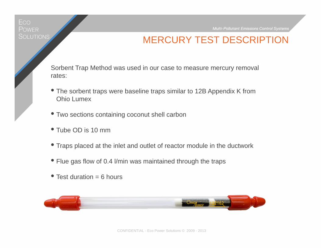
Sorbent Trap Method was used in our case to measure mercury removal rates:
• The sorbent traps were baseline traps similar to 12B Appendix K from Ohio Lumex
• Two sections containing coconut shell carbon
• Tube OD is 10 mm
• Traps placed at the inlet and outlet of reactor module in the ductwork
• Flue gas flow of 0.4 l/min was maintained through the traps
• Test duration = 6 hours
CONFIDENTIAL - Eco Power Solutions © 2009 - 2013

MERCURY TEST
Test Results (June 5, 2012):
• Traps sent to independent lab to measure deposition rates
• Mercury deposition for both the sections was measured for each trap
• Inlet duct: Section 1 = 95.38 ng; Section 2 = 0.08
• Outlet Duct: Section 1 = 9.87; Section 2 = 0.77
• Removal Rate = 89%
CONFIDENTIAL - Eco Power Solutions © 2009 - 2013
MERCURY TEST
Plan for Improvement:
• Filtration installed upstream of the reactor module
• Mist eliminators installed to reduce water carryover to the outlet duct
• Opacity levels are now in the 4 to 6% range instead of in the double digits
• Expect significant improvement in results
CONFIDENTIAL - Eco Power Solutions © 2009 - 2013

Condensation primarily consists of strong acids (low pH) and relatively weaker acids
Quantity of wastewater varies depending on temperature of flue gas entering the units.
The wastewater streams can be combined or separated for acid resale.
Byproduct is salt and water.
WASTE WATER PROCESS SCHEMATIC
CONFIDENTIAL - Eco Power Solutions © 2009 - 2013

Modular design philosophy provides for short cycle times and scale up capabilities.
25 MW Single Module (60,000 SCFM/ 28.3 N m3/sec)
75 MW Multiple Modules(180,000 SCFM/ 85.0 N m3/sec )
• Scale-up achieved through modular design.• Short cycle time (fabrication through installation)• Operational flexibility- maximum integration potential for retrofit applications• Shop assembled module units of 25 MW (projects up to 150 MW)• Field erected module units for projects > 150 MW.
DESIGNED FOR SCALE-UP & FLEXIBILITY
CONFIDENTIAL - Eco Power Solutions © 2009 - 2013

• An all–in–one, multi–pollutant AQCS that captures both regulated and unregulated air pollutants
• Over 1,000 hours of operating experience backed by credible third party validation
• Applicable to a broad range of fuel types from fossil fuels to biomass to waste fuel stock
• Flexible design allows the system to be tailored to address specific pollutants
• Cold-end location means less intrusion during the retrofit
• No modification of upstream equipment is required
• Modular and repeatable design speeds implementation and reduces costs
• Favorable capital and operating costs when compared to traditional technologies
SUMMARY
CONFIDENTIAL - Eco Power Solutions © 2009 - 2013

www.ecopowersolutions.comtwitter.com/makingcoalclean
linkedin.com/company/eco-power-solutions