Embed Size (px)
Citation preview
ORNL/TM-2019/1228 CRADA/ NFE-17-06683
Additive Manufacturing of Polyurethane Foam Mold Tooling
Dr. Brian K. Post Alex Roschli Phillip Chesser Breanna Rhyne Celeste Atkins Matthew Sallas Nikolas Tsiamis February 28, 2019
CRADA FINAL REPORT
NFE-17-06683
Approved for Public Release.
Distribution is Unlimited.
ii
DOCUMENT AVAILABILITY
Reports produced after January 1, 1996, are generally available free via US Department of Energy (DOE) SciTech Connect. Website http://www.osti.gov/scitech/ Reports produced before January 1, 1996, may be purchased by members of the public from the following source: National Technical Information Service 5285 Port Royal Road Springfield, VA 22161 Telephone 703-605-6000 (1-800-553-6847) TDD 703-487-4639 Fax 703-605-6900 E-mail [email protected] Website http://www.ntis.gov/help/ordermethods.aspx Reports are available to DOE employees, DOE contractors, Energy Technology Data Exchange representatives, and International Nuclear Information System representatives from the following source: Office of Scientific and Technical Information PO Box 62 Oak Ridge, TN 37831 Telephone 865-576-8401 Fax 865-576-5728 E-mail [email protected] Website http://www.osti.gov/contact.html
This report was prepared as an account of work sponsored by an agency of the United States Government. Neither the United States Government nor any agency thereof, nor any of their employees, makes any warranty, express or implied, or assumes any legal liability or responsibility for the accuracy, completeness, or usefulness of any information, apparatus, product, or process disclosed, or represents that its use would not infringe privately owned rights. Reference herein to any specific commercial product, process, or service by trade name, trademark, manufacturer, or otherwise, does not necessarily constitute or imply its endorsement, recommendation, or favoring by the United States Government or any agency thereof. The views and opinions of authors expressed herein do not necessarily state or reflect those of the United States Government or any agency thereof.

iii
ORNL/TM-2019/1228
CRADA/ NFE-17-06683
Energy & Transportation Science Division
Advanced Manufacturing Office
Additive Manufacturing of Polyurethane Foam Mold Tooling
Authors
Dr. Brian K. Post
Alex Roschli
Phillip Chesser
Breanna Rhyne
Celeste Atkins
Matthew Sallas
Nikolas Tsiamis
Date Published:
February 28, 2019
Prepared by
OAK RIDGE NATIONAL LABORATORY
Oak Ridge, Tennessee 37831-6283
managed by
UT-BATTELLE, LLC
for the
US DEPARTMENT OF ENERGY
under contract DE-AC05-00OR22725
Approved For Public Release

iv

iii
CONTENTS
Page
Contents ................................................................................................................................... iii List of Figures ........................................................................................................................... v Acknowledgements .................................................................................................................. vi Abstract ..................................................................................................................................... 1
1. Additive Manufacturing of Polyurethane Foam Mold Tooling ........................................... 1 1.1 Background ................................................................................................................ 1 1.2 Technical Results ....................................................................................................... 2
1.2.1 Task 1 – Long-Term Durability ............................................................................... 3 1.2.2 Task 2 – Proof of Concept for Watertight Operation .............................................. 3
1.2.3 Task 3 – Define the material trade-offs for speed, resolution, and material
performance ...................................................................................................................... 8
1.2.4 Task 4 – New foam tool design to leverage new technology .................................. 8
1.3 Impacts ....................................................................................................................... 9 1.3.1 Subject Inventions .................................................................................................. 10
1.4 Conclusions .............................................................................................................. 10
2. Whirlpool Background....................................................................................................... 12

iv
v
LIST OF FIGURES
Figure 1. Production Freezer Door Foaming Mold .................................................................. 1
Figure 2. BAAM Produced Freezer Door Foaming Mold ........................................................ 2 Figure 3. Manufactured Freezer Door from AM Tool .............................................................. 2 Figure 4. Whirlpool Ice-maker Door Tool ................................................................................ 3 Figure 5. Amana Door Foam Tool with Flow Channels .......................................................... 4 Figure 6. Leak Testing Apparatus ............................................................................................. 4
Figure 7. Leakage Failures ........................................................................................................ 4 Figure 8. Approach #2: Embedded Copper Tubing .................................................................. 5 Figure 9. Manufacturing Process .............................................................................................. 5 Figure 10. Thermal Imaging of the Copper Inlayed Door Tool ............................................... 6
Figure 11. Mold for Thermoset Resin Tool .............................................................................. 6 Figure 12. Heat Exchangers Installed in Mold ......................................................................... 7
Figure 13. Thermal Meaurement of the Cast Epoxy Tool ........................................................ 7 Figure 14. Mid-scale Printed Tool for Amana Refrigerator Door ............................................ 8 Figure 15. Mid-scale Printed High Thermal Conductivity Tool for Amana Refrigerator Door9

vi
ACKNOWLEDGEMENTS
This CRADA NFE-17-06683 was conducted as a Technical Collaboration project within the Oak
Ridge National Laboratory (ORNL) Manufacturing Demonstration Facility (MDF) sponsored by the
US Department of Energy Advanced Manufacturing Office (CPS Agreement Number 24761).
Opportunities for MDF technical collaborations are listed in the announcement “Manufacturing
Demonstration Facility Technology Collaborations for US Manufacturers in Advanced
Manufacturing and Materials Technologies” posted at
http://web.ornl.gov/sci/manufacturing/docs/FBO-ORNL-MDF-2013-2.pdf. The goal of technical
collaborations is to engage industry partners to participate in short-term, collaborative projects within
the Manufacturing Demonstration Facility (MDF) to assess applicability and of new energy efficient
manufacturing technologies. Research sponsored by the U.S. Department of Energy, Office of Energy
Efficiency and Renewable Energy, Advanced Manufacturing Office, under contract DE-AC05-
00OR22725 with UT-Battelle, LLC.

vii

1
ABSTRACT
In this DOE AMO Technical Collaboration (MDF-TC-2017-078), ORNL partnered with
Whirlpool Corporation. to develop low-cost prototype tooling for the manufacturing of refrigerators.
Techniques for producing watertight and high thermal-conductivity tools were developed and evaluated.
In addition, additive manufacturing systems at multiple volume and resolution scales were evaluated for
performance, resolution, and cost for the intended application.
1. ADDITIVE MANUFACTURING OF POLYURETHANE FOAM MOLD TOOLING
This phase two ORNL Manufacturing Demonstration Facility (MDF) technical collaboration project
(MDF-TC-2017-078) began on April 12, 2017 and was completed on February 28, 2019. The
collaboration partner, Whirlpool Corporation, is a large business. In this project, several new approaches
were developed and tested for producing functional tools for refrigerator manufacturing. Paths to
commercial systems capable of addressing the needs of the appliance industry were investigated and
ultimately, low-cost solutions for both systems and materials were determined.
1.1 BACKGROUND
Whirlpool is the industry leader in the manufacturing and marketing of home appliances. The
primary objective of the technical collaboration between ORNL and Whirlpool was to leverage the new
ORNL additive manufacturing process and materials into a long term, quick change tooling concept to
drastically reduce product lead and development timelines as well as costs.
Phase 1 of the collaboration was conducted under CRADA NFE-15-05744 from August 1, 2015
through July 29, 2016. Phase 1 successfully demonstrated the ability to produce low cost tooling for
limited production trials for Whirlpool’s refrigerator manufacturing facility’s cabinet foaming line, using
the Big Area Additive Manufacturing (BAAM) and Cosine Medium Area Additive Manufacturing
(MAAM) processes.
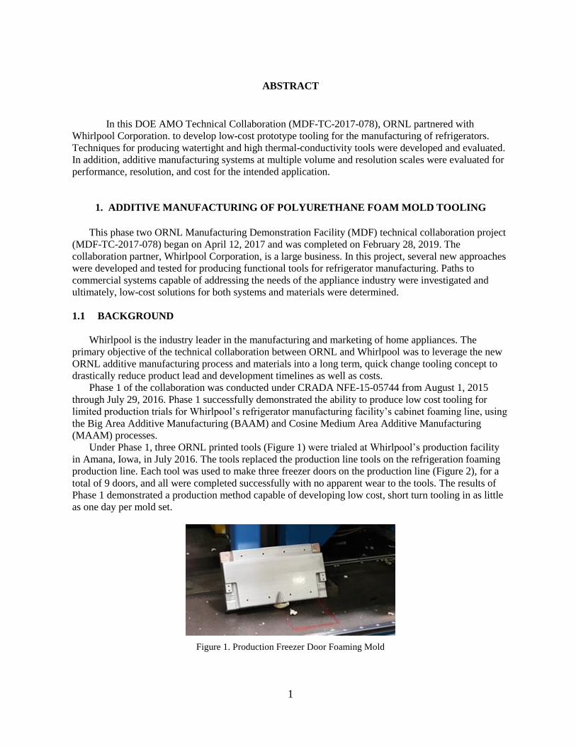
Under Phase 1, three ORNL printed tools (Figure 1) were trialed at Whirlpool’s production facility
in Amana, Iowa, in July 2016. The tools replaced the production line tools on the refrigeration foaming
production line. Each tool was used to make three freezer doors on the production line (Figure 2), for a
total of 9 doors, and all were completed successfully with no apparent wear to the tools. The results of
Phase 1 demonstrated a production method capable of developing low cost, short turn tooling in as little
as one day per mold set.
Figure 1. Production Freezer Door Foaming Mold

2
Figure 2. BAAM Produced Freezer Door Foaming Mold
Figure 3. Manufactured Freezer Door from AM Tool
The goal of Phase 2 of the project was to leverage new designs and tooling innovations in the
application of the technology to a new model line. The target was to parallel construction of a set of
foam molds based on current best practice aluminum designs. These models include the ability to heat
and cool the mold tools with forced convection with 50psi water from a thermolator.
Foam mold supports are critical for reliable, accurate production of refrigerators. However, current
foam mold supports are complicated, time-consuming, expensive, and maladaptive. In Phase 1 of this
project, Whirlpool and ORNL were successful in creating common fixture cores and providing
lightweight, easily adaptable fixture sections.
In Phase 2, ORNL aimed to test and improve the Phase 1 foam molds in several ways. First, the
long-term durability of the molds was tested. Then, the watertight concept to allow heating and cooling
of the molds was tested. ORNL worked to define the foam molds’ material trade-off curves for speed,
resolution, and material performance. Additionally, ORNL built parallel foaming molds for new and
existing products.
1.2 TECHNICAL RESULTS
The target of Phase2 focused on the needs outlined by Whirlpool, based on the results of Phase I,
namely: durability testing, high thermal conductivity and the ability to heat and cool the molds to ensure
product consistency over long production runs.

3
Phase 2 of this technical collaboration consisted of seven tasks. Task 1 was to test the long-term
durability of the foam molds. Task 2 was a proof-of-concept for watertight operation. Task 3 was to
define the material trade-offs for speed, resolution, and material performance. Task 4 was to investigate
building foam molds for new and existing products. Task 5 was to explore new foam tool design to
leverage new technology and materials. Task 6 was to improve partnership with machine manufacturers
and foam tool designers.
1.2.1 Task 1 – Long-Term Durability
In 2017, the tools made at ORNL were used in a Whirlpool production line at their production plant
in Amana, Iowa, to make 10 refrigerator doors each, and the CMM data was collected confirm
dimensional accuracy. Unfortunately, due to production schedule changes, the model of refrigerator that
the tools were designed for was taken out of production, and the durability testing is awaiting the restart
of that product line in the production facility. In addition, to address the issues in production at the
Amana facility, a second tool (Figure 4) was identified as an ice maker door tool for an Ohio plant.
Figure 4. Whirlpool Ice-maker Door Tool
ORNL produced one of the tools from a reverse-engineered model of the existing tool, printed a
replica, machined and delivered it to the factory. The engineers at the plant struggled installing and
testing the tool without crushing the corners of the liners. Therefore, at the end of project, durability
testing is still awaiting the restart of the Amana production.
1.2.2 Task 2 – Proof of Concept for Watertight Operation
To meet the objective of creating full cabinet molds suitable for production volume tooling, a
methodology for routing 50psi water through the tools needed to be determined. In production, water
conditioned by a thermolator is used to either heat or cool the tools in order to achieve the desired
setpoint (around 100 degrees Fahrenheit).
Most fused deposition polymer printers are incapable of producing watertight components because
of the voids left between beads of material. Because of the bead geometry and material extrusion
pressures of the BAAM process, it has been determined that water-tight components can be successfully
printed for constrained geometries. The first successful watertight tool was designed to have a serpentine
path through the polymer tool for the fluid, as shown in Figure 5.

4
Figure 5. Amana Door Foam Tool with Flow Channels
This part was fabricated and tested using the experimental apparatus shown in Figure 6. Using a
regulated commercial water supply of 50psi, water was forced into the part, compressing the trapped air
which resulted in a corresponding pressure reading on the flow exit. In the worst case scenario of
blocked flow, the tool could see the full 50psi in production, so the tool must be capable of withstanding
>50psi in order to be considered successful.
Figure 6. Leak Testing Apparatus
At low pressures, the first tools exhibited leaks at the top surfaces of the tool due to macro-scale
voids in the solid fill layers. This type of leakage is shown Figure 7a.
Figure 7. Leakage Failures
a b

5
In subsequent trials, this leakage phenomenon was eliminated through toolpath modifications to
ensure these macro voids were staggered on subsequent layers to avoid leakage paths, and also through
parameter adjustments to ensure complete profile fill.
The second form of leakage observed were interlaminar failures at higher pressures (20-30psi).
These leaks, as shown in Figure 7b, were initiated between layers caused by pressure forces
overcomming the inter-laminar bond strength of the printed component. These failures were typically
accompanied by an audible cracking noise and, once initiated, the leaks were permanent, even at lower
pressures. As a result, this methodology was deemed unsatisfactory for the application unless new
materials with better interlaminar strength can be determined.
A second approach was developed wherein copper tubing was inserted into a thin shell door foam
tool, as shown in Figure 8. The back side of the shell is insulated with expanding foam to prevent heat
loss to non-critical surfaces. Water flows through the tube in the mold and conducts to the surface of the
tool.
Figure 8. Approach #2: Embedded Copper Tubing
Pictures of the fabrication of one of these tools are shown in Figure 9. Note that the copper tubing is
fabricated using a mandrel and bonded to the machined groove in the machined part.
Figure 9. Manufacturing Process
This process results in a watertight part capable of supporting the 50psi thermolator pressure.

6
Whirlpool tested these tools for their thermal conductivity by attaching a thermolator and measuring the
surface temperature profile with a thermal camera.
Figure 10. Thermal Imaging of the Copper Inlayed Door Tool
While the tool was functional and better than the original tools developed in Phase 1 of the project,
the limited thermal conductivity of thermoplastic materials significantly hindered the thermal
performance of the tools, as illustrated in Figure 10. With a setpoint of 125 degrees Fahrenheit, the tool
surface only reached 100 degrees at its warmest point, and towards the edges this significantly dropped
to 80 degrees. Thermoplastic resin systems generally have thermal conductivity coefficients of 0.1-
0.5W/mK. Therefore, most printable polymers would perform similarly.
In order to improve the thermal conductivity of the tools, the decision was made to cast a high
thermal conductivity (~10W/mK ) epoxy tool from a BAAM printed mold. Figure 11 shows the printed
and machined mold. Ceramacast 673-N, a highly filled (with Silicon Carbide) resin from Aremco, was
chosen based on the thermal conductivity requirements.
Figure 11. Mold for Thermoset Resin Tool
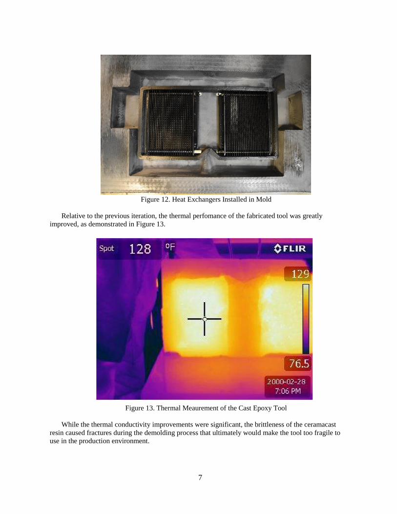
Heat exchangers, which are commercially available transmission coolers, were installed in a printed
frame within the mold, as shown in Figure 12. Epoxy was poured into the mold to fully encapsulate the
heat exchangers.
7
Figure 12. Heat Exchangers Installed in Mold
Relative to the previous iteration, the thermal perfomance of the fabricated tool was greatly
improved, as demonstrated in Figure 13.
Figure 13. Thermal Meaurement of the Cast Epoxy Tool
While the thermal conductivity improvements were significant, the brittleness of the ceramacast
resin caused fractures during the demolding process that ultimately would make the tool too fragile to
use in the production environment.

8
1.2.3 Task 3 – Define the material trade-offs for speed, resolution, and material performance
In order to meet the demands of the application, the primary targets were resolution and material
performance. It was determined through Task 2 that the minimum thermal conductivity necessary is
>5W/mK. Most thermoplastics are much lower, around 0.1W/mK. The trade-off for using thermoplastic
tools ultimately falls on the end use application. There exists a subset of refrigeration foam tools that are
not heated. For those applications, the polymer tools perform adequately and the lead times available
through AM are much better than traditional tooling routes. Therefore, for prototype tooling, AM
polymer tools work and provide a significant value proposition.
The second tradeoff of speed vs resolution reduces to amount of postprocessing necessary to achieve
a functional tool. It was determined that parts produced on high resolution 3D printers could be used
without any post processing. However, the maximum build size, material cost, and build rates limit the
utility of these systems to create tools for this application. The BAAM or other similarly sized printers
are much too large and print at too low a resolution to ultimately be applicable to the appliance industry.
Through this project it was identified that a midscale system with sub 1mm nozzle sizes and deposition
rates >5lb per hour would be ideal and require no postprocessing.
1.2.4 Task 4 – New foam tool design to leverage new technology
During the execution of this research program, many new “midscale” polymer AM systems were
released. Two of these were used to produce tools for refrigerator foam injection.
Figure 14. Mid-scale Printed Tool for Amana Refrigerator Door
The tool shown in Figure 14 was printed on a Cosine AM1 using 3mm filament with a print time around
20hrs. This tool was tested successfully at the Amana production facility. The resolution was high
enough that, without any post processing, the stair-stepping in the tool surface was not transferred to the
liner during the foaming process. However, the shrinkage noticed in the tool after print was too high to
produce an in-spec refrigerator door.
9
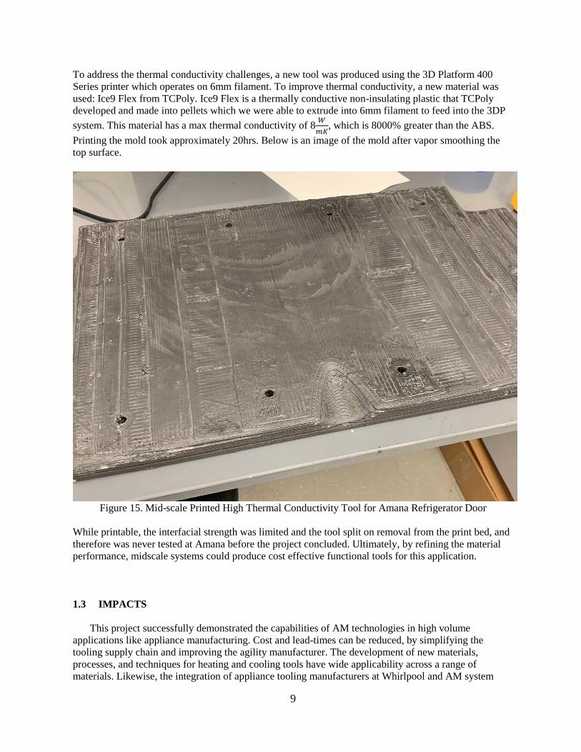
To address the thermal conductivity challenges, a new tool was produced using the 3D Platform 400
Series printer which operates on 6mm filament. To improve thermal conductivity, a new material was
used: Ice9 Flex from TCPoly. Ice9 Flex is a thermally conductive non-insulating plastic that TCPoly
developed and made into pellets which we were able to extrude into 6mm filament to feed into the 3DP
system. This material has a max thermal conductivity of 8𝑊
𝑚𝐾, which is 8000% greater than the ABS.
Printing the mold took approximately 20hrs. Below is an image of the mold after vapor smoothing the
top surface.
Figure 15. Mid-scale Printed High Thermal Conductivity Tool for Amana Refrigerator Door
While printable, the interfacial strength was limited and the tool split on removal from the print bed, and
therefore was never tested at Amana before the project concluded. Ultimately, by refining the material
performance, midscale systems could produce cost effective functional tools for this application.
1.3 IMPACTS
This project successfully demonstrated the capabilities of AM technologies in high volume
applications like appliance manufacturing. Cost and lead-times can be reduced, by simplifying the
tooling supply chain and improving the agility manufacturer. The development of new materials,
processes, and techniques for heating and cooling tools have wide applicability across a range of
materials. Likewise, the integration of appliance tooling manufacturers at Whirlpool and AM system

10
researchers at ORNL has resulted in additional technology demonstrations and projects that could
revolutionize appliance manufacturing by reducing costs and improving the durability of stamping tools.
1.3.1 Subject Inventions
There are no subject inventions associated with this CRADA .
1.4 CONCLUSIONS
In this Phase 2 project, several new approaches were developed and tested for producing functional
tools for refrigerator manufacturing. While many of the approaches met one or more of the criteria for
success (i.e. durability, thermal conductivity, resolution, production rate, or cost), none of them have as
of yet demonstrated the complete solution to this complex challenge.
With the rapid growth in AM capabilities over the course of this project, several new systems and
materials were developed and tested, and future systems offer promise for low-cost AM at scales
relevant to appliance manufacturers. Paths to commercial systems capable of addressing the needs of the
appliance industry were investigated and ultimately, low-cost solutions for both systems and materials
were determined.

11

12
2. WHIRLPOOL BACKGROUND
Whirlpool Corporation (NYSE: WHR) is the world’s leading major home appliance company, with
approximately $21 billion in annual sales, 92,000 employees, and 65 manufacturing and technology
research centers in 2018. The company markets Whirlpool, KitchenAid, Maytag, Consul, Brastemp,
Amana, Bauknecht, JennAir, Indesit and other major brand names in nearly every country throughout the
world. In 2018, Whirlpool and its associated brands sold 68 million products globally. 54% of those
products were sold in North America. 22% of those products were sold in Europe, Middle East, and
Africa. 17% of those products were sold in Latin America, and 7% of those products were sold in Asia.