Embed Size (px)
Citation preview
Faculdade de Engenharia da Universidade do Porto
Additive manufacturing of custom-fit orthoses for the upper limb
Ana Sofia Teixeira de Jesus Faria
Dissertation carried out under the Integrated Master in Bioengineering
Biomedical Engineering
Supervisor: Professor José Domingos Santos, PhD Co-supervisor: Margarida Machado, PhD
Porto, March 2017

ii
© Ana Faria, 2017
iii
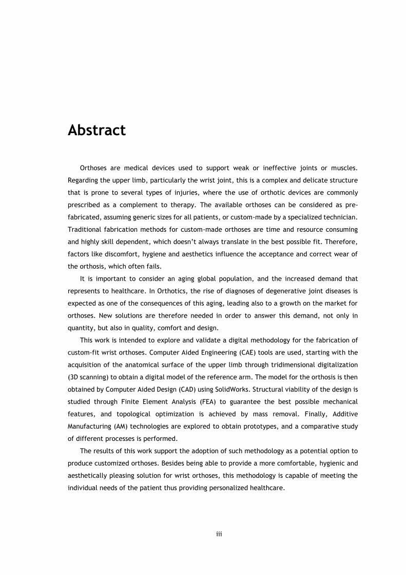
Abstract
Orthoses are medical devices used to support weak or ineffective joints or muscles.
Regarding the upper limb, particularly the wrist joint, this is a complex and delicate structure
that is prone to several types of injuries, where the use of orthotic devices are commonly
prescribed as a complement to therapy. The available orthoses can be considered as pre-
fabricated, assuming generic sizes for all patients, or custom-made by a specialized technician.
Traditional fabrication methods for custom-made orthoses are time and resource consuming
and highly skill dependent, which doesn’t always translate in the best possible fit. Therefore,
factors like discomfort, hygiene and aesthetics influence the acceptance and correct wear of
the orthosis, which often fails.
It is important to consider an aging global population, and the increased demand that
represents to healthcare. In Orthotics, the rise of diagnoses of degenerative joint diseases is
expected as one of the consequences of this aging, leading also to a growth on the market for
orthoses. New solutions are therefore needed in order to answer this demand, not only in
quantity, but also in quality, comfort and design.
This work is intended to explore and validate a digital methodology for the fabrication of
custom-fit wrist orthoses. Computer Aided Engineering (CAE) tools are used, starting with the
acquisition of the anatomical surface of the upper limb through tridimensional digitalization
(3D scanning) to obtain a digital model of the reference arm. The model for the orthosis is then
obtained by Computer Aided Design (CAD) using SolidWorks. Structural viability of the design is
studied through Finite Element Analysis (FEA) to guarantee the best possible mechanical
features, and topological optimization is achieved by mass removal. Finally, Additive
Manufacturing (AM) technologies are explored to obtain prototypes, and a comparative study
of different processes is performed.
The results of this work support the adoption of such methodology as a potential option to
produce customized orthoses. Besides being able to provide a more comfortable, hygienic and
aesthetically pleasing solution for wrist orthoses, this methodology is capable of meeting the
individual needs of the patient thus providing personalized healthcare.

iv
v
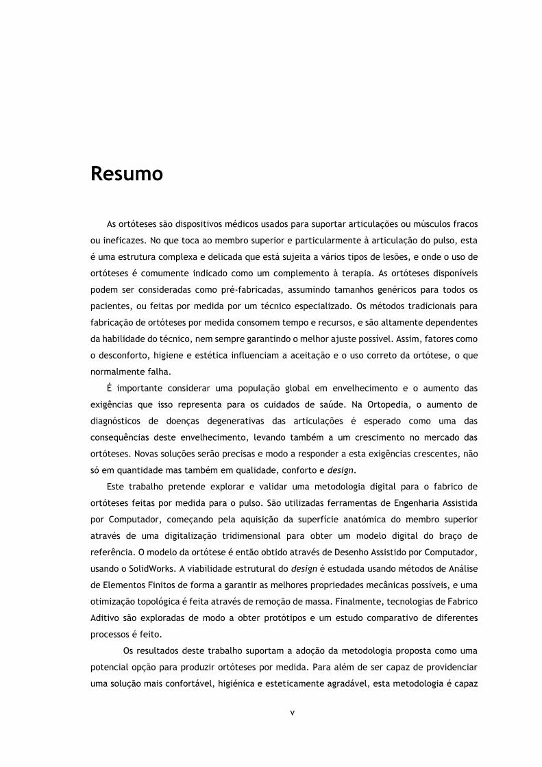
Resumo
As ortóteses são dispositivos médicos usados para suportar articulações ou músculos fracos
ou ineficazes. No que toca ao membro superior e particularmente à articulação do pulso, esta
é uma estrutura complexa e delicada que está sujeita a vários tipos de lesões, e onde o uso de
ortóteses é comumente indicado como um complemento à terapia. As ortóteses disponíveis
podem ser consideradas como pré-fabricadas, assumindo tamanhos genéricos para todos os
pacientes, ou feitas por medida por um técnico especializado. Os métodos tradicionais para
fabricação de ortóteses por medida consomem tempo e recursos, e são altamente dependentes
da habilidade do técnico, nem sempre garantindo o melhor ajuste possível. Assim, fatores como
o desconforto, higiene e estética influenciam a aceitação e o uso correto da ortótese, o que
normalmente falha.
É importante considerar uma população global em envelhecimento e o aumento das
exigências que isso representa para os cuidados de saúde. Na Ortopedia, o aumento de
diagnósticos de doenças degenerativas das articulações é esperado como uma das
consequências deste envelhecimento, levando também a um crescimento no mercado das
ortóteses. Novas soluções serão precisas e modo a responder a esta exigências crescentes, não
só em quantidade mas também em qualidade, conforto e design.
Este trabalho pretende explorar e validar uma metodologia digital para o fabrico de
ortóteses feitas por medida para o pulso. São utilizadas ferramentas de Engenharia Assistida
por Computador, começando pela aquisição da superfície anatómica do membro superior
através de uma digitalização tridimensional para obter um modelo digital do braço de
referência. O modelo da ortótese é então obtido através de Desenho Assistido por Computador,
usando o SolidWorks. A viabilidade estrutural do design é estudada usando métodos de Análise
de Elementos Finitos de forma a garantir as melhores propriedades mecânicas possíveis, e uma
otimização topológica é feita através de remoção de massa. Finalmente, tecnologias de Fabrico
Aditivo são exploradas de modo a obter protótipos e um estudo comparativo de diferentes
processos é feito.
Os resultados deste trabalho suportam a adoção da metodologia proposta como uma
potencial opção para produzir ortóteses por medida. Para além de ser capaz de providenciar
uma solução mais confortável, higiénica e esteticamente agradável, esta metodologia é capaz

vi
de ir de encontro às necessidades individuais de cada paciente, fornecendo um cuidado de
saúde personalizado.

vii
Acknowledgements
Gostaria de começar por agradecer ao prof. José Domingos Santos por me ter aberto as
portas a este tema e por me ter ajudado a orientar este trabalho, partilhando sempre comigo
o seu entusiasmo. Este trabalho não seria possível sem a colaboração do INEGI, ao qual agradeço
desde já a oportunidade e também ao projeto de investigação que o suportou, a operação
NORTE-01-0145-FEDER-000022 – SciTech – Science and Technology for Competitive and
Sustainable Industries, cofinanciada pelo Programa Operacional Regional do Norte
(NORTE2020) através do Fundo Europeu de Desenvolvimento Regional (FEDER).
À Doutora Margarida Machado, por todo o apoio, interesse e horas passadas comigo a
procurar fazer mais e melhor. A sua dedicação, sempre incansável, foi sem dúvida uma
motivação muito importante que contribuiu para o sucesso deste trabalho.
Agradeço ainda a todos os colaboradores do INEGI que me ajudaram, em especial à Mafalda
Couto, ao Tiago Guimarães e ao Isaac Ferreira e também ao prof. Jorge Belinha, à fisioterapeuta
Fátima Dória, à Engª. Ana Brandão e à Cristina.
Estes últimos anos não teriam sido os mesmos sem o meu grupo de amigos, ao qual agradeço
por todas as histórias, gargalhadas e aventuras que sem dúvida tornaram o meu percurso
inesquecível. À Madalena, o meu braço direito desde o início, um obrigado muito especial, e à
sua família, por me fazerem sempre sentir em casa.
Quero ainda agradecer à Tuna Feminina de Engenharia, que providenciou a banda sonora
dos meus anos de faculdade, pela música, vivências e amizades, e por me ensinar um pouco
daquilo que não se aprende nas salas de aula.
Por fim, agradeço à minha família, particularmente ao meu irmão e aos meus pais, que
apesar de longe sempre me deram todo o apoio possível e imaginário e que sempre acreditaram
em mim, às vezes mais do que eu.

viii

ix
“Adversity introduces a man to himself.”
Albert Einstein

x
xi
Contents
Introduction ................................................................................................ 1 1.1 - Context and motivation ................................................................. 1 1.2 - Literature review ........................................................................... 2 1.3 - Objectives ................................................................................... 6 1.4 - Contributions ............................................................................... 6 1.5 - Document structure ...................................................................... 7
Clinical Background ....................................................................................... 9 2.1 - Anatomy and biomechanics of the hand and wrist .............................. 9 2.2 - Orthotics in rehabilitation ............................................................ 16
Digital Tools and Methods ............................................................................. 27 3.1 - Anatomical data acquisition ............................................................ 27 3.2 - Computer Aided Design ................................................................. 30 3.3 - Computer Aided Engineering........................................................... 31 3.4 - Additive Manufacturing technology .................................................. 32 3.5 - Engineering-based approach for fabrication of orthoses ........................ 35
Conceptual Design ...................................................................................... 37 4.1 - Concept generation ...................................................................... 37 4.2 - Designing for AM .......................................................................... 42 4.3 - Orthosis modelling........................................................................ 44
Abstract ........................................................................................... iii
Resumo ............................................................................................ v
Acknowledgements ............................................................................ vii
Contents .......................................................................................... xi
List of Figures ................................................................................. xiii
List of Tables ..................................................................................xvii
Abbreviations .................................................................................. xix
Chapter 1 ......................................................................................... 1
Chapter 2 ......................................................................................... 9
Chapter 3 ........................................................................................ 27
Chapter 4 ........................................................................................ 37

xii
Mechanical Design ...................................................................................... 55 5.1 - Numerical model validation ............................................................ 55 5.2 - Structural analysis ........................................................................ 58 5.3 - Design optimization ...................................................................... 61
Additive Manufacturing ................................................................................ 65 6.1 - First prototype ............................................................................ 65 6.2 - Second prototype ......................................................................... 67 6.3 - Third prototype ........................................................................... 69 6.4 - Comparative study ....................................................................... 71
Conclusions and Future Work ....................................................................... 73
Chapter 5 ........................................................................................ 55
Chapter 6 ........................................................................................ 65
Chapter 7 ........................................................................................ 73
References ...................................................................................... 75
Appendix A ...................................................................................... 79
Appendix B ...................................................................................... 87
Appendix C ...................................................................................... 89
xiii
List of Figures
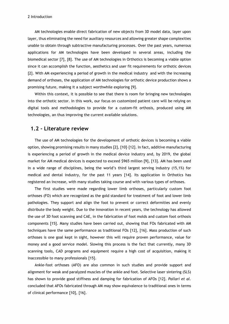
Figure 1.1 – Available 3D printed casts and orthoses. A: Osteoid arm cast [17]. B: Cortex arm cast [18]. C: Hashcast [19]. D: Xkelet arm cast [20]. E: moldable wrist orthosis by Zdavprint [27]. F: flat, molded and with added Velcro straps moldable wrist orthosis by Singh [22]. G: Novacast [24]. H: 3D printed thumb orthosis by ActivArmor [25]. I: wrist orthosis by Younext [26]. ...................................................................... 4
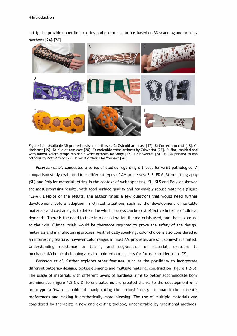
Figure 1.2 – Wrist orthoses developed by Paterson et al. A: wrist orthosis, SL build with showing support structures [2]. B: different pattern approaches to a wrist orthosis [3]. C: multimaterial construction to allow cushioning of bony prominences [3]. ............... 5
Figure 2.1- A: bones of the right hand, dorsal view [32]. B: skeletal arches of the hand [1]. C: carpal tunnel: space between concave carpus and transverse retinacular ligament, enclosing the median nerve and flexor tendons of the fingers [31]. ........................ 10
Figure 2.2 - Joints of the carpus [31]. ................................................................... 11
Figure 2.3 – Palmar view of the ligaments of the left wrist and hand [31]. ....................... 12
Figure 2.4 - Movements of the hand and forearm. A: forearm pronation and supination. B: radial and ulnar deviation of the hand. C: wrist flexion and extension. D: flexion, extension and hyper-extension of finger related to MCP joint. E: fingers abduction and adduction (adapted from [37]). .................................................................... 13
Figure 2.5 – Carpal tunnel syndrome: the median nerve is compressed at the wrist, resulting in numbness or pain in the thumb, index, middle and ring fingers [42]. ................... 15
Figure 2.6 – Comparison between normal and arthritic wrist and hand. Diseased joints are inflamed and damaged [44]. ........................................................................ 16
Figure 2.7 – ASHT’s Splint Classification System (adapted from [49]). ............................. 18
Figure 2.8 - Proximal interphalangeal (PIP) joint orthoses with different purposes. A: PIP immobilization orthosis. B: PIP flexion mobilization orthosis. C: PIP extension orthosis [49]. ..................................................................................................... 19
Figure 2.9 - Choices of orthotic designs. A: static wrist immobilization orthosis [54]. B: serial static IP extension mobilization orthosis [49]. ........................................... 20
Figure 2.10 - Choices of orthotic designs. A: dynamic MCP extension orthosis [58]. B: static progressive PIP extension orthosis [59]. .......................................................... 21
Figure 2.11 – Traditional processes for fabrication of orthoses. A: vacuum press for foot orthoses [60]. B: molding of a polypropylene AFO through a suction cone [61]. C: thermoplastic (Multicast thermoplastic, composed of polycaprolactone and
xiv
polyurethane) sheet heated in water bath. D: molding of the material to the patient’s arm [62]. ............................................................................................... 22
Figure 2.12 – Workflow of the traditional method for building orthoses (adapted from [2]). . 23
Figure 2.13 – A: workstation for orthosis fabrication with two visible AFOs. B: 3mm thick perforated thermoplastic material used for orthoses. ......................................... 24
Figure 3.1 – Initial setup for 3D scanning of the reference arm. A: applied powder to the skin and markers. B: setup for initial test. ....................................................... 28
Figure 3.2 - 3D Scan of hand and forearm. A C: position of equipment for superior surface data acquisition. D: Real time software reconstruction. ...................................... 29
Figure 3.3 – Obtaining the plaster cast model of the hand. A: Pouring the alginate mix into the plastic container, with the hand in position. B: Pouring the plaster mix into the mold. C: removing the solidified alginate and revealing the solidified plaster. D: Plaster model of the hand, palmar view. E: Plaster model of the hand, dorsal view. ... 30
Figure 3.4 – Model of scanned arm. A: palmar and dorsal views of the imported mesh from 3-matic to MeshMixer; gaps and overlaps are still visible through the faulty edges (blue). B: palmar view of the final model and corresponding dimensions (147.06x54.31x303.65 mm). C: dorsal view of the final reconstructed model ............ 31
Figure 3.5 - Liquid/solid/powder based classification of AM processes [80]. .................... 33
Figure 3.6 - Illustration of Stereolithography setting [82]. .......................................... 34
Figure 3.7 - Illustration of Fused Deposition Modelling setting [83]. ............................... 34
Figure 3.8 – Workflow for the followed approach for fabrication of custom-fit orthoses. ..... 35
Figure 4.1 – Joints and flexion creases of the hand [88]. ............................................ 38
Figure 4.2 – Dorsal and volar views of the bony prominences of the hand [88]. ................. 39
Figure 4.3 – First class lever example on a wrist neutral immobilization splint. A represents the axis at the wrist, R the hand weight or resistance and F the counterforce provided by the forearm [1]. ................................................................................... 39
Figure 4.4 – Printing results of the “YHT” rule. The “H” and “T” shapes present some drooped filaments due to the lack of support material [89]. ................................. 42
Figure 4.5 – Automatically generated supports on MeshMixer with a 45º angle threshold for different shapes. ...................................................................................... 43
Figure 4.6 – STL vs CAD format of a doughnut-shaped model. X represents the CAD model surface, and a,b and c represent the edges of the triangular representation of the STL model [93]. ............................................................................................ 45
Figure 4.7 – First approach for CAD modelling. A: intersecting planes with the STL imported model. B: resulting contours. C: resulting surface after loft procedure, with a visible gap near the thumb area. ........................................................................... 46
Figure 4.8 – Obtaining a shell model for the reference arm. A: selected surface. B: 0.5mm offset surface. C: inferior view of the 0.5mm offset surface. D: inferior view of the second offset surface, 3mm away from the first one. E: inferior view of the connected surfaces/solid model. ................................................................................ 46
xv
Figure 4.9 – CAD model obtained through the conversion of the STL file using Geomagic for SolidWorks. ............................................................................................. 47
Figure 4.10 – Obtaining the shape of a wrist orthosis. A: reference lines for splitting the shell. B: resulting body after splitting. ............................................................ 47
Figure 4.11 – Designing a two part orthosis model. A: sketched path and profile for the hole on a section view of the model. B: outline of the resulting holes along the model. C: sketch and respective dimensions used for splitting the body. D: resulting extruded surface, used to split the body in two. ............................................................ 48
Figure 4.12 – Fitting part details. A: sketch on cut surface for and elliptical groove/boss. B: resulting groove in bottom part. C: resulting boss on top part. D: Detail of the fitting of the boss into the groove; fitting of the puzzle-like protuberances is also visible. .................................................................................................. 49
Figure 4.13 – Rendered images of the orthosis model. A, B: Positioning the top and bottom parts on the arm. C, D: Assembled parts and fitting on the arm. ............................ 49
Figure 4.14 – Result of the applied Voronoi pattern on the reference arm surface, using MeshMixer. ............................................................................................. 50
Figure 4.15 – Designing the tear-shaped material removal cells. A: right, middle and left sketches, manually disposed and with consideration of the border lines. B: performing an extruded cut on the left side, using a guideline (blue) for direction. ................... 51
Figure 4.16 – Final mass reduction models. A: rendered image (using SolidWoks) of the regular distribution lozenge cell on the reference arm. B: top and bottom MeshMixer view of the non-regular distribution lozenge cell. C: top and bottom MeshMixer view of the tear cell. D: top and bottom MeshMixer view of the almond cell. ................... 51
Figure 4.17 – Second version of the non-regular distribution lozenge cell. A: new enclosure method between the fingers, following the same pin and hole approach as the laterals. B: added grooves next to the holes extremities. C: MeshMixer view of the top and bottom parts assembly. D, F: Rendered image (using SolidWorks) of the new orthosis version on the reference arm. ........................................................... 52
Figure 4.18 – Increasing the radius in some of the lozenge cells on the third model version. ........................................................................................................... 53
Figure 5.1 – Setup for wrist force measurement using a dynamometer. ........................... 56
Figure 5.2 – Free body diagram of the trial simulation. F represents the applied force of 30N. The green edge represents the fixed restriction of the proximal edge. .............. 56
Figure 5.3 –Equivalent von Mises stress distribution for the performed simulation (normalized from 0 to 4.628 MPa). A: SolidWorks results. B: ANSYS results. .............. 57
Figure 5.4 – Free body diagrams for FEA. A: flexion. B: extension. C: radial deviation. D: ulnar deviation......................................................................................... 58
Figure 5.5 – Mesh convergence study, considering 8, 6, 4 and 3 mm element size. A: flexion movement. B: extension movement. C: radial deviation. D: ulnar deviation. ............. 59
Figure 5.6 – Resulting mesh of 3mm tetrahedral elements. ......................................... 59
Figure 5.7 – Von Mises stress distribution simulation results, from the minimum to the maximum stress value. A: flexion. B: extension. C: radial deviation. D: ulnar deviation. ............................................................................................... 60
xvi
Figure 5.8 – Normalized von Mises stress distribution, ranged from 0 to 30 MPa. A: flexion. B: extension. C: radial deviation. D: ulnar deviation.......................................... 61
Figure 5.9 – Rounded corners of the regular distribution model (as seen from below). It is possible to see that most corners show higher stress concentrations. ...................... 62
Figure 5.10 - Von Mises stress distribution simulation results for the regular distribution model. A: flexion. B: extension. C: radial deviation. D: ulnar deviation. .................. 63
Figure 5.11 - Von Mises stress distribution simulation results, for the non-regular distribution model. A: flexion. B: extension. C: radial deviation. D: ulnar deviation. ... 63
Figure 6.1 – Stereolithography process. A: pre-processing made using PreForm software, with automatic orientation and generated supports. B: materialized result of the printing on Form 2. C: prominences resulting from support removal. D: green parts at the UV chamber. ...................................................................................... 66
Figure 6.2 - Orthosis prototype obtained by SL. A,B: fitting on the reference arm. C: top and bottom parts, post-cured. D: Top view of the assembled parts. D: bottom view of the assembled parts. ................................................................................. 66
Figure 6.3 – Problems found on the first prototype. A: material contraction. B: ineffectiveness of closing mechanism between near fingers. D: loose gap at the proximal extremity. D: sliding of the metallic wire through the hole. E: ineffective extremity at the medial side junction. F: material placed over the ulnar styloid process, marked with a red circle. ................................................................ 67
Figure 6.4 – Fused deposition modelling process. A: pre-processing made at support software, where supports were added. B: printer head depositing material. C: top and bottom parts after printing; supports and loose filaments are visible. ..................... 68
Figure 6.5 - Orthosis prototype obtained by FDM. A: fitting on the reference arm, palmar view. B: fitting on the reference arm, dorsal view; the missing portion is visible. C: top and bottom parts, post-cured. D: top view of the assembled parts. D: bottom view of the assembled parts, where the grooves made to accommodate the metal wire are visible. .................................................................................................. 68
Figure 6.6 – Details and corrected issues. A: medial enclosure portion; the wire is visible due to cracks on the borders of the hole. B: material removal at the ulnar styloid process. C: missing portion at the between the fingers junction. D: detail on surface quality. ................................................................................................. 69
Figure 6.7 – Pre-processing made at support software, with orientation and application of supports. ............................................................................................... 70
Figure 6.8 – Third prototype obtained by SL. A: fitting on the reference arm, palmar view. B: fitting on the reference arm, dorsal view; the mission portion is visible. C: top and bottom parts, post-cured. D: detail on the dorsal junction near the fingers. ............. 70
xvii
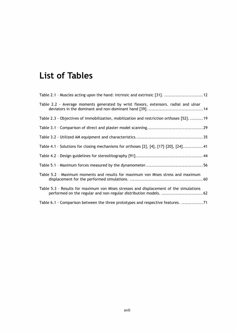
List of Tables
Table 2.1 – Muscles acting upon the hand: intrinsic and extrinsic [31]. ........................... 12
Table 2.2 - Average moments generated by wrist flexors, extensors. radial and ulnar deviators in the dominant and non-dominant hand [39]. ...................................... 14
Table 2.3 - Objectives of immobilization, mobilization and restriction orthoses [52]. ......... 19
Table 3.1 – Comparison of direct and plaster model scanning. ...................................... 29
Table 3.2 - Utilized AM equipment and characteristics. .............................................. 35
Table 4.1 – Solutions for closing mechanisms for orthoses [2], [4], [17]–[20], [24]. ............. 41
Table 4.2 – Design guidelines for stereolitography [91]. .............................................. 44
Table 5.1 – Maximum forces measured by the dynamometer. ....................................... 56
Table 5.2 – Maximum moments and results for maximum von Mises stress and maximum displacement for the performed simulations. ................................................... 60
Table 5.3 – Results for maximum von Mises stresses and displacement of the simulations performed on the regular and non-regular distribution models. ............................. 62
Table 6.1 - Comparison between the three prototypes and respective features. ............... 71

xviii
xix
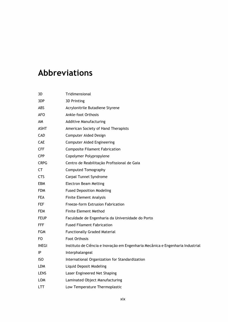
Abbreviations
3D Tridimensional
3DP 3D Printing
ABS Acrylonitrile Butadiene Styrene
AFO Ankle-foot Orthosis
AM Additive Manufacturing
ASHT American Society of Hand Therapists
CAD Computer Aided Design
CAE Computer Aided Engineering
CFF Composite Filament Fabrication
CPP Copolymer Polypropylene
CRPG Centro de Reabilitação Profissional de Gaia
CT Computed Tomography
CTS Carpal Tunnel Syndrome
EBM Electron Beam Melting
FDM Fused Deposition Modeling
FEA Finite Element Analysis
FEF Freeze-form Extrusion Fabrication
FEM Finite Element Method
FEUP Faculdade de Engenharia da Universidade do Porto
FFF Fused Filament Fabrication
FGM Functionally Graded Material
FO Foot Orthosis
INEGI Instituto de Ciência e Inovação em Engenharia Mecânica e Engenharia Industrial
IP Interphalangeal
ISO International Organization for Standardization
LDM Liquid Deposit Modeling
LENS Laser Engineered Net Shaping
LOM Laminated Object Manufacturing
LTT Low Temperature Thermoplastic
xx
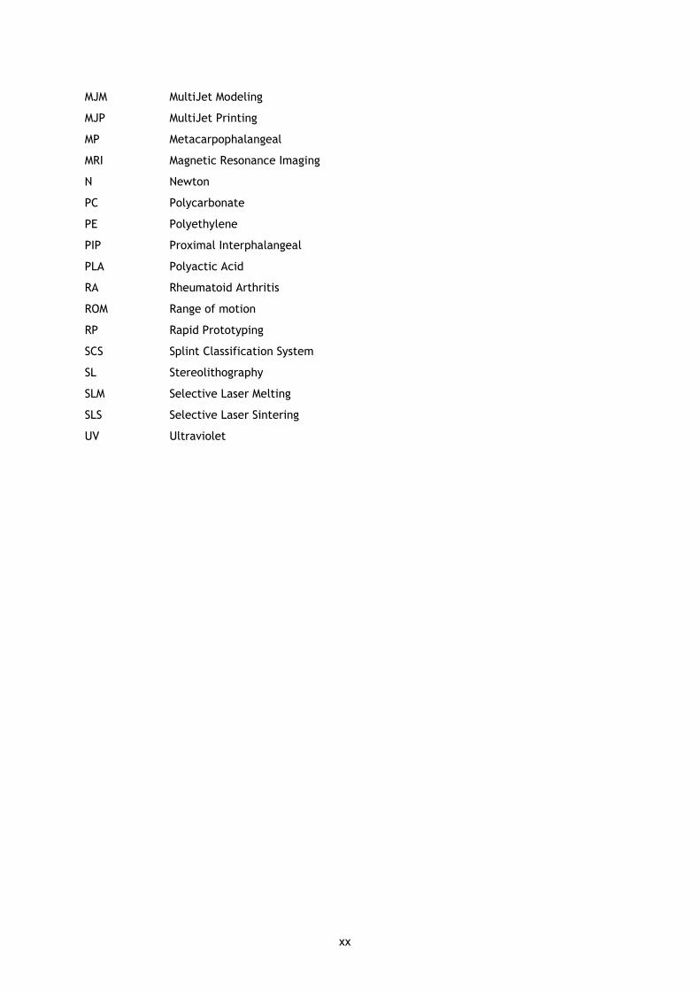
MJM MultiJet Modeling
MJP MultiJet Printing
MP Metacarpophalangeal
MRI Magnetic Resonance Imaging
N Newton
PC Polycarbonate
PE Polyethylene
PIP Proximal Interphalangeal
PLA Polyactic Acid
RA Rheumatoid Arthritis
ROM Range of motion
RP Rapid Prototyping
SCS Splint Classification System
SL Stereolithography
SLM Selective Laser Melting
SLS Selective Laser Sintering
UV Ultraviolet
Chapter 1
Introduction
1.1 - Context and motivation
Orthoses are medical devices designed to support weak or ineffective joints or muscles and
are applied in multiple situations and purposes such as to increase function, prevent or correct
deformity and restrict motion [1]. They can be acquired as a prefabricated “off-the-shelf”
product or they can be custom-made.
Prefabricated orthoses rely on a “one-size-fits-all” strategy, meaning that generic sizes are
available and therefore are not tailored to fit a specific individual unless adjusted by the user
or by an orthotic technician. On the other hand, traditional custom-made orthoses are
dependent of the materials and fabrication processes’ limitations, compromising the fit and
function. Due to the fact that the fabrication process is manual and skill dependent, the
orthosis may be poorly fitted, resulting in shear stress, directional misalignment and pressure
over bony prominences that can result in unwanted pressure sores. Another relevant
disadvantage found on both cases comes from the thickness of the material and limited
perforation that may induce excessive perspiration, stimulating bacteria growth and leading to
an odorous, unhygienic and difficult to keep clean form of treatment [2], [3].
Patient acceptance and wear of an orthotic device often fails, due to several reasons such
as not understanding its goal, the orthosis being uncomfortable or impractical, hygiene issues
or aesthetics. This might end up compromising the wear schedule and therefore the therapy
results. In fact, two-thirds of patients report non-compliance in the wear or their orthotic
device [2]–[4]. Aesthetics plays an important role in the willingness to wear the orthosis, since
orthoses typically look clinical and unattractive, regardless of its quality [5].
With the increase of an aging population and consequent growing of related diseases and
disorders, a rise in the demand and quality of orthotic devices is expected [6]. This leads to
the need for the development of new modelling and manufacturing techniques capable of
providing a more efficient response.
2 Introduction
AM technologies enable direct fabrication of new objects from 3D model data, layer upon
layer, thus eliminating the need for auxiliary resources and allowing greater shape complexities
unable to obtain through subtractive manufacturing processes. Over the past years, numerous
applications for AM technologies have been developed in several areas, including the
biomedical sector [7], [8]. The use of AM technologies in Orthotics is becoming a viable option
since it can accomplish the function, aesthetics and user fit requirements for orthotic devices
[2]. With AM experiencing a period of growth in the medical industry and with the increasing
demand of orthoses, the application of AM technologies for orthotic device production shows a
promising future, making it a subject worthwhile exploring [9].
Within this context, it is possible to see that there is room for bringing new technologies
into the orthotic sector. In this work, our focus on customized patient care will be relying on
digital tools and methodologies to provide for a custom-fit orthosis, produced using AM
technologies, an thus improving the current available solutions.
1.2 - Literature review
The use of AM technologies for the development of orthotic devices is becoming a viable
option, showing promising results in many studies [2], [10]–[12]. In fact, additive manufacturing
is experiencing a period of growth in the medical device industry and, by 2019, the global
market for AM medical devices is expected to exceed $965 million [9], [13]. AM has been used
in a wide range of disciplines, being the world’s third largest serving industry (15,1%) for
medical and dental industry, for the past 11 years [14]. Its application in Orthotics has
registered an increase, with many studies taking course and with various types of orthoses.
The first studies were made regarding lower limb orthoses, particularly custom foot
orthoses (FO) which are recognized as the gold standard for treatment of foot and lower limb
pathologies. They support and align the foot to prevent or correct deformities and evenly
distribute the body weight. Due to the innovation in recent years, the technology has allowed
the use of 3D foot scanning and CAE, in the fabrication of foot molds and custom foot orthosis
components [15]. Many studies have been carried out, showing that FOs fabricated with AM
techniques have the same performance as traditional FOs [12], [16]. Mass production of such
orthoses is one goal kept in sight, however this will require proven performance, value for
money and a good service model. Slowing this process is the fact that currently, many 3D
scanning tools, CAD programs and equipment require a high cost of acquisition, making it
inaccessible to many professionals [15].
Ankle-foot orthoses (AFO) are also common in such studies and provide support and
alignment for weak and paralyzed muscles of the ankle and foot. Selective laser sintering (SLS)
has shown to provide good stiffness and damping for fabrication of AFOs [12]. Pallari et al.
concluded that AFOs fabricated through AM may show equivalence to traditional ones in terms
of clinical performance [10], [16].

Literature review 3
AM in upper limb orthoses has also been subject of research. Orthopedic arm casting is an
emerging subject where many proposed solutions are now encountered, based on digital
approaches. The main goal is to substitute the traditional fiberglass casts that tend to be
uncomfortable and absorb sweat due to the long and continuous use.
Osteoid medical cast, designed by Deniz Karashin, is a custom-fit Acrylonitrile Butadiene
Styrene (ABS) cast obtained through Fused Deposition Modelling (FDM) (figure 1.1-A). To make
the orthopedic cast, a scan of the patient's arm is done, then modelling software generates a
cast model with holes that is then printed. These ventilation holes are placed along the device
and are combined with a low intensity pulsed ultrasound system which will help reduce the
healing process of fractures [17].
Along with Osteoid, one of the first concepts created regarding 3D printed orthopedic casts
is called Cortex, by designer Jake Evill (figure 1.1-B). A digital process is proposed, starting by
an X-ray and 3D scanning of the affected limb. A doctor pinpoints the location of the fracture,
and this information is inserted in a software that calculates the pattern for best fit and optimal
design through an algorithm thus creating the orthopedic cast model. This model is then 3D
printed using nylon material. Cortex provides an anatomically accurate, strong, waterproof,
light, hygienic and aesthetically pleasing solution against common fiberglass casting [18].
Hashcast by FATHOM was inspired by the influx of 3D printed arm casts but aims for user
experience through design customization (figure 1.1-C). After the arm is 3D scanned, this cast
is produced by SLS using breathable nylon material and allows the patient to select personal
messages and words, including them in the design of the orthosis [19].
Xkelet is an award-winning orthosis also intended for replacement of traditional arm casts
(figure 1.1-D). Biomechanics and healing aspects of fractures were studied in order to provide
a patient specific product with a breathable and organic design. The orthosis is acquired by SLS
using a waterproof and hypoallergenic plastic and takes about eight hours to print. An
innovative helical split provides stabilization for the parts that is secured by thick rubber bands.
This solutions also focus on a customizable design allowing for different choice combinations,
most appealing to the patient [20].
Zdavprint also provides 3D printed orthopedic casts and orthoses. Regarding wrist orthoses,
measurement parameters are converted into a flat 3D model that is then printed. Heat is
applied and the orthosis is then molded into the correct shape as seen in figure 1.1-E [21]. A
similar solution was designed by Singh, that designed a wrist brace that can be easily
manipulated to conform to anyone’s hand for a more comfortable and personalized fit,
eliminating worries related to water exposure. Once the design is printed flat using a
thermoplastic material, it is then heated and adjusted to the wrist and forearm. This design
is available online and is relatively cheap to obtain (figure 1.1-F) [22], [23]. Other solutions
like Novacast by MediPrint startup (figure 1.1-G), ActivArmor (figure 1.1-H) and Younext (figure
4 Introduction
1.1-I) also provide upper limb casting and orthotic solutions based on 3D scanning and printing
methods [24]–[26].
Figure 1.1 – Available 3D printed casts and orthoses. A: Osteoid arm cast [17]. B: Cortex arm cast [18]. C: Hashcast [19]. D: Xkelet arm cast [20]. E: moldable wrist orthosis by Zdavprint [27]. F: flat, molded and with added Velcro straps moldable wrist orthosis by Singh [22]. G: Novacast [24]. H: 3D printed thumb orthosis by ActivArmor [25]. I: wrist orthosis by Younext [26].
Paterson et al. conducted a series of studies regarding orthoses for wrist pathologies. A
comparison study evaluated four different types of AM processes: SLS, FDM, Stereolithography
(SL) and PolyJet material jetting in the context of wrist splinting. SL, SLS and PolyJet showed
the most promising results, with good surface quality and reasonably robust materials (figure
1.2-A). Despite of the results, the author raises a few questions that would need further
development before adoption in clinical situations such as the development of suitable
materials and cost analysis to determine which process can be cost effective in terms of clinical
demands. There is the need to take into consideration the materials used, and their exposure
to the skin. Clinical trials would be therefore required to prove the safety of the design,
materials and manufacturing process. Aesthetically speaking, color choice is also considered as
an interesting feature, however color ranges in most AM processes are still somewhat limited.
Understanding resistance to tearing and degradation of material, exposure to
mechanical/chemical cleaning are also pointed out aspects for future considerations [2].
Paterson et al. further explores other features, such as the possibility to incorporate
different patterns/designs, textile elements and multiple material construction (figure 1.2-B).
The usage of materials with different levels of hardness aims to better accommodate bony
prominences (figure 1.2-C). Different patterns are created thanks to the development of a
prototype software capable of manipulating the orthosis’ design to match the patient’s
preferences and making it aesthetically more pleasing. The use of multiple materials was
considered by therapists a new and exciting toolbox, unachievable by traditional methods.
A B C
D E F
G H I
Literature review 5
A B C
Concerns were also raised regarding the grid patterns, as they could let inflamed regions
protrude through the orthosis [3]. Although very complete, this work did not approach the
structural integrity of the orthoses.
Figure 1.2 – Wrist orthoses developed by Paterson et al. A: wrist orthosis, SL build with showing support structures [2]. B: different pattern approaches to a wrist orthosis [3]. C: multimaterial construction to allow cushioning of bony prominences [3].
Palousek et al. explores the design process of a wrist orthosis using FDM. In this work, the
mechanical properties of the chosen material, ABS were tested using tensile and bending tests.
ABS was compared to high-temperature copolymer polypropylene (CPP) and Aquaplast
(material commonly used in traditional methods), with different orientations of the sample.
The results suggest that the material properties are sufficient for use in this particular wrist
orthosis case [11].
Kim and Jeong propose a hybrid manufacturing methodology that uses 3D printing and
injection molding technology to create a wrist orthosis that solves problems brought by plaster
casts. This model consists of an inner frame obtained by 3D printing after the 3D scanning of
fractured anatomic surfaces, and an outer cover obtained by injection molding. Such strategy
is followed in order to reduce the manufacturing time, as well as providing a strong enough
orthosis to resist external impact and internal distortion, guarantee ventilation and decrease
weight. Concerns regarding impact and external forces are mentioned, and it is estimated that
the maximum energy delivered by an external force is about 200N, determining an adequate
outer cover wall thickness using ANSYS software. Although the result is achieved, relevant
questions are raised such as the manufacturing time, since it takes longer than a traditional
plaster cast or the need to establish guidelines for the right position of the hand/arm during
the 3D scanning [28].
The use of AM to fabricate designs for several types of orthoses has therefore been
successfully demonstrated, with initial findings suggesting that these devices can show
equivalence in terms of clinical performance [10]. However, many aspects are yet to be
overcome. Cost analysis still requires further research, since cost effective orthosis in terms of

6 Introduction
clinical demands have not yet been achieved [2]. SLS and SL materials present better results,
but are more expensive than those used by FDM machines, although a gradual reduction in
prices can be assumed for the future [10], [11]. The manufacturing time needs to be reduced,
in order to be able to compete with traditional methods such as plaster casting [28]. The use
of faster AM technologies and software automation are two possible ways to improve time
related issues [11]. Also, most 3D scanning tools, CAD programs and AM machines are
inaccessible to many professionals due to the high cost of acquisition. The creation of a model
using an easily accessible and affordable system would have great clinical applicability if proven
valid [15].
1.3 - Objectives
The main goal for this work is to develop a new design for an orthotic device for the upper
limb. A wrist orthosis is chosen since they provide multi-faceted treatment outcomes to
patients and may be used in different pathologies [2].
Therefore, regarding current issues with orthoses that need resolving, and after
understanding the current state of the art, the following set of goals have been outlined:
i. create a custom-fit orthosis, unique for each individual subject, improving patient
comfort;
ii. provide a light weight design and reduce overall bulkiness;
iii. stop excessive perspiration thanks to a more breathable design;
iv. increase design aesthetics;
v. use tridimensional scanning technologies;
vi. guarantee structural viability and optimize mass removal through FEA;
vii. use AM technologies in order to obtain a prototype.
1.4 - Contributions
This work contributes to the study of the use of AM technologies for the production of
orthotic devices. It provides coverage on the several components implied on orthosis
fabrication, from the clinical aspects, 3D modelling, structural analysis and AM. The
proposed methodology relies on digital and engineering based methods only, contributing
to prove the viability of such methods for the production of orthoses. Alongside with only
the work developed by Paterson et al., it provides a comparative study on AM processes
regarding wrist orthoses. However, this work adds the study of structural mechanics and
topological optimization of the orthosis through FEA. It is therefore a complete and
valuable contribute for the scientific community and Orthotics.
This work was presented and published at the 7th Portuguese Congress on Biomechanics
(CNB 2017), with the title “Additive manufacturing of custom-fit orthoses for the upper

Document structure 7
limb”. The proposed engineering based methodology is exposed and two resulting
prototypes are presented. The scientific merit and contribution of this work have been
distinguished by the Portuguese Society of Biomechanics with an honorable mention award at
the end of CNB 2017 (appendix 1 and 2).
1.5 - Document structure
This dissertation is organized in seven different chapters. This first chapter introduced the
topic of this dissertation and carried out a literature review on the subject. The succeeding
chapters are organized following a product development logic.
Chapter 2 provides the clinical background needed to develop an orthotic device exposing
the anatomical, biomechanical and pathological aspects of the wrist and hand as well as the
technical concepts and designations regarding orthoses.
Chapter 3 refers the digital tools and methods used in the course of this work. The
tridimensional scanning, CAD and CAE methods are explained as well as the studied AM
technologies. Finally, an engineering-based methodology for the fabrication of orthoses is
proposed.
Chapter 4 describes the principles and concerns considered during concept generation for
the orthosis model and the steps followed during CAD modelling are presented.
Chapter 5 describes the mechanical project associated with the modelled orthosis. A
structural analysis is performed and results are used in order to optimize the design of the
model through mass removal.
Chapter 6 discusses the obtained prototypes for the orthosis and provides a comparative
study of the different used processes.
Finally, chapter 7 presents the main achievements and conclusions of this work, as well as
suggestions for future work that could be implemented.

Chapter 2
Clinical Background
When exposed to physical discomfort, our first instinct has always been to immobilize the
painful part by using extrinsic devices. An orthotic device or orthosis is “designed for the
support of weak or ineffective joints or muscles”, and derives from the Greek orthosis,
meaning “straightening” [1]. Often referred to as splint or brace, all three designations share
a close relationship and are currently interpreted as the same, since they are all meant to
provide support and have similar characteristics [1], [29]. Orthotics is the branch of medical
science dealing with the support or bracing of weak or ineffective joints or muscles [29].
Orthoses are applied in multiple scenarios and purposes, may it be to increase function, prevent
or correct deformity, protect healing structures, restrict motion and allow tissue growth or
remodeling [1].
To adequately participate in the treatment of injuries and disorders of the hand, a thorough
understanding of the anatomic and biomechanical characteristics of the upper extremity is
needed. The design and preparation of an externally applied orthotic device for the hand, wrist
and forearm must take into consideration and respect these anatomic structures to guarantee
the best possible outcome [1].
This chapter aims at providing a better understanding of the underlying principles of an
orthotic device, covering the anatomy, biomechanics and pathologies of the wrist and hand, as
well as the designations and fabrication methods of orthotic devices.
2.1 - Anatomy and biomechanics of the hand and wrist
The hand is a complex structure composed of bones, joints, muscles, ligaments, tendons,
vessels and nerves. Together, they provide the body with support and flexibility to manipulate
objects with great range and precision of motion [30].
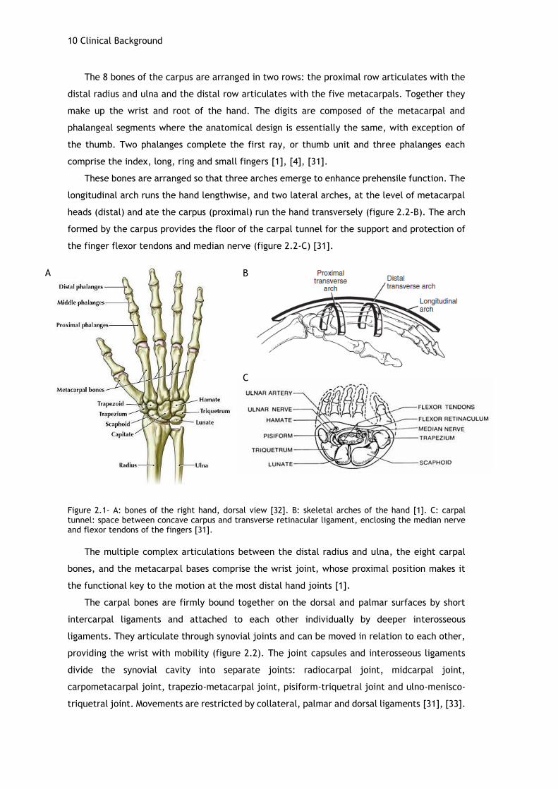
The wrist and hand skeleton are composed by 27 bones, as seen in figure 2.1-A. These
bones are commonly classified into units known as phalanges, metacarpus and carpus [31].
10 Clinical Background
The 8 bones of the carpus are arranged in two rows: the proximal row articulates with the
distal radius and ulna and the distal row articulates with the five metacarpals. Together they
make up the wrist and root of the hand. The digits are composed of the metacarpal and
phalangeal segments where the anatomical design is essentially the same, with exception of
the thumb. Two phalanges complete the first ray, or thumb unit and three phalanges each
comprise the index, long, ring and small fingers [1], [4], [31].
These bones are arranged so that three arches emerge to enhance prehensile function. The
longitudinal arch runs the hand lengthwise, and two lateral arches, at the level of metacarpal
heads (distal) and ate the carpus (proximal) run the hand transversely (figure 2.2-B). The arch
formed by the carpus provides the floor of the carpal tunnel for the support and protection of
the finger flexor tendons and median nerve (figure 2.2-C) [31].
Figure 2.1- A: bones of the right hand, dorsal view [32]. B: skeletal arches of the hand [1]. C: carpal tunnel: space between concave carpus and transverse retinacular ligament, enclosing the median nerve and flexor tendons of the fingers [31].
The multiple complex articulations between the distal radius and ulna, the eight carpal
bones, and the metacarpal bases comprise the wrist joint, whose proximal position makes it
the functional key to the motion at the most distal hand joints [1].
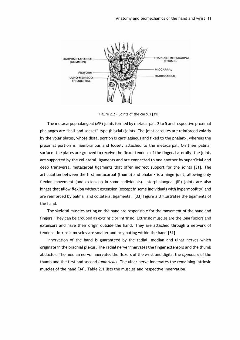
The carpal bones are firmly bound together on the dorsal and palmar surfaces by short
intercarpal ligaments and attached to each other individually by deeper interosseous
ligaments. They articulate through synovial joints and can be moved in relation to each other,
providing the wrist with mobility (figure 2.2). The joint capsules and interosseous ligaments
divide the synovial cavity into separate joints: radiocarpal joint, midcarpal joint,
carpometacarpal joint, trapezio-metacarpal joint, pisiform-triquetral joint and ulno-menisco-
triquetral joint. Movements are restricted by collateral, palmar and dorsal ligaments [31], [33].
A B
C
Anatomy and biomechanics of the hand and wrist 11
Figure 2.2 - Joints of the carpus [31].
The metacarpophalangeal (MP) joints formed by metacarpals 2 to 5 and respective proximal
phalanges are “ball-and-socket” type (biaxial) joints. The joint capsules are reinforced volarly
by the volar plates, whose distal portion is cartilaginous and fixed to the phalanx, whereas the
proximal portion is membranous and loosely attached to the metacarpal. On their palmar
surface, the plates are grooved to receive the flexor tendons of the finger. Laterally, the joints
are supported by the collateral ligaments and are connected to one another by superficial and
deep transversal metacarpal ligaments that offer indirect support for the joints [31]. The
articulation between the first metacarpal (thumb) and phalanx is a hinge joint, allowing only
flexion movement (and extension in some individuals). Interphalangeal (IP) joints are also
hinges that allow flexion without extension (except in some individuals with hypermobility) and
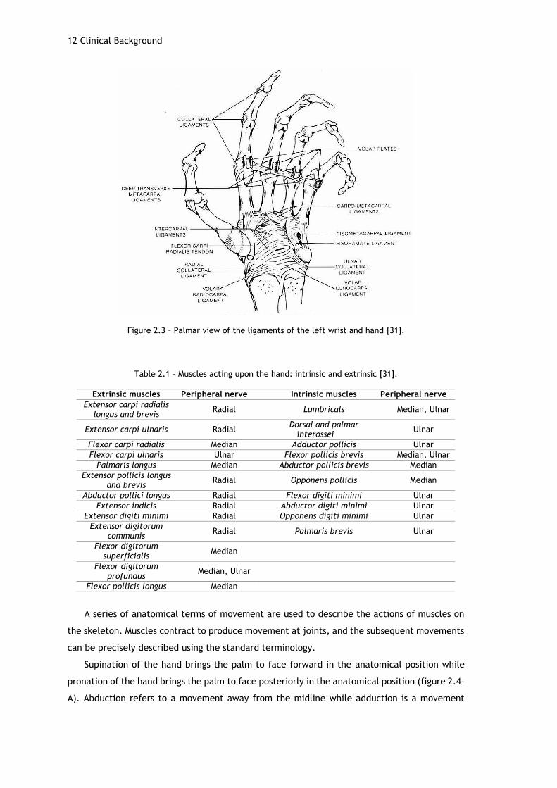
are reinforced by palmar and collateral ligaments. [33] Figure 2.3 illustrates the ligaments of
the hand.
The skeletal muscles acting on the hand are responsible for the movement of the hand and
fingers. They can be grouped as extrinsic or intrinsic. Extrinsic muscles are the long flexors and
extensors and have their origin outside the hand. They are attached through a network of
tendons. Intrinsic muscles are smaller and originating within the hand [31].
Innervation of the hand is guaranteed by the radial, median and ulnar nerves which
originate in the brachial plexus. The radial nerve innervates the finger extensors and the thumb
abductor. The median nerve innervates the flexors of the wrist and digits, the opponens of the
thumb and the first and second lumbricals. The ulnar nerve innervates the remaining intrinsic
muscles of the hand [34]. Table 2.1 lists the muscles and respective innervation.
12 Clinical Background
Figure 2.3 – Palmar view of the ligaments of the left wrist and hand [31].
Table 2.1 – Muscles acting upon the hand: intrinsic and extrinsic [31].
A series of anatomical terms of movement are used to describe the actions of muscles on
the skeleton. Muscles contract to produce movement at joints, and the subsequent movements
can be precisely described using the standard terminology.
Supination of the hand brings the palm to face forward in the anatomical position while
pronation of the hand brings the palm to face posteriorly in the anatomical position (figure 2.4–
A). Abduction refers to a movement away from the midline while adduction is a movement
Extrinsic muscles Peripheral nerve Intrinsic muscles Peripheral nerve
Extensor carpi radialis longus and brevis
Radial Lumbricals Median, Ulnar
Extensor carpi ulnaris Radial Dorsal and palmar
interossei Ulnar
Flexor carpi radialis Median Adductor pollicis Ulnar
Flexor carpi ulnaris Ulnar Flexor pollicis brevis Median, Ulnar
Palmaris longus Median Abductor pollicis brevis Median
Extensor pollicis longus and brevis
Radial Opponens pollicis Median
Abductor pollici longus Radial Flexor digiti minimi Ulnar
Extensor indicis Radial Abductor digiti minimi Ulnar
Extensor digiti minimi Radial Opponens digiti minimi Ulnar
Extensor digitorum communis
Radial Palmaris brevis Ulnar
Flexor digitorum superficialis
Median
Flexor digitorum profundus
Median, Ulnar
Flexor pollicis longus Median

Anatomy and biomechanics of the hand and wrist 13
towards the midline. When referring to the fingers, the midline is that of the hand, thus
abducting the fingers spreads them out (figure 2.4–E) [35], [36].
The wrist joint moves along two axes: anteroposterior for ulnar and radial deviation, and
transverse for flexion and extension (figure 2.4–C,D). The range of motion for radial deviation
is 15-20◦, whereas ulnar deviation has an amplitude of 30-40◦. Range of motion for flexion is of
75-85◦ and extension 70-80◦. The wrist is in a neutral position between flexion and extension,
and radial and ulnar deviation [31].
Figure 2.4 - Movements of the hand and forearm. A: forearm pronation and supination. B: radial and ulnar deviation of the hand. C: wrist flexion and extension. D: flexion, extension and hyper-extension of finger related to MCP joint. E: fingers abduction and adduction (adapted from [37]).
A biomechanical description of the generated moments of the wrist and surrounding
muscles, regarding the flexion, extension, radial and ulnar deviation movements is listed in
table 2.2. Understanding these characteristics is useful for several purposes such a design
tendon transfer surgeries and analyze neurologic and musculoskeletal disorders like carpal
tunnel syndrome and osteoarthritis [38].
A
C
D
B
E
14 Clinical Background
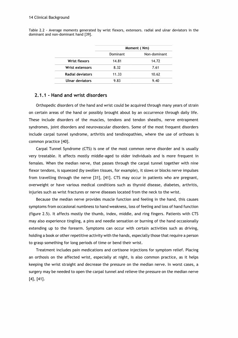
Table 2.2 - Average moments generated by wrist flexors, extensors. radial and ulnar deviators in the dominant and non-dominant hand [39].
2.1.1 - Hand and wrist disorders
Orthopedic disorders of the hand and wrist could be acquired through many years of strain
on certain areas of the hand or possibly brought about by an occurrence through daily life.
These include disorders of the muscles, tendons and tendon sheaths, nerve entrapment
syndromes, joint disorders and neurovascular disorders. Some of the most frequent disorders
include carpal tunnel syndrome, arthritis and tendinopathies, where the use of orthoses is
common practice [40].
Carpal Tunnel Syndrome (CTS) is one of the most common nerve disorder and is usually
very treatable. It affects mostly middle-aged to older individuals and is more frequent in
females. When the median nerve, that passes through the carpal tunnel together with nine
flexor tendons, is squeezed (by swollen tissues, for example), it slows or blocks nerve impulses
from travelling through the nerve [31], [41]. CTS may occur in patients who are pregnant,
overweight or have various medical conditions such as thyroid disease, diabetes, arthritis,
injuries such as wrist fractures or nerve diseases located from the neck to the wrist.
Because the median nerve provides muscle function and feeling in the hand, this causes
symptoms from occasional numbness to hand weakness, loss of feeling and loss of hand function
(figure 2.5). It affects mostly the thumb, index, middle, and ring fingers. Patients with CTS
may also experience tingling, a pins and needle sensation or burning of the hand occasionally
extending up to the forearm. Symptoms can occur with certain activities such as driving,
holding a book or other repetitive activity with the hands, especially those that require a person
to grasp something for long periods of time or bend their wrist.
Treatment includes pain medications and cortisone injections for symptom relief. Placing
an orthosis on the affected wrist, especially at night, is also common practice, as it helps
keeping the wrist straight and decrease the pressure on the median nerve. In worst cases, a
surgery may be needed to open the carpal tunnel and relieve the pressure on the median nerve
[4], [41].
Moment ( Nm)
Dominant Non-dominant
Wrist flexors 14.81 14.72
Wrist extensors 8.32 7.61
Radial deviators 11.33 10.62
Ulnar deviators 9.83 9.40
Anatomy and biomechanics of the hand and wrist 15
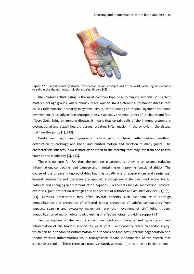
Figure 2.5 – Carpal tunnel syndrome: the median nerve is compressed at the wrist, resulting in numbness or pain in the thumb, index, middle and ring fingers [42].
Rheumatoid arthritis (RA) is the most common type of autoimmune arthritis. It is affect
mostly older age groups, where about 75% are women. RA is a chronic autoimmune disease that
causes inflammation primarily in synovial tissue, often leading to tendon, ligament and bone
involvement. It usually affects multiple joints, especially the small joints of the hands and feet
(figure 2.6). Being an immune disease, it means that certain cells of the immune system are
dysfunctional and attack healthy tissues, creating inflammation in the synovium, the tissues
that line the joints [1], [43].
Predominant signs and symptoms include pain, stiffness, inflammation, swelling,
destruction of cartilage and bone, and limited motion and function of many joints. The
characteristic stiffness in RA is most often worst in the morning that may last from one to two
hours to the whole day [3], [43].
There is no cure for RA, thus the goal for treatment is relieving symptoms, reducing
inflammation, controlling joint damage and maintaining or improving functional ability. The
course of the disease is unpredictable, but it is usually one of aggravations and remissions.
Several treatments and therapies are applied, although no single treatment works for all
patients and changing in treatment often happens. Treatments include medication, physical
exercises, joint protection strategies and application of orthoses and assistive devices. [1], [5],
[43]. Orthosis prescription may offer several benefits such as: pain relief through
immobilization and protection of affected joints; protection of painful contractures from
impacts, scarring and excessive movement; promote movement of stiff joint through
immobilization of more mobile joints; resting of affected joints; providing support [3].
Tendon injuries of the wrist are common conditions characterized by irritation and
inflammation of the tendons around the wrist joint. Tendinopathy refers to tendon injury,
which can be a tendonitis (inflammation of a tendon) or tendinosis (chronic degeneration of a
tendon without inflammation) while tenosynovitis means inflammation of the sheath that
surrounds a tendon. These terms are usually related, as small injuries or tears in the tendon

16 Clinical Background
Figure 2.6 – Comparison between normal and arthritic wrist and hand. Diseased joints are inflamed and damaged [44].
can cause some inflammation and, in a longer term and due to overuse, it can lead to tendon
damage [45]. Tendinopathies are more common in middle-aged adults, and particularly those
who practice sports. These injuries typically occur when tendons are overused, for example,
after practicing sports or due to repetitive movements often found in the workplace like writing
or typing, therefore being considered a work-related disease [40]. Other causes for
tendinopathy and tenosynovitis are arthritis (causing tendon inflammation) and infection.
The tendons surrounding the wrist are divided by those of the back of the wrist (extensors)
and those in front of the wrist (flexors). Any tendon can become symptomatic, but tendonitis
occurs more commonly in a few specific tendons as a result of the anatomy and specific
activities. One example is DeQuervain’s tenosynovitis, which occurs due to the inflammation
of the tendon at the base of the thumb [46].
Symptoms include pain, swelling around the wrist, warmth of the corresponding area and
grinding sensations with movement of the tendons. Treatment includes immobilization of the
affected area, application of ice, medication, physiotherapy and surgery. The use of an orthotic
device, a firm bandage or a brace may be used to guarantee that the wrist and hand stay in
the same position for some time to allow the rest of the affected tendon and decrease
inflammation [45], [46].
2.2 - Orthotics in rehabilitation
2.2.1 - Classification of orthoses in hand dysfunction
There are many ways to classify orthoses, following different types of classification
systems. However, there is not a consensus in terminology, leading to the use of different
Orthotics in rehabilitation 17
systems according to region, country or preferences. In Portugal, the terminology is not
consensual as well [47]. In an effort to normalize the nomenclature for orthotic devices, four
main classification systems were proposed, and generally accepted and utilized. They are:
eponym, acronym, descriptive classification system, and the classification system proposed by
the American Society of Hand Therapists (ASHT). These systems include the use of routine
memory or logical deduction in grouping of orthoses, although there isn’t a clear best one [48].
Eponym classification is based on the author’s name, for example Capener splint. It implies a
clear and descriptive knowledge of each name, making the introduction of alterations into the
model difficult. The acronym classification system, adopted by ISO (International Organization
for Standardization) and used in most countries, consists in the combination of the first letters
of the involved joints or segments, for example “WHO”: wrist-hand orthosis [47].
Descriptive classification system describes orthoses based on the following criteria: types
of forces applied and respective spatial plane, anatomic site and primary kinematic purpose of
the orthosis. Although, more detailed, it is not straightforward enough, leading to
communication difficulties [47]. In an effort to reduce the discrepancies in terminology the
ASHT developed the Splint Classification System (SCS). Based on splint function rather than
splint form, the SCS describes upper limb splints through a series of predefined divisions that
define orthoses’ technical names [47], [49]. Since this system provides a more complete and
objective description, its components will be more thoroughly examined.
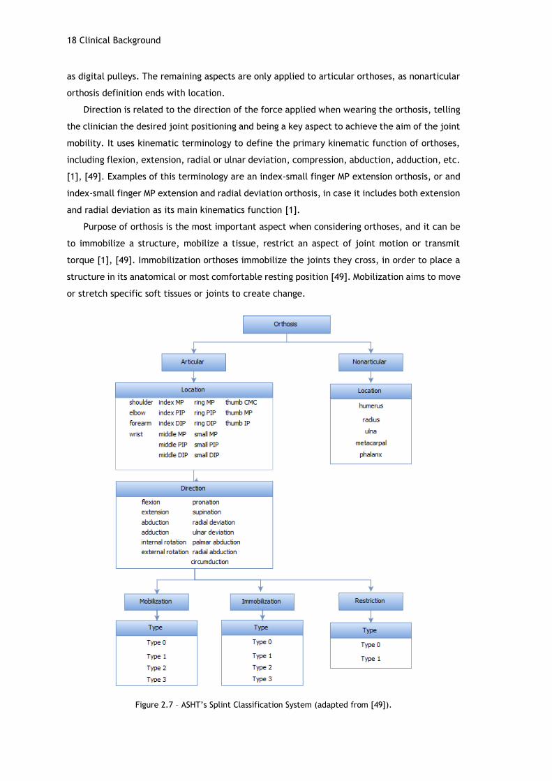
The SCS (figure 2.7) includes identification of articular/nonarticular, location, direction,
purpose and type of orthoses. This description provides clinicians a clear concept of the looks
and function of the orthosis [49].
Articular and nonarticular orthoses are two definitions that separate orthoses in two
groups, according to the way they interact with joints. Articular orthoses, are the most common
type of orthosis, and are the ones that cross a joint or series of joints, and use a three-point
pressure system to affect the joint/joints through restriction, immobilization, mobilization, or
transmission of torque. As most splints are articular, the term “articular” is not included in the
technical name, since it is assumed. Examples are the wrist immobilization orthosis and elbow
flexion restriction orthosis. Nonarticular orthoses apply two-point pressure forces to stabilize
or immobilize isolated body segments. The term “nonarticular” is included in the designation
of the orthosis. The nonarticular humerus orthosis, nonarticular metacarpal orthosis and
fracture othoses are some examples [1], [49].
Location relates to the specific body part or joint where the orthosis is applied, whereas
the primary joint is the target joint and the secondary joints are added for protection,
stabilization or comfort [49]. In an articular orthosis context, location points to the joints that
are the main focus of the orthosis, for example shoulder or thumb. Regarding nonarticular
splints, location identifies a bone, such as humerus or phalanx, or soft tissue structures such
18 Clinical Background
as digital pulleys. The remaining aspects are only applied to articular orthoses, as nonarticular
orthosis definition ends with location.
Direction is related to the direction of the force applied when wearing the orthosis, telling
the clinician the desired joint positioning and being a key aspect to achieve the aim of the joint
mobility. It uses kinematic terminology to define the primary kinematic function of orthoses,
including flexion, extension, radial or ulnar deviation, compression, abduction, adduction, etc.
[1], [49]. Examples of this terminology are an index-small finger MP extension orthosis, or and
index-small finger MP extension and radial deviation orthosis, in case it includes both extension
and radial deviation as its main kinematics function [1].
Purpose of orthosis is the most important aspect when considering orthoses, and it can be
to immobilize a structure, mobilize a tissue, restrict an aspect of joint motion or transmit
torque [1], [49]. Immobilization orthoses immobilize the joints they cross, in order to place a
structure in its anatomical or most comfortable resting position [49]. Mobilization aims to move
or stretch specific soft tissues or joints to create change.
Figure 2.7 – ASHT’s Splint Classification System (adapted from [49]).
Orthotics in rehabilitation 19
When steady tension is applied through the orthosis over time, the living cells of the
contracted tissues are stimulated to grow oriented in the direction of tension [49]–[51].
Restriction orthoses restrict or limit an aspect of joint motion. Figure 2.8 shows examples of
orthoses with different purposes.
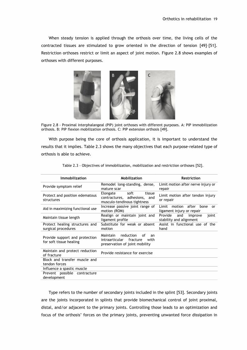
Figure 2.8 - Proximal interphalangeal (PIP) joint orthoses with different purposes. A: PIP immobilization orthosis. B: PIP flexion mobilization orthosis. C: PIP extension orthosis [49].
With purpose being the core of orthosis application, it is important to understand the
results that it implies. Table 2.3 shows the many objectives that each purpose-related type of
orthosis is able to achieve.
Table 2.3 - Objectives of immobilization, mobilization and restriction orthoses [52].
Type refers to the number of secondary joints included in the splint [53]. Secondary joints
are the joints incorporated in splints that provide biomechanical control of joint proximal,
distal, and/or adjacent to the primary joints. Controlling those leads to an optimization and
focus of the orthosis’ forces on the primary joints, preventing unwanted force dissipation in
A
B
C
Immobilization Mobilization Restriction
Provide symptom relief Remodel long-standing, dense, mature scar
Limit motion after nerve injury or repair
Protect and position edematous structures
Elongate soft tissue contractures, adhesions, and musculo-tendinous tightness
Limit motion after tendon injury or repair
Aid in maximizing functional use Increase passive joint range of motion (ROM)
Limit motion after bone or ligament injury or repair
Maintain tissue length Realign or maintain joint and ligament profile
Provide and improve joint stability and alignment
Protect healing structures and surgical procedures
Substitute for weak or absent motion
Assist in functional use of the hand
Provide support and protection for soft tissue healing
Maintain reduction of an intraarticular fracture with preservation of joint mobility
Maintain and protect reduction of fracture
Provide resistance for exercise
Block and transfer muscle and tendon forces
Influence a spastic muscle
Prevent possible contracture development
20 Clinical Background
joints that are not primary. Type is diagnosis specific, often separating similar orthoses
according to the diagnosis requirements [1].
When designing an orthotic device, another common terminology, non-SCS nomenclature,
is frequently used for immobilizing/mobilizing orthoses: static, serial static, dynamic and static
progressive [49]. These terms regard the biomechanical principles of orthoses, since the design
of an orthosis must take into consideration the mechanical laws of force application [47].
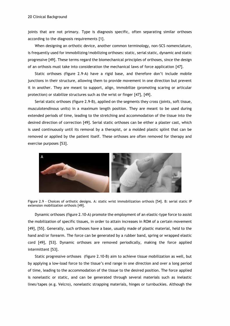
Static orthoses (figure 2.9-A) have a rigid base, and therefore don’t include mobile
junctions in their structure, allowing them to provide movement in one direction but prevent
it in another. They are meant to support, align, immobilize (promoting scaring or articular
protection) or stabilize structures such as the wrist or finger [47], [49].
Serial static orthoses (figure 2.9-B), applied on the segments they cross (joints, soft tissue,
musculotendinous units) in a maximum length position. They are meant to be used during
extended periods of time, leading to the stretching and accommodation of the tissue into the
desired direction of correction [49]. Serial static orthoses can be either a plaster cast, which
is used continuously until its removal by a therapist, or a molded plastic splint that can be
removed or applied by the patient itself. These orthoses are often removed for therapy and
exercise purposes [53].
Figure 2.9 - Choices of orthotic designs. A: static wrist immobilization orthosis [54]. B: serial static IP extension mobilization orthosis [49].
Dynamic orthoses (figure 2.10-A) promote the employment of an elastic-type force to assist
the mobilization of specific tissues, in order to attain increases in ROM of a certain movement
[49], [55]. Generally, such orthoses have a base, usually made of plastic material, held to the
hand and/or forearm. The force can be generated by a rubber band, spring or wrapped elastic
cord [49], [53]. Dynamic orthoses are removed periodically, making the force applied
intermittent [53].
Static progressive orthoses (figure 2.10-B) aim to achieve tissue mobilization as well, but
by applying a low-load force to the tissue’s end range in one direction and over a long period
of time, leading to the accommodation of the tissue to the desired position. The force applied
is nonelastic or static, and can be generated through several materials such as inelastic
lines/tapes (e.g. Velcro), nonelastic strapping materials, hinges or turnbuckles. Although the
A B

Orthotics in rehabilitation 21
force applied is smaller, the amount of tension is variable and adjustable by the patient or
therapist, allowing the tissue to accommodate gradually to the tension [49], [53], [56], [57].
Figure 2.10 - Choices of orthotic designs. A: dynamic MCP extension orthosis [58]. B: static progressive
PIP extension orthosis [59].
Regarding wrist dysfunction, particularly CTS and RA, one of the required orthosis can be
referred as a wrist neutral immobilization orthosis of type 0, according to SCS, and considered
as a static orthosis [1].
2.2.2 - Conventional methods for fabrication of orthoses
Orthotic devices can be prefabricated or custom-made. Prefabricated “off-the-shelf”
orthoses can be bought from a variety of establishments such as pharmacies, and are prescribed
by orthotic therapists. These devices come in a range of pre-established sizes, therefore
assuming a “one-size-fits-all” strategy. Although easier to obtain, this strategy does not
necessarily fit for each individual’s unique features, unless adjusted by the user or orthotic
professionals. On the other hand, custom-made orthoses are produced and distributed by
orthotic practitioners to fit each patient’s lifestyle and specific anatomical demands, thus
resulting in a superior fit and comfort. They are also suitable for extreme size or uncommon
deformities, that aren’t addressed by prefabricated orthoses [2].
Numerous companies market and distribute supplies for orthotic fabrication, including
many types of thermoplastic material, strapping, component systems, and equipment [47],
[49]. Since extreme or uncommon conditions will always exist, there will always be the need
for custom-made orthoses [1], [2], [47], [49].
Custom-made orthoses are typically handmade [2]. Low-temperature thermoplastics (LTT)
are the most commonly used materials to fabricate custom orthoses and are sold in sheets or
precut designs [49].
There are two main approaches for obtaining custom orthoses. The first one implies the
manufacturing of a negative plaster cast that is filled with plaster to produce a model that is
a copy of the original part. This plaster copy is used for the formation of thermoplastic material
like polyethylene (PE) or CPP, manually or by vacuum (figure 2.11-A,B). The formed plastic
shell is then cut to the desired shape and finished with padding and fastening straps [11].
A B
22 Clinical Background
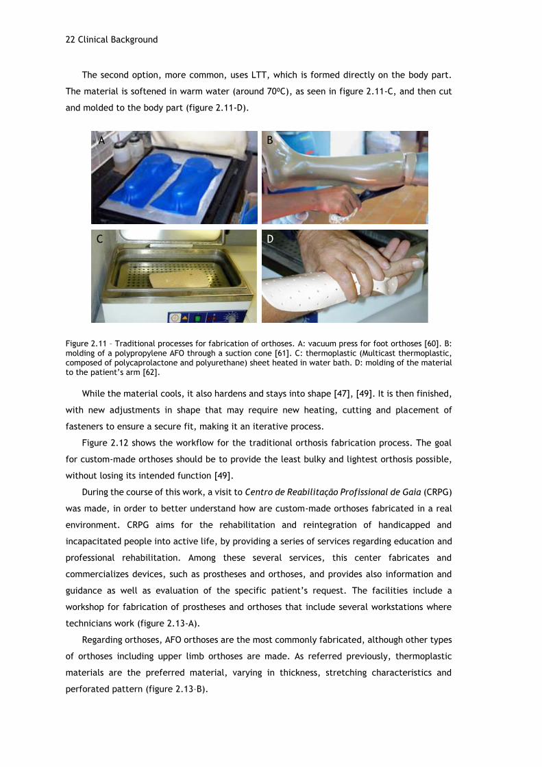
The second option, more common, uses LTT, which is formed directly on the body part.
The material is softened in warm water (around 70⁰C), as seen in figure 2.11-C, and then cut
and molded to the body part (figure 2.11-D).
Figure 2.11 – Traditional processes for fabrication of orthoses. A: vacuum press for foot orthoses [60]. B: molding of a polypropylene AFO through a suction cone [61]. C: thermoplastic (Multicast thermoplastic, composed of polycaprolactone and polyurethane) sheet heated in water bath. D: molding of the material to the patient’s arm [62].
While the material cools, it also hardens and stays into shape [47], [49]. It is then finished,
with new adjustments in shape that may require new heating, cutting and placement of
fasteners to ensure a secure fit, making it an iterative process.
Figure 2.12 shows the workflow for the traditional orthosis fabrication process. The goal
for custom-made orthoses should be to provide the least bulky and lightest orthosis possible,
without losing its intended function [49].
During the course of this work, a visit to Centro de Reabilitação Profissional de Gaia (CRPG)
was made, in order to better understand how are custom-made orthoses fabricated in a real
environment. CRPG aims for the rehabilitation and reintegration of handicapped and
incapacitated people into active life, by providing a series of services regarding education and
professional rehabilitation. Among these several services, this center fabricates and
commercializes devices, such as prostheses and orthoses, and provides also information and
guidance as well as evaluation of the specific patient’s request. The facilities include a
workshop for fabrication of prostheses and orthoses that include several workstations where
technicians work (figure 2.13-A).
Regarding orthoses, AFO orthoses are the most commonly fabricated, although other types
of orthoses including upper limb orthoses are made. As referred previously, thermoplastic
materials are the preferred material, varying in thickness, stretching characteristics and
perforated pattern (figure 2.13–B).
A B
C D
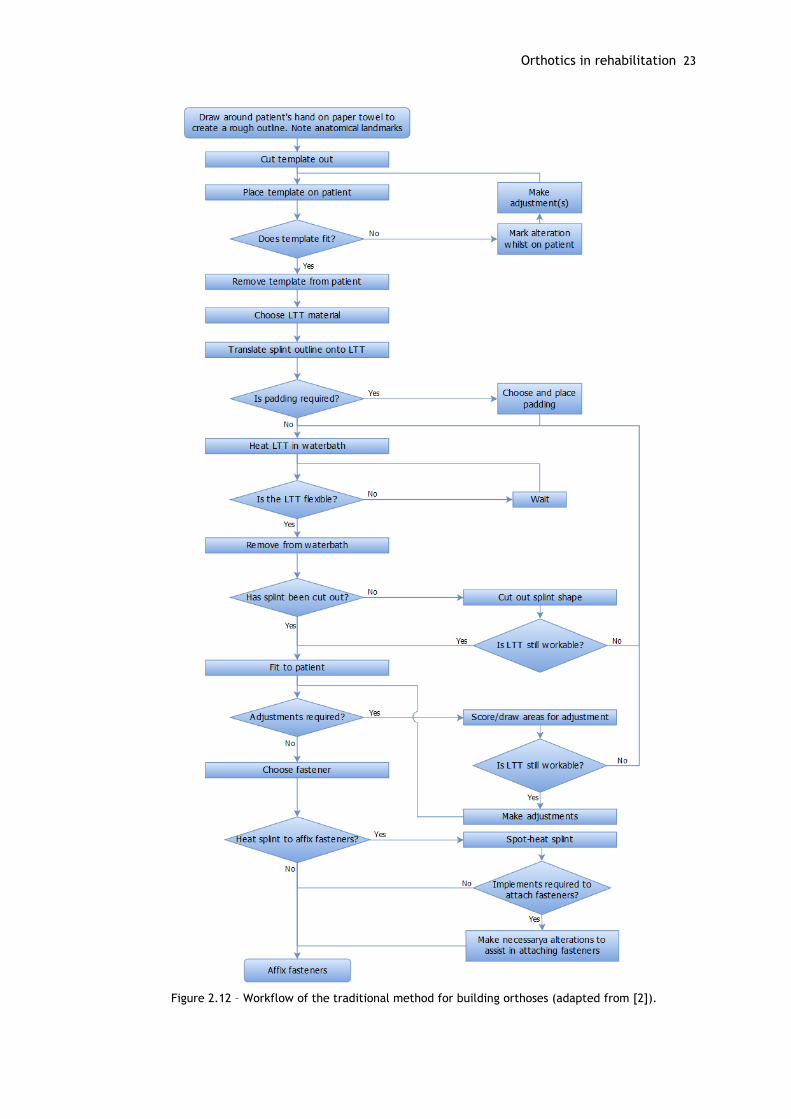
Orthotics in rehabilitation 23
Figure 2.12 – Workflow of the traditional method for building orthoses (adapted from [2]).
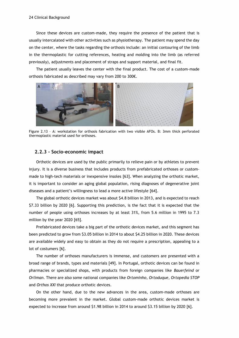
24 Clinical Background
A B
Since these devices are custom-made, they require the presence of the patient that is
usually intercalated with other activities such as physiotherapy. The patient may spend the day
on the center, where the tasks regarding the orthosis include: an initial contouring of the limb
in the thermoplastic for cutting references, heating and molding into the limb (as referred
previously), adjustments and placement of straps and support material, and final fit.
The patient usually leaves the center with the final product. The cost of a custom-made
orthosis fabricated as described may vary from 200 to 300€.
Figure 2.13 – A: workstation for orthosis fabrication with two visible AFOs. B: 3mm thick perforated thermoplastic material used for orthoses.
2.2.3 - Socio-economic impact
Orthotic devices are used by the public primarily to relieve pain or by athletes to prevent
injury. It is a diverse business that includes products from prefabricated orthoses or custom-
made to high-tech materials or inexpensive insoles [63]. When analyzing the orthotic market,
it is important to consider an aging global population, rising diagnoses of degenerative joint
diseases and a patient’s willingness to lead a more active lifestyle [64].
The global orthotic devices market was about $4.8 billion in 2013, and is expected to reach
$7.33 billion by 2020 [6]. Supporting this prediction, is the fact that it is expected that the
number of people using orthoses increases by at least 31%, from 5.6 million in 1995 to 7.3
million by the year 2020 [65].
Prefabricated devices take a big part of the orthotic devices market, and this segment has
been predicted to grow from $3.05 billion in 2014 to about $4.25 billion in 2020. These devices
are available widely and easy to obtain as they do not require a prescription, appealing to a
lot of costumers [6].
The number of orthoses manufacturers is immense, and customers are presented with a
broad range of brands, types and materials [49]. In Portugal, orthotic devices can be found in
pharmacies or specialized shops, with products from foreign companies like Bauerfeind or
Orliman. There are also some national companies like Ortominho, Ortoduque, Ortopedia STOP
and Orthos XXI that produce orthotic devices.
On the other hand, due to the new advances in the area, custom-made orthoses are
becoming more prevalent in the market. Global custom-made orthotic devices market is
expected to increase from around $1.98 billion in 2014 to around $3.15 billion by 2020 [6].

Orthotics in rehabilitation 25
The market for orthotic devices has experienced some changes over the past years. The
growing demand for affordable and efficient orthoses has led to a number of innovations in the
orthotic device industry. The development of modern modelling and manufacturing techniques,
such as the use of 3D printers, the improvement of measurement and analysis techniques, and
continuous research of materials gives AM an emerging role in the industry [6], [66].
The adoption of AM technology in the orthotic industry may result in a decrease of overall
costs and time for the process of obtaining and maintaining an orthosis. In current practice,
duplicating orthoses implies repeating the whole process for each orthosis. Using CAD and AM,
duplicating orthoses may result in material cost only. Time and travel costs of both patient and
clinician are also decreased, since there is no need for the patient to attend another session,
reducing time spent on clinics and patient waiting lists and improving satisfaction in the health-
care system [2]. However, the orthotic industry is not familiar with engineering. Two biggest
obstacles that contemporary orthotics face are educating and informing the new CAD/CAE user
and implementing the system in an existing clinical setting [67].
The rise for demand of orthotic devices, allied to an increasing number of diseases and
disorders, and the technological innovations in this area will improve the sophistication of
treatment that is becoming more and more individualized and efficient.

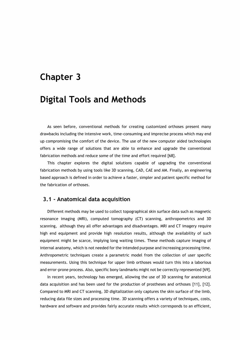
Chapter 3
Digital Tools and Methods
As seen before, conventional methods for creating customized orthoses present many
drawbacks including the intensive work, time-consuming and imprecise process which may end
up compromising the comfort of the device. The use of the new computer aided technologies
offers a wide range of solutions that are able to enhance and upgrade the conventional
fabrication methods and reduce some of the time and effort required [68].
This chapter explores the digital solutions capable of upgrading the conventional
fabrication methods by using tools like 3D scanning, CAD, CAE and AM. Finally, an engineering
based approach is defined in order to achieve a faster, simpler and patient specific method for
the fabrication of orthoses.
3.1 - Anatomical data acquisition
Different methods may be used to collect topographical skin surface data such as magnetic
resonance imaging (MRI), computed tomography (CT) scanning, anthropometrics and 3D
scanning, although they all offer advantages and disadvantages. MRI and CT imagery require
high end equipment and provide high resolution results, although the availability of such
equipment might be scarce, implying long waiting times. These methods capture imaging of
internal anatomy, which is not needed for the intended purpose and increasing processing time.
Anthropometric techniques create a parametric model from the collection of user specific
measurements. Using this technique for upper limb orthoses would turn this into a laborious
and error-prone process. Also, specific bony landmarks might not be correctly represented [69].
In recent years, technology has emerged, allowing the use of 3D scanning for anatomical
data acquisition and has been used for the production of prostheses and orthoses [11], [12].
Compared to MRI and CT scanning, 3D digitalization only captures the skin surface of the limb,
reducing data file sizes and processing time. 3D scanning offers a variety of techniques, costs,
hardware and software and provides fairly accurate results which corresponds to an efficient,
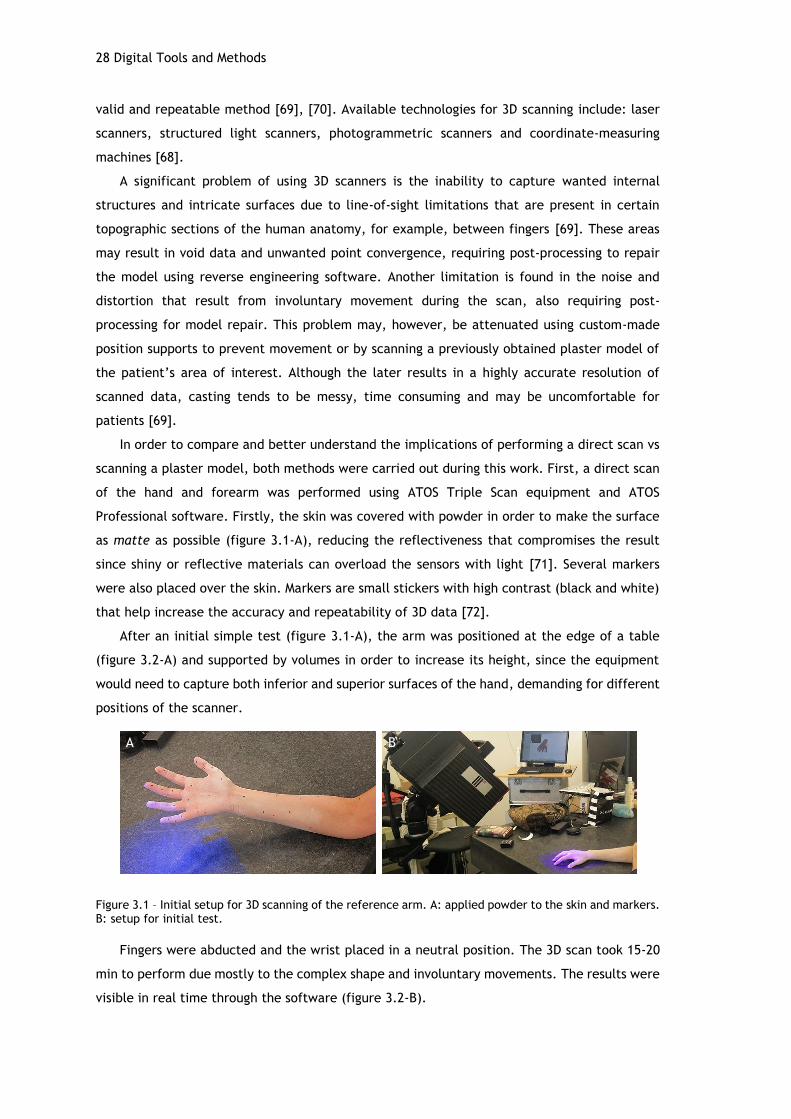
28 Digital Tools and Methods
valid and repeatable method [69], [70]. Available technologies for 3D scanning include: laser
scanners, structured light scanners, photogrammetric scanners and coordinate-measuring
machines [68].
A significant problem of using 3D scanners is the inability to capture wanted internal
structures and intricate surfaces due to line-of-sight limitations that are present in certain
topographic sections of the human anatomy, for example, between fingers [69]. These areas
may result in void data and unwanted point convergence, requiring post-processing to repair
the model using reverse engineering software. Another limitation is found in the noise and
distortion that result from involuntary movement during the scan, also requiring post-
processing for model repair. This problem may, however, be attenuated using custom-made
position supports to prevent movement or by scanning a previously obtained plaster model of
the patient’s area of interest. Although the later results in a highly accurate resolution of
scanned data, casting tends to be messy, time consuming and may be uncomfortable for
patients [69].
In order to compare and better understand the implications of performing a direct scan vs
scanning a plaster model, both methods were carried out during this work. First, a direct scan
of the hand and forearm was performed using ATOS Triple Scan equipment and ATOS
Professional software. Firstly, the skin was covered with powder in order to make the surface
as matte as possible (figure 3.1-A), reducing the reflectiveness that compromises the result
since shiny or reflective materials can overload the sensors with light [71]. Several markers
were also placed over the skin. Markers are small stickers with high contrast (black and white)
that help increase the accuracy and repeatability of 3D data [72].
After an initial simple test (figure 3.1-A), the arm was positioned at the edge of a table
(figure 3.2-A) and supported by volumes in order to increase its height, since the equipment
would need to capture both inferior and superior surfaces of the hand, demanding for different
positions of the scanner.
Figure 3.1 – Initial setup for 3D scanning of the reference arm. A: applied powder to the skin and markers. B: setup for initial test.
Fingers were abducted and the wrist placed in a neutral position. The 3D scan took 15-20
min to perform due mostly to the complex shape and involuntary movements. The results were
visible in real time through the software (figure 3.2-B).
A B

Anatomical data acquisition 29
Figure 3.2 - 3D Scan of hand and forearm. A C: position of equipment for superior surface data acquisition. D: Real time software reconstruction.
The use of supports for the position and alignment of the hand would have been helpful,
since after a few minutes it was not possible to control tremors and involuntary movements of
the hand. Despite these issues, the final result, although in need of post-processing, turned out
reasonable and captured the intended anatomic landmarks.
To obtain the plaster model of the same hand, an alginate mold was made. For that, a mix
of alginate and water was poured into a plastic container, were the hand was placed in the
same position as described before (figure 3.3-A). After a few minutes of solidification, the hand
was carefully removed from the container and the mold was done. After that, a mixture of
plaster and water was poured into the mold (figure 3.3-B) and let for solidification for about 1
hour. Finally, the alginate and cast were removed from the container, and the alginate was
easily cut and disposed, resulting in a plaster model of the hand (figure 3.3-C). The plaster
model provides a very good representation of the hand and is capable of reproducing fine
details such as creases and pores (figure 3.3-D,E).
Once the plaster model is obtained, a 3D scan may be performed, providing for better
results, since the concerns for involuntary movements are diminished and the fact that plaster
is a rather good material for 3D scanning due to its matte appearance and opacity [69]. Table
3.1 provides a comparison between the direct 3D scan and the scanning of a plaster model
regarding associated time, cost and final result.
Table 3.1 – Comparison of direct and plaster model scanning.
Direct Plaster model
Time 15-20 min About 1h30 to obtain model
Plus scanning time
Cost 0 * Cost of materials (alginate
and plaster)
Result Reasonable, requires post-
processing Good, requires little post-
processing
* Implies an initial cost of obtaining the equipment.
Although the results aren’t as accurate as the ones provided from the scanning of a plaster
model, the direct scan method is faster, cheaper and simpler and still provides a good enough
result for the intended purpose.
A B
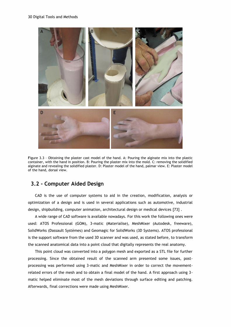
30 Digital Tools and Methods
Figure 3.3 – Obtaining the plaster cast model of the hand. A: Pouring the alginate mix into the plastic container, with the hand in position. B: Pouring the plaster mix into the mold. C: removing the solidified alginate and revealing the solidified plaster. D: Plaster model of the hand, palmar view. E: Plaster model of the hand, dorsal view.
3.2 - Computer Aided Design
CAD is the use of computer systems to aid in the creation, modification, analysis or
optimization of a design and is used in several applications such as automotive, industrial
design, shipbuilding, computer animation, architectural design or medical devices [73] .
A wide range of CAD software is available nowadays. For this work the following ones were
used: ATOS Professional (GOM), 3-matic (Materialise), MeshMixer (Autodesk, freeware),
SolidWorks (Dassault Systèmes) and Geomagic for SolidWorks (3D Systems). ATOS professional
is the support software from the used 3D scanner and was used, as stated before, to transform
the scanned anatomical data into a point cloud that digitally represents the real anatomy.
This point cloud was converted into a polygon mesh and exported as a STL file for further
processing. Since the obtained result of the scanned arm presented some issues, post-
processing was performed using 3-matic and MeshMixer in order to correct the movement-
related errors of the mesh and to obtain a final model of the hand. A first approach using 3-
matic helped eliminate most of the mesh deviations through surface editing and patching.
Afterwards, final corrections were made using MeshMixer.
A B C
D E
Computer Aided Engineering 31
The imported mesh (figure 3.4–A) was transformed from a surface into a solid model, in
order to easily close some of the existent gaps, mostly on the fingers. Some parts of the fingers
required reconstruction, as their surface was not correctly represented, leading to a void were
there should be a surface thus leading to a manual adding of material. The final result provided
a good representation of the anatomical data and the associated measures were representative
of the reference arm (figure 3.4-B,C). Due to SolidWorks restrictions (a maximum of 20000
triangles), the number of triangles of the mesh was then reduced (from 15873 vertices and
31742 triangles to 2979 vertices and 5954 triangles) in order to simplify the geometry and
decrease file weight for further modelling. Although reducing the number of triangles reduces
the details of the mesh, it did not compromise its use for the intended purpose.
Figure 3.4 – Model of scanned arm. A: palmar and dorsal views of the imported mesh from 3-matic to MeshMixer; gaps and overlaps are still visible through the faulty edges (blue). B: palmar view of the final model and corresponding dimensions (147.06x54.31x303.65 mm). C: dorsal view of the final reconstructed model
3.3 - Computer Aided Engineering
CAE uses computer software to simulate performance in order to improve product designs
or assist in the resolution of engineering problems, for a wide range of industries. This includes
simulation, validation and optimization of products, processes and manufacturing tools [74].
A typical CAE process comprises the pre-processing phase, where the geometry is modeled
(through CAD) and the physical properties of the design and environment are defined in the
form of applied loads and constraints. The model is solved (in a simulation) using appropriate
mathematical formulation of the underlying physics and the results are evaluated. The
information acquired by the simulation results help support design teams in decision making.
CAE software support a wide range of engineering disciplines including stress and dynamics
analysis on components and assemblies using FEA, thermal and fluid analysis, mechanical event
simulation, optimization, among others [74], [75].
A B C
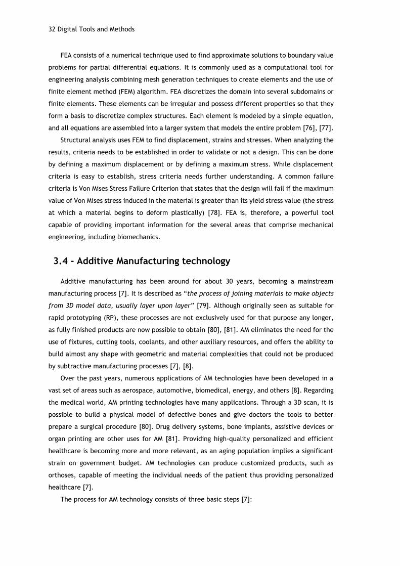
32 Digital Tools and Methods
FEA consists of a numerical technique used to find approximate solutions to boundary value
problems for partial differential equations. It is commonly used as a computational tool for
engineering analysis combining mesh generation techniques to create elements and the use of
finite element method (FEM) algorithm. FEA discretizes the domain into several subdomains or
finite elements. These elements can be irregular and possess different properties so that they
form a basis to discretize complex structures. Each element is modeled by a simple equation,
and all equations are assembled into a larger system that models the entire problem [76], [77].
Structural analysis uses FEM to find displacement, strains and stresses. When analyzing the
results, criteria needs to be established in order to validate or not a design. This can be done
by defining a maximum displacement or by defining a maximum stress. While displacement
criteria is easy to establish, stress criteria needs further understanding. A common failure
criteria is Von Mises Stress Failure Criterion that states that the design will fail if the maximum
value of Von Mises stress induced in the material is greater than its yield stress value (the stress
at which a material begins to deform plastically) [78]. FEA is, therefore, a powerful tool
capable of providing important information for the several areas that comprise mechanical
engineering, including biomechanics.
3.4 - Additive Manufacturing technology
Additive manufacturing has been around for about 30 years, becoming a mainstream
manufacturing process [7]. It is described as “the process of joining materials to make objects
from 3D model data, usually layer upon layer” [79]. Although originally seen as suitable for
rapid prototyping (RP), these processes are not exclusively used for that purpose any longer,
as fully finished products are now possible to obtain [80], [81]. AM eliminates the need for the
use of fixtures, cutting tools, coolants, and other auxiliary resources, and offers the ability to
build almost any shape with geometric and material complexities that could not be produced
by subtractive manufacturing processes [7], [8].
Over the past years, numerous applications of AM technologies have been developed in a
vast set of areas such as aerospace, automotive, biomedical, energy, and others [8]. Regarding
the medical world, AM printing technologies have many applications. Through a 3D scan, it is
possible to build a physical model of defective bones and give doctors the tools to better
prepare a surgical procedure [80]. Drug delivery systems, bone implants, assistive devices or
organ printing are other uses for AM [81]. Providing high-quality personalized and efficient
healthcare is becoming more and more relevant, as an aging population implies a significant
strain on government budget. AM technologies can produce customized products, such as
orthoses, capable of meeting the individual needs of the patient thus providing personalized
healthcare [7].
The process for AM technology consists of three basic steps [7]:
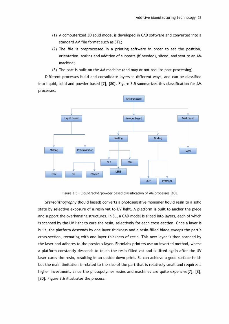
Additive Manufacturing technology 33
(1) A computerized 3D solid model is developed in CAD software and converted into a
standard AM file format such as STL;
(2) The file is preprocessed in a printing software in order to set the position,
orientation, scaling and addition of supports (if needed), sliced, and sent to an AM
machine;
(3) The part is built on the AM machine (and may or not require post-processing).
Different processes build and consolidate layers in different ways, and can be classified
into liquid, solid and powder based [7], [80]. Figure 3.5 summarizes this classification for AM
processes.
Figure 3.5 - Liquid/solid/powder based classification of AM processes [80].
Stereolithography (liquid based) converts a photosensitive monomer liquid resin to a solid
state by selective exposure of a resin vat to UV light. A platform is built to anchor the piece
and support the overhanging structures. In SL, a CAD model is sliced into layers, each of which
is scanned by the UV light to cure the resin, selectively for each cross-section. Once a layer is
built, the platform descends by one layer thickness and a resin-filled blade sweeps the part’s
cross-section, recoating with one layer thickness of resin. This new layer is then scanned by
the laser and adheres to the previous layer. Formlabs printers use an inverted method, where
a platform constantly descends to touch the resin-filled vat and is lifted again after the UV
laser cures the resin, resulting in an upside down print. SL can achieve a good surface finish
but the main limitation is related to the size of the part that is relatively small and requires a
higher investment, since the photopolymer resins and machines are quite expensive[7], [8],
[80]. Figure 3.6 illustrates the process.
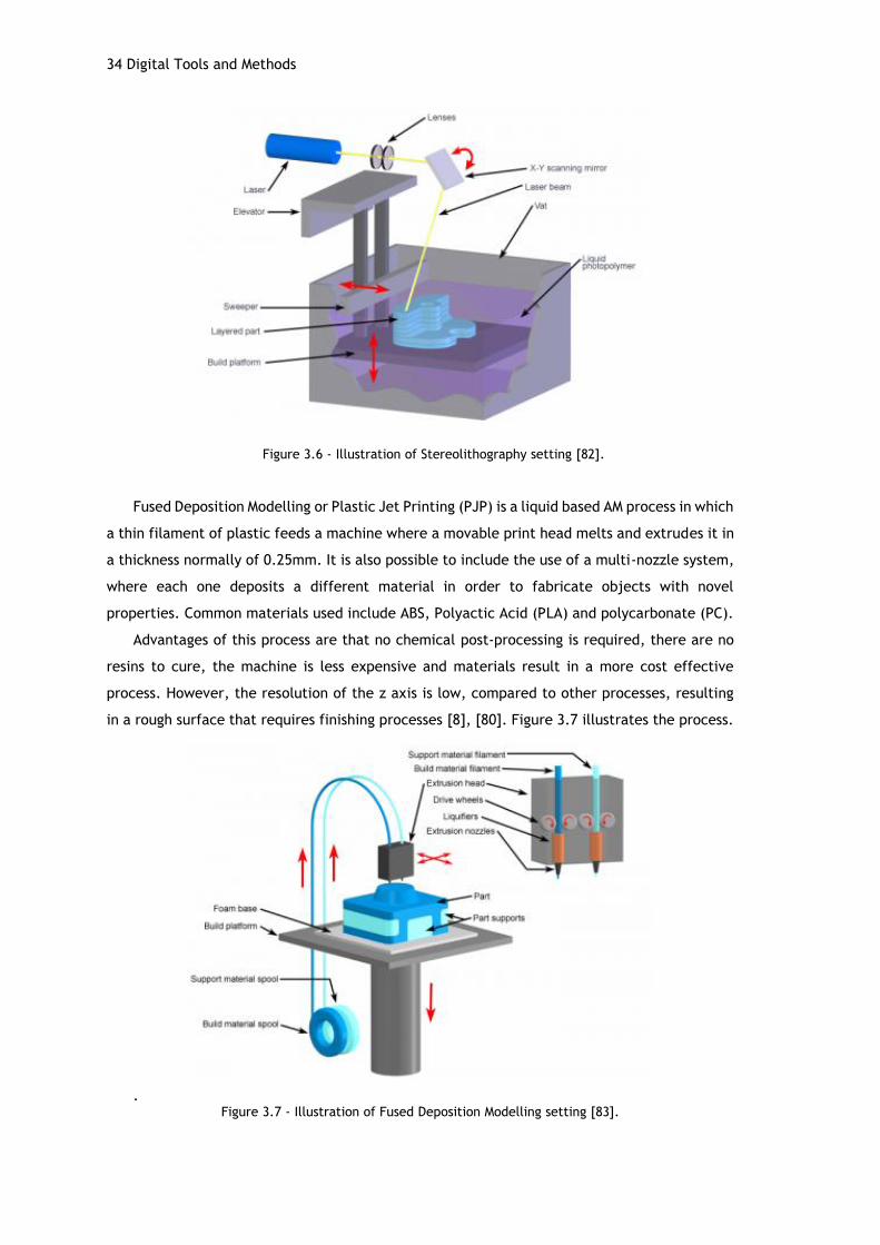
34 Digital Tools and Methods
Figure 3.6 - Illustration of Stereolithography setting [82].
Fused Deposition Modelling or Plastic Jet Printing (PJP) is a liquid based AM process in which
a thin filament of plastic feeds a machine where a movable print head melts and extrudes it in
a thickness normally of 0.25mm. It is also possible to include the use of a multi-nozzle system,
where each one deposits a different material in order to fabricate objects with novel
properties. Common materials used include ABS, Polyactic Acid (PLA) and polycarbonate (PC).
Advantages of this process are that no chemical post-processing is required, there are no
resins to cure, the machine is less expensive and materials result in a more cost effective
process. However, the resolution of the z axis is low, compared to other processes, resulting
in a rough surface that requires finishing processes [8], [80]. Figure 3.7 illustrates the process.
. Figure 3.7 - Illustration of Fused Deposition Modelling setting [83].
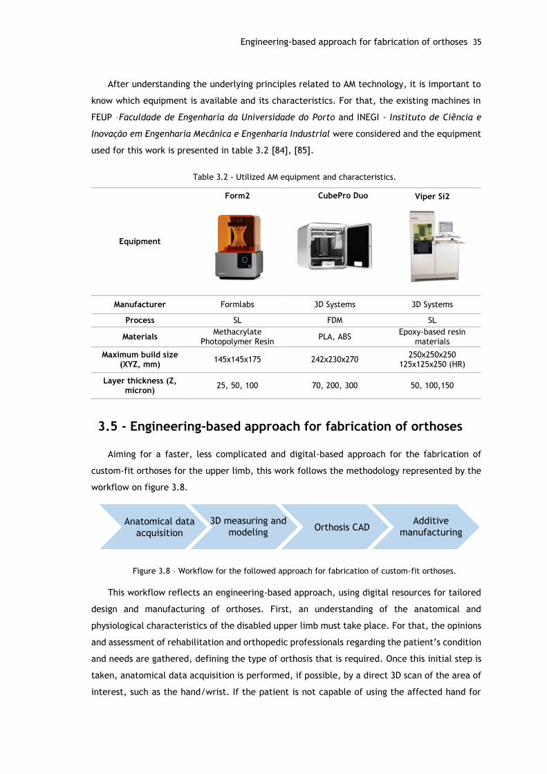
Engineering-based approach for fabrication of orthoses 35
After understanding the underlying principles related to AM technology, it is important to
know which equipment is available and its characteristics. For that, the existing machines in
FEUP –Faculdade de Engenharia da Universidade do Porto and INEGI - Instituto de Ciência e
Inovação em Engenharia Mecânica e Engenharia Industrial were considered and the equipment
used for this work is presented in table 3.2 [84], [85].
Table 3.2 - Utilized AM equipment and characteristics.
Equipment
Form2
CubePro Duo
Viper Si2
Manufacturer Formlabs 3D Systems 3D Systems
Process SL FDM SL
Materials Methacrylate
Photopolymer Resin PLA, ABS
Epoxy-based resin materials
Maximum build size (XYZ, mm)
145x145x175 242x230x270 250x250x250
125x125x250 (HR)
Layer thickness (Z, micron)
25, 50, 100 70, 200, 300 50, 100,150
3.5 - Engineering-based approach for fabrication of orthoses
Aiming for a faster, less complicated and digital-based approach for the fabrication of
custom-fit orthoses for the upper limb, this work follows the methodology represented by the
workflow on figure 3.8.
Figure 3.8 – Workflow for the followed approach for fabrication of custom-fit orthoses.
This workflow reflects an engineering-based approach, using digital resources for tailored
design and manufacturing of orthoses. First, an understanding of the anatomical and
physiological characteristics of the disabled upper limb must take place. For that, the opinions
and assessment of rehabilitation and orthopedic professionals regarding the patient’s condition
and needs are gathered, defining the type of orthosis that is required. Once this initial step is
taken, anatomical data acquisition is performed, if possible, by a direct 3D scan of the area of
interest, such as the hand/wrist. If the patient is not capable of using the affected hand for
Anatomical data
acquisition
3D measuring and
modelingOrthosis CAD
Additive
manufacturing

36 Digital Tools and Methods
the scan, the healthy hand may be scanned in the desired position and then mirrored in the
modelling software. Once the resulting digital representation is obtained, the data is exported
to an STL-editor software and processed in order to clean up possible errors and the
measurements are checked for the specific patient. The model is then used as a guideline for
the design of the orthosis using CAD software, aiming for a light and breathable design but
without compromising load bearing capabilities and function. Structural analyses take place in
order to support the design choices. Finally, the design is fabricated through additive
manufacturing and checked for fit and comfort
Chapter 4
Conceptual Design
The engineering design process requires a phase for concept generation, were the ideas
emerge. Starting with a set of costumer needs, which define the design objectives and target
specifications, the process concludes with an array of product alternatives from which a final
design is selected. There are multiple steps involved in the generic concept generation process,
as well as various approaches [86], [87].
The fundamentals of orthosis design evolve from the integration of fit, mechanics and
construction requirements [1]. In this chapter, conceptual data is collected regarding
application criteria, mechanical principles for orthoses and anatomical and functional aspects.
Guidelines regarding the design for AM are also considered.
Finally, the methodology for the CAD modelling of the orthosis is presented, as well as the
resulting designs with and without mass removal.
4.1 - Concept generation
In order to develop any possible solution, a first step of familiarizing with background
information is necessary. Since the aim is to develop a device to a particular application, the
requirements specification and problem deconstruction, i.e. decomposing a complex problem
into simpler sub-problems, forms the foundation of this background information [86].
Regarding upper limb orthoses, the main problem can be described as frequent failure of
patient acceptance and wear of the orthosis, which can lead to the aggravation of the patient’s
condition. This might happen due to reasons such as: poor fit, discomfort, hygiene issues and
aesthetics. The goal is to tackle these issues in order to provide a more functional orthosis.
This orthosis should satisfy the following criteria:
i. custom-fit, in order to provide an unique orthosis for each individual patient and
decrease discomfort;
ii. low bulk and weight;
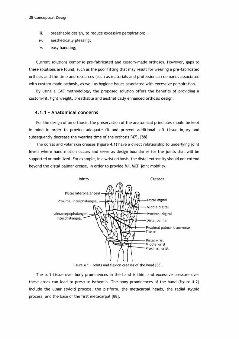
38 Conceptual Design
iii. breathable design, to reduce excessive perspiration;
iv. aesthetically pleasing;
v. easy handling;
Current solutions comprise pre-fabricated and custom-made orthoses. However, gaps to
these solutions are found, such as the poor fitting that may result for wearing a pre-fabricated
orthosis and the time and resources (such as materials and professionals) demands associated
with custom-made orthosis, as well as hygiene issues associated with excessive perspiration.
By using a CAE methodology, the proposed solution offers the benefits of providing a
custom-fit, light weight, breathable and aesthetically enhanced orthosis design.
4.1.1 - Anatomical concerns
For the design of an orthosis, the preservation of the anatomical principles should be kept
in mind in order to provide adequate fit and prevent additional soft tissue injury and
subsequently decrease the wearing time of the orthosis [47], [88].
The dorsal and volar skin creases (figure 4.1) have a direct relationship to underlying joint
levels where hand motion occurs and serve as design boundaries for the joints that will be
supported or mobilized. For example, in a wrist orthosis, the distal extremity should not extend
beyond the distal palmar crease, in order to provide full MCP joint mobility.
Figure 4.1 – Joints and flexion creases of the hand [88].
The soft tissue over bony prominences in the hand is thin, and excessive pressure over
these areas can lead to pressure ischemia. The bony prominences of the hand (figure 4.2)
include the ulnar styloid process, the pisiform, the metacarpal heads, the radial styloid
process, and the base of the first metacarpal [88].

Concept generation 39
Figure 4.2 – Dorsal and volar views of the bony prominences of the hand [88].
Other concerns imply the preservation of the palmar arches, keeping an anti-deformity
position and guaranteeing that the fixing methods (for example straps) allow a correct blood
flow [47].
4.1.2 - Mechanical principles
The wear of an orthosis results in the application of external forces to the upper limb.
Therefore, when designing orthoses, a basic understanding of the biomechanical principles
involved in the design, construction and fitting of such orthoses is necessary [1].
Generally, splints function as a first-class lever systems with three points of pressure acting
upon the extremity. Figure 4.3 shows a simple wrist orthosis positioning, where the wrist in a
neutral position locates the three points of pressure. The first point of pressure in the orthosis
occurs at the wrist, the axis of the joint. The other points of pressure occur at the forearm
(proximal end) and the palmar aspect (distal end) of the orthosis. The forearm support serves
as the force arm, and the palmar aspect acts as the resistance arm to the weight of the hand.
The proximal and distal ends of the orthosis act as the counterforce against the opposing middle
force applied by the material placed dorsally on the wrist (for example, straps) [88].
Figure 4.3 – First class lever example on a wrist neutral immobilization splint. A represents the axis at the wrist, R the hand weight or resistance and F the counterforce provided by the forearm [1].
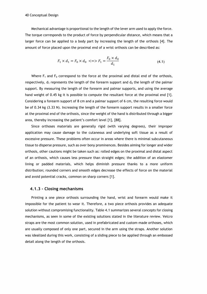
40 Conceptual Design
Mechanical advantage is proportional to the length of the lever arm used to apply the force.
The torque corresponds to the product of force by perpendicular distance, which means that a
larger force can be applied to a body part by increasing the length of the orthosis [4]. The
amount of force placed upon the proximal end of a wrist orthosis can be described as:
𝐹1 × 𝑑1 = 𝐹0 × 𝑑0 <=> 𝐹1 =𝐹0 × 𝑑0
𝑑1
Where F1 and F0 correspond to the force at the proximal and distal end of the orthosis,
respectively, d1 represents the length of the forearm support and d0 the length of the palmar
support. By measuring the length of the forearm and palmar supports, and using the average
hand weight of 0.45 kg it is possible to compute the resultant force at the proximal end [1].
Considering a forearm support of 8 cm and a palmar support of 6 cm, the resulting force would
be of 0.34 kg (3.33 N). Increasing the length of the forearm support results in a smaller force
at the proximal end of the orthosis, since the weight of the hand is distributed through a bigger
area, thereby increasing the patient’s comfort level [1], [88].
Since orthoses materials are generally rigid (with varying degrees), their improper
application may cause damage to the cutaneous and underlying soft tissue as a result of
excessive pressure. These problems often occur in areas where there is minimal subcutaneous
tissue to disperse pressure, such as over bony prominences. Besides aiming for longer and wider
orthosis, other cautions might be taken such as: rolled edges on the proximal and distal aspect
of an orthosis, which causes less pressure than straight edges; the addition of an elastomer
lining or padded materials, which helps diminish pressure thanks to a more uniform
distribution; rounded corners and smooth edges decrease the effects of force on the material
and avoid potential cracks, common on sharp corners [1].
4.1.3 - Closing mechanisms
Printing a one piece orthosis surrounding the hand, wrist and forearm would make it
impossible for the patient to wear it. Therefore, a two piece orthosis provides an adequate
solution without compromising functionality. Table 4.1 summarizes several concepts for closing
mechanisms, as seen in some of the existing solutions stated in the literature review. Velcro
straps are the most common solution, used in prefabricated and custom-made orthoses, which
are usually composed of only one part, secured in the arm using the straps. Another solution
was idealized during this work, consisting of a sliding piece to be applied through an embossed
detail along the length of the orthosis.
(4.1)
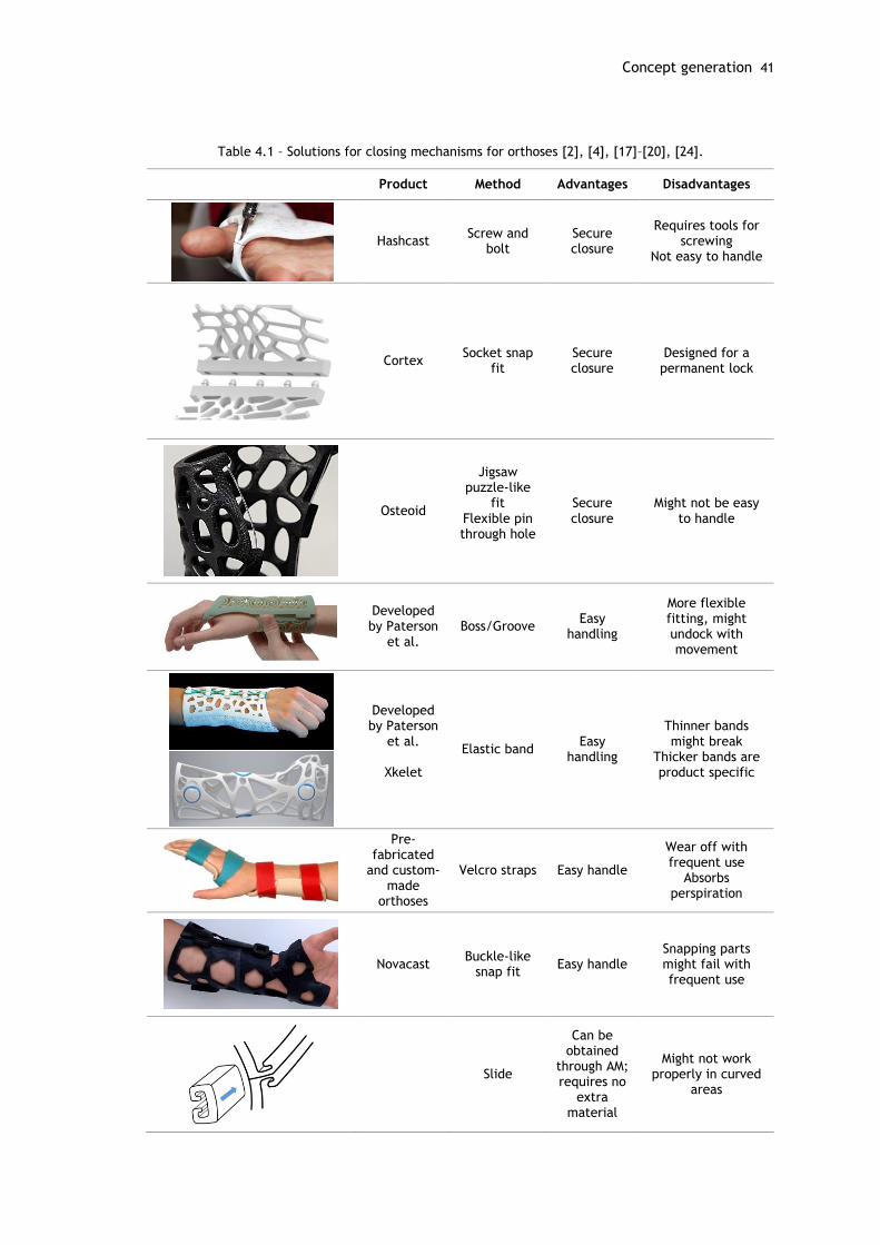
Concept generation 41
Table 4.1 – Solutions for closing mechanisms for orthoses [2], [4], [17]–[20], [24].
Product Method Advantages Disadvantages
Hashcast Screw and
bolt Secure closure
Requires tools for screwing
Not easy to handle
Cortex Socket snap
fit Secure closure
Designed for a permanent lock
Osteoid
Jigsaw puzzle-like
fit Flexible pin through hole
Secure closure
Might not be easy to handle
Developed by Paterson
et al. Boss/Groove
Easy handling
More flexible fitting, might undock with movement
Developed by Paterson
et al.
Xkelet
Elastic band Easy
handling
Thinner bands might break
Thicker bands are product specific
Pre-fabricated
and custom-made
orthoses
Velcro straps Easy handle
Wear off with frequent use
Absorbs perspiration
Novacast Buckle-like
snap fit Easy handle
Snapping parts might fail with frequent use
Slide
Can be obtained
through AM; requires no
extra material
Might not work properly in curved
areas
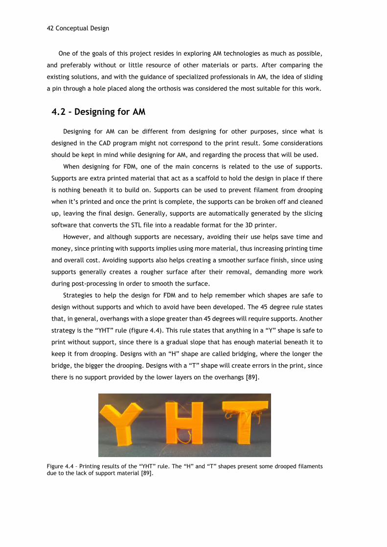
42 Conceptual Design
One of the goals of this project resides in exploring AM technologies as much as possible,
and preferably without or little resource of other materials or parts. After comparing the
existing solutions, and with the guidance of specialized professionals in AM, the idea of sliding
a pin through a hole placed along the orthosis was considered the most suitable for this work.
4.2 - Designing for AM
Designing for AM can be different from designing for other purposes, since what is
designed in the CAD program might not correspond to the print result. Some considerations
should be kept in mind while designing for AM, and regarding the process that will be used.
When designing for FDM, one of the main concerns is related to the use of supports.
Supports are extra printed material that act as a scaffold to hold the design in place if there
is nothing beneath it to build on. Supports can be used to prevent filament from drooping
when it’s printed and once the print is complete, the supports can be broken off and cleaned
up, leaving the final design. Generally, supports are automatically generated by the slicing
software that converts the STL file into a readable format for the 3D printer.
However, and although supports are necessary, avoiding their use helps save time and
money, since printing with supports implies using more material, thus increasing printing time
and overall cost. Avoiding supports also helps creating a smoother surface finish, since using
supports generally creates a rougher surface after their removal, demanding more work
during post-processing in order to smooth the surface.
Strategies to help the design for FDM and to help remember which shapes are safe to
design without supports and which to avoid have been developed. The 45 degree rule states
that, in general, overhangs with a slope greater than 45 degrees will require supports. Another
strategy is the “YHT” rule (figure 4.4). This rule states that anything in a “Y” shape is safe to
print without support, since there is a gradual slope that has enough material beneath it to
keep it from drooping. Designs with an “H” shape are called bridging, where the longer the
bridge, the bigger the drooping. Designs with a “T” shape will create errors in the print, since
there is no support provided by the lower layers on the overhangs [89].
Figure 4.4 – Printing results of the “YHT” rule. The “H” and “T” shapes present some drooped filaments due to the lack of support material [89].
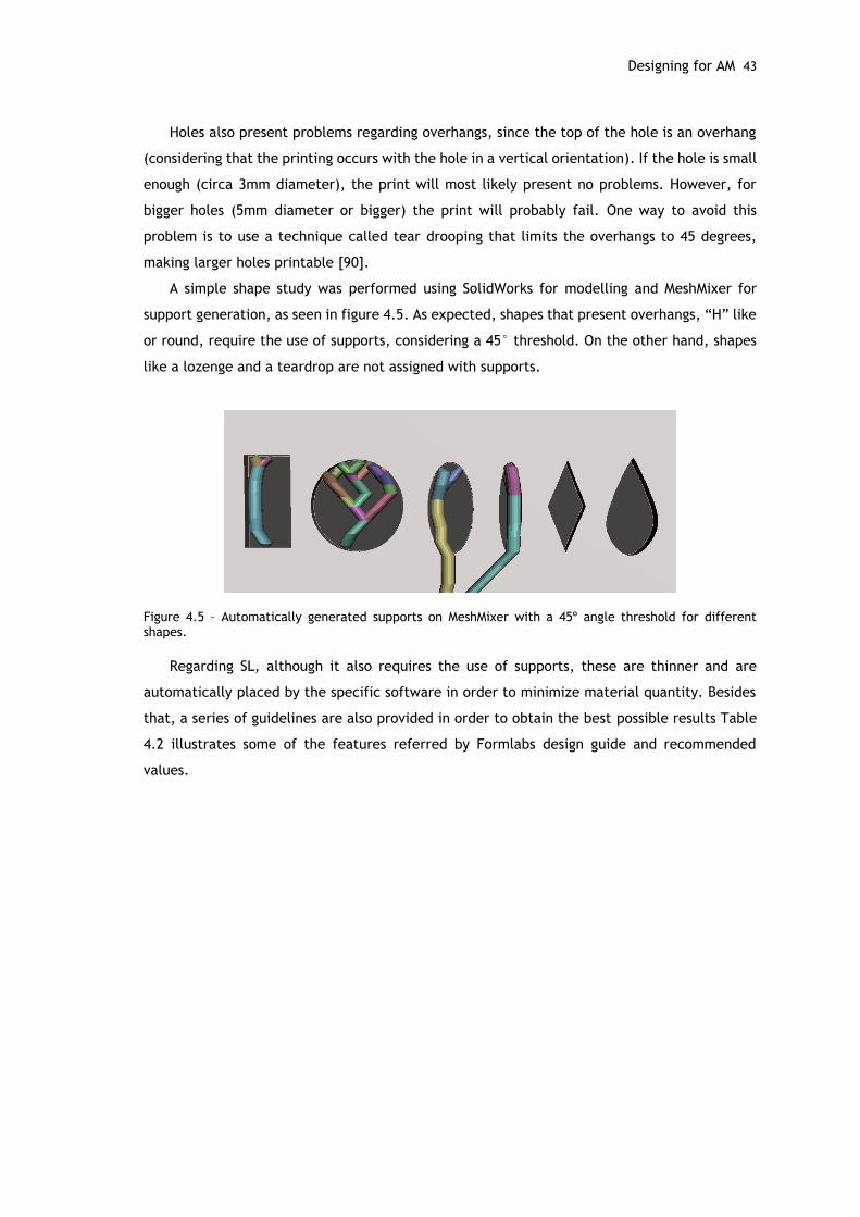
Designing for AM 43
Holes also present problems regarding overhangs, since the top of the hole is an overhang
(considering that the printing occurs with the hole in a vertical orientation). If the hole is small
enough (circa 3mm diameter), the print will most likely present no problems. However, for
bigger holes (5mm diameter or bigger) the print will probably fail. One way to avoid this
problem is to use a technique called tear drooping that limits the overhangs to 45 degrees,
making larger holes printable [90].
A simple shape study was performed using SolidWorks for modelling and MeshMixer for
support generation, as seen in figure 4.5. As expected, shapes that present overhangs, “H” like
or round, require the use of supports, considering a 45° threshold. On the other hand, shapes
like a lozenge and a teardrop are not assigned with supports.
Figure 4.5 – Automatically generated supports on MeshMixer with a 45º angle threshold for different shapes.
Regarding SL, although it also requires the use of supports, these are thinner and are
automatically placed by the specific software in order to minimize material quantity. Besides
that, a series of guidelines are also provided in order to obtain the best possible results Table
4.2 illustrates some of the features referred by Formlabs design guide and recommended
values.
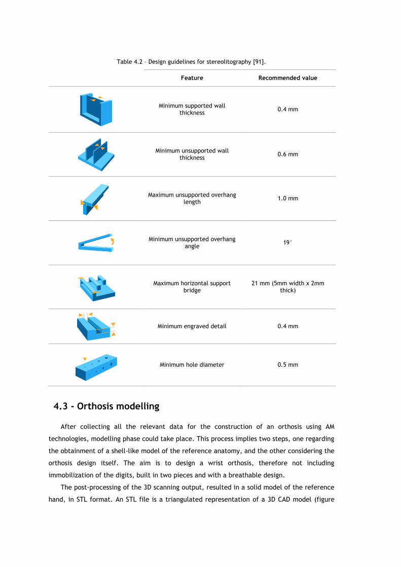
Table 4.2 – Design guidelines for stereolitography [91].
Feature Recommended value
Minimum supported wall thickness
0.4 mm
Minimum unsupported wall thickness
0.6 mm
Maximum unsupported overhang length
1.0 mm
Minimum unsupported overhang angle
19°
Maximum horizontal support bridge
21 mm (5mm width x 2mm thick)
Minimum engraved detail 0.4 mm
Minimum hole diameter 0.5 mm
4.3 - Orthosis modelling
After collecting all the relevant data for the construction of an orthosis using AM
technologies, modelling phase could take place. This process implies two steps, one regarding
the obtainment of a shell-like model of the reference anatomy, and the other considering the
orthosis design itself. The aim is to design a wrist orthosis, therefore not including
immobilization of the digits, built in two pieces and with a breathable design.
The post-processing of the 3D scanning output, resulted in a solid model of the reference
hand, in STL format. An STL file is a triangulated representation of a 3D CAD model (figure
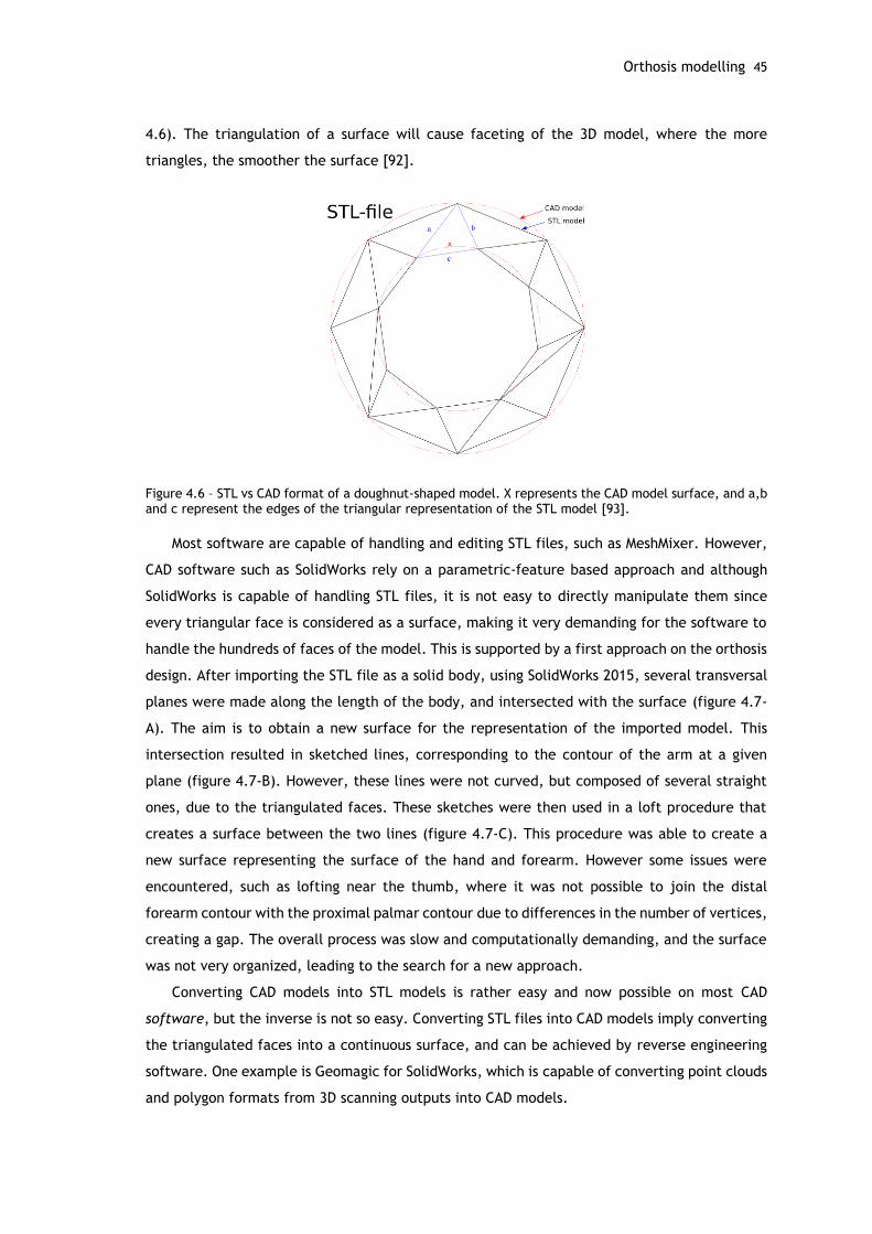
Orthosis modelling 45
4.6). The triangulation of a surface will cause faceting of the 3D model, where the more
triangles, the smoother the surface [92].
Figure 4.6 – STL vs CAD format of a doughnut-shaped model. X represents the CAD model surface, and a,b and c represent the edges of the triangular representation of the STL model [93].
Most software are capable of handling and editing STL files, such as MeshMixer. However,
CAD software such as SolidWorks rely on a parametric-feature based approach and although
SolidWorks is capable of handling STL files, it is not easy to directly manipulate them since
every triangular face is considered as a surface, making it very demanding for the software to
handle the hundreds of faces of the model. This is supported by a first approach on the orthosis
design. After importing the STL file as a solid body, using SolidWorks 2015, several transversal
planes were made along the length of the body, and intersected with the surface (figure 4.7-
A). The aim is to obtain a new surface for the representation of the imported model. This
intersection resulted in sketched lines, corresponding to the contour of the arm at a given
plane (figure 4.7-B). However, these lines were not curved, but composed of several straight
ones, due to the triangulated faces. These sketches were then used in a loft procedure that
creates a surface between the two lines (figure 4.7-C). This procedure was able to create a
new surface representing the surface of the hand and forearm. However some issues were
encountered, such as lofting near the thumb, where it was not possible to join the distal
forearm contour with the proximal palmar contour due to differences in the number of vertices,
creating a gap. The overall process was slow and computationally demanding, and the surface
was not very organized, leading to the search for a new approach.
Converting CAD models into STL models is rather easy and now possible on most CAD
software, but the inverse is not so easy. Converting STL files into CAD models imply converting
the triangulated faces into a continuous surface, and can be achieved by reverse engineering
software. One example is Geomagic for SolidWorks, which is capable of converting point clouds
and polygon formats from 3D scanning outputs into CAD models.
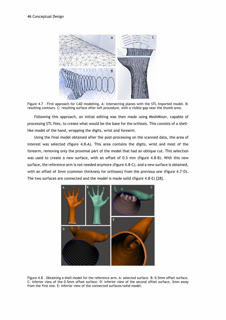
46 Conceptual Design
Figure 4.7 – First approach for CAD modelling. A: intersecting planes with the STL imported model. B: resulting contours. C: resulting surface after loft procedure, with a visible gap near the thumb area.
Following this approach, an initial editing was then made using MeshMixer, capable of
processing STL files, to create what would be the base for the orthosis. This consists of a shell-
like model of the hand, wrapping the digits, wrist and forearm.
Using the final model obtained after the post-processing on the scanned data, the area of
interest was selected (figure 4.8-A). This area contains the digits, wrist and most of the
forearm, removing only the proximal part of the model that had an oblique cut. This selection
was used to create a new surface, with an offset of 0.5 mm (figure 4.8-B). With this new
surface, the reference arm is not needed anymore (figure 4.8-C), and a new surface is obtained,
with an offset of 3mm (common thickness for orthoses) from the previous one (figure 4.7-D).
The two surfaces are connected and the model is made solid (figure 4.8-E) [28].
Figure 4.8 – Obtaining a shell model for the reference arm. A: selected surface. B: 0.5mm offset surface. C: inferior view of the 0.5mm offset surface. D: inferior view of the second offset surface, 3mm away from the first one. E: inferior view of the connected surfaces/solid model.
A
B
C

Orthosis modelling 47
The shell model of the reference arm is exported as an STL file. Using Geomagics for
SolidWorks, the model is converted into a CAD model, for further editing. For that, the
autosurface tool was used, set to an organic type object. The file is converted into a CAD
surface, as seen in figure 4.9, and the repair and smooth tools are used in order to correct
minor issues and improve the quality of the surface.
Figure 4.9 – CAD model obtained through the conversion of the STL file using Geomagic for SolidWorks.
The resulting CAD model is much more satisfactory than the one obtained in the first
approach, and is used for further editing using SolidWorks.
The next step implies editing the model in order to fulfill the shape specifications of a wrist
orthosis. This implies the removal of material in the digits, guaranteeing their full motion by
considering the distal palmar crease. The bony prominence of the base of the first metacarpal
is also taken into account when removing the material.
For that, a new plane is created and placed longitudinally in the middle of the arm, and
three splines are sketched. These splines, as seen in figure 4.10-A, will serve as guidelines for
the splitting of the shell and are placed distally (below the distal crease), laterally (freeing the
thumb) and proximally. Although it is preferable to have a longer forearm support for an
orthosis, due to printing size restrictions, the design was chosen to have a smaller length for
the forearm part. Using the sketched splines, the split line command was used in order to
project the lines into the surface of the shell model. These splines were then used to split the
body, resulting in 4 solid bodies, were the ones that were no longer needed were suppressed
(figure 4.10-B).
Figure 4.10 – Obtaining the shape of a wrist orthosis. A: reference lines for splitting the shell. B: resulting body after splitting.
A B

48 Conceptual Design
More split lines were added 10 mm away from the edges, in order to set a border were
little or no mass should be removed, guaranteeing a more structurally viable design. These
borders were painted red for visual aid purposes (figure 4.11-B,C).
The holes for the pin to be inserted were generated by creating a path line along the model.
For that, a section view at the middle plane helped the drawing of a line using the spline on
surface tool along the borders. The point where this line intersected with the proximal edge
of the model was used to create a coincident plane to the proximal edge, were a circle of 1.3
mm was sketched in order to create a profile for the hole (figure 4.11-A). The pin to fix the
orthosis is intended to be a 1.1 mm wire, therefore the hole was recommended to be drawn
with a slight margin, in this case of 0.2 mm, to guarantee a correct fit after printing. With the
path and the profile created, a swept cut was performed, creating two holes in the model
(figure 4.11-B). The distal extremities of the holes were rounded using a 0.6 mm radius fillet.
In order to split the body in two, a sketch was added into a new vertical plane, placed at
the right side of the model. A 20 mm border was considered along the length of the model, and
a centerline was sketched in between. A puzzle-like pattern was created, with a height of 10
mm and length of 20mm per prominence, 5mm away from each border (figure 4.11-C). The
sides of the prominences were tilted by 95°in order to difficult vertical sliding of the parts. A
new surface was extruded from this sketch (figure 4.11-D) and used as reference to split the
body using the split tool. This creates two bodies, separated lengthwise, along the lateral and
medial side of the arm, and between the thumb and fingers.
Figure 4.11 – Designing a two part orthosis model. A: sketched path and profile for the hole on a section view of the model. B: outline of the resulting holes along the model. C: sketch and respective dimensions used for splitting the body. D: resulting extruded surface, used to split the body in two.
To design the fit for the part between the fingers, a simple boss and groove approach were
designed. This required working in the two separate parts. The groove was placed in the bottom
part, and the boss on the top part. A new plane was created, coincident to the area where the
split was performed. In this plane, a diagonal centerline was sketched, joining the interior
A B
C D

Orthosis modelling 49
distal corner and the exterior proximal corner, in order to guarantee repeatability of the
process on the other part. A center point for this line was obtained, and a 6 mm centerline was
sketched, forming an angle of 23° with the diagonal line (figure 4.12-A). From this line, an
ellipse was obtained, with a 0.7 mm radius. This ellipse was used to perform an extruded cut
with a depth of 2mm. The edges were rounded using a 0.6mm fillet on the interior edge, and
a 0.5 mm fillet on the exterior one (figure 4.12-B). A similar procedure was performed in the
top part, except that instead of an extruded cut, an extruded boss was obtained in order to fit
the groove, as seen in figures 4.12-C,D. The two parts are assembled together with the
reference arm, in order to check the fitting of the design (figure 4.13).
Figure 4.12 – Fitting part details. A: sketch on cut surface for and elliptical groove/boss. B: resulting groove in bottom part. C: resulting boss on top part. D: Detail of the fitting of the boss into the groove; fitting of the puzzle-like protuberances is also visible.
Figure 4.13 – Rendered images of the orthosis model. A, B: Positioning the top and bottom parts on the arm. C, D: Assembled parts and fitting on the arm.
With the validated model, and in order to remove mass and facilitate ventilation, further
editing was performed. MeshMixer provides a tool that is capable of creating lattice-like
shapes, or more commonly called Voronoi patterns. The result of the application of this tool is
A B
C D
A B
C D

50 Conceptual Design
visible in figure 4.14, and is similar to some of the existing solutions discussed in the literature
review.
Figure 4.14 – Result of the applied Voronoi pattern on the reference arm surface, using MeshMixer.
Although aesthetically interesting, this structure will most probably ask for a large number
of supports and does not consider the bony prominences. Therefore, a different approach was
followed for material removal, and two shapes were considered, the lozenge and the tear,
since these were the shapes that required no supports in the previously made support test
(figure 4.5). These shapes are used in order to create “material removal cells” in the model.
The top and bottom parts were edited separately and with the same procedure. A new
plane is created just above the top part and below the bottom part. In this plane, the selected
shapes are sketched following four approaches. In the first one, tear-like shapes (maximum
height of 30 mm) were chosen as the material removal shape. The shapes were designed using
splines, and manually distributed. This model is 38.17% lighter than the first model. A second
approach evolved from the first one, but with more narrow, almond-like shapes (30.29%
lighter). To explore other shapes, a regular pattern of lozenge cells (25mm height and 10 mm
width) using the sketch pattern tool was created (29.23% lighter). An enhancement of this third
model is explored through a more careful distribution and configuration of the cells. The
lozenges are manipulated in size and position in order to better fill the space and increase
material removal (31.63% lighter). The bony prominences were taken into consideration and
material was removed on the head of the ulna and pisiform bone areas. In order to manually
disposition the sketched shapes, the operations of move, scale and rotate were applied.
The shapes are then projected into the model surface for the extruded cut. The lateral
areas of the model are not parallel to the plane, therefore performing the extruded cut in the
same perpendicular direction would result in cuts with tilted edges on the lateral areas of the
model. To avoid this, the extruded cut is made according to three directions, so that the
resulting hole is perpendicular to the surface. To achieve this, the sketch is separated in three
different parts (left, center and right) and each one includes the cells that correspond to that
area. Figure 4.15-A shows the sketch of the tear shape in the top part, where it is possible to
distinguish the middle sketch, represented with a solid line, and the left and right sketches
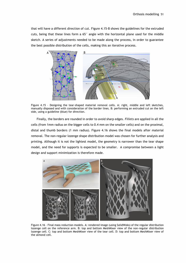
Orthosis modelling 51
that will have a different direction of cut. Figure 4.15-B shows the guidelines for the extruded
cuts, being that these lines form a 65° angle with the horizontal plane used for the middle
sketch. A series of adjustments needed to be made along the process, in order to guarantee
the best possible distribution of the cells, making this an iterative process.
Figure 4.15 – Designing the tear-shaped material removal cells. A: right, middle and left sketches, manually disposed and with consideration of the border lines. B: performing an extruded cut on the left side, using a guideline (blue) for direction.
Finally, the borders are rounded in order to avoid sharp edges. Fillets are applied in all the
cells (from 1mm radius on the bigger cells to 0.4 mm on the smaller cells) and on the proximal,
distal and thumb borders (1 mm radius). Figure 4.16 shows the final models after material
removal. The non-regular lozenge shape distribution model was chosen for further analysis and
printing. Although it is not the lightest model, the geometry is narrower than the tear shape
model, and the need for supports is expected to be smaller. A compromise between a light
design and support minimization is therefore made.
Figure 4.16 – Final mass reduction models. A: rendered image (using SolidWoks) of the regular distribution lozenge cell on the reference arm. B: top and bottom MeshMixer view of the non-regular distribution lozenge cell. C: top and bottom MeshMixer view of the tear cell. D: top and bottom MeshMixer view of the almond cell.
A B
A B
C D
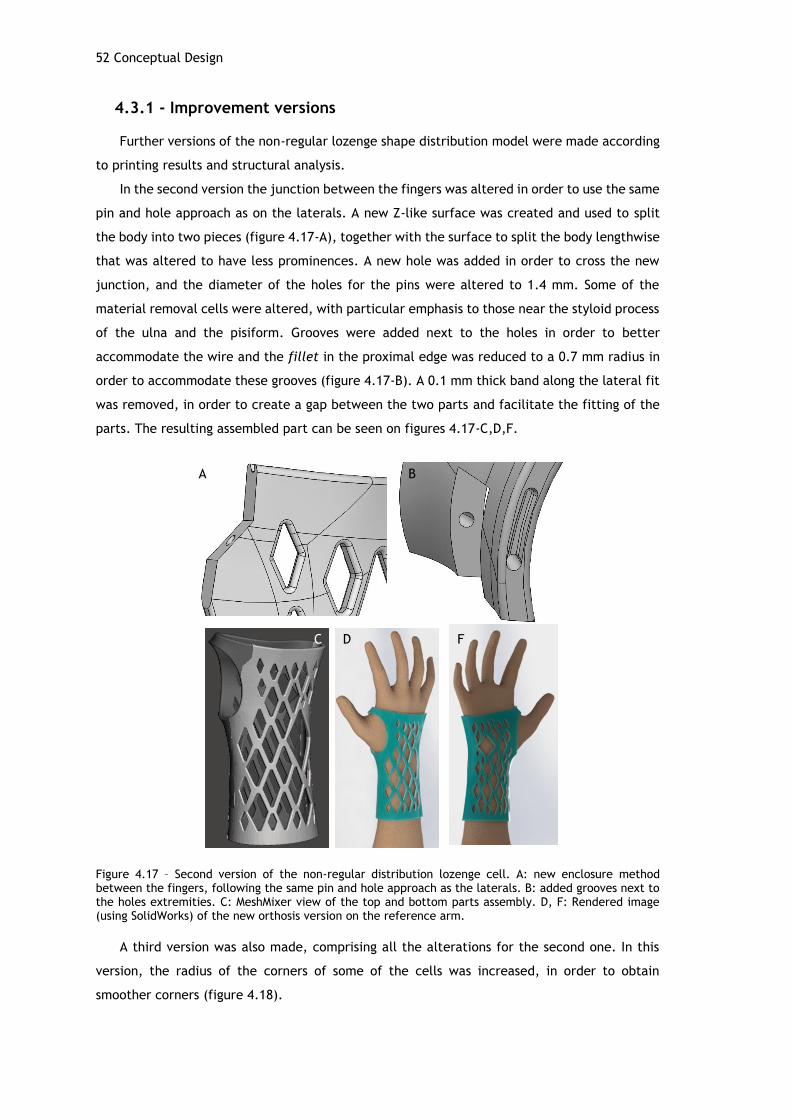
52 Conceptual Design
4.3.1 - Improvement versions
Further versions of the non-regular lozenge shape distribution model were made according
to printing results and structural analysis.
In the second version the junction between the fingers was altered in order to use the same
pin and hole approach as on the laterals. A new Z-like surface was created and used to split
the body into two pieces (figure 4.17-A), together with the surface to split the body lengthwise
that was altered to have less prominences. A new hole was added in order to cross the new
junction, and the diameter of the holes for the pins were altered to 1.4 mm. Some of the
material removal cells were altered, with particular emphasis to those near the styloid process
of the ulna and the pisiform. Grooves were added next to the holes in order to better
accommodate the wire and the fillet in the proximal edge was reduced to a 0.7 mm radius in
order to accommodate these grooves (figure 4.17-B). A 0.1 mm thick band along the lateral fit
was removed, in order to create a gap between the two parts and facilitate the fitting of the
parts. The resulting assembled part can be seen on figures 4.17-C,D,F.
Figure 4.17 – Second version of the non-regular distribution lozenge cell. A: new enclosure method between the fingers, following the same pin and hole approach as the laterals. B: added grooves next to the holes extremities. C: MeshMixer view of the top and bottom parts assembly. D, F: Rendered image (using SolidWorks) of the new orthosis version on the reference arm.
A third version was also made, comprising all the alterations for the second one. In this
version, the radius of the corners of some of the cells was increased, in order to obtain
smoother corners (figure 4.18).
A B
C D F
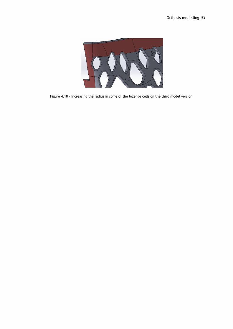
Orthosis modelling 53
Figure 4.18 – Increasing the radius in some of the lozenge cells on the third model version.

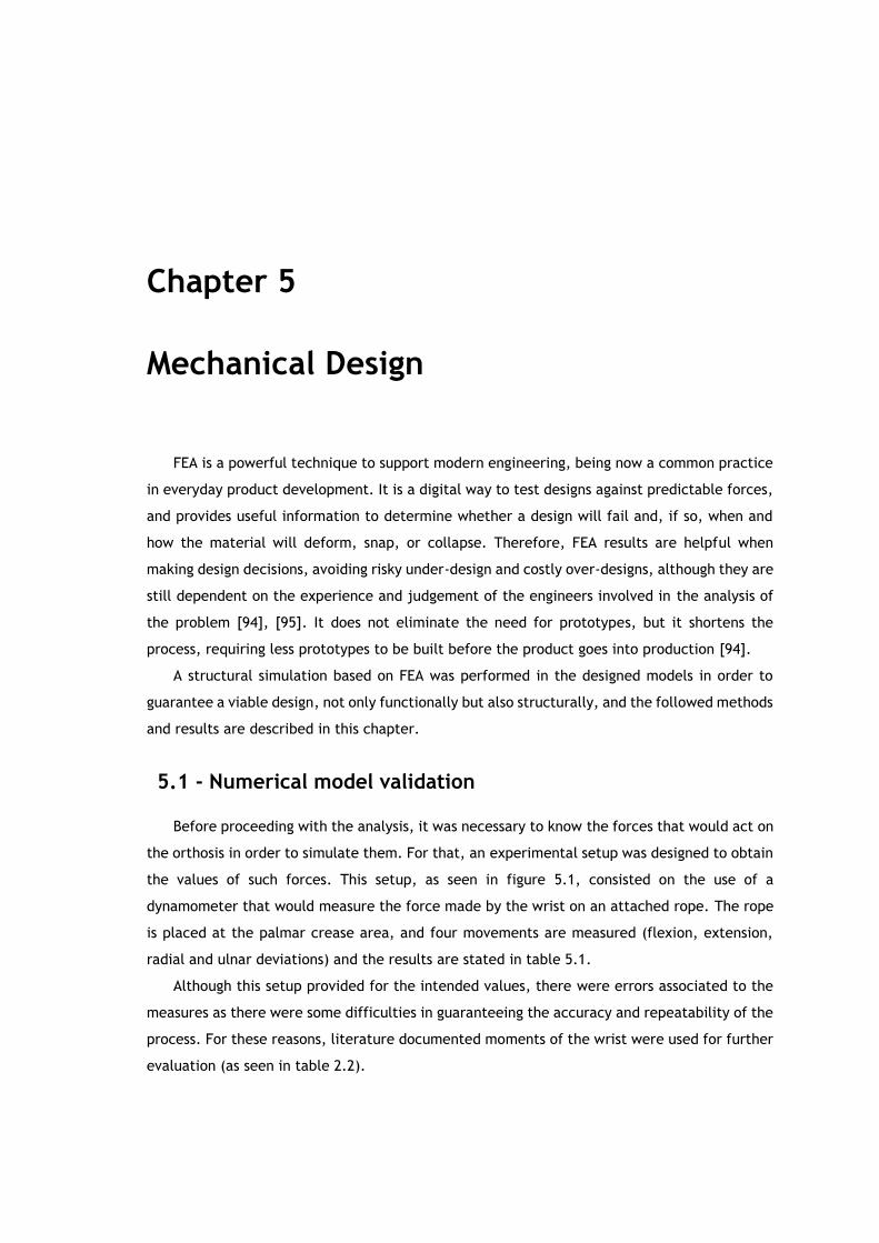
Chapter 5
Mechanical Design
FEA is a powerful technique to support modern engineering, being now a common practice
in everyday product development. It is a digital way to test designs against predictable forces,
and provides useful information to determine whether a design will fail and, if so, when and
how the material will deform, snap, or collapse. Therefore, FEA results are helpful when
making design decisions, avoiding risky under-design and costly over-designs, although they are
still dependent on the experience and judgement of the engineers involved in the analysis of
the problem [94], [95]. It does not eliminate the need for prototypes, but it shortens the
process, requiring less prototypes to be built before the product goes into production [94].
A structural simulation based on FEA was performed in the designed models in order to
guarantee a viable design, not only functionally but also structurally, and the followed methods
and results are described in this chapter.
5.1 - Numerical model validation
Before proceeding with the analysis, it was necessary to know the forces that would act on
the orthosis in order to simulate them. For that, an experimental setup was designed to obtain
the values of such forces. This setup, as seen in figure 5.1, consisted on the use of a
dynamometer that would measure the force made by the wrist on an attached rope. The rope
is placed at the palmar crease area, and four movements are measured (flexion, extension,
radial and ulnar deviations) and the results are stated in table 5.1.
Although this setup provided for the intended values, there were errors associated to the
measures as there were some difficulties in guaranteeing the accuracy and repeatability of the
process. For these reasons, literature documented moments of the wrist were used for further
evaluation (as seen in table 2.2).

56 Mechanical Design
Figure 5.1 – Setup for wrist force measurement using a dynamometer.
Table 5.1 – Maximum forces measured by the dynamometer.
Movement Maximum force (N)
Flexion 30
Extension 25
Radial deviation 30
Ulnar deviation 30
The software used for simulation was SolidWorks, which is becoming a powerful and more
common tool regarding FEA, as it is more user friendly and allows for a direct editing of the
model in case of need. This helps to speed up the process, since the modelling was also made
using SolidWorks. However, other powerful FEA software are also commonly used, such as
ANSYS or Abaqus. For this reason a trial simulation was performed in order to compare the
results of two software (SolidWorks and ANSYS) and validate the results provided by SolidWorks.
For that, the model was simplified for simulation purposes: considered as one body only
(and eliminating the holes) and fillets were removed, since they increase the complexity of
the model and therefore of the mesh. Simple boundary conditions were applied, a 30N
downward force on the distal edge of the orthosis (based on the results of the trial force
measurements), and a restriction on the proximal edge, considered as fixed (figure 5.2).
Figure 5.2 – Free body diagram of the trial simulation. F represents the applied force of 30N. The green edge represents the fixed restriction of the proximal edge.
F

Numerical model validation 57
The simulation was performed as a static analysis, using SolidWorks and ANSYS. Static
studies are time-invariant and suitable to calculate stresses, displacements and reaction
forces, and are used when material properties are linear [96]. Due to ANSYS licensing
restrictions (maximum 32000 nodes/elements), the element size of the mesh was of 4mm, and
at the faces of the distal and thumb edges a mesh control was applied to generate 1mm
elements to guarantee more than one element in thickness. SolidWorks generated mesh has
36404 nodes and 18704 elements and ANSYS generated mesh 31556 nodes and 16140 elements
(tetrahedral elements were used in both cases). The same conditions were applied in
SolidWorks simulator. The simulation results for this case study are visible in figure 5.3.
Figure 5.3 –Equivalent von Mises stress distribution for the performed simulation (normalized from 0 to 4.628 MPa). A: SolidWorks results. B: ANSYS results.
Results show that the maximum von Mises stress is very similar in both cases, being 4.628
MPa in SolidWorks Simulation and 4.474 MPa in ANSYS simulation. Both simulations show the
same stress distribution. SolidWorks is therefore considered as a viable option and used for
further simulations.
As stated previously, using literature values for wrist moments was considered as a more
accurate approach, better representing the real movements of the wrist. A new set of
simulations were performed, now considering different boundary conditions. The same model
simplifications were performed, i.e., considering the model as one body only and eliminating
A
B
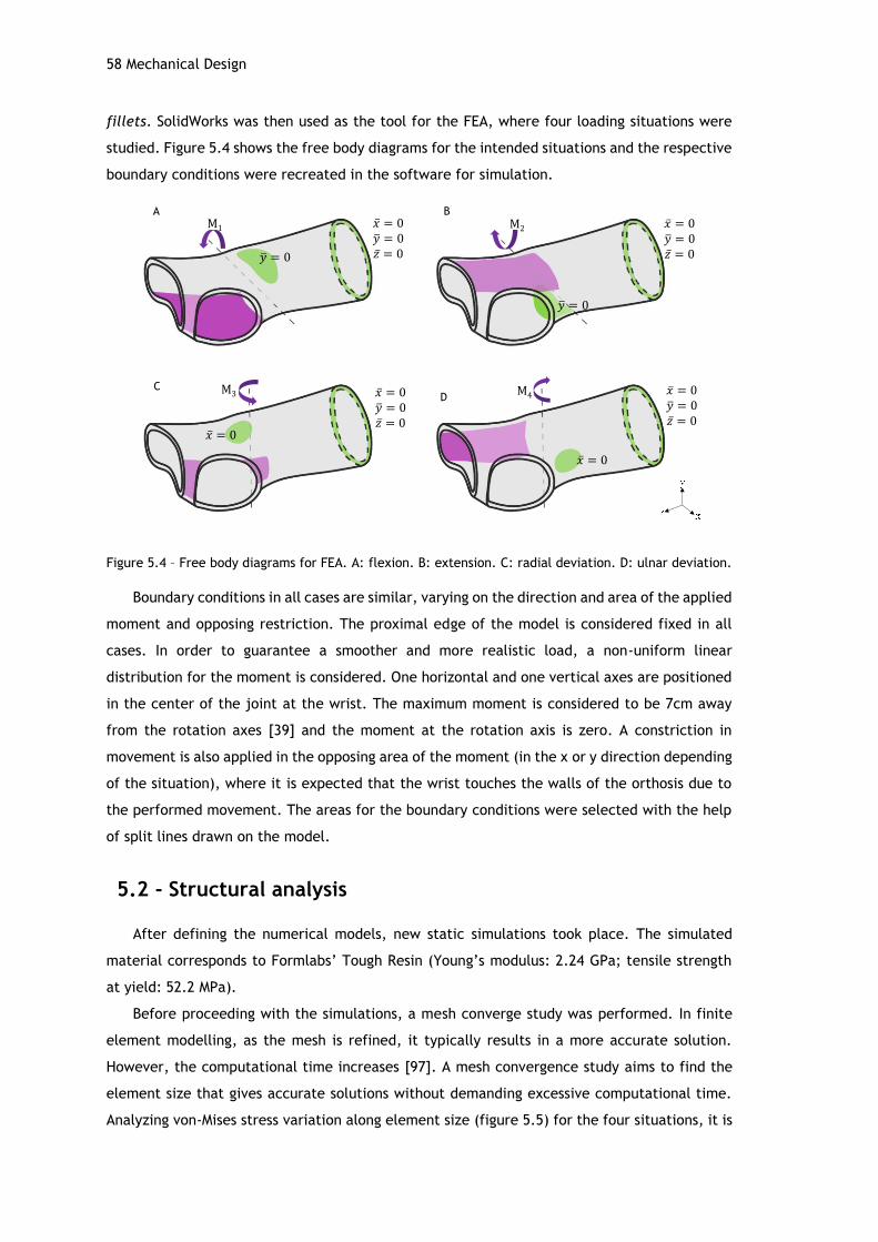
58 Mechanical Design
fillets. SolidWorks was then used as the tool for the FEA, where four loading situations were
studied. Figure 5.4 shows the free body diagrams for the intended situations and the respective
boundary conditions were recreated in the software for simulation.
Figure 5.4 – Free body diagrams for FEA. A: flexion. B: extension. C: radial deviation. D: ulnar deviation.
Boundary conditions in all cases are similar, varying on the direction and area of the applied
moment and opposing restriction. The proximal edge of the model is considered fixed in all
cases. In order to guarantee a smoother and more realistic load, a non-uniform linear
distribution for the moment is considered. One horizontal and one vertical axes are positioned
in the center of the joint at the wrist. The maximum moment is considered to be 7cm away
from the rotation axes [39] and the moment at the rotation axis is zero. A constriction in
movement is also applied in the opposing area of the moment (in the x or y direction depending
of the situation), where it is expected that the wrist touches the walls of the orthosis due to
the performed movement. The areas for the boundary conditions were selected with the help
of split lines drawn on the model.
5.2 - Structural analysis
After defining the numerical models, new static simulations took place. The simulated
material corresponds to Formlabs’ Tough Resin (Young’s modulus: 2.24 GPa; tensile strength
at yield: 52.2 MPa).
Before proceeding with the simulations, a mesh converge study was performed. In finite
element modelling, as the mesh is refined, it typically results in a more accurate solution.
However, the computational time increases [97]. A mesh convergence study aims to find the
element size that gives accurate solutions without demanding excessive computational time.
Analyzing von-Mises stress variation along element size (figure 5.5) for the four situations, it is
M1 M2
M3 M4
A B
CD
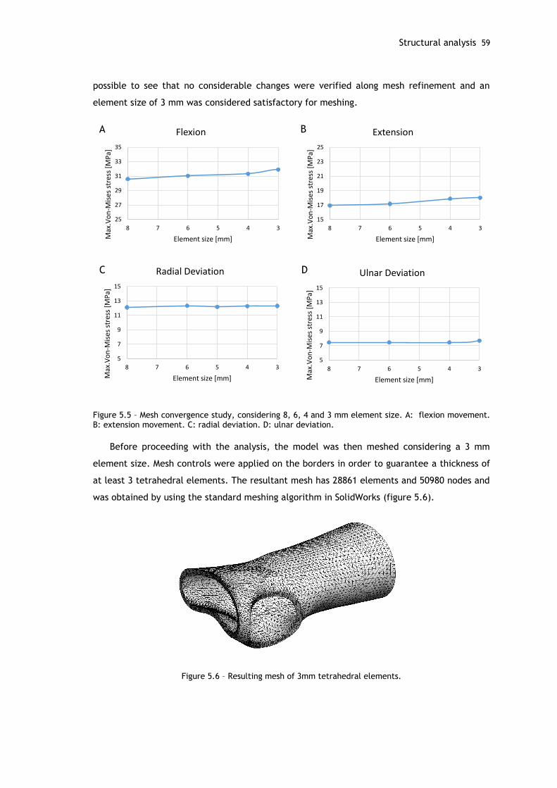
Structural analysis 59
possible to see that no considerable changes were verified along mesh refinement and an
element size of 3 mm was considered satisfactory for meshing.
Figure 5.5 – Mesh convergence study, considering 8, 6, 4 and 3 mm element size. A: flexion movement. B: extension movement. C: radial deviation. D: ulnar deviation.
Before proceeding with the analysis, the model was then meshed considering a 3 mm
element size. Mesh controls were applied on the borders in order to guarantee a thickness of
at least 3 tetrahedral elements. The resultant mesh has 28861 elements and 50980 nodes and
was obtained by using the standard meshing algorithm in SolidWorks (figure 5.6).
Figure 5.6 – Resulting mesh of 3mm tetrahedral elements.
25
27
29
31
33
35
345678
Max
.Vo
n-M
ises
str
ess
[MP
a]
Element size [mm]
Flexion
15
17
19
21
23
25
345678
Max
.Vo
n-M
ises
str
ess
[MP
a]
Element size [mm]
Extension
5
7
9
11
13
15
345678
Max
.Vo
n-M
ises
str
ess
[MP
a]
Element size [mm]
Ulnar Deviation
5
7
9
11
13
15
345678
Max
.Vo
n-M
ises
str
ess
[MP
a]
Element size [mm]
Radial Deviation
A B
C D
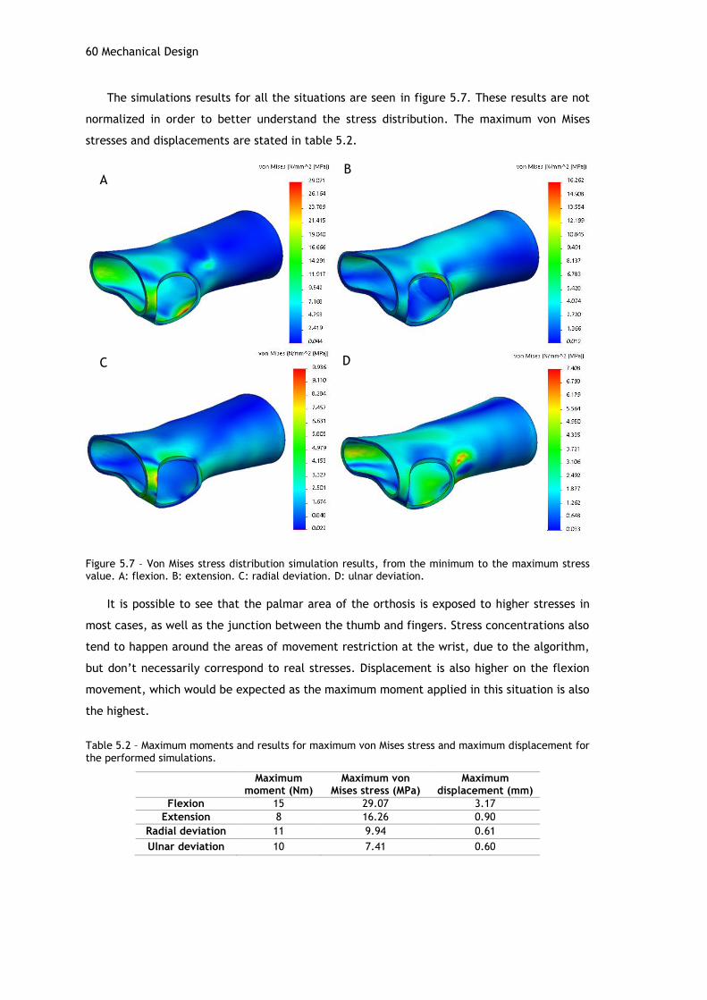
60 Mechanical Design
The simulations results for all the situations are seen in figure 5.7. These results are not
normalized in order to better understand the stress distribution. The maximum von Mises
stresses and displacements are stated in table 5.2.
Figure 5.7 – Von Mises stress distribution simulation results, from the minimum to the maximum stress value. A: flexion. B: extension. C: radial deviation. D: ulnar deviation.
It is possible to see that the palmar area of the orthosis is exposed to higher stresses in
most cases, as well as the junction between the thumb and fingers. Stress concentrations also
tend to happen around the areas of movement restriction at the wrist, due to the algorithm,
but don’t necessarily correspond to real stresses. Displacement is also higher on the flexion
movement, which would be expected as the maximum moment applied in this situation is also
the highest.
Table 5.2 – Maximum moments and results for maximum von Mises stress and maximum displacement for the performed simulations.
Maximum
moment (Nm) Maximum von
Mises stress (MPa) Maximum
displacement (mm)
Flexion 15 29.07 3.17
Extension 8 16.26 0.90
Radial deviation 11 9.94 0.61
Ulnar deviation 10 7.41 0.60
AB
C D
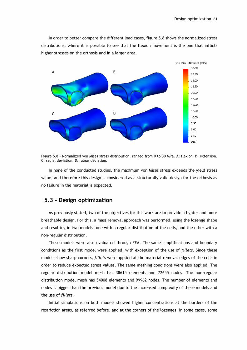
Design optimization 61
In order to better compare the different load cases, figure 5.8 shows the normalized stress
distributions, where it is possible to see that the flexion movement is the one that inflicts
higher stresses on the orthosis and in a larger area.
Figure 5.8 – Normalized von Mises stress distribution, ranged from 0 to 30 MPa. A: flexion. B: extension. C: radial deviation. D: ulnar deviation.
In none of the conducted studies, the maximum von Mises stress exceeds the yield stress
value, and therefore this design is considered as a structurally valid design for the orthosis as
no failure in the material is expected.
5.3 - Design optimization
As previously stated, two of the objectives for this work are to provide a lighter and more
breathable design. For this, a mass removal approach was performed, using the lozenge shape
and resulting in two models: one with a regular distribution of the cells, and the other with a
non-regular distribution.
These models were also evaluated through FEA. The same simplifications and boundary
conditions as the first model were applied, with exception of the use of fillets. Since these
models show sharp corners, fillets were applied at the material removal edges of the cells in
order to reduce expected stress values. The same meshing conditions were also applied. The
regular distribution model mesh has 38615 elements and 72655 nodes. The non-regular
distribution model mesh has 54008 elements and 99962 nodes. The number of elements and
nodes is bigger than the previous model due to the increased complexity of these models and
the use of fillets.
Initial simulations on both models showed higher concentrations at the borders of the
restriction areas, as referred before, and at the corners of the lozenges. In some cases, some
A B
C D
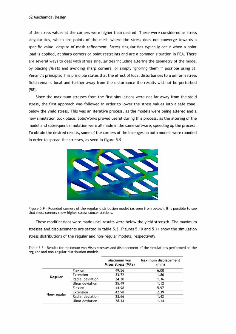
62 Mechanical Design
of the stress values at the corners were higher than desired. These were considered as stress
singularities, which are points of the mesh where the stress does not converge towards a
specific value, despite of mesh refinement. Stress singularities typically occur when a point
load is applied, at sharp corners or point restraints and are a common situation in FEA. There
are several ways to deal with stress singularities including altering the geometry of the model
by placing fillets and avoiding sharp corners, or simply ignoring them if possible using St.
Venant’s principle. This principle states that the effect of local disturbances to a uniform stress
field remains local and further away from the disturbance the results will not be perturbed
[98].
Since the maximum stresses from the first simulations were not far away from the yield
stress, the first approach was followed in order to lower the stress values into a safe zone,
below the yield stress. This was an iterative process, as the models were being altered and a
new simulation took place. SolidWorks proved useful during this process, as the altering of the
model and subsequent simulation were all made in the same software, speeding up the process.
To obtain the desired results, some of the corners of the lozenges on both models were rounded
in order to spread the stresses, as seen in figure 5.9.
Figure 5.9 – Rounded corners of the regular distribution model (as seen from below). It is possible to see that most corners show higher stress concentrations.
These modifications were made until results were below the yield strength. The maximum
stresses and displacements are stated in table 5.3. Figures 5.10 and 5.11 show the simulation
stress distributions of the regular and non-regular models, respectively.
Table 5.3 – Results for maximum von Mises stresses and displacement of the simulations performed on the regular and non-regular distribution models.
Maximum von
Mises stress (MPa) Maximum displacement
(mm)
Regular
Flexion 49.56 6.00
Extension 33.72 1.80
Radial deviation 24.30 1.36
Ulnar deviation 25.49 1.12
Non-regular
Flexion 44.98 5.97
Extension 42.98 2.39
Radial deviation 23.66 1.42
Ulnar deviation 28.14 1.14
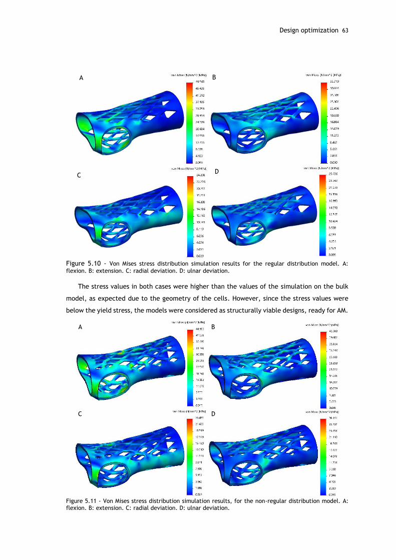
Design optimization 63
Figure 5.10 - Von Mises stress distribution simulation results for the regular distribution model. A:
flexion. B: extension. C: radial deviation. D: ulnar deviation.
The stress values in both cases were higher than the values of the simulation on the bulk
model, as expected due to the geometry of the cells. However, since the stress values were
below the yield stress, the models were considered as structurally viable designs, ready for AM.
Figure 5.11 - Von Mises stress distribution simulation results, for the non-regular distribution model. A: flexion. B: extension. C: radial deviation. D: ulnar deviation.
A B
CD
A B
C D

Chapter 6
Additive Manufacturing
The final step of the proposed methodology consists of acquiring the orthotic device
through the use of AM technologies. This chapter provides a comparative study for the three
obtained prototypes, comprising two different processes and three different materials. In each
case, the pre-processing, printing, post-processing and resultant prototypes are explained and
evaluated. A comparison between the three prototypes is made regarding their characteristics
and associated advantages and disadvantages.
6.1 - First prototype
The first prototype was obtained using SL process and corresponds to the first version of
the orthosis model. Form 2 equipment was used and the chosen material was the Tough Resin
from the same manufacturer.
Before proceeding with the printing itself, a pre-processing was required and guaranteed
by the software provided by the manufacturer, PreForm. This software automatically rotates,
translates and positions the objects in order to optimize the printing. It also generates the
needed support structures to ensure a clean print (figure 6.1-A). Due to printing size
limitations, the parts were not printed in a vertical position, which ended up requiring for a
higher number of supports.
As seen in figure 6.1-B, the layers were built upside down with a 50 micron resolution, and
the resulting structure was removed from the plate and the supports were manually removed.
In some cases, the supports left some small prominences on the surface at the point where
they were attached to the model (figure 6.1-C). The green parts were then cured in a UV light
chamber (figure 6.1-D). This cure was made for 3 hours at 70°C. The parts were finally sanded
mostly at the edges to facilitate the fit and diminish the support prominences.
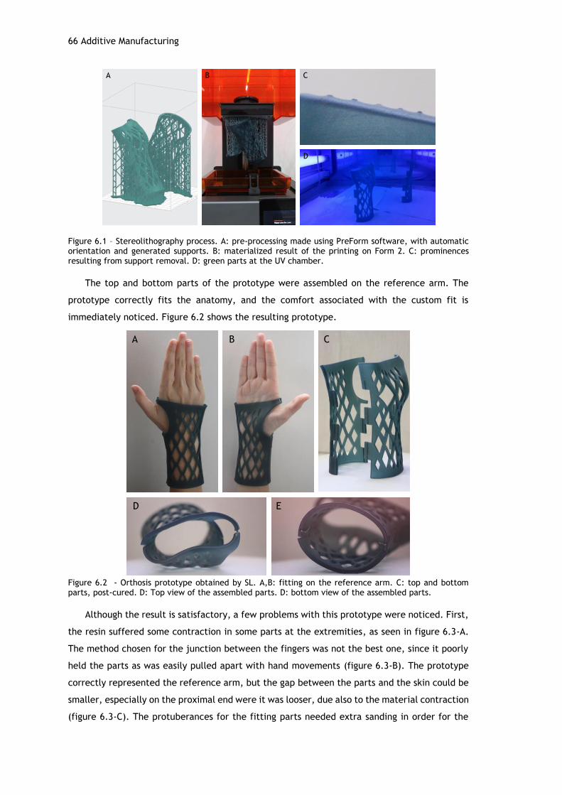
66 Additive Manufacturing
Figure 6.1 – Stereolithography process. A: pre-processing made using PreForm software, with automatic orientation and generated supports. B: materialized result of the printing on Form 2. C: prominences resulting from support removal. D: green parts at the UV chamber.
The top and bottom parts of the prototype were assembled on the reference arm. The
prototype correctly fits the anatomy, and the comfort associated with the custom fit is
immediately noticed. Figure 6.2 shows the resulting prototype.
Figure 6.2 - Orthosis prototype obtained by SL. A,B: fitting on the reference arm. C: top and bottom parts, post-cured. D: Top view of the assembled parts. D: bottom view of the assembled parts.
Although the result is satisfactory, a few problems with this prototype were noticed. First,
the resin suffered some contraction in some parts at the extremities, as seen in figure 6.3-A.
The method chosen for the junction between the fingers was not the best one, since it poorly
held the parts as was easily pulled apart with hand movements (figure 6.3-B). The prototype
correctly represented the reference arm, but the gap between the parts and the skin could be
smaller, especially on the proximal end were it was looser, due also to the material contraction
(figure 6.3-C). The protuberances for the fitting parts needed extra sanding in order for the
A B C
D
A B C
D E
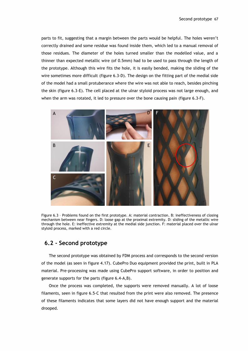
Second prototype 67
parts to fit, suggesting that a margin between the parts would be helpful. The holes weren’t
correctly drained and some residue was found inside them, which led to a manual removal of
those residues. The diameter of the holes turned smaller than the modelled value, and a
thinner than expected metallic wire (of 0.5mm) had to be used to pass through the length of
the prototype. Although this wire fits the hole, it is easily bended, making the sliding of the
wire sometimes more difficult (figure 6.3-D). The design on the fitting part of the medial side
of the model had a small protuberance where the wire was not able to reach, besides pinching
the skin (figure 6.3-E). The cell placed at the ulnar styloid process was not large enough, and
when the arm was rotated, it led to pressure over the bone causing pain (figure 6.3-F).
Figure 6.3 – Problems found on the first prototype. A: material contraction. B: ineffectiveness of closing mechanism between near fingers. D: loose gap at the proximal extremity. D: sliding of the metallic wire through the hole. E: ineffective extremity at the medial side junction. F: material placed over the ulnar styloid process, marked with a red circle.
6.2 - Second prototype
The second prototype was obtained by FDM process and corresponds to the second version
of the model (as seen in figure 4.17). CubePro Duo equipment provided the print, built in PLA
material. Pre-processing was made using CubePro support software, in order to position and
generate supports for the parts (figure 6.4-A,B).
Once the process was completed, the supports were removed manually. A lot of loose
filaments, seen in figure 6.5-C that resulted from the print were also removed. The presence
of these filaments indicates that some layers did not have enough support and the material
drooped.
A
B
C
FD
E

68 Additive Manufacturing
Figure 6.4 – Fused deposition modelling process. A: pre-processing made at support software, where supports were added. B: printer head depositing material. C: top and bottom parts after printing; supports and loose filaments are visible.
The top and bottom parts of the prototype were assembled on the reference arm (figure
6.5). This prototype also comfortably fits the anatomy. However, the part corresponding to the
junction between the fingers was not correctly printed due most probably to support issues,
resulting in a missing portion of the prototype as seen in figure 6.5-B.
Figure 6.5 - Orthosis prototype obtained by FDM. A: fitting on the reference arm, palmar view. B: fitting on the reference arm, dorsal view; the missing portion is visible. C: top and bottom parts, post-cured. D: top view of the assembled parts. D: bottom view of the assembled parts, where the grooves made to accommodate the metal wire are visible.
A B
C
A B C
D E
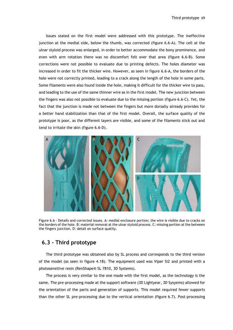
Third prototype 69
Issues stated on the first model were addressed with this prototype. The ineffective
junction at the medial side, below the thumb, was corrected (figure 6.6-A). The cell at the
ulnar styloid process was enlarged, in order to better accommodate the bony prominence, and
even with arm rotation there was no discomfort felt over that area (figure 6.6-B). Some
corrections were not possible to evaluate due to printing defects. The holes diameter was
increased in order to fit the thicker wire. However, as seen in figure 6.6-A, the borders of the
hole were not correctly printed, leading to a crack along the length of the hole in some parts.
Some filaments were also found inside the hole, making it difficult for the thicker wire to pass,
and leading to the use of the same thinner wire as in the first model. The new junction between
the fingers was also not possible to evaluate due to the missing portion (figure 6.6-C). Yet, the
fact that the junction is made not between the fingers but more dorsally already provides for
a better hand stabilization than that of the first model. Overall, the surface quality of the
prototype is poor, as the different layers are visible, and some of the filaments stick out and
tend to irritate the skin (figure 6.6-D).
Figure 6.6 – Details and corrected issues. A: medial enclosure portion; the wire is visible due to cracks on the borders of the hole. B: material removal at the ulnar styloid process. C: missing portion at the between the fingers junction. D: detail on surface quality.
6.3 - Third prototype
The third prototype was obtained also by SL process and corresponds to the third version
of the model (as seen in figure 4.18). The equipment used was Viper Si2 and printed with a
photosensitive resin (RenShape® SL 7810, 3D Systems).
The process is very similar to the one made with the first model, as the technology is the
same. The pre-processing made at the support software (3D Lightyear, 3D Sysyems) allowed for
the orientation of the parts and generation of supports. This model required fewer supports
than the other SL pre-processing due to the vertical orientation (figure 6.7). Post-processing
C
D
A B
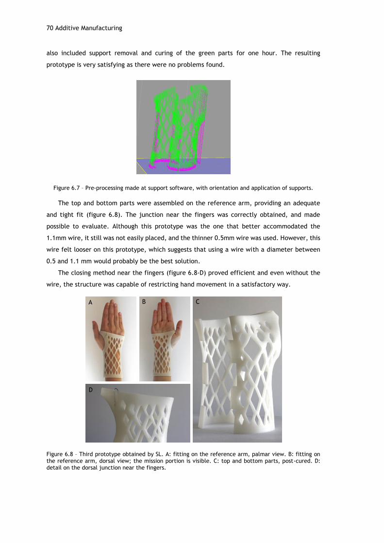
70 Additive Manufacturing
also included support removal and curing of the green parts for one hour. The resulting
prototype is very satisfying as there were no problems found.
Figure 6.7 – Pre-processing made at support software, with orientation and application of supports.
The top and bottom parts were assembled on the reference arm, providing an adequate
and tight fit (figure 6.8). The junction near the fingers was correctly obtained, and made
possible to evaluate. Although this prototype was the one that better accommodated the
1.1mm wire, it still was not easily placed, and the thinner 0.5mm wire was used. However, this
wire felt looser on this prototype, which suggests that using a wire with a diameter between
0.5 and 1.1 mm would probably be the best solution.
The closing method near the fingers (figure 6.8-D) proved efficient and even without the
wire, the structure was capable of restricting hand movement in a satisfactory way.
Figure 6.8 – Third prototype obtained by SL. A: fitting on the reference arm, palmar view. B: fitting on the reference arm, dorsal view; the mission portion is visible. C: top and bottom parts, post-cured. D: detail on the dorsal junction near the fingers.
A B C
D
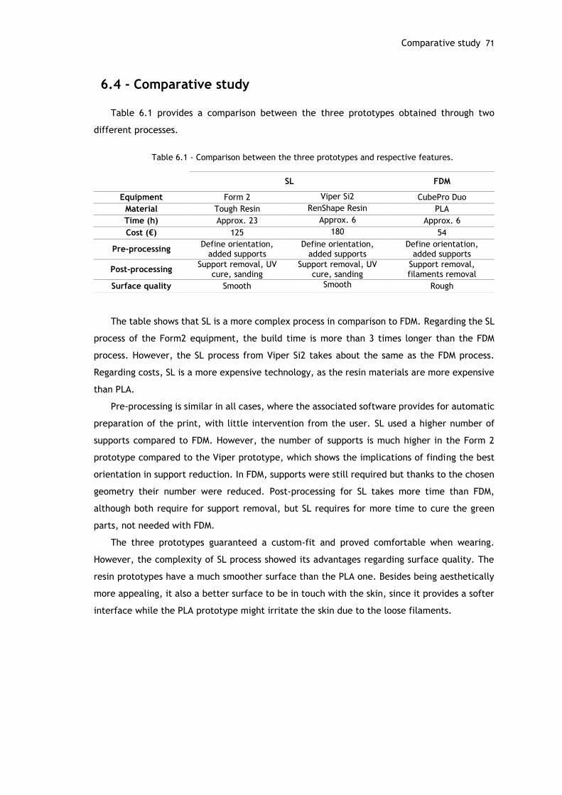
Comparative study 71
6.4 - Comparative study
Table 6.1 provides a comparison between the three prototypes obtained through two
different processes.
Table 6.1 - Comparison between the three prototypes and respective features.
The table shows that SL is a more complex process in comparison to FDM. Regarding the SL
process of the Form2 equipment, the build time is more than 3 times longer than the FDM
process. However, the SL process from Viper Si2 takes about the same as the FDM process.
Regarding costs, SL is a more expensive technology, as the resin materials are more expensive
than PLA.
Pre-processing is similar in all cases, where the associated software provides for automatic
preparation of the print, with little intervention from the user. SL used a higher number of
supports compared to FDM. However, the number of supports is much higher in the Form 2
prototype compared to the Viper prototype, which shows the implications of finding the best
orientation in support reduction. In FDM, supports were still required but thanks to the chosen
geometry their number were reduced. Post-processing for SL takes more time than FDM,
although both require for support removal, but SL requires for more time to cure the green
parts, not needed with FDM.
The three prototypes guaranteed a custom-fit and proved comfortable when wearing.
However, the complexity of SL process showed its advantages regarding surface quality. The
resin prototypes have a much smoother surface than the PLA one. Besides being aesthetically
more appealing, it also a better surface to be in touch with the skin, since it provides a softer
interface while the PLA prototype might irritate the skin due to the loose filaments.
SL FDM
Equipment Form 2 Viper Si2 CubePro Duo
Material Tough Resin RenShape Resin PLA
Time (h) Approx. 23 Approx. 6 Approx. 6
Cost (€) 125 180 54
Pre-processing Define orientation,
added supports Define orientation,
added supports Define orientation,
added supports
Post-processing Support removal, UV
cure, sanding Support removal, UV
cure, sanding Support removal, filaments removal
Surface quality Smooth Smooth Rough

Chapter 7
Conclusions and Future Work
The hand and wrist form a complex and essential structure to our daily lives. However, this
complexity associated to the delicate structure of the bones, joints and ligaments makes the
hand and wrist prone to several types of injuries. Orthoses are commonly used as a complement
to therapy and with various purposes, not only for the upper limb but to almost every part of
the body. Patients are presented with a vast offer of orthoses, varying in type, material, costs
and fabrication process. However, in spite of the different possibilities, current solutions are
still not ideal as they do not reflect the progress made by new manufacturing technologies,
particularly AM.
This work aimed to contribute to the study of orthosis fabrication using CAE methods and
AM for product fabrication. The several steps of the proposed methodology proved efficient,
culminating with prototype fabrication and evaluation.
An initial step regarding the clinical background, with particular emphasis on patient
diagnosis, is of most importance to provide a customized treatment. This evaluation should be
performed by a specialized clinician in order to guarantee the correct specifications for the
orthosis.
Tridimensional scanning proved to be an effective method to obtain patient anatomy,
avoiding for the time consuming and messy plaster models. Supports may be used in order to
increase patient comfort and stabilization during the digitalization. The resulting 3D model is
capable of accurately describe the anatomy, and it is easy to share and store for future
utilization.
Orthosis modelling using SolidWorks was capable of designing an efficient model. Although
this process took several days to complete, it could be performed in several hours, considering
a skilled and prepared design engineer. FEA was proved as a useful tool for evaluating structure
viability and analyzing mass removal approaches. The chosen geometry contributed in the
reduction of supports, particularly for FDM, and could be an important feature to consider in
order to reduce costs.
74 Conclusions and Future Work
The proposed approach is validated experimentally with the assembly of the prototypes on
the reference arm which highly satisfy the fit requirement. The resin prototypes, obtained by
SL, provided the best overall quality, but are also the most expensive.
The main goals of this work were therefore achieved. The proposed orthosis meets the
custom-fit requirements, and provides for a comfortable wear. It is also light weight and
relatively thin. The geometry allows for breathing of the skin, avoiding excessive perspiration.
Although subjective, aesthetics is also improved thanks to a more advanced take on the design
and manufacturing process.
AM is therefore proved as a viable option for the production of orthoses, alongside with
other digital methods like CAD and CAE. Although more research needs to be done regarding
associated costs, the studied processes represent a competitive option for traditional custom-
made orthoses.
These promising results were worth publishing, as stated previously, however further
possible developments were identified as future work in order to improve the orthosis. First,
it would be of interest to develop a different method for the enclosure of the two parts.
Although the proposed method provides a secure fit, it might not be adequate for patients with
hand impairment. Ideally, this closing method should not need extra materials besides that of
the print, thus exploring as much as possible the possibilities delivered by AM.
Other types of designs could also be explored. This could be made regarding mass removal,
where the chosen pattern could meet the preferences of the patient and therefore making it
more appealing and personalized. Regarding the design itself, different takes on the model
could be performed, opting for a minimalist design, for example, and thus minimizing
furthermore the weight and volume of the orthosis. Orthoses for other types of upper limb
pathologies could also be explored. A more thorough study on the available AM processes is still
needed to find the best option regarding quality and cost of the orthosis and in order to provide
competitive prices.
Finally, establishing collaboration protocols with rehabilitation centers such as CRPG would
bring valuable contributions for the development of this research as well as for the patients
that would benefit from the correspondent outcomes.
75
References
[1] E. E. Fess, K. S. Gettle, C. A. Philips, and J. R. Janson, Hand and Upper Extremity
Splinting, Third. Elsevier Health Sciences, 2005.
[2] A. M. Paterson, R. Bibb, R. I. Campbell, and G. Bingham, “Comparing additive
manufacturing technologies for customised wrist splints.,” Rapid Prototyp. J., vol. 21,
no. 3, pp. 230–243, 2015.
[3] a. M. Paterson, R. J. Bibb, and R. I. Campbell, “Evaluation of a digitised splinting
approach with multiple-material functionality using Additive Manufacturing
technologies,” Proc. Solid Free. Fabr. Symp., pp. 656–672, 2012.
[4] E. Taylor, J. Hanna, and H. J. C. R. Belcher, “Splinting of the hand and wrist,” Curr.
Orthop., vol. 17, no. 6, pp. 465–474, 2003.
[5] M. Veehof, “MEASURING TREATMENT RESPONSE IN RHEUMATOID ARTHRITIS The use of
patient-reported outcome measures,” 2008.
[6] IndustryArc, “Global Orthotic Devices Market Analysis and Forecast,” 2014.
[7] S. H. Huang, P. Liu, A. Mokasdar, and L. Hou, “Additive manufacturing and its societal
impact: A literature review,” Int. J. Adv. Manuf. Technol., vol. 67, no. 5–8, pp. 1191–
1203, 2013.
[8] N. Guo and M. C. Leu, “Additive manufacturing: Technology, applications and research
needs,” Front. Mech. Eng., vol. 8, no. 3, pp. 215–243, 2013.
[9] R. Belknap, “Four Reasons to Use Additive Manufacturing in Medical Device
Development,” MedTech Intelligence, 2015. [Online]. Available:
https://www.medtechintelligence.com/feature_article/four-reasons-to-use-additive-
manufacturing-in-medical-device-development/.
[10] S. Telfer, J. Pallari, J. Munguia, K. Dalgarno, M. McGeough, and J. Woodburn,
“Embracing additive manufacture: implications for foot and ankle orthosis design,” BMC
Musculoskelet. Disord., vol. 13, no. 1, p. 84, 2012.
[11] D. Palousek, J. Rosicky, D. Koutny, P. Stoklásek, and T. Navrat, “Pilot study of the wrist
orthosis design process,” Rapid Prototyp. J., vol. 20, no. 1, pp. 27–32, 2013.
[12] Y. A. Jin, J. Plott, R. Chen, J. Wensman, and A. Shih, “Additive manufacturing of custom
orthoses and prostheses - A review,” Procedia CIRP, vol. 36, pp. 199–204, 2015.
[13] G. H. Snyder, M. J. Cotteleer, and B. Kotek, “3D opportunity in medical technology,”
Deloitte University Press, 2014. [Online]. Available:
http://dupress.com/articles/additive-manufacturing-3d-opportunity-in-medtech/.
[14] T. Wohlers, “Additive manufacturing and 3D printing state of the industry,” 2015.
[15] C. E. Dombroski, M. E. R. Balsdon, and A. Froats, “The use of a low cost 3D scanning
and printing tool in the manufacture of custom-made foot orthoses: a preliminary
study.,” BMC Res. Notes, vol. 7, no. 1, p. 443, 2014.
[16] J. Pallari and K. Dalgarno, “Design and Additive Fabrication of Foot and Ankle-Foot
Orthoses J.,” pp. 834–845.
[17] D. Karasahin, “Osteoid.”
[18] J. Evill, “Cortex.”
[19] FATHOM, “Hashcast.” [Online]. Available: http://studiofathom.com/hashcast/.
[20] “Xkelet.”
[21] W. Hipolite, “Russian Company Looks to Bring 3D Printed Casts to Market,” 3Dprint.com,
2015.
76
[22] Huang, “Custom-Fitted 3-D Printed Wrist Braces,” Stony Brook University, 2016.
[Online]. Available: https://you.stonybrook.edu/researchtech/2016/02/01/custom-
fitted-adjustable-wrist-braces/.
[23] Thingiverse, “Wrist brace.” [Online]. Available:
http://www.thingiverse.com/thing:403001.
[24] MediPrint, “Novacast.”
[25] “ActivArmor.”
[26] “Younext.”
[27] “Zdavprint.” [Online]. Available: http://zdravprint.ru/#forwhom.
[28] H. Kim and S. Jeong, “Case study: Hybrid model for the customized wrist orthosis using
3D printing,” J. Mech. Sci. Technol., vol. 29, no. 12, pp. 5151–5156, 2015.
[29] P. B. Gove, Webster’s third new international dictionary of the english language. 1993.
[30] T. Taylor, “Hand and wrist.” [Online]. Available:
http://www.innerbody.com/image/skel13.html#full-description.
[31] C. Wadsworth, “Clinical anatomy and mechanics of the wrist and hand.,” J. Orthop.
Sports Phys. Ther., vol. 4, no. 4, pp. 206–216, 1983.
[32] “Bones of the hand and wrist,” ABC Radiology Blog. [Online]. Available:
http://abcradiology.blogspot.pt/2011/10/hand-and-wrist-brief-note.html.
[33] L. Ombregt, “Applied anatomy of the wrist, thumb and hand,” in A System of
Orthopaedic Medicine, 2013, pp. e102–e111.
[34] L. Jones and S. Lederman, “Human Hand Function,” 2006, pp. 16–18.
[35] TeachMeAnatomy, “Anatomical Terms of Movement.” [Online]. Available:
http://teachmeanatomy.info/the-basics/anatomical-terminology/terms-of-
movement/.
[36] “Learning Modules - Medical Gross Anatomy - Movements of the upper limb.” University
of Michigan, pp. 14–18.
[37] “American Society for Surgery of the Hand.” [Online]. Available: http://www.assh.org/.
[38] S. L. Delp, A. E. Grierson, and T. S. Buchanan, “Maximum isometric moments generated
by the wrist muscles in flexion-extension and radial-ulnar deviation,” J. Biomech., vol.
29, no. 10, pp. 1371–1375, 1996.
[39] J. Vanswearingen, “Measuring wrist muscle strength.,” J. Orthop. Sports Phys. Ther.,
vol. 4, no. 4, pp. 217–28, 1983.
[40] P. G. Herbert, “Evaluation and management of chronic work-related musculoskeletal
disorders of the distal upper extremity,” Am. J. Ind. Med., vol. 37, no. 1, pp. 75–93,
2000.
[41] J. J. Biundo and P. J. Rush, “Carpal Tunnel Syndrome,” American College of
Rheumatology, 2013. [Online]. Available: http://www.rheumatology.org/I-Am-
A/Patient-Caregiver/Diseases-Conditions/Carpal-Tunnel-Syndrome.
[42] “Carpal Tunnel Syndrome,” MedlinePlus. [Online]. Available:
https://medlineplus.gov/carpaltunnelsyndrome.html.
[43] E. Ruderman and S. Tambar, “Rheumatoid Arthritis,” American College of
Rheumatology, 2013. [Online]. Available: http://www.rheumatology.org/I-Am-
A/Patient-Caregiver/Diseases-Conditions/Rheumatoid-Arthritis.
[44] “Rheumatoid Arthritis,” Genetics Home Reference, 2017. [Online]. Available:
https://ghr.nlm.nih.gov/condition/rheumatoid-arthritis.
[45] J. Payne, “Tendinopathy and Tenosynovitis,” Patient, 2016. [Online]. Available:
http://patient.info/health/tendinopathy-and-tenosynovitis.
[46] J. Cluett, “What Is Wrist Tendonitis or Tenosynovitis?,” Verywell, 2016. [Online].
Available: https://www.verywell.com/wrist-tendonitis-2548611.
[47] M. D. Gomes, “Talas/Ortóteses - Fundamentos para a Prática,” Instituo Politécnico de
Leiria, 2010.
[48] S. K. M. Wong, “Classification of hand splinting.,” Hand Surg. an Int. J. devoted to hand
Up. limb Surg. Relat. Res. J. AsiaPacific Fed. Soc. Surg. Hand, vol. 7, no. 2, pp. 209–
213, 2002.
[49] C. M. Lusardi, Michelle; Jorge, Milagros; C.Nielsen, Orthotics & Prosthetics in
Rehabilition, Third. Elsevier Saunders, 2013.
[50] J. Colditz, Therapist’s management of the stiff hand. 2011.
[51] J. Bell-Krotoski, “Tissue remodeling and contracture correction using serial plaster

77
casting and orthotic positioning,” in Rehabilitation of the Hand and Upper Extremity,
2011, pp. 1599–1609.
[52] M. A. Jacobs and N. \m Austin, Splinting the Hand and Upper Extremity: Principles and
Process., no. January-March. Baltimore, 2003.
[53] J. C. Colditz, “Principles of Splinting and Splint Prescription,” in Surgery of the Hand
and Upper Extremity, .
[54] “Gauntlet Immobilization Precut Splint,” North Coast Medical & Rehabilitation
Products. [Online]. Available:
https://www.ncmedical.com/item_1089.html#!prettyPhoto.
[55] P. S. Branco and E. Al., Temas de Reabilitação: Ortóteses e outras ajudas técnicas.
2008.
[56] K. S. Schultz-Johnson, “Splinting: a problem solving approach,” in Concepts in Hand
Rehabilitation, pp. 238–71.
[57] K. S. Schultz-Johnson, “Splinting the wrist: mobilization and protection,” J. Hand Ther.
[58] Orfit, “Dynamic Orthoses and Force Application.” [Online]. Available:
http://blog.orfit.com/dynamic-orthoses-and-force-application/.
[59] “Static Progressive PIP Finger Extension Splint,” North Coast Medical & Rehabilitation
Products. [Online]. Available:
https://www.ncmedical.com/item_1043.html#!prettyPhoto.
[60] “Vacuum Station for Foot Orthotics,” Leonard Industries. [Online]. Available:
http://www.leonardindustries.com/THERMO/.
[61] A. D. Icrc, “Manufacturing Guidelines Ankle-Foot Orthosis,” 2010.
[62] Multicast, “Multicast Thermoplastic Application Tips.” [Online]. Available:
http://multi-cast.info/html/orthoticintervention.htm.
[63] R. Collier, “Orthotics work in mysterious ways,” CMAJ, vol. 183, no. 4, pp. 415–416,
2011.
[64] Healio, “New Report Offers Global Projections for Orthopedic Prosthetic and Orthotic
Markets,” O&P News, 2011. [Online]. Available: http://www.healio.com/orthotics-
prosthetics/industry-news/news/print/o-and-p-news/%7Bc2d04446-465a-4c7d-944b-
21fd57603547%7D/new-report-offers-global-projections-for-orthopedic-prosthetic-and-
orthotic-markets.
[65] C. Nielsen and I. Affecting, “O & P Trends & Statistics,” no. 39, 2010.
[66] F. Auricchio and S. Marconi, “3D printing: clinical applications in orthopaedics and
traumatology,” EFORT Open Rev., vol. 1, no. 5, pp. 121–127, 2016.
[67] A. L. Steele, “A Survey of Clinical CAD/CAM Use,” Journal of Prosthetics and Orthotics,
vol. 6, no. 2. pp. 42–47, 1994.
[68] O. Ciobanu, W. Xu, and G. Ciobanu, “The Use of 3D Scanning and Rapid Prototyping In
Medical Engineering,” Acad. Brâncuşi, no. 1, pp. 241–247, 2013.
[69] A. M. J. Paterson, R. J. Bibb, and R. I. Campbell, “A review of existing anatomical data
capture methods to support the mass customisation of wrist splints,” J. Virtual Phisical
Prototyp., vol. 5, no. 4, pp. 201–207, 2010.
[70] C. H. Kau, A. Zhurov, L. Hunter, S. Richmond, and R. Bibb, “The investigation of the
changing facial appearance of identical twins employing a three-dimensional laser
imaging system,” Orthod. Craniofacial Res., vol. 8, no. 2, pp. 85–90, 2005.
[71] J. Wohl, “Digitizer Education | Part 3: Materials for 3D Scanning,” MakerBot, 2013.
[Online]. Available: https://www.makerbot.com/media-center/2013/11/08/digitizer-
education-part-3-materials-for-3d-scanning?ab=toughpla&utm_expid=65420830-
9.lUwf5r7YS8GRRM_QNCgAMw.1&utm_referrer=https%3A%2F%2Fwww.google.pt%2F.
[72] “Everything about markers and how they help 3D scanning,” Thor3D. [Online].
Available: http://www.thaiber.se/wp-
content/uploads/2016/02/Everything_about_markers.pdf.
[73] K. L. N. M.M.M. Sarcar, K. Mallikarjuna Rao, Computer Aided Design and Manufacturing.
2008.
[74] Siemens, “CAE / Computer-Aided Engineering.” [Online]. Available:
https://www.plm.automation.siemens.com/en/plm/cae.shtml.
[75] B. O. Saracoglu and S. Gozlu, “Identification of technology performance criteria for
CAD/CAM/CAE/CIM/CAL in shipbuilding industry,” Portl. Int. Conf. Manag. Eng.
78
Technol., vol. 4, pp. 1635–1646, 2006.
[76] T. Y. Chao, W. K. Chow, and H. Kong, “A review on the applications of finite element
method to heat transfer and fluid flow,” Int. J. Archit. Sci., vol. 3, no. 1, pp. 1–19,
2002.
[77] J. N. Reddy, “An Introduction to The Finite Element Method Department of Mechanical
Engineering,” Mech. Eng., p. 420, 2005.
[78] P. M. Kurowski, “What is calculated in FEA?,” pp. 1–3, 2012.
[79] ASTM, Standard Terminology for Additive Manufacturing Technologies. 2015, pp. 20–
22.
[80] K. V. Wong and A. Hernandez, “A Review of Additive Manufacturing,” ISRN Mech. Eng.,
vol. 2012, pp. 1–10, 2012.
[81] D. Dimitrov, K. Schreve, and N. De Beer, “Advances in three dimensional printing - state
of the art and future perspectives,” Rapid Prototyp. J., vol. 12, no. 3, pp. 136–147,
2006.
[82] CustomPartNet, “Stereolithography.”
[83] CustomPartNet, “Fused Deposition Modeling.” [Online]. Available:
http://www.custompartnet.com/wu/fused-deposition-modeling.
[84] A. D. de M. M. Silva, “Estudo das potencialidades da impressão 3D no apoio ao fabrico
de sapatos para pessoas com paralisia cerebral,” Faculdade de Engenharia da
Universidade do Porto, 2015.
[85] S. A. C. Abreu, “Impressão 3D baixo custo versus impressão em equipamentos de elevado
custo,” Faculdade de Engenharia da Universidade do Porto, 2015.
[86] M. Nobel, “Product Concept Generation.” [Online]. Available:
http://sites.tufts.edu/eeseniordesignhandbook/2013/product-concept-generation/.
[87] A. A. Signore, “Conceptual project planning from an owner’s perspective,” Proj. Manag.
J., 1985.
[88] R. M. Duncan, “Basic principles of splinting the hand.,” Phys. Ther., vol. 69, no. 12, pp.
1104–1116, 1989.
[89] “Top 5 design principles for 3D Printing,” OnShape, 2016. [Online]. Available:
https://www.onshape.com/cad-blog/top-5-tips-for-designing-for-3d-printing.
[90] “3D Design for 3D Printing,” Instructables. [Online]. Available:
http://www.instructables.com/id/3D-Design-For-3D-Printing/step2/Overhangs-Part-1-
Holes/.
[91] Formlabs, “Formlabs Design Guide,” pp. 3–5, 2016.
[92] P. Systems, “Converting cad files to stl,” pp. 3–5.
[93] Laurens van Lieshout, “STL-file,” 2014. [Online]. Available:
https://commons.wikimedia.org/wiki/File:The_differences_between_CAD_and_STL_M
odels.svg.
[94] J. Thornton, “FEA and the Question of Credibility,” 2011. [Online]. Available:
https://www.asme.org/engineering-topics/articles/finite-element-analysis/fea-and-
the-question-of-credibility.
[95] FEMtools, “Finite Element Model Validation and Mesh Refinement.” [Online]. Available:
http://www.femtools.com/solutions/updating.htm.
[96] SolidWorks, “Study Types.” [Online]. Available:
http://help.solidworks.com/2012/English/SolidWorks/cworks/Study_Types.htm.
[97] Autodesk, “How to Perform a Mesh Convergence Study,” 2015. [Online]. Available:
https://knowledge.autodesk.com/support/simulation-
mechanical/troubleshooting/caas/sfdcarticles/sfdcarticles/How-to-Perform-a-Mesh-
Convergence-Study.html.
[98] M. Acin, “Stress singularities, stress concentrations and mesh convergence,” 2015.
[Online]. Available: http://www.acin.net/2015/06/02/stress-singularities-stress-
concentrations-and-mesh-convergence/.

79
Appendix A
Article presented at the 7th Portuguese Congress on Biomechanics (CNB2017), entitled
“Additive manufacturing of custom-fit orthoses for the upper limb”.
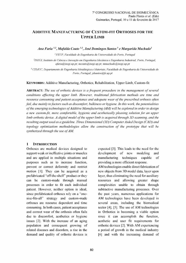
80
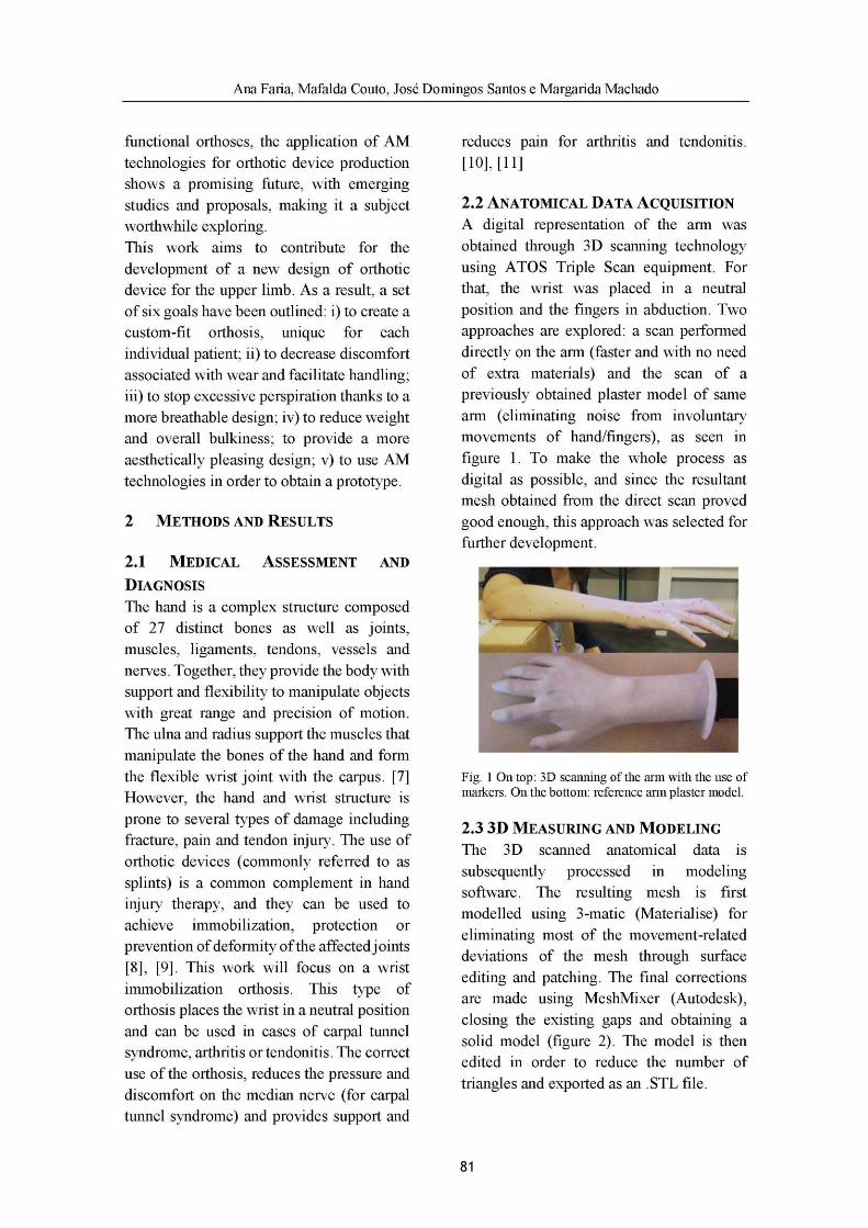
81
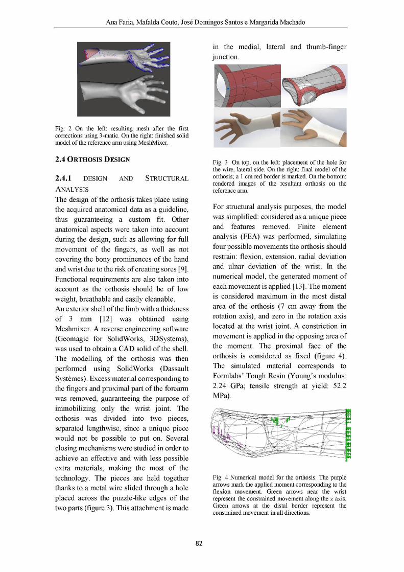
82
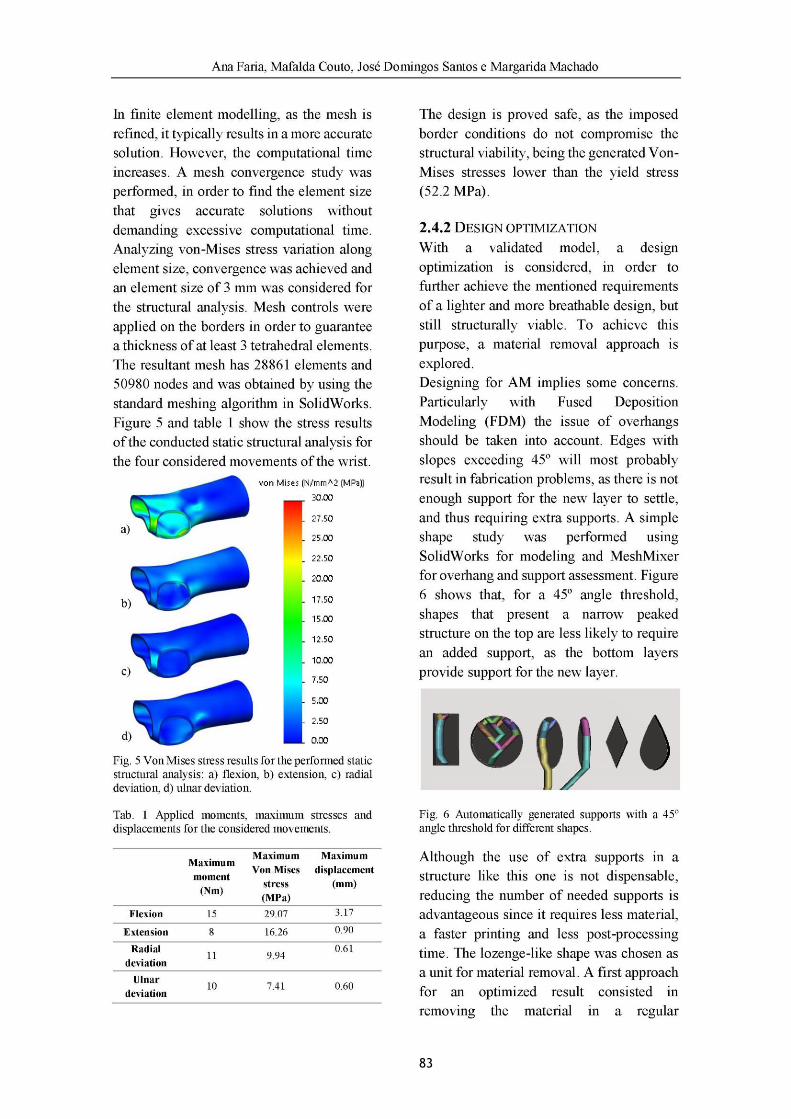
83
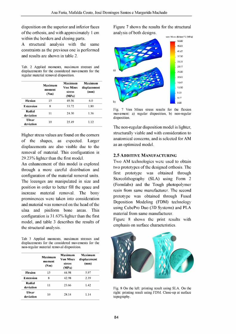
84
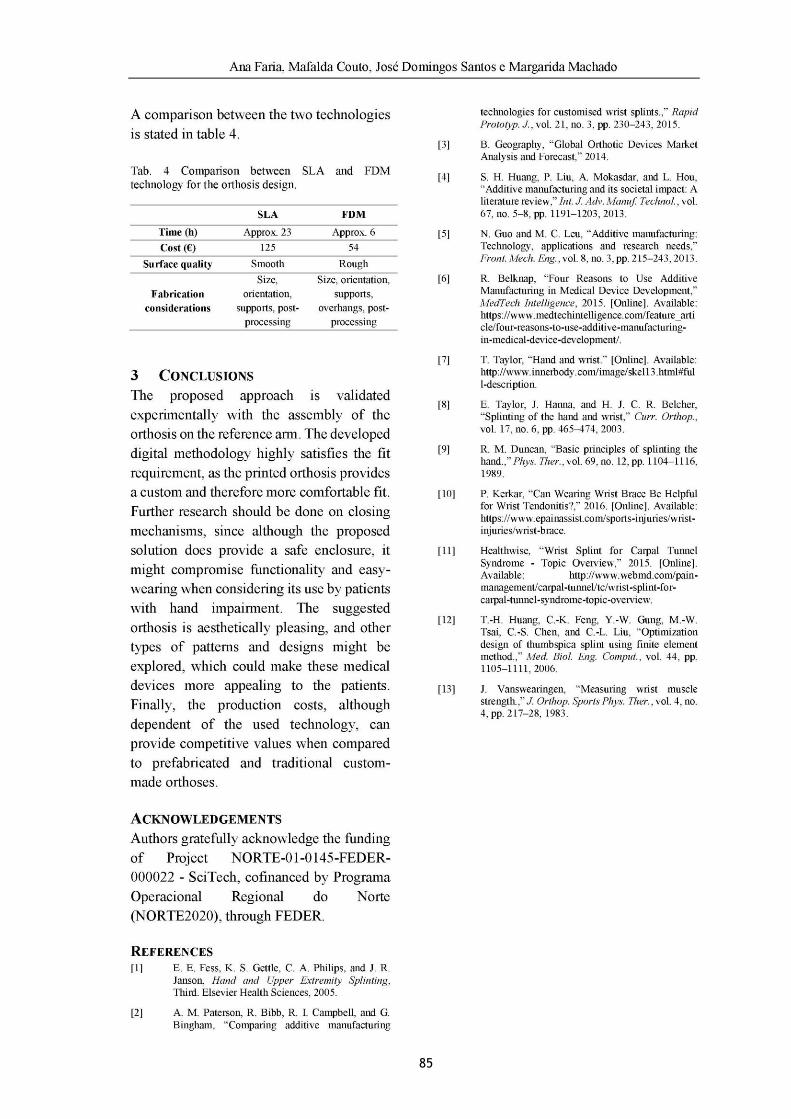
85

86

87
Appendix B
Honorable mention received at the 7th Portuguese Congress on Biomechanics for the
presented work.
88
89
Appendix C
The author gratefully acknowledges the funding of Project NORTE-01-0145-FEDER-000022 -
SciTech - Science and Technology for Competitive and Sustainable Industries, cofinanced by
Programa Operacional Regional do Norte (NORTE2020), through Fundo Europeu de
Desenvolvimento Regional (FEDER).