Embed Size (px)
Citation preview

CAMX Conference Proceedings. Dallas, TX, October 26-29, 2015. CAMX – The Composites and Advanced Materials Expo.
ADDITIVE MANUFACTURING AND CHARACTERIZATION OF
ULTEM POLYMERS AND COMPOSITES
Kathy C. Chuang, Joseph E. Grady and Robert D. Draper
NASA Glenn Research Center, Cleveland, OH
Euy-Sik E. Shin
Ohio Aerospace Institute, Cleveland, OH
Clark Patterson and Thomas D. Santelle
Rapid Prototype Plus Manufacturing (rp+m), Avon Lake, OH
ABSTRACT
The objective of this project was to conduct additive manufacturing to produce aircraft engine
components by Fused Deposition Modeling (FDM), using commercially available
polyetherimides – Ultem 9085 and experimental Ultem 1000 mixed with 10% chopped carbon
fiber. A property comparison between FDM-printed and injection-molded coupons for Ultem
9085, Ultem 1000 resin and the fiber-filled composite Ultem 1000 was carried out. Furthermore,
an acoustic liner was printed from Ultem 9085 simulating conventional honeycomb structured
liners and tested in a wind tunnel. Composite compressor inlet guide vanes were also printed
using fiber-filled Ultem 1000 filaments and tested in a cascade rig. The fiber-filled Ultem 1000
filaments and composite vanes were characterized by scanning electron microscope (SEM) and
acid digestion to determine the porosity of FDM-printed articles which ranged from 25-31%.
Coupons of Ultem 9085 and experimental Ultem 1000 composites were tested at room
temperature and 400°F to evaluate their corresponding mechanical properties.
1. INTRODUCTION
Additive manufacturing (AM) has gained considerable attention recently, because of the promise
of being able to produce net shape 3D components layer by layer directly by automated
machines. This is especially true for complex shape polymer parts and low production volume
components, which are not economical to produce by injection molding. In addition, AM offers
quick turn- around time for specialty parts and shortened production and testing cycle for
components. This project concentrated on Fused Deposition Modeling (FDM) technique (Fig. 1)
in which a polymer filament is melted and then deposited in successive layers to build a 3D
component according to a computer-aided design (CAD) file [1]. The state-of-the art of FDM are
populated with commercial ABS (acrylonitrile butadiene styrene), polycarbonate [2] and
polyamides such as Nylons for use as prototyping at the temperature around 100-125 °C (212-
257° F).
* This paper is declared a work of the U.S. Government and is not subject to copyright
protection in the United States.
https://ntrs.nasa.gov/search.jsp?R=20160001352 2018-08-26T05:16:42+00:00Z

Figure 1. Schematic of Fused Deposition Modeling (FDM) process.
The objective of the project was to develop additive manufacturing approaches for polymeric
aircraft engine components and conduct testing on coupons as well as built parts, such as
acoustic testing in a wind tunnel. The Ultem 9085 polyetherimide filament is one of the
commercial polymers marketed by Stratasys for use in FDM with a glass transition temperature
(Tg) of 186 ºC (367 °F). Ultem 9085 is certified by FAA as flame retardant polymer for use in
aircraft cabin. This project used Ultem 9085 as the baseline polymer for printing demonstration
components, such as acoustic liners and a perforated engine access door. Furthermore, this
project also strived to advance the FDM process into building polymer composites for aircraft
engine parts. These additively manufactured components were tested in rigs and results have
been presented in the first part of the report [3]. The Ultem 1000 with 10% AS4 carbon fiber was
chosen as the candidate fiber-filled polymer filaments for this project, because Stratasys is
making it available for the first time as an experimental filament under the State funded Ohio
Third Frontier research project. Ultem 1000 is a homopolymer with higher Tg (217 °C, 423 °F)
than that of Ultem 9085 which is a blend of polycarbonate and Ultem 1000 with lower viscosity
and cost suitable for injection molding.
2. EXPERIMENTATION
All the FDM printing was performed at Rapid Prototype Plus Manufacturing (rp+m), using
Stratasys’ open source Fortus 400mc or 900mc FDM machines. The experimental XH6050 resin
and carbon-fiber-filled Ultem 1000 filaments were supplied by Stratasys under the Ohio Third
Frontier Program — Advanced Materials for Additive Manufacturing Maturation. The Ultem
resins and composites were printed between 375-420 °C (707-788 °F). The specific engine
components were selected by Honeywell Aerospace. Using Ultem 9085, a perforated engine
door (Fig. 2a), an acoustic liner and its demonstration components (Fig. 2b) with 93 °C (200 °F)
use temperature were printed by FDM at 375 °C in one piece, simulating the Aramid honeycomb
structures bonded with epoxy composite face sheet. Additionally, composite vanes (Fig. 2c)
with use temperature up to 204 °C (400°F) were printed at 420 °C, using Ultem 1000 filled with
10% chopped AS4 carbon fibers. Rig testing conditions and results of acoustic liner and
composite inlet guide vane (IGV) are described in details in the first part of the report [3].

Perforated engine access door b) Acoustic liner and components c) Composite vanes
(Ultem 9085) (Ultem 9085) Ultem 1000/fiber
Figure 2. FDM printed polymer components
3. RESULTS AND DISCUSSION
3.1 Property Comparison of FDM and Injection Molding
A mechanical property comparison between FDM-printed and injection-molded coupons of
Ultem 9085, Ultem 1000 and the carbon-fiber-filled Ultem 1000 are shown in Table 1. These
data indicated that Ultem 9085 (printed at 0° raster angle), displayed about 87% of tensile
strength and 64% of modulus, as compared to the injection molded counter parts, due to the
presence of inherent porosities within the FDM-printed test coupons. The porosity of FDM-
printed Ultem 9085 was about 5-8%, depending on the orientation of the layup. The mechanical
strength of FDM generated specimens also relied on the built direction, the thickness of the
filaments, the tool path generation and the air gap between raster in the filled pattern. In general,
the FDM generated structures are more brittle and have lower elongation than the injection
molded counterparts [4].
Table 1. Property Comparison of Ultem 9085 and Ultem 1000 by Injection Molding vs
FDM
esin type
Properties
Ultem 9085 Injection
Molded (Sabic data)
Ultem 9085 FDM printed (Stratasys data) 0°
Ultem 9085 FDM rp+m
(GRC tested) ±45°
Ultem 1000 Injection
Molded (Sabic data)
Ultem 1000+10wt% AS4 chopped C-fiber
FDM rp+m (GRC tested) 0°/±45°
Tensile Strength (MPa)
83 72 62 ± 0.1 110 50±0.9/44±0.3
Tensile Modulus (MPa)
3,432 2,200 2,230 ± 12 3,579 2,901±48/2248±46
Flexural Strength (MPa)
137 115 92 ± 2 165 tbd
Flexural Modulus (MPa)
2,913 2,500 1,901 ± 41 3,511 tbd
Compression Strength (MPa)
n/a 104 tbd n/a tbd
Compression Modulus (MPa)
n/a 1,930 1,890 ± 32 n/a tbd
*No Ultem 1000 filament for FDM is commercially available.

3.2 Initial Characterization of Carbon Fiber Filled Ultem 1000 Composites and Filaments
The initial tensile strength of 10% AS4 fiber-filled Ultem 1000 composites (first batch ever made
from Stratasys) was only about 70% of Ultem 9085 resin as printed by FDM (Fig. 3), which was
much lower than expected. The printing of ±45° raster angle reduced the strength by 80-86% as
opposed to 0°. Further investigation by acid digestion indicated that the porosity of fiber-filler
Ultem 1000 vanes ranged from 23-26%, which are unusually high (Table 2). The printing
orientation did not exhibit much difference in terms of porosity. However, the porosity
measurement based on the integration of optical microscope images (Fig. 4) ranged from 29-34%
(Table 3), which was even higher than the 23-26% porosity obtained by acid digestion.
Figure 3. Tensile properties of Ultem 9085 and fiber-filled Ultem 1000 as received
Table 2. Porosity of Fiber-Filled Ultem 1000 Composite Vanes by Acid Digestion

Figure 4. High Resolution of optical micrographs (left) and images of pore, fiber and matrix
(right) of a FDM-printed composite vane
Table 3. Porosity of composite vanes based on Optical Microscope Images
To understand the origin of high porosity in the FDM-printed fiber-filled Ultem 1000
composites, an effort was initiated to investigate the as-received thick Ultem 1000 filament filled
with 10% chopped AS4 carbon fibers, which was fed into the FDM machine. The fiber-filled
Ultem 1000 filaments were produced by mixing 6 mm AS4 chopped fibers with Ultem 1000 in
an extruder, cut into pellets, and then re-extruded into filaments at Stratasys. As shown in Fig. 5,
the longitudinal section (a) revealed that the chopped fibers were aligned with the filament axis,
and significant amounts of the fibers were further chopped into average length of 2-3 mm during
the extrusion process. The cross section (b-e) indicated that there were little voids present in the
as-received filaments in this segment of initial investigation.
Vmy1
Hmy1
High resolution optical micrographs Images assigned for pore, fiber & matrix

a) Longitudinal Section of fiber filled filament b) Cross section
c) Cross section #1 d) Cross section #2 e) Cross section #3
after removing ~1 mm after removing ~2 mm Figure 5. Photomicrographs of 10% AS4 fiber filled Ultem 1000 filaments (as received-thick)
Separately, thin filaments of fiber-filled Ultem 1000 extruded from the liquefier of Stratasys’
Fortus 400mc FDM machine at 420 ºC were collected and analyzed, since these thin filaments
were used directly for FDM printing. As shown in Fig. 6, the FDM extruded thin filaments were
full of voids in the form of blisters, due to the sudden exposure to extreme high heat.
a) Cross section#1 b) Cross section #2 c) Cross section #3
after removing ~1 mm after removing ~2 mm
Figure 6. Photomicrographs of 10% AS4 fiber filled Ultem 1000 filaments (thin)
The acid digestion values in Table 4 confirmed that this segment of as-received thick fiber-filled
filament analyzed had no porosity as confirmed by the photomicrographs in Fig. 5. The fiber
content was 9% by weight which was very close to the original formulation of 10% chopped
fibers. However, the thin FDM-extruded filaments were found to have about 31% of porosity,
which was closer to the image analysis result of 33% porosity than that of 24-26% porosity by
acid digestion of the printed vane.

Table 4. Porosity of Fiber-Filled Ultem 1000 Filaments
Balance
Mc, g Vc, cc rc, g/cc Mf, g Mm, g Vf, cc Vm, cc Vp, cc
Filament, thick 0.2753 0.2084 1.3209 0.0254 0.250 0.014 0.1968 -0.003 9% 7% -1.2%
Filament, thin 1 0.0582 0.0645 0.9029 0.0054 0.053 0.003 0.0416 0.02 9% 5% 30.9%
thin 2 0.0583 0.0653 0.8924 0.0054 0.053 0.003 0.0417 0.021 9% 5% 31.6%
FWF,
wt%
FVF,
v%
porosity,
v%
After drying
Sample ID Pycnometer Acid digestionFrom Theor. Density
* Thick filament—as received and fed into FDM machine; thin filament — extruded from FDM machine
Thermogravimetric analysis (TGA) with Fourier Transform Infrared Spectroscopy (FTIR) was
carried out to investigate the origin of blistering in Ultem 1000. As shown in Fig. 7, the major
weight loss shown in TGA up to 300 °C (572 °F) corresponded to water shown in FTIR, which
indicated that some water was trapped inside the filament, which was more difficult to remove
than the surface water. Additionally, Fig. 8 indicated that Ultem 1000 resin pellet contained
0.375% of water, and the fiber-filled Ultem 1000 filament had 0.593% of water whereas separate
TGA analysis had indicated that the chopped fiber contained 0.25% of water. These two curves
indicated that other than water loss, the Ultem resin and filament are very stable until about 500
°C (932 °F). However, the thin fiber-filled filament showed not only the loss of surface water
around 100 ºC (212 °F), but also some other weight loss due to degradation, as it had been
exposed to the sudden high temperature of 420 °C (788 °F) at the liquefier in the FDM machine
during the melting process. This first lot of the fiber-filled Ultem 1000 filament seemed to be
solid but brittle whereas the thin filament appeared to be fragile and extremely porous.
Figure 7. TGA-FTIR analysis of the fiber-filled Ultem 1000 filament
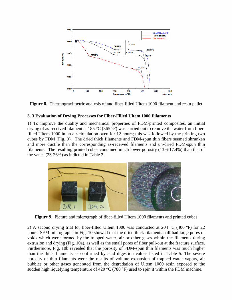
Figure 8. Thermogravimetric analysis of and fiber-filled Ultem 1000 filament and resin pellet
3. 3 Evaluation of Drying Processes for Fiber-Filled Ultem 1000 Filaments
1) To improve the quality and mechanical properties of FDM-printed composites, an initial
drying of as-received filament at 185 °C (365 °F) was carried out to remove the water from fiber-
filled Ultem 1000 in an air-circulation oven for 12 hours; this was followed by the printing two
cubes by FDM (Fig. 9). The dried thick filaments and FDM-spun thin fibers seemed shrunken
and more ductile than the corresponding as-received filaments and un-dried FDM-spun thin
filaments. The resulting printed cubes contained much lower porosity (13.6-17.4%) than that of
the vanes (23-26%) as indicted in Table 2.
Figure 9. Picture and micrograph of fiber-filled Ultem 1000 filaments and printed cubes
2) A second drying trial for fiber-filled Ultem 1000 was conducted at 204 °C (400 ºF) for 22
hours. SEM micrographs in Fig. 10 showed that the dried thick filaments still had large pores of
voids which were formed by the trapped water, air or other gases within the filaments during
extrusion and drying (Fig. 10a), as well as the small pores of fiber pull-out at the fracture surface.
Furthermore, Fig. 10b revealed that the porosity of FDM-spun thin filaments was much higher
than the thick filaments as confirmed by acid digestion values listed in Table 5. The severe
porosity of thin filaments were the results of volume expansion of trapped water vapors, air
bubbles or other gases generated from the degradation of Ultem 1000 resin exposed to the
sudden high liquefying temperature of 420 °C (788 °F) used to spin it within the FDM machine.

a) Thick filament after drying at 204 ºC (400 ºF) for 22 hours
b) FDM-spun thin filaments derived from 204 ºC dried thick filaments
Figure 10. SEM of fiber-filled Ultem 1000 filament after drying at 204 °C for 22 hours
Table 5. Porosity of Various Dried Fiber-Filled Ultem 1000 Filaments

3) A third drying process was conducted in a desiccant system at 149 °C (300 °F) for 12 hours
and characterized along with another section of as-received thick carbon-filled Ultem 1000
filaments as a repeat to investigate the uniformity and porosity of the experimental composite
filaments supplied by Stratasys. As shown in Table 5, the porosity of the fiber-filled Ultem 1000
thick filaments as-received for the second trial was 15.3% which is much higher than the void-
free in the initial as-received filaments. This clearly indicated that the porosity of experimental
fiber-filled Ultem 1000 filaments varied considerably from 0-15.3%, and the porosity remained
at 15% even after drying at 149 °C for 12 hours (Fig. 11). The photomicrographs in Fig. 10 also
confirmed that as-received fiber-filled Ultem 1000 filaments exhibited some porosity this time,
in contrast to the void-free segment shown in Fig. 4 previously. Since the moisture content of
the as-received Ultem 1000 composite filaments was only 0.6 %, including 0.2 % moisture from
as-received chopped fibers, the voids shown in the as-received fiber-filled Ultem 1000 thick
filaments could either come from moisture trapped inside or the air bubbles introduced during
the extrusion process. Nevertheless, after drying at various conditions, all the FDM-extruded
thin filaments still displayed consistent porosity of ~25%, which is similar to porosity of printed
composite vanes, but lower than the 30% porosity detected in the FDM-extruded thin filaments
derived from the undried thick filaments (Table 5). This fact clearly indicated that once the
moisture pore or air bubbles formed within the filaments, they are much more difficult to remove
than the surface water
As-Received Filament
Dried Filament
(300 °F in a Desiccant)
Ori
gin
al
FD
M
Extr
ud
ed
Figure. 11. Optical Micrographs of as-received and dried fiber-filled Ultem 1000 filaments
3.4 Mechanical Properties of FDM-Printed Ultem Resin and Ultem 1000 Composites
Tensile tests of FDM-printed Ultem 9085, Ultem 1000, XH6050 and fiber-filled Ultem 1000
coupons were conducted at room temperature and 204 °C (400 °F) as listed in Table 6. Fig. 12
showed that Ultem 1000/C-fiber composite printed with the dried FDM filament showed the
highest modulus while Ultem 9085 resin showed the highest toughness and strength at room
temperature. The carbon fiber reinforcement Ultem 1000 was estimated to increase the tensile
strength by 23% and modulus by 38% while the strain-to-failure ration dropped by 55%, back-

calculated based on XH6050 data of injection-molded versus FDM-printed. Regardless of test
temperature, Ultem XH6050 showed inferior properties than either Ultem 1000 composites or
Ultem 9085 (Tg =186 °C), despite of its higher Tg (245 °C). XH6050 also showed significant
losses in toughness and strength at 204 °C (400 °F). Thermal analysis results in Table 7 showed
that substantial moisture still trapped within the composites even after drying.
Table 6. Mechanical Properties of Ultem 9085, Ultem 1000, XH6500, Fiber-filler Ultem 1000
Data
Source
Injection Molded n/a 3,432 ± n/a 83 ± n/a 72 ± n/a n/a ± Sabic
FDM by Stratasys 0° 2,200 ± n/a 72 ± n/a 6.0 ± n/a n/a ± Stratasys
FDM by rp+m ± 45° 2,230 ± 12 62 ± 0.1 6.1 ± 0.4 0.38 ± 0.02 GRC
ULTEM 1000 Injection Molded n/a 3,579 ± n/a 110 ± n/a 60 ± n/a n/a ± Sabic
FDM by rp+m 0° 2,901 ± 48 50 ± 0.9 2.4 ± 0.1 0.33 ± 0.01 GRC*
FDM by rp+m ± 45° 2,248 ± 46 44 ± 0.3 2.8 ± 0.1 0.39 ± 0.01 GRC*
FDM by rp+m 0° 3,132 ± 20 52 ± 2.0 2.1 ± 0.0 0.35 ± 0.02 GRC*
FDM by rp+m ± 45° 2,835 ± 177 53 ± 1.8 2.7 ± 0.1 0.34 ± 0.02 GRC*
Injection Molded n/a 3,511 ± n/a 96 ± n/a 25 ± n/a n/a ± Sabic
FDM by rp+m 0° 2,069 ± 190 36 ± 4.7 2.2 ± 0.3 0.33 ± 0 GRC*
FDM by rp+m ± 45° 1,938 ± 105 35 ± 4.8 2.2 ± 0.5 0.38 ± 0 GRC*
FDM by rp+m 0° 1,920 ± 94 11.4 ± 0.5 5.2 ± 3.4 0.32 ± 0.08 GRC*
FDM by rp+m ± 45° 1,456 ± 143 9.3 ± 0.5 5.2 ± 3.7 0.33 ± 0.04 GRC*
FDM by rp+m 0° 1,951 ± 119 11.4 ± 1.3 9.2 ± 3.7 0.30 ± 0.06 GRC*
FDM by rp+m ± 45° 1,197 ± 82 5.8 ± 2.3 43.5 ± 7.8 0.35 ± 0.03 GRC*
FDM by rp+m 0° 1,497 ± 26 9.4 ± 0.6 0.65 ± 0.1 0.34 ± 0.1 GRC*
FDM by rp+m ± 45° 1,367 ± 123 8.2 ± 1.1 0.6 ± 0.1 0.41 ± 0.1 GRC*
* All GRC testing used 0.2 in/min CHS and averaged out of three repeat runs.
ULTEM 9085
ULTEM 1000 + 10wt%
AS4 C-fiber:
As-received filament
ULTEM 1000 + 10wt%
AS4 C-fiber:
Dried filament at 300°F
Material ProcessPrinting
Orientation
Tensile Properties at RT (23 °C)
Modulus
MPa
Strength
MPa
Strain-to-
Failure, %
Poisson's
Ratio
Tensile Properties at 400 °F (204 °C)
ULTEM XH6050
ULTEM XH6050
ULTEM 1000 + 10wt%
AS4 C-fiber:
As-received filament
ULTEM 1000 + 10wt%
AS4 C-fiber:
Dried filament at 300°F
● No Ultem 1000 filament for FDM is commercially available currently.
Figure 12. Tensile Properties of FDM-printed Ultem resins and fiber-filled Ultem 1000

Table 7. Thermal analysis of fiber-filled Ultem 1000 Composites
Total
Heat
Rev.
HeatTd, °C
DWt%
RT-100 °C
DWt%
100 - 300 °C
DWt%
@ 750 °C
Char
yield
Horizonal vane, top 214 217 556 0.298 0.389 42 58
Horizonal vane, bottom 213 213 560 0.326 0.340 42 58
Vertical vane, top 213 217 558 0.332 0.303 42 58
Vertical vane, bottom 213 217 556 0.261 0.479 41 59
As-received Filament 563 0.074 0.580 40 60
FDM-spun Filament 550 0.500 0.574 40 60
As-dried Filament 214 217 563 0.110 0.471 41 60
FDM-spun Filament 213 215 560 0.403 0.178 37 63
DR 1 213 216 559 0.325 0.078 44 56
As-dried Filament 565 0.050 0.199 43 57
FDM-spun Filament 557 0.313 0.387 43 57
As-received Filament 215 220 554 0.094 0.331 42.5 57.5
As-dried Filament 214 216 554 0.062 0.374 42.2 57.8
As-dried & extruded 215 546 0.154 0.438 45.9 54.1
149 °C (300 °F) dried filaments but in a desiccant system, received @ 12/8/14
Sample ID
mDSC Tg, °C TGA (under N2 gas)
1st Gen Composite Vanes (received @ 6/18/14)
185°C dried filament and cubes (samples received @ 8/25/14)
204.4 °C (400 °F) dried filament (samples received @ 10/17/14)
More specifically, drying FDM filament prior to FDM-printing improved the room temperature
(RT) properties of Ultem 1000 composites considerably, as indicated by the reduced porosities of
FDM-extruded thin filaments from 30% to 24% after various drying conditions (Table 5),
especially ±45° samples, even though its residual moisture content was still high. As shown in
Fig.13, the 0° sample, showed ~ 8% increase in modulus, ~ 3% increase in strength, but ~ 11%
decrease in strain-to-failure. The ±45° sample displayed ~26% increase in modulus, ~ 20%
increase in strength, but ~ 2.4% decrease in strain-to-failure. At 204°C which is near
Ultem1000’s Tg (217°C), all the properties decreased considerably due to the softening of the
resin.
Figure 13. Tensile properties of as-received and dried fiber-filled Ultem 1000 composites
RT
204°C

3.5 Characterization of Ultem 9085 versus Ultem 1000
An effort was undertaken to understand why FDM-printed fiber-filled Ultem 1000 composites
exhibited an average of 25% porosity whereas Ultem 9085 displayed only 5-8% porosity
associated with the inherent FDM process. Acid digestion of the as-received Ultem 9085 neat
resin filaments showed 1.8-3.5% porosity and optical micrograms in Fig. 14 indicated that both
as-received Ultem 9085 filaments and thin filaments extruded at 375 °C by FDM exhibited no
porosity. The discrepancy between two methods depends on the segments of the filaments
analyzed in each technique, and subjected to variable porosity. Thermal analysis of Ultem 9085
revealed that there was 0.3-0.4 % weight loss between 100-300 °C due to moisture presence in
the as received filaments, which is common among all the moisture sensitive polyetherimides.
Table 8. Analysis of Ultem 9085 Resin Filaments by Acid Digestion
Sample
ID
Sample
conditions
Drying Mass
(g)
Pycnometer Density
(g/cc)
Porosity
(%) T (°C) t (hr) Volume (cc)
Ultem 9085 As-received
Filament
120 24 0.3972 0.302 1.3152 1.85%
165 24 0.3963 0.3066 1.2926 3.54%
Extruded
Filament
120 24 0.0743 0.0505 1.4713 -9.80%
165 24 0.0742 0.0506 1.4664 -9.43%
As-Received thick
filament
FDM-Extruded
@375 °C
thin filament
Ult
em
908
5
Figure 14. Optical micrographs of Ultem 9085 resin filaments
As shown in Fig. 15, the complex viscosity of Ultem 1000 is ~3 fold higher than that of Ultem
9085 at 350 °C. Basically, the high viscosity of Ultem 1000 raised the printing temperature of
fiber-filled Ultem 1000 to 420°C, causing the volume expansion of trapped moisture and
degradation gases, which in terms increased the porosity of the FDM product, as compared to
Ultem 9085 that generally printed at 375 °C with lower porosity (5-8%). The as-received fiber-
filled Ultem 1000 composite filaments with varied porosity of 0-15% clearly warranted more
process improvement. One possible solution is to produce Ultem 1000 with controlled molecular
weight that exhibits similar viscosity profile as that of Ultem 9085 to enable printing at 375-380
°C; thus, avoiding polymer degradation and ensuring production of high quality 3D objects with
low porosity.

Figure 15. Complex viscosity of Ultem 9085 and Ultem 1000
[Adapted from Fig. 7 in Ref. 5]
4. CONCLUSIONS
To advance the state-of-the-art in additive manufacturing via Fused Deposition Modeling (FDM)
beyond the commonly used ABS, polycarbonate and Nylons as prototyping for 100-125 °C use,
this project aimed at producing aircraft engine components by FDM, using Ultem 9085 and
cabon fiber-filled Ultem 1000 composite filaments with higher temperature (130-175 °C)
capability.
A perforated access engine door and acoustic liners, simulating conventional honeycomb
structures, were printed with Ultem 9085 to modulate the sound wave and reduce noises.
Composite engine inlet guide vanes were printed using Ultem 1000 filled with 10% AS4
chopped fibers as a reinforcement to eliminate the need for machining when using conventional
polymer prepregs to make vanes. Preliminary data indicated that the FDM-printed Ultem 9085
exhibited about 84% of its original strength and 64% of its original modulus as compared to its
injection-molded counter parts. The incorporation of 10% chopped fiber into Ultem 1000
increased the tensile strength by 23% and modulus by 38%, but also made the resulting
composites more brittle. The experimental fiber-filled Ultem 1000 filaments (as received)
contained 0-15% varied porosity. However, the FDM extruded thin filaments and FDM printed
Ultem 1000 composite vanes exhibited ~25% porosity, due to the volume expansion of trapped
moisture, air or other gases generated form degradation at elevated printing temperature of 420
°C by FDM. In contrast, the Ultem 9085 resin filament is a high quality commercial product that
manufactures 3D objects with only 5-8% porosity inherently associated with the FDM process
when printed at 375 °C.

In summary, this project proved the feasibility of printing integrated complex aircraft parts with
polymers by FDM. FDM printing compared favorable to bonded honeycomb structures with
face sheets in acoustic liners. However, printing composite parts by FDM is still considered
experimental, as in the case of this effort to print Ultem 1000 composite vanes. Incorporation of
10% of chopped fibers into Ultem 1000 raised the viscosity significantly that affected the
compounding efficiency in the extruder, resulting in high porosity in the extruded filaments and
FDM-printed composite objects. In light of conventional polymer composites with 65% fiber
content, additive manufacturing only looks favorable for printing intricate parts that are difficult
to manufacture by conventional methods. In order to increase the fiber content and reduce
porosity in polymer composites, it might be worthwhile to look into printing composite
structures using thermoset polyimides with higher temperature performance and lower viscosity
by selective laser sintering (SLS) for future works.
5. ACKNOWLEDGEMENTS
The authors would like to thank Drs. Mike Dudley and Koushik Datta from NASA Aeronautics
Research Institute for their continuous support and encouragements. In addition, we would like
to thank Michael Vinup, Natalie Wali and Don Weir of Honeywell Aerospace for providing
component CAD files, and the following collaborators for their contribution in terms of material
characterization and mechanical testing efforts for this report: Pete Bonacuse,GRC-LMA, Joy
Buehler/LMA-VPL, Chris Burke/LM-SLI, Chris Kantzos/GRC, LERCIP intern, Rich
Martin/LMA-CSU, Linda McCorkle and Daniel Scheiman /LMN-OAI, D. Jordan McCrone/
LMA-VPL, Bob Pelaez/GRC-FTH, Larry Smith/FTC-Jacobs, Tim Ubienski/FTH-SLI, Nathan
Wilmoth/LMA-VPL, Chao Lao, Morgan Rhein and Jeremy Mehl/2014 NASA Academy
Students and rp+m staffs.
6. REFERENCES
1. Ludmila Novakova-Marcincinova, Ivan Kuric: “Basic and Advanced Materials for Fused
Deposition Modeling Rapid Prototyping Technology”, Manuf. and Ind. Eng., 11(1), 25-27
(2012), ISSN 1338-6549.
2. Water C. Smith and Richard W. Dean: “Structural Characteristics of Fused Deposition
Modeling Polycarbonate Material”, Polymer Testing, 32(8), 1306-12 (2013).
3. Joseph E. Grady, William J. Haller, Phil Poinsatte, Michael C. Halbig, Sydney Schulo, M.
Singh, Don Weir, Natalie Wali, Michael Vinup, Michael G. Jones, Clark Patterson, and Tom
Santelle, “A Fully Non-Metallic Gas Turbine Engine Enabled by Additive Manufacturing:
Part I: System Analysis, Component Identification, Additive Manufacturing, and Testing of
Polymer Composites”, NASA TM-2015-218748, Glenn Research Center, Cleveland, OH
(2015).
4. Angnes Bagsik and Volker Shoppner: “Mechanical Properties of Fused Deposition Modeling
Parts Manufactured with Ultem 9085”, Proceedings of ANTEC Conference, May 1-5,
Boston, MA (2011).
5. Thomas W. Hughes, Roger Avakian, Ling Hu and Kathy C. Chuang: “Reactive Extrusion of
High Temperature Resins for Additive Manufacturing”, Proceedings of SAMPE Technical
Conference, June 2-4, Seattle, WA (2014).