Embed Size (px)
Citation preview
Addis Ababa Institute of Technology School ofGraduate Center of Energy Technology
Design And Development of Three Small Generators OperatedMicro Wind Turbine
Author Tekalegn Amanuel
Advisor Dr. ABDULKADIR AMAN
A thesis submitted to the school of graduate studies of Addis AbabaUniversity Institute of Technology in partial fulfillment for the degree of
Masters of Science in Energy of Technology
Addis Ababa, Ethiopia
February 2021

CERTIFICATION
I, the undersigned, certify that I read and hear by recommend for the acceptance by AddisAbaba University institute of Technology, center of Energy Technology a thesis entitledDesign And development of Three Small Generator operated Micro Wind Turbine. Thiscertificate used as a partial fulfillment of the requirement for the design of Masters ofScience in Energy Technology.
Signature
Date
Tekalegn Amanuel Andabo
i
DECLARATION
I, Tekalegn Amanuel, I declare that this thesis is the result of my own work and that allsource or material used for this thesis have been duly acknowledged. This thesis is sub-mitted in partial fulfillment of the requirement for Masters Degree in Energy Technologyat Addis Ababa University and to be made available at the university’s Library under therole of the Library. I confidently declare that this thesis has not been submitted to anyother institutions anywhere for the award of any academic degree, diploma, or certificate.
Signature
Date
Tekalegn Amanuel Andabo
ii

AcknowledgmentFirst and for most I would like to thank the almighty God for helping me through this
project. Next, my special thanks and appreciation goes to my advisor Dr. AbdulkadirAman, for their supervision and motivational encouragement as well as for their unre-served advice and skill full contribution to this Project and their careful comments Ireceived throughout my thesis work. Secondly I would like to thank my workshop advi-sors, Mr. Masresha Mr. Yohanes Mengstu, were with me from the beginning to the endof my workshop time, by giving advises, ideas to make my project work.Finally, I would like to appreciate all my friends for contributing to this work in onemany way for their individual support for completing this thesis to, Mr. Shimelis Gia,Ms. Tinsae Mesay, Mr. Tewodiros Diriba.
iii
Abstract
World is struggling to mitigate climate change due to uses of fossil fuel for energy gen-eration and also searching substitution for fossil fuel in energy sector. Wind energy isone of the lowest environmental impact forms of clean energy available today. In order toconvert wind in to energy many technologies are used up to know from small off grid tolarge wind farm wind turbine.
However, it’s difficult to find cost effective and durable Micro wind turbine for off griduse to generate electricity in rural part of Ethiopia which is in dark for a long period oftime.
This study aims to Design And develop Three Small Generators operated Micro WindTurbine with production capacity of 2.4KW , to off-grid use for rural part of Ethiopia withdurability and low cost relatively to current Micro wind turbine.
Polyvinyl chloride (PVC) is used to manufacture the small wind turbine blade and Threesmall generator are driven by direct coupled external ring gear with turbine axle. PVCblade is manufactured with best twist angle through the radius of blade for better directwind contact to get better energy extraction from low wind speed.
This Three Small Generators operated Micro Wind Turbine development costs took upto 28,885 ETB.
At the end of this research is done and commercialized the electricity demand can de-crease in off grid users, the electricity coverage can cover rural (remote) area of Ethiopiaaround 30 Percent of the rural population which is in need of electricity.
Key words: - PVC, Electricity, Ring gear , Three-small generators, Micro wind tur-bine.
iv
Nomenclature
KWH Kilo Watt Per Hour
PVC Polyvenile Chloride
Greek Symbols
Symbol Description Unit
θ Angular displacement rad
α Angle of Attach rad/sec
ρ Density of dry air Kg/m3
γ pitch angle θ
λD Tip speed ratio
ω Angular velocity θ
Roman Symbols
Symbol Description Unit
A Area of rotor m2
a Induction factor
a′
Tangential Induction factor
B Number of Blade
C Chord length of Airfoil m
CD Drag coefficients
Cl Lift coefficients
Cp power coefficient
dT Differential Torque N/m
k Wei-bull shape parameter
m′
Mass flow rate Kgs
v
l chord in each section m
Ma Mach Number
V Voltage V
P Pressure Pa
PeR Rated electrical power Watt
PN Normalized average power Watt
pe Energy production J
R Circle radius m
Re Reynolds Number
T Thrust Kgm
ut Tangential velocity m/s
V velocity of the wind m/s
V1 Velocity of wind at position 1 m/s
vR Rated Wind speed m/s
vc Cut in Wind speed m/s
vF furling wind speed m/s
Vref Reference wind velocity m/s
w Relative Wind speed m/s
Zref Reference height m
vi
Contents
1. Introduction 11.1. Introduction . . . . . . . . . . . . . . . . . . . . . . . . . . . . . . . . . . . 11.2. Problem statement . . . . . . . . . . . . . . . . . . . . . . . . . . . . . . . 21.3. Objectives . . . . . . . . . . . . . . . . . . . . . . . . . . . . . . . . . . . . 2
1.3.1. General objective . . . . . . . . . . . . . . . . . . . . . . . . . . . . 21.3.2. Specific objective . . . . . . . . . . . . . . . . . . . . . . . . . . . . 2
1.4. Scope of study . . . . . . . . . . . . . . . . . . . . . . . . . . . . . . . . . . 21.5. Significance of the Study . . . . . . . . . . . . . . . . . . . . . . . . . . . . 2
2. Literature Review 42.1. Wind Energy . . . . . . . . . . . . . . . . . . . . . . . . . . . . . . . . . . 42.2. Current Trends of wind Energy . . . . . . . . . . . . . . . . . . . . . . . . 52.3. Basics of wind energy conversion . . . . . . . . . . . . . . . . . . . . . . . 6
2.3.1. Power in wind . . . . . . . . . . . . . . . . . . . . . . . . . . . . . . 72.4. Types of Wind Turbine . . . . . . . . . . . . . . . . . . . . . . . . . . . . . 9
2.4.1. Horizontal Axis Wind Turbine (HAWT) . . . . . . . . . . . . . . . 92.4.2. Vertical axis wind turbine (VAWT) . . . . . . . . . . . . . . . . . . 9
2.5. Wind turbine configuration . . . . . . . . . . . . . . . . . . . . . . . . . . 102.5.1. Direct drive wind turbine . . . . . . . . . . . . . . . . . . . . . . . 102.5.2. Gear boxed Wind turbine . . . . . . . . . . . . . . . . . . . . . . . 10
2.6. Wind turbine components . . . . . . . . . . . . . . . . . . . . . . . . . . . 102.7. Aerodynamics of Wind Turbine Blades . . . . . . . . . . . . . . . . . . . . 11
2.7.1. One-dimensional Momentum Theory and the Betz Limit . . . . . . 122.7.2. Airfoils and General Concepts of Aerodynamics . . . . . . . . . . . 15
2.8. Materials for small wind turbine blade . . . . . . . . . . . . . . . . . . . . 152.8.1. Metal . . . . . . . . . . . . . . . . . . . . . . . . . . . . . . . . . . 162.8.2. Glass and carbon fiber composites . . . . . . . . . . . . . . . . . . . 162.8.3. PVC . . . . . . . . . . . . . . . . . . . . . . . . . . . . . . . . . . . 16
2.9. Design principles and failure mechanisms . . . . . . . . . . . . . . . . . . . 162.9.1. Design principles . . . . . . . . . . . . . . . . . . . . . . . . . . . . 16
2.10. Rated wind speed and Power . . . . . . . . . . . . . . . . . . . . . . . . . . 172.11. Energy Production and Capacity Factor . . . . . . . . . . . . . . . . . . . 182.12. Previous Works . . . . . . . . . . . . . . . . . . . . . . . . . . . . . . . . . 19
3. Materials and Methodology 213.1. Methodology . . . . . . . . . . . . . . . . . . . . . . . . . . . . . . . . . . 21
3.1.1. Detail on methodology . . . . . . . . . . . . . . . . . . . . . . . . . 223.1.2. Materials used for the research. . . . . . . . . . . . . . . . . . . . . 22
3.2. Introduction . . . . . . . . . . . . . . . . . . . . . . . . . . . . . . . . . . . 233.2.1. Different Types of Polyvinyl Chloride . . . . . . . . . . . . . . . . . 233.2.2. Why PVC . . . . . . . . . . . . . . . . . . . . . . . . . . . . . . . . 243.2.3. Properties of PVC . . . . . . . . . . . . . . . . . . . . . . . . . . . 24
vii
3.2.4. Mechanical Properties . . . . . . . . . . . . . . . . . . . . . . . . . 253.2.5. physical properties . . . . . . . . . . . . . . . . . . . . . . . . . . . 26
4. Technical Design 294.1. Introduction . . . . . . . . . . . . . . . . . . . . . . . . . . . . . . . . . . . 29
4.1.1. Wind Turbine Blade Material . . . . . . . . . . . . . . . . . . . . . 294.2. PVC (Polyvinyl chloride) . . . . . . . . . . . . . . . . . . . . . . . . . . . . 29
4.2.1. Introduction . . . . . . . . . . . . . . . . . . . . . . . . . . . . . . . 294.2.2. Choosing Best Aero-foil for the design . . . . . . . . . . . . . . . . 294.2.3. Typical blade designs . . . . . . . . . . . . . . . . . . . . . . . . . . 304.2.4. State-of-the-art rotor design . . . . . . . . . . . . . . . . . . . . . . 304.2.5. The blade element momentum (BEM) method . . . . . . . . . . . . 314.2.6. Blade element momentum theory . . . . . . . . . . . . . . . . . . . 314.2.7. Blade Element Momentum Theory for Induction Factors . . . . . . 35
4.3. Input parameters . . . . . . . . . . . . . . . . . . . . . . . . . . . . . . . . 384.5. General . . . . . . . . . . . . . . . . . . . . . . . . . . . . . . . . . . . . . 434.6. Design methodology . . . . . . . . . . . . . . . . . . . . . . . . . . . . . . 434.7. Loads . . . . . . . . . . . . . . . . . . . . . . . . . . . . . . . . . . . . . . 43
4.7.1. Gravitational and inertial loads . . . . . . . . . . . . . . . . . . . . 434.7.2. Aerodynamic loads . . . . . . . . . . . . . . . . . . . . . . . . . . . 43
4.8. Stationary Blade Loading . . . . . . . . . . . . . . . . . . . . . . . . . . . 434.8.1. Lift and drag coefficients . . . . . . . . . . . . . . . . . . . . . . . . 434.8.2. Dynamic response . . . . . . . . . . . . . . . . . . . . . . . . . . . . 44
5. Development (Manufacturing) and Field Testing 455.1. Manufacturing of Wind Turbine Blade . . . . . . . . . . . . . . . . . . . . 455.2. Manufacturing of Frame (stands of turbine) . . . . . . . . . . . . . . . . . 465.3. Manufactured and assembled three small generators . . . . . . . . . . . . . 46
5.3.1. Generator . . . . . . . . . . . . . . . . . . . . . . . . . . . . . . . . 465.4. Measuring Devices . . . . . . . . . . . . . . . . . . . . . . . . . . . . . . . 495.5. Experiment Conducted . . . . . . . . . . . . . . . . . . . . . . . . . . . . . 49
6. Conclusion and Recommendation 516.1. Conclusion . . . . . . . . . . . . . . . . . . . . . . . . . . . . . . . . . . . . 516.2. Recommendation . . . . . . . . . . . . . . . . . . . . . . . . . . . . . . . . 51
Appendices 56A.1. Design Detail Drawing . . . . . . . . . . . . . . . . . . . . . . . . . . . . . 57B.2. Matlab code . . . . . . . . . . . . . . . . . . . . . . . . . . . . . . . . . . . 64
B.2.1. call codes . . . . . . . . . . . . . . . . . . . . . . . . . . . . . . . . 76
viii
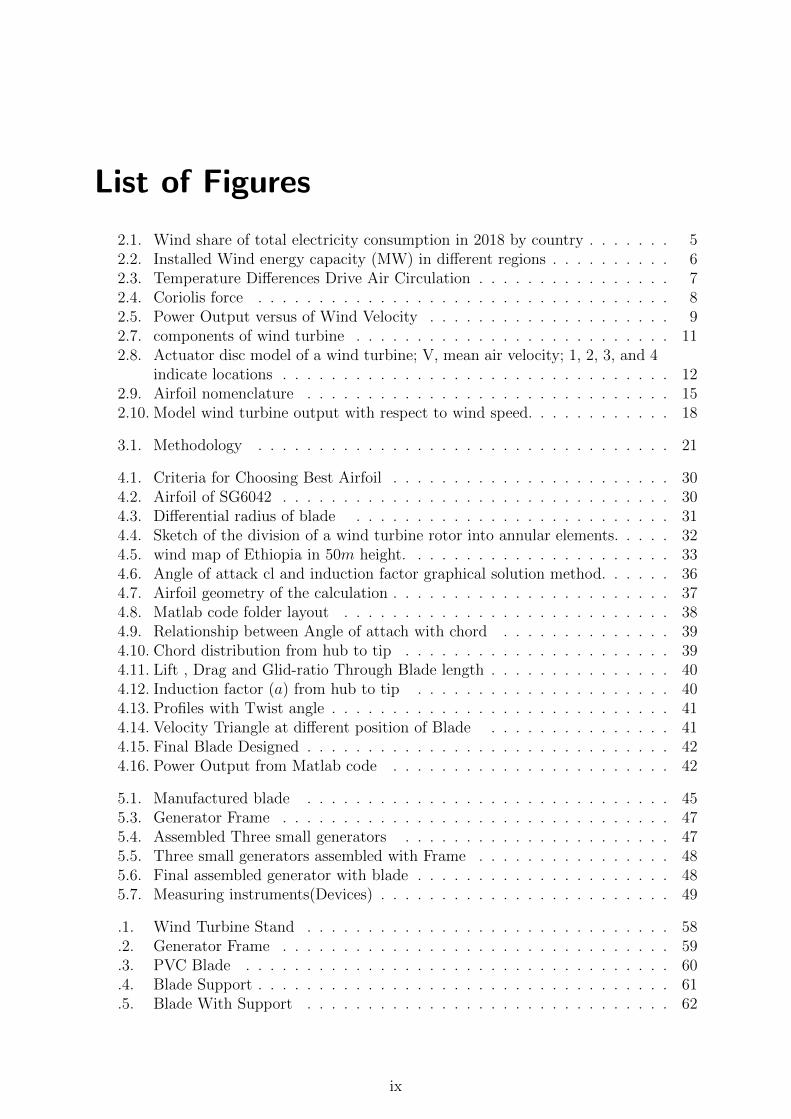
List of Figures
2.1. Wind share of total electricity consumption in 2018 by country . . . . . . . 52.2. Installed Wind energy capacity (MW) in different regions . . . . . . . . . . 62.3. Temperature Differences Drive Air Circulation . . . . . . . . . . . . . . . . 72.4. Coriolis force . . . . . . . . . . . . . . . . . . . . . . . . . . . . . . . . . . 82.5. Power Output versus of Wind Velocity . . . . . . . . . . . . . . . . . . . . 92.7. components of wind turbine . . . . . . . . . . . . . . . . . . . . . . . . . . 112.8. Actuator disc model of a wind turbine; V, mean air velocity; 1, 2, 3, and 4
indicate locations . . . . . . . . . . . . . . . . . . . . . . . . . . . . . . . . 122.9. Airfoil nomenclature . . . . . . . . . . . . . . . . . . . . . . . . . . . . . . 152.10. Model wind turbine output with respect to wind speed. . . . . . . . . . . . 18
3.1. Methodology . . . . . . . . . . . . . . . . . . . . . . . . . . . . . . . . . . 21
4.1. Criteria for Choosing Best Airfoil . . . . . . . . . . . . . . . . . . . . . . . 304.2. Airfoil of SG6042 . . . . . . . . . . . . . . . . . . . . . . . . . . . . . . . . 304.3. Differential radius of blade . . . . . . . . . . . . . . . . . . . . . . . . . . 314.4. Sketch of the division of a wind turbine rotor into annular elements. . . . . 324.5. wind map of Ethiopia in 50m height. . . . . . . . . . . . . . . . . . . . . . 334.6. Angle of attack cl and induction factor graphical solution method. . . . . . 364.7. Airfoil geometry of the calculation . . . . . . . . . . . . . . . . . . . . . . . 374.8. Matlab code folder layout . . . . . . . . . . . . . . . . . . . . . . . . . . . 384.9. Relationship between Angle of attach with chord . . . . . . . . . . . . . . 394.10. Chord distribution from hub to tip . . . . . . . . . . . . . . . . . . . . . . 394.11. Lift , Drag and Glid-ratio Through Blade length . . . . . . . . . . . . . . . 404.12. Induction factor (a) from hub to tip . . . . . . . . . . . . . . . . . . . . . 404.13. Profiles with Twist angle . . . . . . . . . . . . . . . . . . . . . . . . . . . . 414.14. Velocity Triangle at different position of Blade . . . . . . . . . . . . . . . 414.15. Final Blade Designed . . . . . . . . . . . . . . . . . . . . . . . . . . . . . . 424.16. Power Output from Matlab code . . . . . . . . . . . . . . . . . . . . . . . 42
5.1. Manufactured blade . . . . . . . . . . . . . . . . . . . . . . . . . . . . . . 455.3. Generator Frame . . . . . . . . . . . . . . . . . . . . . . . . . . . . . . . . 475.4. Assembled Three small generators . . . . . . . . . . . . . . . . . . . . . . 475.5. Three small generators assembled with Frame . . . . . . . . . . . . . . . . 485.6. Final assembled generator with blade . . . . . . . . . . . . . . . . . . . . . 485.7. Measuring instruments(Devices) . . . . . . . . . . . . . . . . . . . . . . . . 49
.1. Wind Turbine Stand . . . . . . . . . . . . . . . . . . . . . . . . . . . . . . 58
.2. Generator Frame . . . . . . . . . . . . . . . . . . . . . . . . . . . . . . . . 59
.3. PVC Blade . . . . . . . . . . . . . . . . . . . . . . . . . . . . . . . . . . . 60
.4. Blade Support . . . . . . . . . . . . . . . . . . . . . . . . . . . . . . . . . . 61
.5. Blade With Support . . . . . . . . . . . . . . . . . . . . . . . . . . . . . . 62
ix

.6. Final Assembled Wind Turbine . . . . . . . . . . . . . . . . . . . . . . . . 63
x
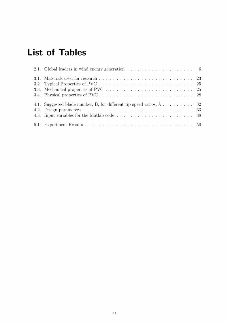
List of Tables
2.1. Global leaders in wind energy generation . . . . . . . . . . . . . . . . . . . 6
3.1. Materials used for research . . . . . . . . . . . . . . . . . . . . . . . . . . . 233.2. Typical Properties of PVC . . . . . . . . . . . . . . . . . . . . . . . . . . . 253.3. Mechanical properties of PVC . . . . . . . . . . . . . . . . . . . . . . . . . 253.4. Physical properties of PVC . . . . . . . . . . . . . . . . . . . . . . . . . . . 28
4.1. Suggested blade number, B, for different tip speed ratios, λ . . . . . . . . . 324.2. Design parameters . . . . . . . . . . . . . . . . . . . . . . . . . . . . . . . 334.3. Input variables for the Matlab code . . . . . . . . . . . . . . . . . . . . . . 38
5.1. Experiment Results . . . . . . . . . . . . . . . . . . . . . . . . . . . . . . . 50
xi
1. Introduction
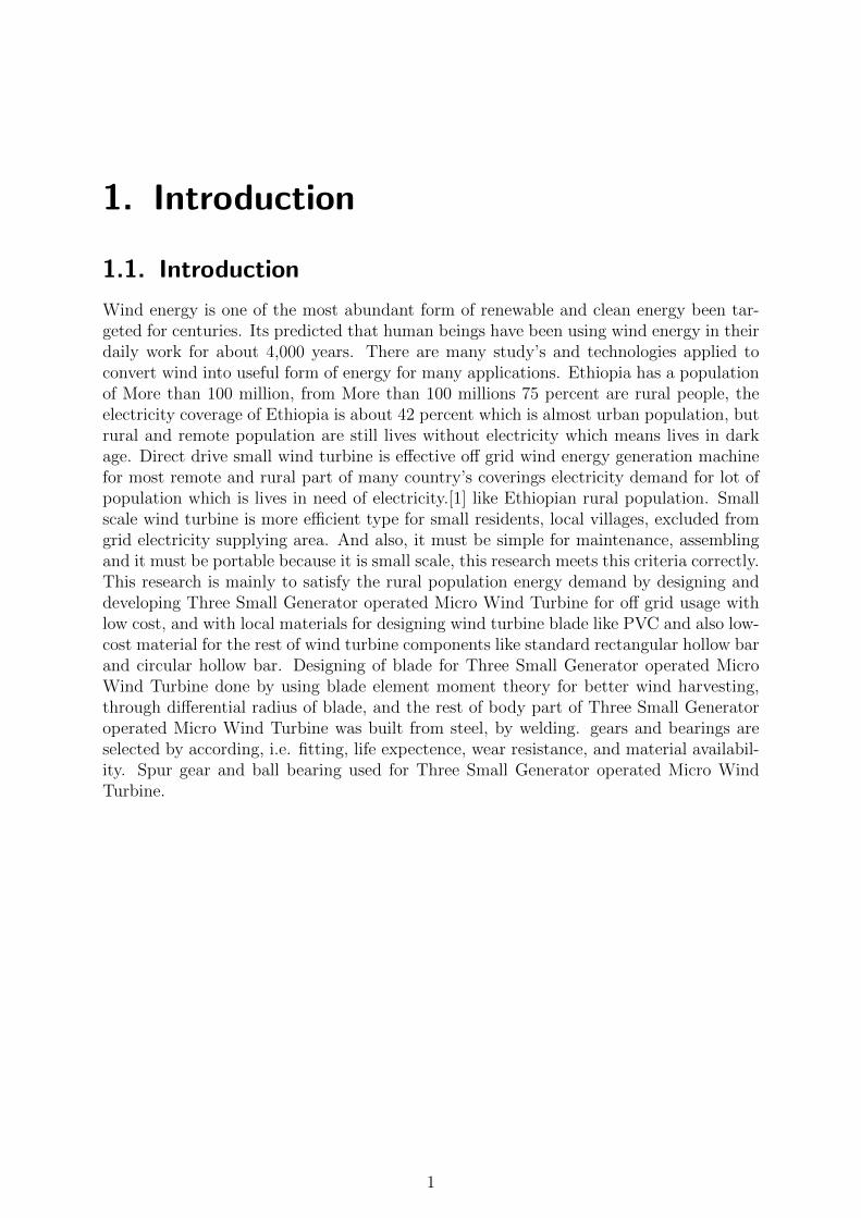
1.1. Introduction
Wind energy is one of the most abundant form of renewable and clean energy been tar-geted for centuries. Its predicted that human beings have been using wind energy in theirdaily work for about 4,000 years. There are many study’s and technologies applied toconvert wind into useful form of energy for many applications. Ethiopia has a populationof More than 100 million, from More than 100 millions 75 percent are rural people, theelectricity coverage of Ethiopia is about 42 percent which is almost urban population, butrural and remote population are still lives without electricity which means lives in darkage. Direct drive small wind turbine is effective off grid wind energy generation machinefor most remote and rural part of many country’s coverings electricity demand for lot ofpopulation which is lives in need of electricity.[1] like Ethiopian rural population. Smallscale wind turbine is more efficient type for small residents, local villages, excluded fromgrid electricity supplying area. And also, it must be simple for maintenance, assemblingand it must be portable because it is small scale, this research meets this criteria correctly.This research is mainly to satisfy the rural population energy demand by designing anddeveloping Three Small Generator operated Micro Wind Turbine for off grid usage withlow cost, and with local materials for designing wind turbine blade like PVC and also low-cost material for the rest of wind turbine components like standard rectangular hollow barand circular hollow bar. Designing of blade for Three Small Generator operated MicroWind Turbine done by using blade element moment theory for better wind harvesting,through differential radius of blade, and the rest of body part of Three Small Generatoroperated Micro Wind Turbine was built from steel, by welding. gears and bearings areselected by according, i.e. fitting, life expectence, wear resistance, and material availabil-ity. Spur gear and ball bearing used for Three Small Generator operated Micro WindTurbine.
1
Design And development of Three Small Generators operated Micro Wind Turbine
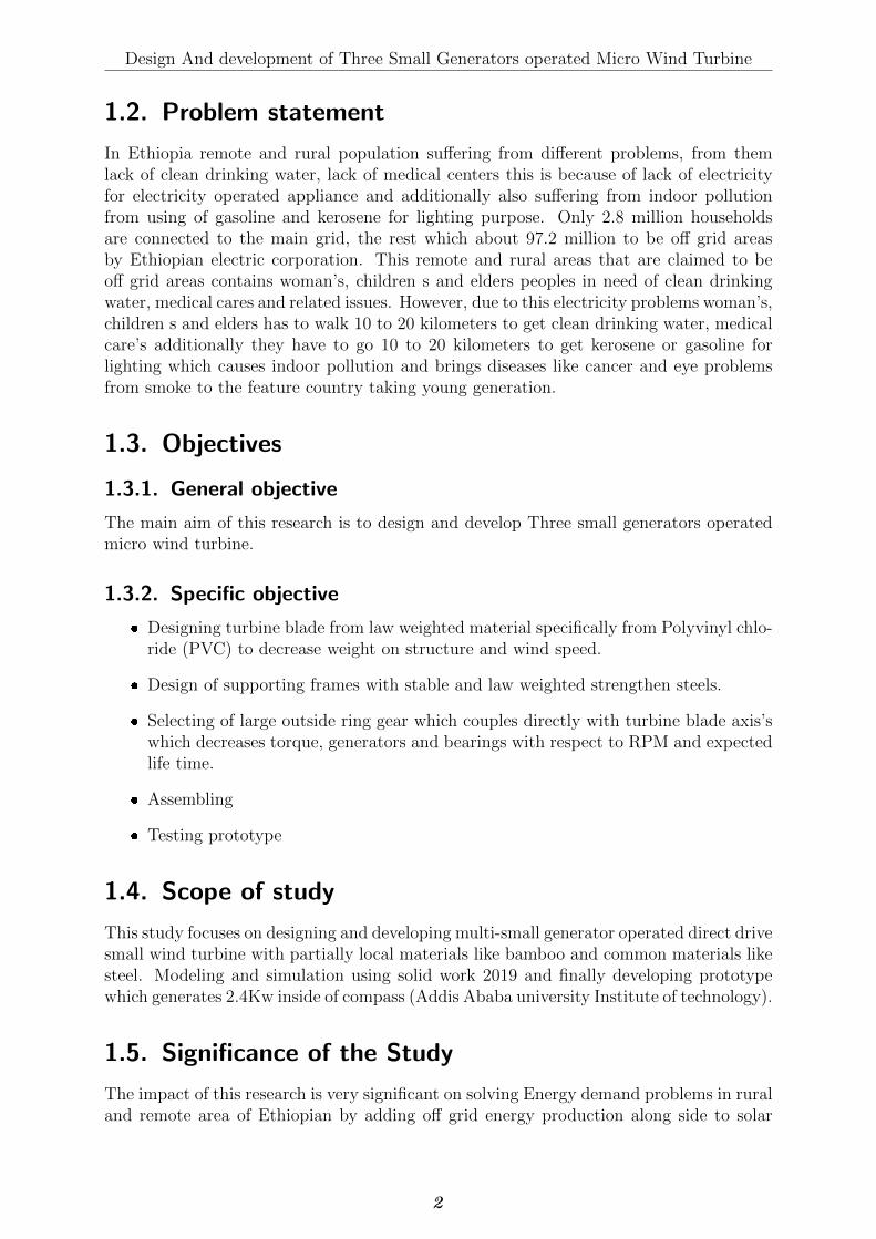
1.2. Problem statement
In Ethiopia remote and rural population suffering from different problems, from themlack of clean drinking water, lack of medical centers this is because of lack of electricityfor electricity operated appliance and additionally also suffering from indoor pollutionfrom using of gasoline and kerosene for lighting purpose. Only 2.8 million householdsare connected to the main grid, the rest which about 97.2 million to be off grid areasby Ethiopian electric corporation. This remote and rural areas that are claimed to beoff grid areas contains woman’s, children s and elders peoples in need of clean drinkingwater, medical cares and related issues. However, due to this electricity problems woman’s,children s and elders has to walk 10 to 20 kilometers to get clean drinking water, medicalcare’s additionally they have to go 10 to 20 kilometers to get kerosene or gasoline forlighting which causes indoor pollution and brings diseases like cancer and eye problemsfrom smoke to the feature country taking young generation.
1.3. Objectives
1.3.1. General objective
The main aim of this research is to design and develop Three small generators operatedmicro wind turbine.
1.3.2. Specific objective
� Designing turbine blade from law weighted material specifically from Polyvinyl chlo-ride (PVC) to decrease weight on structure and wind speed.
� Design of supporting frames with stable and law weighted strengthen steels.
� Selecting of large outside ring gear which couples directly with turbine blade axis’swhich decreases torque, generators and bearings with respect to RPM and expectedlife time.
� Assembling
� Testing prototype
1.4. Scope of study
This study focuses on designing and developing multi-small generator operated direct drivesmall wind turbine with partially local materials like bamboo and common materials likesteel. Modeling and simulation using solid work 2019 and finally developing prototypewhich generates 2.4Kw inside of compass (Addis Ababa university Institute of technology).
1.5. Significance of the Study
The impact of this research is very significant on solving Energy demand problems in ruraland remote area of Ethiopian by adding off grid energy production along side to solar
2

Design And development of Three Small Generators operated Micro Wind Turbine
panels. This research converts wind energy to mechanical,and mechanical to electricalenergy and it is easy to use and also easy configuration of structure for placing in every-where. It is applicable in average part of Ethiopia with average wind speed of 5.5m/s to6m/s. Therefore, the impact of this study is clearly higher in solving the power demandof off-grid system with a lower financial requirement. So, this may attract the attention ofmany researchers to go further in improving the efficiency Three small generator operatedDirect drive wind turbine. Additionally, reducing the hard currency expended for thepurchasing of material will reduce for same desired maximum power output compared tohydro and Pv system.
3
2. Literature Review
2.1. Wind Energy
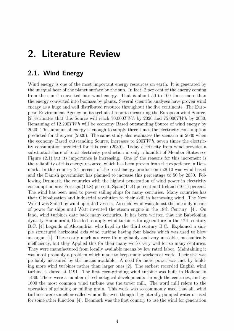
Wind energy is one of the most important energy resources on earth. It is generated bythe unequal heat of the planet surface by the sun. In fact, 2 per cent of the energy comingfrom the sun is converted into wind energy. That is about 50 to 100 times more thanthe energy converted into biomass by plants. Several scientific analyses have proven windenergy as a huge and well distributed resource throughout the five continents. The Euro-pean Environment Agency on its technical reports measuring the European wind Source.[2] estimates that this Source will reach 70.000TWh by 2020 and 75.000TWh by 2030,Remaining of 12.200TWh will be economy Based outstanding Source of wind energy by2020. This amount of energy is enough to supply three times the electricity consumptionpredicted for this year (2020). The same study also evaluates the scenario in 2030 whenthe economy Based outstanding Source, increases to 200TWh, seven times the electric-ity consumption predicted for this year (2030). Today electricity from wind provides asubstantial share of total electricity production in only a handful of Member States seeFigure (2.1).but its importance is increasing. One of the reasons for this increment isthe reliability of this energy resource, which has been proven from the experience in Den-mark. In this country 24 percent of the total energy production in2010 was wind-basedand the Danish government has planned to increase this percentage to 50 by 2030. Fol-lowing Denmark, the countries with the highest penetration of wind power in electricityconsumption are: Portugal(14.8) percent, Spain(14.4) percent and Ireland (10.1) percent.The wind has been used to power sailing ships for many centuries. Many countries hastheir Globalization and industrial revolution to their skill in harnessing wind. The NewWorld was Sailed by wind operated vessels. As such, wind was almost the one only meansof power for ships until Watt invented the steam engine in the 18th Century [4]. Onland, wind turbines date back many centuries. It has been written that the Babyloniandynasty Hammurabi, Decided to apply wind turbines for agriculture in the 17th centuryB.C. [4] Legends of Alexandria, who lived in the third century B.C., Explained a sim-ple structured horizontal axis wind turbine having four blades which was used to blowan organ [4]. These early machines were Unimaginably and very unstable, mechanicallyinefficiency, but they Applied this for their many works very well for so many centuries.They were manufactured from locally available means by low rated labor. Maintaining itwas most probably a problem which made to keep many workers at work. Their size wasprobably measured by the means available. A need for more power was met by build-ing more wind turbines rather than larger ones [2]. The earliest recorded English windturbine is dated at 1191. The first corn-grinding wind turbine was built in Holland in1439. There were a number of technological developments through the centuries, and by1600 the most common wind turbine was the tower mill. The word mill refers to theoperation of grinding or milling grain. This work was so commonly used that all, windturbines were somehow called windmills, even though they literally pumped water or usedfor some other function [4]. Denmark was the first country to use the wind for generation
4
Design And development of Three Small Generators operated Micro Wind Turbine
Figure 2.1.: Wind share of total electricity consumption in 2018 by country[3]
of electricity. The Danes were effectively applied a 11.5 R wind turbine in 1890 to produceelectricity. By 1910, several hundreds of units with producing electricity of 5 to 25 kWwere in Application in Denmark. [4]
2.2. Current Trends of wind Energy
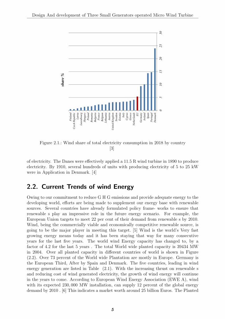
Owing to our commitment to reduce G H G emissions and provide adequate energy to thedeveloping world, efforts are being made to supplement our energy base with renewablesources. Several countries have already formulated policy frame- works to ensure thatrenewable s play an impressive role in the future energy scenario. For example, theEuropean Union targets to meet 22 per cent of their demand from renewable s by 2010.Wind, being the commercially viable and economically competitive renewable source, isgoing to be the major player in meeting this target. [5] Wind is the world’s Very fastgrowing energy means today and it has been staying that way for many consecutiveyears for the last five years. The world wind Energy capacity has changed to, by afactor of 4.2 for the last 5 years . The total World wide planted capacity is 39434 MWin 2004. Over all planted capacity in different countries of world is shown in Figure(2.2). Over 73 percent of the World wide Plantation are mostly in Europe. Germany isthe European Third, After by Spain and Denmark. The five countries, leading in windenergy generation are listed in Table (2.1). With the increasing thrust on renewable sand reducing cost of wind generated electricity, the growth of wind energy will continuein the years to come. According to European Wind Energy Association (EWE A), windwith its expected 230, 000 MW installation, can supply 12 percent of the global energydemand by 2010 . [6] This indicates a market worth around 25 billion Euros. The Planted
5
Design And development of Three Small Generators operated Micro Wind Turbine
capacity may got to a level of 1.2 million MW by 2020.
Table 2.1.: Global leaders in wind energy generation
Country’s Installed capacity in MWGermany 14609USA 6352Spain 6202Denmark 3115India 2120
[6]
Figure 2.2.: Installed Wind energy capacity (MW) in different regions[6]
2.3. Basics of wind energy conversion
Energy available in wind is basically the kinetic energy of large masses of air moving overthe earth’s surface.Blades of the wind turbine receive this kinetic energy, which is thentransformed to mechanical or electrical forms of energy, depending on the end use.
How wind Energy Formed
All renewable energy (except tidal and geothermal power), and even the energy in fossilfuels, all are originated from the sun. The sun radiates 100, 000, 000, 000, 000 KWh ofsolar energy to the earth per hour. In other words, the earth absorbs 10 to the 18thpower of watts of power. About 1 to 2 per cent of the energy comes from the sun isChanged into wind energy. That is about 50 to 100 times more than the energy Changedinto biomass, by all Flora on earth. [7]
(1) Temperature Differences, Drives Air Circulation
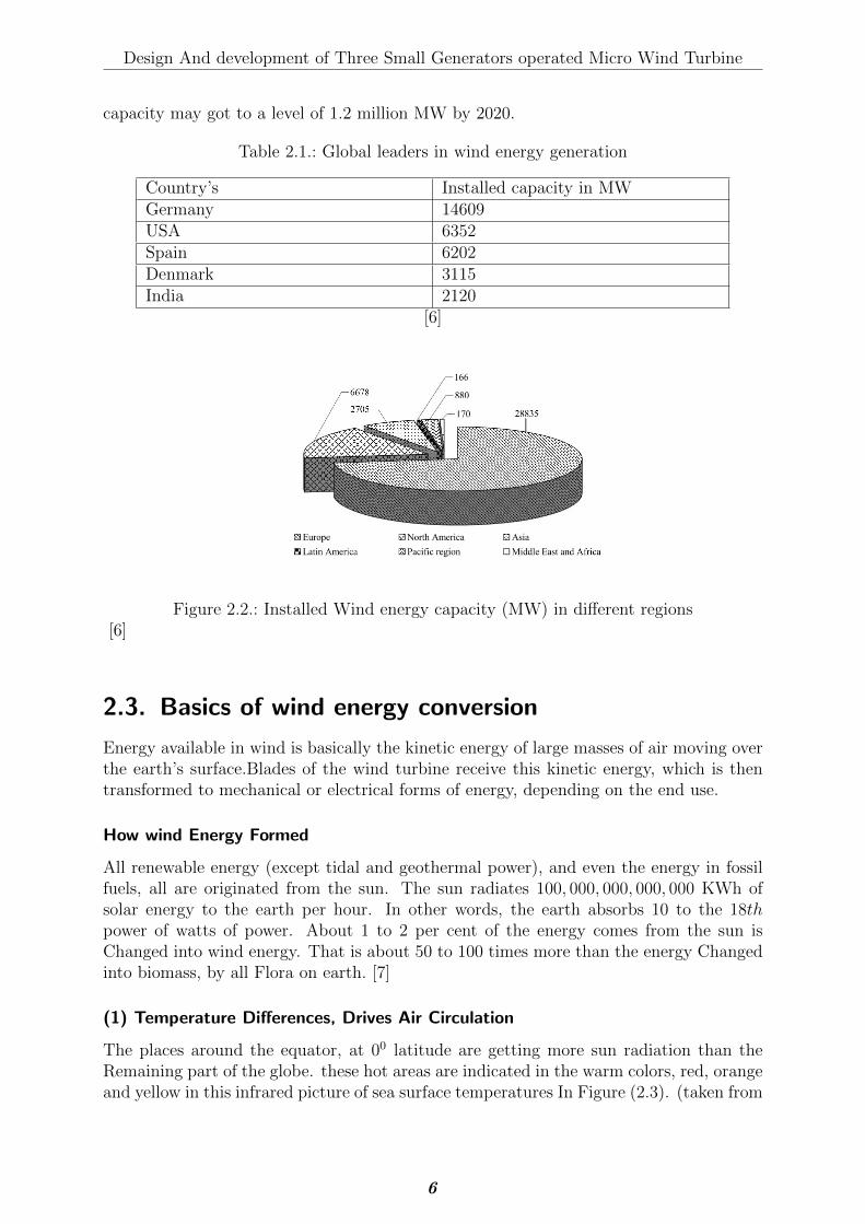
The places around the equator, at 00 latitude are getting more sun radiation than theRemaining part of the globe. these hot areas are indicated in the warm colors, red, orangeand yellow in this infrared picture of sea surface temperatures In Figure (2.3). (taken from
6
Design And development of Three Small Generators operated Micro Wind Turbine
Figure 2.3.: Temperature Differences Drive Air Circulation[4]
a NASA satellite, NOAA− 7inJuly1984).
Hot air is lighter than cold air and will rise into the sky until it reaches approximately10km(6miles) altitude and will spread to the North and the South. If the globe didn’trotate, the air would naturally Get at the North Pole and the South Pole, sank down,and get back to the equator.
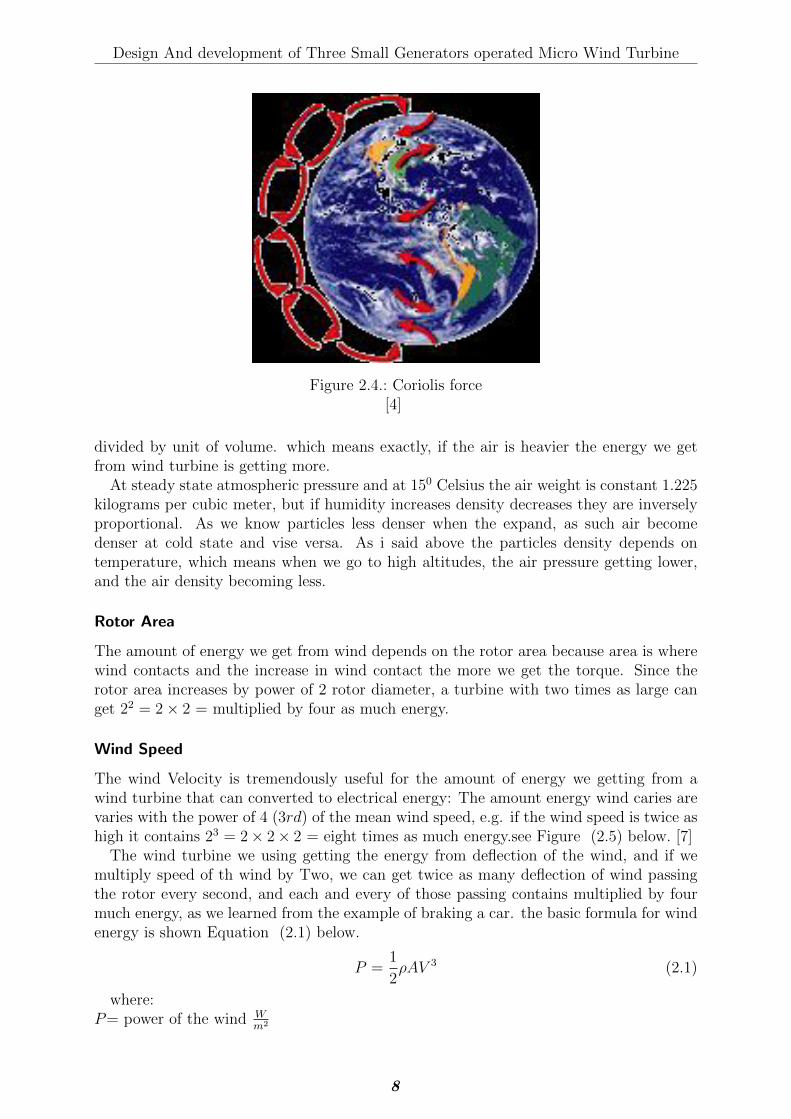
(2) The Coriolis Force
Since the globe is in orbital system and rotating, any motion linear or rotational on theNorthern hemisphere is return to the right, if we see at it from our own point of positionon the ground. (In the southern hemisphere it is resemble to the exact left). This causingof bending effect is called as the Coriolis force. (The name is given after French brilliantmathematician ”Gustave Gaspard Coriolis 1792-1843”).
The Coriolis force is a a force that can be seen in our daily bases. For example; Highwaytracks wear out faster on one side than the other.Most River beds are drill deeper on oneside than the other. (If you ask Which side it depends on which hemisphere we are inat: In the Northern hemisphere moving or flying objects are turn towards the right).In the Northern hemisphere the wind are tries to rotate counterclockwise (as we seen inabove) as it gets to a low pressure area.As such as in northern hemisphere In the Southernhemisphere the wind rotates clockwise, about low pressure areas. See Figure (2.4) below
2.3.1. Power in wind
As we know that A wind turbine gets its power input by converting the kinetic energy ofthe wind into a torque (turning force) Applied on the rotor blades. Density of the air isthe crucial for amount of energy which transfer to wind turbine blade, and also dependson the turbine blade area, and the wind Velocity.
Density of Air
The kinetic energy of a moving body is directly proportional to the mass (or weight).The kinetic energy in the wind are directly proportional to the air density, i.e. its mass
7
Design And development of Three Small Generators operated Micro Wind Turbine
Figure 2.4.: Coriolis force[4]
divided by unit of volume. which means exactly, if the air is heavier the energy we getfrom wind turbine is getting more.
At steady state atmospheric pressure and at 150 Celsius the air weight is constant 1.225kilograms per cubic meter, but if humidity increases density decreases they are inverselyproportional. As we know particles less denser when the expand, as such air becomedenser at cold state and vise versa. As i said above the particles density depends ontemperature, which means when we go to high altitudes, the air pressure getting lower,and the air density becoming less.
Rotor Area
The amount of energy we get from wind depends on the rotor area because area is wherewind contacts and the increase in wind contact the more we get the torque. Since therotor area increases by power of 2 rotor diameter, a turbine with two times as large canget 22 = 2× 2 = multiplied by four as much energy.
Wind Speed
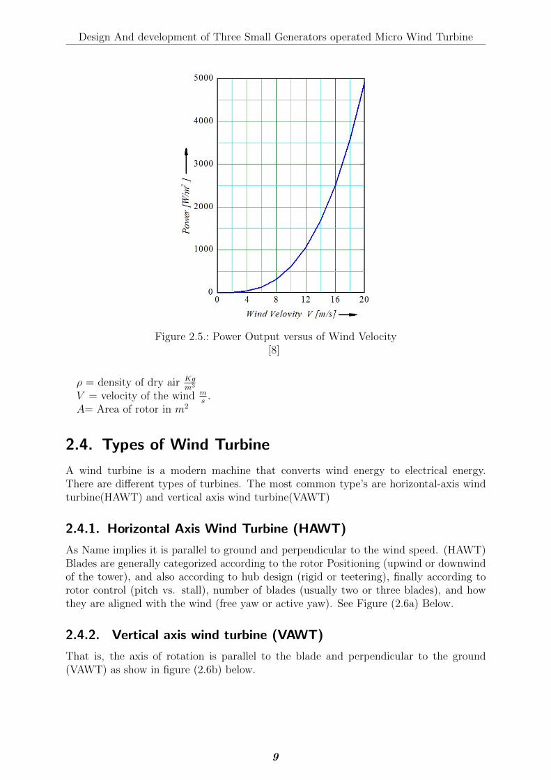
The wind Velocity is tremendously useful for the amount of energy we getting from awind turbine that can converted to electrical energy: The amount energy wind caries arevaries with the power of 4 (3rd) of the mean wind speed, e.g. if the wind speed is twice ashigh it contains 23 = 2× 2× 2 = eight times as much energy.see Figure (2.5) below. [7]
The wind turbine we using getting the energy from deflection of the wind, and if wemultiply speed of th wind by Two, we can get twice as many deflection of wind passingthe rotor every second, and each and every of those passing contains multiplied by fourmuch energy, as we learned from the example of braking a car. the basic formula for windenergy is shown Equation (2.1) below.
P =1
2ρAV 3 (2.1)
where:P= power of the wind W
m2
8
Design And development of Three Small Generators operated Micro Wind Turbine
Figure 2.5.: Power Output versus of Wind Velocity[8]
ρ = density of dry air Kgm3
V = velocity of the wind ms
.A= Area of rotor in m2
2.4. Types of Wind Turbine
A wind turbine is a modern machine that converts wind energy to electrical energy.There are different types of turbines. The most common type’s are horizontal-axis windturbine(HAWT) and vertical axis wind turbine(VAWT)
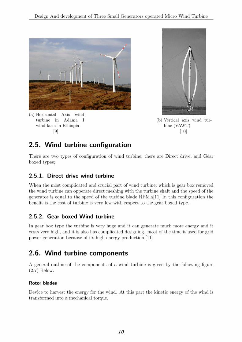
2.4.1. Horizontal Axis Wind Turbine (HAWT)
As Name implies it is parallel to ground and perpendicular to the wind speed. (HAWT)Blades are generally categorized according to the rotor Positioning (upwind or downwindof the tower), and also according to hub design (rigid or teetering), finally according torotor control (pitch vs. stall), number of blades (usually two or three blades), and howthey are aligned with the wind (free yaw or active yaw). See Figure (2.6a) Below.
2.4.2. Vertical axis wind turbine (VAWT)
That is, the axis of rotation is parallel to the blade and perpendicular to the ground(VAWT) as show in figure (2.6b) below.
9
Design And development of Three Small Generators operated Micro Wind Turbine
(a) Horizontal Axis windturbine in Adama Iwind-farm in Ethiopia
[9]
(b) Vertical axis wind tur-bine (VAWT)
[10]
2.5. Wind turbine configuration
There are two types of configuration of wind turbine; there are Direct drive, and Gearboxed types;
2.5.1. Direct drive wind turbine
When the most complicated and crucial part of wind turbine; which is gear box removedthe wind turbine can opperate direct meshing with the turbine shaft and the speed of thegenerator is equal to the speed of the turbine blade RPM.s[11] In this configuration thebenefit is the cost of turbine is very low with respect to the gear boxed type.
2.5.2. Gear boxed Wind turbine
In gear box type the turbine is very huge and it can generate much more energy and itcosts very high, and it is also has complicated designing. most of the time it used for gridpower generation because of its high energy production.[11]
2.6. Wind turbine components
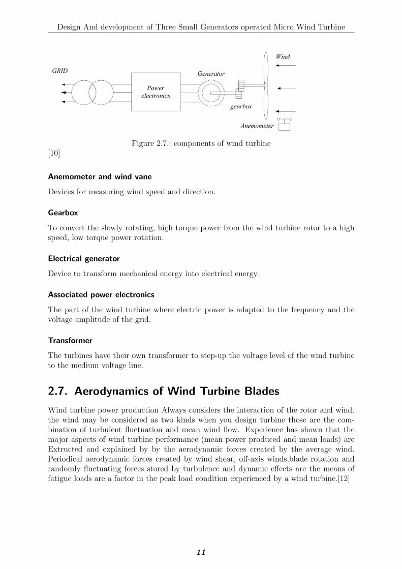
A general outline of the components of a wind turbine is given by the following figure(2.7) Below.
Rotor blades
Device to harvest the energy for the wind. At this part the kinetic energy of the wind istransformed into a mechanical torque.
10
Design And development of Three Small Generators operated Micro Wind Turbine
Figure 2.7.: components of wind turbine[10]
Anemometer and wind vane
Devices for measuring wind speed and direction.
Gearbox
To convert the slowly rotating, high torque power from the wind turbine rotor to a highspeed, low torque power rotation.
Electrical generator
Device to transform mechanical energy into electrical energy.
Associated power electronics
The part of the wind turbine where electric power is adapted to the frequency and thevoltage amplitude of the grid.
Transformer
The turbines have their own transformer to step-up the voltage level of the wind turbineto the medium voltage line.
2.7. Aerodynamics of Wind Turbine Blades
Wind turbine power production Always considers the interaction of the rotor and wind.the wind may be considered as two kinds when you design turbine those are the com-bination of turbulent fluctuation and mean wind flow. Experience has shown that themajor aspects of wind turbine performance (mean power produced and mean loads) areExtructed and explained by by the aerodynamic forces created by the average wind.Periodical aerodynamic forces created by wind shear, off-axis winds,blade rotation andrandomly fluctuating forces stored by turbulence and dynamic effects are the means offatigue loads are a factor in the peak load condition experienced by a wind turbine.[12]
11

Design And development of Three Small Generators operated Micro Wind Turbine
2.7.1. One-dimensional Momentum Theory and the Betz Limit
A Easy model, generally created to attribute Betz (1926), can be used to Find the powerfrom an ideal turbine blade, the thrust force of the wind on ideal blade, and the effect ofthe blade effect on the random location wind field. This Easy builtin model is based ona linear momentum theory derived over 100 years ago to estimate the efficiency of shippropellers. The analysis assumes a defined or boxed volume, in which the control volumeboundaries are the body of a stream tube and two cross-sectional surface of the streamtube (see Figure (2.8) ). The flow is one directional and its direction is across the endsof the stream tube surface. The turbine is Expected as a uniform ’actuator disc’ whichforms a discontinuity of pressure in the test tube of air flowing through it. Note: thatanalysis made in above are general analysis not to a specific wind turbine.
Figure 2.8.: Actuator disc model of a wind turbine; V, mean air velocity; 1, 2, 3, and 4indicate locations
[7]
12
Design And development of Three Small Generators operated Micro Wind Turbine
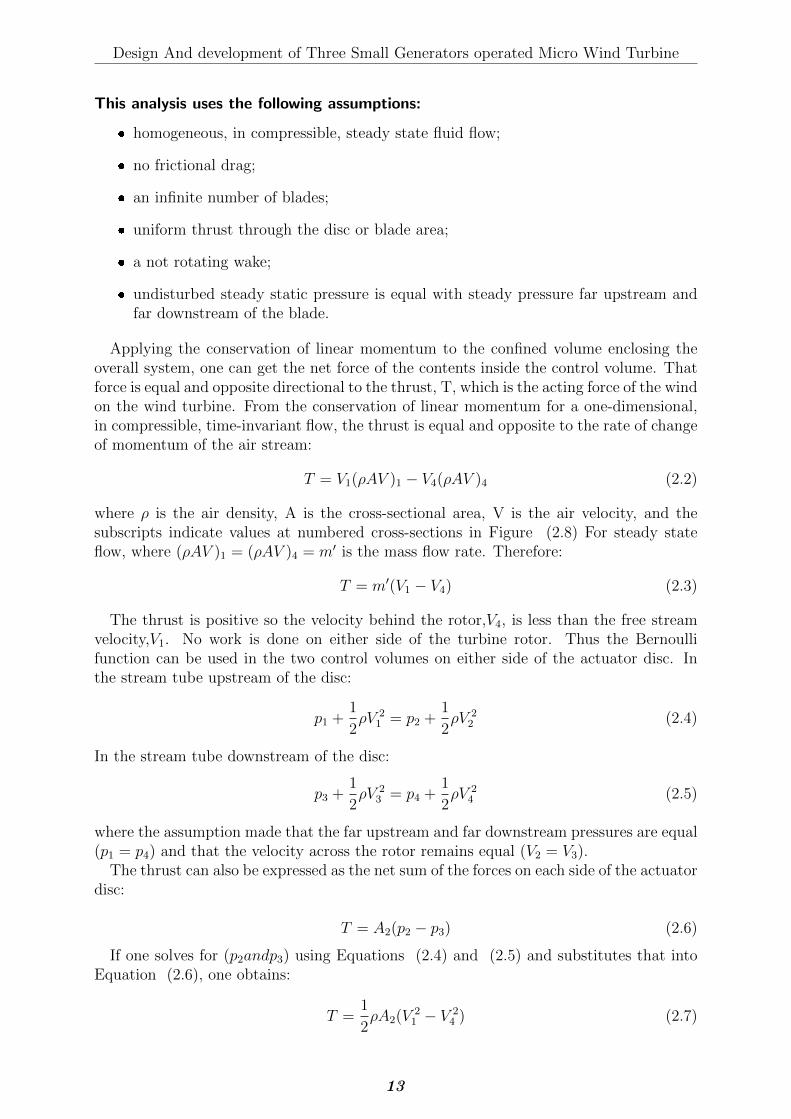
This analysis uses the following assumptions:
� homogeneous, in compressible, steady state fluid flow;
� no frictional drag;
� an infinite number of blades;
� uniform thrust through the disc or blade area;
� a not rotating wake;
� undisturbed steady static pressure is equal with steady pressure far upstream andfar downstream of the blade.
Applying the conservation of linear momentum to the confined volume enclosing theoverall system, one can get the net force of the contents inside the control volume. Thatforce is equal and opposite directional to the thrust, T, which is the acting force of the windon the wind turbine. From the conservation of linear momentum for a one-dimensional,in compressible, time-invariant flow, the thrust is equal and opposite to the rate of changeof momentum of the air stream:
T = V1(ρAV )1 − V4(ρAV )4 (2.2)
where ρ is the air density, A is the cross-sectional area, V is the air velocity, and thesubscripts indicate values at numbered cross-sections in Figure (2.8) For steady stateflow, where (ρAV )1 = (ρAV )4 = m′ is the mass flow rate. Therefore:
T = m′(V1 − V4) (2.3)
The thrust is positive so the velocity behind the rotor,V4, is less than the free streamvelocity,V1. No work is done on either side of the turbine rotor. Thus the Bernoullifunction can be used in the two control volumes on either side of the actuator disc. Inthe stream tube upstream of the disc:
p1 +1
2ρV 2
1 = p2 +1
2ρV 2
2 (2.4)
In the stream tube downstream of the disc:
p3 +1
2ρV 2
3 = p4 +1
2ρV 2
4 (2.5)
where the assumption made that the far upstream and far downstream pressures are equal(p1 = p4) and that the velocity across the rotor remains equal (V2 = V3).
The thrust can also be expressed as the net sum of the forces on each side of the actuatordisc:
T = A2(p2 − p3) (2.6)
If one solves for (p2andp3) using Equations (2.4) and (2.5) and substitutes that intoEquation (2.6), one obtains:
T =1
2ρA2(V
21 − V 2
4 ) (2.7)
13
Design And development of Three Small Generators operated Micro Wind Turbine
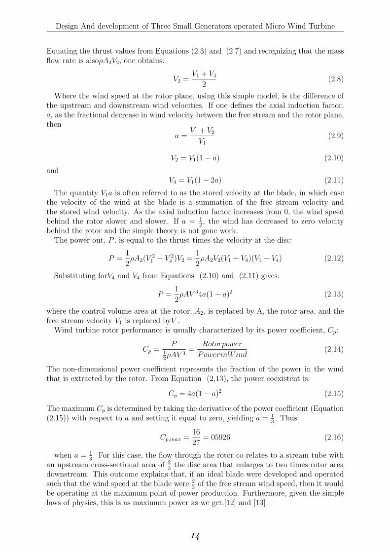
Equating the thrust values from Equations (2.3) and (2.7) and recognizing that the massflow rate is alsoρA2V2, one obtains:
V2 =V1 + V4
2(2.8)
Where the wind speed at the rotor plane, using this simple model, is the difference ofthe upstream and downstream wind velocities. If one defines the axial induction factor,a, as the fractional decrease in wind velocity between the free stream and the rotor plane,then
a =V1 + V2V1
(2.9)
V2 = V1(1− a) (2.10)
andV4 = V1(1− 2a) (2.11)
The quantity V1a is often referred to as the stored velocity at the blade, in which casethe velocity of the wind at the blade is a summation of the free stream velocity andthe stored wind velocity. As the axial induction factor increases from 0, the wind speedbehind the rotor slower and slower. If a = 1
2, the wind has decreased to zero velocity
behind the rotor and the simple theory is not gone work.The power out, P , is equal to the thrust times the velocity at the disc:
P =1
2ρA2(V
21 − V 2
4 )V2 =1
2ρA2V2(V1 + V4)(V1 − V4) (2.12)
Substituting forV4 and V4 from Equations (2.10) and (2.11) gives:
P =1
2ρAV 34a(1− a)2 (2.13)
where the control volume area at the rotor, A2, is replaced by A, the rotor area, and thefree stream velocity V1 is replaced byV .
Wind turbine rotor performance is usually characterized by its power coefficient, Cp:
Cp =P
12ρAV 3
=Rotorpower
PowerinWind(2.14)
The non-dimensional power coefficient represents the fraction of the power in the windthat is extracted by the rotor. From Equation (2.13), the power coexistent is:
Cp = 4a(1− a)2 (2.15)
The maximum Cp is determined by taking the derivative of the power coefficient (Equation(2.15)) with respect to a and setting it equal to zero, yielding a = 1
3. Thus:
Cp,max =16
27= 05926 (2.16)
when a = 13. For this case, the flow through the rotor co-relates to a stream tube with
an upstream cross-sectional area of 23
the disc area that enlarges to two times rotor areadownstream. This outcome explains that, if an ideal blade were developed and operatedsuch that the wind speed at the blade were 2
3of the free stream wind speed, then it would
be operating at the maximum point of power production. Furthermore, given the simplelaws of physics, this is as maximum power as we get.[12] and [13]
14

Design And development of Three Small Generators operated Micro Wind Turbine
2.7.2. Airfoils and General Concepts of Aerodynamics
Airfoils are structures with special geometry that given to them. the shape of airfoil areused to produce mechanical force due to the relative motion of the airfoil and a fluidthat surround the shape.Wind turbine blades use airfoils to develop mechanical power.The cross-sections of wind turbine blades have the shape of airfoils. The dimension ofthe blade are functions of the expected aerodynamic performance, the maximum ex-pected rotor power, the assumed airfoil properties, and strength of the airfoil take in toconsiderations.[12]
Airfoil Terminology
A number of terms are used to characterize an airfoil, as shown in Figure (2.9) The meancamber line is the locus of points halfway between the upper and lower surfaces of theairfoil. The most considered points of the mean camber line are on the leading and trailingedges,of the airfoil. the chord line is expressed as the line connecting the leading andtrailing edges of the airfoil, and the distance from point at edge of trialing and leading aredesignated as chord (c),of the airfoil. The camber is the distance between perpendicularchord line and the mean camber line. The thickness measured by the distance deferencebetween the upper and lower surface, perpendicular to chord line. Finally, the angle ofattack, α, is defined as the angle between the relative wind Vrel and the chord line.
Figure 2.9.: Airfoil nomenclature[1]
2.8. Materials for small wind turbine blade
The blades in a normally operating wind turbine rotor are continuously exposed to cyclicalloads from wind and gravity. The expected lifetime for a blade is usually 20 years for largewind turbines, and less than 20 years for small wind turbines (Clausen and Wood, 2000).Based on these requirements, [7] summarized that the primary condition to be takenin to account for blade materials are high stiffness to ensure aerodynamic performance,low density to minimize mass and long-fatigue cycles. Materials used in wind turbinetechnology are plastics, metals, wood, composite materials, this are the main materialsfrom the rest.[14] and [2]
15
Design And development of Three Small Generators operated Micro Wind Turbine
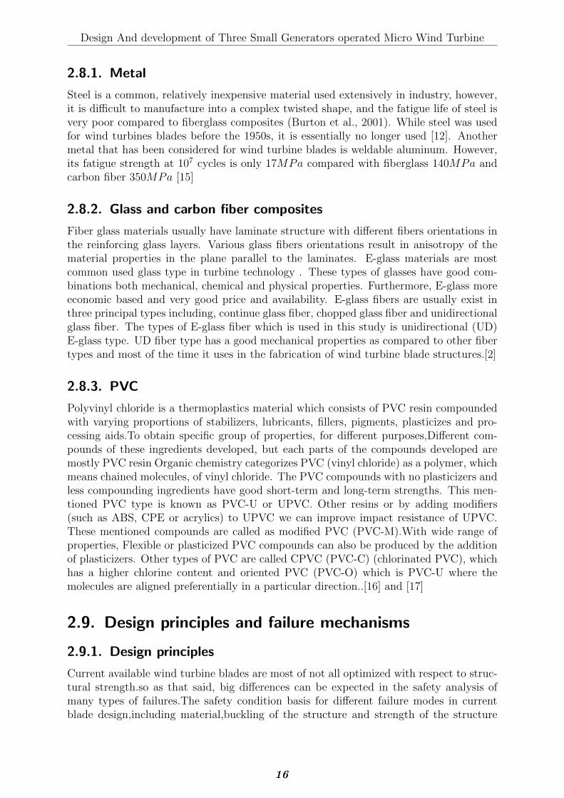
2.8.1. Metal
Steel is a common, relatively inexpensive material used extensively in industry, however,it is difficult to manufacture into a complex twisted shape, and the fatigue life of steel isvery poor compared to fiberglass composites (Burton et al., 2001). While steel was usedfor wind turbines blades before the 1950s, it is essentially no longer used [12]. Anothermetal that has been considered for wind turbine blades is weldable aluminum. However,its fatigue strength at 107 cycles is only 17MPa compared with fiberglass 140MPa andcarbon fiber 350MPa [15]
2.8.2. Glass and carbon fiber composites
Fiber glass materials usually have laminate structure with different fibers orientations inthe reinforcing glass layers. Various glass fibers orientations result in anisotropy of thematerial properties in the plane parallel to the laminates. E-glass materials are mostcommon used glass type in turbine technology . These types of glasses have good com-binations both mechanical, chemical and physical properties. Furthermore, E-glass moreeconomic based and very good price and availability. E-glass fibers are usually exist inthree principal types including, continue glass fiber, chopped glass fiber and unidirectionalglass fiber. The types of E-glass fiber which is used in this study is unidirectional (UD)E-glass type. UD fiber type has a good mechanical properties as compared to other fibertypes and most of the time it uses in the fabrication of wind turbine blade structures.[2]
2.8.3. PVC
Polyvinyl chloride is a thermoplastics material which consists of PVC resin compoundedwith varying proportions of stabilizers, lubricants, fillers, pigments, plasticizes and pro-cessing aids.To obtain specific group of properties, for different purposes,Different com-pounds of these ingredients developed, but each parts of the compounds developed aremostly PVC resin Organic chemistry categorizes PVC (vinyl chloride) as a polymer, whichmeans chained molecules, of vinyl chloride. The PVC compounds with no plasticizers andless compounding ingredients have good short-term and long-term strengths. This men-tioned PVC type is known as PVC-U or UPVC. Other resins or by adding modifiers(such as ABS, CPE or acrylics) to UPVC we can improve impact resistance of UPVC.These mentioned compounds are called as modified PVC (PVC-M).With wide range ofproperties, Flexible or plasticized PVC compounds can also be produced by the additionof plasticizers. Other types of PVC are called CPVC (PVC-C) (chlorinated PVC), whichhas a higher chlorine content and oriented PVC (PVC-O) which is PVC-U where themolecules are aligned preferentially in a particular direction..[16] and [17]
2.9. Design principles and failure mechanisms
2.9.1. Design principles
Current available wind turbine blades are most of not all optimized with respect to struc-tural strength.so as that said, big differences can be expected in the safety analysis ofmany types of failures.The safety condition basis for different failure modes in currentblade design,including material,buckling of the structure and strength of the structure
16
Design And development of Three Small Generators operated Micro Wind Turbine
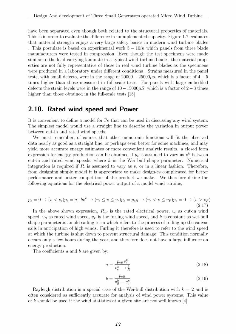
have been separated even though both related to the structural properties of materials.This is in order to evaluate the difference in unimplemented capacity. Figure 1.7 evaluatesthat material strength enjoys a very large safety basics in modern wind turbine blades. This postulate is based on experimental work 5 − 10in which panels from three blademanufacturers were tested in compression. Even though the test specimens were madesimilar to the load-carrying laminate in a typical wind turbine blade , the material prop-erties are not fully representative of those in real wind turbine blades as the specimenswere produced in a laboratory under different conditions . Strains measured in the paneltests, with small defects, were in the range of 20000− 25000µs, which is a factor of 4− 5times higher than those measured in full-scale tests. For panels with large embeddeddefects the strain levels were in the range of 10−15000µS, which is a factor of 2−3 timeshigher than those obtained in the full-scale tests.[18]
2.10. Rated wind speed and Power
It is convenient to define a model for Pe that can be used in discussing any wind system.The simplest model would use a straight line to describe the variation in output powerbetween cut-in and rated wind speeds.
We must remember, of course, that other monotonic functions will fit the observeddata nearly as good as a straight line, or perhaps even better for some machines, and mayyield more accurate energy estimates or more convenient analytic results. a closed formexpression for energy production can be obtained if pe is assumed to vary as vk betweencut-in and rated wind speeds, where k is the Wei bull shape parameter. Numericalintegration is required if Pe is assumed to vary as v, or in a linear fashion. Therefore,from designing simple model it is appropriate to make design-es complicated for betterperformance and better competition of the product we make.. We therefore define thefollowing equations for the electrical power output of a model wind turbine;
pe = 0→ (v < vc)pe = a+bvk → (vc ≤ v ≤ vr)pe = peR → (vr < v ≤ vF )pe = 0→ (v > vF )(2.17)
In the above shown expression, PeR is the rated electrical power, vc as cut-in windspeed, vR as rated wind speed, vF is the furling wind speed, and k is constant as wei-bullshape parameter.is an old sailing term which refers to the process of rolling up the canvassails in anticipation of high winds. Furling it therefore is used to refer to the wind speedat which the turbine is shut down to prevent structural damage. This condition normallyoccurs only a few hours during the year, and therefore does not have a large influence onenergy production.
The coefficients a and b are given by;
a =peRv
kc
vkc − vkR(2.18)
b =peR
vkR − vkc(2.19)
Rayleigh distribution is a special case of the Wei-bull distribution with k = 2 and isoften considered as sufficiently accurate for analysis of wind power systems. This valueof k should be used if the wind statistics at a given site are not well known.[4]
17
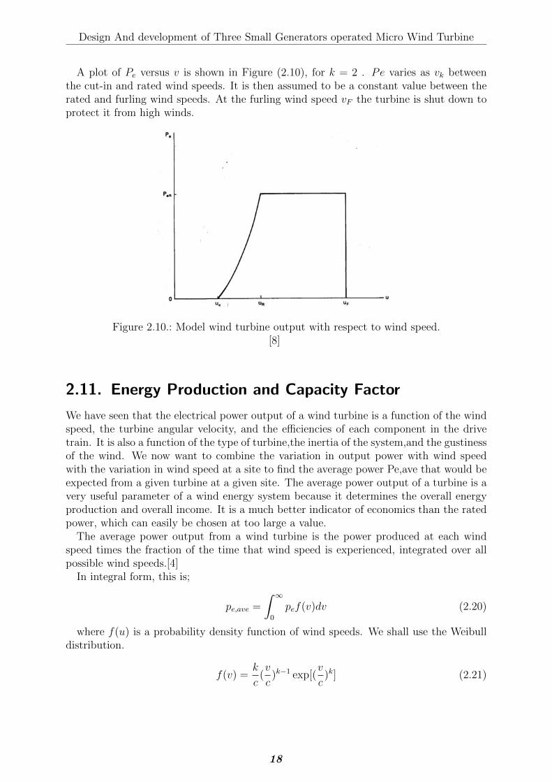
Design And development of Three Small Generators operated Micro Wind Turbine
A plot of Pe versus v is shown in Figure (2.10), for k = 2 . Pe varies as vk betweenthe cut-in and rated wind speeds. It is then assumed to be a constant value between therated and furling wind speeds. At the furling wind speed vF the turbine is shut down toprotect it from high winds.
Figure 2.10.: Model wind turbine output with respect to wind speed.[8]
2.11. Energy Production and Capacity Factor
We have seen that the electrical power output of a wind turbine is a function of the windspeed, the turbine angular velocity, and the efficiencies of each component in the drivetrain. It is also a function of the type of turbine,the inertia of the system,and the gustinessof the wind. We now want to combine the variation in output power with wind speedwith the variation in wind speed at a site to find the average power Pe,ave that would beexpected from a given turbine at a given site. The average power output of a turbine is avery useful parameter of a wind energy system because it determines the overall energyproduction and overall income. It is a much better indicator of economics than the ratedpower, which can easily be chosen at too large a value.
The average power output from a wind turbine is the power produced at each windspeed times the fraction of the time that wind speed is experienced, integrated over allpossible wind speeds.[4]
In integral form, this is;
pe,ave =
∫ ∞0
pef(v)dv (2.20)
where f(u) is a probability density function of wind speeds. We shall use the Weibulldistribution.
f(v) =k
c(v
c)k−1 exp[(
v
c)k] (2.21)
18
Design And development of Three Small Generators operated Micro Wind Turbine
Substituting Equation(2.17) and (2.21) into Equation (2.20) yields
pe,ave =
∫ vR
vc
(a+ bvk)f(v)dv + peR
∫ vF
vR
f(v)dv (2.22)
When we substitute the limits of integration into Equation (2.22), and reduce to theminimum number of terms, the result is;
pe,ave = peR{exp[−(vc
c)k]− exp[−(vR
c)k]
(vRc
)k − (vcc
)k− exp[−(
vFc
)k]} (2.23)
We can gain some insight into this design step by normalizing Equation (2.23). We firstobserve that the quantity inside the brackets of Eq. 30 is called the capacityfactor CF .Also called the plantfactor, it is an important design item in addition to the averagepower.
Finally we gate;
pe,ave = peR(CF ) = η1
2ρAv3R(CF ) (2.24)
When choosing rated wind speed we should not depend on the rated total efficiency,density of the air, or area of turbine rotor, because this mentioned quantity can be nor-malized. Also, since the capacity factor is expressed entirely in normalized wind speeds,it is convenient to do likewise in normalizing Equation (2.24) by dividing the expressionby c3 to get the term (vR/c)
3. We therefore define a normalized average power PN as;[4]
pN =pe,ave
η0(ρ2)Ac3
= (CF )(vRc
)3 (2.25)
2.12. Previous Works
According to Design Considerations of a Transverse Flux Machine for Direct-Drive WindTurbine Applications paper done by Tausif Husain and his associates,direct drive windturbine avoid disadvantage associated with gearing configuration, direct drive wind tur-bine designed with transverse flux, according to [19] direct drive wind turbine is optimizedwith transverse flux machine and they developed prototype which is more out put withless disadvantage from gear boxed type. The main consideration to design and developsmall direct drive wind turbine is start up torque, startup torque is the amount of forceneeded to rotate first round of blade which is very useful for any designer because thedesign must be work on low wind speed and should work anywhere as i mentioned to beoperate in low wind speed, which we can get anywhere according to paper Experimentalinvestigation of drive train resistance applied to small wind turbines, done by JoubersonL.R. Moreira and associates, [20] Startup torque reduction is key for small direct drivewind turbine. Direct drive wind turbine is always reliable for off grid uses according towind turbine manufacturer and it is cost effective, to transportation and maintenance itis very easy and handy, according to [11] this website direct drive wind turbine designingis very tricky because it has no yaw mechanism and it needs perfection. Wind speedrequired for small wind turbine to operate at optimum is average wind speed of 6.5m/swhich is no get everywhere around the globe because of wind speed fluctuation, and smalldirect drive wind turbine should be designed with law torque and low rpm generator.[21]Structure of wind turbine is very important for better load distribution and maintenance,on the article done bye Sethuraman, Latha and Fingersh, Lee J and Dykes, Katherine
19

Design And development of Three Small Generators operated Micro Wind Turbine
and Hayes, Austin they focused on structural part of direct drive small wind turbine,blade structure, generator structure specially because according to this paper, its veryessential part of wind turbine if it can be modified and can be driven by small amountof torque it can be operate at low wind speed, and can be operate average part of theglobe.[22] Direct drive wind turbine can also be grid grid used according to the paper doneby Mohamed Abbes,Jamel Belhadj , Afef Ben Abdelghani Bennani, by using a three-levelgrid side converter (GSC) direct drive wind turbine can also be used as grid type, thisis new concept and it is promising because direct drive is need much more RPM to pro-duce more energy, but that is can be solved by using (GSC) to step up and convert it togrid, and cover more places, which needs energy.[23] According to the paper Design studyof coated conductor direct drive wind turbine generator for small scale demonstration,coated conductor generator is promisingly good output for Mega watt stage direct drivewind turbine on this paper designed generator has high flux and can generate more powerin low rpm but it needed more torque, to start.[24]
20
3. Materials and Methodology
3.1. Methodology
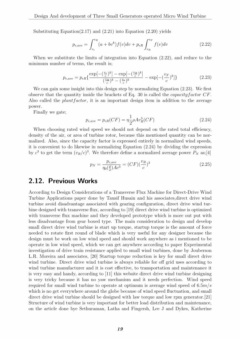
Graphical representation of methodology is expressed in detail below.
Figure 3.1.: Methodology
21

Design And development of Three Small Generators operated Micro Wind Turbine
3.1.1. Detail on methodology
Wind blade (rotor) design: -
In this task the followings are performed in detail one by one.
� Rotor sizing
� Choice of the numbers of blade.
� Choice of blade profile and materials.
� Determination of blade chord.
� Choice of pitch angle
� Load calculation:
– Blade loads.
– Rotor loads.
– Cods and standards.
– Design loads.
Designing of frames: -
Designing of frame on the basis of the following terms;
� Material selection based on the load types subjected to,
� Load calculation:
– Axial loads
– Tangential loads
– Bending moments
– Twisting moments (Torque)
3.1.2. Materials used for the research.
Materials used for research are shown in table below in Table 3.1
22
Design And development of Three Small Generators operated Micro Wind Turbine
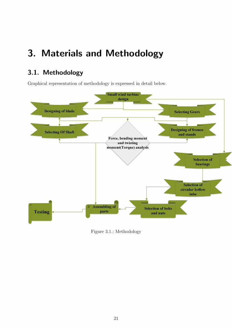
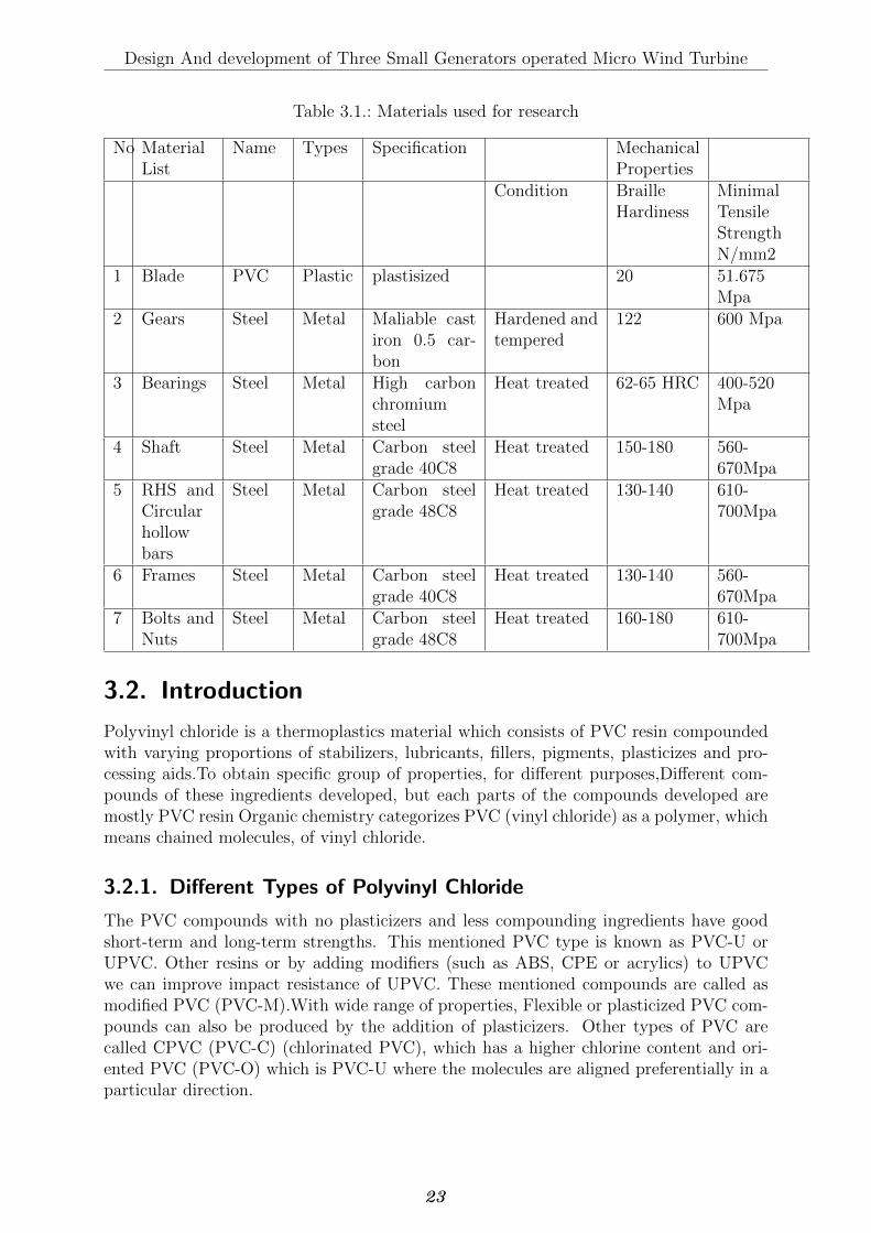
Table 3.1.: Materials used for research
No MaterialList
Name Types Specification MechanicalProperties
Condition BrailleHardiness
MinimalTensileStrengthN/mm2
1 Blade PVC Plastic plastisized 20 51.675Mpa
2 Gears Steel Metal Maliable castiron 0.5 car-bon
Hardened andtempered
122 600 Mpa
3 Bearings Steel Metal High carbonchromiumsteel
Heat treated 62-65 HRC 400-520Mpa
4 Shaft Steel Metal Carbon steelgrade 40C8
Heat treated 150-180 560-670Mpa
5 RHS andCircularhollowbars
Steel Metal Carbon steelgrade 48C8
Heat treated 130-140 610-700Mpa
6 Frames Steel Metal Carbon steelgrade 40C8
Heat treated 130-140 560-670Mpa
7 Bolts andNuts
Steel Metal Carbon steelgrade 48C8
Heat treated 160-180 610-700Mpa
3.2. Introduction
Polyvinyl chloride is a thermoplastics material which consists of PVC resin compoundedwith varying proportions of stabilizers, lubricants, fillers, pigments, plasticizes and pro-cessing aids.To obtain specific group of properties, for different purposes,Different com-pounds of these ingredients developed, but each parts of the compounds developed aremostly PVC resin Organic chemistry categorizes PVC (vinyl chloride) as a polymer, whichmeans chained molecules, of vinyl chloride.
3.2.1. Different Types of Polyvinyl Chloride
The PVC compounds with no plasticizers and less compounding ingredients have goodshort-term and long-term strengths. This mentioned PVC type is known as PVC-U orUPVC. Other resins or by adding modifiers (such as ABS, CPE or acrylics) to UPVCwe can improve impact resistance of UPVC. These mentioned compounds are called asmodified PVC (PVC-M).With wide range of properties, Flexible or plasticized PVC com-pounds can also be produced by the addition of plasticizers. Other types of PVC arecalled CPVC (PVC-C) (chlorinated PVC), which has a higher chlorine content and ori-ented PVC (PVC-O) which is PVC-U where the molecules are aligned preferentially in aparticular direction.
23
Design And development of Three Small Generators operated Micro Wind Turbine
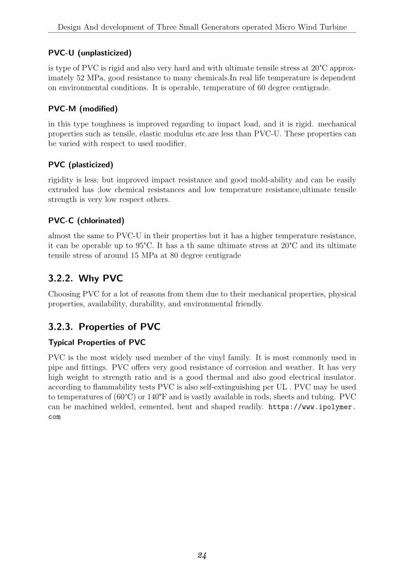
PVC-U (unplasticized)
is type of PVC is rigid and also very hard and with ultimate tensile stress at 20°C approx-imately 52 MPa, good resistance to many chemicals.In real life temperature is dependenton environmental conditions. It is operable, temperature of 60 degree centigrade.
PVC-M (modified)
in this type toughness is improved regarding to impact load, and it is rigid. mechanicalproperties such as tensile, elastic modulus etc.are less than PVC-U. These properties canbe varied with respect to used modifier.
PVC (plasticized)
rigidity is less; but improved impact resistance and good mold-ability and can be easilyextruded has ;low chemical resistances and low temperature resistance,ultimate tensilestrength is very low respect others.
PVC-C (chlorinated)
almost the same to PVC-U in their properties but it has a higher temperature resistance,it can be operable up to 95°C. It has a th same ultimate stress at 20°C and its ultimatetensile stress of around 15 MPa at 80 degree centigrade
3.2.2. Why PVC
Choosing PVC for a lot of reasons from them due to their mechanical properties, physicalproperties, availability, durability, and environmental friendly.
3.2.3. Properties of PVC
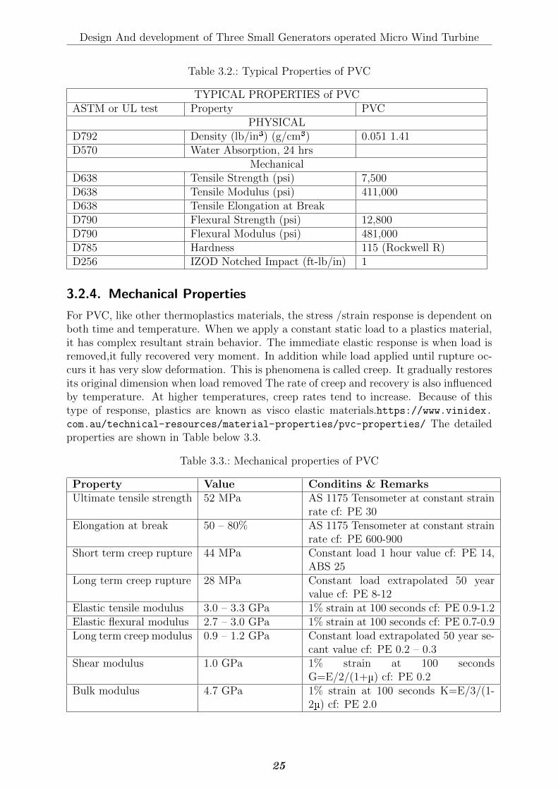
Typical Properties of PVC
PVC is the most widely used member of the vinyl family. It is most commonly used inpipe and fittings. PVC offers very good resistance of corrosion and weather. It has veryhigh weight to strength ratio and is a good thermal and also good electrical insulator.according to flammability tests PVC is also self-extinguishing per UL . PVC may be usedto temperatures of (60°C) or 140°F and is vastly available in rods, sheets and tubing. PVCcan be machined welded, cemented, bent and shaped readily. https://www.ipolymer.
com
24
Design And development of Three Small Generators operated Micro Wind Turbine
Table 3.2.: Typical Properties of PVC
TYPICAL PROPERTIES of PVCASTM or UL test Property PVC
PHYSICALD792 Density (lb/in³) (g/cm³) 0.051 1.41D570 Water Absorption, 24 hrs
MechanicalD638 Tensile Strength (psi) 7,500D638 Tensile Modulus (psi) 411,000D638 Tensile Elongation at BreakD790 Flexural Strength (psi) 12,800D790 Flexural Modulus (psi) 481,000D785 Hardness 115 (Rockwell R)D256 IZOD Notched Impact (ft-lb/in) 1
3.2.4. Mechanical Properties
For PVC, like other thermoplastics materials, the stress /strain response is dependent onboth time and temperature. When we apply a constant static load to a plastics material,it has complex resultant strain behavior. The immediate elastic response is when load isremoved,it fully recovered very moment. In addition while load applied until rupture oc-curs it has very slow deformation. This is phenomena is called creep. It gradually restoresits original dimension when load removed The rate of creep and recovery is also influencedby temperature. At higher temperatures, creep rates tend to increase. Because of thistype of response, plastics are known as visco elastic materials.https://www.vinidex.com.au/technical-resources/material-properties/pvc-properties/ The detailedproperties are shown in Table below 3.3.
Table 3.3.: Mechanical properties of PVC
Property Value Conditins & RemarksUltimate tensile strength 52 MPa AS 1175 Tensometer at constant strain
rate cf: PE 30Elongation at break 50 – 80% AS 1175 Tensometer at constant strain
rate cf: PE 600-900Short term creep rupture 44 MPa Constant load 1 hour value cf: PE 14,
ABS 25Long term creep rupture 28 MPa Constant load extrapolated 50 year
value cf: PE 8-12Elastic tensile modulus 3.0 – 3.3 GPa 1% strain at 100 seconds cf: PE 0.9-1.2Elastic flexural modulus 2.7 – 3.0 GPa 1% strain at 100 seconds cf: PE 0.7-0.9Long term creep modulus 0.9 – 1.2 GPa Constant load extrapolated 50 year se-
cant value cf: PE 0.2 – 0.3Shear modulus 1.0 GPa 1% strain at 100 seconds
G=E/2/(1+µ) cf: PE 0.2Bulk modulus 4.7 GPa 1% strain at 100 seconds K=E/3/(1-
2µ) cf: PE 2.0
25
Design And development of Three Small Generators operated Micro Wind Turbine
3.2.5. physical properties
physical properties of PVC is shown table below in detail data is teken from website calledhttps://www.vinidex.com.au/technical-resources/material-properties/pvc-properties/
general purpose plastics are; PVC, PE, PP and PS. The features of the particular plasticare determined by its chemical composition and type of molecular structure (molecularformation: crystalline/amorphous structure) PVC has an amorphous structure with po-lar chlorine atoms in the molecular structure. the amorphous molecular structure andchlorine atoms are inseparably related. apparently plastics resume very resembles in therelation of daily use, in terms of performance PVC has completely different functionsand features, With respect to olefin plastics which has only hydrogen and carbon atomsinside their molecular structures. Common feature among substances containing halo-gens is their Chemical stability from them chlorine and fluorine are mostly used. resinsPVC contains this mentioned substances, which more than that possess durability, fireretarding properties,chemical resistance and oil resistance.
Fire retarding properties
PVC has Naturally very high fire retarding properties because of its chlorine content,even if fire retardants are not added in to it. For example, PVC has 455°C of ignitiontemperature, and since it has not ignite easily, so the material has far less fire hazardrisk. moreover, the released heat from burning of PVC is considerably lower with respectto those for PP and PE. PVC therefore even while burning PVC contributes much lessto spreading fire to nearby materials, PVC is very suitable for safety reasons in productsclose to people’s daily lives.
Durability
Under normal conditions of use, the factor most strongly influencing the durability of amaterial is resistance to oxidation by atmospheric oxygen. PVC,where the chlorine atomis bound to every other carbon chain molecular structure, is high oxidative reactionsresistant, and can maintains its efficiency for a long time. Other general purpose plasticswith structures made up only of carbon and hydrogen are more susceptible to deteriorationby oxidation in extended use conditions (such as, for example, through repeated recycling).Measurements on underground 35 year-old PVC pipes taken by the Japan PVC Pipe& Fittings Association showed no deterioration and the same strength as new pipes.Researchers in Germany (60 Jahre Erfahrungen mit Rohrleitungen aus WeichmachfreiemPVC, 1995, KRV) Pipes buried in soil dug-ed up after 60 years and tested for fittingand life expense showed, it is perfectly fitted and it can effective for net 50 years touse anything. Almost there is no deterioration or degradation was seen upon restoreof three types of automobile exterior parts (using flexible PVC products plasticizers)cars after from about 13 years of use and upon compering physical properties with newproducts. Due to the heat time for thermal decomposition is Getting Shorter and shorter,in history the re-converting process, and by adding stabilizers it can be brought back tothe original products. Through re-converting,in fact Recovered products can recycled intothe same products, regardless of whether they are automobile parts or pipes. The physicalproperties of product recovered are the same as the original manufactured product fromvirgin resin or first produced, from resin in first place and also as good as first producedto use.
26
Design And development of Three Small Generators operated Micro Wind Turbine
Oil/Chemical resistance
PVC has best acid, alkali and almost all inorganic chemicals resistance.PVC Althoughcan swells or dissolves in and cyclic esters, aromatic hydrocarbons, ketones, PVC cn notdissolve in other organic solvents unless there is additional chemical applied. Because ofthis properties PVC can be used in many applications such for example,sheets used inconstruction, bottles,exhaust gas ducts,hoses and tubes.
Mechanical stability
PVC material is chemically stable, which shows very little structural change in molecularstructure, and also Expresses changes in its mechanical strength. However, long chainedpolymers are visco-elastic materials, and can be deformed by continuously applying ofexternal force, even if the force applied is much less than their yield point. This phenomenais known as creep deformation. However PVC is a visco-elastic material,but its creepdeformation is much lower compared to other plastics due to limited motion molecules attheir ordinary temperature, in compering to PP and PE,Their amorphous section havegreater molecular motion. Study on European very early pipes of PVC – Manufacturedfrom the 1930s to 1950s – showed characteristics of a excellent durability and service lifeof 50 year. More recent manufactured (latest) PVC pipes would be expected to have verylong lasting durability approximately about 100 years or exceed 100 years.
Processability and mouldability
The process ability of a thermoplastic material are largely affected on its melting viscos-ity. PVC is not applicable for injection molding of big or huge sized products, becauseof its high melt viscosity comparatively. On the other hand, the visco-elastic proper-ties of molten PVC is less affected on temperature and also more stable. Therefore,PVC is Applicable for complex shaped extrusion profiling (e.g., Household materials andcar accessories), as well as production of wide sheets and films (e.g., agricultural filmsand PVC leather). The exterior surfaces of PVC display excellent superior embossingperformance-giving it to a vast variety of surface treatments with textures ranging fromsurface rendering to the completely de-lustered suede. as we know PVC is an amorphousplastic with no phase transition, molded PVC products has high dimensional accuracy.PVC also exhibits excellent secondarily, fabrication, welding process-ability in bending ,high-frequency bonding, as well as on-site work ability and vacuum forming. Processesonly feasible with PVC and very good qualities of PVC paste resin processing are screenprinting, coating and slush molding. These mentioned processing methods are most ofthe time used in undercoating, flooring,automobile sealants and wall covering.
Other properties making PVC versatile
PVC has good element, polar groups (chlorine), and is amorphous, because of that it,mixes effectively with various other substances. Physical properties that required for endproducts (e.g.,elasticity, flexibility,prevention of microbial growth, impact resistance,fireretarding anti-fouling, anti-mist.) can be freely designed through formulation with plasti-cizers and various coloring agents, modifiers and additives . PVC is the only multi-purposeplastic that allows wide, free and seamless adjustment of the expected physical propertiesof products such as elasticity, flexibility, and impact resistance, by adding plasticizers,modifiers and additives. Hence the physical properties of end products are adjustable
27
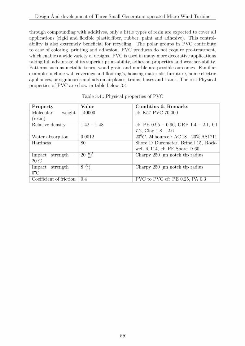
Design And development of Three Small Generators operated Micro Wind Turbine
through compounding with additives, only a little types of resin are expected to cover allapplications (rigid and flexible plastic,fiber, rubber, paint and adhesive). This control-ability is also extremely beneficial for recycling. The polar groups in PVC contributeto ease of coloring, printing and adhesion. PVC products do not require pre-treatment,which enables a wide variety of designs. PVC is used in many more decorative applicationstaking full advantage of its superior print-ability, adhesion properties and weather-ability.Patterns such as metallic tones, wood grain and marble are possible outcomes. Familiarexamples include wall coverings and flooring’s, housing materials, furniture, home electricappliances, or signboards and ads on airplanes, trains, buses and trams. The rest Physicalproperties of PVC are show in table below 3.4
Table 3.4.: Physical properties of PVC
Property Value Conditins & RemarksMolecular weight(resin)
140000 cf: K57 PVC 70,000
Relative density 1.42 – 1.48 cf: PE 0.95 – 0.96, GRP 1.4 – 2.1, CI7.2, Clay 1.8 – 2.6
Water absorption 0.0012 230C, 24 hours cf: AC 18 – 20% AS1711Hardness 80 Shore D Durometer, Brinell 15, Rock-
well R 114, cf: PE Shore D 60Impact strength –20°C
20 KJm2 Charpy 250 µm notch tip radius
Impact strength –0°C
8 KJm2 Charpy 250 µm notch tip radius
Coefficient of friction 0.4 PVC to PVC cf: PE 0.25, PA 0.3
28
4. Technical Design
4.1. Introduction
4.1.1. Wind Turbine Blade Material
The complexity of external loads on rotor blades lies in the fact that these loads cannotbe adequately modeled. Building a wind turbine blade is not simple a task, however, itrequires accomplishing certain benchmarks. Wind turbine blade materials need to have astrict property requirement of high stiffness, low weight, and long fatigue life. [25][4][12]
� High modulus of rigidity – to maintain optimal aerodynamic performance
� Low density – to reduce gravitational forces,
� Long-fatigue life – to reduce material failure.
4.2. PVC (Polyvinyl chloride)
4.2.1. Introduction
PVC is the most wide range applied member of the vinyl family. from various mostcommonly it is used in fittings and pipe. PVC has its special characters such as excellentcorrosion and weather resistance. It has a high weight to strength ratio and is a goodthermal and electrical and insulator. PVC is also self-extinguishing per UL flammabilitytests. PVC may be used to temperatures of 140F (60C) and is readily available in sheets,rods, and tubing. PVC may be cemented, welded, machined, bent and shaped readily.
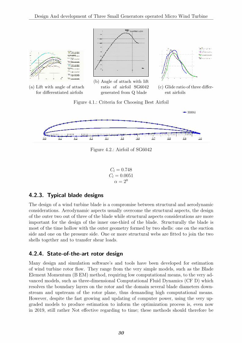
4.2.2. Choosing Best Aero-foil for the design
Thus, wind turbine thrust and power depend upon the lift and drag coefficients, Cl andCd respectively, of the airfoils sections that comprise each blade. For a great many airfoils,these coefficients are known from wind tunnel investigations, and, at least in principle,can be used immediately for power and thrust calculations. From available and testedairfoils we choose for small wind turbine blade with the help of Q-blade software http:
//q-blade.org
From the Q blade analysis we choose the best airfoil with the respect of Glids ratiowhich means the largest ratio of Cd to Cl.
For selection of the lift coefficient and designing angle of attach the ratio of must beminimum.From above polar data from Q-Blade analysis of airfoil the minimum is0.006811 .Corresponding lift coefficient (Cl) , drag coefficient (Cd) and angle of attach (α) are;The chosen aero-foil from above analysis is; SG6042
29
Design And development of Three Small Generators operated Micro Wind Turbine
(a) Lift with angle of attachfor differentiated airfoils
(b) Angle of attach with liftratio of airfoil SG6042generated from Q blade
(c) Glide ratio of three differ-ent airfoils
Figure 4.1.: Criteria for Choosing Best Airfoil
Figure 4.2.: Airfoil of SG6042
Cl = 0.748Cl = 0.0051α = 20
4.2.3. Typical blade designs
The design of a wind turbine blade is a compromise between structural and aerodynamicconsiderations. Aerodynamic aspects usually overcome the structural aspects, the designof the outer two out of three of the blade while structural aspects considerations are moreimportant for the design of the inner one-third of the blade. Structurally the blade ismost of the time hollow with the outer geometry formed by two shells: one on the suctionside and one on the pressure side. One or more structural webs are fitted to join the twoshells together and to transfer shear loads.
4.2.4. State-of-the-art rotor design
Many design and simulation software’s and tools have been developed for estimationof wind turbine rotor flow. They range from the very simple models, such as the BladeElement Momentum (B EM) method, requiring low computational means, to the very ad-vanced models, such as three-dimensional Computational Fluid Dynamics (CF D) whichresolves the boundary layers on the rotor and the domain several blade diameters down-stream and upstream of the rotor plane, thus demanding high computational means.However, despite the fast growing and updating of computer power, using the very up-graded models to produce estimation to inform the optimization process is, even nowin 2019, still rather Not effective regarding to time; these methods should therefore be
30
Design And development of Three Small Generators operated Micro Wind Turbine
considered as tools for evaluating the turbine blade design, rather than as part of theinherently iterative turbine blade design process.
4.2.5. The blade element momentum (BEM) method
The B EM method was developed in the 1930s, and since then other, but not very different,formulations have been developed. In what follows, the B EM method will be Explained,starting with a simplest and easy model which assumes that the Flow through the bladeacts the same way at all points which makes the problem one-dimensional. Furthermore,the assumption in the one-dimensional problem is that the rotor has no losses such asfriction caused by the air viscosity and no losses caused by the Flow at the tips.[26][27]The description of the simplified one-dimensional model is followed by a description ofthe more advanced B EM model, which uses the one-dimensional model in each annularelement and also takes these types of losses into account.
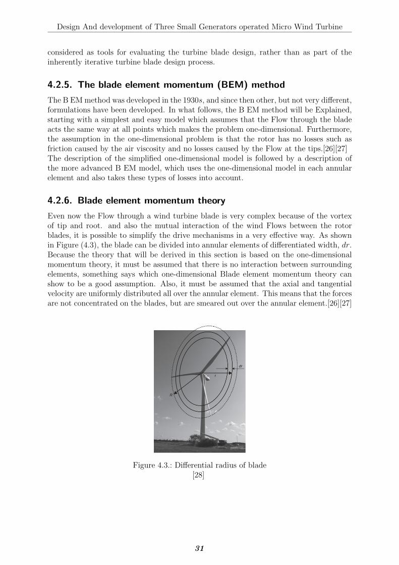
4.2.6. Blade element momentum theory
Even now the Flow through a wind turbine blade is very complex because of the vortexof tip and root. and also the mutual interaction of the wind Flows between the rotorblades, it is possible to simplify the drive mechanisms in a very effective way. As shownin Figure (4.3), the blade can be divided into annular elements of differentiated width, dr.Because the theory that will be derived in this section is based on the one-dimensionalmomentum theory, it must be assumed that there is no interaction between surroundingelements, something says which one-dimensional Blade element momentum theory canshow to be a good assumption. Also, it must be assumed that the axial and tangentialvelocity are uniformly distributed all over the annular element. This means that the forcesare not concentrated on the blades, but are smeared out over the annular element.[26][27]
Figure 4.3.: Differential radius of blade[28]
31
Design And development of Three Small Generators operated Micro Wind Turbine
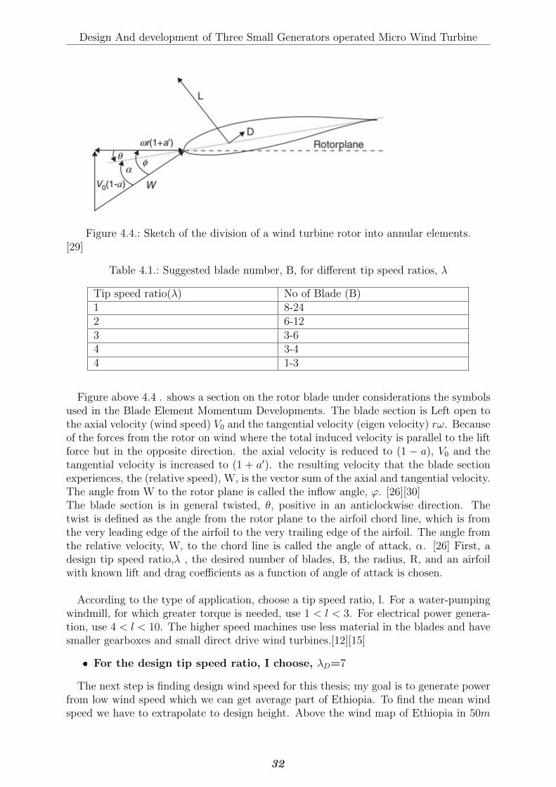
Figure 4.4.: Sketch of the division of a wind turbine rotor into annular elements.[29]
Table 4.1.: Suggested blade number, B, for different tip speed ratios, λ
Tip speed ratio(λ) No of Blade (B)1 8-242 6-123 3-64 3-44 1-3
Figure above 4.4 . shows a section on the rotor blade under considerations the symbolsused in the Blade Element Momentum Developments. The blade section is Left open tothe axial velocity (wind speed) V0 and the tangential velocity (eigen velocity) rω. Becauseof the forces from the rotor on wind where the total induced velocity is parallel to the liftforce but in the opposite direction. the axial velocity is reduced to (1 − a), V0 and thetangential velocity is increased to (1 + a′). the resulting velocity that the blade sectionexperiences, the (relative speed), W, is the vector sum of the axial and tangential velocity.The angle from W to the rotor plane is called the inflow angle, ϕ. [26][30]The blade section is in general twisted, θ, positive in an anticlockwise direction. Thetwist is defined as the angle from the rotor plane to the airfoil chord line, which is fromthe very leading edge of the airfoil to the very trailing edge of the airfoil. The angle fromthe relative velocity, W, to the chord line is called the angle of attack, α. [26] First, adesign tip speed ratio,λ , the desired number of blades, B, the radius, R, and an airfoilwith known lift and drag coefficients as a function of angle of attack is chosen.
According to the type of application, choose a tip speed ratio, l. For a water-pumpingwindmill, for which greater torque is needed, use 1 < l < 3. For electrical power genera-tion, use 4 < l < 10. The higher speed machines use less material in the blades and havesmaller gearboxes and small direct drive wind turbines.[12][15]
� For the design tip speed ratio, I choose, λD=7
The next step is finding design wind speed for this thesis; my goal is to generate powerfrom low wind speed which we can get average part of Ethiopia. To find the mean windspeed we have to extrapolate to design height. Above the wind map of Ethiopia in 50m
32
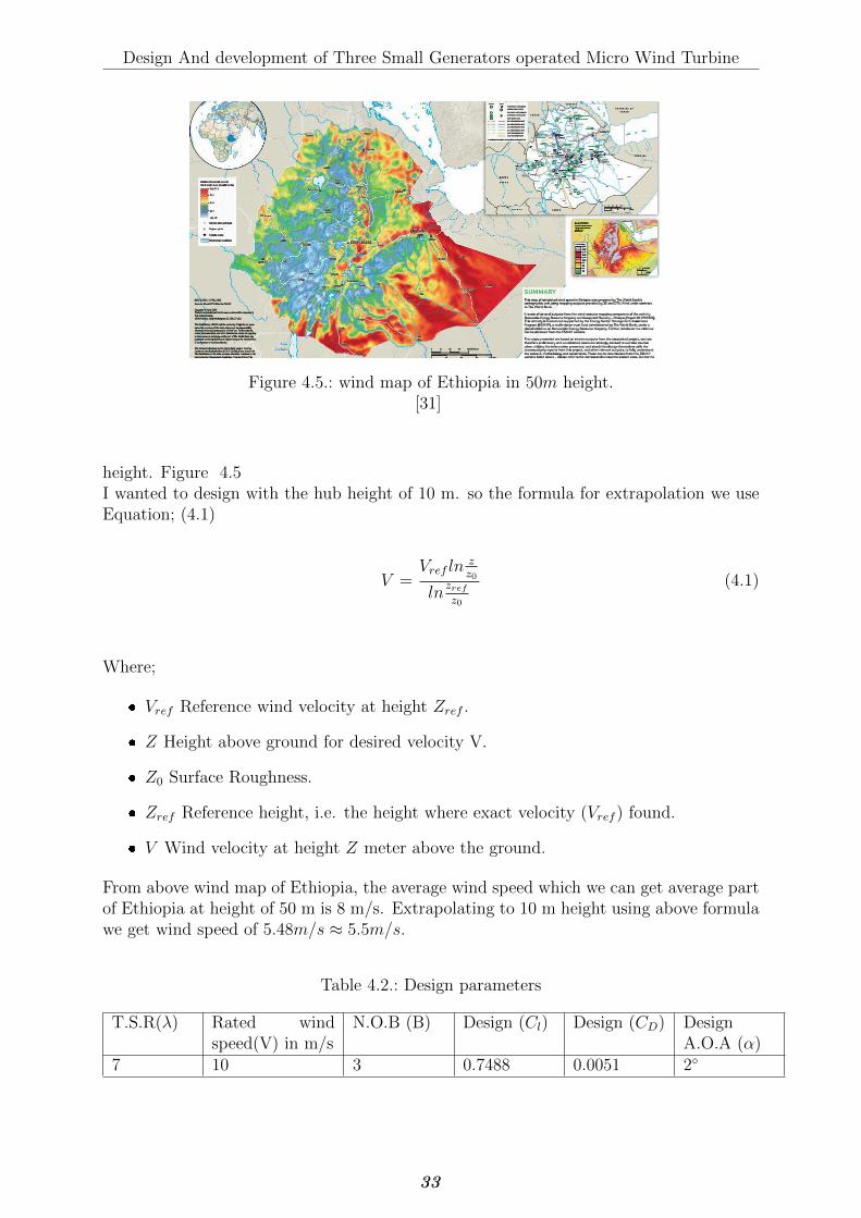
Design And development of Three Small Generators operated Micro Wind Turbine
Figure 4.5.: wind map of Ethiopia in 50m height.[31]
height. Figure 4.5I wanted to design with the hub height of 10 m. so the formula for extrapolation we useEquation; (4.1)
V =Vref ln
zz0
lnzrefz0
(4.1)
Where;
� Vref Reference wind velocity at height Zref .
� Z Height above ground for desired velocity V.
� Z0 Surface Roughness.
� Zref Reference height, i.e. the height where exact velocity (Vref ) found.
� V Wind velocity at height Z meter above the ground.
From above wind map of Ethiopia, the average wind speed which we can get average partof Ethiopia at height of 50 m is 8 m/s. Extrapolating to 10 m height using above formulawe get wind speed of 5.48m/s ≈ 5.5m/s.
Table 4.2.: Design parameters
T.S.R(λ) Rated windspeed(V) in m/s
N.O.B (B) Design (Cl) Design (CD) DesignA.O.A (α)
7 10 3 0.7488 0.0051 2◦
33
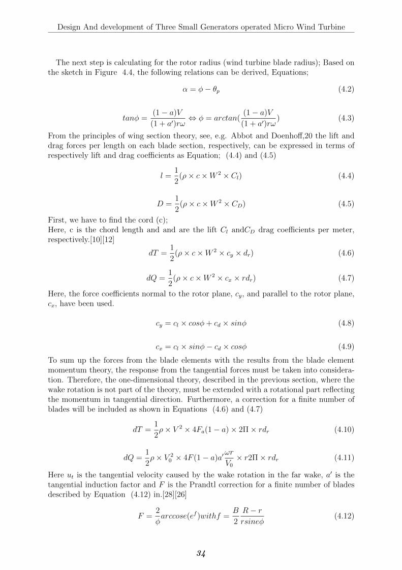
Design And development of Three Small Generators operated Micro Wind Turbine
The next step is calculating for the rotor radius (wind turbine blade radius); Based onthe sketch in Figure 4.4, the following relations can be derived, Equations;
α = φ− θp (4.2)
tanφ =(1− a)V
(1 + a′)rω⇔ φ = arctan(
(1− a)V
(1 + a′)rω) (4.3)
From the principles of wing section theory, see, e.g. Abbot and Doenhoff,20 the lift anddrag forces per length on each blade section, respectively, can be expressed in terms ofrespectively lift and drag coefficients as Equation; (4.4) and (4.5)
l =1
2(ρ× c×W 2 × Cl) (4.4)
D =1
2(ρ× c×W 2 × CD) (4.5)
First, we have to find the cord (c);Here, c is the chord length and and are the lift Cl andCD drag coefficients per meter,respectively.[10][12]
dT =1
2(ρ× c×W 2 × cy × dr) (4.6)
dQ =1
2(ρ× c×W 2 × cx × rdr) (4.7)
Here, the force coefficients normal to the rotor plane, cy, and parallel to the rotor plane,cx, have been used.
cy = cl × cosφ+ cd × sinφ (4.8)
cx = cl × sinφ− cd × cosφ (4.9)
To sum up the forces from the blade elements with the results from the blade elementmomentum theory, the response from the tangential forces must be taken into considera-tion. Therefore, the one-dimensional theory, described in the previous section, where thewake rotation is not part of the theory, must be extended with a rotational part reflectingthe momentum in tangential direction. Furthermore, a correction for a finite number ofblades will be included as shown in Equations (4.6) and (4.7)
dT =1
2ρ× V 2 × 4Fa(1− a)× 2Π× rdr (4.10)
dQ =1
2ρ× V 2
0 × 4F (1− a)a′ωr
V0× r2Π× rdr (4.11)
Here ut is the tangential velocity caused by the wake rotation in the far wake, a′ is thetangential induction factor and F is the Prandtl correction for a finite number of bladesdescribed by Equation (4.12) in.[28][26]
F =2
φarccose(ef )withf =
B
2
R− rrsineφ
(4.12)
34
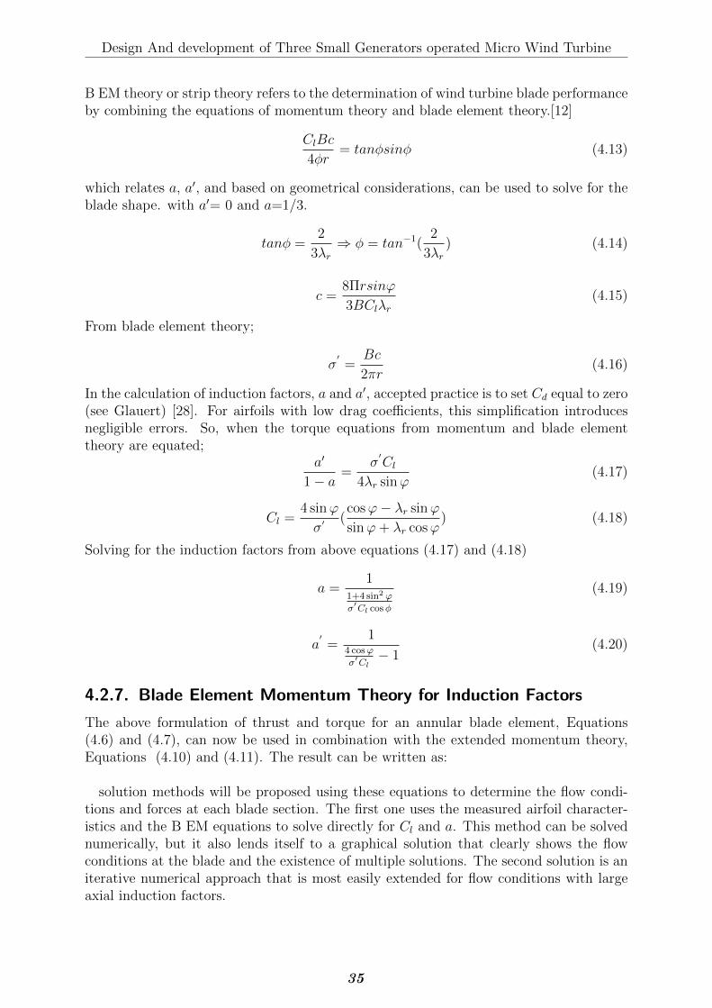
Design And development of Three Small Generators operated Micro Wind Turbine
B EM theory or strip theory refers to the determination of wind turbine blade performanceby combining the equations of momentum theory and blade element theory.[12]
ClBc
4φr= tanφsinφ (4.13)
which relates a, a′, and based on geometrical considerations, can be used to solve for theblade shape. with a′= 0 and a=1/3.
tanφ =2
3λr⇒ φ = tan−1(
2
3λr) (4.14)
c =8Πrsinϕ
3BClλr(4.15)
From blade element theory;
σ′=
Bc
2πr(4.16)
In the calculation of induction factors, a and a′, accepted practice is to set Cd equal to zero(see Glauert) [28]. For airfoils with low drag coefficients, this simplification introducesnegligible errors. So, when the torque equations from momentum and blade elementtheory are equated;
a′
1− a=
σ′Cl
4λr sinϕ(4.17)
Cl =4 sinϕ
σ′ (cosϕ− λr sinϕ
sinϕ+ λr cosϕ) (4.18)
Solving for the induction factors from above equations (4.17) and (4.18)
a =1
1+4 sin2 ϕ
σ′Cl cosφ
(4.19)
a′=
14 cosϕ
σ′Cl− 1
(4.20)
4.2.7. Blade Element Momentum Theory for Induction Factors
The above formulation of thrust and torque for an annular blade element, Equations(4.6) and (4.7), can now be used in combination with the extended momentum theory,Equations (4.10) and (4.11). The result can be written as:
solution methods will be proposed using these equations to determine the flow condi-tions and forces at each blade section. The first one uses the measured airfoil character-istics and the B EM equations to solve directly for Cl and a. This method can be solvednumerically, but it also lends itself to a graphical solution that clearly shows the flowconditions at the blade and the existence of multiple solutions. The second solution is aniterative numerical approach that is most easily extended for flow conditions with largeaxial induction factors.
35
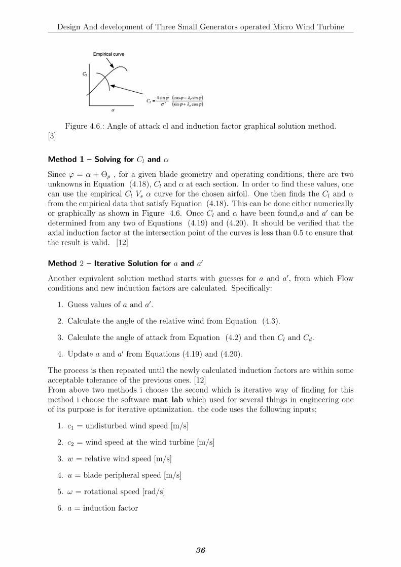
Design And development of Three Small Generators operated Micro Wind Turbine
Figure 4.6.: Angle of attack cl and induction factor graphical solution method.[3]
Method 1 – Solving for Cl and α
Since ϕ = α + Θp , for a given blade geometry and operating conditions, there are twounknowns in Equation (4.18), Cl and α at each section. In order to find these values, onecan use the empirical Cl Vs α curve for the chosen airfoil. One then finds the Cl and αfrom the empirical data that satisfy Equation (4.18). This can be done either numericallyor graphically as shown in Figure 4.6. Once Cl and α have been found,a and a′ can bedetermined from any two of Equations (4.19) and (4.20). It should be verified that theaxial induction factor at the intersection point of the curves is less than 0.5 to ensure thatthe result is valid. [12]
Method 2 – Iterative Solution for a and a′
Another equivalent solution method starts with guesses for a and a′, from which Flowconditions and new induction factors are calculated. Specifically:
1. Guess values of a and a′.
2. Calculate the angle of the relative wind from Equation (4.3).
3. Calculate the angle of attack from Equation (4.2) and then Cl and Cd.
4. Update a and a′ from Equations (4.19) and (4.20).
The process is then repeated until the newly calculated induction factors are within someacceptable tolerance of the previous ones. [12]From above two methods i choose the second which is iterative way of finding for thismethod i choose the software mat lab which used for several things in engineering oneof its purpose is for iterative optimization. the code uses the following inputs;
1. c1 = undisturbed wind speed [m/s]
2. c2 = wind speed at the wind turbine [m/s]
3. w = relative wind speed [m/s]
4. u = blade peripheral speed [m/s]
5. ω = rotational speed [rad/s]
6. a = induction factor
36
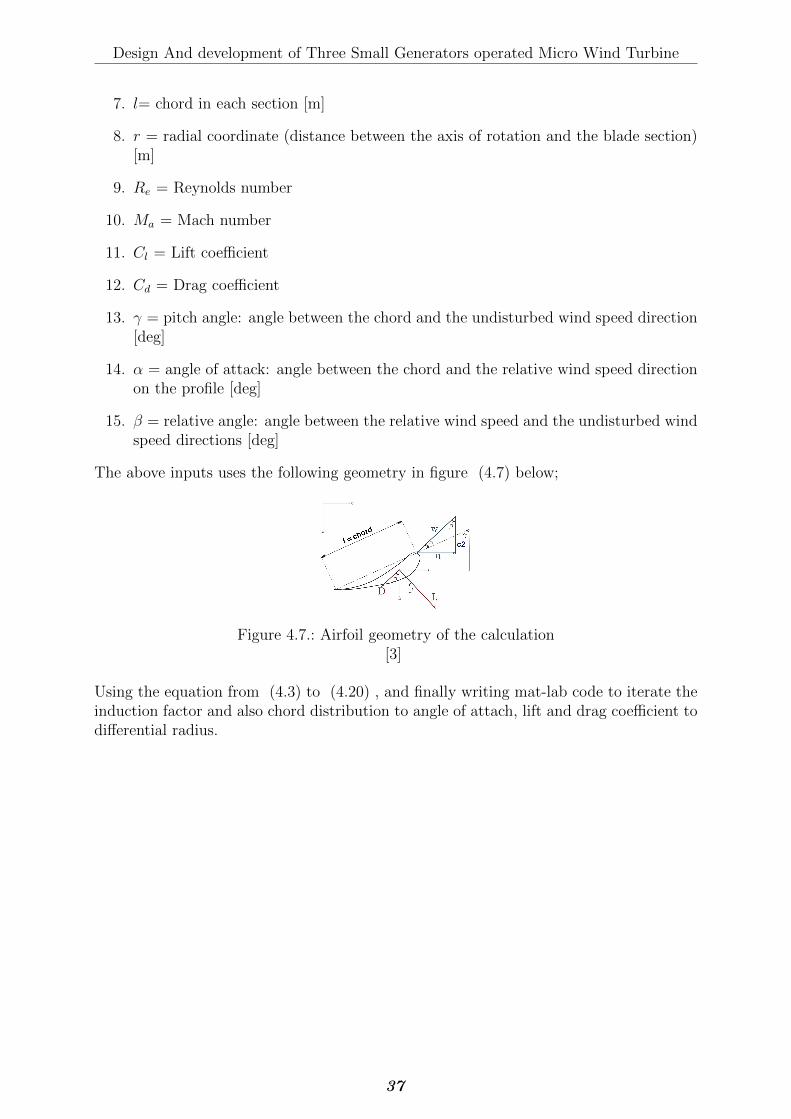
Design And development of Three Small Generators operated Micro Wind Turbine
7. l= chord in each section [m]
8. r = radial coordinate (distance between the axis of rotation and the blade section)[m]
9. Re = Reynolds number
10. Ma = Mach number
11. Cl = Lift coefficient
12. Cd = Drag coefficient
13. γ = pitch angle: angle between the chord and the undisturbed wind speed direction[deg]
14. α = angle of attack: angle between the chord and the relative wind speed directionon the profile [deg]
15. β = relative angle: angle between the relative wind speed and the undisturbed windspeed directions [deg]
The above inputs uses the following geometry in figure (4.7) below;
Figure 4.7.: Airfoil geometry of the calculation[3]
Using the equation from (4.3) to (4.20) , and finally writing mat-lab code to iterate theinduction factor and also chord distribution to angle of attach, lift and drag coefficient todifferential radius.
37
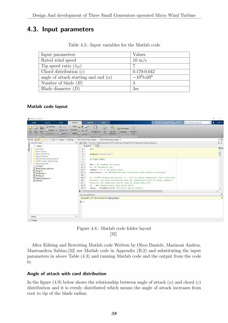
Design And development of Three Small Generators operated Micro Wind Turbine
4.3. Input parameters
Table 4.3.: Input variables for the Matlab code
Input parameters ValuesRated wind speed 10 m/sTip speed ratio (λD) 7Chord distribution (c) 0.179-0.042angle of attach starting and end (α) −100to200
Number of blade (B) 3Blade diameter (D) 3m
Matlab code layout
Figure 4.8.: Matlab code folder layout[32]
After Editing and Rewriting Matlab code Written by Oboe Daniele, Marinoni Andrea,Mastrandrea Sabino,[32] see Matlab code in Appendix (B.2) and substituting the inputparameters in above Table (4.3) and running Matlab code and the output from the codeis;
Angle of attack with cord distribution
In the figure (4.9) below shows the relationship between angle of attack (α) and chord (c)distribution and it is evenly distributed which means the angle of attack increases fromroot to tip of the blade radius.
38
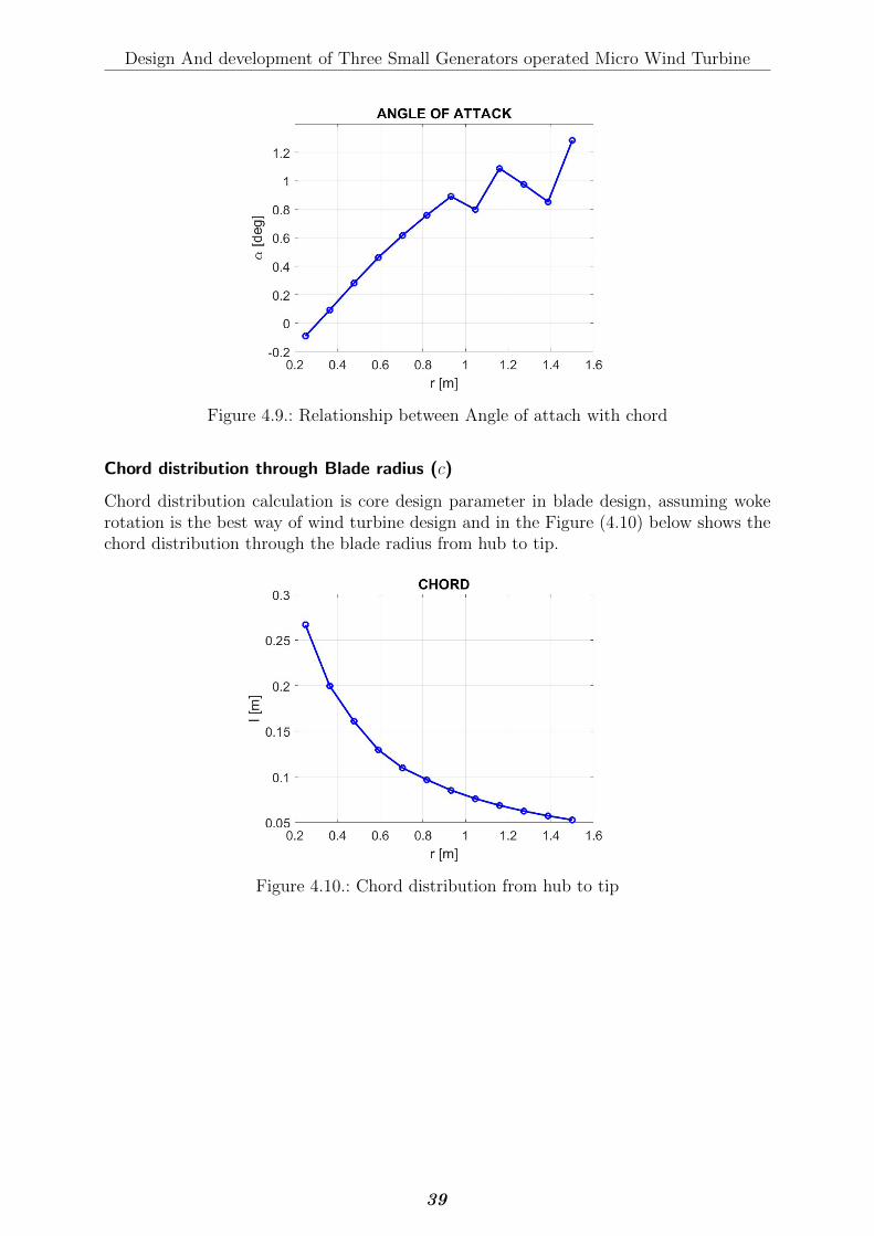
Design And development of Three Small Generators operated Micro Wind Turbine
Figure 4.9.: Relationship between Angle of attach with chord
Chord distribution through Blade radius (c)
Chord distribution calculation is core design parameter in blade design, assuming wokerotation is the best way of wind turbine design and in the Figure (4.10) below shows thechord distribution through the blade radius from hub to tip.
Figure 4.10.: Chord distribution from hub to tip
39
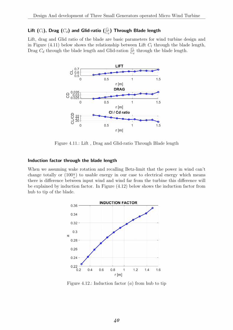
Design And development of Three Small Generators operated Micro Wind Turbine
Lift (Cl), Drag (Cd) and Glid-ratio ( Cl
Cd) Through Blade length
Lift, drag and Glid ratio of the blade are basic parameters for wind turbine design andin Figure (4.11) below shows the relationship between Lift Cl through the blade length,Drag Cd through the blade length and Glid-ration Cl
Cdthrough the blade length.
Figure 4.11.: Lift , Drag and Glid-ratio Through Blade length
Induction factor through the blade length
When we assuming wake rotation and recalling Betz-limit that the power in wind can’tchange totally or (100 0
0) to usable energy in our case to electrical energy which means
there is difference between input wind and wind far from the turbine this difference willbe explained by induction factor. In Figure (4.12) below shows the induction factor fromhub to tip of the blade.
Figure 4.12.: Induction factor (a) from hub to tip
40
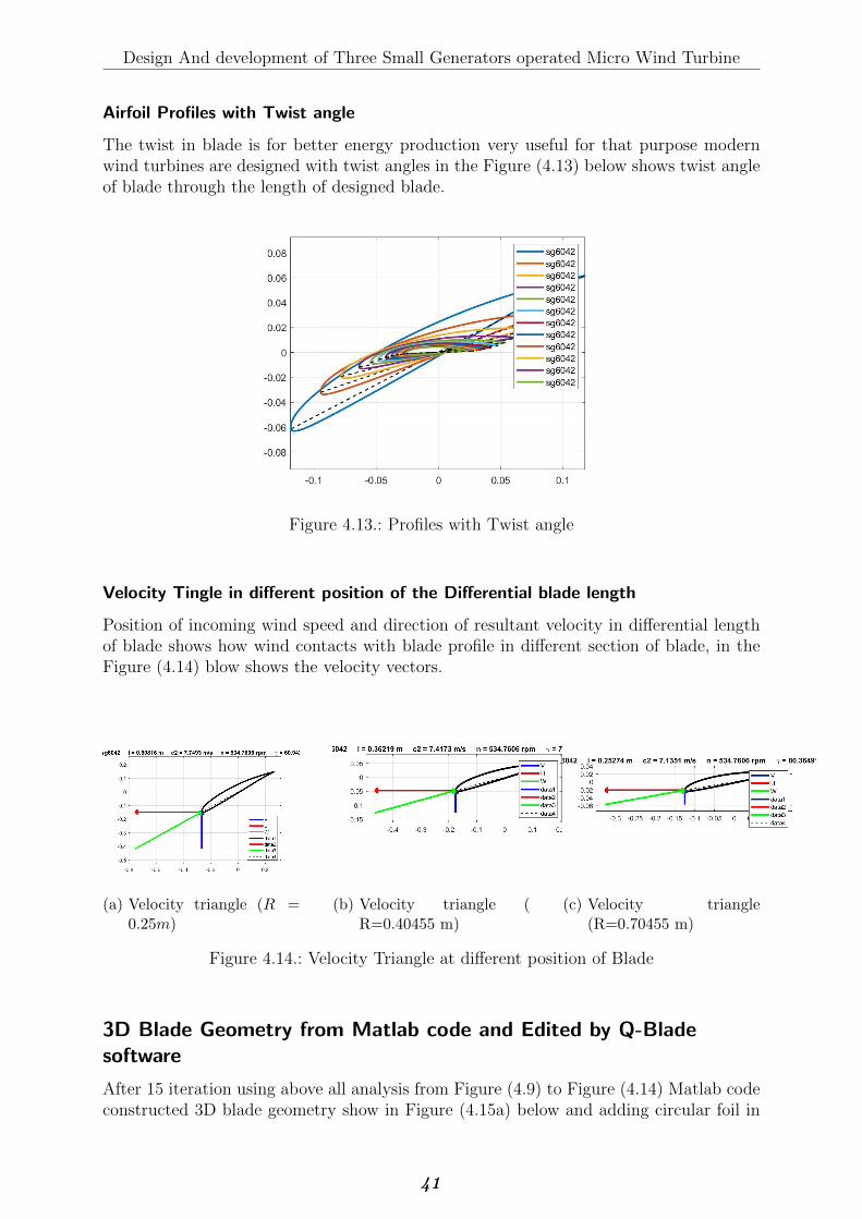
Design And development of Three Small Generators operated Micro Wind Turbine
Airfoil Profiles with Twist angle
The twist in blade is for better energy production very useful for that purpose modernwind turbines are designed with twist angles in the Figure (4.13) below shows twist angleof blade through the length of designed blade.
Figure 4.13.: Profiles with Twist angle
Velocity Tingle in different position of the Differential blade length
Position of incoming wind speed and direction of resultant velocity in differential lengthof blade shows how wind contacts with blade profile in different section of blade, in theFigure (4.14) blow shows the velocity vectors.
(a) Velocity triangle (R =0.25m)
(b) Velocity triangle (R=0.40455 m)
(c) Velocity triangle(R=0.70455 m)
Figure 4.14.: Velocity Triangle at different position of Blade
3D Blade Geometry from Matlab code and Edited by Q-Bladesoftware
After 15 iteration using above all analysis from Figure (4.9) to Figure (4.14) Matlab codeconstructed 3D blade geometry show in Figure (4.15a) below and adding circular foil in
41
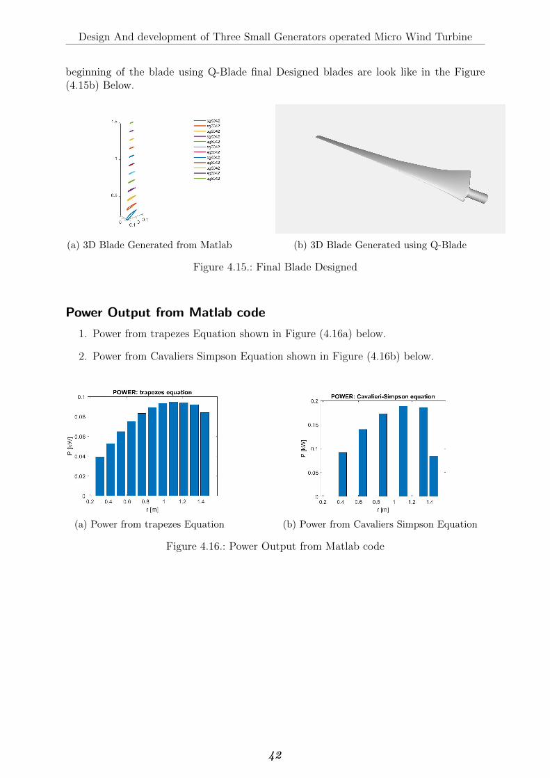
Design And development of Three Small Generators operated Micro Wind Turbine
beginning of the blade using Q-Blade final Designed blades are look like in the Figure(4.15b) Below.
(a) 3D Blade Generated from Matlab (b) 3D Blade Generated using Q-Blade
Figure 4.15.: Final Blade Designed
Power Output from Matlab code
1. Power from trapezes Equation shown in Figure (4.16a) below.
2. Power from Cavaliers Simpson Equation shown in Figure (4.16b) below.
(a) Power from trapezes Equation (b) Power from Cavaliers Simpson Equation
Figure 4.16.: Power Output from Matlab code
42
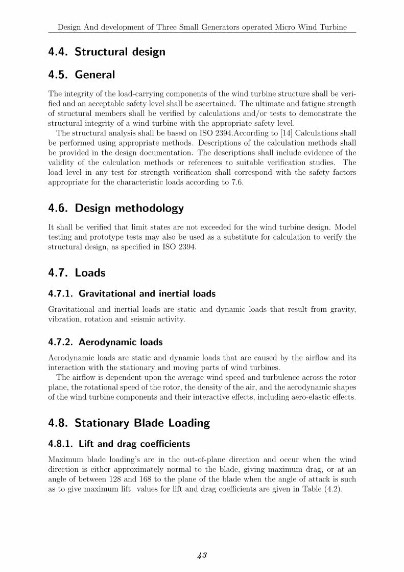
Design And development of Three Small Generators operated Micro Wind Turbine
4.4. Structural design
4.5. General
The integrity of the load-carrying components of the wind turbine structure shall be veri-fied and an acceptable safety level shall be ascertained. The ultimate and fatigue strengthof structural members shall be verified by calculations and/or tests to demonstrate thestructural integrity of a wind turbine with the appropriate safety level.
The structural analysis shall be based on ISO 2394.According to [14] Calculations shallbe performed using appropriate methods. Descriptions of the calculation methods shallbe provided in the design documentation. The descriptions shall include evidence of thevalidity of the calculation methods or references to suitable verification studies. Theload level in any test for strength verification shall correspond with the safety factorsappropriate for the characteristic loads according to 7.6.
4.6. Design methodology
It shall be verified that limit states are not exceeded for the wind turbine design. Modeltesting and prototype tests may also be used as a substitute for calculation to verify thestructural design, as specified in ISO 2394.
4.7. Loads
4.7.1. Gravitational and inertial loads
Gravitational and inertial loads are static and dynamic loads that result from gravity,vibration, rotation and seismic activity.
4.7.2. Aerodynamic loads
Aerodynamic loads are static and dynamic loads that are caused by the airflow and itsinteraction with the stationary and moving parts of wind turbines.
The airflow is dependent upon the average wind speed and turbulence across the rotorplane, the rotational speed of the rotor, the density of the air, and the aerodynamic shapesof the wind turbine components and their interactive effects, including aero-elastic effects.
4.8. Stationary Blade Loading
4.8.1. Lift and drag coefficients
Maximum blade loading’s are in the out-of-plane direction and occur when the winddirection is either approximately normal to the blade, giving maximum drag, or at anangle of between 128 and 168 to the plane of the blade when the angle of attack is suchas to give maximum lift. values for lift and drag coefficients are given in Table (4.2).
43

Design And development of Three Small Generators operated Micro Wind Turbine
4.8.2. Dynamic response
Tip displacement
Wind fluctuations at frequencies close to the first flap-wise mode blade natural frequencyexcite resonant blade oscillations and result in additional, inertial loading’s over andabove the quasi-static loads that would be experienced by a completely rigid blade. Asthe oscillatory motion result from unstable of the wind speed about the average value,the standard deviation of resonant tip displacement can be explained in terms of the windUnstable intensity and the normalized power spectral density at the resonant frequency,
44
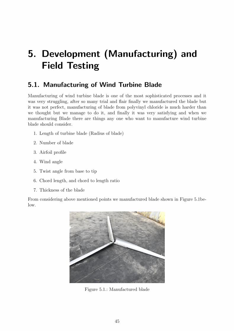
5. Development (Manufacturing) andField Testing
5.1. Manufacturing of Wind Turbine Blade
Manufacturing of wind turbine blade is one of the most sophisticated processes and itwas very struggling, after so many trial and flair finally we manufactured the blade butit was not perfect, manufacturing of blade from polyvinyl chloride is much harder thanwe thought but we manage to do it, and finally it was very satisfying and when wemanufacturing Blade there are things any one who want to manufacture wind turbineblade should consider.
1. Length of turbine blade (Radius of blade)
2. Number of blade
3. Airfoil profile
4. Wind angle
5. Twist angle from base to tip
6. Chord length, and chord to length ratio
7. Thickness of the blade
From considering above mentioned points we manufactured blade shown in Figure 5.1be-low.
Figure 5.1.: Manufactured blade
45
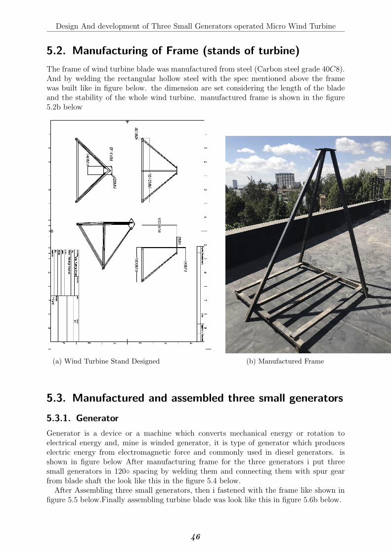
Design And development of Three Small Generators operated Micro Wind Turbine
5.2. Manufacturing of Frame (stands of turbine)
The frame of wind turbine blade was manufactured from steel (Carbon steel grade 40C8).And by welding the rectangular hollow steel with the spec mentioned above the framewas built like in figure below. the dimension are set considering the length of the bladeand the stability of the whole wind turbine. manufactured frame is shown in the figure5.2b below
(a) Wind Turbine Stand Designed (b) Manufactured Frame
5.3. Manufactured and assembled three small generators
5.3.1. Generator
Generator is a device or a machine which converts mechanical energy or rotation toelectrical energy and, mine is winded generator, it is type of generator which produceselectric energy from electromagnetic force and commonly used in diesel generators. isshown in figure below After manufacturing frame for the three generators i put threesmall generators in 120◦ spacing by welding them and connecting them with spur gearfrom blade shaft the look like this in the figure 5.4 below.
After Assembling three small generators, then i fastened with the frame like shown infigure 5.5 below.Finally assembling turbine blade was look like this in figure 5.6b below.
46
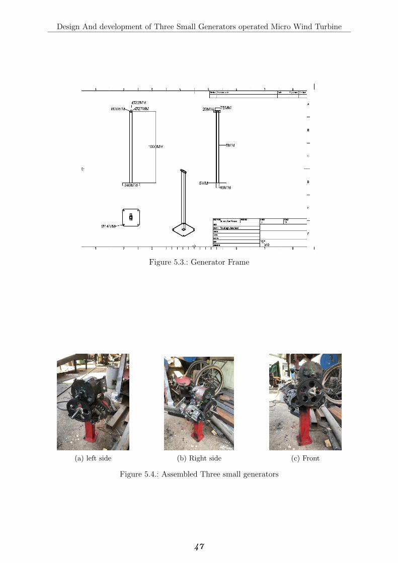
Design And development of Three Small Generators operated Micro Wind Turbine
Figure 5.3.: Generator Frame
(a) left side (b) Right side (c) Front
Figure 5.4.: Assembled Three small generators
47
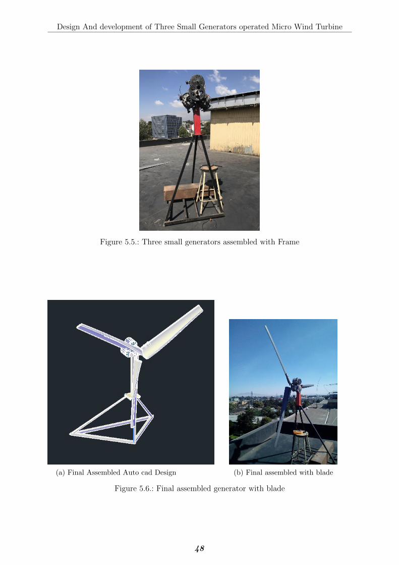
Design And development of Three Small Generators operated Micro Wind Turbine
Figure 5.5.: Three small generators assembled with Frame
(a) Final Assembled Auto cad Design (b) Final assembled with blade
Figure 5.6.: Final assembled generator with blade
48
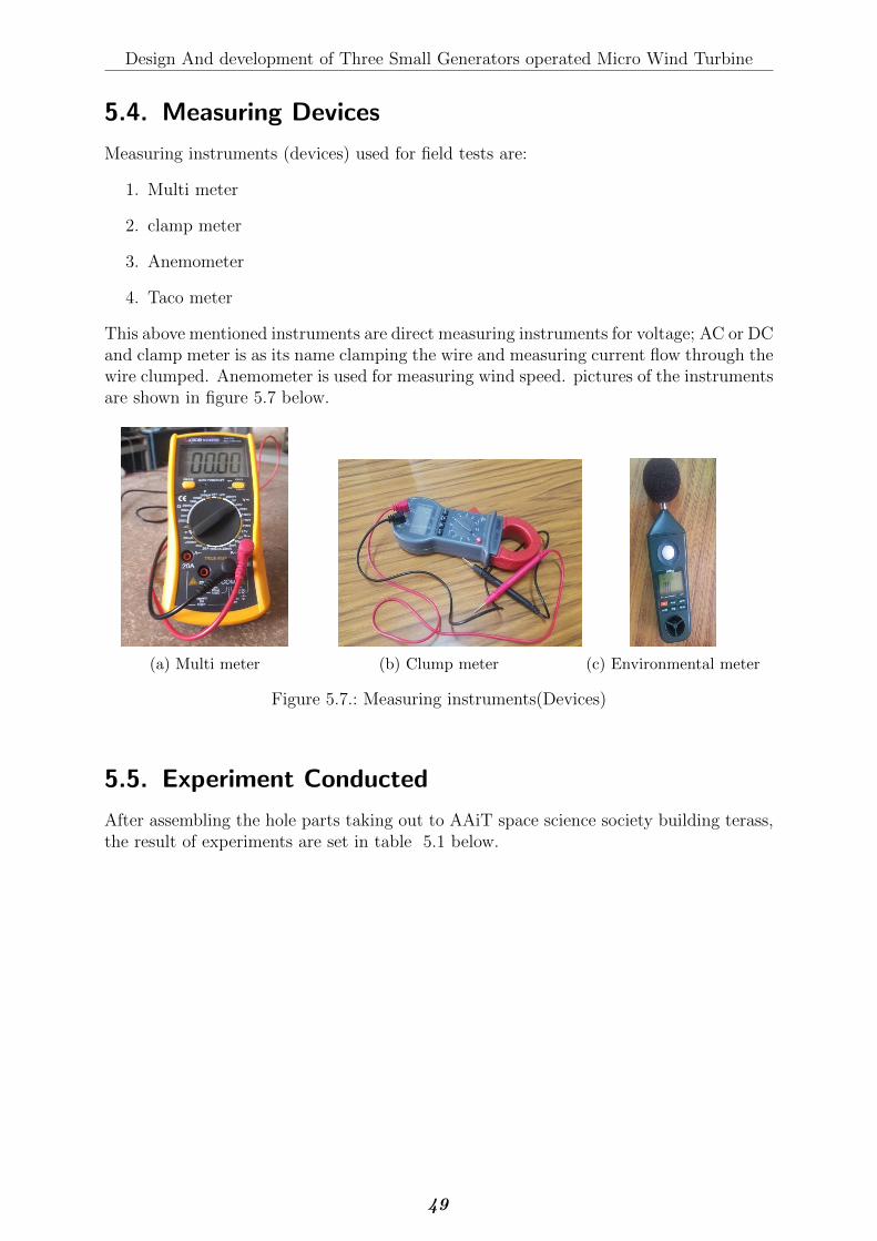
Design And development of Three Small Generators operated Micro Wind Turbine
5.4. Measuring Devices
Measuring instruments (devices) used for field tests are:
1. Multi meter
2. clamp meter
3. Anemometer
4. Taco meter
This above mentioned instruments are direct measuring instruments for voltage; AC or DCand clamp meter is as its name clamping the wire and measuring current flow through thewire clumped. Anemometer is used for measuring wind speed. pictures of the instrumentsare shown in figure 5.7 below.
(a) Multi meter (b) Clump meter (c) Environmental meter
Figure 5.7.: Measuring instruments(Devices)
5.5. Experiment Conducted
After assembling the hole parts taking out to AAiT space science society building terass,the result of experiments are set in table 5.1 below.
49
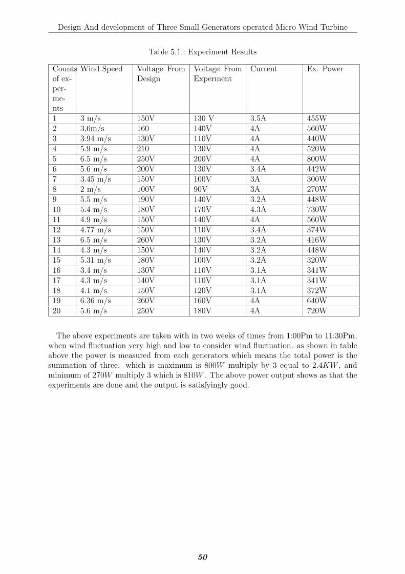
Design And development of Three Small Generators operated Micro Wind Turbine
Table 5.1.: Experiment Results
Countsof ex-per-me-nts
Wind Speed Voltage FromDesign
Voltage FromExperment
Current Ex. Power
1 3 m/s 150V 130 V 3.5A 455W2 3.6m/s 160 140V 4A 560W3 3.94 m/s 130V 110V 4A 440W4 5.9 m/s 210 130V 4A 520W5 6.5 m/s 250V 200V 4A 800W6 5.6 m/s 200V 130V 3.4A 442W7 3.45 m/s 150V 100V 3A 300W8 2 m/s 100V 90V 3A 270W9 5.5 m/s 190V 140V 3.2A 448W10 5.4 m/s 180V 170V 4.3A 730W11 4.9 m/s 150V 140V 4A 560W12 4.77 m/s 150V 110V 3.4A 374W13 6.5 m/s 260V 130V 3.2A 416W14 4.3 m/s 150V 140V 3.2A 448W15 5.31 m/s 180V 100V 3.2A 320W16 3.4 m/s 130V 110V 3.1A 341W17 4.3 m/s 140V 110V 3.1A 341W18 4.1 m/s 150V 120V 3.1A 372W19 6.36 m/s 260V 160V 4A 640W20 5.6 m/s 250V 180V 4A 720W
The above experiments are taken with in two weeks of times from 1:00Pm to 11:30Pm,when wind fluctuation very high and low to consider wind fluctuation. as shown in tableabove the power is measured from each generators which means the total power is thesummation of three. which is maximum is 800W multiply by 3 equal to 2.4KW , andminimum of 270W multiply 3 which is 810W . The above power output shows as that theexperiments are done and the output is satisfyingly good.
50
6. Conclusion and Recommendation
6.1. Conclusion
Following the mathematical model developed by different authors as a guidance a, math-ematical model was developed for this study. For rural and remote part of Ethiopiaelectrical application, the design of 3KW power output the modeling methodology waspresented with momentum equation, Blade element moment equation and energy equa-tion. MATLAB software is used to obtain the solution of the model developed, fromthe output of Matlab code and Mathematical model, wind turbine blade is designed andmanufactured,The rest of Structure is designed and manufactured according to mechan-ical design. Solid Work-2019 and Auto-cad 2020 is used for geometrical modeling of thedevelopment. The experiment is conducted from manufactured Three small generator op-erated direct drive wind turbine placed in AAiT Science society building Top, by settingup materials like, Multi meter, Clump meter, and Anemometer. Following the result fromthe experiment conducted the following conclusion are drawn.
� Because of low PVC weight, turbine can rotate with low wind speed specificallywith wind speed of 5.5 to 6.5m/s.
� Due to PVC pre-made Shape, making Twist angle for better wind harness was quitepromising.
� The designed blade is more effective after first rotation, after first rotation bladecan rotate for 5 seconds with same RPM even wind speed is dropping because oflight weight and best twist angle.
� After Rated wind speed achieved Turbine works perfectly and generates designedpower output.
� The experimental data and simulated data collected has a similarities and variationthroughout, the variation is a result of fluctuation of the wind in test site.
� The designed Wind turbine generates 2.4 KW energy at rated wind speed and above.
6.2. Recommendation
In the future, in order to increase the efficiency of Three small generator operated directdrive wind turbine the following basic recommendation are made
1. For better wind harness, the yaw mechanism can added and can increase windcontact area.
2. Break system is main component of wind turbine and for the future work, the lifeexpectense can be increase when break system applied.
51

Design And development of Three Small Generators operated Micro Wind Turbine
3. PVC can be molded, for better airfoil shape, molding can increase the efficiency ofthe turbine Blade.
4. Finally Wind Generators are replaceable and if efficient generators applied powerout put can increase and by reducing RPM can generate more power with less winspeed.
52
Bibliography
[1] D. K. B. Asis Sarkar, “Wind turbine blade efficiency and power calculation withelectrical analogy,” International Journal of Scientific and Research Publications,vol. Volume 2, no. Issue 2, p. 5, 2012.
[2] A. Alene, “Design and analysis of bamboo and e-glass fiber reinforced epoxy hybridcomposite for wind turbine blade shell,” Master’s thesis, ADDIS ABABA UNIVER-SITY INSTITUTE OF TECHNOLOGY, 2013.
[3] B. BERGES, Development of Small Wind Turbines. Thesis, 2007.
[4] G. L. Johnson, Wind Energy Systems. Manhattan, KS: precentice Hill, electronicedition ed., 1985.
[5] F. J. BARTOS, “Direct-drive wind turbines flex muscles,” 06 2011.
[6] S. Mathew, Wind Energy Fundamentals, Resource Analysis and Economics. Springer-Verlag Berlin Heidelberg, 2006.
[7] D. W. I. Association, “Guided tour on wind energy,” 2002.
[8] G. Ingram, Wind Turbine Blade Analysis using the Blade Element MomentumMethod. Thesis, 2011.
[9] D. K. S. S. Mulugeta Biadgo Asress, Aleksandar Simonovic, “Wind energy resourcedevelopment in ethiopia as an alternative energy future beyond the dominant hy-dropower,” elsevier, no. 21 February 2013, p. 13, 2013.
[10] P. Jain, Wind Energy Engineering, vol. I. New York, Chicago San Francisco,Lisbon,London, Madrid, Mexico City, Milan, New Delhi, San Juan, Seoul, Singapore, SydneyToronto.: McGraw-Hill Companies, Inc, 1st ed., 2011.
[11] L. Morris, “Direct drive vs. gearbox: Progress on both fronts,” 08 2017.
[12] A. L. R. J. F. Manwell, J. G. McGowan, WIND ENERGY EXPLAINED Theory, De-sign and Application. United Kingdom: John Wiley & Sons Ltd, second edition ed.,2009.
[13] N. J. E. B. Tony Burton, David Sharpe, WIND ENERGY HANDBOOK. Chichester� New York � Weinheim � Brisbane � Singapore � Toronto: JOHN WILEY SONS,LTD, 1st ed., 2001.
[14] IEC, “(iec 61400.1) iec wind turbines part 1 design requirements international elec-trotechnical commission,” 12-2013 2013.
[15] W. P. Limited, Advances in wind turbine blade design and materials, vol. III of Wood-head Publishing Series in Energy: Number 47. Oxford, Cambridge, Philadelphia, NewDelhi: Woodhead Publishing Limited, 3rd ed., 2013.
53
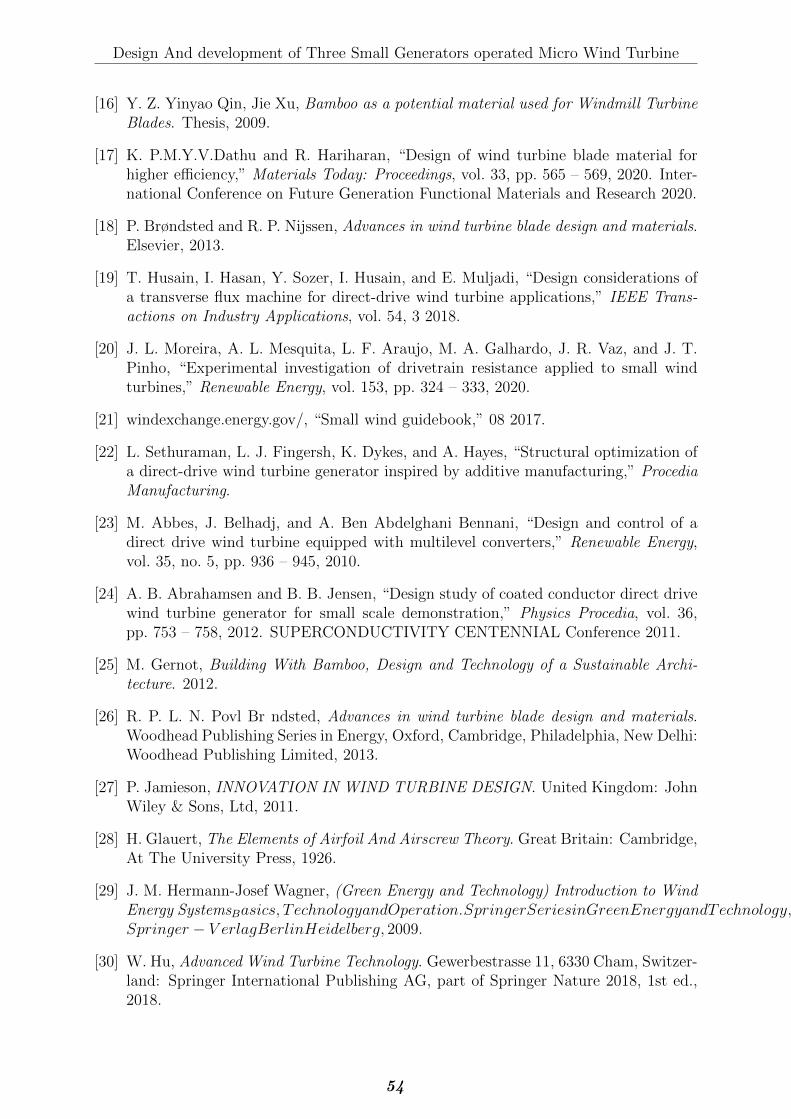
Design And development of Three Small Generators operated Micro Wind Turbine
[16] Y. Z. Yinyao Qin, Jie Xu, Bamboo as a potential material used for Windmill TurbineBlades. Thesis, 2009.
[17] K. P.M.Y.V.Dathu and R. Hariharan, “Design of wind turbine blade material forhigher efficiency,” Materials Today: Proceedings, vol. 33, pp. 565 – 569, 2020. Inter-national Conference on Future Generation Functional Materials and Research 2020.
[18] P. Brøndsted and R. P. Nijssen, Advances in wind turbine blade design and materials.Elsevier, 2013.
[19] T. Husain, I. Hasan, Y. Sozer, I. Husain, and E. Muljadi, “Design considerations ofa transverse flux machine for direct-drive wind turbine applications,” IEEE Trans-actions on Industry Applications, vol. 54, 3 2018.
[20] J. L. Moreira, A. L. Mesquita, L. F. Araujo, M. A. Galhardo, J. R. Vaz, and J. T.Pinho, “Experimental investigation of drivetrain resistance applied to small windturbines,” Renewable Energy, vol. 153, pp. 324 – 333, 2020.
[21] windexchange.energy.gov/, “Small wind guidebook,” 08 2017.
[22] L. Sethuraman, L. J. Fingersh, K. Dykes, and A. Hayes, “Structural optimization ofa direct-drive wind turbine generator inspired by additive manufacturing,” ProcediaManufacturing.
[23] M. Abbes, J. Belhadj, and A. Ben Abdelghani Bennani, “Design and control of adirect drive wind turbine equipped with multilevel converters,” Renewable Energy,vol. 35, no. 5, pp. 936 – 945, 2010.
[24] A. B. Abrahamsen and B. B. Jensen, “Design study of coated conductor direct drivewind turbine generator for small scale demonstration,” Physics Procedia, vol. 36,pp. 753 – 758, 2012. SUPERCONDUCTIVITY CENTENNIAL Conference 2011.
[25] M. Gernot, Building With Bamboo, Design and Technology of a Sustainable Archi-tecture. 2012.
[26] R. P. L. N. Povl Br ndsted, Advances in wind turbine blade design and materials.Woodhead Publishing Series in Energy, Oxford, Cambridge, Philadelphia, New Delhi:Woodhead Publishing Limited, 2013.
[27] P. Jamieson, INNOVATION IN WIND TURBINE DESIGN. United Kingdom: JohnWiley & Sons, Ltd, 2011.
[28] H. Glauert, The Elements of Airfoil And Airscrew Theory. Great Britain: Cambridge,At The University Press, 1926.
[29] J. M. Hermann-Josef Wagner, (Green Energy and Technology) Introduction to WindEnergy SystemsBasics, TechnologyandOperation.SpringerSeriesinGreenEnergyandTechnology, SpringerHeidelberg,Dordrecht, London,NewY ork :Springer − V erlagBerlinHeidelberg, 2009.
[30] W. Hu, Advanced Wind Turbine Technology. Gewerbestrasse 11, 6330 Cham, Switzer-land: Springer International Publishing AG, part of Springer Nature 2018, 1st ed.,2018.
54

Design And development of Three Small Generators operated Micro Wind Turbine
[31] J. Government, “Study on the energy sector in ethiopia.”
[32] Preliminary Design of Horizontal Axis Wind Turbine blades.
55

Appendices
56

Design And development of Three Small Generators operated Micro Wind Turbine
A.1. Design Detail Drawing
57
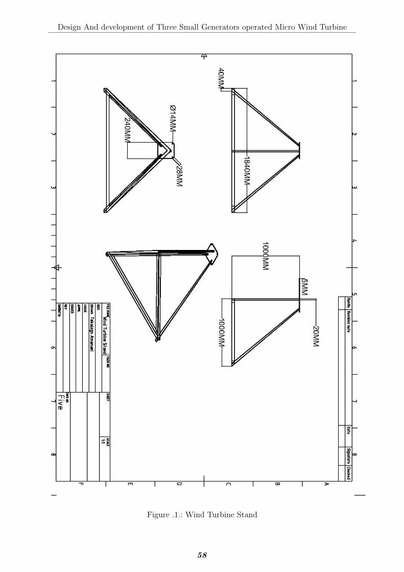
Design And development of Three Small Generators operated Micro Wind Turbine
Figure .1.: Wind Turbine Stand
58
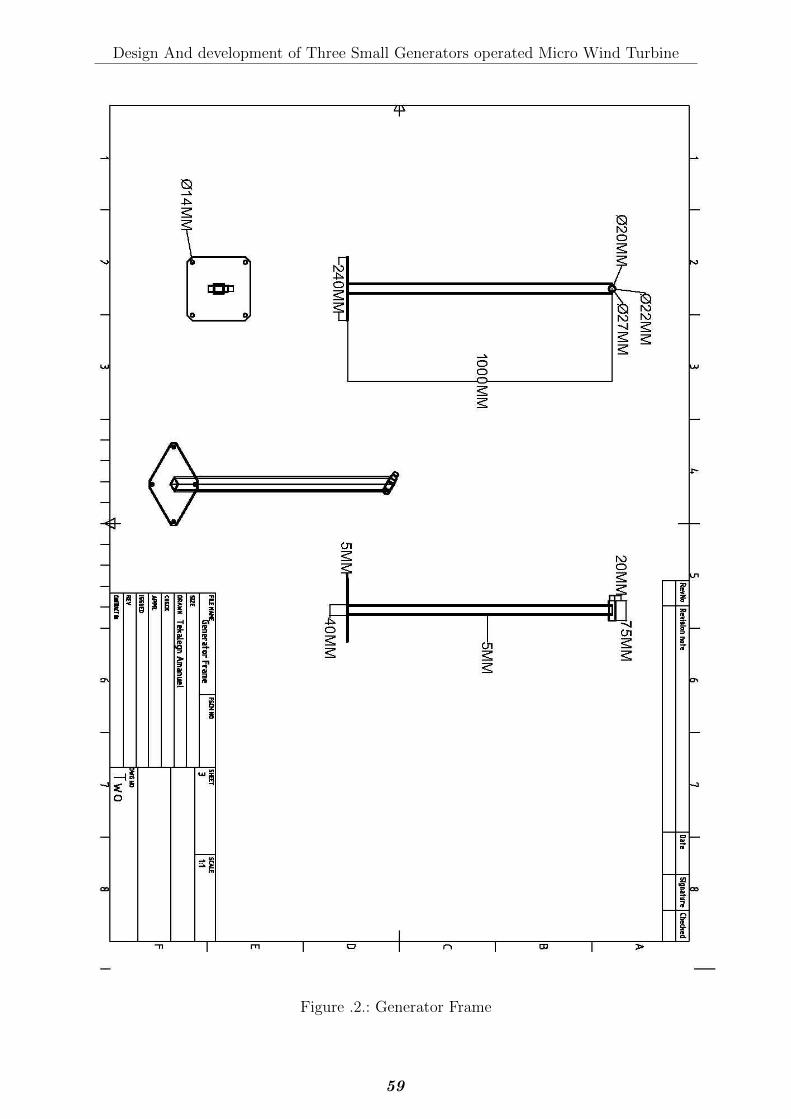
Design And development of Three Small Generators operated Micro Wind Turbine
Figure .2.: Generator Frame
59
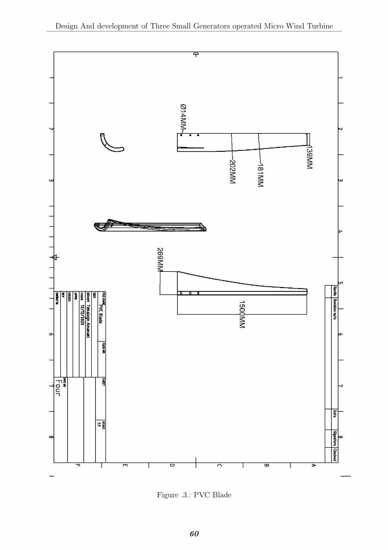
Design And development of Three Small Generators operated Micro Wind Turbine
Figure .3.: PVC Blade
60
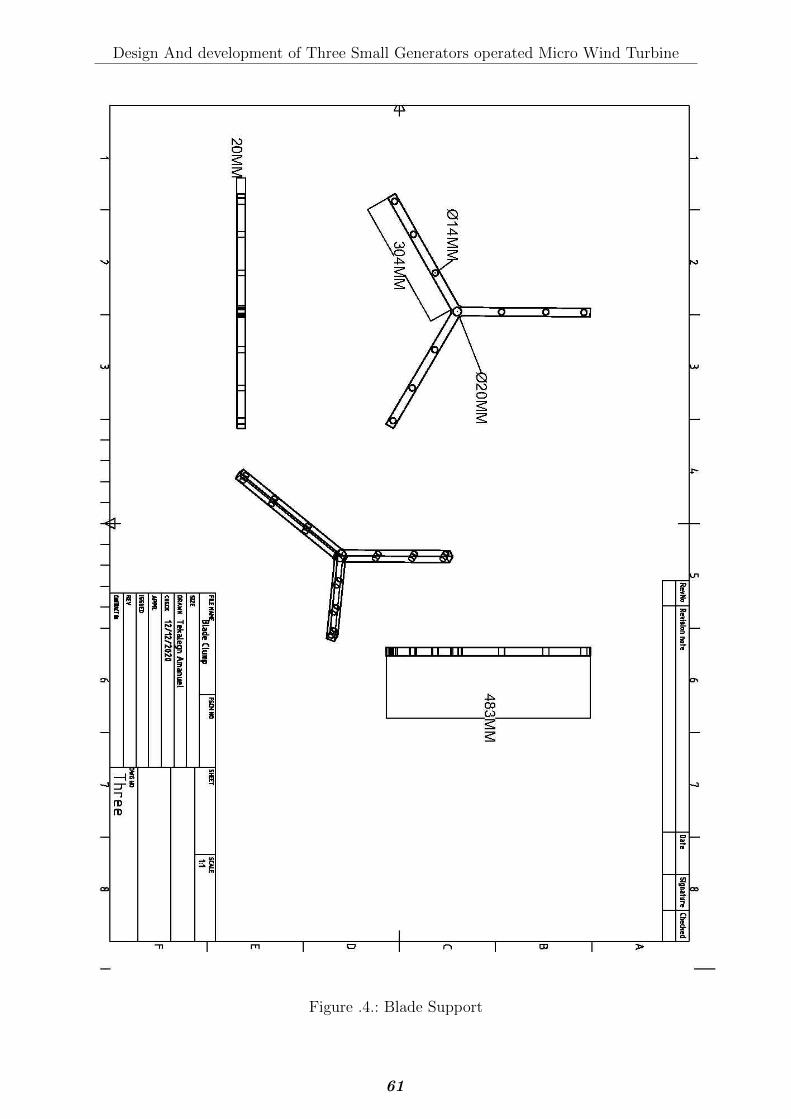
Design And development of Three Small Generators operated Micro Wind Turbine
Figure .4.: Blade Support
61
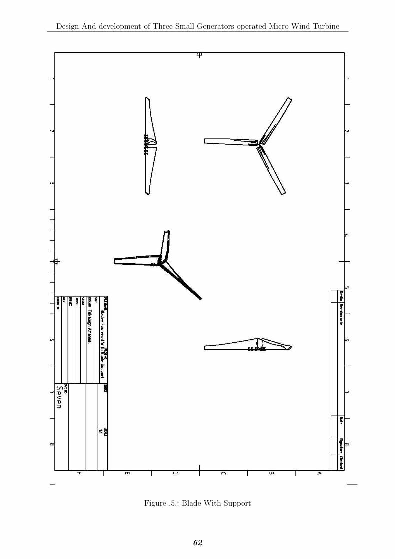
Design And development of Three Small Generators operated Micro Wind Turbine
Figure .5.: Blade With Support
62

Design And development of Three Small Generators operated Micro Wind Turbine
Figure .6.: Final Assembled Wind Turbine
63
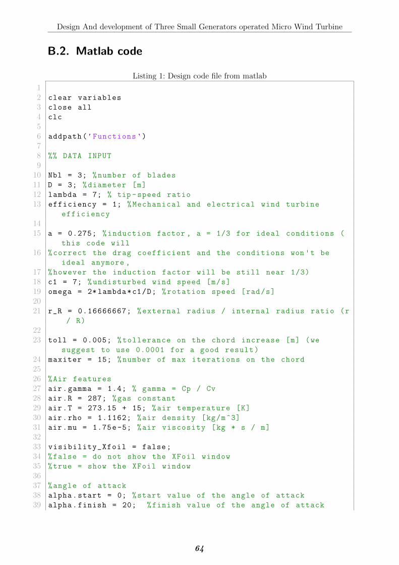
Design And development of Three Small Generators operated Micro Wind Turbine
B.2. Matlab code
Listing 1: Design code file from matlab
12 clear variables
3 close all
4 clc
56 addpath('Functions ')
78 %% DATA INPUT
910 Nbl = 3; %number of blades
11 D = 3; %diameter [m]
12 lambda = 7; % tip -speed ratio
13 efficiency = 1; %Mechanical and electrical wind turbine
efficiency
1415 a = 0.275; %induction factor , a = 1/3 for ideal conditions (
this code will
16 %correct the drag coefficient and the conditions won 't be
ideal anymore ,
17 %however the induction factor will be still near 1/3)
18 c1 = 7; %undisturbed wind speed [m/s]
19 omega = 2* lambda*c1/D; %rotation speed [rad/s]
2021 r_R = 0.16666667; %external radius / internal radius ratio (r
/ R)
2223 toll = 0.005; %tollerance on the chord increase [m] (we
suggest to use 0.0001 for a good result)
24 maxiter = 15; %number of max iterations on the chord
2526 %Air features
27 air.gamma = 1.4; % gamma = Cp / Cv
28 air.R = 287; %gas constant
29 air.T = 273.15 + 15; %air temperature [K]
30 air.rho = 1.1162; %air density [kg/m^3]
31 air.mu = 1.75e-5; %air viscosity [kg * s / m]
3233 visibility_Xfoil = false;
34 %false = do not show the XFoil window
35 %true = show the XFoil window
3637 %angle of attack
38 alpha.start = 0; %start value of the angle of attack
39 alpha.finish = 20; %finish value of the angle of attack
64
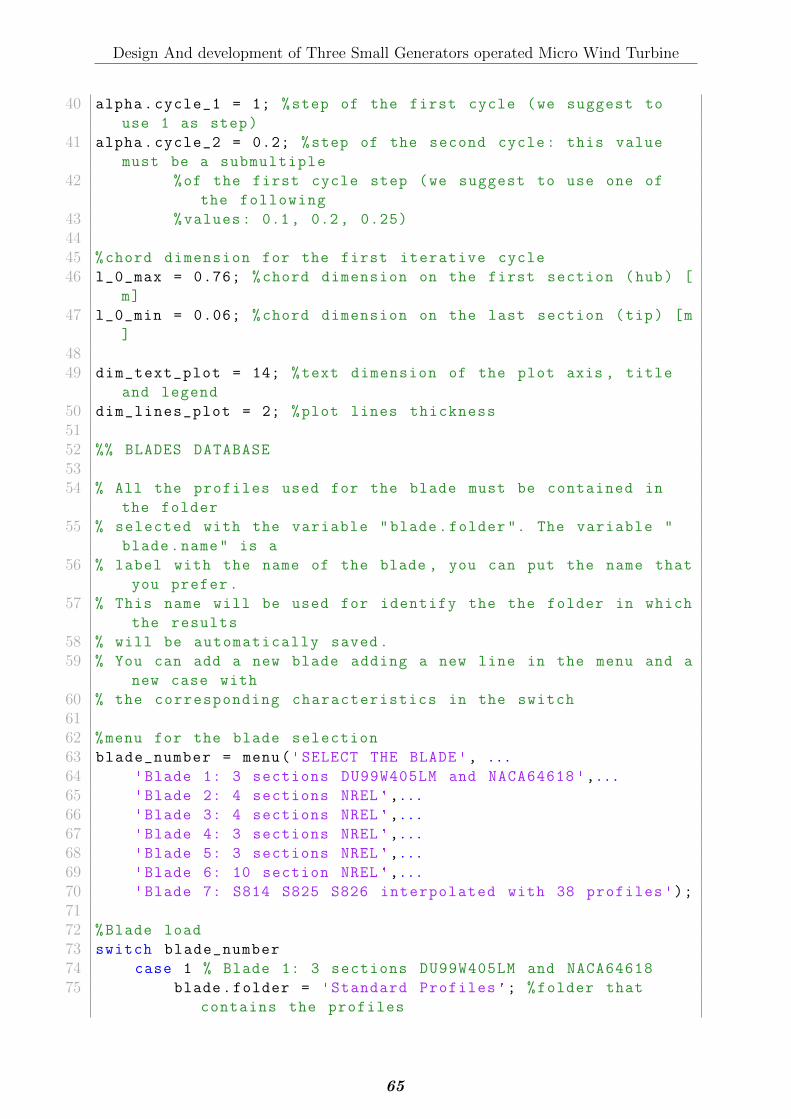
Design And development of Three Small Generators operated Micro Wind Turbine
40 alpha.cycle_1 = 1; %step of the first cycle (we suggest to
use 1 as step)
41 alpha.cycle_2 = 0.2; %step of the second cycle: this value
must be a submultiple
42 %of the first cycle step (we suggest to use one of
the following
43 %values: 0.1, 0.2, 0.25)
4445 %chord dimension for the first iterative cycle
46 l_0_max = 0.76; %chord dimension on the first section (hub) [
m]
47 l_0_min = 0.06; %chord dimension on the last section (tip) [m
]
4849 dim_text_plot = 14; %text dimension of the plot axis , title
and legend
50 dim_lines_plot = 2; %plot lines thickness
5152 %% BLADES DATABASE
5354 % All the profiles used for the blade must be contained in
the folder
55 % selected with the variable "blade.folder ". The variable "
blade.name" is a
56 % label with the name of the blade , you can put the name that
you prefer.
57 % This name will be used for identify the the folder in which
the results
58 % will be automatically saved.
59 % You can add a new blade adding a new line in the menu and a
new case with
60 % the corresponding characteristics in the switch
6162 %menu for the blade selection
63 blade_number = menu('SELECT THE BLADE', ...
64 'Blade 1: 3 sections DU99W405LM and NACA64618 ',...
65 'Blade 2: 4 sections NREL',...
66 'Blade 3: 4 sections NREL',...
67 'Blade 4: 3 sections NREL',...
68 'Blade 5: 3 sections NREL',...
69 'Blade 6: 10 section NREL',...
70 'Blade 7: S814 S825 S826 interpolated with 38 profiles ');
7172 %Blade load
73 switch blade_number
74 case 1 % Blade 1: 3 sections DU99W405LM and NACA64618
75 blade.folder = 'Standard Profiles '; %folder that
contains the profiles
65
Design And development of Three Small Generators operated Micro Wind Turbine
76 blade.name = 'Blade 1'; %name of the blade
77 blade.profiles = {'DU97W300LM.dat','DU91W2250LM.dat',
'NACA64618.dat'}; %profiles
78 % in array and linspaced fron the hub to the tip
79 case 2 % Blade 2: 4 sections NREL
80 blade.folder = 'Standard Profiles ';
81 blade.name = 'Blade 2';
82 blade.profiles = {'s814.dat', 's809.dat','s810.dat'};
83 case 3 % Blade 3: 4 sections NREL
84 blade.folder = 'Standard Profiles ';
85 blade.name = 'Blade 3';
86 blade.profiles = {'s814.dat', 's812.dat', 's813.dat'
};
87 case 4 % Blade 4: 3 sections NREL
88 blade.folder = 'Standard Profiles ';
89 blade.name = 'Blade 4';
90 blade.profiles = {'s818.dat','s816.dat','s817.dat'};
91 case 5 % Blade 5: 3 sections NREL
92 blade.folder = 'Standard Profiles ';
93 blade.name = 'Blade 5';
94 blade.profiles = {'S814.dat', 'S825.dat', 'S826.dat'
};
95 case 6 % Blade 6: 10 sections NREL
96 blade.folder = 'SG6045_Airfoil__Blade_Design ';
97 blade.name = 'Blade 6';
98 blade.profiles = {'sg6042.dat', 'sg6042.dat', 'sg6042
.dat','sg6042.dat','sg6042.dat','sg6042.dat','
sg6042.dat','sg6042.dat','sg6042.dat','sg6042.dat'
,'sg6042.dat','sg6042.dat' ,};
99 case 7 % Blade 6: S814 S825 S826 interpolated with 38
profiles
100 %This is the final blade we have designed during our
project.
101 blade.folder = 'S814_825_826_interpolated_38 ';
102 blade.name = 'Final blade ';
103 blade.profiles = {'s814.dat','s814825_95.dat','
s814825_90.dat','s814825_85.dat','s814825_80.dat',
's814825_75.dat',...
104 's814825_70.dat','s814825_65.dat','s814825_60.dat
','s814825_55.dat','s814825_50.dat','
s814825_45.dat',...
105 's814825_40.dat','s814825_35.dat','s814825_30.dat
','s814825_25.dat','s814825_20.dat','
s814825_15.dat',...
106 's814825_10.dat','s814825_5.dat','s825.dat','
s825826_95.dat','s825826_90.dat','s825826_85.
dat',...
66
Design And development of Three Small Generators operated Micro Wind Turbine
107 's825826_80.dat','s825826_75.dat','s825826_70.dat
','s825826_65.dat','s825826_60.dat','
s825826_55.dat',...
108 's825826_50.dat','s825826_45.dat','s825826_40.dat
','s825826_35.dat','s825826_30.dat','
s825826_25.dat',...
109 's825826_20.dat','s825826_15.dat','s825826_10.dat
','s825826_5.dat','s826.dat'};
110111 otherwise
112 error('The blade selected do not exist in the
database ')
113 end
114115 %% PRE - ANALYSIS CHECKS
116117 %check if the blase folder exist
118 if exist(blade.folder , 'dir')~=7
119 error('Error: the blade folder selected do not exist ')
120 end
121122 %check if all the profiles exist inside the blade folder
123 for ii=1: length(blade.profiles)
124 if exist ([ blade.folder '/' char(blade.profiles(ii))], '
file')~=2
125 error(['Error: Profile ' char(blade.profile(ii)) ' is
missing from the folder '])
126 end
127 end
128129 %% DESIGN
130131 % Recalls the function for the preliminary blade design
132 [blade_design] = Blade_Design(blade , Nbl , D, omega , air ,
efficiency , a, c1, r_R , alpha , toll , maxiter , l_0_max ,
l_0_min , dim_text_plot , dim_lines_plot , visibility_Xfoil);
67

Design And development of Three Small Generators operated Micro Wind Turbine
Listing 2: Off Design code file from matlab
1 %% OFF - DESIGN HORIZONTAL AXIS WIND TURBINE BLADES
2 %
3 %
4 % This code calculates the power produced by a wind turbine
in off -design
5 % conditions. You have to copy in the Current Folder the
Matlab file
6 % "Blade_Design_data.mat" created with the Design script ,
this file
7 % contains all the blade design information. You can set the
off -design
8 % wind speed and the other variables to calculate the power
produced.
910 clear variables
11 close all
12 clc
1314 addpath('Functions ')
1516 disp('PRELIMINARY DESIGN OF HORIZONTAL WIND TURBINE BLADES ')
17 disp('Off -Design ')
18 disp(' ')
1920 %% USER INPUT
2122 c1 = 10; %off - design undisturbed wind speed [m/s]
2324 %Air features
25 air.gamma = 1.4; % gamma = Cp / Cv
26 air.R = 287; %gas constant
27 air.T = 273.15+15; %ait temperature [K]
28 air.rho = 1.1162; %air density [kg/m^3]
29 air.mu = 1.75e-5; %air viscosity [kg * s / m]
3031 %positions in which to plot the triangle of velocity (from
the hub to the tip)
32 sec_plot_triangle = [1 3 5];
33 %this vector contains the position in which to plot the
triangle of velocity.
34 %The number must be contained between 1 and the number of
sections of the
35 %blade
3637 dim_text_plot = 14; %text dimension of the plot axis , title
and legend
38 dim_lines_plot = 2; %plot lines thickness
68

Design And development of Three Small Generators operated Micro Wind Turbine
3940 %parameters for the calculation of the induction factor
41 toll = 0.0001; %tollerance on the induction factor increment
42 maxiter = 30; %max number of iterations for the induction
factor calculation
43 max_errors = 6; %max number of errors due to XFoil
convergencefor each cycle
4445 visibility_Xfoil = false;
46 %false = do not show the XFoil window
47 %true = show the XFoil window
4849 %% AUTOMATIC INPUT
5051 %load the data of the blade
52 load('Blade_Design_data.mat');
5354 %associate the blade bata loaded to the current variables for
the script
55 blade.folder = blade_design.folder; %folder that contains the
profiles
56 blade.name = blade_design.name; %name of the blade
57 blade.profiles = blade_design.profiles; %profiles in array
and linspaced
58 %from the hub to the
tip
59 l = blade_design.l; %chord [m]
60 Nbl = blade_design.Nbl; %number of blades
61 gamma = blade_design.gamma; %angle of design pitch [deg]
62 r = blade_design.r; %radius of each section fron the axis of
rotation [m]
63 omega = blade_design.omega; %rotation speed [rad/s]
64 AR = blade_design.AR; %aspect ratio
65 S_blade = blade_design.S; %blade area [m^2]
66 efficiency = blade_design.efficiency; %mechanical and
electrical efficiency
67 a_design = blade_design.a_design; %design induction factor
6869 u = omega*r; %periferical speed [m/s]
7071 D = 2*r(end); %wind turbine diameter [m]
7273 %% PRE - ANALYSIS CHECKS
7475 %check if the blase folder exist
76 if exist(blade.folder , 'dir')~=7
77 error('Error: the blade folder selected do not exist ')
78 end
69
Design And development of Three Small Generators operated Micro Wind Turbine
7980 %check if all the profiles exist inside the blade folder
81 for ii=1: length(blade.profiles)
82 if exist ([ blade.folder '/' char(blade.profiles(ii))], '
file')~=2
83 error(['Error: Profile ' char(blade.profiles(ii)) '
is missing from the folder '])
84 end
85 end
8687 if max(sec_plot_triangle) > length(blade.profiles)
88 error('It is not possible plot the triangle of velocity.
The number selected in "sec_prot_triangole" for the
plot exceed the number of the blade sections.')
89 end
9091 %
%%%%%%%%%%%%%%%%%%%%%%%%%%%%%%%%%%%%%%%%%%%%%%%%%%%%%%%%%%%%%%%%%%%%%%%%%%
92 %
%%%%%%%%%%%%%%%%%%%%%%%%%%%%%%%%%%%%%%%%%%%%%%%%%%%%%%%%%%%%%%%%%%%%%%%%%%
93 %
%%%%%%%%%%%%%%%%%%%%%%%%%%%%%%%%%%%%%%%%%%%%%%%%%%%%%%%%%%%%%%%%%%%%%%%%%%
9495 %% CALCULATE THE INDUCTION FACTOR IN EACH SECTION
9697 %initialize the vectors. The last letter "c" means cycle
98 a_od_c = zeros(length(r), maxiter); %induction factor in off
design conditions for each section
99 Re_c = zeros(length(r), maxiter); %Reynolds number
100 Cl_c = zeros(length(r), maxiter); %Lift coefficient
101 Cd_c = zeros(length(r), maxiter); %Drag coefficient
102 w_c = zeros(length(r), maxiter); %Realtive wind speed [m/s]
103 c2_c = zeros(length(r), maxiter); %wind speed at the actuator
disc (at the wind turbine) [m/s]
104 Ma_c = zeros(length(r), maxiter); %Mach number
105 beta_c = zeros(length(r), maxiter); %relative wind speed
angle [deg]
106 alpha_c = zeros(length(r), maxiter); %angle of attack [deg]
107108 %Final values of the same variables
109 a_od = zeros(length(r), 1);
110 Re = zeros(length(r), 1);
111 Cl = zeros(length(r), 1);
112 Cd = zeros(length(r), 1);
113 w = zeros(length(r), 1);
70
Design And development of Three Small Generators operated Micro Wind Turbine
114 Ma = zeros(length(r), 1);
115 beta = zeros(length(r), 1);
116 alpha = zeros(length(r), 1);
117118 wait_bar = waitbar(0, 'Wait. Induction factor calculation in
progress ...');
119 for ii = 1: length(r) %calculate the induction factor on the
section ii
120121 [a_od(ii), Re(ii), Cl(ii), Cd(ii), w(ii), Ma(ii), beta(ii
), alpha(ii)] = Induction_factor(toll , maxiter , l(ii),
c1 , u(ii), r(ii), air , blade , gamma(ii), ii, a_design
, Nbl , AR, visibility_Xfoil , max_errors);
122123 waitbar(ii/length(r),wait_bar); %upgrade the waitbar
124 end
125 close(wait_bar)
126127 %wind speed at the wind turbine for each section [m/s]
128 c2 = (1-a_od).*c1;
129130 %% FOLDER AND FILE FOR DATA SAVING
131132 %if the folder do not exist the software will create it.
133 if exist('Report Off -Design ', 'dir')~=7
134 mkdir('Report Off -Design ');
135 end
136137 %current data and time
138 report.data = clock;
139 if report.data (2) <10
140 report.month = ['0' num2str(report.data (2))];
141 else
142 report.month = num2str(report.data (2));
143 end
144 if report.data (3) <10
145 report.day = ['0' num2str(report.data (3))];
146 else
147 report.day = num2str(report.data (3));
148 end
149 if report.data (4) <10
150 report.hours = ['0' num2str(report.data (4))];
151 else
152 report.hours = num2str(report.data (4));
153 end
154 if report.data (5) <10
155 report.min = ['0' num2str(report.data (5))];
156 else
71
Design And development of Three Small Generators operated Micro Wind Turbine
157 report.min = num2str(report.data (5));
158 end
159 if report.data (6) <10
160 report.sec = ['0' num2str(floor(report.data (6)))];
161 else
162 report.sec = num2str(floor(report.data (6)));
163 end
164165 %Design report folder
166 report.folder = ['Report Off -Design/' num2str(report.data (1))
'-' report.month '-' ...
167 report.day ' ' report.hours '-' report.min '-' report.sec
' - ' blade.name];
168 mkdir(report.folder); %create the folder
169170 %create the text file
171 report.file_name = [report.folder '/Off -Design data.txt'];
172 report.fileID = fopen(report.file_name , 'w');
173174 fprintf(report.fileID , 'OFF -DESIGN REPORT ANALYSIS\r\n\r\n');
175 fprintf(report.fileID , 'Author: Oboe Daniele , Marinoni Andrea
and Mastrandrea Sabino\r\n\r\n');
176 fprintf(report.fileID , 'Software release: 1.0\r\n\r\n');
177 fprintf(report.fileID , 'Blade: %s \r\n\r\n', blade.name);
178 fprintf(report.fileID , 'Data: %d-%s-%s \r\n', report.data (1),
report.month , report.day);
179 fprintf(report.fileID , 'Time: %s:%s:%s \r\n\r\n', report.
hours , report.min , report.sec);
180 fprintf(report.fileID , 'Analysis data: \r\n');
181 fprintf(report.fileID , ' Rotor diameter: D = %.2f m \r\n',
D);
182 fprintf(report.fileID , ' r/R ratio = %.2f \r\n', r(1)/r(end
));
183 fprintf(report.fileID , ' Undisturbed wind speed: c1 = %.2f
m/s \r\n', c1);
184 fprintf(report.fileID , ' Speed rotation: omega = %.4f rad/s
\r\n', omega);
185 fprintf(report.fileID , ' Tollerance on the chord increment:
%.7f m\r\n', toll);
186 fprintf(report.fileID , ' Max number of iterations for the
chord: %d m\r\n\r\n', maxiter);
187188189 %% WIND TURBINE POWER
190191 beta_rad = beta * pi / 180;
192193 %power with trapezes integral
72
Design And development of Three Small Generators operated Micro Wind Turbine
194 [P_trap , P_ideal , Cp_trap , P_sup_trap] = Power_trapezes(r, l,
beta_rad , c1 , w, Cl, Cd, air , omega , Nbl , efficiency ,
report , dim_text_plot);
195196 %power with Cavalieri -Simpson integral
197 [P_cs , P_ideal , Cp_cs] = Power_cs(r, l, beta_rad , c1, w, Cl ,
Cd , air , omega , Nbl , efficiency , report , dim_text_plot ,
true);
198199 %% FIGURES
200201 fig = figure;
202 plot(r, a_od , 'b-o', 'LineWidth ', dim_lines_plot);
203 grid on
204 xlabel('r [m]')
205 ylabel('a')
206 title('INDUCTION FACTOR ')
207 ax = gca;
208 ax.FontSize = dim_text_plot;
209 saveas(fig , [report.folder '/Induction factor.jpg'], 'jpg');
210 saveas(fig , [report.folder '/Induction factor.fig'], 'fig');
211212 fig = figure;
213 plot(r, alpha ,'b-o', 'LineWidth ', dim_lines_plot);
214 grid on
215 title('ANGLE OF ATTACK ')
216 xlabel('r [m]')
217 ylabel('\alpha [deg]')
218 ax = gca;
219 ax.FontSize = dim_text_plot;
220 saveas(fig , [report.folder '/Angle of attack.jpg'], 'jpg');
221 saveas(fig , [report.folder '/Angle of attack.fig'], 'fig');
222223 fig = figure;
224 subplot (311)
225 plot(r, Cl ,'b-o', 'LineWidth ', dim_lines_plot);
226 grid on
227 title('LIFT')
228 xlabel('r [m]')
229 ylabel('CL')
230 ax = gca;
231 ax.FontSize = dim_text_plot;
232233 subplot (312)
234 plot(r, Cd ,'b-o', 'LineWidth ', dim_lines_plot);
235 grid on
236 title('DRAG')
237 xlabel('r [m]')
73

Design And development of Three Small Generators operated Micro Wind Turbine
238 ylabel('CD')
239 ax = gca;
240 ax.FontSize = dim_text_plot;
241242 subplot (313)
243 plot(r, Cl./Cd,'b-o', 'LineWidth ', dim_lines_plot);
244 grid on
245 title('Cl / Cd ratio ')
246 xlabel('r [m]')
247 ylabel('CL/CD')
248 ax = gca;
249 ax.FontSize = dim_text_plot;
250 saveas(fig , [report.folder '/Lift and Drad.jpg'], 'jpg');
251 saveas(fig , [report.folder '/Lift and Drag.fig'], 'fig');
252253 %% PLOT TRIANGLE OF VELOCITY
254255 for ii=1: length(sec_plot_triangle)
256 profile_plot = [blade.folder '/' char(blade.profiles ((
sec_plot_triangle(ii))))];
257 nama_profile_plot = char(blade.profiles ((
sec_plot_triangle(ii))));
258259 [fig] = velocity_triangle(c2(sec_plot_triangle(ii)),
omega , r(sec_plot_triangle(ii)),...
260 l(sec_plot_triangle(ii)), gamma(sec_plot_triangle(ii)
), profile_plot , nama_profile_plot);
261262 %figure save
263 saveas(fig , [report.folder '/Velocity triangle_ R '
num2str(r(sec_plot_triangle(ii))) ' m.jpg'], 'jpg');
264 saveas(fig , [report.folder '/Velocity triangle_ R '
num2str(r(sec_plot_triangle(ii))) ' m.fig'], 'fig');
265 end
266267268 %% PROFILES OUTPUT IN THE REPORT FILE
269270 fprintf(report.fileID , 'Profiles of the blade used\r\n');
271 fprintf(report.fileID , 'section - profile\r\n');
272 for ii=1: length(blade.profiles)
273 section = char(blade.profiles(ii));
274 fprintf(report.fileID , ' %d - %s \r\n', ii,
section (1:end -4));
275 end
276277 %% END FUNCTION
278
74

Design And development of Three Small Generators operated Micro Wind Turbine
279 fclose(report.fileID); %close the report file
280281 %delete some unnecessary variables
282 clear fig ax wait_bar line_plot legend_line alpha_input
alpha_opt ans cd_2D
283 clear coordinates_profile dim_lines_plot dim_text_plot h
h_section ii
284 clear index jj legend_text section sol visibility_Xfoil
285 %save all the variables on a Matlab file
286 save([ report.folder '/Analysis_data.mat'])
75

Design And development of Three Small Generators operated Micro Wind Turbine
q
B.2.1. call codes
Listing 3: Induction factor code file from matlab
1 function [a_od , Re, Cl , Cd, w, Ma, beta , alpha] =
Induction_factor(toll , maxiter , l, c1, u, r, air , blade ,
gamma , ii , a_design , Nbl , AR , visibility_Xfoil , max_errors
)
2 % INDUCTION FACTOR CALCULATION
345 %initializing the vectors. The last letter "c" stands for
cycle
6 a_od_c = zeros(1, maxiter); %induction factor in off design
conditions
7 Re_c = zeros(1, maxiter); %Reynolds number
8 Cl_c = zeros(1, maxiter); %Lift coefficient
9 Cd_c = zeros(1, maxiter); %Drag coefficient
10 w_c = zeros(1, maxiter); %Relative wind speed [m/s]
11 c2_c = zeros(1, maxiter); %wind speed at the disk actuator (
at the wind turbine) [m/s]
12 Ma_c = zeros(1, maxiter); %Mach number
13 beta_c = zeros(1, maxiter); %relative wind speed angle [deg]
14 alpha_c = zeros(1, maxiter); %angle of attack [deg]
1516 counter = 1;
17 err = toll + 1; %setting err > toll to start the cycle
18 a_od_c (1) = a_design; %setting the first induction factor
1920 %iterative cycle to calculate the induction factor
21 while err >toll && counter <= maxiter
22 counter = counter +1;
2324 %wind speed at the wind turbine [m/s]
25 c2_c(counter) = (1-a_od_c(counter -1))*c1;
2627 error = true; %setting true to start the cycle
28 counter_error = 0; %counter for the errors in Xfoil (when
XFoil doesn 't
29 %converge)
3031 while error == true
3233 w_c(counter) = (u^2 + c2_c(counter)^2) ^0.5; %relative
wind speed
34 beta_c(counter) = atand(u / c2_c(counter)); %relative
wind angle
76

Design And development of Three Small Generators operated Micro Wind Turbine
35 alpha_c(counter) = gamma - beta_c(counter); %angle of
attack
3637 Re_c(counter) = air.rho*w_c(counter)*l/air.mu; %
Reynolds number
38 Ma_c(counter) = w_c(counter)/(sqrt(air.gamma*air.R*
air.T)); %Mach number
3940 %Recalling Xfoil to evaluate the Lift and Drag
coefficients
41 data_profile = XFoil_launcher(Re_c(counter), Ma_c(
counter), alpha_c(counter),...
42 [blade.folder '/' char(blade.profiles(ii))],
visibility_Xfoil);
4344 if isempty(data_profile.CL)==0 %XFoil converged
45 Cl_c(counter) = data_profile.CL;
46 cd_2D = data_profile.CD;
47 Cd_c(counter) = cd_2D + (Cl_c(counter)^2)/(pi*AR)
; %Cd with 3D correction
48 error = false; %do not recall XFoil again for
this blade section
49 else %XFoil didn 't converge
50 error = true; %recalling XFoil again for this
blade section
51 %The code slightly modifies the input ,trying to
reach
52 %convergence with a small error
53 c2_c(counter) = c2_c(counter)*1.001;
54 counter_error = counter_error + 1;
55 disp(['WARNING: XFoil attempt n. ' num2str(
counter_error) ' didn''t converge.'])
56 if counter_error == max_errors
57 if counter > 1
58 %setting the Drag and Lift coefficients
calculated in
59 %the previous iterative cycle
60 Cl_c(counter) = Cl_c(counter -1);
61 Cd_c(counter) = Cd_c(counter -1);
62 error = false; %do not recall XFoil again
for this blade section
63 warning('XFoil convergence failed.
Reached the max number of errors
allowed.')
64 else
65 %sorry , we can 't solve the problem ...
66 error('XFoil convergence failed. Reached
the max number of errors allowed.')
77

Design And development of Three Small Generators operated Micro Wind Turbine
67 end
6869 end
70 end
71 end
7273 %calculating the off - design induction factor for this
cycle
74 a_od_c(counter) = l / ( l + (8*pi*r*c2_c(counter)^2)/(Nbl
*w_c(counter)^2*...
75 ( Cl_c(counter)*sind(beta_c(counter)) + Cd_c(counter)
*cosd(beta_c(counter)) )) );
7677 if a_od_c(counter) > 0.5
78 a_od_c(counter) = 0.5;
79 break;
80 end
8182 %error on the induction factor increment
83 err = abs(a_od_c(counter -1) - a_od_c(counter));
8485 if counter == (maxiter +1)
86 warning('Reach the max number of iterations ')
87 end
88 end
8990 %assigning the calculated values to the variables
91 a_od = a_od_c(counter);
92 Re = Re_c(counter);
93 Cl = Cl_c(counter);
94 Cd = Cd_c(counter);
95 w = w_c(counter);
96 Ma = Ma_c(counter);
97 beta = beta_c(counter);
98 alpha = alpha_c(counter);
99100101 end
Listing 4: Blade design code file from matlab
1 function [blade_design] = Blade_Design(blade , Nbl , D, omega ,
air , efficiency , a, c1, r_R , alpha_struct , toll , maxiter ,
l_0_max , l_0_min , dim_text_plot , dim_lines_plot ,
visibility_Xfoil)
234 %% DATA INPUT
5
78
Design And development of Three Small Generators operated Micro Wind Turbine
6 c2 = (1-a)*c1; %wind speed at the disk actuator (at the wind
turbine) [m/s]
78 % Vector with the radial coordinates , in which the software
evaluates the chord.
9 % The sections are equally spaced between the hub and tip
10 % radius , according whith the number of profiles.
11 r = D*0.5* linspace(r_R ,1,length(blade.profiles)); %[m]
1213 %vectors that contain a value for each section at the radius
r
14 l_0 = linspace(l_0_max , l_0_min , length(r)); %first try chord
[m]
15 u = omega*r; %peripheral speed [m/s]
16 w = sqrt(u.^2 + c2.^2); %relative wind speed [m/s]
17 Ma = w/(sqrt(air.gamma*air.R*air.T)); %Mach number
18 beta = atan(u/c2); %relative wind speed angle [rad]
19 beta_deg = beta *180/pi; %relative wind speed angle [deg]
202122 %% CHORD CALCULATION
2324 err = (toll +1); % setting err > toll to start the cycle
25 counter = 2;
26 h = r(end) - r(1); %blade length
2728 %Matrix that contains the coefficients during the iteration.
Each matrix has
29 %a number of row equal to the number of the blade sections
and a number of
30 %columns equal to the max iteration number. The data of each
31 %iteration are saved in a different column.
32 Re = zeros(length(r), maxiter +1); %Reynolds number
33 Cl = zeros(length(r), maxiter +1); %Lift coefficient
34 Cd = zeros(length(r), maxiter +1); %Drag coefficient
35 alpha = zeros(length(r), maxiter +1); %Angle of attack [deg]
36 l = zeros(length(r), maxiter +1);%Chord [m]
37 l(:,1) = l_0; %initializes the matrix with the first try
chord
3839 while max(err)>toll && (counter -1) <=maxiter
4041 %Calculation of the blade area (Cavalieri - Simpson
equation) with the
42 %chord of the previous iterations
43 S_bl = 0;
44 if length(r)/2 ~= round ( length(r)/2 ) %odd number of
sections
79
Design And development of Three Small Generators operated Micro Wind Turbine
45 for ii = 3 : 2 : length(r)
46 S_bl = S_bl + ( (l(ii -2,counter -1) + l(ii,counter
-1) + ...
47 4*l(ii -1,counter -1)) )*(r(ii)-r(ii -2))/6;
48 end
49 else %even number of sections --> the last value is
evaluated with the trapezes equation
50 for ii = 3 : 2 : (length(r) - 1)
51 S_bl = S_bl + ( (l(ii -2,counter -1) + l(ii,counter
-1) +...
52 4*l(ii -1,counter -1)) )*(r(ii)-r(ii -2))/6;
53 end
54 S_bl = S_bl + ( l(end ,counter -1) +...
55 l(end -1,counter -1) )*(r(end)-r(end -1))/2;
56 end
5758 %aspect ratio
59 AR = h^2/ S_bl;
6061 %waitbar for the chord evaluating along the sections
62 wait_bar = waitbar(0, ['Wait. Iterative cycle number n. '
num2str(counter -1) ' in progress ...']);
6364 for section = 1: length(r) %cycle on the sections
6566 %Reynolds number
67 Re(section , counter) = air.rho*w(section)*l(section ,
counter -1)/air.mu;
6869 %******* FIRST CYCLE ********
7071 %angle of attack in which Drag and Lift are evaluated
72 alpha_input = alpha_struct.start:alpha_struct.cycle_1
:alpha_struct.finish;
7374 %Recalling XFoil_launcher to evaluate Lift and Drag
75 data_profile = XFoil_launcher(Re(section , counter),
Ma(section), ...
76 alpha_input , [blade.folder '/' char(blade.
profiles(section))], visibility_Xfoil);
7778 Cl_Cd_ratio = data_profile.CL ./ data_profile.CD; %
Lift / Drag ratio
7980 %finding the angle of attack that provides the best (
max) Cl / Cd ratio
81 alpha_opt = data_profile.Alpha(Cl_Cd_ratio ==max(
Cl_Cd_ratio));
80
Design And development of Three Small Generators operated Micro Wind Turbine
8283 %******* SECOND CYCLE ********
8485 %angle of attack nearby the best solution found with
the first cycle
86 alpha_input = (alpha_opt -alpha_struct.cycle_1):
alpha_struct.cycle_2 :( alpha_opt+alpha_struct.
cycle_1);
8788 %Recalling XFoil_launcher to evaluate Lift and Drag
89 data_profile = XFoil_launcher(Re(section , counter),
Ma(section), ...
90 alpha_input , [blade.folder '/' char(blade.
profiles(section))], visibility_Xfoil);
9192 Cl_Cd_ratio = data_profile.CL ./ data_profile.CD; %
Lift / Drag ratio
9394 index = find(Cl_Cd_ratio ==max(Cl_Cd_ratio));
95 Cl(section , counter) = data_profile.CL(index);
96 cd_2D = data_profile.CD(index);
97 alpha(section , counter) = data_profile.Alpha(index);
98 Cd(section , counter) = cd_2D + (Cl(section ,counter)
^2)/(pi*AR); %Cd with 3D correction
99100 %chord evaluation [m]
101 l(section ,counter) = (pi*r(section)/Nbl)*(c2^2/w(
section)^2) *(8*a/(1-a))*1/...
102 (Cl(section ,counter)*sin(beta(section))+Cd(
section , counter)*cos(beta(section)));
103104 waitbar(section/length(r),wait_bar); %waitbar update
105 end
106 close(wait_bar); %close the waitbar
107108 %calculate the max error (the max chord increment)
109 err = max(abs(l(:,counter)-l(:,counter -1)));
110 if (counter -1) == maxiter
111 warning('Reach the max number of iterations ')
112 end
113 counter = counter +1;
114 end
115116 counter = counter - 1; %set the counter on the final blade
designed
117118 %% FOLDERS AND FILES FOR DATA SAVING
119
81
Design And development of Three Small Generators operated Micro Wind Turbine
120 %if the folder doesn 't exist the software will create it.
121 if exist('Report Design ', 'dir')~=7
122 mkdir('Report Design ');
123 end
124125 %current data and time
126 report.data = clock;
127 if report.data (2) <10
128 report.month = ['0' num2str(report.data (2))];
129 else
130 report.month = num2str(report.data (2));
131 end
132 if report.data (3) <10
133 report.day = ['0' num2str(report.data (3))];
134 else
135 report.day = num2str(report.data (3));
136 end
137 if report.data (4) <10
138 report.hours = ['0' num2str(report.data (4))];
139 else
140 report.hours = num2str(report.data (4));
141 end
142 if report.data (5) <10
143 report.min = ['0' num2str(report.data (5))];
144 else
145 report.min = num2str(report.data (5));
146 end
147 if report.data (6) <10
148 report.sec = ['0' num2str(floor(report.data (6)))];
149 else
150 report.sec = num2str(floor(report.data (6)));
151 end
152153 %Design report folder
154 report.folder = ['Report Design/' num2str(report.data (1)) '-'
report.month '-' ...
155 report.day ' ' report.hours '-' report.min '-' report.sec
' - ' blade.name];
156 mkdir(report.folder); %create the folder
157158 %creating the text file
159 report.file_name = [report.folder '/Design data.txt'];
160 report.fileID = fopen(report.file_name , 'w');
161162 fprintf(report.fileID , 'PRELIMINARY DESIGN OF A HORIZONTAL
WIND TURBINE BLADES\r\n\r\n');
163 fprintf(report.fileID , 'Blade: %s \r\n\r\n', blade.name);
164 fprintf(report.fileID , 'Data: %d-%s-%s \r\n', report.data (1),
82
Design And development of Three Small Generators operated Micro Wind Turbine
report.month , report.day);
165 fprintf(report.fileID , 'Time: %s:%s:%s \r\n\r\n', report.
hours , report.min , report.sec);
166 fprintf(report.fileID , 'Analysis data: \r\n');
167 fprintf(report.fileID , ' Rotor diameter: D = %.2f m \r\n',
D);
168 fprintf(report.fileID , ' Induction factor: a = %.4f \r\n',
a);
169 fprintf(report.fileID , ' Tip -speed ratio = %.2f \r\n', (
omega*r(end)/c1));
170 fprintf(report.fileID , ' r/R ratio = %.2f \r\n', r_R);
171 fprintf(report.fileID , ' Undisturbed wind speed: c1 = %.2f
m/s \r\n', c1);
172 fprintf(report.fileID , ' Speed rotation: omega = %.4f rad/s
\r\n', omega);
173 fprintf(report.fileID , ' Tollerance on the chord increment:
%.7f m\r\n', toll);
174 fprintf(report.fileID , ' Alpha start: %.2f \r\n',
alpha_struct.start);
175 fprintf(report.fileID , ' Alpha finish: %.2f \r\n',
alpha_struct.finish);
176 fprintf(report.fileID , ' Alpha first cycle: %.2f \r\n',
alpha_struct.cycle_1);
177 fprintf(report.fileID , ' Alpha second cycle: %.2f \r\n\r\n'
, alpha_struct.cycle_2);
178179180 %% FIGURES PLOT
181182 fig = figure;
183 for ii=1: length(r)
184 plot (1: counter , l(ii , 1: counter), 'LineWidth ',
dim_lines_plot);
185 hold on
186 grid on
187 end
188 title('CHORD CONVERGENCE ')
189 xlabel('Iterations ')
190 ylabel('l [m]')
191 ax = gca;
192 ax.FontSize = dim_text_plot;
193 %figure save
194 saveas(fig , [report.folder '/Chord convergence.jpg'], 'jpg');
% standard jpg format
195 saveas(fig , [report.folder '/Chord convergence.fig'], 'fig');
% Matlab format
196197 fig = figure;
83

Design And development of Three Small Generators operated Micro Wind Turbine
198 plot(r, l(:,counter),'b-o', 'LineWidth ', dim_lines_plot);
199 grid on
200 title('CHORD ')
201 xlabel('r [m]')
202 ylabel('l [m]')
203 ax = gca;
204 ax.FontSize = dim_text_plot;
205 %figure save
206 saveas(fig , [report.folder '/Corda.jpg'], 'jpg');
207 saveas(fig , [report.folder '/Corda.fig'], 'fig');
208209 fig = figure;
210 plot(r, alpha(:,counter),'b-o', 'LineWidth ', dim_lines_plot);
211 grid on
212 title('ANGLE OF ATTACK ')
213 xlabel('r [m]')
214 ylabel('\alpha [deg]')
215 ax = gca;
216 ax.FontSize = dim_text_plot;
217 %figure save
218 saveas(fig , [report.folder '/Angle of attack.jpg'], 'jpg');
219 saveas(fig , [report.folder '/Angle of attack.fig'], 'fig');
220221 fig = figure;
222 subplot (311)
223 plot(r, Cl(:,counter),'b-o', 'LineWidth ', dim_lines_plot);
224 grid on
225 title('LIFT')
226 xlabel('r [m]')
227 ylabel('CL')
228 ax = gca;
229 ax.FontSize = dim_text_plot;
230231 subplot (312)
232 plot(r, Cd(:,counter),'b-o', 'LineWidth ', dim_lines_plot);
233 grid on
234 title('DRAG')
235 xlabel('r [m]')
236 ylabel('CD')
237 ax = gca;
238 ax.FontSize = dim_text_plot;
239240 subplot (313)
241 plot(r, Cl(:,counter)./Cd(:,counter),'b-o', 'LineWidth ',
dim_lines_plot);
242 grid on
243 title('Cl / Cd ratio ')
244 xlabel('r [m]')
84
Design And development of Three Small Generators operated Micro Wind Turbine
245 ylabel('CL/CD')
246 ax = gca;
247 ax.FontSize = dim_text_plot;
248 %figure save
249 saveas(fig , [report.folder '/Drag and Lift.jpg'], 'jpg');
250 saveas(fig , [report.folder '/Drag and Lift.fig'], 'fig');
251252 %% FIGURE: PROFILES WITH PITCH ANGLE
253254 fig = figure;
255 title('PROFILES WITH PITCH ANGLE ')
256257 pitch_angle = zeros(1,length(blade.profiles));
258259 for jj = 1: length(blade.profiles)
260261 %data input from the profiles
262 coordinates_profile = load([blade.folder '/' char(blade.
profiles(section))]);
263 x_profile = coordinates_profile (:,1);
264 y_profile = coordinates_profile (:,2);
265266 %index of the min value of x_profiles
267 index_x_min = find(x_profile == min(x_profile));
268269 %coordinate traslation in order to create a coincidence
between the
270 %center of the profile and the y axis
271 x_profile = x_profile*l(jj ,counter) - 0.5*l(jj ,counter);
272 y_profile = y_profile*l(jj ,counter);
273274 %pitching angle of the section jj
275 pitch_angle(jj) = beta_deg(jj)+ alpha(jj,counter);
276277 %section rotation
278 for ii=1: length(x_profile)
279 sol = [cosd(90- pitch_angle(jj)) -sind(90- pitch_angle(
jj)); ...
280 sind(90- pitch_angle(jj)) cosd(90- pitch_angle(
jj))] * ...
281 [x_profile(ii); y_profile(ii)];
282 x_profile(ii) = sol(1);
283 y_profile(ii) = sol(2);
284 end
285286 line_plot(jj) = plot(x_profile , y_profile , 'LineWidth ',
2);
287 legend_text = char(blade.profiles(jj));
85

Design And development of Three Small Generators operated Micro Wind Turbine
288 legend_line{jj} = legend_text (1:end -4);
289 axis equal
290 grid on
291 hold on
292 %plot of the chord profile
293 plot([ x_profile(index_x_min) x_profile (1)], [y_profile(
index_x_min) y_profile (1)], 'k--', 'LineWidth ', 1.2)
294 ax = gca;
295 ax.FontSize = 11;
296 hold on
297 end
298299 legend(line_plot , legend_line);
300 %figure save
301 saveas(fig , [report.folder '/Profiles with pitch angle.jpg'],
'jpg');
302 saveas(fig , [report.folder '/Profiles with pitch angle.fig'],
'fig');
303304 %% PLOT 3D
305 fig = figure;
306 title('3D BLADE')
307308 for jj = 1: length(blade.profiles)
309 %data input from the profiles
310 coordinates_profile = load([blade.folder '/' char(blade.
profiles(section))]);
311 x_profile = coordinates_profile (:,1);
312 y_profile = coordinates_profile (:,2);
313314 %coordinate traslation in order to create a coincidence
between the
315 %center of the profile and the y axis , with reshaping of
the profile
316 %based on the chord dimension
317 x_profile = x_profile*l(jj ,counter) - 0.5*l(jj ,counter);
318 y_profile = y_profile*l(jj ,counter);
319320 %pitching angle of the section jj
321 pitch_angle(jj) = beta_deg(jj)+ alpha(jj,counter);
322323 %section rotation
324 for ii=1: length(x_profile)
325 sol = [cosd(90- pitch_angle(jj)) -sind(90- pitch_angle(
jj)); ...
326 sind(90- pitch_angle(jj)) cosd(90- pitch_angle(
jj))] * ...
327 [x_profile(ii); y_profile(ii)];
86
Design And development of Three Small Generators operated Micro Wind Turbine
328 x_profile(ii) = sol(1);
329 y_profile(ii) = sol(2);
330 end
331332 line_plot(jj) = plot3(x_profile , y_profile , (r(jj)*ones(
length(x_profile) ,1)), 'LineWidth ', 2);
333 axis equal
334 hold on
335 legend_text = char(blade.profiles(jj));
336 legend_line{jj} = legend_text (1:end -4);
337338 ax = gca;
339 ax.FontSize = 11;
340 hold on
341 end
342343 legend(line_plot , legend_line)
344 %figure save
345 saveas(fig , [report.folder '/3D blade.jpg'], 'jpg');
346 saveas(fig , [report.folder '/3D blade.fig'], 'fig');
347348 %% WIND TURBINE POWER
349350 %power with trapezes integral
351 [P_trap , P_ideal , Cp_trap , P_sup_trap] = Power_trapezes(r, l
(:,counter), beta , c1, w, Cl(:,counter), Cd(:,counter),
air , omega , Nbl , efficiency , report , dim_text_plot);
352353 %power with Cavalieri -Simpson integral
354 [P_cs , P_ideal , Cp_cs] = Power_cs(r, l(:,counter), beta , c1 ,
w, Cl(:,counter), Cd(:,counter), air , omega , Nbl ,
efficiency , report , dim_text_plot , true);
355356 %% OUTPUT PROFILES IN THE REPORT FILE
357358 fprintf(report.fileID , 'Profiles of the blade used\r\n');
359 fprintf(report.fileID , 'section - profile\r\n');
360 for ii=1: length(blade.profiles)
361 section = char(blade.profiles(ii));
362 fprintf(report.fileID , ' %d - %s \r\n', ii,
section (1:end -4));
363 end
364365 %% CLOSING REPORT FILE and saving analisys data
366367 fclose(report.fileID); %closes the report
368369 %deleting some unnecessary variables
87

Design And development of Three Small Generators operated Micro Wind Turbine
370 clear fig ax wait_bar line_plot legend_line alpha_input
alpha_opt ans cd_2D
371 clear coordinates_profile dim_lines_plot dim_text_plot h
h_section ii
372 clear index jj legend_text section sol visibility_Xfoil
373 %saving all the variables in a Matlab file
374 save([ report.folder '/Analysis_data.mat'])
375 save([ report.folder '/Analysis_data.txt'])
376 %% SAVE THE FINAL BLADE DATA for the off -design and the
pitching test
377378 blade_design.l = l(:,counter); %chord for each section [m]
379 blade_design.Nbl = Nbl; %number of blades
380 blade_design.gamma = alpha(:,counter) + beta_deg '; %pitch
angle [deg]
381 blade_design.r = r; %radial coordinate (distance from the
axis of rotation) [m]
382 blade_design.folder = blade.folder; %folder with the profiles
383 blade_design.profiles = blade.profiles; %blade profiles
384 blade_design.name = blade.name; %blade name (label)
385 blade_design.omega = omega; %rotational speed [rad/s]
386 blade_design.AR = AR; %Aspect Ratio
387 blade_design.S = S_bl; %Blade area [m^2]
388 blade_design.efficiency = efficiency; %Mechanical and
electrical wind turbine efficiency
389 blade_design.a_design = a; %Designed induction factor
390391 save([ report.folder '/Blade_Design_data.mat'], 'blade_design '
)
392 end
Listing 5: Cavaliers Simpson Equation code file from matlab
1 function [P, P_ideal , Cp] = Power_cs(r, l, beta , c1, w, Cl,
Cd , air , omega , Nbl , efficiency , report , dim_text_plot ,
output_data)
2 % CAVALIERI -SIMPSON INTEGRAL TO CALCULATE THE PRODUCED POWER
3 %
4 %Disk actuator ideal power [W]
5 P_ideal = 0.5*pi*(r(end))^(2)*c1^3*air.rho;
67 %The integral of a function f(x) , calculated in the interval
[a,b] with Cavalieri - Simpson method , is:
8 %Integral = (f(a)/3 + 4*f((b+a)/2)/3 + f(b)/3 )*(b-a)/2
910 if length(r)/2 ~= round( length(r)/2 ) %odd number of
sections
11 P_section = zeros(1,length(r));
12 for ii = 3 : 2 : length(r)
88
Design And development of Three Small Generators operated Micro Wind Turbine
13 h_section = r(ii) - r(ii -2);
14 %power produced in the area ii [W]
15 P_section(ii) = (( (l(ii)*w(ii)^2*(Cl(ii)*cos(beta(ii)) -
...
16 Cd(ii)*sin(beta(ii)))*r(ii)) +...
17 4*(l(ii -1)*w(ii -1) ^2*(Cl(ii -1)*cos(beta(ii -1)) - ...
18 Cd(ii -1)*sin(beta(ii -1)))*r(ii -1))+...
19 (l(ii -2)*w(ii -2) ^2*(Cl(ii -2)*cos(beta(ii -2)) - ...
20 Cd(ii -2)*sin(beta(ii -2)))*r(ii -2)))*h_section / 6 )
*0.5* air.rho*omega;
21 end
22 else %even number of sections --> the last value is evaluated
with the trapezes equation
23 P_section = zeros(1,length(r));
24 for ii = 3 : 2 : (length(r) - 1)
25 h_section = r(ii) - r(ii -2);
26 P_section(ii) = (( (l(ii)*w(ii)^2*(Cl(ii)*cos(beta(ii)) -
...
27 Cd(ii)*sin(beta(ii)))*r(ii)) +...
28 4*(l(ii -1)*w(ii -1) ^2*(Cl(ii -1)*cos(beta(ii -1)) - ...
29 Cd(ii -1)*sin(beta(ii -1)))*r(ii -1))+...
30 (l(ii -2)*w(ii -2) ^2*(Cl(ii -2)*cos(beta(ii -2)) - ...
31 Cd(ii -2)*sin(beta(ii -2)))*r(ii -2)))*h_section / 6 )
*0.5* air.rho*omega;
32 end
33 h_section = r(end) - r(end -1);
34 P_section(end) = (( (l(end)*w(end)^2*( Cl(end)*cos(beta(
end)) - ...
35 Cd(end)*sin(beta(end)) )*r(end)*h_section) +...
36 ( l(end -1)*w(end -1) ^2*( Cl(end -1)*cos(beta(end -1)) -
...
37 Cd(end -1)*sin(beta(end -1)) )*r(end -1)*h_section) ) /
2 )*0.5* air.rho*omega;
38 end
3940 %wind turbine power
41 P = sum(P_section)*Nbl*efficiency;
42 %Cp with Cavalieri - Simpson power
43 Cp = P/P_ideal;
4445 if output_data == true
4647 %output results
48 disp('Power with Cavalieri -Simpson equation ')
49 disp([' Power = ' num2str(P/1000) ' kW'])
50 disp([' Cp = ' num2str(Cp)])
5152 %writing the results in the report file
89
Design And development of Three Small Generators operated Micro Wind Turbine
53 fprintf(report.fileID , 'Power with Cavalieri -Simpson
equation\r\n');
54 fprintf(report.fileID , ' Power = %.3f kW\r\n', P/1000);
55 fprintf(report.fileID , ' Cp = %.4f \r\n\r\n', Cp);
5657 fig = figure;
58 x_cavalieri = linspace(r(1),r(end) ,((length(r)*2) -1));
59 x_cavalieri_index = 2:2: length(x_cavalieri);
60 bar(x_cavalieri(x_cavalieri_index),P_section (2: end)/1000)
61 title('POWER: Cavalieri -Simpson equation ')
62 xlabel('r [m]')
63 ylabel('P [kW]')
64 ax = gca;
65 ax.FontSize = dim_text_plot;
66 %saving figure
67 saveas(fig , [report.folder '/Power Cavalieri Simpson.jpg'
], 'jpg');
68 saveas(fig , [report.folder '/Power Cavalieri Simpson.fig'
], 'fig');
6970 end
7172 end
Listing 6: trapezes Equation code file from matlab
1 function [P, P_ideal , Cp, P_sup] = Power_trapezes(r, l, beta ,
c1 , w, Cl, Cd , air , omega , Nbl , efficiency , report ,
dim_text_plot)
2 % TRAPEZES INTEGRAL TO CALCULATE THE PRODUCED POWER
3 %
4 % Note: the wind speed angle beta must be setted in radiants
[rad]
56 %disk actuator ideal power [W]
7 P_ideal = 0.5*pi*(r(end))^(2)*c1^3*air.rho;
89 P_section = zeros(1,length(r)); %power array
10 Area_section = zeros(1,length(r)); %blade area between two
sections array
1112 for ii = 2: length(r)
13 h_section = r(ii) - r(ii -1);
1415 %power produced in the area ii [W]
16 P_section(ii) = (( (l(ii)*w(ii)^2*(Cl(ii)*cos(beta(ii)) -
...
17 Cd(ii)*sin(beta(ii)))*r(ii)*h_section) +...
18 (l(ii -1)*w(ii -1) ^2*(Cl(ii -1)*cos(beta(ii -1)) - ...
90
Design And development of Three Small Generators operated Micro Wind Turbine
19 Cd(ii -1)*sin(beta(ii -1)))*r(ii -1)*h_section) ) / 2 )
*0.5* air.rho*omega;
2021 %ii blade area [m^2]
22 Area_section(ii) = (l(ii -1)+ l(ii))*(r(ii)-r(ii -1))/2;
23 end
2425 %Wind turbine power [W]
26 P = sum(P_section)*Nbl*efficiency;
27 %Cp
28 Cp = P/P_ideal;
29 %Power per unit of area [W/m^2]
30 P_sup = P_section ./ Area_section;
3132 %output results
33 disp(' ')
34 disp('Power with trapezes equation ')
35 disp([' Power = ' num2str(P/1000) ' kW'])
36 disp([' Cp = ' num2str(Cp)])
3738 %writing the results in the report file
39 fprintf(report.fileID , 'Power with trapezes equation\r\n');
40 fprintf(report.fileID , ' Power = %.3f kW\r\n', P/1000);
41 fprintf(report.fileID , ' Cp = %.4f \r\n', Cp);
4243 fig = figure;
44 x_trapezes = linspace(r(1),r(end) ,((length(r)*2) -1));
45 x_trapezes_index = 2:2: length(x_trapezes);
46 bar(x_trapezes(x_trapezes_index),P_section (2: end)/1000)
47 title('POWER: trapezes equation ')
48 xlabel('r [m]')
49 ylabel('P [kW]')
50 ax = gca;
51 ax.FontSize = dim_text_plot;
52 %figure saving
53 saveas(fig , [report.folder '/Power trapezes.jpg'], 'jpg');
54 saveas(fig , [report.folder '/Power trapezes.fig'], 'fig');
5556 fig = figure;
57 x_trapezes = linspace(r(1),r(end) ,((length(r)*2) -1));
58 x_trapezes_index = 2:2: length(x_trapezes);
59 bar(x_trapezes(x_trapezes_index),P_sup (2:end)/1000)
60 title('POWER PER UNIT OF AREA')
61 xlabel('r [m]')
62 ylabel('P [kW/m^2]')
63 ax = gca;
64 ax.FontSize = dim_text_plot;
65 %figure saving
91

Design And development of Three Small Generators operated Micro Wind Turbine
66 saveas(fig , [report.folder '/Power per unit of area.jpg'], '
jpg');
67 saveas(fig , [report.folder '/Power per unit of area.fig'], '
fig');
6869 end
ss
92