Embed Size (px)
Citation preview

7/21/2019 Addendum - RWH Design Specifications
http://slidepdf.com/reader/full/addendum-rwh-design-specifications 1/5
CONSTRUCTION OF RAINWATER HARVESTING STRUCTURES
IN BHEL TOWNSHIP, NOIDA
DESIGN SPECIFICATIONSFor the subject Work, a total of 10 recharge structures are proposed. This includes 8 Nos.
Recharge Wells with Desiltation Chambers along the storm water drain network and 2 Nos.
Recharge Trenches at gate A and B of the township. (Please refer to Annexure – A: Layout Plan
of Township depicting Positions of recharge structures)
The proposed recharge wells will consist of a Desilting Chamber and Recharge Well.
A. DESILTING CHAMBER (08 Nos.)
There will be a Desilting chamber connected to each recharge well. The dimensions of the
Desilting chamber will be 1 m long, 2 m wide and 1.5 m deep. It is divided into two halves byconstructing a baffle wall in the middle across the length. There will be three layers of filtration
materials – sand, pebble and gravel, each layer measuring 25 cm. The top layer of sand will be
covered with a thin layer (5 cm) of pebble to prevent scouring of sand. The filtered water will be
taken into recharge well.
(Please refer to Annexure – B: Cross-section of a typical Desilting chamber.)
B. RECHARGE WELL (08 Nos.)
The size of each recharge well will be 2.5 m x 2 m x 2 m. The well should be constructed with brick work and has a recharge bore of 150 mm (6 inches) in diameter and a depth of maximum
16 m. One-third of the recharge well should be filled with filter material (sand at the top
followed by gravel and pebble). The thickness of each layer should be 20 cm.
(Please refer to Annexure – C: Cross-section of a typical Recharge Well)
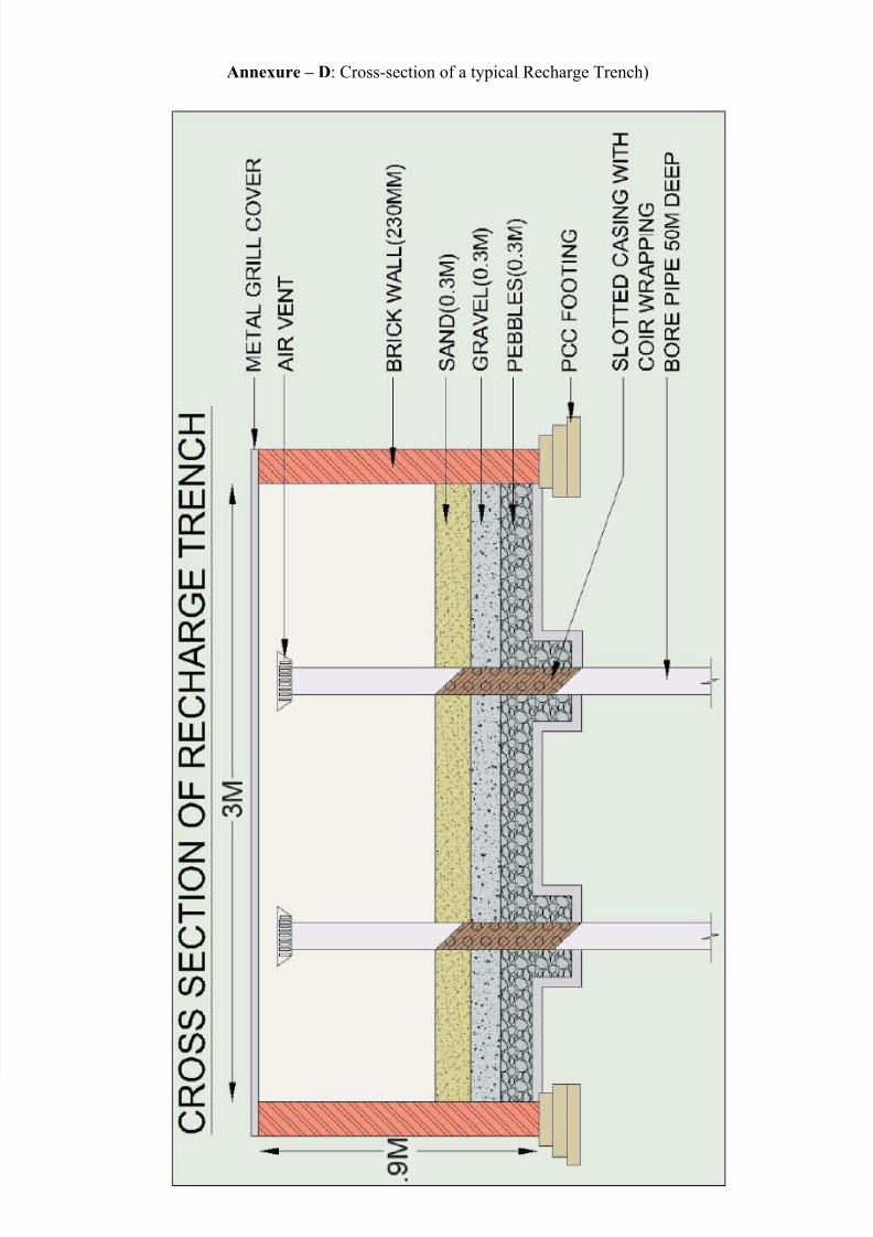
C. RECHARGE TRENCH (02 Nos.)
The specification for each trench (for gate A and B) should be 3m x 0.6m x 0.9m. There should
be two recharge bores of 150 mm diameter (6 inches) with maximum depth of 16 m.
(Please refer to Annexure –
D: Cross-section of a typical Recharge Trench)
It may be noted that the BOQ has been prepared items wise thus total quantities of items involved in
construction of all recharge structures have been mention instead of separate items for Recharge Well
/Recharge Trench /Desilting chamber.

7/21/2019 Addendum - RWH Design Specifications
http://slidepdf.com/reader/full/addendum-rwh-design-specifications 2/5
Annexure - A
LAYOUT MAP OF BHEL TOWNSHIP, NOIDA
DEPICTING POSITIONS OF RECHARGE WELLS & RECHARGE TRENCHES
LEGEND
1 TO 8 - RECHARGE WELLS (ALONG WITH DESILTING CHAMBER)
9 & 10 - RECHARGE TRENCHES

7/21/2019 Addendum - RWH Design Specifications
http://slidepdf.com/reader/full/addendum-rwh-design-specifications 3/5
Annexure – B: Cross-section of a typical Desilting Chamber

7/21/2019 Addendum - RWH Design Specifications
http://slidepdf.com/reader/full/addendum-rwh-design-specifications 4/5
Annexure – C: Cross-section of a typical Recharge Well
7/21/2019 Addendum - RWH Design Specifications
http://slidepdf.com/reader/full/addendum-rwh-design-specifications 5/5
Annexure – D: Cross-section of a typical Recharge Trench)