Embed Size (px)
Citation preview
DSPC PROJECT NO. 10-6103 ADDENDUM NO. 2 NEW CHIQUITA CHASSIS YARD PAGE 1 OF 14 REDEVELOPMENT OF THE LAFARGE ROCK STORAGE YARD
ADDENDUM N0. 2 Contract: DSPC Project No. 10-6103 Project: New Chiquita Chassis Yard
Redevelopment of the Lafarge Rock Storage Yard
Issue Date: May 4, 2016 Acknowledgement of Addendums � Vendors must acknowledge receipt of all Addendums on the Proposal Form in order for their Proposal
to be considered Responsive. Project Manual � Proposal Form
A revised Proposal Form is included as Attachment A to this Addendum No. 2. The Proposal Form is revised as follows:
� Lump Sum Base Bid Items
The following Lump Sum Base Bid Items are revised:
- Previous LS-7 Incoming Electrical Service is changed to LS-7 High Mast Light Foundations
- Previous LS-8 Power Distribution is changed to LS-8 Miscellaneous Concrete
Construction
The following Lump Sum Base Bid Items are added:
- LS-9 Incoming Electrical Service
- LS-10 Installation of Conduits for Power Distribution to Site Lighting and Refer Power Modules
- LS-11 High Mast Lighting

DSPC PROJECT NO. 10-6103 ADDENDUM NO. 2 NEW CHIQUITA CHASSIS YARD PAGE 2 OF 14 REDEVELOPMENT OF THE LAFARGE ROCK STORAGE YARD
� Unit Price Base Bid Items
The following Unit Price Base Bid Item is added with a specified Bid Quantity:
- UP-1 Undercut and Backfill
- UP-2 Offsite Disposal Soils Containing Gypsum Waste � Add Alternate Bid Items
The following Add Alternate Lump Sum Bid Item is added:
- AA-1 Refer Power Modules
� Specifications
New and revised Specification Sections are included in Attachment C to this Addendum No. 2. The new and revised Specification Sections are as follows:
� Section 260153, “Medium Voltage Cable”
ADD new Section in its entirety
� Section 260524, “Medium Voltage Grounding” ADD new Section in its entirety
� Section 261200, “Medium Voltage Transformers”
ADD new Section in its entirety
� Section 261301, “Medium Voltage Switchgear” ADD new Section in its entirety
� Section 3210150, “Pavement Markings”
REPLACE existing Section in its entirety. .
� Drawings
Revised Drawings are included in Attachment D to this Addendum No. 2. The revised Drawings are as follows:
� EL1.1
Replace existing Drawing with revised Drawing.
� E3.1 Replace existing Drawing with revised Drawing.

DSPC PROJECT NO. 10-6103 ADDENDUM NO. 2 NEW CHIQUITA CHASSIS YARD PAGE 3 OF 14 REDEVELOPMENT OF THE LAFARGE ROCK STORAGE YARD
� E3.3 Replace existing Drawing with revised Drawing.
� E4.1 Replace existing Drawing with revised Drawing.
� C13 Replace existing Drawing with revised Drawing.
Bidder Questions � Question
All excavation on this project needs to be removed and disposed off-site. The May 18, 2006 Geotechnical report has documented the existence of gypsum waste throughout the site and to various depths. Based on this report, it is clear that all of the excavated material will consist of gypsum waste material along with some crushed concrete that is mixed in the upper 18" of the site. The gypsum waste cannot be "source separated" in order to allow for a recycling option. The test pits also revealed a strong odor (hydrogen sulfide gas), which is typical of gypsum waste. The off-site disposal of such a large volume of gypsum waste presents a challenge to the bidders for several reasons: (a) the analytical data presented in the report may not be accepted by disposal facilities for actual disposal facility acceptance purposes; (b) the bid documents do not address the protocols and procedures that will be required of the Contractor in order to dispose of the gypsum waste; (c) more analytical testing will likely need to be performed by the Contractor but the bid proposal does not provide separate payment for these tests; (d) the bid documents have not characterized the gypsum waste for disposal purposes or for bidding purposes; (e) the bid proposal does not have a separate unit price pay item to pay per ton for the off-site disposal of the gypsum waste, which is customary practice when disposing of solid waste; (f) the project completion time of 90 days is not sufficient for the Contractor to perform additional testing and to obtain disposal facility acceptance; and, (g) as the generator of the waste, it is the responsibility of the owner to ensure that the gypsum waste is properly disposed, yet the bid documents do not address this important aspect of the project. Please clarify and address these items in an addendum as soon as possible.
□ Response
a. The Proposal Form has been modified to include a Lump Sum Add Alternate (AA-2) for
additional laboratory testing required to facilitate the Disposal of Soils Containing Gypsum Waste, All work associated with sampling and testing shall be arranged/performed by the Contractor, but will be paid for by the Owner under the Bid item AA-2
b. With respect to the handling and disposal of Soils Containing Gypsum Waste, Bidder shall prepare its Bid based on the following:

DSPC PROJECT NO. 10-6103 ADDENDUM NO. 2 NEW CHIQUITA CHASSIS YARD PAGE 4 OF 14 REDEVELOPMENT OF THE LAFARGE ROCK STORAGE YARD
� Basis of Bid
� For the purposes of the Bidder’s development of a cost for Bid Item LS-4, Bulk Excavation and Grading, Bidder shall assume that all materials excavated down to the specified subgrade shall be removed off-site with no “Special Disposal Requirements” (i.e., Hazardous Waste or Special Solid Waste).
� Bidder shall provide a Unit Cost Bid for disposal if the materials encountered during excavation are determined to be Soils Containing Gypsum Waste with “Special Disposal Requirements.” This cost is to be provided in Bid Item UP-2, Additional Cost for Disposal of Soils Containing Gypsum Waste. The Unit Price provided shall be the differential cost between disposal without “Special Disposal Requirements” and disposal with “Special Disposal Requirements.” A Bid Quantity is provided on the Bid Form. The actual cost paid for this Bid Item UP-2 will be adjusted up or down from the Bid Price based on the actual tonnage of material disposed of requiring “Special Disposal Requirements.”
� For the purposes of Bidder’s development of a cost for Bid Item UP-2, Bidder shall assume that any Soils Containing Gypsum Waste will be stockpiled on site until such time as a suitable disposal facility can be identified and all arrangements for disposal can be made.
� Contractor’s Responsibilities.
� Contractor shall be responsible for developing and implementing a Health and Safety
Plan for its employees and Subcontractors in the event Soils Containing Gypsum Waste are encountered.
� If Soils Containing Gypsum Wasted are encountered, it shall be the Contractor’s responsibility to determine if “Special Disposal Requirements” apply and to identify a suitable disposal facility that will accept the material.
� Owner’s Responsibilities.
� A stated above, if additional laboratory testing required to facilitate the Disposal of Soils Containing Gypsum Waste, all work associated with sampling and testing shall be arranged/performed by the Contractor, but will be paid for by the Owner under the Bid item LSAA-2
� Owner will retain and pay for any off-site (i.e., outside of the Limits of Disturbance) environmental monitoring required as a result of the Contractor encountering Soils Containing Gypsum Waste.
c. Refer to response a. above.
DSPC PROJECT NO. 10-6103 ADDENDUM NO. 2 NEW CHIQUITA CHASSIS YARD PAGE 5 OF 14 REDEVELOPMENT OF THE LAFARGE ROCK STORAGE YARD
d. The summary letter for the lab results prepared by Duffield Associates is attached. The full Environmental Report is available upon request to the successful Bidder.
e. The Proposal Form has been revised to include a Unit Price Base Bid Item (UP-2) and a Bid Quantity for the disposal of Soils Containing Gypsum Waste.
f. Refer to response to b. above. g. Refer to response to b. above.
� Question
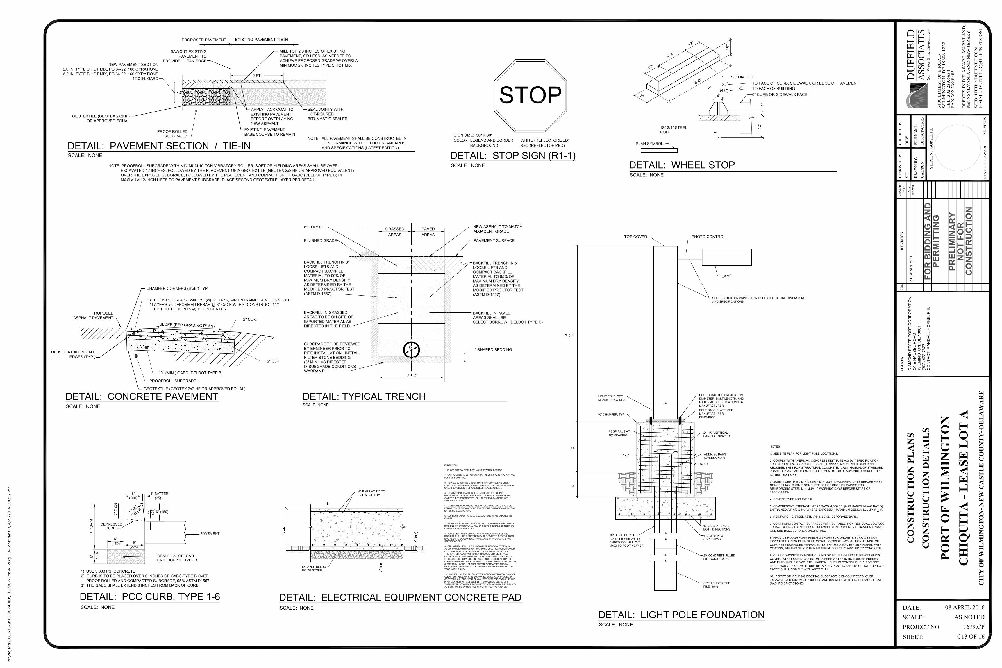
Drawing #C13 provides a Light Pole Foundation Detail that shows a pile-supported foundation for the new light poles. With regard to this detail please address and clarify the following items:
a. The detail on Drawing #C13 is missing dimensions. Please provide complete dimensions for the pile cap and the pedestal.
b. Please clarify the construction of the open-end pipe piles. For example, is the typical pile to be 30' long, with the upper 20 feet filled with concrete and the lower 10 feet un-filled? Or, is the typical pile to be 50' long, with the lower 30 feet un-filled, and the upper 20 feet filled with concrete?
c. Please provide a tip elevation for the piles. d. Please provide a design capacity for the piles. e. The pile detail does not show any dowels protruding from the top of the pile. Please
clarify. f. The bid documents do not provide any subsurface information that extends deep enough
to provide the bidders with information on the character and blow-counts for the material that will be encountered when driving the piles. Please provide this important information.
□ Response
a. Dimensions for the pile cap and pedestal are shown on Sheet C13 of 16, Revision No. 2 included in Attachment C to this Addendum No. 2.
b. The total length of the pile is thirty feet (30’) with the upper twenty feet (20’) filled with reinforced concrete and the lower ten feet (10’) unfilled. At Contractor’s option, the lower ten feet (10’) may be filled with non-reinforced concrete for ease of construction.
c. The tip elevation of the piles varies and is determined by the dimensions given in Detail: Light Pole Foundation on Sheet C13 of 16, Revision No. 2 included in Attachment C to this Addendum No. 2.
d. The pile design is controlled by lateral loading and, therefore, there is not a specified or required vertical pile capacity. Piles are to be of the material, diameter, thickness and length specified and are to be driven to the tip elevation determined by the dimensions given in Detail: Light Pole Foundation on Sheet C13 of 16, Revision No. 2 included in Attachment C to this Addendum No. 2.
e. Dowels protruding from the top of the pile into the pile cap/pier are shown on Sheet C13 of 16, Revision No. 2 included in Attachment C to this Addendum No. 2.
DSPC PROJECT NO. 10-6103 ADDENDUM NO. 2 NEW CHIQUITA CHASSIS YARD PAGE 6 OF 14 REDEVELOPMENT OF THE LAFARGE ROCK STORAGE YARD
f. Refer to response d. above. based on historical subsurface information and previous pile driving performed within the Port of Wilmington, piles will be driven into a very soft to soft high plasticity clay layer (N=Weight of Hammer) extending to a depth of greater than seventy feet (70’) below existing grade.
� Question
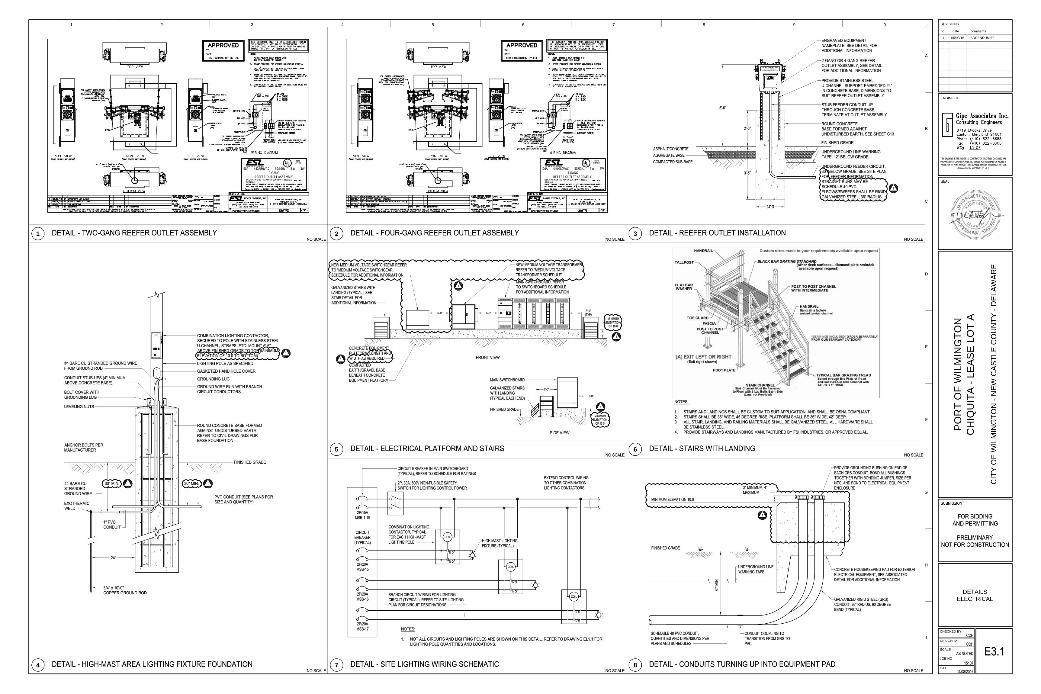
Drawing #E3.1 also provides a foundation detail for High Mast Area Lighting Fixtures. With regard to this detail please clarify the following:
a. Is this detail to be used for this project, and if so where? b. If this detail is to be used for this project, please provide complete dimensions for the drilled
shaft foundation, along with a tip elevation, compressive strength for the concrete, and the sizes and spacing of the steel reinforcement.
□ Response
a. Detail: High-Mast Area lighting Fixture Foundation on Drawing E3.1 should be used for installation of electrical components only (e.g., conduit installation, grounding installation, etc.). Drawing E3.1, Revision 1 is included in Attachment C to this Addendum No. 2. Structurally, the high mast light pole foundations shall be constructed as shown in Detail: Light Pole Foundation on Sheet C13 of 16, Revision No. 2 included in Attachment C to this Addendum No. 2.
b. Refer to response a. above
� Question
Drawing #C4 shows a Proposed Electric Equipment Slab near the northwest corner of the South Lot, and Drawing #E3.1 provides some conceptual information on the elevated slab. With regard to this Electric Equipment Slab please address and clarify the following:
a. The bid documents do not provide complete details and dimensions for the construction of
the elevated slab and its foundations. Please provide this missing information. b. The two access stairs and platforms need to be supported on a concrete slab or small
footings but none are shown on the drawings. Please provide this missing information. c. The drawings do not show a railing around the perimeter of the slab. Please clarify. d. Note #7 on Drawing #EP1.1 states that the concrete slab is to be 36" above finished
grade, but this height is not consistent with the height shown on the other drawings. Please clarify.
e. Detail #8 on Drawing #E3.1 shows a slab-on-grade for the Electrical Equipment Slab, which is not consistent with the other information provided for the Electrical Equipment Slab. Please clarify.
DSPC PROJECT NO. 10-6103 ADDENDUM NO. 2 NEW CHIQUITA CHASSIS YARD PAGE 7 OF 14 REDEVELOPMENT OF THE LAFARGE ROCK STORAGE YARD
f. The bid proposal does not provide a bid item for the Electrical Slab/Platform. Please revise the bid proposal to include a separate bid item for this work.
□ Response
a. A detail of the required construction has been added to Sheet C13 of 16, Revision No. 2 included in Attachment C to this Addendum No. 2.
b. The access stairs are each to be set on a 4” thick, 3’-0” by 3’-0” concrete slab placed on 4” Graded Aggregate Base.
c. A 42” high OSHA compliant, aluminum or galvanized steel railing will be required. d. The correct height for the top of the pad is 27” above finished grade. e. Refer to response to a. above. f. The Proposal Form has been revised and now includes a Lump Sum Bid Item; Item LS-8,
Miscellaneous Concrete Construction. The cost for equipment pads should be included in this Bid Item.
� Question
The plans show the construction of three reinforced concrete Dolly Pads, yet the bid proposal does not provide a separate bid item for the concrete Dolly Pads. Please revise the bid proposal to include a separate bid item for the concrete Dolly Pads.
□ Response
The Proposal Form has been revised and now includes a Lump Sum Bid Item; Item LS-8, Miscellaneous Concrete Construction. The cost for Chassis Leg Support Pads should be included in this Bid Item.
� Question
Drawing #C5 requires the Contractor to "wedge and level" a portion of the North Lot. With regard to this work, please clarify the following:
a. The drawings do not provide any details, dimensions, or thicknesses for this work. Please
provide this missing information. b. Please clarify the intent and definition of the term "wedge and level". c. Is the perimeter of the "wedge and level" area to be saw-cut? d. The bid proposal does not provide a separate pay item for this work. Please revise the bid
proposal to include a separate bid item for this work.
□ Response

DSPC PROJECT NO. 10-6103 ADDENDUM NO. 2 NEW CHIQUITA CHASSIS YARD PAGE 8 OF 14 REDEVELOPMENT OF THE LAFARGE ROCK STORAGE YARD
a. Adequate information is provided. Contractor is to wedge and level the existing pavement within the limits shown by placing asphalt overlay to the spot elevations (existing and proposed) shown on the Drawings.
b. Refer to response a. above. c. No saw-cutting is required. d. Include this work under LS-6, Paving.
� Question
Bid Item #LS-8 appears to have a typographical error. It currently reads: Power Distribution to Site Lighting and Site Lighting. We believe it should read: Power Distribution to Site Lighting and Reefer Outlets. Please clarify.
□ Response
The Proposal Form has been revised and the costs associated with power distribution to the High Mast Lighting and Refer Power Modules are now divided as follows:
� Power distribution to the High Mast Lighting is to be included under Item LS-11, High Mast Lighting.
� Power distribution to the Refer Power Modules is to be included under Item AA-1,
Refer Power Modules. � Question
The electrical drawings do not provide any typical details or locations for junction boxes/pull boxes for the underground conduits. Please clarify if these are required.
□ Response
Junction boxes/pull boxes will be required/permitted only as necessary for cable installation. Contractor shall submit required locations and details to Owner for review and approval prior to installation.
� Question
The electrical drawings do not provide a ductbank layout plan drawing that shows the conduit routing for the lighting circuits, the conduit for the power to the reefer outlets, and cross-references to the specific ductbank details that are to be used on Drawing #E3.2. Please provide this missing information.
DSPC PROJECT NO. 10-6103 ADDENDUM NO. 2 NEW CHIQUITA CHASSIS YARD PAGE 9 OF 14 REDEVELOPMENT OF THE LAFARGE ROCK STORAGE YARD
□ Response
The duct bank routing is now shown on Drawing EP1.1, Rev. 1 included in Attachment D to this Addendum No. 2.
� Question
Please clarify which party is responsible for performing the field-density testing and the testing of the fresh concrete and the breaking of concrete cylinders.
□ Response
All required testing services, except as noted below, will be arranged and paid for by Owner.
- Testing for the required gradation of concrete salvaged and crushed for reuse a Graded Aggregate base shall be arranged and paid for by Contractor.
- Testing required by Contractor’s Health and Safety Plan when excavating and handling Soils Contain Gypsum Waste shall be arranged and paid for by Contractor.
� Question
We do not believe that the 90-day completion time for this project is a reasonable or sufficient amount of time for the completion of this project when considering the following factors, all of which are beyond the control of the contractor: (a) the testing and disposal facility acceptance issues outlined above for the gypsum waste; (b) the long lead times for obtaining the electrical switchgear and high mast light poles after approval of shop drawings; and, (c) the upfront time period required for shop drawing submittals, reviews and approvals for the electrical gear and high mast light poles for this project. Based on prior experience, we believe that the project will require a minimum completion time of 180 calendar days in order to accommodate all of the above factors. Please clarify.
□ Response
It is required that, within the specified ninety (90) days, the construction be completed to the point where the facility can be put into active service for the movement and storage of chassis.
This requires that the following work items be completed:
DSPC PROJECT NO. 10-6103 ADDENDUM NO. 2 NEW CHIQUITA CHASSIS YARD PAGE 10 OF 14 REDEVELOPMENT OF THE LAFARGE ROCK STORAGE YARD
- Sediment and Erosion Control Measures; - Stormwater Management; - Bulk excavation and grading; - Placement of geotextile fabric and Graded Aggregate Base; - Paving of the new Chassis Yard including pavement marking; - High mast light foundations including foundation piles, reinforced concrete fill and
reinforced concrete caps and piers); - Miscellaneous Concrete Construction (Curbs, equipment pads within the main paved
area and chassis leg support pads and refer plug pedestals, etc.); and - Installation of conduits for power distribution to site lighting and Refer Power Modules
The following items may be completed after the specified ninety (90) days:
- Pavement patching and pavement overlays outside of the footprint of the new Chassis Yard;
- Incoming electrical service; - High mast lighting including power distribution, poles and fixtures; - Disposal of stockpiled Soils Containing Gypsum Waste; and - Installation of Refer Power Modules including power distribution to Refer Power
Modules. With respect to Project Schedule requirements, Bidders are reminded that the Owner will impose no limitations on the Contractor with respect to work hours. The site will be available to the Contractor twenty four (24) hours per day, seven (7) days per week.
� Question
All of the duct bank details shown on Drawing #E3.2 are for direct buried installations. Yet, the Duct Bank Spec Section #260543 appears to require concrete encased duct banks. Please clarify whether or not the duct banks are to be concrete encased. If so, then please provide a typical concrete encased duct bank detail.
□ Response
Conduits are to be direct-buried as shown in the Drawing Details.
� Question
Please clarify the following electrical items.

DSPC PROJECT NO. 10-6103 ADDENDUM NO. 2 NEW CHIQUITA CHASSIS YARD PAGE 11 OF 14 REDEVELOPMENT OF THE LAFARGE ROCK STORAGE YARD
a. Drawing #EL1.1 shows the existing meter, switch and riser pole that are to be abandoned. Please confirm our assumption that DPL is responsible for the removal and disposal of these abandoned items.
b. While Drawing #EL1.1 shows the existing meter, switch and pole that are to be abandoned, the drawing does not show the location of the new feeder, the size of the new feeder cable, and the size of the feeder conduit.
c. Is DPL furnishing and installing the new feeder to the line-side of the transformer? d. Please clarify what DPL is furnishing and installing, when this will be done and who is
responsible for coordinating with DPL. e. Please confirm our assumption that the DSPC will be responsible to pay any fees to DPL, as
well as the cost of the electrical permit and the electrical inspection costs for this project.
□ Response
a. The existing metering cubicle and switch are to remain. The riser pole will be removed by DPL. Contractor shall be responsible for coordination with DPL.
b. New feeder cable and conduit information is provided in the revised Drawings included in Attachment C to this Addendum No. 2.
c. DPL will provide new metering cubicle. Contractor shall provide new medium voltage isolation switchgear including feeder from metering cubicle to switchgear, and new medium voltage transformer including feeder from new switchgear to transformer. Detailed information is provided in the revised Drawings included in Attachment C to this Addendum No. 2. Contractor shall be responsible for coordination with DPL.
d. DPL will provide new metering cubicle. Contractor shall provide new medium voltage isolation switchgear including feeder from metering cubicle to switchgear, and new medium voltage transformer including feeder from new switchgear to transformer. Detailed information is provided in the revised Drawings included in Attachment C to this Addendum No. 2.
e. Contractor shall pay and Owner will reimburse Contractor for costs from DPL. Contractor shall obtain permits and pay electrical permit costs and inspection costs.
� Question
Kyle Conti Construction is a planholder for the above referenced project, and we attended the mandatory Pre-Bid Meeting held on April 15th. Please note that the set of drawings issued for this project was supposed to include Sheet E3.4 and Sheet E5.1, but those two Electrical drawings were not included in the set of drawings that were downloaded from the website. Please provide these two missing Electrical drawings as quickly as possible.
□ Response
These Drawings were incorrectly listed on the Index of Sheets on the original issue of Drawing C1 of 16 / SWM 1 of 10. These Drawings do not exist.
DSPC PROJECT NO. 10-6103 ADDENDUM NO. 2 NEW CHIQUITA CHASSIS YARD PAGE 12 OF 14 REDEVELOPMENT OF THE LAFARGE ROCK STORAGE YARD
� Question
. . . . is there a Division 26 Section for "Exterior Lighting"? This section is mentioned at the top of page 260923-3.
□ Response
There is no Division 26 Section for "Exterior Lighting.” The specification of exterior lighting is provided on the Drawings
� Question
We received and reviewed Addendum #1 for the above referenced project and wish to point out the following items that require further clarification. a. The Addendum Q&A'S did not provide a Response that addresses the issues with the
completion time. Please address this important issue as soon as possible. b. The Response to the Question pertaining to the lack of details for the Trench Drain needs
further clarification. Please add the following details to the bidding documents � Please provide a typical cross section through the Trench Drain indicating the type and
thickness of any stone bedding, and indicate if any concrete encasement is required. � Also, please provide a detail for joining the 12" storm drain pipe with the trench drain.
c. The Addendum #1 drawings did not provide "clouds" or other symbols to indicate what was changed on the new drawings, which is customary practice when making revisions to drawings. The lack of "clouded" revisions makes it very difficult to find the revisions. Therefore, we request that all revisions be "clouded" so that the changed information can be readily identified. For example we cannot determine what was changed on the following drawings: Dwg C-3, C-6, C-8 & C-15.
□ Response
a. Refer to the response above for information responding to the issues with the completion
time.
b. Follow the manufacturer’s recommendations for bedding and construction of the pipe to drain connection. Contractor shall submit Shop Drawings to Owner for approval prior to ordering materials.
c. Descriptions of changes for C Drawings were included as text with the Addendum, with no clouds shown. The Drawings have not been approved by DNREC as of this writing. Therefore, clouds cannot be shown.

DSPC PROJECT NO. 10-6103 ADDENDUM NO. 2 NEW CHIQUITA CHASSIS YARD PAGE 13 OF 14 REDEVELOPMENT OF THE LAFARGE ROCK STORAGE YARD
� Question
Federal wage rates were not included in Addendum #1.
□ Response
The Federal Wage Rate Schedule is included in Attachment B to this Addendum No. 2. � Question
… there are several questions that were asked at the pre-bid meeting that were to be answered in addendum #1, however they were not. Will there be another addendum with answers to the pre-bid meeting questions? Specifically the questions are regarding;
1. The inclusion of the Federal rate schedule 2. The Earthwork specification references to Unforeseen conditions and Unsuitable
Excavated Materials 3. The type of paint to be used for line striping
□ Response
1. The Federal Wage Rate Schedule is included in Attachment B to this Addendum No. 2. 2. As indicated in the response to the first question above, for the purposes of the Bidder’s
development of a cost for Bid Item LS-4, Bulk Excavation and Grading, Bidder shall assume that all materials excavated down to the specified subgrade shall be removed off-site with no “Special Disposal Requirements” (i.e., Hazardous Waste or Special Solid Waste). If Soils Containing Gypsum Waste are encountered, disposal of the materials will be dealt with as described above.
With respect to Unsuitable Excavated Materials beyond the limits of the specified subgrade, the Bid Form has been revised to include a Bid Item (UP-1) for the undercut and backfill of unsuitable soils. For the purposes of the Bidder’s development of a cost for Bid Item UP-1. Undercut and Backfill of Unsuitable Soils, Bidder shall assume the following:
Undercut and Backfill of Unsuitable Soils includes: - Excavation of the unsuitable soils;
DSPC PROJECT NO. 10-6103 ADDENDUM NO. 2 NEW CHIQUITA CHASSIS YARD PAGE 14 OF 14 REDEVELOPMENT OF THE LAFARGE ROCK STORAGE YARD
- Offsite disposal of the excavated materials without “Special Disposal Requirements”;
- Lining of the excavation with a geotextile filter fabric; and - Backfill with No. 57 Stone.
If the excavated soils are determined to be Soils Containing Gypsum Waste, the disposal of the materials will be paid for in accordance with UP-2 described above.
3. Refer to revised Specification Section 3210150, “Pavement Markings” included in Attachment D to this Addendum No. 2
� Question
Based on the information contained in the Geotechnical Report the material to be excavated from the New Chiquita Chassis Yard contains gypsum waste intermingled with crushed concrete. Based on a conversation with the Cherry Island Landfill the excavated material from the New Chiquita Chassis Yard will be regarded as a Special Waste and the tipping fee would be $88.50 per ton. The excavated material cannot be accepted as cover soil without a lengthy review and approval period that would require the submittal of analytical data. We were also informed that the review period for cover soil approval would take several months to complete, at best.
We were also referred to the attached waste disposal guidance document that generators of solid waste need to follow in order to obtain disposal facility acceptance for Special Waste. The generator of special waste needs to provide analytical data to the landfill for facility acceptance. It was also pointed out that if the excavated material contains a high proportion of gypsum, then that will create off-gas and odor problems that may cause the excavated material to be rejected by the landfill facility.
Therefore, please issue guidance to the bidders regarding the off-site disposal of the excavated materials.
□ Response
Refer to the response to the first question above.
END OF ADDENDUM
ADDENDUM N0. 2
Contract: DSPC Project No. 10-6103
NEW CHIQUITA CHASSIS YARD REDEVELOPMENT OF THE LAFARGE ROCK STORAGE YARD
Issue Date: May 4, 2016
ATTACHMENT A REVISED PROPOSAL FORM

DSPC PROJECT NO. 10-6103 PROPOSAL NEW CHIQUITA CHASSIS YARD PAGE P-1 OF 11 REDEVELOPMENT OF THE LAFARGE ROCK STORAGE YARD REVISION 1 – ADDENDUM 2
PROPOSAL
DIAMOND STATE PORT CORPORATION PORT OF WILMINGTON
DSPC PROJECT NO. 10-6103
NEW CHIQUITA CHASSIS YARD REDEVELOPMENT OF THE LAFARGE ROCK STORAGE YARD
Submitted To: Randall M. Horne, P.E. Director, Engineering & Maintenance
Diamond State Port Corporation Port of Wilmington 1 Hausel Road Wilmington, Delaware 19801 Submitted By:
(Name of Bidder)
(Address of Bidder) (Telephone Number of Bidder) Dear Sir: We, (Name of Bidder) have received the Bidding Documents for the subject project, including the Invitation to Bid, Instructions to Bidders, General Conditions, Special Conditions, and the Drawings and Specifications included in the Project Manual. We have also received the Addenda acknowledged below and have included their provisions in our Bid. We have examined the Bidding Documents and the premises and submit the following bid to perform all required work: BID Base Bid –
Lump Sum Base Bids -
Item LS-1 Mobilization/Demobilization Price $ ( ) In words

DSPC PROJECT NO. 10-6103 PROPOSAL NEW CHIQUITA CHASSIS YARD PAGE P-2 OF 11 REDEVELOPMENT OF THE LAFARGE ROCK STORAGE YARD REVISION 1 – ADDENDUM 2
Item LS-2 Sediment and Erosion Control Measures Price $ ( ) In words Item LS-3 Stormwater Management Price $ ( ) In words Item LS-4 Bulk Excavation and Grading Price $ ( ) In words Item LS-5 Geotextile Fabric and Graded Aggregate Base Price $ ( ) In words Item LS-6 Paving (Including Pavement Patching, Pavement Overlays and Pavement Marking) Price $ ( ) In words Item LS-7 High Mast Light Foundations (Including Foundation Piles, Reinforced Concrete Fill and Reinforced Concrete Caps and Piers) Price $ ( ) In words Item LS-8 Miscellaneous Concrete Construction (Curbs, Equipment Pads, Chassis Leg Support Pads, And Refer Plug Pedestals, etc.) Price $ ( ) In words
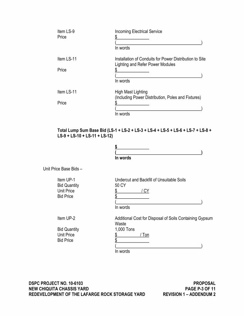
DSPC PROJECT NO. 10-6103 PROPOSAL NEW CHIQUITA CHASSIS YARD PAGE P-3 OF 11 REDEVELOPMENT OF THE LAFARGE ROCK STORAGE YARD REVISION 1 – ADDENDUM 2
Item LS-9 Incoming Electrical Service Price $ ( ) In words
Item LS-11 Installation of Conduits for Power Distribution to Site Lighting and Refer Power Modules Price $ ( ) In words
Item LS-11 High Mast Lighting (Including Power Distribution, Poles and Fixtures) Price $ ( ) In words
Total Lump Sum Base Bid (LS-1 + LS-2 + LS-3 + LS-4 + LS-5 + LS-6 + LS-7 + LS-8 + LS-9 + LS-10 + LS-11 + LS-12) $ ( ) In words
Unit Price Base Bids –
Item UP-1 Undercut and Backfill of Unsuitable Soils Bid Quantity 50 CY Unit Price $ / CY Bid Price $ ( ) In words Item UP-2 Additional Cost for Disposal of Soils Containing Gypsum Waste Bid Quantity 1,000 Tons Unit Price $ / Ton Bid Price $ ( ) In words

DSPC PROJECT NO. 10-6103 PROPOSAL NEW CHIQUITA CHASSIS YARD PAGE P-4 OF 11 REDEVELOPMENT OF THE LAFARGE ROCK STORAGE YARD REVISION 1 – ADDENDUM 2
Total Unit Price Base Bid (UP-1) $ ( ) In words
Total Base Bid (Total Lump Sum Base Bid + Total Unit Price Base Bid) $ ( ) In words
Alternate Bids –
Add Alternate Bids
Item AA-1 Refer Power Modules (Including Power Distribution to Refer Modules and providing and installing Reefer Power Modules Price $ LS ( ) In words
Item AA-2 Additional laboratory testing required to facilitate the disposal of Soils Containing Gypsum Waste Price $ LS ( ) In words
DSPC PROJECT NO. 10-6103 PROPOSAL NEW CHIQUITA CHASSIS YARD PAGE P-5 OF 11 REDEVELOPMENT OF THE LAFARGE ROCK STORAGE YARD REVISION 1 – ADDENDUM 2
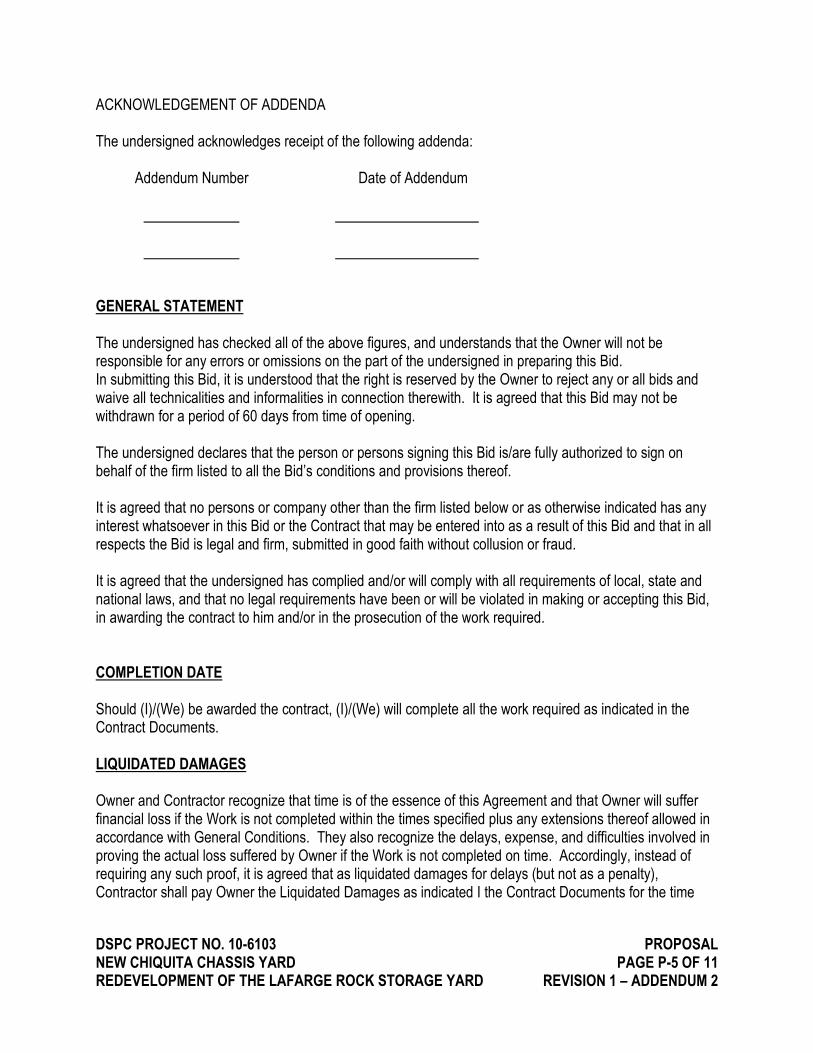
ACKNOWLEDGEMENT OF ADDENDA The undersigned acknowledges receipt of the following addenda: Addendum Number Date of Addendum GENERAL STATEMENT The undersigned has checked all of the above figures, and understands that the Owner will not be responsible for any errors or omissions on the part of the undersigned in preparing this Bid. In submitting this Bid, it is understood that the right is reserved by the Owner to reject any or all bids and waive all technicalities and informalities in connection therewith. It is agreed that this Bid may not be withdrawn for a period of 60 days from time of opening. The undersigned declares that the person or persons signing this Bid is/are fully authorized to sign on behalf of the firm listed to all the Bid’s conditions and provisions thereof. It is agreed that no persons or company other than the firm listed below or as otherwise indicated has any interest whatsoever in this Bid or the Contract that may be entered into as a result of this Bid and that in all respects the Bid is legal and firm, submitted in good faith without collusion or fraud. It is agreed that the undersigned has complied and/or will comply with all requirements of local, state and national laws, and that no legal requirements have been or will be violated in making or accepting this Bid, in awarding the contract to him and/or in the prosecution of the work required. COMPLETION DATE Should (I)/(We) be awarded the contract, (I)/(We) will complete all the work required as indicated in the Contract Documents. LIQUIDATED DAMAGES Owner and Contractor recognize that time is of the essence of this Agreement and that Owner will suffer financial loss if the Work is not completed within the times specified plus any extensions thereof allowed in accordance with General Conditions. They also recognize the delays, expense, and difficulties involved in proving the actual loss suffered by Owner if the Work is not completed on time. Accordingly, instead of requiring any such proof, it is agreed that as liquidated damages for delays (but not as a penalty), Contractor shall pay Owner the Liquidated Damages as indicated I the Contract Documents for the time

DSPC PROJECT NO. 10-6103 PROPOSAL NEW CHIQUITA CHASSIS YARD PAGE P-6 OF 11 REDEVELOPMENT OF THE LAFARGE ROCK STORAGE YARD REVISION 1 – ADDENDUM 2
worked after the time specified for Substantial Completion until the Work is substantially complete. After Substantial Completion, if Contractor shall neglect, refuse, or fail to complete the remaining Work within the time specified for completion and readiness for final payment or any proper extension thereof granted by Owner, Contractor shall pay Owner the Liquidated Damages as indicated in the Contract Documents for each day that expires after the time specified for completion and readiness for final payment. CANCELLATION OF CONTRACT With the acceptance of this contract, it is to be understood and agreed that should this project be stopped for any valid reason by the Owner, the cost of all work completed to date and any materials which cannot be returned for credit or have been ordered and cannot be cancelled will be paid in full. Contractor shall be entitled to a fee applied to the cost of the work and materials completed at the time of the notice of cancellation as determined by the owner. All materials purchased from the Subcontractor shall become the property of the Owner and shall be delivered to the job site. We have attached the required Bid Bond, Consent of Surety, Non-Collusion Statement, Equal Opportunity Statement, and Subcontractor Listing to this bid. Respectfully submitted, Signature when Bidder is an individual:
(Date) (Firm Name)
(Owner) Signature when bidder is a partnership:
(Date) (Firm Name)
(Signature of Partner) (Signature of Partner) (Signature of Partner)
DSPC PROJECT NO. 10-6103 PROPOSAL NEW CHIQUITA CHASSIS YARD PAGE P-7 OF 11 REDEVELOPMENT OF THE LAFARGE ROCK STORAGE YARD REVISION 1 – ADDENDUM 2
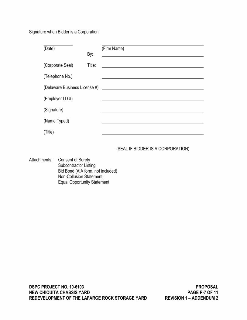
Signature when Bidder is a Corporation:
(Date) (Firm Name)
By:
(Corporate Seal) Title:
(Telephone No.)
(Delaware Business License #)
(Employer I.D.#)
(Signature)
(Name Typed)
(Title) (SEAL IF BIDDER IS A CORPORATION) Attachments: Consent of Surety Subcontractor Listing Bid Bond (AIA form, not included) Non-Collusion Statement Equal Opportunity Statement

DSPC PROJECT NO. 10-6103 PROPOSAL NEW CHIQUITA CHASSIS YARD PAGE P-8 OF 11 REDEVELOPMENT OF THE LAFARGE ROCK STORAGE YARD REVISION 1 – ADDENDUM 2
NON-COLLUSION STATEMENT
Gentlemen: This is to certify that the undersigned Bidder has not, either directly or indirectly, entered into any agreement, participated in any collusion, or otherwise engaged in any illegal activities in the process of securing this Contract (DSPC Contract No. 10-6103; New Chiquita Chassis Yard, Redevelopment of the Lafarge Rock Storage Yard) with the Diamond State Port Corporation. BY: (Signature of Bidder) Corporate Seal Attest: Secretary SWORN to and SUBSCRIBED before me this day of , 20 . My Commission Expires: Notary Public
DSPC PROJECT NO. 10-6103 PROPOSAL NEW CHIQUITA CHASSIS YARD PAGE P-9 OF 11 REDEVELOPMENT OF THE LAFARGE ROCK STORAGE YARD REVISION 1 – ADDENDUM 2
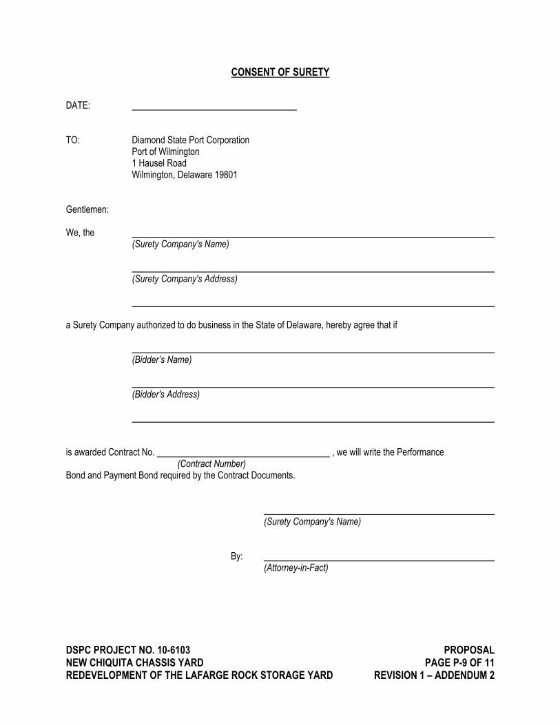
CONSENT OF SURETY
DATE: TO: Diamond State Port Corporation Port of Wilmington 1 Hausel Road Wilmington, Delaware 19801 Gentlemen: We, the (Surety Company's Name) (Surety Company's Address)
a Surety Company authorized to do business in the State of Delaware, hereby agree that if (Bidder’s Name) (Bidder's Address) is awarded Contract No. , we will write the Performance (Contract Number) Bond and Payment Bond required by the Contract Documents. (Surety Company's Name) By: (Attorney-in-Fact)

DSPC PROJECT NO. 10-6103 PROPOSAL NEW CHIQUITA CHASSIS YARD PAGE P-10 OF 11 REDEVELOPMENT OF THE LAFARGE ROCK STORAGE YARD REVISION 1 – ADDENDUM 2
SUBCONTRACTOR LISTING
If awarded this Contact, we, , (name of Bidder) will award subcontracts to the following subcontractors. Where we intend to perform the work with our own forces, our name is listed as subcontractor.
CONTRACTOR NAME AND ADDRESS DE BUSINESS NO.
Earthwork Paving Concrete Electrical
DSPC PROJECT NO. 10-6103 PROPOSAL NEW CHIQUITA CHASSIS YARD PAGE P-11 OF 11 REDEVELOPMENT OF THE LAFARGE ROCK STORAGE YARD REVISION 1 – ADDENDUM 2
REQUIREMENTS FOR SUBMITTAL OF THE
EQUALITY OPPORTUNITY STATEMENT
“During the performance of this contract, the Contractor agrees as follows”
“The Contractor will not discriminate against any employee or applicant for employment because of race, creed, color, sex or natural origin. The Contractor will take affirmative action to ensure that applicants are employed, and that employees are treated during employment, without regard to their race, creed, color, sex or national origin. Such action shall include, but not be limited to, the following: Employment, upgrading, demotion or transfer; recruitment or recruitment advertising; layoff or termination; rates of pay or other forms of compensation; and selection for training, including apprenticeship. The Contractor agrees to post in conspicuous places available to employees and applicants for employment notices to be provided by the contracting agency setting forth the provisions of this nondiscrimination clause.
The Contractor will, in all solicitations or advertisements for employees placed by or on behalf of the Contractor, state that all qualified applicants will receive consideration for employment without regard to race, creed, color, sex or national origin.”
(Contractor’s Name)
(Contractor’s Address)
(Authorized Representative)
(Signature)
(Date)

ADDENDUM N0. 2
Contract: DSPC Project No. 10-6103
NEW CHIQUITA CHASSIS YARD REDEVELOPMENT OF THE LAFARGE ROCK STORAGE YARD
Issue Date: May 4, 2016
ATTACHMENT B FEDERAL PREVAILING WAGE RATE SCHEDULE
HEAVY CONSTRUCTION
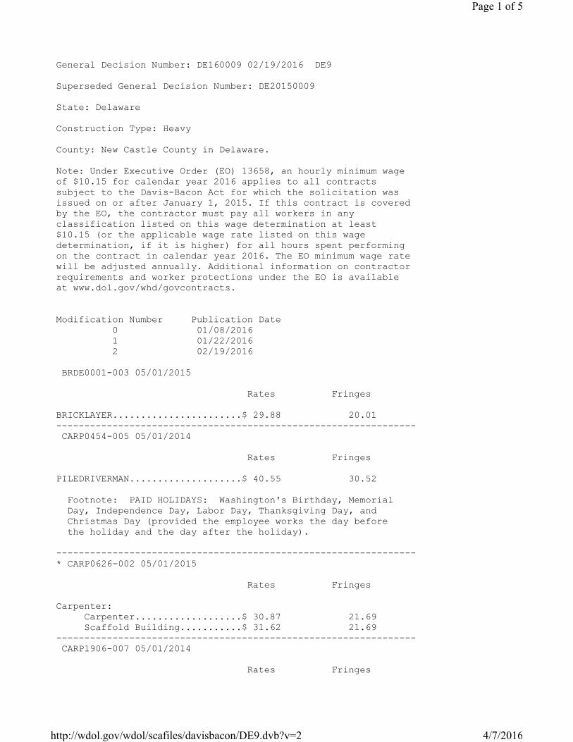
General Decision Number: DE160009 02/19/2016 DE9
Superseded General Decision Number: DE20150009
State: Delaware
Construction Type: Heavy
County: New Castle County in Delaware.
Note: Under Executive Order (EO) 13658, an hourly minimum wage
of $10.15 for calendar year 2016 applies to all contracts
subject to the Davis-Bacon Act for which the solicitation was
issued on or after January 1, 2015. If this contract is covered
by the EO, the contractor must pay all workers in any
classification listed on this wage determination at least
$10.15 (or the applicable wage rate listed on this wage
determination, if it is higher) for all hours spent performing
on the contract in calendar year 2016. The EO minimum wage rate
will be adjusted annually. Additional information on contractor
requirements and worker protections under the EO is available
at www.dol.gov/whd/govcontracts.
Modification Number Publication Date
0 01/08/2016
1 01/22/2016
2 02/19/2016
BRDE0001-003 05/01/2015
Rates Fringes
BRICKLAYER.......................$ 29.88 20.01
----------------------------------------------------------------
CARP0454-005 05/01/2014
Rates Fringes
PILEDRIVERMAN....................$ 40.55 30.52
Footnote: PAID HOLIDAYS: Washington's Birthday, Memorial
Day, Independence Day, Labor Day, Thanksgiving Day, and
Christmas Day (provided the employee works the day before
the holiday and the day after the holiday).
----------------------------------------------------------------
* CARP0626-002 05/01/2015
Rates Fringes
Carpenter:
Carpenter...................$ 30.87 21.69
Scaffold Building...........$ 31.62 21.69
----------------------------------------------------------------
CARP1906-007 05/01/2014
Rates Fringes
Page 1 of 5
4/7/2016http://wdol.gov/wdol/scafiles/davisbacon/DE9.dvb?v=2
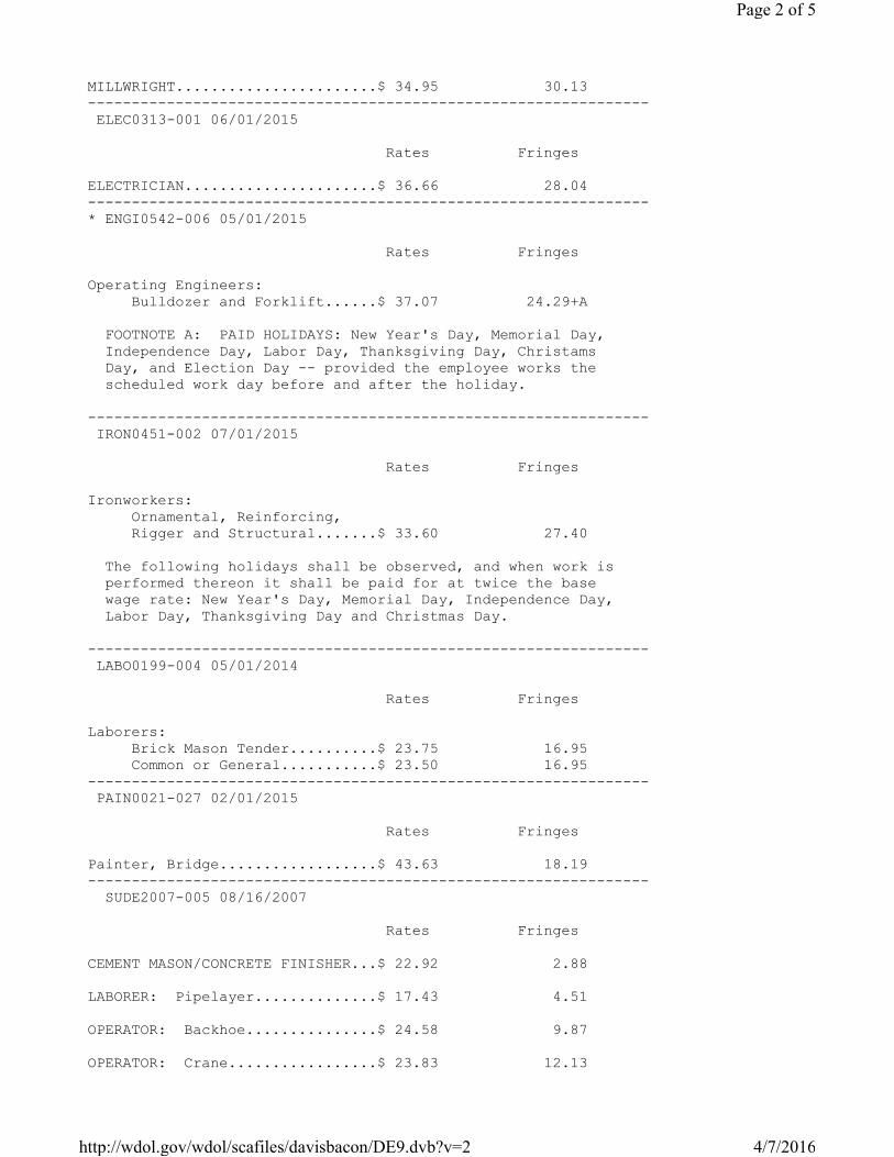
MILLWRIGHT.......................$ 34.95 30.13
----------------------------------------------------------------
ELEC0313-001 06/01/2015
Rates Fringes
ELECTRICIAN......................$ 36.66 28.04
----------------------------------------------------------------
* ENGI0542-006 05/01/2015
Rates Fringes
Operating Engineers:
Bulldozer and Forklift......$ 37.07 24.29+A
FOOTNOTE A: PAID HOLIDAYS: New Year's Day, Memorial Day,
Independence Day, Labor Day, Thanksgiving Day, Christams
Day, and Election Day -- provided the employee works the
scheduled work day before and after the holiday.
----------------------------------------------------------------
IRON0451-002 07/01/2015
Rates Fringes
Ironworkers:
Ornamental, Reinforcing,
Rigger and Structural.......$ 33.60 27.40
The following holidays shall be observed, and when work is
performed thereon it shall be paid for at twice the base
wage rate: New Year's Day, Memorial Day, Independence Day,
Labor Day, Thanksgiving Day and Christmas Day.
----------------------------------------------------------------
LABO0199-004 05/01/2014
Rates Fringes
Laborers:
Brick Mason Tender..........$ 23.75 16.95
Common or General...........$ 23.50 16.95
----------------------------------------------------------------
PAIN0021-027 02/01/2015
Rates Fringes
Painter, Bridge..................$ 43.63 18.19
----------------------------------------------------------------
SUDE2007-005 08/16/2007
Rates Fringes
CEMENT MASON/CONCRETE FINISHER...$ 22.92 2.88
LABORER: Pipelayer..............$ 17.43 4.51
OPERATOR: Backhoe...............$ 24.58 9.87
OPERATOR: Crane.................$ 23.83 12.13
Page 2 of 5
4/7/2016http://wdol.gov/wdol/scafiles/davisbacon/DE9.dvb?v=2
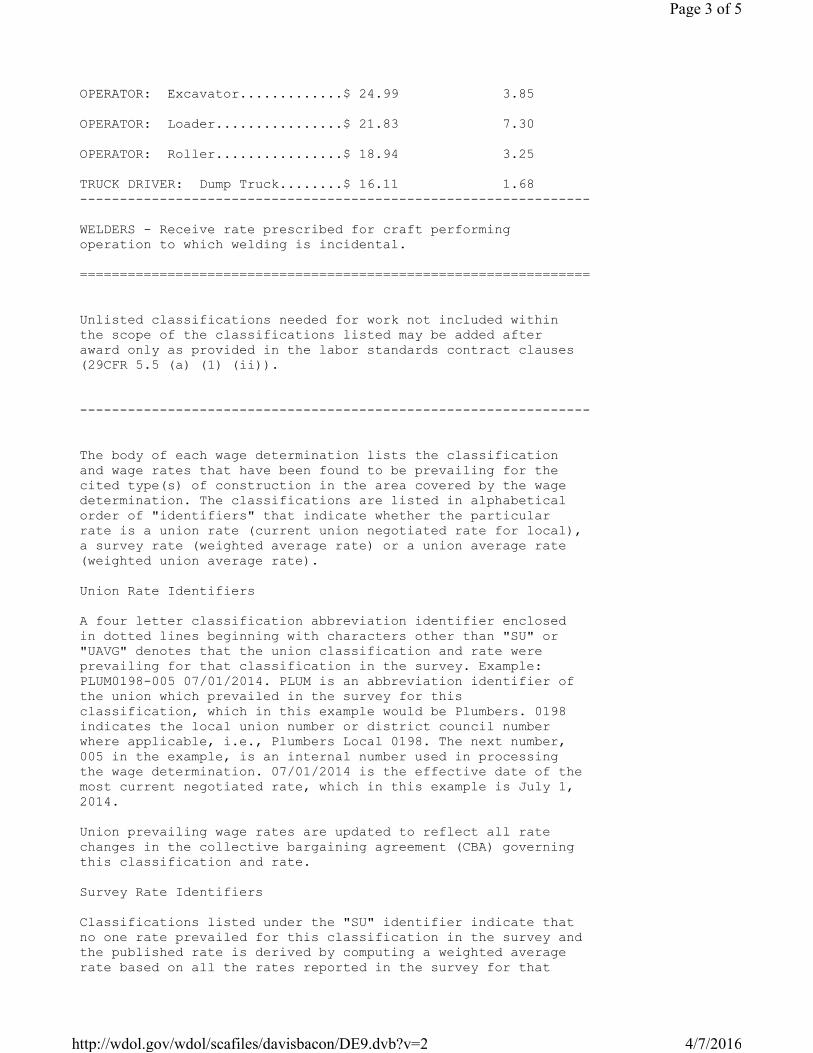
OPERATOR: Excavator.............$ 24.99 3.85
OPERATOR: Loader................$ 21.83 7.30
OPERATOR: Roller................$ 18.94 3.25
TRUCK DRIVER: Dump Truck........$ 16.11 1.68
----------------------------------------------------------------
WELDERS - Receive rate prescribed for craft performing
operation to which welding is incidental.
================================================================
Unlisted classifications needed for work not included within
the scope of the classifications listed may be added after
award only as provided in the labor standards contract clauses
(29CFR 5.5 (a) (1) (ii)).
----------------------------------------------------------------
The body of each wage determination lists the classification
and wage rates that have been found to be prevailing for the
cited type(s) of construction in the area covered by the wage
determination. The classifications are listed in alphabetical
order of "identifiers" that indicate whether the particular
rate is a union rate (current union negotiated rate for local),
a survey rate (weighted average rate) or a union average rate
(weighted union average rate).
Union Rate Identifiers
A four letter classification abbreviation identifier enclosed
in dotted lines beginning with characters other than "SU" or
"UAVG" denotes that the union classification and rate were
prevailing for that classification in the survey. Example:
PLUM0198-005 07/01/2014. PLUM is an abbreviation identifier of
the union which prevailed in the survey for this
classification, which in this example would be Plumbers. 0198
indicates the local union number or district council number
where applicable, i.e., Plumbers Local 0198. The next number,
005 in the example, is an internal number used in processing
the wage determination. 07/01/2014 is the effective date of the
most current negotiated rate, which in this example is July 1,
2014.
Union prevailing wage rates are updated to reflect all rate
changes in the collective bargaining agreement (CBA) governing
this classification and rate.
Survey Rate Identifiers
Classifications listed under the "SU" identifier indicate that
no one rate prevailed for this classification in the survey and
the published rate is derived by computing a weighted average
rate based on all the rates reported in the survey for that
Page 3 of 5
4/7/2016http://wdol.gov/wdol/scafiles/davisbacon/DE9.dvb?v=2
classification. As this weighted average rate includes all
rates reported in the survey, it may include both union and
non-union rates. Example: SULA2012-007 5/13/2014. SU indicates
the rates are survey rates based on a weighted average
calculation of rates and are not majority rates. LA indicates
the State of Louisiana. 2012 is the year of survey on which
these classifications and rates are based. The next number, 007
in the example, is an internal number used in producing the
wage determination. 5/13/2014 indicates the survey completion
date for the classifications and rates under that identifier.
Survey wage rates are not updated and remain in effect until a
new survey is conducted.
Union Average Rate Identifiers
Classification(s) listed under the UAVG identifier indicate
that no single majority rate prevailed for those
classifications; however, 100% of the data reported for the
classifications was union data. EXAMPLE: UAVG-OH-0010
08/29/2014. UAVG indicates that the rate is a weighted union
average rate. OH indicates the state. The next number, 0010 in
the example, is an internal number used in producing the wage
determination. 08/29/2014 indicates the survey completion date
for the classifications and rates under that identifier.
A UAVG rate will be updated once a year, usually in January of
each year, to reflect a weighted average of the current
negotiated/CBA rate of the union locals from which the rate is
based.
----------------------------------------------------------------
WAGE DETERMINATION APPEALS PROCESS
1.) Has there been an initial decision in the matter? This can
be:
* an existing published wage determination
* a survey underlying a wage determination
* a Wage and Hour Division letter setting forth a position on
a wage determination matter
* a conformance (additional classification and rate) ruling
On survey related matters, initial contact, including requests
for summaries of surveys, should be with the Wage and Hour
Regional Office for the area in which the survey was conducted
because those Regional Offices have responsibility for the
Davis-Bacon survey program. If the response from this initial
contact is not satisfactory, then the process described in 2.)
and 3.) should be followed.
With regard to any other matter not yet ripe for the formal
process described here, initial contact should be with the
Branch of Construction Wage Determinations. Write to:
Branch of Construction Wage Determinations
Wage and Hour Division
Page 4 of 5
4/7/2016http://wdol.gov/wdol/scafiles/davisbacon/DE9.dvb?v=2
U.S. Department of Labor
200 Constitution Avenue, N.W.
Washington, DC 20210
2.) If the answer to the question in 1.) is yes, then an
interested party (those affected by the action) can request
review and reconsideration from the Wage and Hour Administrator
(See 29 CFR Part 1.8 and 29 CFR Part 7). Write to:
Wage and Hour Administrator
U.S. Department of Labor
200 Constitution Avenue, N.W.
Washington, DC 20210
The request should be accompanied by a full statement of the
interested party's position and by any information (wage
payment data, project description, area practice material,
etc.) that the requestor considers relevant to the issue.
3.) If the decision of the Administrator is not favorable, an
interested party may appeal directly to the Administrative
Review Board (formerly the Wage Appeals Board). Write to:
Administrative Review Board
U.S. Department of Labor
200 Constitution Avenue, N.W.
Washington, DC 20210
4.) All decisions by the Administrative Review Board are final.
================================================================
END OF GENERAL DECISION
Page 5 of 5
4/7/2016http://wdol.gov/wdol/scafiles/davisbacon/DE9.dvb?v=2
ADDENDUM N0. 2
Contract: DSPC Project No. 10-6103
NEW CHIQUITA CHASSIS YARD REDEVELOPMENT OF THE LAFARGE ROCK STORAGE YARD
Issue Date: May 4, 2016
ATTACHMENT C REVISED DRAWINGS

SSSS
SSSS
SSSS
SSSS
SSSS
SSSS
SSSS
SSSS
SSSS
SSSS
SSSS
SS
SS
SS
SS
SS
SS
SS
SS
SS SS SS SS SS SS SS SS SS SS SS SS SS SS SS SS SS SS SS SS SS SS SS SS SS SS SS SS SS SS SS SS SS SS SS
LODLODLODLODLODLODLODLODLODLODLODLODLODLODLODLODLODLODLODLODLODLODLODLODLODLODLOD
LOD
LOD
LOD
LOD
LOD
LO
DL
OD
LO
DL
OD
LO
DL
OD
LO
DL
OD
LO
DL
OD
LO
DL
OD
LO
D
LOD LOD LOD LOD LOD LOD LOD LOD LOD LOD LOD LOD LOD LOD LOD LOD LOD LOD LOD LOD LOD LOD LOD LOD LODLOD
LODLOD
LOD LOD LOD LOD LOD LOD LOD
LO
DL
OD
LO
DL
OD
LO
DL
OD
LO
DL
OD
LO
DL
OD
LO
DL
OD
LO
D
LOD
LOD
LOD
x x x x x x x
xx
x x x x x
x
x x x x x x x x x x x x x x x x x x x x x x x x x x x x x x x x x x x x x x x x x x x x x x x x x x x x
x x x x x
x
x x x x x x x x x x x x x x x x x x x x x x x x x x x x x x x x x x x x x x x x x x x x x x x x xx x x x x x x x x xx x x x
SS
SSSS
SSSS
SSSS
SSSS
SSSS
SSSS
SSSS
SSSS
SSSS
SSSS
SSSS
SSSS
SSSS
SSSS
SSSS W
W
WW
WW
WW
WW
WW
WW
WW
WW
WW
WW
WW
WW
WW
WW
W
W
W
WWWWWW
WW
W
W
W
W
W
WW
WW
WW
WW
WW
WW
WW
WW
WW
WW
W W W W
PARTIAL SITE PLAN - LIGHTING - NEW WORK
DATE
SCALE
JOB NO
no.
REVISIONS
ENGINEER
commentsdate
DESIGN BY
1 2 3 4 5 6 7 8 9 0
A
B
C
D
E
F
G
H
I
CHECKED BY
DRAWING NOTES:
PARTIAL SITE PLANLIGHTING
NEW WORK
1 05/03/16 ADDENDUM #2
EE
EE
EE
EE
EE
DATE
SCALE
JOB NO
no.
REVISIONS
ENGINEER
commentsdate
DESIGN BY
1 2 3 4 5 6 7 8 9 0
A
B
C
D
E
F
G
H
I
CHECKED BY
PO
RT
OF
WIL
MIN
GT
ON
CH
IQU
ITA
- L
EA
SE
LO
T A
CIT
Y O
F W
ILM
ING
TO
N -
NE
W C
AS
TLE
CO
UN
TY
- D
ELA
WA
RE
©
DETAILSELECTRICAL
1 2 3
6
4 7 8
DO NOT CONNECT OR DISCONNECT UNDER LOAD
DO NOT CONNECT OR DISCONNECT UNDER LOAD
POWER SYSTEMS
120A 440/480VAC 50/60Hz 3ɸ 3W4-GANG
REEFER OUTLET ASSEMBLYESL CAT.# E4-R32-480-30-22SND-SP-222372SERIAL#: ______________________________
DO NOT CONNECT OR DISCONNECT UNDER LOAD
DO NOT CONNECT OR DISCONNECT UNDER LOADDO NOT CONNECT OR DISCONNECT UNDER LOAD
POWER SYSTEMS
60A 440/480VAC 50/60Hz 3ɸ 3W2-GANG
REEFER OUTLET ASSEMBLYESL CAT.# E4/2-R32-480-30-22SND-SP-222372ASERIAL#: ______________________________
DO NOT CONNECT OR DISCONNECT UNDER LOAD
5
1 05/03/16 ADDENDUM #2

DATE
SCALE
JOB NO
no.
REVISIONS
ENGINEER
commentsdate
DESIGN BY
1 2 3 4 5 6 7 8 9 0
A
B
C
D
E
F
G
H
I
CHECKED BY
PO
RT
OF
WIL
MIN
GT
ON
CH
IQU
ITA
- L
EA
SE
LO
T A
CIT
Y O
F W
ILM
ING
TO
N -
NE
W C
AS
TLE
CO
UN
TY
- D
ELA
WA
RE
©
DETAILSELECTRICAL
1 2 3
4 5 6
7 8 9
1 05/03/16 ADDENDUM #2

TYPE DESCRIPTION INPUT INPUT REMARKS
MANUFACTURER SERIES MANUFACTURER SERIES QTY. WATTAGE TYPE CCT LUMENS DISTRIBUTION OPTIONS QTY. TYPE QTY. MOUNTING ORIENTATION TILT HEIGHT (FEET) STYLE MATERIAL VA VOLTAGE
THREE (3) HIGH LUMEN LED FLOOD LUMINAIRES WITH WIDE FLOOD (7X7) OPTICS, DOUBLE FUSE, UPPER/BOTTOM VISOR AND INTEGRAL SLIPFITTER. LUMINAIRES SHALL BE CONSTRUCTED OF DIE-CAST ALUMINUM WITH INTEGRAL HEAT SINK FINS, SHALL BE IP66 RATED, WITH TGIC THERMOSET POWDER COAT FINISH (MINIMUM 3 MILS THICKNESS). FINISH SHALL BE SELECTED BY OWNER. LIGHT ENGINES SHALL UTILIZE CHIP-ON-BOARD LED'S WITH MINIMUM 100,000 HOUR LIFE AT 25 DEGREES C, L83. ELECTRONIC DRIVER SHALL BE CLASS 1 WITH POWER FACTOR >90%, THD<20%, AND EXPECTED LIFE OF 100,000 HOURS WITH <1% FAILURE RATE, PLUS INTEGRAL 10kV SURGE PROTECTION. LUMINAIRES SHALL BE RATED FOR -40 DEGREES C MINIMUM AMBIENT CONDIT IONS AND SHALL HAVE 5 YEAR WARRANTY. LUMINAIRES SHALL BE MOUNTED ON THREE-WAY BULLHORN, ON A 70'-0" HIGH MAST POLE WITH CLIMBING STEPS, LIGHTNING PROTECTION, AND SAFETY CLIMBING SYSTEM.FIVE (5) HIGH LUMEN LED FLOOD LUMINAIRES WITH WIDE FLOOD (7X7) OPTICS, DOUBLE FUSE, UPPER/BOTTOM VISOR AND INTEGRAL SLIPFITTER. LUMINAIRES SHALL BE CONSTRUCTED OF DIE-CAST ALUMINUM WITH INTEGRAL HEAT SINK FINS, SHALL BE IP66 RATED, WITH TGIC THERMOSET POWDER COAT FINISH (MINIMUM 3 MILS THICKNESS). FINISH SHALL BE SELECTED BY OWNER. LIGHT ENGINES SHALL UTILIZE CHIP-ON-BOARD LED'S WITH MINIMUM 100,000 HOUR LIFE AT 25 DEGREES C, L83. ELECTRONIC DRIVER SHALL BE CLASS 1 WITH POWER FACTOR >90%, THD<20%, AND EXPECTED LIFE OF 100,000 HOURS WITH <1% FAILURE RATE, PLUS INTEGRAL 10kV SURGE PROTECTION. LUMINAIRES SHALL BE RATED FOR -40 DEGREES C MINIMUM AMBIENT CONDIT IONS AND SHALL HAVE 5 YEAR WARRANTY. LUMINAIRES SHALL BE MOUNTED ON FIVE-WAY BULLHORN, ON A 70'-0" HIGH MAST POLE WITH CLIMBING STEPS, LIGHTNING PROTECTION, AND SAFETY CLIMBING SYSTEM.
NOTES:1. BASIS OF DESIGN LUMINAIRES AND POLES HAVE BEEN VERIFIED FOR PERFORMANCE AND DO NOT REQUIRE PRE-APPROVAL.2. ACCEPTABLE ATLERNATE LUMINAIRES INCLUDE MANUFACTURERS AND SERIES LISTED, BUT ARE NOT LIMITED TO THE SAME, SUBJECT TO COMPLIANCE WITH THE CONTRACT DOCUMENTS. ANY FIXTURE OTHER THAN THE BASIS OF DESIGN MUST BE SUBMITTED FOR PRIOR APPROVAL ALONG WITH A PHOTOMETRIC SITE PLAN.3. POLE SHALL BE INCLUDE PROVISIONS FOR MOUNTING COMBINATION LIGHTING CONTACTOR AND SHALL INCLUDE PATHWAY FOR WIRING FROM CONTACTOR TO LUMINAIRES AS REQUIRED.4. BASIS OF DESIGN MOUNTING BRACKET IS CUSTOM BUILT TO SPACE (5) LUMINAIRES EVENLY FOR 360 DEGREE COVERAGE. PROVIDE SHOP DRAWINGS OF CUSTOM MADE BRACKETS FOR REVIEW WITH PRODUCT DATA AND SHOP DRAWINGS FOR POLE.
EXTERIOR LIGHTING FIXTURE SCHEDULEBALLAST / DRIVER
LED
4000K 26,139WIDE FLOOD
(7x7)
UPPER/BOTTOM
VISOR
UPPER/BOTTOM
VISOR
LIGHT SOURCE
ROUND,
TAPERED
ALL FACING
SAME
DIRECTION
70ROUND,
TAPERED3 BULLHORN
72 DEGREES
BETWEEN
LUMINAIRES
STEEL
STEEL
5 70BULLHORNBEACON
BEACON
1
1
LED DRIVER
LED DRIVER
487
487 4000K
POLE
SA
SB
1461
26,139WIDE FLOOD
(7x7)
480VAC
480VAC2435
OPTICSLUMINAIRESBASIS OF DESIGN (NOTE 1) APPROVED EQUALS (NOTE 2)
BEACON
BEACON
ALPHA
VIPER
NOTES 3,4
NOTE 3LED
LITHONIA
ALPHA
VIPER
LUMINAIRES
30 DEGREES
FROM NADIR
30 DEGREES
FROM NADIR5
3
AMERICAN LITE
POLE
HLF2 LED
RTS-704-AB POLE
BH-318 BRACKET
LITHONIA HLF2 LED
AMERICAN LITE
POLE
RTS-704-AB POLE
BH-572 BRACKET
DATE
SCALE
JOB NO
no.
REVISIONS
ENGINEER
commentsdate
DESIGN BY
1 2 3 4 5 6 7 8 9 0
A
B
C
D
E
F
G
H
I
CHECKED BY
PO
RT
OF
WIL
MIN
GT
ON
CH
IQU
ITA
- L
EA
SE
LO
T A
CIT
Y O
F W
ILM
ING
TO
N -
NE
W C
AS
TLE
CO
UN
TY
- D
ELA
WA
RE
©
SCHEDULESELECTRICAL
MAIN SWITCHBOARD (MSB)VOLTAGE: 277/480V, 3-PHASE, 4-WIRE MOUNTING: PAD-MOUNTED
AMPERAGE: 4000 ENCLOSURE: NEMA 3RMAINS: MAIN CIRCUIT BREAKER (NOTE 1) OPTIONS: +GRD
A.I.C. RATING: 65K LOCATION: EXTERIOR PAD
CONNECTED LOAD CONNECTED LOAD CIRCUIT BREAKERKILO-VOLT AMPERES AMPERES NO. TRIP FRAME REMARKS
(kVA) (A) POLES RATING SIZE
M1 MAIN 2,266.4 2,740.2 3 4000 4000 NOTES 1,2,3M2 SURGE PROTECTIVE DEVICE 0 0.0 -- -- -- NOTE 4
CONNECTED LOAD CONNECTED LOAD CIRCUIT BREAKERKILO-VOLT AMPERES AMPERES NO. TRIP FRAME REMARKS
(kVA) (A) POLES RATING SIZE
1 PEDESTAL - WEST ROW, SOUTH 33.3 40.1 3 110 1502 PEDESTAL - WEST ROW, SOUTH 33.3 40.1 3 110 1503 PEDESTAL - WEST ROW, SOUTH 33.3 40.1 3 110 1504 PEDESTAL - WEST ROW, SOUTH 33.3 40.1 3 110 1505 PEDESTAL - WEST ROW, SOUTH 33.3 40.1 3 110 1506 PEDESTAL - WEST ROW, SOUTH 33.3 40.1 3 110 1507 PEDESTAL - WEST ROW, SOUTH 33.3 40.1 3 110 1508 PEDESTAL - WEST ROW, SOUTH 33.3 40.1 3 110 1509 PEDESTAL - WEST ROW, SOUTH 33.3 40.1 3 110 15010 PEDESTAL - WEST ROW, SOUTH 33.3 40.1 3 110 15011 PEDESTAL - WEST ROW, SOUTH 16.7 20.0 3 110 15012 SPARE -- -- 3 110 15013 LIGHTING - WEST, NORTH 1&2 2.9 6.1 2 20 10014 LIGHTING - WEST, SOUTH 1&2 2.9 6.1 2 20 10015 LIGHTING - EAST, NORTH 1 2.4 5.1 2 20 10016 LIGHTING - EAST, NORTH 2 2.4 5.1 2 20 10017 LIGHTING - EAST, SOUTH 1 2.4 5.1 2 20 10018 LIGHTING - EAST, NORTH 2 2.4 5.1 2 20 10019 LIGHTING - CONTROL POWER 0.5 1.0 2 15 10020 PREPARED SPACE(S) -- -- -- -- --
CONNECTED LOAD CONNECTED LOAD CIRCUIT BREAKERKILO-VOLT AMPERES AMPERES NO. TRIP FRAME REMARKS
(kVA) (A) POLES RATING SIZE
1 PEDESTAL - WEST ROW, NORTH 33.3 40.1 3 110 1502 PEDESTAL - WEST ROW, NORTH 33.3 40.1 3 110 1503 PEDESTAL - WEST ROW, NORTH 33.3 40.1 3 110 1504 PEDESTAL - WEST ROW, NORTH 33.3 40.1 3 110 1505 PEDESTAL - WEST ROW, NORTH 33.3 40.1 3 110 1506 PEDESTAL - WEST ROW, NORTH 33.3 40.1 3 110 1507 PEDESTAL - WEST ROW, NORTH 33.3 40.1 3 110 1508 PEDESTAL - WEST ROW, NORTH 33.3 40.1 3 110 1509 PEDESTAL - WEST ROW, NORTH 33.3 40.1 3 110 15010 PEDESTAL - WEST ROW, NORTH 33.3 40.1 3 110 15011 PEDESTAL - WEST ROW, NORTH 33.3 40.1 3 110 15012 SPARE 0.0 0.0 3 110 150
CONNECTED LOAD CONNECTED LOAD CIRCUIT BREAKERKILO-VOLT AMPERES AMPERES NO. TRIP FRAME REMARKS
(kVA) (A) POLES RATING SIZE
1 PEDESTAL - EAST ROW , SOUTH 66.7 80.2 3 110 1502 PEDESTAL - EAST ROW , SOUTH 66.7 80.2 3 110 1503 PEDESTAL - EAST ROW , SOUTH 66.7 80.2 3 110 1504 PEDESTAL - EAST ROW , SOUTH 66.7 80.2 3 110 1505 PEDESTAL - EAST ROW , SOUTH 66.7 80.2 3 110 1506 PEDESTAL - EAST ROW , SOUTH 66.7 80.2 3 110 1507 PEDESTAL - EAST ROW , SOUTH 66.7 80.2 3 110 1508 PEDESTAL - EAST ROW , SOUTH 66.7 80.2 3 110 1509 PEDESTAL - EAST ROW , SOUTH 66.7 80.2 3 110 15010 PEDESTAL - EAST ROW , SOUTH 66.7 80.2 3 110 15011 PEDESTAL - EAST ROW , SOUTH 66.7 80.2 3 110 15012 SPARE 0.0 0.0 3 110 100
CONNECTED LOAD CONNECTED LOAD CIRCUIT BREAKERKILO-VOLT AMPERES AMPERES NO. TRIP FRAME REMARKS
(kVA) (A) POLES RATING SIZE
1 PEDESTAL - EAST ROW, NORTH 66.7 80.2 3 110 1502 PEDESTAL - EAST ROW, NORTH 66.7 80.2 3 110 1503 PEDESTAL - EAST ROW, NORTH 66.7 80.2 3 110 1504 PEDESTAL - EAST ROW, NORTH 66.7 80.2 3 110 1505 PEDESTAL - EAST ROW, NORTH 66.7 80.2 3 110 1506 PEDESTAL - EAST ROW, NORTH 66.7 80.2 3 110 1507 PEDESTAL - EAST ROW, NORTH 66.7 80.2 3 110 1508 PEDESTAL - EAST ROW, NORTH 66.7 80.2 3 110 1509 PEDESTAL - EAST ROW, NORTH 66.7 80.2 3 110 15010 PEDESTAL - EAST ROW, NORTH 66.7 80.2 3 110 15011 PEDESTAL - EAST ROW, NORTH 66.7 80.2 3 110 15012 PEDESTAL - EAST ROW, NORTH 66.7 80.2 3 110 150
TOTALS 2,266.4 2,740.2
NOTES:1. MAIN CIRCUIT BREAKER SHALL BE 100% RATED.2. PROVIDE MAIN CIRCUIT BREAKER WITH ELECTRONIC TRIP UNIT WITH AMMETER AND GROUND FAULT PROTECTION. REFER TO SPECIFICATIONS.3. MAIN CIRCUIT BREAKER SHALL BE ARC FLASH ENERGY LIMITING TYPE WITH LOCAL STATUS INDICATOR.4. SURGE PROTECTIVE DEVICE (SPD) SHALL BE INTEGRAL TO SWITCHBOARD AND SHALL MOUNT DIRECTLY TO BUSSING. REFER TO SPECIFICATIONS.5. PROVIDE PERMANENT PROVISIONS FOR LOCKING EACH DISTRIBUTION CIRCUIT BREAKER IN THE "ON" AND "OFF" POSITION.6. SWITCHBOARD SHALL INCLUDE SAME QUANTITY AND ARRANGEMENT OF SECTIONS INDICATED HEREIN. COMBINING SECTIONS IS NOT ACCEPTABLE.
DESCRIPTIONDISTRIBUTION
SECTION 1
MAIN
SECTIONDESCRIPTION
DISTRIBUTION
SECTION 2DESCRIPTION
NOTES 5,6
NOTES 5,6
NOTES 5,6
DISTRIBUTION
SECTION 3DESCRIPTION
DISTRIBUTION
SECTION 4DESCRIPTION
NOTES 5,6
LOW VOLTAGE (600V OR LESS) FEEDER SCHEDULEFEEDER
IDENTIFICATIONNUMBER
F8 40 1 2 8 1 8 1 8 CU 1" NOTES 1,2F1 130 1 3 1 -- -- 1 6 CU 1-1/2" NOTE 2
F1/0 150 1 3 1/0 -- -- 1 6 CU 2" NOTE 2F2/0 175 1 3 2/0 -- -- 1 4 CU 2" NOTE 2F3/0 200 1 3 3/0 -- -- 1 4 CU 2" NOTE 2F600 4200 10 3 600 1 600 -- -- CU 4" NOTES 3,4
NOTES:1. PROVIDE NEUTRAL CONDUCTOR TO COMBINATION LIGHTING CONTACTOR AT EACH LIGHTING POLE AND CAP THE SAME WITH A GEL-FILLED WIRE CONNECTOR.2. CONDUCTORS ARE OVER-SIZED DUE TO VOLTAGE DROP.3. PROVIDE 4/0 AWG GROUNDING ELECTRODE CONDUCTOR FROM GROUND BUS IN MAIN SWITCHBOARD TO GROUNDING RING.4. PROVIDE (2) SPARE 4" CONDUITS FROM TRANSFORMER TO SWITCHBOARD.
CONDUIT
SIZEREMARKS
CONDUCTOR
MATERIAL
(NOTE 1)
FEEDER
AMPACITYSETS
EQUIP. GROUNDPHASE
NO. AWG NO. AWG
NEUTRAL
NO. AWGF#
LIGHTING CONTACTOR SCHEDULECONTACTOR NO. OF CONTACT COIL CONTROL POWER PANELBOARD AREA SERVED REMARKS
IDENTIFICATION POLES AMPACITY VOLTAGE CIRCUIT CIRCUIT
NOTES:1. REFER TO SPECIFICATION SECTION 260923 FOR ADDITIONAL INFORMATION.2. PROVIDE COMBINATION LIGHTING CONTACTOR WITH HAND-OFF-AUTOMATIC SWITCH. PROVIDE SQUARE D COMPANY CLASS 8903, OR APPROVED EQUAL.
LC-7
30
30
30
30
30LC-8 LIGHTING POLE 8 3
LC-5
480VAC MSB-1-19 MSB-1-18
3 480VAC MSB-1-19
NOTES 1,2
EAST ROW, NORTH END NOTES 1,2
EAST ROW, NORTH END
MSB-1-15
EAST ROW, SOUTH END NOTES 1,2
LIGHTING POLE 7 3 480VAC MSB-1-19 MSB-1-17
EAST ROW, SOUTH ENDLIGHTING POLE 5
MSB-1-14 WEST ROW, NORTH END NOTES 1,2
NOTES 1,2
LC-6 LIGHTING POLE 6 3 480VAC MSB-1-19 MSB-1-16
WEST ROW, SOUTH END NOTES 1,2
30
WEST ROW, NORTH END NOTES 1,2
LC-4 LIGHTING POLE 4 3 480VAC MSB-1-19
WEST ROW, SOUTH ENDMSB-1-19 MSB-1-13 NOTES 1,2
LC-2 LIGHTING POLE 2 3 480VAC MSB-1-19 MSB-1-13
LC-1 LIGHTING POLE 1 3 480VAC
30
30LC-3 LIGHTING POLE 3 3 480VAC MSB-1-19 MSB-1-14
LOCATION
1 05/03/16 ADDENDUM #2
MEDIUM VOLTAGE TRANSFORMER SCHEDULE
PRIMARY SECONDARY PRIMARY VOLTAGE PHASE NO. WIRES FREQUENCY CONFIGURATION VOLTAGE PHASE NO. WIRES FREQUENCY CONFIGURATION WIDTH DEPTH HEIGHT WEIGHTTERMINATIONS TERMINATIONS CONFIGURATION (V) (+ GRD) (HZ) TYPE (V) (+ GRD) (HZ) TYPE (INCHES) (INCHES) (INCHES) (LBS)
T-1 2500 ENVIROTEMP FR3 DEAD-FRONT SPADE RADIAL FEED COPPER 12,470 3 3 60 DELTA 480Y/277 3 4 60 WYE 65 °C 5.75% 95 72 99 73 14,000 CONCRETE PAD NOTE 2
NOTES:
1. DIMENSIONS AND WEIGHTS ARE NOMINAL AND ARE BASED ON BASIS-OF-DESIGN MANUFACTURER'S EQUIPMENT.
2. REFER TO DIVISION 26 SPECIFICATION SECTION "MEDIUM VOLTAGE TRANSFORMERS" FOR ADDIT IONAL INFORMATION.
MOUNTING REMARKS MINIMUM
IMPEDANCEWINDINGSKVA FLUID TYPE
DIMENSIONS AND WEIGHTS (NOTE 1)BASIC IMPULSE
LEVEL (BIL)UNIT #
GENERAL REQUIREMENTS / CHARACTERISTICS TEMPERATURE
RISE
PRIMARY ELECTRICAL CHARACTERISTICS SECONDARY ELECTRICAL CHARACTERISTICS
MEDIUM VOLTAGE SWITCHGEAR SCHEDULEBASE SPACER ENCLOSURE
UNIT # NOM. VOLTAGE MAX. VOLTAGE BASIC IMPULSE BUS RATING FUSE MAX FUSE FUSE RATING RMS SYM. MVA SYM. SOURCE REMOTE KEY LENGTH WIDTH HEIGHT WEIGHT HEIGHT NEMA(kV) (kV) LEVEL (BIL) (kV) (A) TYPE (A) (A) (A) (V) TRANSFER SOURCE INTERLOCK(S) (INCHES) (INCHES) (INCHES) (LBS) (INCHES) RATING
MVS-1 S&C ELECTRIC PMH-6 LIVE FRONT 14.4 95 600 200 SMU-20 200 150E 14000 350 NO NO YES 60-3/4 67 44 1475 CONCRETE PAD 12 NEMA 3R
NOTES:
1. REFER TO DIVISION 26 SPECIFICATION SECTION "MEDIUM VOLTAGE SWITCHGEAR" FOR ADDIT IONAL INFORMATION.
SHORT-CIRCUIT RATINGSREMARKS (NOTE 1)
BASIS OF DESIGN
MANUFACTURER MODEL NO.LIVE/DEAD
FRONTMOUNTING
DIMENSIONS AND WEIGHTSOTHER FEATURESAMPERE RATINGSVOLTAGE RATINGS
ADDENDUM N0. 2
Contract: DSPC Project No. 10-6103
NEW CHIQUITA CHASSIS YARD REDEVELOPMENT OF THE LAFARGE ROCK STORAGE YARD
Issue Date: May 4, 2016
ATTACHMENT D NEW AND REVISED SPECIFICATION SECTIONS

DSPC PROJECT NO. 10-6103 MEDIUM VOLTAGE CABLES
NEW CHIQUITA CHASSIS YARD 260513-1
REDEVELOPMENT OF THE LAFARGE ROCK STORAGE YARD
DIVISION 26
SECTION 260513
MEDIUM VOLTAGE CABLES
TABLE OF CONTENTS
PART 1 GENERAL
1.1 RELATED DOCUMENTS
1.2 SUMMARY
1.3 DEFINITIONS
1.4 ACTION SUBMITTALS
1.5 QUALITY ASSURANCE
1.6 FIELD CONDITIONS
PART 2 PRODUCTS
2.1 SYSTEM DESCRIPTION
2.2 CABLES
2.3 CONNECTORS
2.4 SOLID TERMINATIONS
2.5 SEPARABLE INSULATED CONNECTORS
2.6 SPLICE KITS
2.7 MEDIUM VOLTAGE TAPES
2.8 ARC-PROOFING MATERIALS
2.9 FAULT INDICATORS
PART 3 EXECUTION
3.1 INSTALLATION
3.2 FIELD QUALITY CONTROL

DSPC PROJECT NO. 10-6103 MEDIUM VOLTAGE CABLES
NEW CHIQUITA CHASSIS YARD 260513-2
REDEVELOPMENT OF THE LAFARGE ROCK STORAGE YARD
SECTION 260513 - MEDIUM VOLTAGE CABLES
1.1 RELATED DOCUMENT
A. Drawings and general provisions of the Contract, including General and Supplementary
Conditions and Division 01 Specification Sections, apply to this Section.
1.2 SUMMARY
A. Section includes cables and related cable splices, terminations, and accessories for medium-
voltage (2001 to 35,000 V) electrical distribution systems.
1.3 DEFINITIONS
A. Jacket: A continuous nonmetallic outer covering for conductors or cables.
B. NETA ATS: Acceptance Testing Specification.
C. Sheath: A continuous metallic covering for conductors or cables.
1.4 ACTION SUBMITTALS
A. Product Data: For each type of cable. Include splices and terminations for cables and cable
accessories.
1.5 QUALITY ASSURANCE
A. Installer: Engage a cable splicer, trained and certified by splice material manufacturer, to
install, splice, and terminate medium-voltage cable.
B. Testing Agency Qualifications: Member company of NETA or an NRTL.
1. Testing Agency's Field Supervisor: Certified by NETA to supervise on-site testing.
1.6 FIELD CONDITIONS
A. Interruption of Existing Electric Service: Do not interrupt electric service to facilities
occupied by Owner or others unless permitted under the following conditions and then only
after arranging to provide temporary electric service according to requirements indicated:
1. Notify Owner no fewer than five days in advance of proposed interruption of electric
service.
PART 2 PRODUCTS
2.1 SYSTEM DESCRIPTION
A. Electrical Components, Devices, and Accessories: Listed and labeled as defined in NFPA 70,
by a qualified testing agency, and marked for intended location and application.

DSPC PROJECT NO. 10-6103 MEDIUM VOLTAGE CABLES
NEW CHIQUITA CHASSIS YARD 260513-3
REDEVELOPMENT OF THE LAFARGE ROCK STORAGE YARD
B. Comply with IEEE C2 and NFPA 70.
C. Source Limitations: Obtain cables and accessories from single source from single
manufacturer.
2.2 CABLES
A. Acceptable Manufacturers:
1. Okonite Company
2. Prysmian Cable Corporation; Power Cable Division
3. Kerite Company
4. Hubbell, Inc.
B. The cable in this specification shall meet and/or exceed all requirements of the latest editions
of the standards listed below. Where this specification differs from the requirements of the
blow standards, this specification shall take precedence. The cable shall further meet and/or
exceed those applicable standards not stated here in but referenced by the below standards.
1. AEIC CS8: “Specification for Extruded Dielectric, Shielded Power Cables Rated
5 Through 46 kV”.
2. ICEA S-97-682: “Utility Shielded Power Cables Rated 5,000 – 46,000 Volts”.
3. NEMA WC 74 / ICEA S-93-639: “5-46kV Shielded Power Cable for Use in the
Transmission & Distribution of Electric Energy”
4. UL 1072: “Medium Voltage Power Cables”
5. ASTM B-3: “Copper wire, soft or annealed”
6. ASTM B-8: “Copper conductors, concentric-lay-stranded, hard”
C. Cable Type: Type MV 105.
D. Conductor Insulation: Ethylene-propylene rubber.
1. Voltage Rating: 15kV.
2. Insulation Thickness: 133 percent insulation level.
E. Conductor: Aluminum.
F. Comply with UL 1072, AEIC CS8, ICEA S-93-639/NEMA WC 74, and ICEA S-97-682.
G. Conductor Stranding: Compact round, concentric lay, Class B.
H. Strand Filling: Conductor interstices are filled with impermeable compound.

DSPC PROJECT NO. 10-6103 MEDIUM VOLTAGE CABLES
NEW CHIQUITA CHASSIS YARD 260513-4
REDEVELOPMENT OF THE LAFARGE ROCK STORAGE YARD
I. Shielding: Copper tape or solid copper wires, helically applied over semiconducting
insulation shield.
J. Shielding and Jacket: Corrugated copper drain wires embedded in extruded, chlorinated,
polyethylene jacket.
K. Cable Sheath: Interlocked aluminum applied over cable.
L. Cable Jacket: Sunlight-resistant PVC.
2.3 CONNECTORS
A. Acceptable Manufacturers:
1. 3M Company; Electrical Products Division
2. Ray Chem; TE Connectivity
3. Cooper Power Systems
4. Elastimold
B. Comply with ANSI C119.4 for connectors between aluminum conductors or for connections
between aluminum to copper conductors.
2.4 SOLID TERMINATIONS
A. Acceptable Manufacturers:
1. 3M Company; Electrical Products Division
2. Ray Chem; TE Connectivity
3. Cooper Power Systems
4. Elastimold
B. Shielded-Cable Terminations: Comply with the following classes of IEEE 48. Insulation class
shall be equivalent to that of cable. Include shield ground strap for shielded cable
terminations.
1. Modular Molded Rubber Termination: IEEE 48; Class 1. Kit form, suitable for use
with cable specified, including stress cone, ground clamp, non-tracking rubber skirts,
connector, rubber cap, and aerial lug. Termination shall be hot or cold shrink type
with internal stress relief tube to distribute electric field (10% to 90% equipotential
lines) over entire length of skirted insulator.

DSPC PROJECT NO. 10-6103 MEDIUM VOLTAGE CABLES
NEW CHIQUITA CHASSIS YARD 260513-5
REDEVELOPMENT OF THE LAFARGE ROCK STORAGE YARD
2.5 SEPARABLE INSULATED CONNECTORS
A. Description: Modular system, complying with IEEE 386, with disconnecting, single-pole,
cable terminators and with matching, stationary, plug-in, dead-front terminals designed for
cable voltage and for sealing against moisture.
B. Acceptable Manufacturers:
1. 3M Company; Electrical Products Division
2. Ray Chem; TE Connectivity
3. Cooper Power Systems
4. Elastimold
C. Terminations at Distribution Points: Modular type, consisting of terminators installed on
cables and modular, dead-front, terminal junctions for interconnecting cables.
D. Load-Break Cable Terminators: Elbow-type units with 200-A-load make/break and
continuous-current rating; coordinated with insulation diameter, conductor size, and material
of cable being terminated. Include test point on terminator body that is capacitance coupled.
E. Dead-Break Cable Terminators: Elbow-type unit with [200] [600]-A continuous-current
rating; designed for de-energized disconnecting and connecting; coordinated with insulation
diameter, conductor size, and material of cable being terminated. Include test point on
terminator body that is capacitance coupled.
F. Dead-Front Terminal Junctions: Modular bracket-mounted groups of dead-front stationary
terminals that mate and match with above cable terminators. Two-, three-, or four-terminal
units as indicated, with fully rated, insulated, watertight conductor connection between
terminals and complete with grounding lug, manufacturer's standard accessory stands,
stainless-steel mounting brackets, and attaching hardware.
1. Protective Cap: Insulating, electrostatic-shielding, water-sealing cap with drain wire.
2. Portable Feed-Through Accessory: Two-terminal, dead-front junction arranged for
removable mounting on accessory stand of stationary terminal junction.
3. Grounding Kit: Jumpered elbows, portable feed-through accessory units, protective
caps, test rods suitable for concurrently grounding three phases of feeders, and
carrying case.
4. Standoff Insulator: Portable, single dead-front terminal for removable mounting on
accessory stand of stationary terminal junction. Insulators suitable for fully insulated
isolation of energized cable-elbow terminator.
G. Test-Point Fault Indicators: Applicable current-trip ratings and arranged for installation in test
points of load-break separable connectors, and complete with self-resetting indicators capable
of being installed with shotgun hot stick and tested with test tool.
DSPC PROJECT NO. 10-6103 MEDIUM VOLTAGE CABLES
NEW CHIQUITA CHASSIS YARD 260513-6
REDEVELOPMENT OF THE LAFARGE ROCK STORAGE YARD
H. Tool Set: Shotgun hot stick with energized terminal indicator, fault-indicator test tool, and
carrying case.
2.6 SPLICE KITS
A. Description: For connecting medium voltage cables; type as recommended by cable or
splicing kit manufacturer for the application.
B. Acceptable Manufacturers:
1. 3M Company; Electrical Products Division
2. Ray Chem; TE Connectivity
3. Cooper Power Systems
4. Elastimold
C. Standard: Comply with IEEE 404.
D. Splicing Products: As recommended, in writing, by splicing kit manufacturer for specific
sizes, materials, ratings, and configurations of cable conductors. Include all components
required for complete splice, with detailed instructions.
1. Heat-shrink splicing kit of uniform, cross-section, polymeric construction with outer
heat-shrink jacket.
2. Premolded, EPDM splicing body kit with cable joint sealed by interference fit of
mating parts and cable.
3. Separable multiway splice system with all components for the required splice
configuration.
2.7 MEDIUM-VOLTAGE TAPES
A. Description: Electrical grade, insulating tape rated for medium voltage application.
B. Acceptable Manufacturers:
1. 3M Company; Electrical Products Division
2. Ray Chem; TE Connectivity
3. Cooper Power Systems
4. Elastimold
C. Ethylene/propylene rubber-based, 30-mil (0.76-mm) splicing tape, rated for 130 deg C
operation. Minimum 3/4 inch (20 mm) wide.
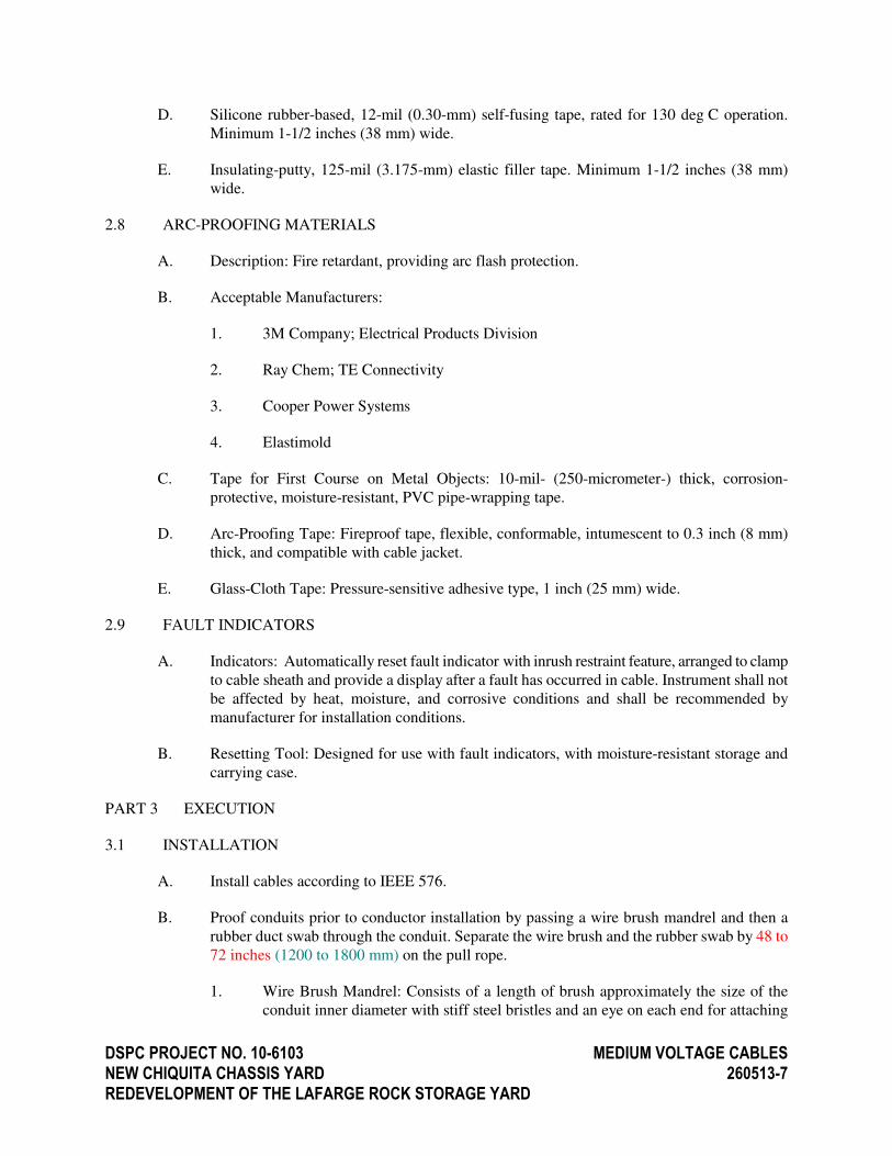
DSPC PROJECT NO. 10-6103 MEDIUM VOLTAGE CABLES
NEW CHIQUITA CHASSIS YARD 260513-7
REDEVELOPMENT OF THE LAFARGE ROCK STORAGE YARD
D. Silicone rubber-based, 12-mil (0.30-mm) self-fusing tape, rated for 130 deg C operation.
Minimum 1-1/2 inches (38 mm) wide.
E. Insulating-putty, 125-mil (3.175-mm) elastic filler tape. Minimum 1-1/2 inches (38 mm)
wide.
2.8 ARC-PROOFING MATERIALS
A. Description: Fire retardant, providing arc flash protection.
B. Acceptable Manufacturers:
1. 3M Company; Electrical Products Division
2. Ray Chem; TE Connectivity
3. Cooper Power Systems
4. Elastimold
C. Tape for First Course on Metal Objects: 10-mil- (250-micrometer-) thick, corrosion-
protective, moisture-resistant, PVC pipe-wrapping tape.
D. Arc-Proofing Tape: Fireproof tape, flexible, conformable, intumescent to 0.3 inch (8 mm)
thick, and compatible with cable jacket.
E. Glass-Cloth Tape: Pressure-sensitive adhesive type, 1 inch (25 mm) wide.
2.9 FAULT INDICATORS
A. Indicators: Automatically reset fault indicator with inrush restraint feature, arranged to clamp
to cable sheath and provide a display after a fault has occurred in cable. Instrument shall not
be affected by heat, moisture, and corrosive conditions and shall be recommended by
manufacturer for installation conditions.
B. Resetting Tool: Designed for use with fault indicators, with moisture-resistant storage and
carrying case.
PART 3 EXECUTION
3.1 INSTALLATION
A. Install cables according to IEEE 576.
B. Proof conduits prior to conductor installation by passing a wire brush mandrel and then a
rubber duct swab through the conduit. Separate the wire brush and the rubber swab by 48 to
72 inches (1200 to 1800 mm) on the pull rope.
1. Wire Brush Mandrel: Consists of a length of brush approximately the size of the
conduit inner diameter with stiff steel bristles and an eye on each end for attaching

DSPC PROJECT NO. 10-6103 MEDIUM VOLTAGE CABLES
NEW CHIQUITA CHASSIS YARD 260513-8
REDEVELOPMENT OF THE LAFARGE ROCK STORAGE YARD
the pull ropes. If an obstruction is felt, pull the brush back and forth repeatedly to
break up the obstruction.
2. Rubber Duct Swab: Consists of a series of rubber discs approximately the size of the
conduit inner diameter on a length of steel cable with an eye on each end for
attaching the pull ropes. Pull the rubber duct swab through the duct to extract loose
debris from the duct.
C. Pull Conductors: Do not exceed manufacturer's recommended maximum pulling tensions and
sidewall pressure values.
1. Where necessary, use manufacturer-approved pulling compound or lubricant that
does not deteriorate conductor or insulation.
2. Use pulling means, including fish tape, cable, rope, and basket-weave cable grips,
that do not damage cables and raceways. Do not use rope hitches for pulling
attachment to cable.
3. Use pull-in guides, cable feeders, and draw-in protectors as required to protect cables
during installation.
4. Do not pull cables with ends unsealed. Seal cable ends with rubber tape.
D. Install exposed cables parallel and perpendicular to surfaces of exposed structural members
and follow surface contours where possible.
E. Support cables according to Section 260529 "Hangers and Supports for Electrical Systems."
F. Install direct-buried cables on leveled and tamped bed of 3-inch- (75-mm-) thick, clean sand.
Separate cables crossing other cables or piping by a minimum of 2 inches (50 mm) of tamped
earth, plus an additional 2 inches (50 mm) of sand. Install permanent markers at ends of cable
runs, changes in direction, and buried splices.
G. Install "buried-cable" warning tape 12 inches (305 mm) above cables.
H. In manholes, handholes, pull boxes, junction boxes, and cable vaults, train cables around
walls by the longest route from entry to exit; support cables at intervals adequate to prevent
sag.
I. Install sufficient cable length to remove cable ends under pulling grips. Remove length of
conductor damaged during pulling.
J. Install cable splices at pull points and elsewhere as indicated; use standard kits. Use dead-
front separable watertight connectors in manholes and other locations subject to water
infiltration.
K. Install terminations at ends of conductors, and seal multiconductor cable ends with standard
kits.
L. Install separable insulated-connector components as follows:

DSPC PROJECT NO. 10-6103 MEDIUM VOLTAGE CABLES
NEW CHIQUITA CHASSIS YARD 260513-9
REDEVELOPMENT OF THE LAFARGE ROCK STORAGE YARD
1. Protective Cap: At each terminal junction, with one on each terminal to which no
feeder is indicated to be connected.
2. Portable Feed-Through Accessory: At each terminal junction, with one on each
terminal.
3. Standoff Insulator: At each terminal junction, with one on each terminal.
M. Arc Proofing: Unless otherwise indicated, arc proof medium-voltage cable at locations not
protected by conduit, cable tray, direct burial, or termination materials. In addition to arc-
proofing tape manufacturer's written instructions, apply arc proofing as follows:
1. Clean cable sheath.
2. Wrap metallic cable components with 10-mil (250-micrometer) pipe-wrapping tape.
3. Smooth surface contours with electrical insulation putty.
4. Apply arc-proofing tape in one half-lapped layer with coated side toward cable.
5. Band arc-proofing tape with two layers of 1-inch- (25-mm-) wide half-lapped,
adhesive, glass-cloth tape at each end of the arc-proof tape.
N. Seal around cables passing through fire-rated elements according to Section 260528
"Electrical Firestopping."
O. Install fault indicators on each phase where indicated.
P. Ground shields of shielded cable at terminations, splices, and separable insulated connectors.
Ground metal bodies of terminators, splices, cable and separable insulated-connector fittings,
and hardware.
Q. Ground shields of shielded cable at one point only. Maintain shield continuity and
connections to metal connection hardware at all connection points.
R. Identify cables according to Section 260553 "Identification for Electrical Systems." Identify
phase and circuit number of each conductor at each splice, termination, pull point, and
junction box. Arrange identification so that it is unnecessary to move the cable or conductor
to read the identification.
3.2 FIELD QUALITY CONTROL
A. Testing Agency: Engage a qualified testing agency to perform tests and inspections.
B. Manufacturer's Field Service: Engage a factory-authorized service representative to test and
inspect components, assemblies, and equipment installations, including connections.
C. Perform the following tests and inspections:
1. Perform each visual and mechanical inspection and electrical test stated in
NETA ATS. Certify compliance with test parameters.
DSPC PROJECT NO. 10-6103 MEDIUM VOLTAGE CABLES
NEW CHIQUITA CHASSIS YARD 260513-10
REDEVELOPMENT OF THE LAFARGE ROCK STORAGE YARD
2. After installing medium-voltage cables and before electrical circuitry has been
energized, test for compliance with requirements.
3. Perform direct-current High Potential test of each new conductor according to
NETA ATS, Ch. 7.3.3. Do not exceed cable manufacturer's recommended maximum
test voltage.
4. Perform Partial Discharge test of each new conductor according to NETA ATS,
Ch. 7.3.3 and to test equipment manufacturer's recommendations.
5. Perform Dissipation Factor test of each new conductor according to NETA ATS,
Ch. 7.3.3 and to test equipment manufacturer's recommendations.
D. Medium-voltage cables will be considered defective if they do not pass tests and inspections.
E. Prepare test and inspection reports.
END OF SECTION

DSPC PROJECT NO. 10-6103 MEDIUM VOLTAGE GROUNDING
NEW CHIQUITA CHASSIS YARD 260524-1
REDEVELOPMENT OF THE LAFARGE ROCK STORAGE YARD
DIVISION 26
SECTION 260524
MEDIUM VOLTAGE GROUNDING
TABLE OF CONTENTS
PART 1 GENERAL
1.1 RELATED DOCUMENTS
1.2 SUMMARY
1.3 REFERENCES
1.4 SYSTEM DESCRIPTION
1.5 PROJECT RECORD DOCUMENTS
1.6 REGULATORY REQUIREMENTS
1.7 QUALITY ASSURANCE
PART 2 PRODUCTS
2.1 CONDUCTORS
2.2 CONNECTORS
2.3 GROUNDING ELECTRODES
PART 3 EXECUTION
3.1 INSTALLATION
3.2 FIELD QUALITY CONTROL

DSPC PROJECT NO. 10-6103 MEDIUM VOLTAGE GROUNDING
NEW CHIQUITA CHASSIS YARD 260524-2
REDEVELOPMENT OF THE LAFARGE ROCK STORAGE YARD
SECTION 260524 - MEDIUM VOLTAGE GROUNDING
PART 1 GENERAL
1.1 RELATED DOCUMENTS
A. Drawings and general provisions of the Contract, including General and Supplementary
Conditions and Division 01 Specification Sections apply to this Section.
1.2 SUMMARY
A. Section includes medium voltage grounding including, but not limited to, the following:
1. Conductors
2. Connectors
3. Electrodes
B. Related requirements of the following Sections shall apply to this Section:
1. Division 26 Section, “Conductors and Cables”
2. Division 26 Section, “Underground Ductbanks”
1.3 REFERENCES
A. ANSI/IEEE 32 - Requirements, Terms and Test Procedures for Neutral Grounding Devices.
B. ANSI/IEEE C2 - National Electrical Safety Code.
C. ANSI/IEEE 81 - Guide for Measuring Earth Resistivity, Ground Impedance, and Earth
Surface Potentials of a Ground System.
1.4 SYSTEM DESCRIPTION
A. The medium voltage system utilized is 12470 (Grounded WYE)/7200 Volts (WYE)
connected.
1.5 PROJECT RECORD DOCUMENTS
A. Submit documents under provisions of Division 01 and Division 26 Section, “Common Work
Results for Electrical”, Article “Record Drawings”.
B. Accurately record exact locations of neutral and equipment grounding points and ground
electrodes.
1.6 REGULATORY REQUIREMENTS
A. Conform to ANSI/IEEE C2.
DSPC PROJECT NO. 10-6103 MEDIUM VOLTAGE GROUNDING
NEW CHIQUITA CHASSIS YARD 260524-3
REDEVELOPMENT OF THE LAFARGE ROCK STORAGE YARD
B. The underground distribution system shall be properly grounded, meeting all requirements of
the National Electrical Code, other applicable Federal, State and local electric codes, and the
requirements of these Specifications.
1.7 QUALITY ASSURANCE
A. Testing Agency Qualifications: An independent agency, with the experience and capability to
conduct the testing indicated, that is a member company of the International Electrical Testing
Association or is a nationally recognized testing laboratory (NRTL) as defined by OSHA in
29 CFR 1910.7, and that is acceptable to authorities having jurisdiction.
1. Testing Agency’s Field Supervisor: Person currently certified by the International
Electrical Testing Association to supervise on-site testing specified in Part 3 of this
Section.
B. Electrical Components, Devices, and Accessories: Listed and labeled as defined in NFPA 70.
Article 100, by a testing agency acceptable to authorities having jurisdiction, and marked for
intended use.
C. Comply with UL 467 “Standard for Grounding and Bonding Equipment” for grounding and
bonding materials and equipment.
PART 2 PRODUCTS
2.1 CONDUCTORS
A. Bare Copper Conductors
1. Stranded Conductors: ASTM B 8.
2.2 CONNECTORS
A. Listed and labeled by a nationally recognized testing laboratory acceptable to authorities
having jurisdiction for applications in which used, and for specific types, sizes, and
combinations of conductors and other items connected.
B. Bolted Connectors for Conductors: Copper or copper alloy, bolted pressure-type, with at least
two bolts.
C. Welded Connectors: Exothermic-welding kits of types recommended by kit manufacturer for
materials being joined and installation conditions.
2.3 GROUNDING ELECTRODES
A. Grounding Rods: Copper-clad rod with rigid steel core.
1. Size: 3/4 inch by 120 inches (19 by 3000 mm). Provide the number of rods required
to obtain proper ground resistance.

DSPC PROJECT NO. 10-6103 MEDIUM VOLTAGE GROUNDING
NEW CHIQUITA CHASSIS YARD 260524-4
REDEVELOPMENT OF THE LAFARGE ROCK STORAGE YARD
2. Rods shall have a minimum of ten (10) mils of copper.
3. Ground rods shall be UL listed #467.
PART 3 EXECUTION
3.1 INSTALLATION
A. Install grounding equipment in accordance with Specifications and Drawings
B. System shall include, but not be limited to, the following:
1. Ground rods for grounding the medium voltage distribution system shall be installed
at switchgear.
2. Grounding from medium voltage transformers to existing ground bar in transformer
vault.
3. Grounding from medium voltage lightning arresters to existing ground bar in
transformer vault.
3.2 FIELD QUALITY CONTROL
A. Test resistance to earth of grounding connections in accordance with ANSI/IEEE 81. Use
two-point method test to determine resistance between main system and neutral. Test cable in
accordance with NETA ATS (Acceptance Testing Specifications), Section 7.14, for electrical
power distribution equipment.
B. Maximum Acceptable Ground Resistance; 5 ohms.
C. A resistance of not greater than 5 ohms shall be required at all MV equipment pads,
manholes, etc. Ground resistance shall be measured in normally dry conditions, not less than
48 hours after a rainfall. Where a 5 ohm reading cannot be obtained, additional ground rods
may be driven and connected to others in order to obtain a resistance less than 5 ohms.
D. Investigate levels which exceed the above.
END OF SECTION
DSPC PROJECT NO. 10-6103 MEDIUM VOLTAGE TRANSFORMERS
NEW CHIQUITA CHASSIS YARD 261200-1
REDEVELOPMENT OF THE LAFARGE ROCK STORAGE YARD
DIVISION 26
SECTION 261200
MEDIUM VOLTAGE TRANSFORMERS
TABLE OF CONTENTS
PART 1 GENERAL
1.1 RELATED DOCUMENTS
1.2 SCOPE
1.3 APPLICABLE STANDARDS
1.4 SUBMITTALS
1.5 OPERATION AND MAINTENANCE DATA
1.6 QUALITY ASSURANCE
1.7 DELIVERY, STORAGE AND HANDLING
PART 2 PRODUCTS
2.1 MANUFACTURERS
2.2 OIL-FILLED TRANSFORMERS
PART 3 EXECUTION
3.1 EXAMINATION
3.2 INSTALLATION
3.3 EQUIPMENT MOUNTING PADS
3.4 FIELD QUALITY CONTROL
3.5 ADJUSTING

DSPC PROJECT NO. 10-6103 MEDIUM VOLTAGE TRANSFORMERS
NEW CHIQUITA CHASSIS YARD 261200-1
REDEVELOPMENT OF THE LAFARGE ROCK STORAGE YARD
SECTION 26 1200 - MEDIUM VOLTAGE TRANSFORMERS
PART 1 GENERAL
1.1 RELATED DOCUMENTS
A. Drawings and General Provisions of the Contract, including General and Supplementary
Conditions and Division 01, Specification Sections apply to this Section.
1.2 SCOPE
A. Applicable provisions of Division 01 shall apply to all work under this Section.
B. Provide new transformer as noted herein and on the Contract Drawings in accordance with the
Contract Documents.
1.3 APPLICABLE STANDARDS
A. IEEE C57.12.00™- Standard General Requirements for Liquid- Immersed Distribution,
Power, and Regulating Transformers.
B. IEEE C57.12.34™-- Requirements for Pad-Mounted, Compartmental-Type, Self Cooled,
Three-Phase Distribution Transformers 2,500 kVA and Smaller: High Voltage, 34,500
GrdY/19,920 Volts and Below; Low Voltage, 480 Volts and Below.
C. ANSI C57.12.28—Standard for Pad-Mounted Equipment-Enclosure Integrity.
D. IEEE C57.12.70™-- Standard for Terminal Markings and Connections for Distribution
and Power Transformers.
E. IEEE C57.12.80™-- Standard Terminology for Power and Distribution Transformers.
FPO
F. IEEE C57.12.90™-- Standard Test Code for Liquid-Immersed Distribution Power, and
Regulating Transformers and Guide for Short-Circuit Testing of Distribution and Power
Transformers.
G. IEEE C57.13™-- Requirements for Instrument Transformers.
H. ANSI/IEEE 386- Separable Insulated Connector Systems for Power Distribution Systems
Above 600V.
I. ASTM D877—Test Method for Dielectric Breakdown Voltage of Insulating Liquids
Using Disk Electrodes.
J. NEMA AB1- Molded Case Circuit Breakers.
K. NEMA TR1- Transformers, Regulators and Reactors
L. CAN/CSA-C88-M90---- Electrical Power Systems and Equipment.

DSPC PROJECT NO. 10-6103 MEDIUM VOLTAGE TRANSFORMERS
NEW CHIQUITA CHASSIS YARD 261200-2
REDEVELOPMENT OF THE LAFARGE ROCK STORAGE YARD
1.4 SUBMITTALS
A. Shop Drawings
1. Submit product data under provisions of General Conditions of the Contract and
Division 26 Section, Common Work Results for Electrical.
2. Include outline and support point dimensions of enclosures and accessories, unit
weight, voltage, kVa, and impedance ratings and characteristics, loss data, efficiency
at 25, 50, 75 and 100 percent rated load, sound level, tap configurations, insulation
system type, and rated temperature rise.
3. Include detailed drawings of any changes to existing installations to suit proposed
equipment to be furnished.
4. Include manufacturer's installation instructions.
5. Submit a ¼-inch scaled shop drawing indicating transformer(s), equipment pad,
clearances, dimensions, existing conditions, and other major components. Shop
drawing shall be specific to location being installed.
B. Factory Certified Tests
1. Factory certified tests shall be performed on the transformer being supplied and the
results presented to the Project Manager for approval before shipment. The
following factory certified tests shall be performed:
a. Insulation resistance tests shall be performed winding-to-winding and
winding-to ground.
b. A turns ratio test shall be performed between windings at all service tap
settings.
c. Overpotential test shall be made on all high and low voltage windings to
ground.
d. Winding resistance tests shall be made for each winding at the in-service tap.
e. Verify that the tap settings/changer is at the desired ratio.
f. Measure secondary voltage phase-to-phase and phase-to-ground after final
energization and prior to loading.
g. Verify and/or connect transformer "XO" to ground, load side of "WYE"
systems.
1.5 OPERATION AND MAINTENANCE DATA

DSPC PROJECT NO. 10-6103 MEDIUM VOLTAGE TRANSFORMERS
NEW CHIQUITA CHASSIS YARD 261200-3
REDEVELOPMENT OF THE LAFARGE ROCK STORAGE YARD
A. Submit operation and maintenance data under provisions of General Conditions of the
Contract and Division 26 Section, Common Work Results for Electrical.
B. Include procedures for cleaning unit, maintaining fluid levels, and replacing components.
1.6 QUALITY ASSURANCE
A. Manufacturer: Company specializing in distribution transformers with ten years experience.
B. Comply with the latest requirements of IEEE, ANSI, ASTM, NEMA, and ASA-NEMA
Standards.
1.7 DELIVERY, STORAGE, AND HANDLING
A. Store and protect equipment in a warm, dry location with uniform temperature. Cover
ventilating openings to keep out dust.
B. Protect dry type transformers from moisture by using appropriate heaters as instructed by the
manufacturer.
C. Handle transformers using only lifting eyes and brackets provided for that purpose. Protect
units against entrance of rain, sleet, or snow if handled in inclement weather.
PART 2 PRODUCTS
2.1 MANUFACTURERS
A. Available Manufacturers: Subject to compliance with requirements, manufacturers
offering products that may be incorporated into the Work include, but are not limited to
the following:
1. ABB
2. Eaton / Cooper Power Systems
3. Square D Company
2.2 OIL-FILLED TRANSFORMERS
A. Furnish and install at the locations indicated on Drawings, completely metal enclosed,
compartmented, oil-filled, pad-mounted distribution transformers.
B. Equipment shall have the following ratings:
1. Capacity - 2500 KVA @ 65 degrees C Rise.
2. Primary Voltage - 12,470V, 3-phase, 3-wire (Delta).
3. Secondary Voltage: - 208Y/120V, 3-phase, 4-wire (Wye).
4. Taps: - Two (2) @ 2-1/2 percent Above and Below
Nominal.

DSPC PROJECT NO. 10-6103 MEDIUM VOLTAGE TRANSFORMERS
NEW CHIQUITA CHASSIS YARD 261200-4
REDEVELOPMENT OF THE LAFARGE ROCK STORAGE YARD
5. Phase: - Three.
6. Frequency: - 60 Hertz.
7. B.I.L. - 125 kV.
8. Insulation - O.I.S.C.
9. Impedance - 5.75 percent Nominal
10. Dead Front Construction
C. The unit shall be constructed for outdoor, fenceless, weatherproof service, and shall be
suitable for mounting directly on the concrete foundation pad with high and low voltage cable
entrance from below. The front of the unit shall contain an air-filled termination chamber
divided with a steel barrier into two sections. The left section shall contain three porcelain
live front eyebolt horizontal bushings situated to provide at least 30-inches of vertical space
for cable training and termination. Include three 10 kV distribution class metal oxide surge
arrestors mounted in this compartment connected to the above bushings. The low voltage
compartment shall contain four 10-hole NEMA drilled spade type side wall bushings.
Provide low voltage barrier.
D. The transformer shall be of sealed tank construction and furnished with the following:
1. Combination drain and sampler valve (minimum 1-inch).
2. Upper filter press connection.
3. Liquid level gauge.
4. Dial thermometer.
5. Manual tap changer handle.
6. Pressure relief valve.
7. Lifting lugs.
8. Grounding pads.
9. Jacking lugs.
10. Tamper-proof handhole on tank.
11. Diagrammatic nameplate.
12. Provisions for padlocking and recessed bolting the hinged doors of the air terminal
chamber with access to the high voltage section only after opening the low voltage
section door.

DSPC PROJECT NO. 10-6103 MEDIUM VOLTAGE TRANSFORMERS
NEW CHIQUITA CHASSIS YARD 261200-5
REDEVELOPMENT OF THE LAFARGE ROCK STORAGE YARD
13. Non-PCB Certification label.
14. ANSI Tank Ground Pad.
15. Filling plug-mounted in the cover.
16. Tap changer handle.
17. Vacuum/Pressure Gauge.
18. Liquid Temperature Gauge.
19. Winding Temperature Gauge with alarm contacts and control relays.
20. WARNING - HIGH VOLTAGE Label.
E. The unit shall be constructed of welded steel plate with no exposed bolt-heads, protrusions,
sharp edges, or openings which would permit entrance by other than authorized personnel.
The entire assembly shall be cleaned of weld scale, primed, and given a finish coat of "Forest
Green", oil-resistance outdoor enamel paint, or other color as selected by the Owner.
F. The transformer shall be manufactured and tested in accordance with the latest applicable
requirements of IEEE, NEMA and ANSI and shall be as manufactured by acceptable
manufacturers as specified herein.
G. Liquid: Oil or less flammable liquid may be used depending on where installed and how the
vault is constructed. All oil shall be non-PCB. A permanent label shall be affixed to the
tank indicating transformer dielectric fluids contained less than 50 PPM of PCB in accordance
with EPA Requirements at the time of shipment.
H. Primary Terminations:
1. All transformers shall have dead front terminations.
2. Provide three (3) ANSI/IEEE 386 bushing wells, insulated load-break connectors
with parking stands, and one (1) internal oil-immersed, two-position load-break
switch.
I. Primary Overcurrent Protection: Two fuse system consisting of Bayonet-type, oil-immersed
expulsion fuse in series with current-limiting backup fuse mounted inside the transformer
under oil. The current limiting fuse should be located as near as practical to the incoming
primary bushing, on the source side of the expulsion fuse. The two fuses shall be coordinated
so that the expulsion fuse clears low energy faults on the secondary system and the current
limiting fuse clears only high energy, includes overload protection, can be provided as an
alternate with approval from the Owner. All transformer fusing shall be coordinated with
upstream phase overcurrent devices.
J. Copper windings.
DSPC PROJECT NO. 10-6103 MEDIUM VOLTAGE TRANSFORMERS
NEW CHIQUITA CHASSIS YARD 261200-6
REDEVELOPMENT OF THE LAFARGE ROCK STORAGE YARD
K. Transformer Start-Up: The transformer will not be started until all tests are complete and
turned over to the Owner and the Engineer for review and approval.
PART 3 EXECUTION
3.1 EXAMINATION
A. Verify field measurements are as shown on Drawings.
B. Verify that required utilities are available, in proper location and ready for use.
C. Beginning of installation means installer accepts conditions.
3.2 INSTALLATION
A. Install in accordance with manufacturer's instructions.
B. Set transformer plumb and level.
C. Connect transformer to adjacent equipment using new cables.
D. Mount primary surge arresters inside of transformers.
E. Provide safety labels per NEMA 260.
3.3 EQUIPMENT MOUNTING PADS
A. Construct equipment mounting pads per manufacturer’s and Construction Documents
requirements.
3.4 FIELD QUALITY CONTROL
A. Oil Filled Transformers: Field testing will be performed by independent testing agency
provided by the Contractor. Perform testing as required by NETA and as follows:
1. Sample insulating liquid in accordance with ASTM D3613 and perform dissolved
gas analysis (DGA) in accordance with ANSI / IEEE and ASTM.
2. Turns ratio tests on the rated voltage connection and on all tap connections.
3. Polarity and phase-relation tests on the rated voltage connection.
4. Power factor tests in accordance with manufacturer's instructions.
5. Dielectric absorption test, winding-winding, and winding-ground.
6. Core insulation resistance, winding-winding, and winding-ground tests.
7. Winding resistance for each winding at nominal tap position.

DSPC PROJECT NO. 10-6103 MEDIUM VOLTAGE TRANSFORMERS
NEW CHIQUITA CHASSIS YARD 261200-7
REDEVELOPMENT OF THE LAFARGE ROCK STORAGE YARD
8. AC Overpotential Test on all high and low voltage windings to ground.
B. Factory test transformer to ANSI/IEEE C57.12.91 and provide the Owner with the test results
prior to setting the transformer.
C. Field test the transformer to ANSI / IEEE C57.12.91. All field tests to be witnessed by the
Owner. All test reports shall be turned over to the Owner.
D. Any equipment which fails any of the required tests shall be replaced with new, or repaired at
Owner's discretion. Equipment with marginal results, as interpreted by the Owner or
Engineer, shall also be replaced or repaired at the Owner's discretion.
E. Check for damage and tight connections prior to energizing transformer.
3.5 ADJUSTING
A. Adjust primary taps so that secondary voltage is within 1.5 percent of rated voltage.
END OF SECTION

DSPC PROJECT NO. 10-6103 MEDIUM VOLTAGE SWITCHGEAR
NEW CHIQUITA CHASSIS YARD 261301-1
REDEVELOPMENT OF THE LAFARGE ROCK STORAGE YARD
DIVISION 26
SECTION 261301
MEDIUM VOLTAGE PAD MOUNTED SWITCHGEAR
TABLE OF CONTENTS
PART 1 GENERAL
1.1 RELATED DOCUMENTS
1.2 REFERENCE
1.3 CODES AND STANDARDS
1.4 SUBMITTALS
1.5 OPERATION AND MAINTENANCE DATA
1.6 QUALITY ASSURANCE
1.7 DELIVERY, STORAGE AND HANDLING
1.8 EXTRA MATERIALS
1.9 COMPLIANCE WITH STANDARDS AND CODES
PART 2 PRODUCTS
2.1 MANUFACTURERS
2.2 ENCLOSURE DESIGN
2.3 RATINGS
2.4 INSULATION
2.5 HIGH VOLTAGE BUS
2.6 GROUND-CONNECTION PADS
2.7 ENCLOSURE
2.8 DOORS
2.9 FINISH
2.10 CORROSION RESISTANCE
2.11 INTERRUPTER SWITCHES
2.12 FUSES
2.13 LABELING
2.14 ACCESSORIES
PART 3 EXECUTION
3.1 MISCELLANEOUS INSTALLATION REQUIREMENTS
3.2 INSPECTION AND TEST REQUIREMENTS
DSPC PROJECT NO. 10-6103 MEDIUM VOLTAGE SWITCHGEAR
NEW CHIQUITA CHASSIS YARD 261301-2
REDEVELOPMENT OF THE LAFARGE ROCK STORAGE YARD
SECTION 261301 - MEDIUM VOLTAGE PAD MOUNTED SWITCHGEAR
PART 1 GENERAL
1.1 RELATED DOCUMENTS
A. Drawings and general provisions of the Contract, including General and Supplementary
Conditions and Division 01, Specification Sections apply to this Section.
1.2 REFERENCE
A. All work under this Section shall be subject to Division 26 Section, “Common Work
Results for Electrical” and any applicable conditions hereinbefore written for the entire
work.
B. This section describes metal-enclosed switchgear assembly for application as Customer-
Owned 15 kV equipment for installation after the utility company’s metering compartment
and ahead of the customer-owned medium voltage transformers.
1.3 CODES AND STANDARDS:
A. The equipment furnished under this Section shall be in accordance with the latest
applicable standards of ANSI, NEMA, IEEE, ICEA, OSHA, National Electrical Code and
National Electric Safety Code.
B. Where any requirements specified herein or shown on the Contract Drawings exceed the
listed standards, adhere to the higher standard. In case of conflict in requirements between
two of more standards, decision of the Engineer shall be final.
C. All equipment and materials furnished under this Section shall conform to all Federal,
State, and Local laws or ordinances, and if any requirements shown or specified conflicts
with such requirements, laws or ordinances, provide such changes as are necessary to
meet said requirements. The cost of such changes shall be included in the original bid.
Where any standards shown on the Contract Drawings or specified herein exceed the
minimum standards set by law, adhere to the higher standard.
D. Where applicable, all equipment and materials shall be listed and labeled by a nationally-
recognized testing laboratory with equipment listing and follow-up service.
E. Switchgear shall be UL listed.
F. References
1. ANSI/IEEE C37.20.3 - Standard for Metal-Enclosed Interrupter Switchgear.
2. ANSI/IEEE C37.30 - Standard Definitions and Requirements for High-Voltage
Air Switches, Insulators, and Bus Supports.
DSPC PROJECT NO. 10-6103 MEDIUM VOLTAGE SWITCHGEAR
NEW CHIQUITA CHASSIS YARD 261301-3
REDEVELOPMENT OF THE LAFARGE ROCK STORAGE YARD
3. ANSI/IEEE C37.32 - Standard Schedules of Preferred Ratings, Manufacturing
Specifications, and Application Guide for High-Voltage Air Switches, Bus
Supports, and Switch Accessories.
4. ANSI/IEEE C37.34 - Test Code for High Voltage Air Switches.
5. ANSI/IEEE C37.35 - Guide for the Application, Installation, Operation, and
Maintenance of High-Voltage Air Disconnecting and Load Interrupter Switches.
6. ANSI Standard - Green Finishes for Apparatus and Equipment.
7. Local Electrical Codes.
8. NFPA 70 - National Electrical Code, latest edition.
1.4 SUBMITTALS
A. Provide third party certified test abstracts for all air interrupter switchgear proposed for
use on this project prior to shop drawing submittal and not later than twenty-one days
after award of contract. The certified test abstracts shall contain, as a minimum, the
manufacturers current engineering sales brochure showing all equipment proposed with
model numbers (if available), and a summary of test procedures (described below) and
resultant values actually recorded during the tests. The test procedure and resultant values
summary shall contain model numbers (if available) similar to those listed in the current
engineering sales brochure.
B. The following tests shall be performed on assemblies similar to those proposed for this
project. Assemblies shall be complete with enclosure and all internal components such as
switch, fuses (if required), ground pads, ground rods, metal and insulating barriers, etc.
1. Short-time current testing, to include rated momentary and rated three second tests
as defined in ANSI/IEEE C237.30.4.6 and C37.20.3.5.2.
2. Rated continuous current and temperature rise testing as defined in ANSI/IEEE
C37.32.3.2, C37.20.3.5.2, and C37.30.4.5.
3. Dielectric testing to include impulse withstand and 60 Hz tests as defined in
ANSI/IEEE C37.32.3.2.
4. Load current interrupting testing as defined in ANSI/IEEE C37.30.4.7.
5. Fault closing tests within the enclosure: 3 phase testing on the switch and 1
phase testing on the fuses as defined in ANSI/IEEE C37.30.4.14.
6. Finish testing as defined in ANSI/IEEE C37.20.3.5.2.8. Samples must be
prepared by the equipment manufacturer, not by the coating vendor, using
production painting equipment with production paint applied on production
substrates identical to that used of this project's equipment.

DSPC PROJECT NO. 10-6103 MEDIUM VOLTAGE SWITCHGEAR
NEW CHIQUITA CHASSIS YARD 261301-4
REDEVELOPMENT OF THE LAFARGE ROCK STORAGE YARD
C. Submit the following shop drawings under the provisions of Division 01of the Contract
and of this Division.
1. Outline dimensions, enclosure construction, shipping splits, lifting and supporting
points.
2. Conduit and cable entrance locations.
3. Electrical single line diagram.
4. Equipment electrical ratings.
5. Certification of ratings of the integrated metal-enclosed switchgear assembly
consist of the basic switch and fuse components in combination with the
enclosure.
6. Product data for components and accessories.
7. Manufacturer's installation instructions.
8. Fuse curves for proposed fuses.
1.5 OPERATION AND MAINTENANCE DATA
A. Submit operation and maintenance data under provisions of General Conditions.
B. Include parts list, fuse replacement, equipment adjustment, and lubrication instructions.
1.6 QUALITY ASSURANCE
A. Enclosure Manufacturer: Company specializing in medium voltage interrupter switch
enclosures with thirty years documented experience.
B. Switch Manufacturer: Company specializing in medium voltage interrupter switch
components with five years documented experience.
C. Fuse Manufacturer; Company specializing in medium voltage fuses and fuse components
with five years documented experience.
D. The manufacturer/assembler of the overall switchgear assembly shall be completely and
solely responsible for the performance of the basic switch as well as the complete
integrated assembly as rated.
1.7 DELIVERY, STORAGE, AND HANDLING
A. Deliver products to site and protect from damage.
B. Store and protect products.
C. Accept switchgear on site and inspect of damage.

DSPC PROJECT NO. 10-6103 MEDIUM VOLTAGE SWITCHGEAR
NEW CHIQUITA CHASSIS YARD 261301-5
REDEVELOPMENT OF THE LAFARGE ROCK STORAGE YARD
1.8 EXTRA MATERIALS
A. Provide maintenance materials under provisions of Section "General Electrical
Requirements" and Division 01, Section "Closeout Procedures".
B. Provide one (1) 15 kV hot stick designed for pulling fuses.
C. Provide one set of spare fuses for each set installed. Place these spare fuses in the metal
pocket in the front door of each fused switch assembly.
1.9 COMPLIANCE WITH STANDARDS AND CODES:
A. The pad-mounted gear shall conform to or exceed the applicable requirements of the
following standards and codes:
1. All portions of ANSI C57.12.28, covering enclosure integrity for pad-mounted
equipment.
2. Article 490.21(e) in the National Electrical Code, which specifies that the
interrupter switches in combination with power fuses shall safely withstand the
effects of closing, carrying, and interrupting all possible currents up to the
assigned maximum short-circuit rating.
3. All portions of ANSI, IEEE, and NEMA standards applicable to the basic switch
and fuse components.
PART 2 PRODUCTS
2.1 MANUFACTURERS
A. Manufacturers: Subject to compliance with requirements, manufacturers offering products
that may be incorporated into the Work include, the following:
1. S & C Electrical (Basis of Design).
2. Square D; Schneider Electric.
3. ABB Control, Inc.
2.2 ENCLOSURE DESIGN:
A. To ensure a completely coordinated design, the pad-mounted gear shall be constructed in
accordance with the minimum construction specifications of the fuse and/or switch
manufacturer to provide adequate electrical clearances and adequate space for fuse
handling.
B. In establishing the requirements for the enclosure design, consideration shall be given to
all relevant factors such as controlled access, tamper resistance, and corrosion resistance.
2.3 RATINGS

DSPC PROJECT NO. 10-6103 MEDIUM VOLTAGE SWITCHGEAR
NEW CHIQUITA CHASSIS YARD 261301-6
REDEVELOPMENT OF THE LAFARGE ROCK STORAGE YARD
A. Ratings: The ratings for the integrated pad-mounted gear shall be as scheduled on the
Contract Drawings.
B. The momentary and two-time duty-cycle fault-closing ratings of switches, momentary
rating of bus, interrupting ratings of fuses, and one-time duty-cycle fault-closing
capabilities of fuses with integral load interrupters shall equal or exceed the short-circuit
ratings of the pad-mounted gear.
C. The manufacturer of the pad-mounted gear shall be completely and solely responsible for
the performance of the basic switch and fuse components as well as the complete
integrated assembly as rated.
D. The manufacturer shall furnish, upon request, certification of ratings of the basic switch
and fuse components and/or the integrated pad-mounted gear assembly consisting of the
switch and fuse components in combination with the enclosure.
2.4 INSULATION
A. The interrupter-switch and fuse-mounting insulators shall be of a cycloaliphatic epoxy
resin system with characteristics and restrictions as follows:
B. Operating experience of at least 15 years under similar conditions.
C. Adequate leakage distance established by test per IEC Publication 507, First Edition,
1975.
D. Adequate strength for short-circuit stress established by test.
E. Conformance with applicable ANSI standards.
F. Homogeneity of the cycloaliphatic epoxy resin throughout each insulator to provide
maximum resistance to power arcs. Ablation due to high temperatures from power arcs
shall continuously expose more material of the same composition and properties so that no
change in mechanical or electrical characteristics takes place because of arc-induced
ablation. Furthermore, any surface damage to insulators during installation or main-
tenance of the pad-mounted gear shall expose material of the same composition and
properties so that insulators with minor surface damage need not be replaced.
2.5 HIGH VOLTAGE BUS
A. Bus and interconnections shall consist of aluminum bar of 56% IACS conductivity.
B. Bus and interconnections shall withstand the stresses associated with short-circuit currents
up through the maximum rating of the pad-mounted gear.
C. Bolted aluminum-to-aluminum connections shall be made with a suitable number of
1/2"—13 galvanized steel bolts and with two Belleville spring washers per bolt, one under
the bolt head and one under the nut. Bolts shall be tightened to manufacturers
specifications.

DSPC PROJECT NO. 10-6103 MEDIUM VOLTAGE SWITCHGEAR
NEW CHIQUITA CHASSIS YARD 261301-7
REDEVELOPMENT OF THE LAFARGE ROCK STORAGE YARD
D. Before installation of the bus, all electrical contact surfaces shall first be prepared by
machine abrading to remove any aluminum-oxide film. Immediately after this operation,
the electrical contact surfaces shall be coated with a uniform coating of an oxide inhibitor
and sealant.
2.6 GROUND-CONNECTION PADS
A. A ground-connection pad shall be provided in each compartment of the pad-mounted gear.
B. The ground-connection pad shall be constructed of 3/16” thick steel, which shall be nickel
plated and welded to the enclosure, and shall have a short-circuit rating equal to that of the
pad-mounted gear.
C. Ground-connection pads shall be coated with a uniform coating of an oxide inhibitor and
sealant prior to shipment.
2.7 ENCLOSURE
A. The pad-mounted gear enclosure shall be of unitized monocoque (not structural-frame-
and-bolted-sheet) construction to maximize strength, minimize weight, and inhibit
corrosion.
B. The basic material shall be 11-gauge hot-rolled, pickled and oiled steel sheet.
C. All structural joints and butt joints shall be welded, and the external seams shall be ground
flush and smooth. The gas-metal-arc welding process shall be employed to eliminate
alkaline residues and to minimize distortion and spatter.
D. To guard against unauthorized or inadvertent entry, enclosure construction shall not utilize
any externally accessible hardware.
E. The base shall consist of continuous 90-degree flanges, turned inward and welded at the
corners, for bolting to the concrete pad.
F. The door openings shall have 90-degree flanges, facing outward, that shall provide
strength and rigidity as well as deep overlapping between doors and door openings to
guard against water entry.
G. Polyurethane self-adhesive bumpers shall be placed on the left-hand door channel to
prevent the right-hand door from abrading the paint, and on the center door divider to
prevent the left-hand door from rubbing against the center door divider.
H. Enclosure top side edges shall overlap with roof side edges to create a mechanical maze
which shall allow ventilation to help keep the enclosure interior dry while discouraging
tampering or insertion of foreign objects.
I. A heavy coat of insulating "no-drip" compound shall be applied to the inside surface of
the roof to minimize condensation of moisture thereon.

DSPC PROJECT NO. 10-6103 MEDIUM VOLTAGE SWITCHGEAR
NEW CHIQUITA CHASSIS YARD 261301-8
REDEVELOPMENT OF THE LAFARGE ROCK STORAGE YARD
J. Insulating interphase and end barriers of NEMA GPO3-grade fiberglass-reinforced
polyester shall be provided for each interrupter switch and each set of fuses where
required to achieve BIL ratings. Additional insulating barriers of the same material shall
separate the front compartments from the rear compartments and isolate the tie bus (where
furnished).
K. Full-length steel barriers shall separate side-by-side compartments.
L. Interrupter switches shall be provided with dual-purpose front barriers. These barriers, in
their normal hanging positions, shall guard against inadvertent contact with live parts. It
shall also be possible to lift the barriers out and insert them into the open gap when the
switch is open. These barriers shall meet the requirements of Section 381G of the
National Electrical Safety Code (ANSI Standard C2).
M. Interrupter switches shall be provided with window panels to allow viewing of the switch
position without removing the dual-purpose front barriers. Window panels shall be
removable to facilitate phasing and shall be secured to the enclosure with stainless-steel or
zinc-nickel-plated hardware.
N. Each fuse shall be provided with a dual-purpose front barrier. These barriers, in their
normal hanging positions, shall guard against inadvertent contact with live parts. It shall
also be possible to lift these barriers out and insert them into the open gaps when the fuses
are in the disconnect position. These barriers shall meet the requirements of Section 381G
of the National Electrical Safety Code (ANSI Standard C2).
O. The enclosure shall be provided with an instruction manual holder.
P. Lifting tabs shall be removable. Sockets for the lifting-tab bolts shall be blind-tapped. A
resilient material shall be placed between the lifting tabs and the enclosure to help prevent
corrosion by protecting the finish against scratching by the tabs. To further preclude
corrosion, this material shall be closed-cell to prevent moisture from being absorbed and
held between the tabs and the enclosure in the event that lifting tabs are not removed.
Q. A non-compartmented base spacer shall be provided to increase the elevation of live parts
in the pad-mounted gear above the mounting by 12-inches.
2.8 DOORS
A. Doors shall be constructed of 11 gauge hot-rolled, pickled and oiled steel sheets.
B. Door-edge flanges shall overlap with door-opening flanges and shall be formed to create a
mechanical maze that shall guard against water entry and discourage tampering or
insertion of foreign objects, but shall allow ventilation to help keep the enclosure interior
dry.
C. Doors shall have a minimum of two extruded-aluminum hinges with stainless-steel hinge
pins, and interlocking extruded-aluminum hinge supports for the full length of the door to
provide strength, security, and corrosion resistance. Mounting hardware shall be stainless
steel or zinc-nickel-plated steel, and shall not be externally accessible to guard against
tampering.

DSPC PROJECT NO. 10-6103 MEDIUM VOLTAGE SWITCHGEAR
NEW CHIQUITA CHASSIS YARD 261301-9
REDEVELOPMENT OF THE LAFARGE ROCK STORAGE YARD
D. In consideration of controlled access and tamper resistance, each door (or set of double
doors) shall be equipped with an automatic three-point latching mechanism.
1. The latching mechanism shall be spring loaded, and shall latch automatically
when the door is closed. All latch points shall latch at the same time to preclude
partial latching.
2. A pentahead socket wrench or tool shall be required to actuate the mechanism to
unlatch the door and, in the same motion, recharge the spring for the next closing
operation.
3. The latching mechanism shall have provisions for padlocking that incorporate a
means to protect the padlock shackle from tampering and that shall be coordinated
with the latches such that:
a. It shall not be possible to unlatch the mechanism until the padlock is
removed, and
b. It shall not be possible to insert the padlock until the mechanism is
completely latched closed.
4. Doors providing access to solid-material power fuses shall have provisions to
store spare fuse units or refill units.
5. Each door shall be provided with a zinc-nickel-plated steel door holder located
above the door opening. The holder shall be hidden from view when the door is
closed, and it shall not be possible for the holder to swing inside the enclosure.
2.9 FINISH
A. Full coverage at joints and blind areas shall be achieved by processing enclosures
independently of components such as doors and roofs before assembly into the unitized
structures.
B. All exterior seams shall be filled and sanded smooth for neat appearance.
C. To remove oils and dirt, to form a chemically and anodically neutral conversion coating to
improve the finish-to-metal bond, and to retard underfilm propagation of corrosion, all
surfaces shall undergo a thorough pretreatment process comprised of a fully automated
system of cleaning, rinsing, phosphatizing, sealing, drying, and cooling before any
protective coatings are applied. By utilizing an automated pretreatment process, the
enclosure shall receive a highly consistent thorough treatment, eliminating fluctuations in
reaction time, reaction temperature, and chemical concentrations.
D. After pretreatment, protective coatings shall be applied that shall help resist corrosion and
protect the steel enclosure. To establish the capability to resist corrosion and protect the
enclosure, representative test specimens coated by the enclosure manufacturer's finishing
system shall satisfactorily pass the following tests:
1. 4000 hours of exposure to salt-spray testing per ASTM B 117 with:
DSPC PROJECT NO. 10-6103 MEDIUM VOLTAGE SWITCHGEAR
NEW CHIQUITA CHASSIS YARD 261301-10
REDEVELOPMENT OF THE LAFARGE ROCK STORAGE YARD
a. Underfilm corrosion not to extend more than 1/32" from the scribe as
evaluated per ASTM D 1645, Procedure A, Method 2 (scraping); and
b. Loss of adhesion from bare metal not to extend more than 1/8" from the
scribe.
2. 1000 hours of humidity testing per ASTM D 4585 using the Cleveland
Condensing Type Humidity Cabinet with no blistering as evaluated per ASTM D
714.
3. 500 hours of accelerated weathering testing per ASTM G 53 using lamp
UVB-313 with no chalking as evaluated per ASTM D 659, and no more than 10%
reduction of gloss as evaluated per ASTM D 523.
4. Crosshatch adhesion testing per ASTM D 3359 Method B with no loss of finish.
5. 160-inch-pound impact adhesion testing per ASTM D 2794 with no chipping or
cracking.
6. Oil resistance testing consisting of a 72-hour immersion bath in mineral oil with
no shift in color, no streaking, no blistering, and no loss of hardness.
7. 3000 cycles of abrasion testing per ASTM 4060 with no penetration to the
substrate.
8. Certified test abstracts substantiating the above capabilities shall be furnished
upon request.
E. After the finishing system has been properly applied and cured, welds along the enclosure
bottom flange shall be coated with a wax-based anticorrosion moisture barrier to give
these areas added corrosion resistance.
F. A resilient closed-cell material, such as PVC gasket, shall be applied to the entire
underside of the enclosure bottom flange to protect the finish on this surface from
scratching during handling and installation. This material shall isolate the bottom flange
from the alkalinity of a concrete foundation to help protect against corrosive attack.
G. After the enclosure is completely assembled and the components (switches, fuses, bus,
etc.) are installed, the finish shall be inspected for scuffs and scratches. Blemishes shall
be touched up by hand to restore the protective integrity of the finish.
H. The finish shall be selected by the Owner from manufacturer’s standard finish options.
2.10 CORROSION RESISTANCE
A. To guard against corrosion, all hardware (including door fittings, fasteners, etc.), all
operating-mechanism parts, and other parts subject to abrasive action from mechanical
motion shall be of either nonferrous materials, or galvanized or zinc-nickel-plated ferrous
materials. Cadmium-plated ferrous parts shall not be used.
2.11 INTERRUPTER SWITCHES

DSPC PROJECT NO. 10-6103 MEDIUM VOLTAGE SWITCHGEAR
NEW CHIQUITA CHASSIS YARD 261301-11
REDEVELOPMENT OF THE LAFARGE ROCK STORAGE YARD
A. Interrupter switches shall have a two-time duty-cycle fault-closing rating equal to or
exceeding the short-circuit rating of the pad-mounted gear. These ratings define the
ability to close the interrupter switch twice against a three-phase fault with asymmetrical
current in at least one phase equal to the rated value, with the switch remaining operable
and able to carry and interrupt rated current. Tests substantiating these ratings shall be
performed at maximum voltage with current applied for at least 10 cycles. Certified test
abstracts establishing such ratings shall be furnished upon request.
B. Interrupter switches shall be operated by means of an externally accessible 3/4" hex
switch-operating hub. The switch-operating hub shall be located within a recessed
stainless-steel pocket mounted on the side of the pad-mounted gear enclosure and shall
accommodate a 3/4" deep-socket wrench or a 3/4" shallow-socket wrench with extension.
The switch-operating-hub pocket shall include a padlockable stainless-steel access cover
that shall incorporate a hood to protect the padlock shackle from tampering. Stops shall be
provided on the switch-operating hub to prevent overtravel and thereby guard against
damage to the interrupter switch quick-make quick-break mechanism. Labels to indicate
switch position shall be provided in the switch-operating-hub pocket.
C. Each interrupter switch shall be provided with a folding switch-operating handle. The
switch-operating handle shall be secured to the inside of the switch-operating-hub pocket
by a brass chain. The folded handle shall be stored behind the closed switch-operating-
hub access cover.
D. Interrupter switches shall utilize a quick-make quick-break mechanism installed by the
switch manufacturer. The quick-make quick-break mechanism shall be integrally
mounted on the switch frame, and shall swiftly and positively open and close the
interrupter switch independent of the switch-operating-hub speed.
E. Each interrupter switch shall be completely assembled and adjusted by the switch
manufacturer on a single rigid mounting frame. The frame shall be of welded steel
construction such that the frame intercepts the leakage path which parallels the open gap
of the interrupter switch to positively isolate the load circuit when the interrupter switch is
in the open position.
F. Interrupter switch contacts shall be backed up by stainless-steel springs to provide
constant high contact pressure.
G. Interrupter switches shall be provided with a single blade per phase for circuit closing
including fault closing, continuous current carrying, and circuit interrupting. Spring-
loaded auxiliary blades shall not be permitted. Interrupter switch blade supports shall be
permanently molded in place in a unified insulated shaft constructed of the same
cycloaliphatic epoxy resin as the insulators.
H. Circuit interruption shall be accomplished by use of an interrupter which is positively and
inherently sequenced with the blade position. It shall not be possible for the blade and
interrupter to get out of sequence. Circuit interruption shall take place completely within
the interrupter, with no external arc or flame. Any exhaust shall be vented in a controlled
manner through a deionizing vent.
DSPC PROJECT NO. 10-6103 MEDIUM VOLTAGE SWITCHGEAR
NEW CHIQUITA CHASSIS YARD 261301-12
REDEVELOPMENT OF THE LAFARGE ROCK STORAGE YARD
I. Interrupter switches shall have a readily visible open gap when in the open position to
allow positive verification of switch position.
J. Ground studs shall be provided at all switch terminals. Ground studs shall also be
provided on the ground pad in each interrupter switch compartment and on the terminals
and ground pad in any bus compartment. The momentary rating of the ground studs shall
equal or exceed the short-circuit ratings of the pad-mounted gear.
K. Key interlocks shall be provided to guard against opening fuse-compartment door(s)
unless all switches (series tap switch only, where furnished) are locked open.
L. Base-mounted distribution-class surge arresters, metal-oxide type, shall be provided at all
source switch terminals.
2.12 FUSES
A. Solid-Material Power Fuses
1. Fuses shall be disconnect style, solid-material power fuses, and shall utilize refill-
unit-and-holder or fuse-unit-and-end-fitting construction. The refill unit or fuse
unit shall be readily replaceable and low in cost.
2. Fusible elements shall be nonaging and nondamageable so that it is unnecessary to
replace unblown companion fuses on suspicion of damage following a fuse
operation.
3. Fusible elements for refill units or fuse units rated 10 amperes or larger shall be
helically coiled to avoid mechanical damage due to stresses from current surges.
4. Fusible elements, that carry continuous current, shall be supported in air to help
prevent damage from current surges.
5. Each refill unit or fuse unit shall have a single fusible element to eliminate the
possibility of unequal current sharing in parallel current paths.
6. Solid-material power fuses shall have melting time-current characteristics that are
permanently accurate to within a maximum total tolerance of 10% in terms of
current. Time-current characteristics shall be available which permit coordination
with protective relays, automatic circuit reclosers, and other fuses.
7. Solid-material power fuses shall be capable of detecting and interrupting all faults
whether large, medium, or small (down to minimum melting current), under all
realistic conditions of circuitry, with line-to-line or line-to-ground voltage across
the fuse, and shall be capable of handling the full range of transient recovery
voltage severity associated with these faults.
8. All arcing accompanying operation of solid-material power fuses shall be
contained within the fuse, and all arc products and gases evolved shall be effect-
ively contained within the exhaust control device during fuse operation.
DSPC PROJECT NO. 10-6103 MEDIUM VOLTAGE SWITCHGEAR
NEW CHIQUITA CHASSIS YARD 261301-13
REDEVELOPMENT OF THE LAFARGE ROCK STORAGE YARD
9. Solid-material power fuses shall be equipped with a blown-fuse indicator that
shall provide visible evidence of fuse operation while installed in the fuse
mounting.
10. Final fuse type and size, for each switch, shall be coordinated with electric utility
next upstream overcurrent protective device. Final fuse selections shall be
approved by electric utility.
B. Fuse-mounting jaw contacts shall incorporate an integral load interrupter that shall permit
live switching of fuses with a hookstick.
1. The integral load interrupter housing shall be of a thermoplastic material.
2. The integral load interrupter shall be in the current path continuously. Auxiliary
blades or linkages shall not be used.
3. Live switching shall be accomplished by a firm, steady opening pull on the fuse
pull ring with a hookstick. No separate load-interrupting tool shall be required.
4. The integral load interrupter shall require a hard pull to unlatch the fuse to reduce
the possibility of an incomplete opening operation.
5. Internal moving contacts of the integral load interrupter shall be self-resetting after
each opening operation to permit any subsequent closing operation to be
performed immediately.
6. Circuit interruption shall take place completely within the integral load interrupter
with no external arc or flame.
7. The integral load interrupter and the fuse shall be provided with separate fault-
closing contacts and current-carrying contacts. The fuse hinge shall be self-
guiding and, together with the fault-closing contacts, shall guide the fuse into the
current-carrying contacts during closing operations. Circuit-closing inrush
currents and fault currents shall be picked up by the fault-closing contacts, not by
the current-carrying contacts or interrupting contacts.
8. Integral load interrupters for fuses shall have a one-time duty-cycle fault-closing
capability equal to the interrupting rating of the fuse, and a two-time duty-cycle
fault-closing capability of 13,000 amperes rms asymmetrical at 14.4 kv or 25 kv.
The duty-cycle fault-closing capability defines the level of available fault current
into which the fuse can be closed the specified number of times (once or twice),
without a quick-make mechanism and when operated vigorously through its full
travel without hesitation at any point, with the integral load interrupter remaining
operable and able to carry and interrupt currents up to the emergency peak-load
capabilities of the fuse.
C. Fuse terminal pads shall be provided with a two-position adapter, making it possible to
accommodate a variety of cable-terminating devices.

DSPC PROJECT NO. 10-6103 MEDIUM VOLTAGE SWITCHGEAR
NEW CHIQUITA CHASSIS YARD 261301-14
REDEVELOPMENT OF THE LAFARGE ROCK STORAGE YARD
D. Ground studs shall be provided at all fuse terminals. One ground stud shall also be
provided on the ground pad in each fuse compartment. The momentary rating of the
ground studs shall equal or exceed the short-circuit ratings of the pad-mounted gear.
E. A fuse-storage compartment shall be provided in three source interrupter-switch
compartment(s). Each fuse-storage compartment shall provide space for storing three
spare fuse holders or fuse units with end fittings for solid-material power fuses.
2.13 LABELING
A. Hazard-Alerting Signs
1. All external doors shall be provided with "Warning—Keep Out—Hazardous
Voltage Inside—Can Shock, Burn, or Cause Death" signs.
2. The inside of each door shall be provided with a "Danger—Hazardous Voltage—
Failure to Follow These Instructions Will Likely Cause Shock, Burns, or Death"
sign. The text shall further indicate that operating personnel must know and obey
the employer's work rules, know the hazards involved, and use proper protective
equipment and tools to work on this equipment.
3. Interrupter switch compartments shall be provided with "Danger" signs indicating
that "Switches May Be Energized by Backfeed."
4. Fuse compartments shall be provided with "Danger" signs indicating that "Fuses
May Be Energized by Backfeed."
5. Barriers used to prevent access to energized live parts shall be provided with
"Danger—Keep Away—Hazardous Voltage—Will Shock, Burn, or Cause Death"
signs.
B. Nameplates, Ratings Labels, and Connection Diagrams
1. The outside of each door (or set of double doors) shall be provided with a
nameplate indicating the manufacturer's name, catalog number, model number,
date of manufacture, and serial number.
2. The inside of each door (or set of double doors) shall be provided with a ratings
label indicating the following: voltage ratings; main bus continuous rating; short-
circuit ratings (amperes rms symmetrical and Mva three-phase symmetrical at
rated nominal voltage); the type of fuse and its ratings including duty-cycle fault-
closing capability; and interrupter switch ratings including duty-cycle fault-closing
and short-time (momentary, amperes rms asymmetrical and one-second, amperes
rms symmetrical).
3. A three-line connection diagram showing interrupter switches, fuses with integral
load interrupter, and bus along with the manufacturer's model number shall be
provided on the inside of each door (or set of double doors), and on the inside of
each switch-operating-hub access cover.
DSPC PROJECT NO. 10-6103 MEDIUM VOLTAGE SWITCHGEAR
NEW CHIQUITA CHASSIS YARD 261301-15
REDEVELOPMENT OF THE LAFARGE ROCK STORAGE YARD
2.14 ACCESSORIES
A. End fittings or holders, and fuse units, refill units for original installation, as well as one
spare fuse unit, refill unit, or interrupting module for each fuse mounting shall be
furnished.
B. A fuse handling tool as recommended by the fuse manufacturer shall be furnished.
C. A total of three (3) sets of grounding jumpers, each three (3) feet in length, shall be
provided complete with a storage bag for each set.
D. A voltage tester with audiovisual signal capability and batteries, shotgun clamp–stick
adapter, and storage case shall be provided.
E. A shotgun clamp stick, 6’-5-1/2” in length, shall be provided complete with a canvas
storage bag.
F. Locks:
1. Provide padlocks on all gear when installed. Padlocks shall match Owner’s
present padlocks and be keyed per Owner's requirements.
2. Provide Owner with two keys for each padlock. All pad locks shall be keyed alike.
3. All units shall be furnished with enough padlocks to completely lock each units.
G. All cable termination points shall be supplied with a bronze body, tin plated, two bolt, connector
suitable for 2 AWG solid through 500 KCMIL stranded copper or aluminum.
PART 3 EXECUTION
3.1 MISCELLANEOUS INSTALLATION REQUIREMENTS:
A. All noncurrent carrying metal parts of the equipment shall be connected to the ground
system. The switchgear ground bus shall be connected at a minimum of two places to the
ground system with 2/0 AWG bare copper wire.
B. Exothermic joints shall be used for all connections below grade. Double-bolted
compression type connectors shall be used for above-grade ground connections to
equipment ground bus.
3.2 INSPECTION AND TEST REQUIREMENTS
A. A Certificate of Electrical Inspection covering all new main substations and reconnection
of a modified or relocated existing main substation shall be obtained from the proper Code
enforcing authority and a copy forwarded to the Owner and the local utility company
before such equipment may be energized.
B. Visually inspect switchgear for evidence of damage and verify that surfaces are ready to
receive work.
DSPC PROJECT NO. 10-6103 MEDIUM VOLTAGE SWITCHGEAR
NEW CHIQUITA CHASSIS YARD 261301-16
REDEVELOPMENT OF THE LAFARGE ROCK STORAGE YARD
C. Visually inspect to confirm all items and accessories are in accordance with Specifications
and drawings.
D. Verify field measurements and clearances as shown on the Drawings.
E. Verify that required utilities are available, in proper location, and ready for use.
F. Beginning of installation means installer accepts existing surface conditions.
G. Visually inspect for physical damage.
H. Perform mechanical operator tests in accordance with manufacturers instructions. Check
blade alignment and arc interrupter operations.
I. Check torque of all bolted connections, including cable terminations.
J. Tough up paint all chips and scratches with switchgear manufacturer-supplied paint and
leave remaining paint (one pint minimum) with Owner.
END OF SECTION
DSPC PROJECT NO. 10-6103 PAVEMENT MARKINGS
NEW CHIQUITA CHASSIS YARD 321050-1
REDEVELOPMENT OF THE LAFARGE ROCK STORAGE YARD
SECTION 321050 - PAVEMENT MARKINGS
PART 1 - GENERAL
1.1 SUMMARY
A. Section includes painted markings applied to asphalt and concrete pavement..
1.2 ACTION SUBMITTALS
A. Product Data: For each type of product.
B. Samples: For each exposed product and for each color and texture specified.
PART 2 - PRODUCTS
2.1 MANUFACTURERS
A. Basis-of-Design Product: Subject to compliance with requirements, provide mechanically applied 4” wide pavement marking with paint by one of the following:
1. Benjamin Moore & Co. 2. Color Wheel Paints & Coatings. 3. Columbia Paint & Coatings. 4. Ennis Traffic Safety Solutions, Inc. 5. M.A.B. Paints. 6. McCormick Paints. 7. Parker Paint Mfg. Co. Inc. 8. PPG Industries. 9. Rohm and Haas Company; a subsidiary of The Dow Chemical Company. 10. Sherwin-Williams Company (The).
2.2 PAVEMENT-MARKING PAINT
A. Pavement-Marking Paint: MPI #97, latex traffic-marking paint (5” WIDE)
1. Color: white.
B. VOC Content: Pavement markings used on building interior shall have a VOC content of 150 g/L or less.
DSPC PROJECT NO. 10-6103 PAVEMENT MARKINGS
NEW CHIQUITA CHASSIS YARD 321050-2
REDEVELOPMENT OF THE LAFARGE ROCK STORAGE YARD
PART 3 - EXECUTION
3.1 PAVEMENT MARKING
A. Do not apply pavement-marking paint until layout, colors, and placement have been verified with Architect.
B. Allow paving to age for a minimum of 30 days before starting pavement marking.
C. Sweep and clean surface to eliminate loose material and dust.
D. Apply paint with mechanical equipment to produce pavement markings, of dimensions indicated, with uniform, straight edges. Apply at manufacturer's recommended rates to provide a minimum wet film thickness of 15 mils (0.4 mm).
1. Apply graphic symbols and lettering with paint-resistant, die-cut stencils. Apply paint so that it cannot run beneath the stencil.
END OF SECTION 321050