Embed Size (px)
Citation preview
Addendum #1 to Invitation to Bid August 24, 2016
TACO BELL
Address: 11300 McCombs Street, El Paso, Texas 79934
Site# 310772 Entity# 429976
1. This project is to be bid on a 75 calendar day construction schedule.
2. All contractors must conform to the requirements of the City and State in which the project is located with respect to licensing, inspections, procedures, codes, etc. The General Contractor must have Workers' Compensation documentation on file with the City prior to pulling permits.
3. Owner shall pay for the grading permit, general building permit and all utility meter, and tap fees. All
other permits, fees, etc., shall be secured and paid for by the appropriate subcontractor.
4. General Contractor & Appropriate Subcontractor shall provide temporary utility service.
5. General Contractor & Appropriate Subcontractor shall be responsible to coordinate all building and site inspections with the City. Including but not limited to building, electrical, plumbing, mechanical, fire, planning, public works, health and any other agency having jurisdiction over this project.
6. Appropriate Subcontractor will be responsible to coordinate with all local Utility Companies for the
meter/service installation, including any/all submittals required for approval (switchgear, panels, etc.). Any equipment needing to be replaced, due to Appropriate Subcontractor’s failure to get written approval from City, County and/or utility companies, will be at Appropriate Subcontractor’s expense.
7. General Contractor shall supply and install all necessary bollards, with yellow plastic bollard covers, per
plans and specifications. All bollards shall be of galvanized steel and a minimum of 6” in diameter. General Contractor’s shall include a minimum of ten (10) bollards in bid unless plans and specifications call for more, in which case the actual number of bollards shall be bid.
8. Electrical Contractor shall supply and install, if required by code, all low voltage conduit prior to
scheduling owner’s vendors. General/Electrical Contractor shall coordinate locations of all low voltage conduit with owner’s vendors.
9. General/Electrical Contractor is responsible to coordinate the TTO (Technology Turn Over) one week
prior to RTO (Restaurant Turn Over) with Taco Bell IT/POS coordinator. The interior of the restaurant shall be mostly complete, clean and ready for computer installations. All major construction shall be done on the interior at time of TTO.
10. Appropriate Subcontractor shall supply and install all mechanical, electrical and HVAC systems. Supply
this equipment per the equipment specifications, including but not limited to, HVAC units, fans, curbs, fly fans (if required at rear door and drive thru window), micro switches, disconnects, all electrical components and electrical for walk-in boxes.
11. Electrical Contractor shall install all switchgear, panels, building and lot lighting per the specifications
supplied by RSCS. Electrical Contractor is responsible for verifying that all fixtures shown on the construction documents are included in RSCS quote. Electrical Contractor is also responsible for reviewing all switchgear and panels with RSCS and Capitol Light to ensure that they can accommodate required circuits, loads, breakers, equipment layout, design, utility company approval, etc. Electrical Contractor is responsible for installing interlock panel supplied by RSCS.

12. HVAC Contractor shall supply and install remote smoke detector reset annunciator/buttons (red/green light indicators) for all HVAC units. These annunciators/buttons shall be installed in office per plan. If location is not specified, install in the ceiling (kitchen side) above the office door. Label each reset annunciator/button, Kitchen or Lobby, with laser engraved plastic labels. The correct annunciator and reset station for Taco Bell is the Air Products and Controls, Inc. model MS-RH/KA/P/A/T.
13. Plumbing Contractor shall supply and install the water heater on a dunnage rack raised a minimum of 6”
off the floor and include a drain pan. Drain pan shall drain to a floor sink. Water heater shall also drain to floor sink, not just into drain pan.
14. HVAC Contractor shall supply and install ansul system per plans, specifications and governing authorities
(Fire, Building & Safety, etc…).
15. Plumbing Contractor shall supply and install a freeze-proof hose bibb including a vacuum breaker on the roof in the parapet wall. This hose bibb should centrally located (not at one end of the building). For freezing locations, review location and installation procedures with Construction Manager/Owner.
16. Plumbing/Utility Contractor shall be responsible to provide a certification on all new and reused
(existing) backflow devises for both domestic and irrigation water lines.
17. General Contractor will be responsible for all construction staking costs. Owner recommends using the project surveyor of record.
18. General Contractor will be responsible for all required soils compaction testing costs during construction.
Owner recommends using the geotechnical engineer of record.
19. General Contractor shall be responsible for all construction fencing and security.
20. Do not scale construction documents. Contact the General Contractor if any discrepancies arise.
21. General Contractor & Appropriate Subcontractors shall clean up the job site and building on a daily basis. Keep the job site clean!
22. Landscape Contractor shall locate the irrigation control box, power and wiring per the
Owner/Construction Managers direction. In some cases the irrigation controller will be located in the office, where in other cases it may be located on the exterior of building or trash enclosure. Verify location with Owner/Construction Manager.
23. Tile/Flooring Contractor shall install a proper grout bed to allow for positive flow to all floor drains.
Any ponding in the kitchen, prep area, sales and cook line areas will result in removal and replacement. All kitchen grout shall be epoxy.
24. General Contractor & Appropriate Subcontractors are responsible for all Owner supplied equipment until
the store is accepted by the Owner/Construction Manager at RTO. Any damages and/or shortages to said equipment are to be handled by the contractor via freight claim and/or insurance claim. Note: When accepting freight from common carrier, verify that there are no visible signs of damage, and it is required that major items be opened and inspected for freight damage. Report all damages to RSCS.
25. Door supplier shall supply stainless steel kick plates on both sides of all doors.
26. Painting Contractor shall seal the top and bottom of all wood doors.
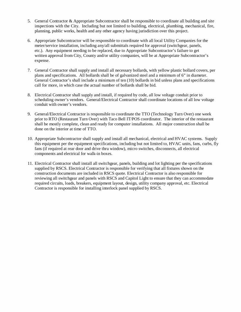
27. Plumbing Contractor shall verify location of water filter system and equipment served by filter.
28. General Contractor & Appropriate Subcontractors shall coordinate with the store manager on all miscellaneous wall hung items.
29. Tile/Flooring Contractor shall supply and install all tile, grout and material for tile work. Tile on
restroom walls shall be installed from floor to ceiling. Silicone all inside corners of all tile walls.
30. Drywall Contractor shall supply little orange peel texture on all drywalled walls and ceilings.
31. Finish Carpentry contractor shall supply and install four shelves in all closets, verify size and location with General Contractor. Shelving to be ¾” with white melamine finish.
32. Wood Framing Contractor shall install plywood sheeting on all walls except for the dining room. Solid
wood blocking shall be provided for wall-mounted equipment, accessories, fixtures, etc.
33. The drywall in the restrooms and any necessary drywall throughout the kitchen shall be water-resistant drywall.
34. Tile/Flooring Contractor shall provide a 1½” high tiled platform for the safe. Both front counter and
office safes to have platforms. Include 3/8” radius base and bullnosed cap tile. Safe shall be set in a bed of silicone and sealed to the platform.
35. General Contractor shall install all equipment into the restaurant including coordination of third party
vendor equipment.
36. Stucco/EIFS Contractor shall supply and install expansion joints approximately every 10’ when EIFS is used on the building. Reglet/expansion joints shall be used to separate all colors on color band, building and expression panels.
37. No foam trim/bands to be used on the exterior of building below 10’. Use only solid wood trim/bands
below 10’on exterior of building.
38. All handicap parking stalls, trash enclosure apron and drive thru lane shall be constructed of concrete.
39. There will be two or three Owner supplied sensor loops to be placed in the drive thru concrete by the Electrical Contractor. One in the drive-thru lane at the drive-thru window location, one in the drive-thru lane at the speaker post location and, if applicable, one in the drive thru lane at the pre-pay window (see site plan). It is the Electrical Contractor’s responsibility to correctly install the sensor loops at the depth required per installation instruction. Any/all loops that are installed to deep and do not operate correctly will be replaced by the Electrical Contractor at their expense.
40. HVAC Contractor shall supply and install full stainless steel wall caps and corner guards on all corners
in kitchen and traffic areas, including self-serve drink area. All stainless steel shall be hemmed or beveled at edges and sealed to the wall.

41. General Contractor shall supply and install roof hatch and roof ladder per specifications along with all city required handrails, ladderup bar, etc.
42. HVAC Contractor shall provide a mechanical test & balance report before turning over the restaurant.
Owner may have an independent consultant test & balance and commissioning on electrical, mechanical and plumbing systems in the restaurant in addition to the HVAC Contractor’s test & balance. This does not release the HVAC Contractor from providing a test and balance report. H V A C Contractor to verify all systems are running correctly prior to scheduling independent consultant for test & balance and commissioning. If not, HVAC Contractor will pay for additional trips for independent consultant to return.
43. Acoustic Ceiling Contractor shall silicone all ceiling grid to the walls/equipment.
44. Roofing Contractor shall supply and install single ply roofing. Single ply roofing shall be Duro-Last per
specifications. If approved by the Owner/Construction Manager, General Contractor may provide alternate pricing for Fibertite SM (45 mil) roofing. General Contractor to coordinate with Duro-Last to inspect and provide the Duro-Last certified warranty sticker on roof. This sticker shall have the Duro-Last warranty information.
45. Site-work/Paving/Concrete Contractor will be responsible to ensure that lot striping, handicap ramps
and all other ADA requirements (interior & exterior) are performed in accordance to all City, State and Federal ADA codes and laws.
46. An ADA inspection may be performed at the end of each project by an independent consultant. This
does not release the Site-work/Paving/Concrete Contractor from any liability of the ADA requirements.
47. General Contractor & Appropriate Subcontractors shall coordinate sign installations and make final
electrical connections for all project signage. Concrete Contractor is responsible for the foundations of the menu board, preview boards, speaker pedestal, clearance bar, drive-thru canopy, directional signs and any exterior menu board extenders. General Contractor to install the speaker post. Sign vendor to install all other drive-thru signage items. Sign vendor shall be responsible for pole or monument sign and foundations. Concrete bases shall be no lower than the top of the adjacent curb. Provide finished concrete on top and 8” down all sides of these foundations. Concrete Contractor shall provide drypack at base of all signage including menu board, speaker pedestal, drive-thru canopy, clearance bar, directional sign, monument/pole sign, etc.
48. Concrete Contractor shall be responsible to drypack the base of all lot light poles.
Please see attached Geotech Report from Terracon and Sheet T1.0 and Sheet A1.1 that are revised

Geotechnical Engineering ReportTaco Bell #310772
SEC of McCombs Avenue and US Highway 54El Paso, Texas
May 9, 2016Terracon Project No. 68165064
Prepared for:Taco Bell Corp.
Irvine, California
Prepared by:Terracon Consultants, Inc.
Las Cruces, New Mexico
Geotechnical Engineering ReportTaco Bell #310772 ■ El Paso, TexasMay 9, 2016 ■ Terracon Project No. 68165064
Responsive ■ Resourceful ■ Reliable i
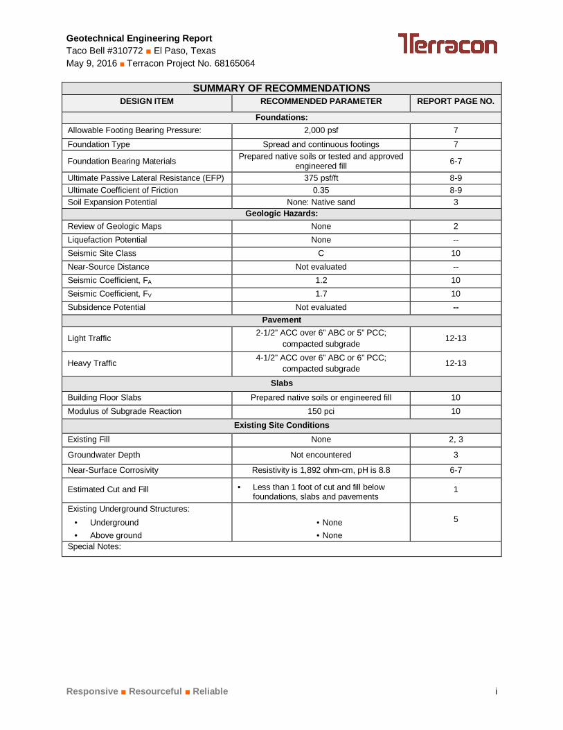
SUMMARY OF RECOMMENDATIONSDESIGN ITEM RECOMMENDED PARAMETER REPORT PAGE NO.
Foundations:Allowable Footing Bearing Pressure: 2,000 psf 7
Foundation Type Spread and continuous footings 7
Foundation Bearing Materials Prepared native soils or tested and approvedengineered fill 6-7
Ultimate Passive Lateral Resistance (EFP) 375 psf/ft 8-9Ultimate Coefficient of Friction 0.35 8-9Soil Expansion Potential None: Native sand 3
Geologic Hazards:Review of Geologic Maps None 2Liquefaction Potential None --Seismic Site Class C 10Near-Source Distance Not evaluated --Seismic Coefficient, FA 1.2 10Seismic Coefficient, FV 1.7 10Subsidence Potential Not evaluated --
Pavement
Light Traffic 2-1/2” ACC over 6” ABC or 5” PCC;compacted subgrade
12-13
Heavy Traffic 4-1/2” ACC over 6” ABC or 6” PCC;compacted subgrade 12-13
SlabsBuilding Floor Slabs Prepared native soils or engineered fill 10Modulus of Subgrade Reaction 150 pci 10
Existing Site ConditionsExisting Fill None 2, 3
Groundwater Depth Not encountered 3
Near-Surface Corrosivity Resistivity is 1,892 ohm-cm, pH is 8.8 6-7
Estimated Cut and Fill · Less than 1 foot of cut and fill belowfoundations, slabs and pavements
1
Existing Underground Structures:· Underground· Above ground
· None· None
5
Special Notes:

Geotechnical Engineering ReportTaco Bell #310772 ■ El Paso, TexasMay 9, 2016 ■ Terracon Project No. 68165064
Responsive ■ Resourceful ■ Reliable
TABLE OF CONTENTSPage
SUMMARY OF RECOMMENDATIONS ....................................................................................... i1.0 INTRODUCTION .............................................................................................................12.0 PROJECT INFORMATION .............................................................................................1
2.1 Project Description ...............................................................................................12.2 Site Location and Description...............................................................................2
3.0 SUBSURFACE CONDITIONS ........................................................................................23.1 Geology and Geologic Hazards ...........................................................................23.2 Typical Subsurface Profile ...................................................................................33.3 Groundwater ........................................................................................................3
4.0 RECOMMENDATIONS FOR DESIGN AND CONSTRUCTION ......................................44.1 Geotechnical Considerations ...............................................................................44.2 Earthwork.............................................................................................................4
4.2.1 Site Preparation ........................................................................................44.2.2 Fill Materials Types ...................................................................................54.2.3 Fill Material Placement and Compaction Requirements ............................54.2.4 Utility Trench Backfill ................................................................................54.2.5 Grading and Drainage ..............................................................................54.2.6 Earthwork Construction Considerations ....................................................64.2.7 Corrosion Potential ...................................................................................6
4.3 Foundation Recommendations and Trash Enclosure Walls .................................74.3.1 Foundation Design Recommendations .....................................................74.3.2 Foundation Construction Considerations ..................................................84.3.3 Pole Sign Spread Footing Foundation Additional DesignRecommendations ...............................................................................................84.3.4 Pole Sign Drilled Shaft Foundation Design Recommendations .................84.3.5 Pole Sign Drilled Shaft Foundation Construction Considerations ..............9
4.4 Seismic Considerations......................................................................................104.5 Floor Slabs.........................................................................................................10
4.5.1 Design Recommendations ......................................................................104.5.2 Floor Slab Construction Considerations ..................................................11
4.6 Lateral Earth Pressure .......................................................................................114.7 Pavements .........................................................................................................12
4.7.1 Design Recommendations ......................................................................124.7.2 Construction Considerations ...................................................................13
5.0 GENERAL COMMENTS ...............................................................................................14

Geotechnical Engineering ReportTaco Bell #310772 ■ El Paso, TexasMay 9, 2016 ■ Terracon Project No. 68165064
Responsive ■ Resourceful ■ Reliable
TABLE OF CONTENTS (cont.)
APPENDIX A – FIELD EXPLORATIONExhibit A-1 Site Location PlanExhibit A-2 Boring Location PlanExhibit A-3 Field Exploration DescriptionExhibits A-4 to A-8 Boring Logs
APPENDIX B – LABORATORY TESTINGExhibit B-1 Laboratory Testing DescriptionExhibit B-2 to B-4 Laboratory Testing Results
APPENDIX C – SUPPORTING DOCUMENTSExhibit C-1 General NotesExhibit C-2 Unified Soil Classification System


Responsive ■ Resourceful ■ Reliable 1
GEOTECHNICAL ENGINEERING REPORTTACO BELL #310772
SEC OF MCCOMBS AVENUE AND US HIGHWAY 54EL PASO, TEXAS
Terracon Project No. 68165064May 9, 2016
1.0 INTRODUCTION
This report presents the results of our geotechnical engineering services performed for theproposed Taco Bell to be located near the southeast corner of the McCombs Avenue and USHighway 54 intersection in El Paso, Texas. Five (5) borings, designated B-1 thru B-5, wereperformed to a depth of approximately 21-1/2 feet below the existing ground surface within theproposed building area, high rise, and parking areas. Logs of the borings along with a SiteLocation Plan and Boring Location Plan are included in Appendix A of this report.
The purpose of these services is to provide information and geotechnical engineeringrecommendations relative to:
n subsurface soil conditions n foundation design and constructionn earthworkn seismic considerations
n floor slab design and constructionn pavement design and construction
2.0 PROJECT INFORMATION
2.1 Project Description
Item Description
Site layout Refer to the Site Location Plan and Boring Location Plan (ExhibitsA-1 and A-2)
StructuresThe proposed project will include a single-story Taco BellRestaurant (approximately 2,000 square feet in ground contactarea). Parking and drive areas are associated with this project.
Building constructionTerracon assumes that the construction type for the building willconsist of steel stud and/or steel frame supported on spread andcontinuous footings.
Finished floor elevation (FFE) Anticipated to be less than 1 foot of cut and/or fill for final grade.

Geotechnical Engineering ReportTaco Bell #310772 ■ El Paso, TexasMay 6, 2016 ■ Terracon Project No. 68165064
Responsive ■ Resourceful ■ Reliable 2
Item Description
Maximum loadsColumns: 20 kips maximumWalls: 1.3 klf maximumSlabs: 110 psf max
Retaining walls None
TrafficDrive lanes – 1,000 cars and (5) 20,000-25,000 pound single-axleloadsParking – 50 cars/day/stall
2.2 Site Location and Description
Item DescriptionLocation SEC of McCombs Avenue and US Highway 54 in El Paso, TexasExisting site features Undeveloped, vacant land
Surrounding developments
North: Undeveloped/McCombs East PlazaWest: McCombs AvenueEast: Undeveloped/McCombs East PlazaSouth: Undeveloped/Rick Husband Drive
Current ground cover Exposed subgrade soils
Existing topography Relatively level
3.0 SUBSURFACE CONDITIONS
3.1 Geology and Geologic Hazards
Formation1 Description
Quaternary Alluvium Nearly level and gently sloping soils that have a clay loam subsoil andare moderately deep over caliche; in the Hueco Bolson.
1. Roadside Geology of Texas, Darwin Spearing, 1991.
Based on our review of USDA Soil Survey of El Paso County, Texas (dated 1971) the subjectsite is located in the Basin and Range Physiographic Province. The geology of the area ischaracterized by mountainous terrain with intervening basins. The site is located within theHueco Bolson, a low, down dropped structural area between the Franklin and Hueco Mountains.The sediments in the bolson are approximately 9,000 feet thick. The upper sediments consistmostly of stream-channel and flood plain deposits composed of silt, sand, gravel, and caliche.The deeper sediments are lacustrine (lake deposits) and are composed of silt and clay.

Geotechnical Engineering ReportTaco Bell #310772 ■ El Paso, TexasMay 6, 2016 ■ Terracon Project No. 68165064
Responsive ■ Resourceful ■ Reliable 3
3.2 Typical Subsurface Profile
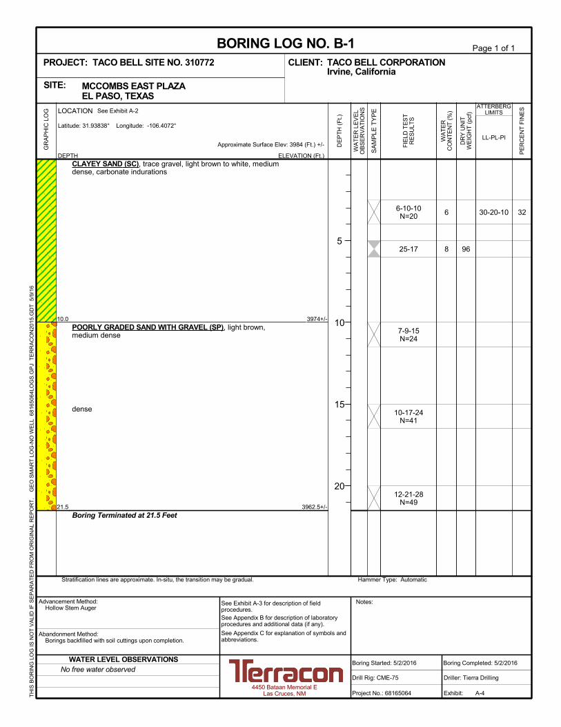
Specific conditions encountered at the boring locations are indicated on the individual boring logsincluded in Appendix A of this report. Stratification boundaries on the boring logs represent theapproximate location of changes in soil types; in-situ, the transition between materials may begradual. Based on the results of the boring, subsurface conditions on the project site can begeneralized as follows:
Description Approximate Depth toBottom of Stratum (feet) Material Encountered Consistency/Density
Stratum 1 10 to 15 Clayey Sand Medium Dense to Dense
Stratum 2 21-1/2Poorly Graded Sand with
GravelMedium Dense to Very
Dense
Laboratory test results indicate that the near surface soils exhibit low compressibility potentialsat in-situ moisture contents. The soils exhibit a moderate to high tendency for hydro-compactionwhen elevated in moisture content. Due to relatively high field penetration, low moisture contentand granular nature of the soils, the test results reflect sample disturbance. It is our opinion thatthe soils will exhibit low tendency for hydro-compaction when elevated in moisture content. Thesoils do not exhibit expansion under a surcharge load of 1,000 psf. Site soils were determinedto have a pH value of 8.8, a soluble sulfate value of 47 mg/Kg and minimum resistivity value of1,892 ohm-cm.
3.3 Groundwater
The borings were observed while drilling and after completion for the presence and level ofgroundwater. Groundwater was not observed in the borings while drilling, or for the short durationthat the borings were allowed to remain open. However, this does not necessarily mean theborings terminated above groundwater. Long term observations in piezometers or observationwells sealed from the influence of surface water are often required to define groundwater levels inmaterials of this type.
Groundwater level fluctuations occur due to seasonal variations in the amount of rainfall, runoffand other factors not evident at the time the borings were performed. Therefore, groundwaterlevels during construction or at other times in the life of the structure may be higher or lowerthan the levels indicated on the boring logs. The possibility of groundwater level fluctuationsshould be considered when developing the design and construction plans for the project.

Geotechnical Engineering ReportTaco Bell #310772 ■ El Paso, TexasMay 6, 2016 ■ Terracon Project No. 68165064
Responsive ■ Resourceful ■ Reliable 4
4.0 RECOMMENDATIONS FOR DESIGN AND CONSTRUCTION
4.1 Geotechnical Considerations
The site appears suitable for the proposed construction based upon geotechnical conditionsencountered in the test borings. Based on the geotechnical engineering analyses, subsurfaceexploration and laboratory test results, we recommend that the proposed building structure andtrash enclosure walls be supported by spread and continuous footings bearing on preparednative soils or engineered fill. The pole sign can be supported by a spread footing bearing onundisturbed native soils with a minimum embedment depth of 5 feet or as required by thestructural engineer. As an alternative, the pole sign can be supported on a drilled shaft with aminimum length of 8 feet or as required by the structural engineer. Slabs-on-grade can besupported by prepared native soils or engineered fill.
Geotechnical engineering recommendations for foundation systems and other earth connectedphases of the project are outlined below. The recommendations contained in this report arebased upon the results of field and laboratory testing (which are presented in Appendices A andB), engineering analyses, and our current understanding of the proposed project.
4.2 Earthwork
The following presents recommendations for site preparation, subgrade preparation, excavationand placement of engineered fills on the project. The recommendations presented for designand construction of earth supported elements including foundations, slabs and pavements arecontingent upon following the recommendations outlined in this section. All grading for thestructure should extend a minimum of five feet beyond proposed perimeter building walls.
Earthwork on the project should be observed and evaluated by Terracon. The evaluation ofearthwork should include observation and testing of engineered fill, subgrade preparation,foundation bearing soils, and other geotechnical conditions exposed during the construction ofthe project.
4.2.1 Site PreparationPrior to construction or placing any fill, all vegetation (if applicable), and any otherwiseunsuitable materials should be removed from the construction areas. Wet or dry materialshould either be removed, dried or moisture conditioned and compacted. Exposed areas whichwill receive fill or be constructed upon, once properly cleared, should be scarified to a minimumdepth of 10 inches, conditioned to near optimum moisture content, and compacted.
The site should be initially graded to create a relatively level surface to receive fill (if applicable)and to provide for a relatively uniform thickness of fill beneath the proposed building structure.

Geotechnical Engineering ReportTaco Bell #310772 ■ El Paso, TexasMay 6, 2016 ■ Terracon Project No. 68165064
Responsive ■ Resourceful ■ Reliable 5
Although evidence of underground facilities such as septic tanks, cesspools, utilities andbasements was not observed during the site reconnaissance, such features could beencountered during construction. If unexpected fills or underground facilities are encountered,such features should be removed and the excavation thoroughly cleaned prior to backfillplacement and/or construction.
4.2.2 Fill Material TypesEngineered fill should meet the following material property requirements:
Fill Type1 USCS Classification Acceptable Location for PlacementOn-Site Soils SC, SP All locations and elevations
Granular SM, SP, or SC2 All locations and elevations
1. Controlled, compacted fill should consist of approved materials that are free of organic matter anddebris. A sample of each material type should be submitted to the geotechnical engineer forevaluation.
2. Imported silty sand, poorly graded sand or clayey sand.
4.2.3 Fill Material Placement and Compaction RequirementsItem Description
Fill Lift Thickness 10 inches or less in loose thickness
Minimum Compaction Requirements 1 95% of the materials maximum modified Proctor drydensity (ASTM D 1557)
Moisture ContentWithin +/- 2% of optimum moisture content value asdetermined by the modified Proctor test at the timeof placement and compaction
2. We recommend that engineered fill be tested for moisture content and compaction duringplacement. Should the results of the in-place density tests indicate the specified moisture orcompaction limits have not been met, the area represented by the test should be reworked andretested as required until the specified moisture and compaction requirements are achieved.
4.2.4 Utility Trench BackfillAll trench excavations should be made with sufficient working space to permit constructionincluding backfill placement and compaction. If utility trenches are backfilled with relatively cleangranular material, they should be capped with at least 18 inches of cohesive fill in non-pavementareas to reduce the infiltration and conveyance of surface water through the trench backfill.
4.2.5 Grading and DrainagePositive drainage should be provided during construction and maintained throughout the life ofthe project. Infiltration of water into utility trenches or foundation excavations should beprevented during construction. Planters and other surface features which could retain water inareas adjacent to the building should be sealed or eliminated. In areas where sidewalks orpaving do not immediately adjoin the structure, we recommend that protective slopes be

Geotechnical Engineering ReportTaco Bell #310772 ■ El Paso, TexasMay 6, 2016 ■ Terracon Project No. 68165064
Responsive ■ Resourceful ■ Reliable 6
provided with a minimum grade of approximately 5 percent for at least 5 feet from perimeterwalls. Backfill against footings, exterior walls, and in utility and sprinkler line trenches should bewell compacted and free of all construction debris to reduce the possibility of moistureinfiltration.
Downspouts, roof drains or scuppers should discharge into splash blocks or extensions whenthe ground surface beneath such features is not protected by exterior slabs or paving. Sprinklersystems should not be installed within five feet of foundation walls. Landscaped irrigationadjacent to the foundation system should be minimized or eliminated.
4.2.6 Earthwork Construction ConsiderationsAlthough the exposed subgrade is anticipated to be relatively stable upon initial exposure, unstablesubgrade conditions could develop during general construction operations, particularly if the soilsare wetted and/or subjected to repetitive construction traffic. The use of light constructionequipment would aid in reducing subgrade disturbance. The use of remotely operated equipment,such as a backhoe, would be beneficial to perform cuts and reduce subgrade disturbance. Shouldunstable subgrade conditions develop, stabilization measures will need to be employed.
Upon completion of filling and grading, care should be taken to maintain the subgrade moisturecontent prior to construction of floor slabs and pavements. Construction traffic over thecompleted subgrade should be avoided to the extent practical. The site should also be gradedto prevent ponding of surface water on the prepared subgrades or in excavations. If thesubgrade should become desiccated, saturated, or disturbed, the affected material should beremoved or these materials should be scarified, moisture conditioned, and recompacted prior tofoundation, floor slab and pavement construction.
Temporary excavations will probably be required during construction operations. The gradingcontractor, by his contract, is usually responsible for designing and constructing stable,temporary excavations and should shore, slope or bench the sides of the excavations asrequired, to maintain stability of both the excavation sides and bottom. All excavations shouldcomply with applicable local, state and federal safety regulations, including the current OSHAExcavation and Trench Safety Standards.
The geotechnical engineer should be retained during the construction phase of the project toobserve earthwork and to perform necessary tests and observations during subgradepreparation; moisture conditioning; re-compaction; placement and compaction of controlledcompacted fills; backfilling of excavations into the completed subgrade, and just prior toconstruction of foundations, floor slabs and pavements.
4.2.7 Corrosion PotentialResults of corrosivity testing are provided in Appendix B. The results of soluble sulfate testing(47 mg/Kg) indicate that ASTM Type II Portland cement is warranted for concrete on and below

Geotechnical Engineering ReportTaco Bell #310772 ■ El Paso, TexasMay 6, 2016 ■ Terracon Project No. 68165064
Responsive ■ Resourceful ■ Reliable 7
grade. Foundation concrete should be designed in accordance with the provision of ACI DesignManual, Section 318, Chapter 4.
Laboratory test results indicate that on-site soils have a pH value of 8.8 and minimum resistivityof 1,892 ohm-centimeters. The pH and minimum resistivity values should be used to determinepotential corrosive characteristics of the on-site soils with respect to contact with the steel pipematerials that will be used for project construction. Values for pH and minimum resisitivity arecommonly used to help evaluate the corrosion potential of the soil with respect to buried metalsuch as metal utility pipes and CMP culverts. This and other information is typically analyzed bya corrosion specialist to determine site specific recommendations.
4.3 Foundation Recommendations and Trash Enclosure Walls
The building, trash enclosure walls, and pole sign structures can be supported by spread andcontinuous footings. Design recommendations for foundations for the proposed structures andrelated structural elements are presented in the following paragraphs.
4.3.1 Foundation Design RecommendationsDescription Value
Foundation Type Spread and Continuous Footings
Bearing Material Prepared native soils or engineered fill underlainby prepared native soils
Allowable Bearing Pressure 2,000 psf
Minimum Embedment Depth Below FinishedGrade
Building and Trash Enclosure Walls: 18 inchesPole Sign: 5 feet*
Total Estimated Settlement 1 inch
Estimated Differential Settlement ½ inch*Actual depth determined by the structural engineer
Finished grade is defined as the lowest adjacent grade within five feet of the foundation forperimeter (or exterior) footings and finished floor level for interior footings. The allowablefoundation bearing pressures apply to dead loads plus design live load conditions. The designbearing pressure may be increased by one-third when considering total loads that include windor seismic conditions. The weight of the foundation concrete below grade may be neglected indead load computations.
Footings should be proportioned to reduce differential foundation movement. Proportioning onthe basis of equal total movement is recommended; however, proportioning to relative constantdead-load pressure will also reduce differential movement between adjacent footings.Additional foundation movements could occur if water from any source infiltrates the foundationsoils; therefore, proper drainage must be provided in the final design and during construction.

Geotechnical Engineering ReportTaco Bell #310772 ■ El Paso, TexasMay 6, 2016 ■ Terracon Project No. 68165064
Responsive ■ Resourceful ■ Reliable 8
Footings, foundations, and masonry walls (if applicable) should be reinforced as necessary toreduce the potential for distress caused by differential foundation movement. The use of jointsat openings or other discontinuities in masonry walls is recommended.
Foundation excavations, subgrade preparation and engineered fill placement (if applicable)should be observed by the geotechnical engineer. If the soil conditions encountered differsignificantly from those presented in this report, supplemental recommendations will berequired.
4.3.2 Foundation Construction ConsiderationsPrepared native soils (minimum 10 inches in thickness) or engineered fill (if applicable) isrecommended below, and adjacent to the edges of all footings. The engineered fill shouldextend laterally an additional distance of 8 inches for each foot of excavation below the footings(if engineered fill is used). The engineered fill (if used) should extend horizontally a minimumdistance of 5 feet beyond the outside edge of perimeter footings.
4.3.3 Pole Sign Spread Footing Foundation Additional Design RecommendationsThe pole sign can be supported by a standard spread footing bearing on undisturbed nativesoils. To resist uplift loads on the pole sign, we recommend the foundations be embedded at aminimum depth of 5 feet below existing site grades; however, the actual depth should bedetermined by a structural engineer. The uplift forces should be resisted by the weight of thestructure, its foundation and the soil placed over the foundation. Additional resistance to upliftforces can be provided by either increasing the size of the footings or their depth below finalgrade. In either case, the resistance is increased by the addition of the soil weight over thefoundations. It is expected that the footings will be constructed such that the axial loads act atthe centroid of the footing, producing a compressive soil reaction everywhere beneath the baseof the foundation. Tension between the concrete and the soil should not be used in design. Foruplift consideration, the total weight of the concrete mass (at 145 pcf) divided by an appropriatefactor of safety could be used. The unit weight of soil above the footing can be taken as 120 pcffor design purposes when compacted as indicated in the Earthwork section of this report.
4.3.4 Pole Sign Drilled Shaft Foundation Design RecommendationsAs an alternative to the spread footing foundation, a drilled shaft can be used for support of thepole sign. Design recommendations for the drilled shaft are presented below:
Description ValueFoundation Type Drilled ShaftUnit Weight 115 pcfFriction Angle (φ) 32 degreesCohesion N/A

Geotechnical Engineering ReportTaco Bell #310772 ■ El Paso, TexasMay 6, 2016 ■ Terracon Project No. 68165064
Responsive ■ Resourceful ■ Reliable 9
Description ValueActive Rankine Coefficient (Ka) 0.30Passive Rankine Coefficient (Kp) 3.25Net Allowable End Bearing Pressure 8,000 psfAllowable Skin Friction 200 psfStatic Soil Modulus (k) 90 pciFactor of Safety 3Total Estimated Movement Less than 1 inchAllowable Passive Pressure 186 psf/ft (F.S. = 2)Ultimate Coefficient of Friction 0.35Recommended Minimum Shaft Length 8 feet*Recommended Minimum Shaft Diameter 24 inchesDepth of Frost Line 12 inches
*Actual depth determined by the structural engineer
For design, potential uplift and overturning forces can be resisted by dead load on each shaftplus the total axial capacity outlined above excluding end bearing resistance (skin friction only).
The soil modulus for the sands increases linearly with depth by an amount equal to thecoefficient of subgrade reaction. The soil moduli are ultimate values; therefore, appropriatefactors of safety should be applied in the shaft design.
The shaft should be reinforced full-depth for the applied axial, lateral and uplift stressesimposed. Minimum reinforcement of at least one percent of the cross-sectional area of the shaftshould be specified. For this project, use of a minimum shaft diameter of 24 inches isrecommended.
4.3.5 Pole Sign Drilled Shaft Foundation Construction ConsiderationsDrilling to design depth should be possible with conventional single flight power augers.However, the granular nature of the subsurface sand soils indicate that temporary steel casingor drilling slurry may be required to properly drill and clean shafts prior to concrete placement.Shaft concrete should be placed immediately after completion of drilling and cleaning. If shaftconcrete cannot be placed in dry conditions, a tremie should be used for concrete placement.Due to potential sloughing and raveling, foundation concrete quantities may exceed calculatedgeometric volumes.
If casing is used for shaft construction, it should be withdrawn in a slow continuous mannermaintaining a sufficient head of concrete to prevent the creation of voids in shaft concrete.Drilled shaft concrete should have a relatively high fluidity when placed in cased holes.Concrete with slump in the range of 6 to 8 inches is recommended.
Geotechnical Engineering ReportTaco Bell #310772 ■ El Paso, TexasMay 6, 2016 ■ Terracon Project No. 68165064
Responsive ■ Resourceful ■ Reliable 10
Free-fall concrete placement in drilled shafts will only be acceptable if provisions are taken toavoid striking the concrete on the sides of the hole or reinforcing steel. The use of a bottom-dump hopper or an elephant's trunk discharging near the bottom of the hole is recommended.
Shaft bearing surfaces must be cleaned prior to concrete placement. A geotechnical engineershould observe the soils and shaft configuration.
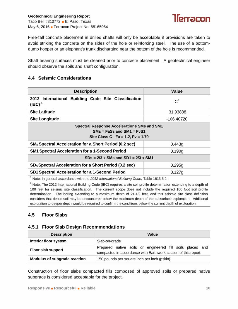
4.4 Seismic Considerations
Description Value2012 International Building Code Site Classification(IBC) 1 C2
Site Latitude 31.93838Site Longitude -106.40720
Spectral Response Accelerations SMs and SM1SMs = FaSs and SM1 = FvS1
Site Class C - Fa = 1.2, Fv = 1.70
SMS Spectral Acceleration for a Short Period (0.2 sec) 0.443gSM1 Spectral Acceleration for a 1-Second Period 0.190g
SDs = 2/3 x SMs and SD1 = 2/3 x SM1
SDS Spectral Acceleration for a Short Period (0.2 sec) 0.295gSD1 Spectral Acceleration for a 1-Second Period 0.127g1 Note: In general accordance with the 2012 International Building Code, Table 1613.5.2.2 Note: The 2012 International Building Code (IBC) requires a site soil profile determination extending to a depth of100 feet for seismic site classification. The current scope does not include the required 100 foot soil profiledetermination. The boring extending to a maximum depth of 21-1/2 feet, and this seismic site class definitionconsiders that dense soil may be encountered below the maximum depth of the subsurface exploration. Additionalexploration to deeper depth would be required to confirm the conditions below the current depth of exploration.
4.5 Floor Slabs
4.5.1 Floor Slab Design RecommendationsDescription Value
Interior floor system Slab-on-grade
Floor slab support Prepared native soils or engineered fill soils placed andcompacted in accordance with Earthwork section of this report.
Modulus of subgrade reaction 150 pounds per square inch per inch (psi/in)
Construction of floor slabs compacted fills composed of approved soils or prepared nativesubgrade is considered acceptable for the project.

Geotechnical Engineering ReportTaco Bell #310772 ■ El Paso, TexasMay 6, 2016 ■ Terracon Project No. 68165064
Responsive ■ Resourceful ■ Reliable 11
In areas of exposed concrete, control joints should be saw cut into the slab after concreteplacement in accordance with ACI Design Manual, Section 302.1R-37 8.3.12 (tooled controljoints are not recommended). Additionally, dowels should be placed at the location of proposedconstruction joints. To control the width of cracking (should it occur) continuous slabreinforcement should be considered in exposed concrete slabs.
Positive separations and/or isolation joints should be provided between slabs and allfoundations, columns or utility lines to allow independent movement. Interior trench backfillplaced beneath slabs should be compacted in accordance with recommendations outlined in theEarthwork section of this report. Other design and construction considerations, as outlined inthe ACI Design Manual, Section 302.1R are recommended.
4.5.2 Floor Slab Construction ConsiderationsPrepared native soils (minimum 10 inches in thickness) or engineered fill (if applicable) isrecommended below slabs-on-grade. The engineered fill (if used) should extend horizontally aminimum distance of 5 feet beyond the outside edge of perimeter footings. Some differentialmovement of a slab-on-grade floor system is possible should the subgrade soils becomeelevated in moisture content. To reduce potential slab movements, the subgrade soils shouldbe prepared as outlined above.
4.6 Lateral Earth Pressures
For soils above any free water surface, recommended equivalent fluid pressures forunrestrained foundation elements when using on-site clayey sand as backfill are:
· Active ...................................................................................... 35 psf/ft
· Passive ................................................................................. 375 psf/ft
· Coefficient of base friction ........................................................... 0.35*
*The coefficient of base friction should be reduced to 0.23 when used inconjunction with passive pressure.
Where the design includes restrained elements, the following equivalent fluid pressures arerecommended:
· At rest ..................................................................................... 54 psf/ft
The lateral earth pressures herein do not include any factor of safety and are not applicable forsubmerged soils/hydrostatic loading. Additional recommendations may be necessary if suchconditions are to be included in the design.

Geotechnical Engineering ReportTaco Bell #310772 ■ El Paso, TexasMay 6, 2016 ■ Terracon Project No. 68165064
Responsive ■ Resourceful ■ Reliable 12
Fill against foundations should be compacted to densities specified in the Earthwork section ofthis report. Compaction of each lift adjacent to walls should be accomplished withhand-operated tampers or other lightweight compactors. Overcompaction may cause excessivelateral earth pressures which could result in wall movement.
4.7 Pavements
4.7.1 Design RecommendationsDesign of pavements for the project have been based on the procedures outlined in the Designof Hot Mix Asphalt Pavements by the National Asphalt Pavement Association (NAPA).Calculated traffic criteria (based on client provided information) used for pavement thicknessdesign includes single 18-kip equivalent standard axle loads (ESAL's) of 14,600 for plannedauto parking areas and 73,000 for truck access and drives. Actual design traffic loading shouldbe verified. Reevaluation of the recommended pavement sections may be necessary if theactual traffic varies from the assumed criteria outlined above. Recommended alternatives forflexible and rigid pavements, summarized for each traffic area, are as follows:
Traffic Area Alternative
Recommended Pavement Section Thickness (inches)Asphalt
ConcreteSurface
PortlandCement
Concrete
AggregateBase
CourseTotal
Parking andAutomobile
Parking Areas
A 2-1/2 --- 6 8-1/2
B --- 5 --- 5
Truck Accessand Drives
A 4-1/2 --- 6 10-1/2
B --- 6 --- 6
Each alternative should be investigated with respect to current material availability andeconomic conditions. Rigid concrete pavement, a minimum of 6 inches in thickness, isrecommended at the location of dumpsters where trash trucks will park and load or areas ofanticipated heavy vehicle loads.
Concrete construction and placement for the parking and drive areas (i.e. curb and gutter,drainage ditches, etc.) should be in accordance with the Texas Department of Transportation(TXDOT) guidelines.
Aggregate base course should consist of a blend of sand and gravel which meets strictspecifications for quality and gradation. TXDOT specifications are to be used for the pavementconstruction.

Geotechnical Engineering ReportTaco Bell #310772 ■ El Paso, TexasMay 6, 2016 ■ Terracon Project No. 68165064
Responsive ■ Resourceful ■ Reliable 13
The asphaltic concrete surface course should be plant mixed, hot laid Type C or D Surfacemeeting the master specifications requirements of 2004 TXDOT Standard Specifications Item340, pages 265 through 278, and specific criteria for the job mix formula.
Asphalt material should be placed in maximum 3-inch lifts and should be compacted to aminimum of 93% Maximum Theoretical Density (AASHTO T-209). In addition to the flexiblepavement design analyses, a rigid pavement design analysis was completed for each trafficcategory, based upon AASHTO design procedures.
Recommendations for pavement construction presented depend upon compliance withrecommended material specifications. To assess compliance, observation and testing shouldbe performed under the direction of the geotechnical engineer.
4.7.2 Construction ConsiderationsPavement design methods are intended to provide structural sections with adequate thicknessover a particular subgrade such that wheel loads are reduced to a level the subgrade cansupport. The support characteristics of the subgrade for pavement design do not account forsettlement induced movements of subgrade such as the soils encountered on this project.Thus, the pavement may be adequate from a structural standpoint, yet still experience crackingand deformation due to settlement related movement of the subgrade. It is, therefore, importantto minimize moisture changes in the subgrade to reduce settlement.
Minimizing subgrade saturation is an important factor in maintaining subgrade strength andstability. Some distress of pavements is possible due to the sand subgrade soils. Waterallowed to pond on or adjacent to pavements could saturate the subgrade and cause prematurepavement deterioration. The pavement should be sloped to provide rapid surface drainage, andpositive surface drainage should be maintained away from the edge of the paved areas. Designalternatives which could reduce the risk of subgrade saturation and improve long-termpavement performance include crowning the pavement subgrades to drain toward the edges,rather than to the center of the pavement areas; and installing surface drains next to any areaswhere surface water could pond. Properly designed and constructed subsurface drainage willreduce the time subgrade soils are saturated and can also improve subgrade strength andperformance.
Periodic maintenance extends the service life of the pavement and should include crack sealing,surface sealing and patching of any deteriorated areas. Also, thicker pavement sections couldbe used to reduce the required maintenance and extend the service life of the pavement. Ifasphaltic concrete is used for this project, we recommend that reinforced concrete pads beprovided in front of and beneath trash receptacles. The dumpster trucks should be parked onthe rigid concrete pavement when the trash receptacles are lifted. The concrete pads at andadjacent to the trash enclosure should be a minimum of 6 inches thick and properly reinforced.

Geotechnical Engineering ReportTaco Bell #310772 ■ El Paso, TexasMay 6, 2016 ■ Terracon Project No. 68165064
Responsive ■ Resourceful ■ Reliable 14
The performance of all pavements can be enhanced by minimizing excess moisture which canreach the subgrade soils. The following recommendations should be considered at minimum:
n site grading at a minimum 2 percent grade away from the pavements.n the subgrade and the pavement surface have a minimum 1/4 inch per foot slope to
promote proper surface drainage.n consider appropriate edge drainage and pavement underdrain systems.n install pavement drainage surrounding areas anticipated for frequent wetting.n install joint sealant and seal cracks immediately.n compaction of any utility trenches for landscaped areas to the same criteria as the
pavement subgrade.n seal all landscaped areas in or adjacent to pavements to minimize or prevent moisture
migration to subgrade soils.n place compacted, low permeability backfill against the exterior side of curb and gutter.
5.0 GENERAL COMMENTS
Terracon should be retained to review the final design plans and specifications so commentscan be made regarding interpretation and implementation of our geotechnical recommendationsin the design and specifications. Terracon also should be retained to provide observation andtesting services during grading, excavation, foundation construction and other earth-relatedconstruction phases of the project.
The analysis and recommendations presented in this report are based upon the data obtainedfrom the boring performed at the indicated locations and from other information discussed in thisreport. This report does not reflect variations that may occur between boring, across the site, ordue to the modifying effects of construction or weather. The nature and extent of suchvariations may not become evident until during or after construction. If variations appear, weshould be immediately notified so that further evaluation and supplemental recommendationscan be provided.
The scope of services for this project does not include either specifically or by implication anyenvironmental or biological (e.g., mold, fungi, bacteria) assessment of the site or identification orprevention of pollutants, hazardous materials or conditions. If the owner is concerned about thepotential for such contamination or pollution, other studies should be undertaken.
This report has been prepared for the exclusive use of our client for specific application to theproject discussed and has been prepared in accordance with generally accepted geotechnicalengineering practices. No warranties, either express or implied, are intended or made. Sitesafety, excavation support, and dewatering requirements are the responsibility of others. In theevent that changes in the nature, design, or location of the project as outlined in this report are

Geotechnical Engineering ReportTaco Bell #310772 ■ El Paso, TexasMay 6, 2016 ■ Terracon Project No. 68165064
Responsive ■ Resourceful ■ Reliable 15
planned, the conclusions and recommendations contained in this report shall not be consideredvalid unless Terracon reviews the changes and either verifies or modifies the conclusions of thisreport in writing.

APPENDIX A
FIELD EXPLORATION

SITE LOCATION PLAN
TB Site No. 310772-ELPSEC Hwy 54 & McCombs
El Paso, TX
TOPOGRAPHIC MAP IMAGE COURTESY OF THE U.S. GEOLOGICAL SURVEYQUADRANGLES INCLUDE: NORTH FRANKLIN MOUNTAIN, TX (1/1/1995).
4450 Bataan Memorial ELas Cruces, NM 88011-6000
68165064Project Manager:
Drawn by:
Checked by:
Approved by:
DB
JDC
JDC
1”=2,000’
Figures
4/29/16
Project No.
Scale:
File Name:
Date:A-1
ExhibitDB

BORING LOCATION PLAN
TB Site No. 310772-ELPSEC Hwy 54 & McCombs
El Paso, TX4450 Bataan Memorial E
Las Cruces, NM 88011-6000
DIAGRAM IS FOR GENERAL LOCATION ONLY, AND ISNOT INTENDED FOR CONSTRUCTION PURPOSES
68165064
AERIAL PHOTOGRAPHY PROVIDEDBY MICROSOFT BING MAPS
DB
JDC
JDC
AS SHOWN
Figures
4/29/16
Scale:
A-2
ExhibitProject Manager:
Drawn by:
Checked by:
Approved by:
Project No.
File Name:
Date:
DB
B-1
Approximate Boring Location
B-2
B-3B-4B-5
Rick Husband Dr.M
cCom
bsA
ve.

Geotechnical Engineering ReportTaco Bell #310772 ■ El Paso, TexasMay 9, 2016 ■ Terracon Project No. 68165064
Responsive ■ Resourceful ■ Reliable Exhibit A-3
Field Exploration Description
Five (5) test borings were drilled at the site on May 2, 2015. The borings were drilled to a depthof about 21-1/2 feet below the ground surface at the approximate locations shown on theattached Boring Location Plan, Exhibit A-2. The test borings are located as follows:
Boring Location Depth (feet)B-1 and B-2 Building Footprint 21-1/2
B-3 Trash Enclosure 21-1/2
B-4 Parking and Drive Areas 21-1/2
B-5 Pole Sign 21-1/2
The test borings were advanced with a truck-mounted CME-75 drill rig utilizing 8-inch diameterhollow-stem augers.
The borings were located in the field by using the proposed site plan and an aerial photographof the site, and measuring from existing property lines. The accuracy of boring locations shouldonly be assumed to the level implied by the method used. Latitude, longitude and elevationsusing a hand-held GPS unit are provided on the boring logs in the appendix of this report.
Lithologic logs of the borings were recorded by the field geologist during the drilling operations.At selected intervals, samples of the subsurface materials were taken by driving split-spoon orring-barrel samplers. Bulk samples of subsurface materials were also obtained.
Penetration resistance measurements were obtained by driving the split-spoon and ring-barrelsamplers into the subsurface materials with a 140-pound automatic hammer falling 30 inches.The penetration resistance value is a useful index in estimating the consistency or relativedensity of materials encountered.
A CME automatic SPT hammer was used to advance the split-barrel sampler in the boringperformed on this site. The effect of the automatic hammer's efficiency has been considered inthe interpretation and analysis of the subsurface information for this report.
Groundwater conditions were evaluated in the boring at the time of site exploration.
326
8 96
30-20-10
3974+/-
3962.5+/-
6-10-10N=20
25-17
7-9-15N=24
10-17-24N=41
12-21-28N=49
10.0
21.5
CLAYEY SAND (SC), trace gravel, light brown to white, mediumdense, carbonate indurations
POORLY GRADED SAND WITH GRAVEL (SP), light brown,medium dense
dense
Boring Terminated at 21.5 Feet
Hammer Type: AutomaticStratification lines are approximate. In-situ, the transition may be gradual.
GR
AP
HIC
LO
G
TH
IS B
OR
ING
LO
G IS
NO
T V
ALI
D IF
SE
PA
RA
TE
D F
RO
M O
RIG
INA
L R
EP
OR
T.
G
EO
SM
AR
T L
OG
-NO
WE
LL 6
816
506
4LO
GS
.GP
J T
ER
RA
CO
N20
15.G
DT
5/9
/16
SITE:
Page 1 of 1
Advancement Method:Hollow Stem Auger
Abandonment Method:Borings backfilled with soil cuttings upon completion.
4450 Bataan Memorial ELas Cruces, NM
Notes:
Project No.: 68165064
Drill Rig: CME-75
Boring Started: 5/2/2016
BORING LOG NO. B-1TACO BELL CORPORATIONCLIENT:Irvine, California
Driller: Tierra Drilling
Boring Completed: 5/2/2016
Exhibit: A-4
See Exhibit A-3 for description of fieldprocedures.See Appendix B for description of laboratoryprocedures and additional data (if any).
See Appendix C for explanation of symbols andabbreviations.
MCCOMBS EAST PLAZA EL PASO, TEXAS
PROJECT: TACO BELL SITE NO. 310772
PE
RC
EN
T F
INE
S
WA
TE
RC
ON
TE
NT
(%
)
DR
Y U
NIT
WE
IGH
T (
pcf)
ATTERBERGLIMITS
LL-PL-PI Approximate Surface Elev: 3984 (Ft.) +/-
ELEVATION (Ft.)
SA
MP
LE T
YP
E
WA
TE
R L
EV
EL
OB
SE
RV
AT
ION
S
DE
PT
H (
Ft.)
5
10
15
20
FIE
LD T
ES
TR
ES
ULT
S
DEPTH
LOCATION See Exhibit A-2
Latitude: 31.93838° Longitude: -106.4072°
No free water observedWATER LEVEL OBSERVATIONS

3974+/-
3962.5+/-
10-12-15N=27
29-20
10-15-18N=33
13-26-23N=49
14-23-27N=50
10.0
21.5
CLAYEY SAND (SC), trace gravel, light brown to white, mediumdense, carbonate indurations
POORLY GRADED SAND WITH GRAVEL (SP), light brown, dense
very dense
Boring Terminated at 21.5 Feet
Hammer Type: AutomaticStratification lines are approximate. In-situ, the transition may be gradual.
GR
AP
HIC
LO
G
TH
IS B
OR
ING
LO
G IS
NO
T V
ALI
D IF
SE
PA
RA
TE
D F
RO
M O
RIG
INA
L R
EP
OR
T.
G
EO
SM
AR
T L
OG
-NO
WE
LL 6
816
506
4LO
GS
.GP
J T
ER
RA
CO
N20
15.G
DT
5/9
/16
SITE:
Page 1 of 1
Advancement Method:Hollow Stem Auger
Abandonment Method:Borings backfilled with soil cuttings upon completion.
4450 Bataan Memorial ELas Cruces, NM
Notes:
Project No.: 68165064
Drill Rig: CME-75
Boring Started: 5/2/2016
BORING LOG NO. B-2TACO BELL CORPORATIONCLIENT:Irvine, California
Driller: Tierra Drilling
Boring Completed: 5/2/2016
Exhibit: A-5
See Exhibit A-3 for description of fieldprocedures.See Appendix B for description of laboratoryprocedures and additional data (if any).
See Appendix C for explanation of symbols andabbreviations.
MCCOMBS EAST PLAZA EL PASO, TEXAS
PROJECT: TACO BELL SITE NO. 310772
PE
RC
EN
T F
INE
S
WA
TE
RC
ON
TE
NT
(%
)
DR
Y U
NIT
WE
IGH
T (
pcf)
ATTERBERGLIMITS
LL-PL-PI Approximate Surface Elev: 3984 (Ft.) +/-
ELEVATION (Ft.)
SA
MP
LE T
YP
E
WA
TE
R L
EV
EL
OB
SE
RV
AT
ION
S
DE
PT
H (
Ft.)
5
10
15
20
FIE
LD T
ES
TR
ES
ULT
S
DEPTH
LOCATION See Exhibit A-2
Latitude: 31.93845° Longitude: -106.40701°
No free water observedWATER LEVEL OBSERVATIONS

41 NP
3973+/-
3961.5+/-
10-16-16N=32
10-10-12N=22
8-11-15N=26
12-20-19N=39
12-22-23N=45
10.0
21.5
CLAYEY SAND (SC), trace gravel, light brown to white, dense,carbonate indurations
medium dense
POORLY GRADED SAND WITH GRAVEL (SP), light brown,medium dense
dense
Boring Terminated at 21.5 Feet
Hammer Type: AutomaticStratification lines are approximate. In-situ, the transition may be gradual.
GR
AP
HIC
LO
G
TH
IS B
OR
ING
LO
G IS
NO
T V
ALI
D IF
SE
PA
RA
TE
D F
RO
M O
RIG
INA
L R
EP
OR
T.
G
EO
SM
AR
T L
OG
-NO
WE
LL 6
816
506
4LO
GS
.GP
J T
ER
RA
CO
N20
15.G
DT
5/9
/16
SITE:
Page 1 of 1
Advancement Method:Hollow Stem Auger
Abandonment Method:Borings backfilled with soil cuttings upon completion.
4450 Bataan Memorial ELas Cruces, NM
Notes:
Project No.: 68165064
Drill Rig: CME-75
Boring Started: 5/2/2016
BORING LOG NO. B-3TACO BELL CORPORATIONCLIENT:Irvine, California
Driller: Tierra Drilling
Boring Completed: 5/2/2016
Exhibit: A-6
See Exhibit A-3 for description of fieldprocedures.See Appendix B for description of laboratoryprocedures and additional data (if any).
See Appendix C for explanation of symbols andabbreviations.
MCCOMBS EAST PLAZA EL PASO, TEXAS
PROJECT: TACO BELL SITE NO. 310772
PE
RC
EN
T F
INE
S
WA
TE
RC
ON
TE
NT
(%
)
DR
Y U
NIT
WE
IGH
T (
pcf)
ATTERBERGLIMITS
LL-PL-PI Approximate Surface Elev: 3983 (Ft.) +/-
ELEVATION (Ft.)
SA
MP
LE T
YP
E
WA
TE
R L
EV
EL
OB
SE
RV
AT
ION
S
DE
PT
H (
Ft.)
5
10
15
20
FIE
LD T
ES
TR
ES
ULT
S
DEPTH
LOCATION See Exhibit A-2
Latitude: 31.93819° Longitude: -106.40685°
No free water observedWATER LEVEL OBSERVATIONS

328 30-18-12
3974+/-
3962.5+/-
7-10-13N=23
13-16-15N=31
8-10-16N=26
11-21-22N=43
14-19-20N=39
10.0
21.5
CLAYEY SAND (SC), trace gravel, light brown to white, mediumdense, carbonate indurations
dense
POORLY GRADED SAND WITH GRAVEL (SP), light brown,medium dense
dense
Boring Terminated at 21.5 Feet
Hammer Type: AutomaticStratification lines are approximate. In-situ, the transition may be gradual.
GR
AP
HIC
LO
G
TH
IS B
OR
ING
LO
G IS
NO
T V
ALI
D IF
SE
PA
RA
TE
D F
RO
M O
RIG
INA
L R
EP
OR
T.
G
EO
SM
AR
T L
OG
-NO
WE
LL 6
816
506
4LO
GS
.GP
J T
ER
RA
CO
N20
15.G
DT
5/9
/16
SITE:
Page 1 of 1
Advancement Method:Hollow Stem Auger
Abandonment Method:Borings backfilled with soil cuttings upon completion.
4450 Bataan Memorial ELas Cruces, NM
Notes:
Project No.: 68165064
Drill Rig: CME-75
Boring Started: 5/2/2016
BORING LOG NO. B-4TACO BELL CORPORATIONCLIENT:Irvine, California
Driller: Tierra Drilling
Boring Completed: 5/2/2016
Exhibit: A-7
See Exhibit A-3 for description of fieldprocedures.See Appendix B for description of laboratoryprocedures and additional data (if any).
See Appendix C for explanation of symbols andabbreviations.
MCCOMBS EAST PLAZA EL PASO, TEXAS
PROJECT: TACO BELL SITE NO. 310772
PE
RC
EN
T F
INE
S
WA
TE
RC
ON
TE
NT
(%
)
DR
Y U
NIT
WE
IGH
T (
pcf)
ATTERBERGLIMITS
LL-PL-PI Approximate Surface Elev: 3984 (Ft.) +/-
ELEVATION (Ft.)
SA
MP
LE T
YP
E
WA
TE
R L
EV
EL
OB
SE
RV
AT
ION
S
DE
PT
H (
Ft.)
5
10
15
20
FIE
LD T
ES
TR
ES
ULT
S
DEPTH
LOCATION See Exhibit A-2
Latitude: 31.93818° Longitude: -106.40717°
No free water observedWATER LEVEL OBSERVATIONS

357 30-16-14
3971+/-
3964.5+/-
16-12-11N=23
5-11-16N=27
4-7-7N=14
10-18-16N=34
14-18-18N=36
15.0
21.5
CLAYEY SAND (SC), trace gravel, light brown to white, mediumdense, carbonate indurations
POORLY GRADED SAND WITH GRAVEL (SP), light brown, dense
Boring Terminated at 21.5 Feet
Hammer Type: AutomaticStratification lines are approximate. In-situ, the transition may be gradual.
GR
AP
HIC
LO
G
TH
IS B
OR
ING
LO
G IS
NO
T V
ALI
D IF
SE
PA
RA
TE
D F
RO
M O
RIG
INA
L R
EP
OR
T.
G
EO
SM
AR
T L
OG
-NO
WE
LL 6
816
506
4LO
GS
.GP
J T
ER
RA
CO
N20
15.G
DT
5/9
/16
SITE:
Page 1 of 1
Advancement Method:Hollow Stem Auger
Abandonment Method:Borings backfilled with soil cuttings upon completion.
4450 Bataan Memorial ELas Cruces, NM
Notes:
Project No.: 68165064
Drill Rig: CME-75
Boring Started: 5/2/2016
BORING LOG NO. B-5TACO BELL CORPORATIONCLIENT:Irvine, California
Driller: Tierra Drilling
Boring Completed: 5/2/2016
Exhibit: A-8
See Exhibit A-3 for description of fieldprocedures.See Appendix B for description of laboratoryprocedures and additional data (if any).
See Appendix C for explanation of symbols andabbreviations.
MCCOMBS EAST PLAZA EL PASO, TEXAS
PROJECT: TACO BELL SITE NO. 310772
PE
RC
EN
T F
INE
S
WA
TE
RC
ON
TE
NT
(%
)
DR
Y U
NIT
WE
IGH
T (
pcf)
ATTERBERGLIMITS
LL-PL-PI Approximate Surface Elev: 3986 (Ft.) +/-
ELEVATION (Ft.)
SA
MP
LE T
YP
E
WA
TE
R L
EV
EL
OB
SE
RV
AT
ION
S
DE
PT
H (
Ft.)
5
10
15
20
FIE
LD T
ES
TR
ES
ULT
S
DEPTH
LOCATION See Exhibit A-2
Latitude: 31.93819° Longitude: -106.4074°
No free water observedWATER LEVEL OBSERVATIONS

APPENDIX B
LABORATORY TESTING

Geotechnical Engineering ReportTaco Bell #310772 ■ El Paso, TexasMay 9, 2016 ■ Terracon Project No. 68165064
Responsive ■ Resourceful ■ Reliable Exhibit B-1
Laboratory Testing
Soil samples were tested in the laboratory to measure their dry unit weight and natural watercontent. Grain size analyses, pH, compression, soluble sulfate and resistivity testing were alsoperformed on selected samples. The test results are provided on the boring logs and presentedin Appendix B.
Descriptive classifications of the soils indicated on the boring logs are in accordance with theenclosed General Notes and the Unified Soil Classification System. Also shown are estimatedUnified Soil Classification Symbols. A brief description of this classification system is attachedto this report in Appendix C. All classification was by visual/manual procedures, (ASTM D2487).Selected samples were further classified using the results of Atterberg limit testing, (ASTMD4318). The Atterberg limit test results are also provided on the boring logs.
Procedural standards noted above are for reference to methodology in general. In some cases,variations to methods are applied as a result of local practice or professional judgment.

0
5
10
15
20
25
30
35
40
45
50
55
60
65
70
75
80
85
90
95
100
0.0010.010.1110100
B-1
B-3
B-4
B-5
30
NP
30
30
0.609
0.286
2.993
0.232
0.221
19
25
12.5
25
6 16 20 30 40 501.5 2006 810
8.8
30.8
3.4
11.8
0.187
14
32.4
3.5
32.4
34.9
%Fines
LL PL PI
41 3/4 1/2 60
fine
B-1
B-3
B-4
B-5
15.99
GRAIN SIZE IN MILLIMETERS
PE
RC
EN
T F
INE
R B
Y W
EIG
HT
coarse fine
HYDROMETERU.S. SIEVE OPENING IN INCHES U.S. SIEVE NUMBERS
20
NP
18
16
10
NP
12
14
0.66
D100
Cc Cu
SILT OR CLAY
4
%Sand%GravelD30 D10
2.5 - 4
10 - 11.5
2.5 - 4
5 - 6.5
3/8 3 100 1403 2
COBBLESGRAVEL SAND
USCS Classification
58.8
65.7
64.2
53.3
D60
coarse medium
Boring ID Depth
Boring ID Depth
GRAIN SIZE DISTRIBUTION
2.5 - 4
10 - 11.5
2.5 - 4
5 - 6.5
CLAYEY SAND (SC)
POORLY GRADED SAND with GRAVEL (SP)
CLAYEY SAND (SC)
CLAYEY SAND (SC)
ASTM D422 / ASTM C136
4450 Bataan Memorial ELas Cruces, NM
PROJECT NUMBER: 68165064PROJECT: TACO BELL SITE NO. 310772
SITE: MCCOMBS EAST PLAZA EL PASO, TEXAS
CLIENT: TACO BELL CORPORATION Irvine, California
EXHIBIT: B-2
LAB
OR
AT
OR
Y T
ES
TS
AR
E N
OT
VA
LID
IF S
EP
AR
AT
ED
FR
OM
OR
IGIN
AL
RE
PO
RT
.
GR
AIN
SIZ
E: U
SC
S-2
681
650
64L
OG
S.G
PJ
351
5909
7 -
AT
TE
RB
ER
G IS
SU
E.G
PJ
5/9
/16

TACO BELL SITE #310772EL PASO, TEXAS TERRACON
4450 BATAAN MEMORIAL EASTLAS CRUCES, NEW MEXICO 88011
(575) 527-1700fax (575) 527-1092
CONSOL-B-1@ 5'.xls
BORING B-1 @ 5'CLAYEY SAND
USCS Classification:SC
DRY DENSITY= 96 lbs/ft3
MOISTURE CONTENT=7.7%
PROJECT NO. 68165064
-7
-6
-5
-4
-3
-2
-1
0
10 100 1000 10000
PER
CE
NT
CO
NSO
LID
ATIO
N/S
WEL
L
STRESS POUNDS PER SQUARE FOOT
SWELL/CONSOLIDATION CHART
water added
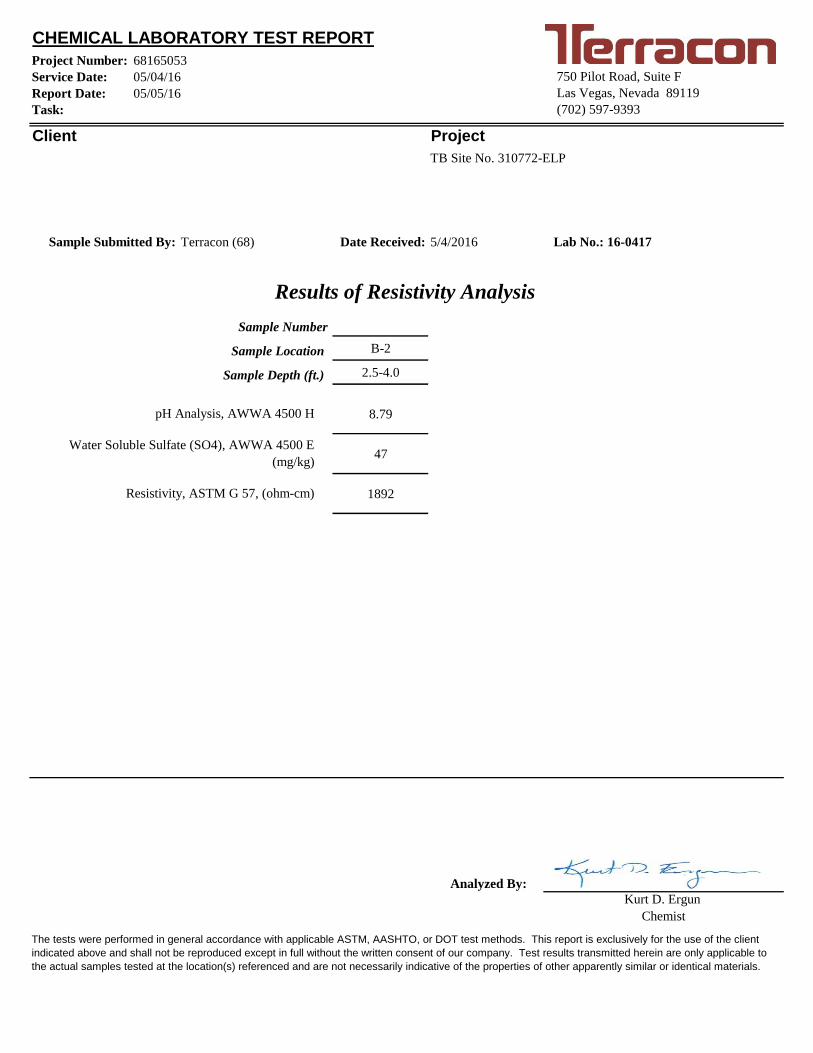
Project Number:
Service Date:
Report Date:
Task:
Client
Date Received:
B-2
2.5-4.0
8.79
47
1892
Analyzed By:
CHEMICAL LABORATORY TEST REPORT
Kurt D. Ergun
pH Analysis, AWWA 4500 H
Water Soluble Sulfate (SO4), AWWA 4500 E
(mg/kg)
Resistivity, ASTM G 57, (ohm-cm)
TB Site No. 310772-ELP
05/05/16
750 Pilot Road, Suite F
Las Vegas, Nevada 89119
(702) 597-9393
Project
Lab No.: 16-0417
Sample Number
Sample Location
Sample Depth (ft.)
The tests were performed in general accordance with applicable ASTM, AASHTO, or DOT test methods. This report is exclusively for the use of the client
indicated above and shall not be reproduced except in full without the written consent of our company. Test results transmitted herein are only applicable to
the actual samples tested at the location(s) referenced and are not necessarily indicative of the properties of other apparently similar or identical materials.
68165053
Terracon (68)Sample Submitted By: 5/4/2016
Results of Resistivity Analysis
Chemist
05/04/16

APPENDIX CSUPPORTING DOCUMENTS


Exhibit C-2
UNIFIED SOIL CLASSIFICATION SYSTEM
Criteria for Assigning Group Symbols and Group Names Using Laboratory Tests A
Soil Classification
Group
Symbol Group Name
B
Coarse Grained Soils:
More than 50% retained
on No. 200 sieve
Gravels:
More than 50% of
coarse fraction retained
on No. 4 sieve
Clean Gravels:
Less than 5% fines C
Cu 4 and 1 Cc 3 E
GW Well-graded gravel F
Cu 4 and/or 1 Cc 3 E
GP Poorly graded gravel F
Gravels with Fines:
More than 12% fines C
Fines classify as ML or MH GM Silty gravel F,G,H
Fines classify as CL or CH GC Clayey gravel F,G,H
Sands:
50% or more of coarse
fraction passes No. 4
sieve
Clean Sands:
Less than 5% fines D
Cu 6 and 1 Cc 3 E
SW Well-graded sand I
Cu 6 and/or 1 Cc 3 E
SP Poorly graded sand I
Sands with Fines:
More than 12% fines D
Fines classify as ML or MH SM Silty sand G,H,I
Fines classify as CL or CH SC Clayey sand G,H,I
Fine-Grained Soils:
50% or more passes the
No. 200 sieve
Silts and Clays:
Liquid limit less than 50
Inorganic: PI 7 and plots on or above “A” line
J CL Lean clay
K,L,M
PI 4 or plots below “A” line J ML Silt
K,L,M
Organic: Liquid limit - oven dried
0.75 OL Organic clay
K,L,M,N
Liquid limit - not dried Organic silt K,L,M,O
Silts and Clays:
Liquid limit 50 or more
Inorganic: PI plots on or above “A” line CH Fat clay
K,L,M
PI plots below “A” line MH Elastic Silt K,L,M
Organic: Liquid limit - oven dried
0.75 OH Organic clay
K,L,M,P
Liquid limit - not dried Organic silt K,L,M,Q
Highly organic soils: Primarily organic matter, dark in color, and organic odor PT Peat
A Based on the material passing the 3-inch (75-mm) sieve
B If field sample contained cobbles or boulders, or both, add “with cobbles
or boulders, or both” to group name. C
Gravels with 5 to 12% fines require dual symbols: GW-GM well-graded
gravel with silt, GW-GC well-graded gravel with clay, GP-GM poorly
graded gravel with silt, GP-GC poorly graded gravel with clay. D
Sands with 5 to 12% fines require dual symbols: SW-SM well-graded
sand with silt, SW-SC well-graded sand with clay, SP-SM poorly graded
sand with silt, SP-SC poorly graded sand with clay
E Cu = D60/D10 Cc =
6010
2
30
DxD
)(D
F If soil contains 15% sand, add “with sand” to group name.
G If fines classify as CL-ML, use dual symbol GC-GM, or SC-SM.
H If fines are organic, add “with organic fines” to group name.
I If soil contains 15% gravel, add “with gravel” to group name.
J If Atterberg limits plot in shaded area, soil is a CL-ML, silty clay.
K If soil contains 15 to 29% plus No. 200, add “with sand” or “with gravel,”
whichever is predominant. L
If soil contains 30% plus No. 200 predominantly sand, add “sandy” to
group name. M
If soil contains 30% plus No. 200, predominantly gravel, add
“gravelly” to group name. N
PI 4 and plots on or above “A” line. O
PI 4 or plots below “A” line. P
PI plots on or above “A” line. Q
PI plots below “A” line.

GEOTECHNICAL ENGINEERTerracon Consultants, Inc.4450 Bataan Memorial EastLas Cruces, NM 88011Contact: J. Dan CosperPhone: (575) 527-1700
EQUIPMENT NUMBER
REFERENCE POINTBLDG. HEIGHT
REVISION NUMBER
DETAIL SHEET
DETAIL NUMBER
DIRECTION OF DETAIL
XXX 000 EQUIPMENT / FIXTURE NUMBER (M.E.P.)
SHEAR WALL TYPE (STRUCTURAL)
INTERIOR ELEVATION DESIGNATION
BLDG. SECTION SHEET
X
KEY NOTE
EXTERIOR WALL FINISH NUMBER
WINDOW NUMBER / DECOR ITEM NUMBER
DOOR NUMBER
ELEV. SHEET
ELEV. LETTER
BLDG. SECTION LETTER
8'-4"
NAME
CEILING HEIGHT
ELEVATION NUMBER
ROOM NAME
SHEET NUMBER
GENERAL DRAWING SYMBOLS
VICINITY MAPPROJECT GENERAL NOTES UTILITY CONTACTS
PROJECT DIRECTORY
SHEET INDEX
REFER TO STRUCTURAL, MECHANICAL, PLUMBING AND ELECTRICAL SHEETS FOR SPECIFIC SYMBOLS
X
XAX.X
XAX.X
XAX.X
0'-0"ELEV
XX ROOM FINISH NUMBER
XAX.X
1
2
3
4
X-000
X
X
X
TACO BELLTITLE/SITET1.0 TITLE SHEET
STRUCTURALS1.0 FOUNDATION PLANS2.0 WALL FRAMING PLANS3.0 ROOF FRAMING PLANS4.0 STRUCTURAL DETAILS FOUNDATIONS4.1 STRUCTURAL DETAILS FRAMINGS4.2 STRUCTURAL DETAILS ROOFS4.3 STRUCTURAL DETAILS TACO BELL TOWERS5.0 CANOPY / AWNING BLOCKING ELEVATIONS
ARCHITECTURALA1.0 FLOOR PLANA1.1 DOOR & WINDOW ELEVATIONS & SCHEDULESA2.0 EQUIPMENT AND SEATING PLANA2.1 EQUIPMENT SCHEDULEA3.0 ROOF PLANA4.0 EXTERIOR ELEVATIONSA4.1 EXTERIOR ELEVATIONSA5.0 WALL SECTIONSA5.1 WALL SECTIONSA5.2 WALL SECTIONSA6.0 CONSTRUCTION DETAILS EXTERIORA6.1 CONSTRUCTION DETAILS DOOR / WINDOWA6.2 CONSTRUCTION DETAILS WALLA6.3 FINISH DETAILSA6.4 CONSTRUCTION DETAILS INTERIORA7.0 FLOOR FINISH PLANA7.1 REFLECTED CEILING PLANA7.2 FINISH SCHEDULEA8.0 INTERIOR ELEVATIONS DINING ROOMA8.1 INTERIOR ELEV. ENLARGED RESTROOM & OFFICE PLANA8.2 INTERIOR ELEVATIONS KITCHENA8.3 INTERIOR ELEVATIONS KITCHEN
ACCESSIBILITYADA1.0 ACCESSIBILITY REQUIREMENTSADA1.1 ACCESSIBILITY REQUIREMENTS
MECHANICALM1.0 MECHANICAL SCHEDULES AND NOTESM2.0 DUCT AND DIFFUSER PLANM3.0 HOOD DRAWINGS PLANS AND SECTIONSM4.0 MECHANICAL AND HOOD DETAILS
PLUMBINGP1.0 PLUMBING SCHEDULES AND NOTESP2.0 WASTE AND VENT PLANP3.0 WATER AND GAS PLANP4.0 PLUMBING ROUGH-IN PLANP5.0 RISER DIAGRAMSP6.0 PLUMBING DETAILS
ELECTRICALE1.0 SITE ELECTRICAL PLANE2.0E RISER DIAGRAM AND LEGEND
E2.1 PANEL SCHEDULES AND LOAD SUMMARY
E3.0 POWER FLOOR PLANE3.1 ENLARGED POWER PLAN AND DETAILSE3.2 POWER ROOF PLANE4.0 LIGHTING PLAN AND SCHEDULEE5.0 COMMUNICATIONS PLANE6.0 ELECTRICAL DETAILSE7.0 ELECTRICAL DETAILS
DRIVE THRU RESTAURANTEXPLORER LITE MEDIUM40
GREEN
INDICATES SUSTAINABLE DESIGN
-
REVISIONS
05/2
7/16
REFER TO CIVIL DRAWINGS.
LEGAL DESCRIPTION
DESIGN CRITERIA
PROJECT SUMMARY
TYPE AREA FACTOR OCCUPANTSDINING ROOM 730.07 S.F. 1:15 SF 49KITCHEN 754.79 S.F. 1:200 SF 4OFFICE 73.82 S.F. 1:100 SF 1ACCESSORY STORAGE 148.29 S.F. 1:300 SF 1RESTROOMS & PASSAGE 193.56 S.F. 0 0
TOTAL 55
AREA AND OCCUPANT LOAD
CURRENT ZONING: C-2 COMMERCIAL
E2.2 ELECTRICAL SCHEDULES
E2.0W RISER DIAGRAM AND LEGEND
PROPOSED TACO BELL
ARCHITECTCore States Group150 Lake Street South, Suite 212Kirkland, WAContact: Phil PryorPhone: (425)658-5075
STRUCTURAL ENGINEERCore States Group201 South Maple Avenue, Suite 300Ambler, PA 19002Contact: David JaffePhone: (267)464-8067
MECH. / ELEC. ENGINEERCore States Group1700 Industrial Drive, Suite BRogers, AR 72756Contact: Jay PascualPhone: (479)877-3429
CONSTRUCTION MANAGERTaco Bell Corporation1 Glen Bell Way, MD#534Irvine, CA 92618Contact: Steve PulcheonPhone: (949) 863-3864
LANDSCAPE ARCHITECTCore States Group3401 Centrelake DriveOntario, CA 91764Contact: Shea-Michael AntiPhone: (909) 467-8909
CIVIL ENGINEERCore States Group3401 Centrelake DriveOntario, CA 91764Contact: Shea-Michael AntiPhone: (909) 467-8909
PROPERTY OWNERTACO BELL1 Glen Bell WayIrvine, CA 92618Contact: Steve PulcheonPhone: (949) 863-3864
SEWEREl Paso Water Utilities1154 Hawkins BoulevardEl Paso, TX 79925Contact: Ryan StubbsPhone: (915) 594-5545
WATEREl Paso Water Utilities1154 Hawkins BoulevardEl Paso, TX 79925Contact: Ryan StubbsPhone: (915) 594-5545
GASTexas Gas ServicePO Box 219913Kansas City, MO 64121-9913Contact:Phone: (800) 700-2443
ELECTRICEl Paso Electric Company100 N StantonEl Paso, TXContact: Supply Chain Management DepartmentPhone: (915) 521-4646
FIRE MARSHALLEl Paso Fire Department416 N Stanton St #200El Paso, TX 79901Contact: Albert M RuizPhone: (915) 212-1637
REFUSEEl Paso Disposal5539 El Paso DriveEl Paso, TX 79905Contact: Customer ServicePhone: (915) 772-7495
ROADSCity of El Paso300 N CambellEl Paso, TX 79901Contact:Phone:
TELEPHONEAT&T5400 MontanaEl Paso, TX 79903Contact: AT&T Authorized RetailerPhone: (800) 288-2020
A.
B.
C.
D.
E.
F.
G.
H.
I.
J.
K.
L.
M.
N.
O.
ALL WORK SHALL CONFORM TO THE 2009 EDITION OF THE INTERNATIONAL BUILDING CODE, AND ALL OTHERAPPLICABLE CODES, STANDARDS, AND REGULATIONS OF THE CITY OF EL PASO AND COUNTY OF EL PASO,TEXAS.
IT IS INTENDED THAT A COMPLETE OCCUPIABLE BUILDING PROJECT IS PROVIDED.
THE GENERAL CONDITIONS OF THE CONTRACT FOR CONSTRUCTION (A.I.A. A201 LATEST EDITION) ARE A PARTOF THESE CONTRACT DOCUMENTS. A COPY IS ON FILE AT THE ARCHITECT'S OFFICE.
DRAWINGS ARE BASED ON A SURVEY, DATED 12-28-15 PREPARED BY SLI ENGINEERING AND IS INCLUDED INTHESE DOCUMENTS.
THIS BUILDING HAS BEEN DESIGNED IN ACCORDANCE WITH THE RECOMMENDATIONS OF A GEOTECHNICALINVESTIGATION DATED MAY 9, 2016 BY TERRACON CONSULTANTS, INC. THE REPORT IS PART OF THESECONTRACT DOCUMENTS, AND THE CONTRACTOR IS RESPONSIBLE FOR CARRYING OUT ITSRECOMMENDATIONS, THOUGH SOME MAY NOT BE SPECIFICALLY DETAILED ON THE PLANS.
DO NOT SCALE THESE DRAWINGS. VERIFY ALL DIMENSIONS AND CONDITIONS IN THE FIELD. ANYDISCREPANCIES IN THESE DRAWINGS SHALL BE BROUGHT TO THE ATTENTION OF THE ARCHITECT PRIOR TOSTARTING WORK.
ALL PROPOSED SUBSTITUTIONS SHALL BE APPROVED BY THE YUM BRANDS CONSTRUCTION MANAGER, INWRITING, PRIOR TO INSTALLATION.
RETAIN THE PROJECT GEOTECHNICAL ENGINEER TO PROVIDE OBSERVATION AND TESTING SERVICES DURINGTHE GRADING (INCLUDING UTILITY TRENCHES) AND FOUNDATION PHASE OF CONSTRUCTION ASRECOMMENDED IN THE GEOTECHNICAL REPORT. ALL TESTING AND INSPECTION REPORTS, INCLUDING FINALSUMMATION LETTER, SHALL BE SUBMITTED TO THE BUILDING DEPARTMENT AND OWNER. G.C. SHALL CERTIFYPAD ELEVATION PRIOR TO START OF FOUNDATION WORK.
SUBMIT PAY FEES AND OBTAIN ALL PERMITS ASSOCIATED WITH THE PROJECT EXCEPT GENERAL BUILDINGPERMIT. THIS INCLUDES, BUT IS NOT LIMITED TO ELECTRICAL, MECHANICAL, PLUMBING, FIRE SPRINKLER,HOOD ANSUL, OR OTHER RELATED FIRE PERMITS, ENCROACHMENT PERMIT, ETC. YUM BRANDS WILL PAY FOR"CONNECTION FEES" ASSOCIATED WITH UTILITY PERMITS. PAY FOR TEMPORARY FACILITIES FEES AS REQUIREDTO COMPLETE THE WORK IN A TIMELY MANNER.
PROVIDE EACH SUBCONTRACTOR WITH A COMPLETE AGENCY-PERMITTED DRAWING SET AT TIME OFCONSTRUCTION.
ALL ABBREVIATIONS INCLUDED FOLLOW INDUSTRY STANDARDS. CONTACT ARCHITECT IF ANY ABBREVIATIONSARE NOT CLEAR.
GC SHALL SUPPLY AND INSTALL ALL ASPECTS OF THE PROJECT DESCRIBED IN THIS DRAWING SET UNLESSOTHERWISE NOTED. SEE SCOPE OF WORK FOR EXCEPTIONS.
GRAPHIC AND WRITTEN INFORMATION ON DRAWINGS SHALL BE COORDINATEDWITH ALL TRADES PRIOR TO INSTALLATION.
ALL MATERIALS STAGED TO BE USED FOR CONSTRUCTION SHALL BE PROTECTED FROM EXCESSIVE MOISTURE.IF THEY ARE EXPOSED TO MOISTURE THEY SHOULD BE ADEQUATELY DRIED BEFORE ENCAPSULATED INTO THEBUILDING.
ALL PAINTS, ADHESIVES, COATINGS AND SEALANTS USED INSIDE THE BUILDING SHALL HAVE A LOW VOCCONTENT.
GREEN
GREEN
LEGAL JURISDICTION: THE CITY OF EL PASO, TX
BUILDING CODE: IBC 2009 EDITION- W/ CITY OF EL PASO AMENDMENTS
ACCESSIBILITY: 2012 TEXAS ACCESSIBILITY STANDARDS
MECHANICAL: IMC 2009
PLUMBING: IPC 2009
ELECTRICAL: NFPA 70 2008 NATIONAL ELECTRICAL CODE
FIRE: IFC 2009
ENERGY: INTERNATIONAL ENERGY CONSERVATION CODE 2009
HEALTH: TEXAS FOOD ESTABLISHMENT RULES
BUILDING AREA: 2,053 S.F. GROSS
SEATING: 40 INTERIOR, 11 EXTERIOR
OCCUPANCY: A2
TYPE CONSTRUCTION: TYPE VB - UNPROTECTED
WIND SPEED: 90 M.P.H. / EXPOSURE B
SEISMIC DESIGN CATEGORY: B
ROOF LIVE LOAD: 20 P.S.F.
GROUND SNOW LOAD: 5 P.S.F.
# PHONE LINES: 25 PAIR CABLE IN 2" CONDUIT
ELECTRIC SERVICE: 600 AMPS / 3 PHASE / 120-208 VOLT
GAS: 760,000 BTUH
1
07/1
5/16
08/1
2/16
CONTRACT DATE:
BUILDING TYPE:
PLAN VERSION:
SITE NUMBER:
STORE NUMBER:
TACO BELL
11300 McCombs StreetEl Paso, TX 79934
EXPLORER LITE
11.02.15
EXP. LITE MED40
MAY 2016
310772
429976
MEDIUM40
1
07.15.2016 BLDG. DEPT. COMMENTS1
08.12.2016 BLDG. DEPT. COMMENTS2
T1.0TITLE SHEET
2

WINDOW TYPES 1/4" = 1'-0" 9 DOOR TYPES 1/4" = 1'-0" 3
NOTE: ELEVATIONS DRAWN AS VIEWED FROM EXTERIOR OF BUILDING OR OUTSIDE ROOM.
SIGN WHERENOTED
5'-0
"
KICKPLATEON PUSHSIDE ONLY
1'-0"
KICKPLATEKITCHEN SIDEONLY
1 2"
1"
EQ.D
CL
1'-0
"
EQ.
1'-0
"
DOOR SCHEDULE NOTES 1NOT USED N.T.S. 4
DOOR SCHEDULE 2
NOTE:MAXIMUM U-FACTOR 0.38MAXIMUM SHGC 0.40
DAYTIME VISIBILITY INTO DINING ROOM SHALL BE MAINTAINED.
**** ALL STOREFRONT GLAZING SHALL BE LOW "E" SOLAR GLASS ****
NOT USED N.T.S. 10 NOTES N.T.S. 7
D
GLASS SCHEDULE1" INSULATED GLASS
1/4" TEMPERED GLASSC
A SAFETY GLASS BY MFR.
NOTE: ELEVATIONS DRAWN AS VIEWED FROM EXTERIOR OF BUILDING.
DIMENSIONS ON THIS DWG. ARE TO FRAME EDGE. REFER TO SHEETS A1.0 AND A5SHEETS FOR ROUGH OPENING DIMENSIONS.
ENTIRE STOREFRONT SYSTEM SHALL BE CLEAR ANODIZED.
NOT USED.
SEE SCHEDULE FOR GLASS TYPES.
REFER TO FLOOR PLAN, ELEVATIONS AND WALL SECTIONS FOR ROUGH OPENINGDIMENSIONS.
ALL STOREFRONT MATERIAL AND GLAZING SHALL BE SUPPLIED AND INSTALLED BY G.C.U.O.N.
1.
2.
3.
4.
5.
6.
B 1" INSULATED TEMPERED GLASS
UNDERCUT- SEE M2.0
NATIONAL ACCOUNTS SUPPLIERINTERIOR DOORS, FRAMES & HARDWARE
[email protected] JOHN C. WATTS DR.NICHOLASVILLE, KY 40356855-432-4613 FAX: 877-887-4958
3'-4
"
3'-6
"
STOREFRONTSYSTEM
C
7'-0
"
STOREFRONTSYSTEM
FRAME FOR TYPEA&B DOORSSHOWN IN 9/A1.1
FINISH FLOOR
7'-0
"
3'-0"
3'-6
"
C C
3'-0"
6'-2"
10"
10"
17A6.1
17A6.1
10A6.1
GREEN
4SEE SCOPE OF WORK FORDRIVE-THRU WINDOW INFORMATION.
(DRIVE-THRU.)SEE ALSO DETAIL 16/A6.1
0'-0"
3'-0"
8'-0"
3'-0
"
6A6.1
B
5A6.1
7A6.1
2'-0
"
D
D
8'-0
"4'-0"
0'-0"
9'-0"
0'-0"
9'-0"
2FRONT ELEVATION
1'-1
0"5'
-2"
9'-0
"
1A6.1
1A6.1
AC C
B
B
SIDE DOOR
1
7'-0
"2'
-0"
9'-0
"
4A6.1
3A6.1
3A6.1
4A6.1
17A6.1
2A6.1
DRIVE THRU SIDE
3
1A6.1
6'-0
"3'
-0"
9'-0
"
A
12A6.1
3A6.1
2A6.1
SIDE ELEVATION
1
2FRONT DOOR
9'-0"
6-0"
9A6.1
11A6.1
A
A
A BA
SIM.
18A6.1
2'-0
"
2"
2" REMOVABLEASTRAGAL FROMINSIDE ONLY
9'-0
"
1'-1
0"5'
-2"
2'-0
"
A
C
B
B
B
B
A
A4
A6.14
A6.1
3A6.1
3A6.1
SIMSIM
1A6.1
2A6.1
2A6.1
NOTUSED
1. LAMINATE DOORS 4, 5, 6 & 7 AND PAINT FRAMES 3, 4, 5, 6 & 7. SEE FINISH SCHEDULE, SHEET A7.2.
2. ALL HARDWARE SHALL BE US32D U.O.N.
3. ALL HM FRAMES SHALL BE 16 GA STEEL U.O.N.
4. ALL LOCKS SHALL BE FALCON 6 PIN INTERCHANGEABLE CORE SUPPLIED AND INSTALLED BY THE G.C.ALL EXTERIOR LOCKS SHALL BE PROVIDED WITH CONSTRUCTION CORES. ALL PERMANENT CORES SHALLBE KEYED ALIKE.
5. PERMANENT CORES SHALL BE SHIPPED TO THE RESTAURANT GENERAL MANAGER.
6. MOUNT DOOR CLOSERS ON RESTROOM OR KITCHEN SIDE ONLY.
7. LOCKNET SECURITY DOOR. COMPLETE DOOR, FRAME, AND HARDWARE PACKAGE PROVIDED BY RSCSFACILITIES CONNECTIONS.
8. PROVIDE PUSH/ PULL PLATES.IF REQUIRED BY LOCAL CODE, STOREFRONT DOOR PANIC HARDWARE SHALL BE :DOR-O-MATIC 2092 RIM PANIC HARDWARE AND EXTERIOR PULLS WITH QUALITY #520 DOOR PULL.
9. MOUNT KICKPLATE ON PUSH SIDE ONLY.
10. MAXIMUM DOOR OPERATING PRESSURE : 5 LBS INTERIOR : 8 LBS EXTERIOR.
11. ADA COMPLIANT ACCESSIBILITY SIGNAGE, INCLUDE BRAILLE AS REQUIRED BY LOCAL JURISDICTION - (1)MEN; (1) WOMEN
12. RESTROOM SIGN REQUIRED.
13. INSTALL WITH APPLIED DOOR STOPS AND WEATHER STRIPS.
14. FRAMES SHALL BE PAINTED.
15. RESTROOM PARTITIONS : BOBRICK 1080 SERIES, WITH STAINLESS STL. 1 1/2" WALL POST, LATCH , KEEPER,COAT HOOK (DTL 20/ADA1.0) & MOUNTING BRACKETS. INSTALL PER MANUFACTURER'S SPECIFICATIONS& DETAILS. DOOR HANDLE AND LATCH SHALL BE MOUNTED AT 36" A.F.F.
16. PROVIDE LATCH AND STRIKE PLATE HARDWARE BY DOOR MFR. TO BE COMPATIBLE WITH LOCK
17. PROVIDE 2" REMOVABLE ASTRAGAL FROM INSIDE ONLY
18. MAXIMUM U-FACTOR & SOLAR HEAT GAIN COEFFICIENT (SHGC) FOR ENTRANCE DOORS SHALL COMPLYWITH THE BELOW:
MAXIMUM U-FACTOR 0.60MAXIMUM SHGC 0.40
YALE
B-P
B54
07LN
IC
2
CO
NT.
HIN
GE
INC
LUD
ED
IN P
AC
KA
GE
1 1/
2 P
R M
cKIN
NE
Y #
TA27
31, 4
-1/2
" x 4
-1/2
"
SE
E D
OO
R T
YPE
ELE
VATI
ON
S
MA
NU
FAC
TUR
ER
, TO
P &
BO
TTO
MO
NE
PA
IR O
FFS
ET
PIV
OTS
PE
R D
OO
R
H.D
. TYP
E 3
04 S
.S. B
OB
RIC
K S
PR
ING
LO
AD
ED
DOOR SIZEDOOR
NO.
FRA
ME
DO
OR
TYP
E
3
BUTTS
21 4 1 4
MISCELLANEOUS
PR
OVI
DE
A S
IGN
STA
TIN
G "T
HIS
DO
OR
TO
RE
MA
IN U
NLO
CK
ED
DU
RIN
G B
US
INE
SS
HO
UR
S"
WA
LL S
TOP
- A
SA
071
4 C
OA
T H
OO
K W
/ BU
MP
ER
STD
. AD
JUS
TAB
LE D
OO
R S
WE
EP
PE
R D
R. M
FR.
KIC
KP
LATE
INC
LUD
ED
IN P
AC
KA
GE
PA
NIC
HA
RD
WA
RE
INC
LUD
ED
IN P
AC
KA
GE
FALC
ON
"T" S
ER
IES
- P
RIV
AC
Y S
ET
THR
ES
HO
LD IN
CLU
DE
D IN
PA
CK
AG
E
SW
EE
P (V
ISTA
231
STD
) NG
P 1
01VA
UN
DE
RC
UT
3/4"
FULL
LE
NG
TH L
ATC
H P
RO
TEC
TOR
INC
L. IN
PK
G.
FALC
ON
C95
3-7
OR
C98
7-7
AS
RE
QU
IRE
D
CLO
SE
R IN
CLU
DE
D IN
PA
CK
AG
E
STA
INLE
SS
STE
EL
10" x
.050
X 2
" L.T
.D.W
.
AC
CE
SS
IBLE
ALU
M. T
HR
ES
HO
LD B
Y D
OO
R M
FR.
FLO
OR
STO
P -
RO
CK
WO
OD
441
CU
HIN
GE
STO
P -
RO
CK
WO
OD
532
.NP
PU
SH
PLA
TE R
OC
KW
OO
D 7
0F -
8" x
16"
PU
LL P
LATE
TR
IMC
O 1
017-
3B -
4" x
16"
THRESHOLD
*
CLOSERS
53 4
LOCKS
16 2
KICKPLATE
23 1 3 1 2 3 4 1 32
STOPDOOR
1PU
SH
PU
LL
32
CO
AT
HO
OK
- B
OB
RIC
K
DO
OR
SIG
N
HE
AD
JAM
B
SIL
L
LESS THANDOOR WIDTH
DOOR NOTESDETAIL LOCATIONS
65
*
YALE
B-P
B54
05LN
DO
RM
A 7
414
AR
P S
NB
689
DO
RM
A 8
616
x 68
9
FALC
ON
169
0 C
ON
CE
AL
VER
T. P
AN
IC H
AR
DW
R
7
7 2'-0" x 6'-8" x 1-3/4" F WD HM X X X X 10/A6.4 10/A6.4 14
5 3'-0" x 6'-8" x 1-3/4" D WD HM X X X X X X X X X X 10/A6.4 10/A6.4 6, 9, 10, 11, 12, 14
4 3'-0" x 6'-8" x 1-3/4" D WD HM X X X X X X X X X X 10/A6.4 10/A6.4 6, 9, 10, 11, 12, 14
3 3'-6" x 7'-0" x 1-3/4" C HM HM X X X X X X X 9/A6.1 11/A6.1 10/A6.1 6, 7, 10, 14
2 (2) 3'-0" x 7-0" x 1-3/4" B AL AL X X X X X X X 17/A6.1 8, 10, 13, 16, 17
1 3'-0" x 7-0" x 1-3/4" A AL AL X X X X X X 17/A6.1 8, 10, 13, 16
CONTRACT DATE:
BUILDING TYPE:
PLAN VERSION:
SITE NUMBER:
STORE NUMBER:
TACO BELL
11300 McCombs StreetEl Paso, TX 79934
EXPLORER LITE
11.02.15
EXP. LITE MED40
MAY 2016
310772
429976
MEDIUM40
1
07.15.2016 BLDG. DEPT. COMMENTS1
08.12.2016 BLDG. DEPT. COMMENTS2
A1.1
DOOR &WINDOW
ELEVATIONS &SCHEDULES
2