Embed Size (px)
Citation preview

Transportation Research Record 834 1
Adaptive Use of Historic Metal Truss Bridges WILLIAM ZUK AND WALLACE T. McKEEL,JA.
In an attempt to preserve a representative number of fast-disappearing old metal truss bridges, a variety of methods of modifying them for contemporary use was explored. Twenty historic metal highway truss bridges located in Virginia were used as case studies. The bridges were investigated as to their potential for sympathetic strengthening and widening to meet current federal standards. In most situations the loading requirement can be met by discreet strengthening, but the geometric requirements can not be met without severe violation of the historic features of the bridges. Also explored were nonvehicular uses of these bridges for controlled architectural conversion into craft centers, museums, restaurants, housing, and the like, at either the present site or a new one. Although the bridges investigated are in Virginia, the findings should have application for those in other states.
In an effort to encourage preservation of a representative number of historic iron and steel bridges, a study was undertaken to explore a variety of methods of modifying them for contemporary use. A wide range of options was investigated by using 20 historic metal truss bridges in Virginia as examples.
The strategy for modification or adaptive use encompasses two basic categories: (a) continued vehicular use and (b) conversion to nonvehicular use. Under (a), there are four subcategories, as follows:
1. Upgrade the bridge at its present site by discreet strengthening;
2. Modify the bridge at its present site by discreet widening;
3. Modify the approach roadway so that the old bridge carries only one-way traffic, and build a new bridge or relocate an old one near the original bridge to carry traffic in the opposite direction; and
4. Move the bridge to a less-demanding traffic location, as in parks or on bicycle trails.
Subcategories under (b), conversion to nonvehicular use, are the following:
l · Restrict use of the bridge at its present site to pedestrians for possib1 e recreational activity;
2. Convert the bridge, by enclosing it at its present site, to architectural use as a museum, craft center, restaurant, or the like;
3. Move the bridge to a new site and convert it to architectural use as in 2;
4. Declare the bridge a historic ruin and place it off limits for anything but viewing;
5. Incorporate portions of the old bridge dis-
creetly into a new bridge, either structurally or decoratively, at the same location; and
6. Disassemble the bridge and store it for some future use.
CASE STUDIES
The 20 bridges selected for case studies were chosen through a systematic procedure described in Newlon (.!.). Detailed studies of all these bridges are described in Zuk and others (~). In this paper, only a sampling of the studies, along with a summary, is presented. A discussion of methods of strengthening for vehicular use is given first, followed by ways to adapt bridges to nonvehicular use.
Vehicular Use
Structures Evaluated
Typical of most of the metal truss bridges in the study is the two-span Pratt truss bridge shown in Figure 1. This structure is located on VA-632 over the South River in Augusta County, Virginia, and was built in 1887. As it is typical, only this one bridge is described. The structure is a one-lane through bridge with a total length of 51.14 m (167.67 ft), a roadway width of 3.28 m (10.75 ft), and an overall truss height of 4.88 m (16 ft). The components consist of rolled steel members, bars, and plates riveted or bolted together. The lower chords are eyebars and the deck is wood plank.
Methods of Strengthening Investigated
The problem of strengthening this bridge to accommodate federal standard AASHTO HS20 loading conditions involves an examination of the floor system, the connections, and the trusses. An engineering analysis has determined that portions of the floor, truss, and connections in this bridge are understrength and require reinforcement. A number of methods can be used to strengthen these elements. However, it is believed that reinforcement of the truss is the most critical aspect from the standpoint of historical preservation.
Seven methods for strengthening the trusses of this bridge were examined by using computer analysis to determine the best technique. As the two spans of the bridge are almost the same length, the span
Figure 1. Elevation and profile of the VA-632 structure.
TOTAL LENGTH 51. l m
25. 2 m 5 Panels @ 4.9 m 24.4 m
5 • 3 m 3 Panels @ 4 . 9 m 5.3 m
14.6 m
m
Note: 1m=3.2Bft.
Abutment A Pier Abutment B

2
length of 24.4 m (80 ft) was used for all trusses.
1. Method l involves joining the two simple-span trusses to form a single continuous span truss. Continuity is developed by connecting the upper chords by bar U4 u1 (see Figure l) . To note that this bar is not part of the original truss, it would be painted a color different from that of the truss.
Continuity between the spans did not prove advantageous because heavier loads were transmitted to those members nearest the pier. Although stresses in the counters were reduced, those in the end posts and diagonals nearest the pier were increased. More seriously, compressive stresses were induced in the lower chords L2L3 and L4L5 and in the diagonal L2u1 . These light tension members were unable to carry compressive forces of any large magnitude. None of the overstresses in the tension members of the unreinforced truss were reduced below the allowable level by developing continuity between the spans.
2. Method 2 requires adding a pylon and cable stays. A pylon was located at the center pier and assigned a height of 9.B m (32 ft) (see Figure 2). As in method 1, the added structure of the pylon and cables should be designed in such a way that it would be clearly perceived as being of the twentieth century and not of the nineteenth.
Stress levels in most of the members other than the hangers, counters, and diagonal L3U 4 were reduced to acceptable levels but, as in the continuous bridge scheme, sizable compressive stresses were induced in some lower chords. It was apparent that unavoidable stress reversals in flexible tension members would render a cable-stayed structure impractical.
3. Method 3 requires the post tensioning of the lower chords of the individual trusses. Reinforcement of trusses through the use of posttensioning rods placed along the lower chords and tightened by turnbuckles has apparently enjoyed some success (3). The rods can be tightened until they share in the dead load stresses or simply be snugged to act under only the live load.
Because of the experience with stress reversal in the lower chords, it was decided to tighten the rods only to a snug fit. Two rod sizes, 322 mm 2 (0.5 in2 ) and 645 mm2 (1.0 in2 ), were analyzed, with the latter providing the better results. The scheme relieved the overstress condition,; in thA lower chords of the unreinforced truss and reduced stresses in the diagonals to less than 6. 9 MPa ( l ksi) over the allowable stress. The end posts remained slightly overstressed and the hangers seriously overstressed, as none of these members were affected by the reinforcement. The stresses in the counters remained high, despite some reduction. Certainly, the hangers and counters would require additional reinforcement.
4. Method 4 involves adding a queen post under the individual trusses. It was reasoned that by extending the posttensioning rod and cable below the struts positioned under the hangers, they would provide an upward component to relieve those members as well as the lower chords (see Figure 3). Overs tresses in the lower chords were eliminated and those in the hangers were only 4. 2 MP a ( 610 psi) a hove the allowable value. Unfortunately, stresses in the diagonals were not affected and the counters remained seriously overstressed. However, the principal disadvantage lay in the length of the queenpost struts required. Using an assumed posttensioning force of 89 kN ( 20 kips), the length of the ~truts was determined to he 2.4 m (8 ft). Use of an acceptably shorter strut, say around 0. 9 m ( 3 ft), required a much higher torce to relieve the hangers and resulted in stress reversals in the lower chords.
Transportation Research Record 834
The need to extend the queen-post truss 2. 4 m below the bridge eliminated method 4 from practical consideration because the truss would be vulnerable to damage at times of high water.
5. Method 5 considers the placing of intermedi -ate supports under the trusses. The construction of intermediate supports occasionally can be advantageous in relieving a weak truss bridge. (It is assumed that the bridge site can accommodate the additional piers.) A trial analysis was performed of the truss span with intermediate piers at panel points L1 and L4.
Stresses in the lower chord members were reduced to acceptable levels but those in the diagonals were increased slightly. While stresses in the counters were reduced below those in the unmodified truss, both the counters and diagonals would require additional reinforcement. Hangers L1U1 and L4U4 over the piers were undesirably placed in compression.
6· Method 6 requires adding longitudinal beams under the trusses. Various configurations of members that act in conjunction with the typical through truss were investigated. Initially, a single rolled steel beam was tried under each of the trusses, but it was found that the optimum beam sect ion did not provide compatibility of deflections with the trusses. The analysis indicated that the truss actually carried the beam in the central portion of the span.
A second approach used a grid composed of six reinforcing beams, one under each line of stringers, which supported the floor beams. Use of the optimum rolled section, W36 x 230, relieved all overstressed members except for a l.O-MPa (150-psi) overstress in lower chord L2L3 • However, a great quantity of structural steel, nearly 25 400 kg ( 28 tons), was required.
7. Method 7 involves adding auxiliary trusses to flank the old trusses. In an effort to reduce the amount of material required, it was decided to evaluate the performance of a supplemental truss on each side of the span (see Figure 4). The use of a Warren truss with a span of 24.4 m (80 ft) and a height of 2.4 m (8 ft), fabricated of steel tubular members, was chosen for evaluation. Its diagonals had the same slope as those of the existing Pratt truss and the lower panel points coincided. For the purpose of analysis it was assumed that the trusses were joined at the upper and lower panel points of the Warren truss, but in practice the auxiliary truss might be separated by a sidewalk or hicycle path. Compatibility of deflections would be required, however.
Several iterations innicated that the most efficient design was a truss composed of 10lxl0lx5-mm (4x4x0.19-in) chord members and 7hx76x6-mm (3x3x o.25-in) weh members that weighed slightly more than 1800 kg ( 2 tons). All stresses in the Pratt truss were reduced below allowable levels. Although the Warren truss was effective and relatively economical, it was visually intrusive. If economy in materials is not a crucial factor, the use of other longitudinal members, such as box beams, is possible.
In this method, it is assumed that the new members would, by their color or form, clearly show that they are not part of the original bridge structure.
Most of the methods evaluated are reasonably independent of the truss configuration, but the length of the existing truss may limit the number of useful reinforcing techniques. A few of the following procedures appear promising:
1. An auxiliary truss, such as the Warren truss

Transportation Researc h Record 834
evaluated in the study, might be effective if its visual intrusion were not objectionahle. As the length of the existing span hecomes greater, the auxiliary truss will, of course, become more prominent.
2. Longitudinal beams or hybrid memhers under the truss may be effective if the span length is not too great and economy of materials is not a critical factor.
3. The use of posttensioning rods at or just below the lower chords is apparently feasible on short spans. Additional reinforcement of critical truss members may be required.
4, The addition of individual reinforcement to supplement critical members may be sufficient if the proposed capacity is not extremely high.
Figure 2. Elevation and profile of pylo11 tower with cable stays to truss (method 21.
5 Panels @ 4.9 m
Abutment A
24.4 m
3
Nonvehicular Use
Accomplished and Planned Conversions
Use of a bridge for a function other than carrying vehicular traffic is somewhat unorthodox, so a literature study was undertaken to determine what has been done in this regard. The most common conversion found was to pedestrian use, either at the existing site or a new one• New Jersey, Ohio, Maryland, and Virginia each has relocated an old historic metal truss bridge from a highway to a park for use only by pedestrians and bicyclists. The one in Virginia is a bowstring metal arch truss relocated to a rest area on I-81 in Montgomery County.
5 Panels @ 4.9 m = 24.4 m
Note: 1 m ~ 3.28 ft.
Pier Abutment B
Figure 3. Elevation of queen-post reinforcement (method 4).
5 Panels @ 4.9 m 24.4 m
d
Figure 4. Reinforcement by auxiliary trusses (method 7 ).
Legend
Note: 1 m = 3.28 ft.
Original structure
Connecting bars
Auxiliary truss
Prestressing Cable
Note: 1 m • 3.28 ft.
4
Another structure in Virginia is a partially destroyed wooden truss brlc.l~e that formerly carried VA-45 over the James River between Goochland and cumber land Counties. The end spans remain standing and are used only by pedestrians, primarily as scenic overlooks.
Under consideration is a proposal for converting a nineteenth-century metal truss bridge, complete with Lally columns, to a restaurant-hotel complex. '!'his bridge, whose vehicular traffic is to be rerouted to a new bridge, is on VA-758 across a particularly scenic portion of the Shenandoah River. Adaptive use is to be done by private parties.
Another bridge, this one in Hancock, New York, and also in ~rivate hands, has been converted into a restaurant. A portion of the abandoned 1 ~2-rn (500-ft) long steel neck truss railroad bridge (Orange ancl Western) has been enclosed helo"! the deck for this facility.
There are two major projects still on the drawing boards. The first will convert the historic Eades Bridge across the Mississippi River at St. Lcuis, Missouri. The plan is to divert all the vehicular traffic on the little-used Eades Bridge to the new nearby Poplar Street Bridge and to convert the old bridge into offices, restaurants, and the like.
In a second project, the abandoned Big Four railroad bridge in Lcuisville, Kentucky, a six-span steel through truss bridge across the Ohio River, is being studied for conversion into a large commercial complex. In the complex would be restaurants, hotels, condominiums, apartments, offices, retail shops, exhibition halls, and parking garages, with a marina beneath the bridge.
Adaptive Uses in Case Studies
By using these bridges as precedents, detailed studies were undertaken of each of the 20 bridges chosen for consideration in the study. It was anticipated that an appropriate adaptive use of some of these Virginia bridges would be for architectural structures such as restaurants, museums, craft centers, and housing. To judge the structural feasibility of such use, typical test bridges were analyzed with computers by using floor, roof, wall, and wind loads as required by the building code of Virginia. The existing bridges, with only minor reinforcement or repair at particular joints or members, were found to be structurally satisfactory. In the event that any of the bridges studied are actually converted to an architectural use, additional detailed structural analyses should be carried out.
Aspects of utilities, such as electricity, water, and sewerage, which would be needed for some conversions, were also investigated, since most of the bridges are located in rural areas. The availability of electricity generally proved to be no problem as power lines could be found near all the bridges. It was assumed that water would be available either from wells or by hauling for situations that required small water consumption. Waste could he handled either by conventional septic tanks and drainage fields or by commercially available units that handle solid wastes with little or no water consumption. In special cases, cleanable privies would be used. Heat for the buildings could be supplied by fuel oil, propane gas, electricity, or wood-burning stoves.
In this study, it was assumed that wherever an old bridge was left standing intact, any new replacement bridge would be located so that access to the old bridge would still be possible. It was also anticipated that some of the bridqes miqht require moving to a new location, so estimates of moving
Transportation Research Record 834
costs were determined by interviewing several conL.cacto.rs t!nyctyeu i1-1 hrid.ge work in V'irginia. The cost figures for moving a typical metal truss bridge of 24-m ( 80-ft) span that weighs about 9 Mg ( 10 tons) were judged to be reasonable. This aspect, therefore, seemed to present no great problem.
Finally, there is the general question of how a highway bridge and related property can be assigneil to someone outside the Virginia Department of Highways and Transportation. It is asstuned that the department may not wish to destroy a historic bridge and also may not wish to maintain it as a landmark or operate it as a museum or other enterprise. The Code of Virginia (Sections 2 .1-50 3 through 2 .1-513) allows for the sale, lease, or transfer of state property when the property is declareil surplus, with the final authority for transfer resting with the governor. Agenci_P.:s such rts thP.: dep.1_rtmP.:nt r.i_na the Division of Engineering and Buildings are also involved.
Although all 20 bridges were individually studied for possible adaptive nonvehicular use ( 2), only a few are shown here in Figures 5-12. The~ uses are presented only as suggestions in that no firm economic analysis was made. However, every attempt was made to match the bridge use with general local conditions.
Summary of Adaption to Nonvehicular Use
As can be seen from the uses shown in Figures 5-12, a wide range of adaptive uses is possible for old metal truss bridges. Some are for puhlic use anil some are for private use. Some are converted at the existing site and others are moved to a new site.
The architectural treatments shown are only suggestive of many possible treatments. However, it is felt that whatever the treatment of walls, roofs, fenestration, and materials, the essential nature of the original bridge must show through. In all cases illustrated, the original basic structure is not tampered with and the additions are generally inside the form of the bridge. Where the structure is moved to a new site, the bridge is relocated in an elevated manner and supported at its ends so that it continues to look and function as a bridge.
CHOICE OF MODIFICATION OR ADAPTATION
This study has show:n that there are mar-1y possiJ,le alternatives for modifying historic metal truss bridges so that they can continue to be of use in today's world. The possible use of a given bridge depends on many factors• A list of some such factors includes the condition of the bridge, site considerations, traffic conditions, cost, government regulations, legal liability considerations, commercial conditions, and general interest in preservation.
As this paper is specifically directed toward historic bridges and not just old bridges that may or may not be historic, special attention is paid to methods of modification that keep the historic qualities of the bridge preserved to the extent possible. Although many factors must be considered when deciding on a possible modification for a historic bridge, there is a generally agreed on hierarchy of choices that relate to the historic preservation aspects of possible uses.
l· The first choice is to continue to use the bridge as a bridge in its present location. If repair or strengthening is needed, it should be done discreetly. Widening of the deck to any major degree is undesirable as it significantly alters the appearance of the structure.

Transportation Research Record 834
2. Should the traffic situation demand widening, such as providing two-way traffic on a one-lane bridge, the historic structure should be left in place and also be upgraded discreetly. A second bridge, as similar in design to the existing one as possible, should be moved to the site of the historic one and erected adjacent to it. Depending on site conditions, which relate to splitting the ap-
Figure 5. Bridge on VA·746 over Calfpasture River as a greenhouse.
Figure 6. Bridge on VA-716 over Meherrin River converted to an information center at a relocated site.
, r : '-~· .. -'r
r'
Figure 7. Bridge on VA-673 over Catoctin Creek as a meditation center.
Plan
Lf[TJC)OO[ TJU ) ' c Elevation
5
proach roadway, the distance between the two bridges should be as great as practical so as not to cause undue visual impact on the historic bridge. This pairing arrangement would provide two-way traffic even though each bridge may be only one lane wide.
3. In the event that a historic bridge cannot be left at its original site, it should be moved to
Figure 8. Bridge on V A-620 over RllJlpahannock River as a picnic shelter.
Figure 9. Bridge on VA-640 over Reed Creek as a craft center.
Figure 10. Bridge on VA-657 over railroad converted to a transportation museum.
, '.
Figure 11. Bridge on VA-632 over South River as a cafe-restaurant.
~ - ! / (:
6
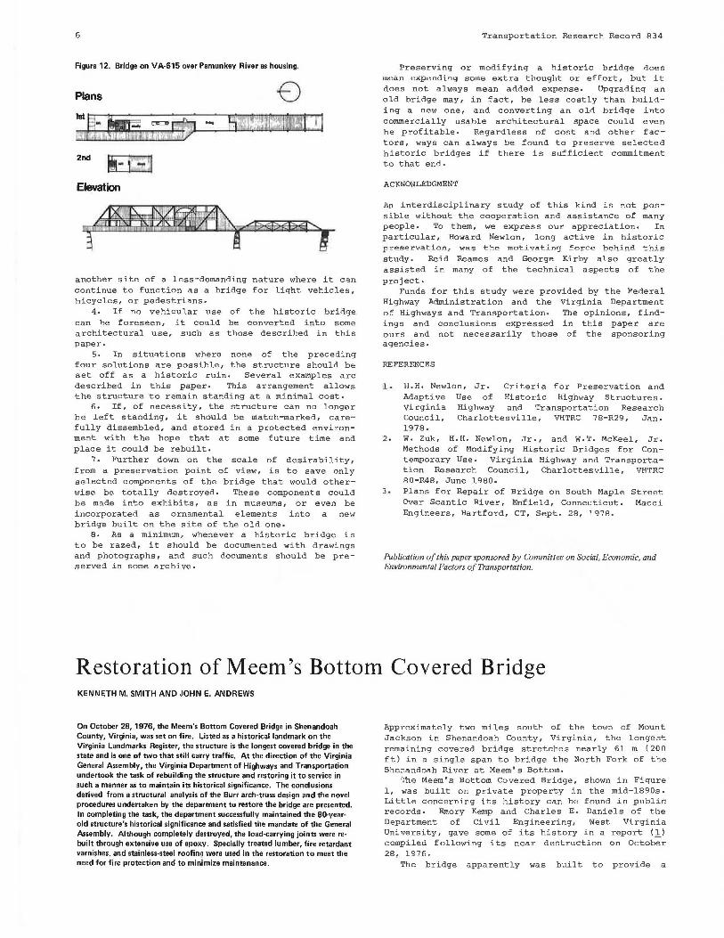
Figure 12. Bridge on VA·615 over Pamunkey River as housing.
Plans
2nd
Elevation
another site of a less-demanding nature where it can continue to function as a bridge for light vehicles, bicycles, or pedestrians.
4. If no vehicular use of the historic bridge can he foreseen, it could be converted into some architectural use, such as those described in this paper.
s. In situations where none of the preceding four solutions are possible, the structure shoulo be set off as a historic ruin. Several examples are described in this paper. This arrangement allows the structure to remain standing at a minimal cost.
6. If, of necessity, the structure can no longer be left standing, it should be match-marked, carefully dissembled, and stored in a protected environment with the hope that at some future time and place it could be rebuilt.
7. Further down on the scale of desirability, from a preservation point of view, is to save only selected components of the bridge that would otherwise be totally destroyed. These components could be made into exhibits, as in museums, or even be incorporated as ornamental elements into a new bridge built on the site of the old one.
9. As a minimum, whenever a historic bridge is to be razed, it should be documented with drawings and photographs, and such documents should be preserved in some archive.
Transportation Research Record 834
Preserving or modifying a historic bridge does rn.ean expending soute extra thought or effort, but it does not always mean added expense. Upgrading an old bridge may, in fact, be less costly than building a new one, and converting an old bridge into commercially usable architectural space could even be profitable. Regardless of cost and other factors, ways can always be found to preserve selected historic bridges if there is sufficient commitment to that end.
ACKNOWLEDGMENT
An interdisciplinary study of this kind is not possible without the cooperation and assistance of many people. To them, we express our appreciation. In particular, Howard Newlon, long active in historic preservation,. was the motivating force behind this study. Reid Reames and George Kirby also greatly assisted in many of the technical aspects of the project.
Funds for this study were provided by the Federal Highway Administration and the Virginia Department of Highways and Transportation. The opinions, findings and conclusions expressed in this paper are ours and not necessarily those of the sponsoring agencies.
REFERENCES
l • H.H. Newlon, Jr. Criteria for Preservation and Adaptive Use of Historic Highway Structures. Virginia Highway and Transportation Research Council, Charlottesville, VHTRC 78-R29, Jan. 1978.
2. W. Zuk, H.H. Newlon, Jr., and W.T. McKeel, Jr. Methods of Modifying Historic Bridges for Contemporary Use. Virginia Highway and Transportation Research Council, Charlottesville, VHTRC 80-R48, June 1980.
3. Plans for Repair of Bridge on South Maple Street Over Scantic River, Enfield, Connecticut. Macci Engineers, Hartford, CT, SP.pt. 2A, 1g1A.
Publication of this paper sponsored by Committee on Social, Economic, and Environmental Factors of Transportation.
Restoration of Meem's Bottom Covered Bridge KENNETH M. SMITH AND JOHN E. ANDREWS
On October 28, 1976, the Meem's Bottom Covered Bridge in Shenandoah County, Virginia, was set on fire. Listed as a historical landmark on the Virginia Landmarks Register, the structure is the longest covered bridge in the state and is one of two that still carry traffic. At the direction of the Virginia General Assembly, the Virginia Department of Highways and Transportation undertook the task of rebuilding the structure and restoring it to service in such a manner as to maintain its historical significance. The conclusions derived from a structural analysis of the Burr arch-truss design and the novel procedures undertaken by the department to restore the bridge are presented. In completing the task, the department successfully maintained the 80.yearold structure's historical significance and satisfied the mandate of the General Assembly. Although completely destroyed, the load-carrying joints were rebuilt through extensive use of epoxy. Specially treated lumber, fire retardant varnishes. and stainless-steel roofin~ were used in the restoration to meet the need for fire protection and to minimize maintenance.
Approximately two miles south of the town of Mount Jackson in Shenandoah County, Virginia, the longest remaining covered bridge stretches nearly 61 m ( 20 0 ft) in a single span to bridge the North Fork of the Shenandoah River at Meem's Bottom.
The Meem's Bottom Covered Bridge, shown in Figure 1, was built on private property in the mid-1890s. Little concerning its history can be found in public records. Emory Kemp and Charles E. Daniels of the Department of Civil Engineering, West Virginia University, gave some of its history in a report (.),_) compiled following its near destruction on October 28 , 1976.
The bridge apparently was built to provide a