Embed Size (px)
Citation preview

RESEARCH Open Access
Adaptive neighbor-based topology controlprotocol for wireless multi-hop networksZeeshan Hameed Mir1 and Young-Bae Ko2*
Abstract
Topology control protocols have been proposed to construct efficient network topologies with several designgoals, e.g., network-wide connectivity, minimal energy cost, symmetry, lower nodal degree, and therefore higherspatial reuse or lower interferences. Neighbor-based topology control protocols are simple and assume that eachnode in the network is connected to its k least-distant neighbors. There have been several empirical andtheoretical research efforts that recommend a network-wide optimal value of the local parameter k. However, sincemost of the design goals often run against each other the suggested lower and upper bounds on the values of kare not sufficient to provide a controllable trade-off among various design goals. In this article, an adaptiveneighbor-based topology control protocol is presented where the neighboring nodes collaborate and providefeedback on the network connectivity to decide on their respective transmission ranges. Since every nodeadaptively adjusts its number of neighbors, the parameter k acts as a performance knob to choose a set ofbackbone nodes and to form a hierarchical topology structure consisting of symmetric links. Through extensivesimulation-based study, it is shown that the value of k can be tuned to generate fully connected networktopologies while offering an efficient trade-off among various design goals.
Keywords: topology control, neighbor-based, wireless multi-hop networks
1. IntroductionTopology control [1,2] leads to a simpler network topol-ogy with several design goals such as network-wide con-nectivity, minimal energy cost, symmetry, lower nodaldegree, and therefore higher spatial reuse or lower inter-ferences. In neighbor-based [3,4] topology control proto-cols, each node connects to its k least-distant neighbors.The neighbor-based protocols are often characterized bytheir simplicity and the use of minimum amount ofinformation needed by nodes to construct the networktopology. However, finding an optimal value of k suchthat some or most of the design goals are achieved hasbeen a challenging task.The network topology induced by setting a lower
value of k is either not fully connected and/or consistsof asymmetric links. On the other hand, the recom-mended upper bound on the value of k causes signifi-cant redundancy in nodal degree which is a measure of
the spatial reuse and interference. There have been sev-eral research efforts both empirically and theoretically tofind an optimal, network-wide value of the local para-meter k. However, since most of the design goals suchas connectivity, energy cost, symmetry, and nodal degreeoften run against each other the suggested lower andupper bound on the values of k are not sufficient to pro-vide a controllable trade-off among various design goals.While the focus of most of the previous investigations
rested on finding the number of neighbors that arenecessary for connectivity [5,6] and on how differentnetwork models and design goals influence the value ofk [3,4], they miss the potential of collaboration amongneighboring nodes where nodes provide feedback on thenetwork connectivity to decide on their respective trans-mission ranges. Nodes start with connecting to theleast-distant neighbors, check for local network connec-tivity information and adjust the number of neighborsto achieve an efficient trade-off among various designgoals.This study describes an adaptive neighbor-based
topology control (ANTC) protocol that constructs fully
* Correspondence: [email protected] of Information and Computer Engineering, Ajou University, Suwon,Republic of KoreaFull list of author information is available at the end of the article
Mir and Ko EURASIP Journal on Wireless Communications and Networking 2012, 2012:97http://jwcn.eurasipjournals.com/content/2012/1/97
© 2012 Mir and Ko; licensee Springer. This is an Open Access article distributed under the terms of the Creative Commons AttributionLicense (http://creativecommons.org/licenses/by/2.0), which permits unrestricted use, distribution, and reproduction in any medium,provided the original work is properly cited.

connected network topologies while it addresses numberof design goals efficiently. The basic idea is to select asubset of nodes that serve as the network backbone andto form a hierarchical topology structure consisting ofsymmetric links. The process of backbone node selec-tion is carried out in a distributed manner withoutrequiring global network connectivity knowledge. Theproposed ANTC protocol runs in three phases. Firsteach node discovers its one-hop neighbors. Next thesink or base station node initiates the topology con-struction (TC) phase by broadcasting a control message.Among other attributes, the control message containsinformation on local neighborhood connectivity. Onreceiving the control message, each node checks for net-work connectivity requirements and adjusts its numberof neighbor accordingly. The control message is then re-broadcasted exactly once by means of controlled flood-ing. This process is realized by mean of node coloringalgorithm where initially all nodes are WHITE in color.During the TC phase nodes change their color accord-ing to the feedback information on network connectiv-ity. The backbone nodes are colored BLACK whereasthe other nodes are either RED or BLUE. Both RED andBLUE nodes are linked symmetrically with the BLACKnode, while BLUE nodes are also candidate BLACKnodes. In the last phase, topology maintenance is per-formed in order to avoid disconnected networks due toany control message loss or collision.The simulation results validate our claim that the pro-
posed ANTC protocol shows a versatile performance forthe given set of design goals. The following factorsmake our work extremely useful for wireless ad hoc andsensor networks.• A practical and distributed protocol that construct
fully connected network topologies consisting of sym-metric links. The local topology parameter k act as aperformance knob that offers an efficient trade-offamong several conflicting design goals.• A hierarchy of backbone nodes are selected using
the communication overhead of at most 3n messages,where n is the total number of nodes in the networks.Lower message complexity makes the ANTC protocolscalable and suitable for energy and resource constraintsensor networks.• The hierarchy of backbone nodes implicitly setups
the forwarding path towards the common sink or basestation node.• Through extensive simulation-based study the qual-
ity of the generated topology is evaluated against severalcriteria such as network-wide connectivity, minimalenergy cost, higher spatial reuse, or lower interferenceby means of lower nodal degree.The rest of this article is organized as follows. Section
2 gives a brief overview of the related work and expands
on the problem statement. Section 3 presents an ANTCprotocol in detail which is followed by the performanceevaluation which is given in Section 4. Finally Section 5concludes the article.
2. Related work and motivation2.1. Related work on topology controlIn this section, we will discuss a number of neighbor-based topology control protocols found in the literatureand comment on how they construct network topologywith the desired set of deigns goals.In k-Neighbor [3,4] and XTC [7] protocols, each node
creates an ordered neighbor list, which ranks all one-hop neighboring nodes with respect to their distance,energy, or link quality. Both protocols are simple toimplement, localized, and communication efficient. Thek-Neighbor protocol simply chooses the value of k to be6 and 9 to achieve week and strong requirements onconnectivity, respectively. However, the final topology isconstructed by keeping only symmetric links with fewerthan k least-distant neighbors. In XTC, each nodelocally traverses the neighbor list in non-decreasingorder of their ranks. At some arbitrary node u if a can-didate node v can be reached through an intermediateneighbor w with better rank (i.e., link quality), then thelink between node u and v is marked redundant and istherefore not included in the final topology.There is a class of neighbor-based topology control
protocols that tries to keep the number of neighborswithin a certain minimum and maximum thresholdvalues kmin and kmax. The example protocols includeLocal Information No Topology (LINT)/Local Informa-tion Link-state Topology (LILT) [8], MobileGRID [9],Novel Topology Control Protocol (NTC) [10], andCooperative Nearest Neighbor (CNN) [11]. Each proto-col consists of two phases which adaptively adjust thetransmission ranges by including or excludes links fromthe final topology. Both phases are responsible for main-taining the nodal degree within certain configurablebounds. Mainly the algorithms differ in actually whattriggers the range adjustment at each node. For exam-ple, in LILT, the absence/presence of routing updatesdetermines whether the node is disconnected or not.LINT, on the other hand, periodically checks for num-ber of active neighbors and tries to keep the neighborcount around a desired value. Likewise LINT, the Mobi-leGRID protocol, utilizes the nodal degree for maintain-ing a specific contention index. The nodal degree valueis preconfigured and depends on the node density, net-work area, and transmission range. NTC and CNN areespecially designed to mitigate the network partitioningproblem which usually arises when the wireless nodesoperate at lower values of k. For uniform node distribu-tion, the topology constructed by the local connections
Mir and Ko EURASIP Journal on Wireless Communications and Networking 2012, 2012:97http://jwcn.eurasipjournals.com/content/2012/1/97
Page 2 of 17

can perform well. However, with clustered node distri-bution the NTC and CNN algorithms may result intopartitioned network for the given lower bound of k.The quality of a generated topology can be measure
with respect to several design goals such as connectivity,energy cost, symmetry, spatial re-use and interference,etc. More recently, Banner and Orda [12] proposed atopology control protocol that caters for a wide array ofdesign goals. The authors argue that the previous workconcentrated more on finding nodes’ transmission rangeby keeping in mind the rarely occurring worst-case sce-narios. Most of the previous approaches towards topol-ogy control would certainly yield optimal performancefor only a small subset of the design goals which areoften conflicting in nature. Through both analytical andsimulation studies they demonstrate that their protocolis capable of achieving average performance for a varietyof topology related parameters simultaneously.
2.2. MotivationIn neighbor-based topology control protocols, the mainfocus is on finding a network-wide optimal value of thelocal parameter k that could result in an efficient topol-ogy, i.e., fully connected and energy minimal. To caterdifferent network models and design goals, the value fork is often too large to achieve several conflicting designgoals, simultaneously. Consider a 10-node networkgiven in Figure 1 where dashed lines represent theasymmetric links and the solid lines represent the sym-metric links. Here, node 1 is the sink node or base sta-tion to collect the data generated by all the other nodes.As illustrated in Figure 1d, it is not until k set to 4, thata fully connected network topology consisting of sym-metric links is obtained. However, to account for worst-case scenarios the network operates at even highervalues of k, i.e., 9 or (n - 1). Clearly, the larger values ofk result in significantly large number of redundant linksand thus higher interferences among the neighboringnodes. Moreover, larger transmission ranges result inhigher energy cost while having longer forward progress[10] and thus lower path length towards the final desti-nation. Conversely, the Minimum Spanning Tree (MST)[13] generates sparser network topology (given in Figure1f) which results in fewer links and lower energy con-sumption. However, the path length among source-des-tination pairs increases significantly.For the recommended value of k, all the nodes are
forced to have larger neighborhood because some of thenodes might have too few neighbors or asymmetriclinks. However, only a small subset of nodes is requiredto extend their number of neighbors provided that eachnode is aware of the local network connectivity for theselected value of k. For example in Figure 1c, each nodeestablishes links to their three least-distant neighbors
(i.e., k = 3). However, there are only two pairs of nodes(8, 9) and (4, 6) that are linked asymmetrically. Consid-ering distance as the metric to decide on which pair,nodes 4 and 6 may collaborate to increase their trans-mission range enough to have an efficient topology.Likewise in Figure 1b with k = 2 and in Figure 1a withk = 1 there are at least three and five pairs of nodes,respectively.Interestingly, as the k increases, so does the number of
symmetric links and as a result the number of nodepairs decreases. It is also noteworthy that how the selec-tion of node pairs could possibly effect the forward pro-gress and nodal degree at each node. For example inFigure 1b for node 9, selecting node 8 instead of node2, save half of the hop distance towards the sink. There-fore, the value of k certainly acts as a performance knobwhich can be tuned to achieve an efficient trade-offamong various design goals concurrently. Moreover,instead of following a network-wide value of the localparameter k, all the nodes locally adjust their number ofneighbors accordingly.
3. Adaptive neighbor-based topologycontrol (ANTC)Consider a wireless network comprising of n - 1 ordin-ary nodes and a single sink or base station node (thustotal n nodes). All the nodes are stationary and deployedrandomly throughout the two-dimensional space. It isassumed that all the nodes are equipped with homoge-neous, single RF radio with an omni-directional antennaand are capable of adjusting their RF output power atseveral discrete levels [14,15]. Furthermore, the underly-ing topology is fully connected at maximum transmis-sion range Txmax. The main objective of the ANTCprotocol is to provide a controllable and efficient trade-off among various design goals such as network-wideconnectivity, minimal energy cost, symmetry, and lowernodal degree for any given value of the local parameterk, with 0 <k ≤ n - 1. The proposed ANTC protocol con-sists of three phases.
3.1. Neighbor discovery phaseInitially, each node i announces its presence using MAClayer beaconing at Txmax. A simple yet practically reli-able one-hop broadcast mechanism [16] can be used toreduce the chances of a node remain undiscovered byits neighbors. The idea is to make sure that all thenodes receive the discovery message and construct acomplete neighbor list. Upon successful receiving theANNOUNCE message from node i, the neighboringnode j estimates its distance to node i. An all neighborlist N∗
j is maintained which consists of two attributes,a unique neighbor identity and their distance. The
Mir and Ko EURASIP Journal on Wireless Communications and Networking 2012, 2012:97http://jwcn.eurasipjournals.com/content/2012/1/97
Page 3 of 17

neighbor list is then stored in non-decreasing order ofthe distance. Algorithm 1 illustrates the above-men-tioned procedure.The higher cost of operating GPS-enabled nodes
makes this option of acquiring the distance informationnearly infeasible. Instead, techniques that utilize differ-ent physical measurements, e.g., Received SignalStrength Intensity (RSSI) [17] and Time of Arrival(ToA) [18] can be employed to estimate the distancebetween two nodes. The use of RSSI and ToA-basedmechanisms often raised criticism by the researchersdue to the distance measurement error which is usuallycaused by attenuation present in the atmosphere ornon-line of sight (i.e., the obstacles). However, in theperformance evaluation section it is shown that theANTC protocol achieves resilience to error in distanceestimation at much lower cost than the previous work.
Although this article utilizes the estimated distancebetween two nodes, other metrics such as link quality,residual energy can also be combined.
3.2. TC phaseANTC is essentially a node coloring algorithm, whichcreates a single topology structure consisting of backbonenodes. The number of backbone nodes and other topol-ogy-related properties are decided based on the inputparameter k. During the course of the TC phase, eachnode can have one of the four colors. Nodes modify theircolors in response to the reception (or overhearing) ofnetwork connectivity information within the TC mes-sages. As the TC phase proceeds, the nodes change theircolors according to the following definitions. For ease ofreference, Table 1 provides a list of parameters and algo-rithmic notations that are used throughout the article.
910
4
2
1
5
37
8
6
910
4
2
1
5
37
8
6
910
4
2
1
5
37
8
6
(a) k-Neighbor with k=1 (b) k-Neighbor with k=2 (c) k-Neighbor with k=3
910
4
2
1
5
37
8
6
109
4
2
1
5
37
8
6
910
4
2
1
5
37
8
6
(d) k-Neighbor with k=4 (e) k-Neighbor with k=9 (f) Minimum Spanning TreeFigure 1 Topology snapshot by applying k-Neighbor topology control protocol with k = 1, 2, 3, 4, and 9 for (a)-(e), respectively, and(f) MST. Symmetric links are represented by solid lines and asymmetric links are represented by dashed lines.
Mir and Ko EURASIP Journal on Wireless Communications and Networking 2012, 2012:97http://jwcn.eurasipjournals.com/content/2012/1/97
Page 4 of 17

• WHITE: A node in its initial state which has notreceived and thus acted upon the information withinthe TC message.• BLACK: The backbone nodes are colored BLACK,which guarantees symmetric link towards the com-mon sink or base station node.• RED: A RED colored node is associated k-symme-trically with a BLACK node. If a WHITE node jreceives the TC message from node i, i.e. ( j ∈ NK
i
and i ∈ Nkj ), it turns into RED color. In other
words, nodes i j have symmetric links for the givenvalue of k.• BLUE: A BLUE node is associated k-asymmetri-cally with a BLUE or BLACK node. If a WHITEnode j receives the TC message from node i, i.e.
( j /∈ Nki and i ∈ Nk
j ), it turns into BLUE color. In
other words, node j has an asymmetric link withnode i’ for the given value of k.
The sink or base station node initiates the TC phaseby broadcasting the TC message at Txmax. The ANTCprotocol exploits the broadcast nature of the wirelesscommunication channel. Each node selects an appropri-ate set of neighbors by overhearing the ongoing commu-nication among its neighboring nodes. The process ofselecting next node to disseminate its TC message is bita like peeling the onion layers inside-out. Nodes that arecloser to the initiator are given higher priority as com-pare to the farther ones. The TC message is alsorequired to maintain proper value of hop distance valuetowards the initiator. As the TC phase proceeds, the TCmessage disseminates in a controlled manner such thateach node relays the TC message only once. Each node
i maintains and updates the following attributes of theTC message.
• i.Identity_: Unique identity of node i.• i.Backbone_: Identity of a neighboring node whichguarantees symmetric link towards the common sinkor base station node.• i.HopCount_: Total distance in terms of number ofhops from sink or base station to the current node.• i.Color_: Color of node i.
• k-Neighbor list (Nki ): A list of k least-distant
neighbors of node i.
Following are the main highlights of the ANTC algo-rithm.
• Algorithm 2 illustrates the TC message attributeinitialization at sink node i. The sink node turnsBLUE, before it broadcast the TC message into itsimmediate one-hop neighborhood.• Lines 10-33 describe the steps taken by node jupon receiving the TC message from node i. Thereare three courses of actions j may take depending onits current status.
○ Form lines 10-18, node j verifies whether it hasa k-symmetric or k-asymmetric link with node i.If i and j are linked k-symmetrically, the receiverWHITE node becomes RED. In case of k-asym-metric link, the receiver WHITE node turnsBLUE otherwise the color remains unchanged.This part of the pseudo-code also performs twoimportant steps, i.e., first a soft state is main-tained for each sender node and secondly asym-metric links are eliminated during this process.
Table 1 Algorithmic notation and data structures
WHITE color Ordinary node
RED color k-symmetric neighbor
BLUE color k-asymmetric neighbor
BLACK color Backbone node
n Total number of nodes in the network
Txmax Maximum transmission range
N∗i Set of all one-hop neighbors of node i
Nki Set of k least-distant neighbors of node i
Txki Transmission range of node i required to reach the farthest neighbor in Nk
id(i, j) Estimated distance between nodes i and j
Tmax Maximum delay a node must wait, before initiating the next step
Td, fwd Forwarding delay for TC message
Tinterval Forwarding interval for TC message
i.msgCache_ { nb.Identity_; nb.Distance_; nb.Color_;nb.Backbone_; nb.HopCount_; } entry;
Mir and Ko EURASIP Journal on Wireless Communications and Networking 2012, 2012:97http://jwcn.eurasipjournals.com/content/2012/1/97
Page 5 of 17

○ Lines 19-26 are followed if j has not yet sentits TC message. Before a node broadcasts its TCmessage further into the network, it has todecide on two aspects, i.e., (1) the backbonenode and (2) the TC message forwardingsequence. Later in this section, more details willbe provided.○ Last, lines 27-32 are only executed, if j over-hears the TC message from one of its neighbor-ing node which has selected j as the backbonenode. If the sender’s information is not already
in the Nkj , it is then included and the transmis-
sion range is extended to reach the most distantneighbor in the k-Neighbor list.
• The topology maintenance phase, ensures that TCphase remain resilient to TC message lose.
To make a single connected topology structure con-sisting of symmetric links towards a common sink, eachnode must select a backbone node. The intuition behindselecting a BLUE node as the backbone is very simple.First, for the given value of k the BLUE nodes are farth-est from the sender node, which are also linked k-asym-metrically with another potential backbone node.Second, the fact that BLUE node would operate at largertransmission ranges therefore they give better perfor-mance trade-off between energy costs and hop dis-tances. The use of distance information further helps inchoosing better candidate among several BLUE nodes.Finally, in scenarios (especially for higher values of k)where there exist fewer BLUE nodes, any least-distantneighbor which is minimal hops away from sink node isselected. In Algorithm 3, lines 1 through 11 describe thebackbone node selection procedure. Lines 12-15 set therequired TC message attributes before they are furtherbroadcasted by the receiver node j. For example, the j.Backbone_ attribute holds the selected backbone’ iden-tity, the hop count attribute gets an increment, andfinally if nodes current color is WHITE, it changes intoBLUE. Lines 16-19 simply update the k-Neighbor listand set the transmission range that is required to reach
the farthest neighbor in Nkj .
In ANTC, each node decides backbone based on theneighbor’s color, estimated distance, and hop distancetowards the sink node. While the TC phase is in pro-gress the exact path length from the sink to the currentnode cannot be known in advance. Therefore, the nodecolor and the hop distance information are includedwithin the TC message. The value in the hop countattribute is incremented each time a node forwards theTC message further into the network. To calculate cor-rect accumulated value of the hop count, the forwardingsequence of TC message requires special consideration.
A distance-based message dissemination approach isutilized which introduces forwarding delay for eachnode based on their distance from the previous node.The delay heuristic is implemented with the help of asimple timer (see Lines 19-26, Algorithm 2) and itworks in two ways. First, the TC message is flooded in acontrolled manner, i.e., it ensures that each node disse-minates the TC message only once. Up on receiving thefirst TC message each node set the timer value based onthe parameter Td,fwd, given at line 20. The timer value isset proportional to the distance between the receivingnode and the previous node. Once set, the timer valuecannot be re-initiated by overhearing of any subsequentTC message. Second, the coloring of the nodes and theincrement in hop count value require a proper forward-ing sequence, i.e., a node that is at nth hops distancefrom the previous node forwards the TC message beforea node n + 1th hops away. Thus, the cumulative effectis to give higher priority to the nodes that are closer tothe pervious node.In practice, the actual transmission time of a TC mes-
sage is determined by the combination of the timervalue and the time required by functions performed bya particular medium access control protocols. Forinstance, in contention-based MAC protocols, randomback-off is performed for each message to make sure itssuccessful reception at the receiver. Consider an exam-ple where the forwarding interval (Tinterval) is 1 timeunit and the nodes’ Txmax is set to 1.5 units. Let, nodesi and j are at the same distance from the previous nodeS (1 distance unit), they decide to forward the TC mes-sage at time 0.67 (= 1 × 1/1.5). However, in order tobreak the tie between nodes i and j, the actual sendingcan be differentiated by the CSMA/CA mechanism atthe MAC layer. More importantly, nodes are notrequired any form of strict time synchronization for dis-tance-based forwarding to work properly. Distance-based forwarding can lead to slightly longer time. How-ever, since the TC phase last for very small fraction ofoverall network operational time, therefore its effect canbe consider negligible on the network performance.To exemplify the proposed heuristics, a simple topol-
ogy given in Figure 2 is considered. In current example,k is set to 2 and the neighbor list is shown in parenth-esis besides each node i. The sink node S initiates theTC phase by first turning its color to BLUE and thenbroadcasting a TC message at Txmax (represented by thedotted lines). The contents of the TC messages aregiven within each figure. On reception, all the neighbor-ing nodes calculate the timer value to send their respec-tive TC messages. Based on the estimated distance fromthe sender node, each node will calculate its forwardingsequence. In this example, the forwarding sequence isrepresented by the alphabetical order given as node IDs.
Mir and Ko EURASIP Journal on Wireless Communications and Networking 2012, 2012:97http://jwcn.eurasipjournals.com/content/2012/1/97
Page 6 of 17

Figure 2a shows the coloring of the nodes after the TCmessage is received by the neighbors from the sink nodeS. Since nodes A and B have 2-symmetric links with S,they turn RED. Similarly, nodes C, D, and E will turnBLUE because of their 2-asymmetric links. Whereasnode F’s color remains WHITE, because node F isneither linked k-symmetrically nor k-asymmetricallywith node S.In order to construct a fully connected backbone, each
node has to be linked symmetrically with a special back-bone node so that it guarantees a symmetric linktowards the sink. For RED nodes, the selection of back-bone node is simple, since they already have symmetriclink with a BLUE node. Figure 2b illustrates the processwhere node A selects S and send the TC message. Thedecision regarding backbone selection is conveyed to theother nodes while they overhear the ongoing communi-cation. Once node S finds out that node A has selected
it as the backbone node it changes its color to BLACK.In Figure 2c, node B repeats the same procedure.For the given value of k, a node might have no k-sym-
metric neighbors thus resulting in either asymmetriclinks or network partitioning. Nodes C, D, and E repre-sent the first case where they are associated k-asymme-trically with node S. These nodes select node S as thebackbone node (the least-distant BLUE node) and con-vey this decision in their respective TC messages. Onoverhearing the TC messages, node S extends its neigh-bor list and sets its transmission range to the level thatis required to reach the farthest neighbor in the neigh-bor list. The selected backbone node turns BLACK (ifnot already BLACK color). In Figure 2d, nodes C and Dperform the above procedure with node S, followed bynode E in Figure 2e. The nodes retain links with their k-symmetric neighbors. Node F represents the second casewhere the network is partitioned between nodes F and
(A,S)
(C,S)(S,D)
(B,S)
(S,F)
(X,Y)
SD B A C
E
F
TCS={S,S,0,BLUE,(A, B)}
(A,B) (A,B) (A,S)
(C,S)(S,D)
(B,S)
(S,F)
(X,Y)
D B C
E
F
TCA={A,S,1,RED,(C,S)}
SA
(A,B) (A,S)
(C,S)(S,D)
(B,S)
(S,F)
(X,Y)
D B C
E
F
TCB={B,S,1,RED,(S,D)}
SA
(a) TC message by node S. (b) TC message by node A. (c) TC message by node B.
(A,B,C) (A,S)
(C,S)(S,D)
(B,S)
(S,F)
(X,Y)
SD B A C
E
F
TCC={C,S,1,BLUE,(A,S)}
(C,S)(S,D)
(S,F)
(X,Y)
SDB C
E
F
A
TCE={E,S,1,BLUE,(S,F)}
(B,S) (A,B,C,D,E) (A,S) (A,S)
(C,S)(S,D)
(S,F)
(X,Y,E)
SDB A C
E
TCF={F,E,2,BLUE,(X,Y,E)}
F
(A,B,C,D,E)(B,S)
(d) TC message by node C. (e) TC message by node E. (f) TC message by node F.Figure 2 Diffusion process of TCi message for k = 2; with four types of information, of node i i.e., {i.Backbone_, i.HopCount_, i.Color_,and N2
i } at Txmax. (a) TC message by node S. (b) TC message by node A. (c) TC message by node B. (d) TC message by node C. (e) TCmessage by node E. (f) TC message by node F.
Mir and Ko EURASIP Journal on Wireless Communications and Networking 2012, 2012:97http://jwcn.eurasipjournals.com/content/2012/1/97
Page 7 of 17

E. In Figure 2f, the WHITE node F selects node E as thebackbone node. Node F is associated k-asymmetricallywith two other neighbors X and Y (not shown in the fig-ure). Before the TC message is sent further into the net-work, node F turns BLUE and increments the hopcount value by 1. In scenarios where there exists noBLUE node, any least-distant node which is minimumhops away from the sink is selected. The hop countvalue is incremented as the TC message is disseminatedacross the network. The forwarding sequence of the TCmessage ensures that path length value is incrementedproperly.The proposed ANTC protocol results in a single tree-
like structure, where RED and BLUE nodes are associatedsymmetrically with the set of BLACK nodes. The BLACKnodes are linked directly with relatively larger transmis-sion ranges, thus forming a connected backbone. Inorder to control the number of backbone nodes and theassociated links, the value of k is utilized as a perfor-mance knob. The performance evaluation section showsthat the value of k provides an efficient trade-off amongvarious design goals. The other advantage of topologyconstructing phase is that it also constructs an implicitdata forwarding hierarchy consisting of backbone nodestowards the sink or base station node.
3.3. Topology maintenance phaseThis section describes a scenario where the TC messageis lost either due to collision or unsuccessfully receptionat the receiver. The lost of TC message is significant,because it contains information regarding the backbonenode that a potential BLACK node could not receive.The given scenario often leads to asymmetric linkswhere the selected backbone node remains unable toextend its transmission range up to the requesting node.Each node i checks whether it has received/overheardthe TC message from all its one-hop neighbors. If not,then it broadcasts the Topology Repair Request(TRREQ) message at Txmax. On reception, only thosenodes j would respond with the Topology Repair Reply(TRREP) message that has a k-asymmetric links with thenode i. Finally, on receiving the TRREP message node iextend its transmission range to include node j. Algo-rithm 4 describes the above procedure.
4. Performance evaluations4.1. Simulation environmentTo evaluate ANTC and other neighbor-based topologycontrol protocols, extensive simulations are performedusing NS-2 [19] simulator. In the simulation study, thenetwork size n is varied from 100 to 250 in incrementsof 50 and 500 nodes. The network sizes representsparse, moderate, and densely populated networks. Allthe nodes are placed randomly over a 1000 × 1000 m2
area with the sink or base station node positioned at thecenter. The maximum transmission range Txmax is setto 250 m. In our simulations, Tinterval is set to 1 s andTxmax is set to an arbitrary constant large enough toavoid interruption with the ongoing TC phase.For a comparative study, following neighbor-based
topology control protocols are considered where all theresultant topology instances are fully connected andconsisting of symmetric links.
• MST: Most of the topology control protocols idea-lize topologies generated by the MST algorithms.However, the requirements of global information atsome arbitrary common node make the MST algo-rithm less feasible to implement especially for large-scale sensor networks.• CNN with k set to 5: In CNN, all the nodes areconnected to their k = kmin = kmax least-distantneighbors. The CNN protocol is evaluated with k =5 (given as k-CNN).• k-Neighbor with k set to 9: The results obtain fork-Neighbor protocol suggest that to achieve strongrequirements on connectivity the value of k must beset to 9. The final topology is referred as k-Neighbor.
Following three metrics are used for performance eva-luations. The final values are obtained by averaging 100different simulation runs over 100 different randomlygenerated network topologies. All the measurements areaveraged over the network sizes.
• Total energy cost is defined as∑n
i=0(Txk
i )α, where
Txki represents the transmission range assigned to
reach the kth neighbor in the neighbor list at theend of individual topology control protocol and a isthe path loss constant typically with a value between2 and 6 [20].• Nodal degree is defined as the number of directneighbors. We consider both logical and physicalnodal degrees, where later is consider as a bettermeasure of expected contention.• Path length is defined as the number of hopstowards the common sink or base station node. Ashortest path algorithm is executed over the topol-ogy controlled network to measure path lengthbetween a node and the sink.
4.2. Simulation resultsFigure 3 illustrates the topology snapshots obtained byseveral topology control protocols. In k-Neighbor, thesample topologies are generated for k = 6 and 9, inCNN the value for k is set to 5 and finally the ANTC
Mir and Ko EURASIP Journal on Wireless Communications and Networking 2012, 2012:97http://jwcn.eurasipjournals.com/content/2012/1/97
Page 8 of 17

protocol is executed with k = 1, 2, 3, and 4. The net-work consists of 200 nodes. The topology generated bythe MST algorithm is the sparsest. For the neighbor-based protocols, the parameter value k determines thetopology resolution and other topological properties.In ANTC as the value of k increases, a denser
communication graph starts to appear. Intuitively, k actsas a performance knob which can be used to tune var-ious design goals such as energy cost, nodal degree, andpath length. For any given value of local parameter k,the proposed ANTC protocol constructs fully connectednetwork topologies consisting of symmetric links.
(a) Topology snapshot of MST algorithm. (b) Topology snapshot of 5-CNN protocol.
(c) Topology snapshot of 6-Neighbor protocol. (d) Topology snapshot of 9-Neighbor protocol.
(e) Topology snapshot of ANTC protocol with k=1. (f) Topology snapshot of ANTC protocol with k=2.
(g) Topology snapshot of ANTC protocol with k=3. (h) Topology snapshot of ANTC protocol with k=4.
Figure 3 Sample topology snapshot with 200 nodes: (a) Topology snapshot of MST algorithm, (b) k-CNN with k = 5, (c), (d) k-Neighbor with k = 6 and 9, (e)-(h) ANTC protocol with k = 1, 2, 3, and 4. Solid black lines represent backbone links.
Mir and Ko EURASIP Journal on Wireless Communications and Networking 2012, 2012:97http://jwcn.eurasipjournals.com/content/2012/1/97
Page 9 of 17
4.2.1. Performance comparison with various network size nFigure 4a reports on the energy cost for all the proto-cols. Since the energy cost measurements are averagedover network sizes, the per node energy cost decreasesas the network size increases for any given value of k.MST generated topologies are optimal in terms ofenergy cost. For the lowest value of k = 1, ANTC per-formed comparable to that of MST. The cost of main-taining a fully connected topology is highest for the 9-Neighbor protocol. Figure 4b shows the energy cost nor-malized with respect to MST. Overall the energy costincreases with the increase in the value of k. For theintermediate value of k the ANTC performance liesright between the two extremes of MST and 9-Neigh-bor. Compared to the 9-Neighbor protocol when n =100, ANTC with k = 1, 2, 3, and 4 provides an improve-ment of 102, 73, 43, and 30%, respectively. For all thenetwork sizes, ANTC with k = 4 performed reasonablybetter than the 5-CNN. Figure 4c plots the trends for allthe other protocols with path loss constant value set to2, i.e., a = 2.Figure 5a,b shows the average logical and physical
nodal degrees for all the protocols. For any given net-work size, the MST and ANTC with k = 1 performedidentically. The logical and physical nodal degreesincrease consistently for all the value of k. Generally, asthe k and n pair grows the network topology becomesincreasingly denser. Since logical nodal degree is consid-ered as the lower bound to the physical degree, the phy-sical degree is always higher than the logical degree.The 9-Neighbor protocol yields almost three timeshigher nodal degree as compared to ANTC protocolwith k = 1. Whereas the logical and physical nodaldegrees of 5-CNN protocol are nearly twice of theANTC protocol with k = 1. In ANTC, only the nodeswith asymmetric links tend to extend their transmissionranges to make a symmetric links with BLUE node,whereas the RED nodes are already associated with theleast-distant backbone nodes resulting in lower averagelogical and physical degree.Figure 6 shows average path length for the MST, k-
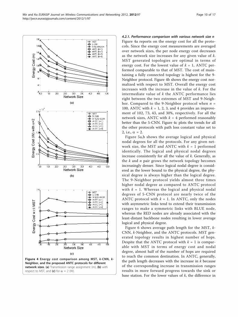
CNN, k-Neighbor, and the ANTC protocols. MST gen-erated topology results in highest number of hops.Despite that the ANTC protocol with k = 1 is compar-able with MST in terms of energy cost and nodaldegree, almost half of the number of hops are requiredto reach the common destination. In ANTC, generally,the path length decreases with the increase in k becauseof the corresponding increase in transmission rangesresults in more forward progress towards the sink orbase station. For the lower values of k, the difference in
(a)
(b)
(c)
Figure 4 Energy cost comparison among MST, k-CNN, k-Neighbor, and the proposed ANTC protocols for differentnetwork sizes. (a) Transmission range assignment (m), (b) withrespect to MST, and (c) for a = 2 (W).
Mir and Ko EURASIP Journal on Wireless Communications and Networking 2012, 2012:97http://jwcn.eurasipjournals.com/content/2012/1/97
Page 10 of 17

(a)
(b) Figure 5 Nodal degree comparison among MST, k-CNN, k-Neighbor, and the proposed ANTC protocols for different network sizes. (a)Logical, and (b) physical nodal degrees.
Mir and Ko EURASIP Journal on Wireless Communications and Networking 2012, 2012:97http://jwcn.eurasipjournals.com/content/2012/1/97
Page 11 of 17
path length is considerable. For example, for the firstfour values of k the percent decrement in hop counts iswithin the range of 6 to 20%. For most of the networksizes, the 9-Neighbor protocol performed better, how-ever at the expense of higher energy cost and nodaldegree. The performance of 5-CNN and the ANTC pro-tocol with k = 4 is comparable. The main reason beingthat in ANTC, a node only selects a backbone node thatis closer in terms of hop count and distance towards thecommon sink.These results demonstrate that the proposed ANTC
protocol achieves an efficient trade-off among variousdesign goals. The value of k acts as a performance knobwhich can be tuned to construct network topologieswith variety of different topological properties. Forexample, ANTC performed comparable with the optimalMST topologies in term of energy efficient and nodaldegree while maintaining shorter path lengths.4.2.2. Impact of k and n pair with respect to node colorTo further study the energy cost distribution, a closerlook on nodes with respect to their color is presented.Figure 7a,c,e shows that generally the BLACK nodesoperate at higher transmission range as compared to theRED and BLUE nodes for the given values of k and npair. This is due to the fact that the backbone nodeshave to extend their transmissions ranges beyond thecurrent value of k to construct a fully connected net-work topology. However, despite this, the BLACK nodesoperate at as high as 70% of Txmax for the sparsely node
deployment (Figure 7a). The energy cost of backbonenode decreases to 45 and 35% of Txmax as the networksize grows from moderate (Figure 7c) to highly densenetwork (Figure 7e), respectively. The energy cost ofRED nodes varies between 10 and 50% of Txmax
depending on the values of k and n pair. An increase ink results in corresponding increase in transmissionrange, therefore more distant nodes become k-sym-metric to the sender node. Whereas most BLUE nodeshave an average transmission range of 30% of Txmax.Since BLUE nodes are k-asymmetric nodes, thereforethey have to extend their range to create symmetriclinks.Since, the BLACK nodes dominate the energy cost, it
is therefore desirable to minimize the number ofBLACK nodes in the network. Interestingly, as given inFigure 7b,d,f, the number of BLACK nodes decreases asthe value of k increases for all network sizes. Thus,allowing less number of nodes to extend their transmis-sion ranges. The number of RED nodes on the otherhand increases. This is mainly because at higher valuesof k, the nodes tend to operate at higher transmissionrange, thus leading to more neighbors nodes to turnRED, i.e., k-symmetric nodes. Finally, the numbers ofBLUE nodes are nearly 10% of the network size n,which gradually decreases as the value of k increases.4.2.3 Impact of distance measurement error (DME)It is typically assumed that the distance estimations areerror free which is far less realistic than the actual
Figure 6 Path length comparison among MST, k-CNN, k-Neighbor, and the proposed ANTC protocols for different network sizes.
Mir and Ko EURASIP Journal on Wireless Communications and Networking 2012, 2012:97http://jwcn.eurasipjournals.com/content/2012/1/97
Page 12 of 17

situation. Specially, the assumption that the distance canbe estimated by mean of measuring certain physicalphenomena (i.e., RSSI and ToA), requires extra consid-erations. In k-Neighbor TC protocol, the recommendedvalue of k in presence of distance measurement error iseven higher than the actual value needed to achieve the
strong connectivity requirement for variety of networksizes. For network sizes n Î [100, 500], the preferredvalue of k is found to be 9 and 10, for ToA and RSSIerrors, respectively [3]. Resilience to the error in dis-tance measurement is achieved by simply connecting tothe even farther neighbor in the neighbor list.
(a) (b)
(c) (d)
(e) (f)
Figure 7 (a, c, and e) Percentage of Txmax assigned to and (b, d, and f) number of BLACK, RED, and BLUE nodes for different values ofnetwork size n and k pair.
Mir and Ko EURASIP Journal on Wireless Communications and Networking 2012, 2012:97http://jwcn.eurasipjournals.com/content/2012/1/97
Page 13 of 17
To show the impact of DME on proposed ANTC pro-tocol performance, the error model given in [3,21] isused with two different settings of the parameter values.The distance measurement between two nodes i and j is
given by d̂(i,j) = d(i,j) + RSSIe , where d̂(i,j) and d(i,j) are
defined as the measured and correct distances, respec-tively. The factor RSSIe is the ranging error (also DME
or RSSI error) is given asd(i,j)(1 − 10
Xσ
10α ), where Xs
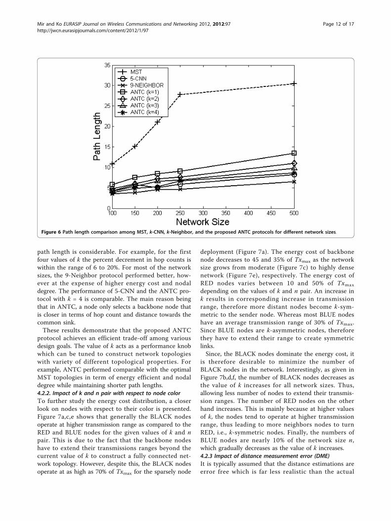
is a zero-mean Gaussian random variable with standarddeviation s and a is the path loss constant. For CASE-I,the parameter values are s = 1 and a = 4 and forCASE-II we set s = 0.84 and a = 2 in the RSSI errorequation (Equation 5 in [21]). CASE-I and CASE-IIyield almost 70% of the distance estimations errorswithin 6 and 10% of the correct distances, respectively.Figure 8 shows one of the instances for an empirical dis-tribution of distance measurement or RSSI error, (a)CASE-I and (b) CASE-II.A transmission range shorter than the actual would
certainly results in asymmetric links or network to parti-tion. Like k-Neighbor protocol, ANTC also let all thenodes extend their transmission ranges up to the fartherneighbor in the neighbor list. However, unlike the k-Neighbor protocol, where all nodes follow a network-wide value of the local parameter k, in ANTC nodesoperate at different number of least-distant neighborsaccording to their color for the given value of k. Eachnode i maintains an all neighbor ordered list N∗
i withrespect to the distance. The farthest node in the k-
Neighbor list Nki is located at some kth entry in the list
N∗i , which may not be the actual kth neighbor in N̂∗
i
list. The list N̂∗i holds faulty distance measurements,
obtained by applying the above-mentioned error modelduring the post-processing phase. To accommodateerror in distance estimation, each node adjusts its trans-
mission range to reach the k̂th = k + ηth neighbor in
N̂∗i , where h is a small positive integer constant set
according to the desired application requirements. Thevalue of h is increased until the specified requirementon the connectivity is achieved i.e., more than 95% ofthe nodes are connected in a single structure consistingof symmetric links.As suggested in [3], since the neighbor-based proto-
cols work on the notion of “nearest” neighbors and thefact that error cause by ToA are positive, we have notincluded results for ToA errors. The simulation resultsgiven in Table 2 are obtained for the network size of200 nodes with Txmax set to 250 m. For both CASE Iand CASE II, the preferred value of k̂th depends on theparameter k. For the lower value of k, the h is higherbecause the nodes tend to operate at lower transmissionranges and thus have fewer links. Consequently a discre-pancy in distance estimates more often results in parti-tioned network topology. In ANTC, on the average anincrement of 2 (i.e., k̂th = 5) and 3 (i.e., k̂th = 6) isrecommended, for CASE-I and CASE-II, respectively.Despite this, the final value of k̂th is considerably lowerthan the preferred value given in k-Neighbor protocol (i.e., k̂th = 10).It is noteworthy that as the value of k increases, the
network finds sufficient redundant links to maintain theprescribed requirements on the connectivity. Complying
(a) (b)
Figure 8 A representative instance for an empirical distribution of the DME or RSSI error for network size = 200 nodes. (a) CASE-I and(b) CASE-II.
Mir and Ko EURASIP Journal on Wireless Communications and Networking 2012, 2012:97http://jwcn.eurasipjournals.com/content/2012/1/97
Page 14 of 17

with the results obtained for the k-Neighbor protocol,our protocol also requires no further stretch in trans-mission range for higher value of k. Since, the solutionfor distance measurement error take into account thefarthest neighbor in the list, the backbone nodes andtheir associated nodes relationship remains intact. Onceagain the proposed ANTC protocol exhibits better per-formance to accommodate distance measurement errorat comparatively much smaller cost.
5. ConclusionTopology control protocols have been utilized in wire-less multi-hop networks to achieve variety of differentdesign goals. In this article, an ANTC protocol is pre-sented, aimed at constructing efficient network topolo-gies. The proposed ANTC protocol exploits thepotential of collaboration among neighboring nodeswhere nodes provide feedback on the network connec-tivity information to decide on their respective transmis-sion ranges. Based on the local connectivity informationeach node selects a backbone node that guarantees hier-archical topology structure consisting of symmetriclinks. The process of backbone node selection is carriedout in a distributed manner without requiring globalnetwork connectivity knowledge. To evaluate the perfor-mance of ANTC protocol against other protocols, wehave performed extensive simulation based study. Theresults demonstrate that ANTC achieves an efficienttrade-off among various design goals. The value of kacts as a performance knob which can be tuned to con-struct network topologies with up to 100% and threefoldimprovements in terms of energy cost and average nodaldegrees, respectively, while maintaining shorter pathlengths.
Algorithm 1: Neighbor discovery phase/*All n nodes exchange the ANNOUNCE messages*/Fornode j receives ANNOUNCE message from node i:/*Node j upon receiving an ANNOUNCE message
from node i stores one-hop neighbor identity and esti-mated distance in neighbor list N∗
j */
receiveANNOUNCE (i.Identity_) {1. N∗
j .insert (i.Identity_, d(I,j));
/*Sort neighbor list, in non-decreasing (ASCENDING)order of distance*/2. N∗
j .sort (N∗j .Distance_, ASC);
3. }
Algorithm 2: TC phaseFor the sink node i:/*Initialize*/1. Set: i.Identity_ = Sink;2. Set: i.Color_ = BLUE;3. Set: i.Backbone_ = Sink;4. Set: i.HopCount_ = 1;5. Set: i.isBroadcast_ = 0;/*Broadcast the TC message at Txmax*/6. Call: sendTC (i.Identity_, i.Color_, i.Backbone_, i.
HopCount_,Nki );
7. Set: i.isBroadcast_ = 1;8. Wait: Tmax units;9. Goto: Topology maintenance phase;For the other
node j:/*Upon receiving the TC message*/10 receiveTC(i.Identity_, i.Color_, i.Backbone_, i.Hop-
Count_, Nki ) {
/*Add TC message attribute into the msgCache_ datastructure*/11. j.msgCache_.insert (i.Identity_, d(i,j), i.Color_, i.
Backbone_, i.HopCount_);
12. if ( j ∈ NKi and i ∈ Nk
j ) {
13. if (j.Color_ == WHITE)14. Set: j.Color_ = RED; }
15. elseif ( j /∈ Nki and i ∈ Nk
j ) {
16. Nkj .erase (i.Identity_);
17. if (j.Color_ == WHITE)18. Set: j.Color_ = BLUE; }19. if (j.isBroadcast_ == 0) {20. Set: Td,fwd = Tinterval × d(i, j)/Txmax units;21. Initiate: diffusionTimer(Td, fwd) ;22. On expire:23. Call: findBackbone();24. Call: sendTC (j.Identity_, j.Color_, j.Backbone_, j.
HopCount_,Nkj );
25. Set: j.isBroadcast_ = 1;26. }27. if (i.Backbone_ = = j.Identity_) {28. Set: j.Color_ = BLACK;
29. if ( i /∈ Nkj )
30. Nkj .insert (i.Identity_, d(i, j));
31. Set: Txkj = max(Nk
j (1).Distance : Nkj (Nk
j .size()).Distance );
32. }33. }
Table 2 The value of k̂th for CASE-I and CASE-II withRSSI error
k kth without DME (i.e., no error) k̂th CASE-I h k̂th CASE-II h
1 3.28 5.28 2 6.28 3
2 4.34 6.34 2 6.34 2
3 5.67 6.67 1 6.87 1
4 7.84 8.62 1 8.79 1
Mir and Ko EURASIP Journal on Wireless Communications and Networking 2012, 2012:97http://jwcn.eurasipjournals.com/content/2012/1/97
Page 15 of 17

Algorithm 3: Procedure for finding thebackbone nodefindBackbone() {/*Initialize*/1. entry.Distance_ = 250; entry.HopCount_= 255;2. for (k Î j.msgCache_) {/* Find the least-distant neighbor with color = BLUE
*/3. if (k.Distance_ <entry.Distance_) and (k.Color_ ==
BLUE))4. Set: entry = k;5. }6. if (entry == NULL) {7. for (l Î j.msgCache_) {/* Find the least distant neighbor with least hops
towards the sink */8. if (l.Distance_ <entry.Distance_) and (l.HopCount_
≤ entry.HopCount_))9. Set: entry = l;10. }11. }12. Set: j.Backbone_ = entry.Identity_;13. if (j.Backbone_ ≠ Sink) Set: j.HopCount_ = entry.
HopCount_ + 1;14. if (j.Color_ == WHITE) Set: j.Color_ = BLUE;15. if (entry.Color_ == BLACK) Set: j.Color_ = RED;
16. if (entry.Identity_ ∉ Nkj )
17. Nkj .insert (entry.Identity_, d(entry.identity_,j));
18. Set: Txkj = max(Nk
j (1).Distance : Nkj (Nk
j .size()).Distance );
19. }
Algorithm 4: Topology maintenance phaseFornode i sends Topology Repair Request (TRREQ)message:1. if (i.msgCache_.size() <N∗
i .size())
2. Call: sendTRREQ(Nki );For the other node j sends
Topology Repair Reply (TRREP) message:/*Upon receiving the TRREQ message*/
3. receiveTRREQ(Nki ) {
4. if ( j /∈ Nki and i ∈ Nk
j )
5. Call: sendTRREP(j.Identity_);6. }For node i receives TRREP message from node j:7. receiveTRREP (j.Identity_) {
8. if ( j /∈ Nki )
9. Nki .insert (j.Identity_, d(i, j));
10. Set: Txki = max(Nk
i (1).Distance : Nki (Nk
i .size()).Distance );
11. }
AcknowledgementsThis research was supported by the MKE(The Ministry of KnowledgeEconomy), Korea, under the ITRC(Information Technology Research Center)support program supervised by the NIPA(National IT Industry PromotionAgency” (NIPA-2012-(C1090-1221-0011)).
Competing interestsThe authors declare that they have no competing interests.
Author details1RFID/USN Research Division, Electronics and Telecommunications ResearchInstitute (ETRI), Daejeon, Republic of Korea 2School of Information andComputer Engineering, Ajou University, Suwon, Republic of Korea
Received: 30 October 2011 Accepted: 9 March 2012Published: 9 March 2012
References1. P Santi, Topology control in wireless ad hoc and sensor networks. ACM
Comput Surv. 37(2), 164–194 (2005). doi:10.1145/1089733.10897362. P Santi, Topology Control in Wireless Ad Hoc and Sensor Networks, (John
Wiley and Sons, Chichester, UK, 2005)3. DM Blough, M Leoncini, G Resta, P Santi, The K-neigh protocol for
symmetric topology control in ad hoc networks, in Proc of ACM MobiHoc2003, Annapolis, Maryland, USA, pp. 141–152 (1-3 June 2003)
4. DM Blough, M Leoncini, G Resta, P Santi, The k-neighbors approach tointerference bounded and symmetric topology control in ad hoc networks.IEEE Trans Mobile Comput. 5(9), 1267–1282 (2006)
5. P Wan, C Yi, Asymptotic critical transmission radius and critical neighbornumber for k-connectivity in wireless ad hoc networks, in Proc ACMMobiHoc 2004, Roppongi Hills, Tokyo, Japan, pp. 1–8 (24-26 May 2004)
6. F Xue, PR Kumar, The number of neighbors needed for connectivity ofwireless networks. Wirel Netw. 10(2), 169–181 (2004)
7. R Wattenhofer, A Zollinger, XTC: a practical topology control algorithm forad-hoc networks, in Proc of WMAN 2004, vol. 13. Santa Fe, New Mexico, p.216a (26-30 April 2004)
8. R Ramanathan, R Rosales-Hain, Topology control of multi-hop wirelessnetworks using transmit power adjustment, in Proc of IEEE INFOCOM 2000,vol. 2. Tel Aviv, Israel, pp. 404–413 (26-30 March 2000)
9. J Liu, B Li, MobileGrid: capacity-aware topology control in mobile ad hocnetworks, Proc of IEEE ICCCN 2002, Miami, Florida, USA, pp. 570–574 (14-16October 2002)
10. L Hu, Topology control for multi-hop packet radio networks. IEEE TransCommun. 41(10), 1474–1481 (1993). doi:10.1109/26.237882
11. M Gerharz, C de Waal, P Martini, P James, A cooperative nearest neighborstopology control algorithm for wireless ad hoc networks. SpringerTelecommun Syst J. 28(3-4), 317–331 (2005)
12. R Banner, A Orda, Multi-objective topology control in wireless networks, inProc of IEEE INFOCOM 2008, Phoenix, Arizona, USA, pp. 448–456 (13-18 AprilApril 2008)
13. N Li, JC Hou, L Sha, Design and analysis of an MST-based topology controlalgorithm, in Proc of IEEE INFOCOM 2003, vol. 3. Urbana-Champaign, Illinois,USA, pp. 1702–1712 (30 March-3 April 2003)
14. CC2420: Datasheet for Chipcon (TI) CC2420 2.4 GHz IEEE 802.15.4/ZigBee RFTransceiver http://www.ti.com/lit/ds/symlink/cc2420.pdf
15. CC1000: Datasheet for Chipcon (TI) CC1000 315, 433, 868, 915 MHz ultra-low-power RF Transceiver http://www.ti.com/lit/ds/symlink/cc1000.pdf
16. S Park, RR Palasdeokar, Reliable one-hop broadcasting (ROB) in mobile adhoc networks, in Proc of ACM PE-WASUN 2005, Montreal, Quebec, Canada,pp. 234–237 (13 October 2005)
17. P Bahl, VN Padmanabhan, RADAR: an in-building RF-based user locationand tracking system, in Proc of IEEE INFOCOM 2000, vol. 2. Tel Aviv, Israel,pp. 775–784 (26-30 March 2000)
18. L Girod, D Estrin, Robust range estimation using acoustic and multimodalsensing, in Proc of IEEE/RSJ ICIRS 2001, vol. 3. Maui, Hawaii, USA, pp.1312–1320 (29 October-3 November 2001)
19. NS-2, The Network Simulator http://www.isi.edu/nsnam/ns20. K Pahlavan, P Krishnamurthy, in Principles of Wireless Networks- A Unified
Approach, ed. by K Pahlavan, P Krishnamurthy, Principles of Wireless
Mir and Ko EURASIP Journal on Wireless Communications and Networking 2012, 2012:97http://jwcn.eurasipjournals.com/content/2012/1/97
Page 16 of 17

Networks - A Unified Approach, Prentice Hall, ISBN 0-13-093003-2,Hardcover, 584 pages, January 2002 (Prentice Hall, 2002).
21. S Slijepcevic, S Megerian, M Potkonjak, Location errors in wirelessembedded sensor networks: sources, models, and effects on applications.ACM Sigmobile Mobile Comput Commun Rev. 6(3), 67–78 (2002).doi:10.1145/581291.581301
doi:10.1186/1687-1499-2012-97Cite this article as: Mir and Ko: Adaptive neighbor-based topologycontrol protocol for wireless multi-hop networks. EURASIP Journal onWireless Communications and Networking 2012 2012:97.
Submit your manuscript to a journal and benefi t from:
7 Convenient online submission
7 Rigorous peer review
7 Immediate publication on acceptance
7 Open access: articles freely available online
7 High visibility within the fi eld
7 Retaining the copyright to your article
Submit your next manuscript at 7 springeropen.com
Mir and Ko EURASIP Journal on Wireless Communications and Networking 2012, 2012:97http://jwcn.eurasipjournals.com/content/2012/1/97
Page 17 of 17


![A Performance Comparison of Wireless Multi-Hop Network ... · formulation of topology control algorithms to ensure optimum network connectivity [5, 6, 7]. The topology control algorithms](https://img.dokumen.tips/doc/110x75/5f0551777e708231d4125ebb/a-performance-comparison-of-wireless-multi-hop-network-formulation-of-topology.jpg)


![A Cone-Based Distributed Topology-Control Algorithm for Wireless Multi-Hop … · 2018-01-04 · Algorithm for Wireless Multi-Hop Networks Li (Erran) Li ... et al. [7] describe an](https://img.dokumen.tips/doc/110x75/5f37c43e4da5c84b564be69e/a-cone-based-distributed-topology-control-algorithm-for-wireless-multi-hop-2018-01-04.jpg)