Embed Size (px)
Citation preview
Adaptive Mode Control:A Static-Power-Efficient Cache Design
HUIYANG ZHOU, MARK C. TOBUREN, ERIC ROTENBERG,and THOMAS M. CONTENorth Carolina State University, Raleigh
Lower threshold voltages in deep submicron technologies cause more leakage current, increasingstatic power dissipation. This trend, combined with the trend of larger/more cache memories domi-nating die area, has prompted circuit designers to develop SRAM cells with low-leakage operatingmodes (e.g., sleep mode). Sleep mode reduces static power dissipation, but data stored in a sleepingcell is unreliable or lost. So, at the architecture level, there is interest in exploiting sleep mode toreduce static power dissipation while maintaining high performance.
Current approaches dynamically control the operating mode of large groups of cache lines oreven individual cache lines. However, the performance monitoring mechanism that controls thepercentage of sleep-mode lines, and identifies particular lines for sleep mode, is somewhat arbitrary.There is no way to know what the performance could be with all cache lines active, so arbitrarymiss rate targets are set (perhaps on a per-benchmark basis using profile information), and thecontrol mechanism tracks these targets. We propose applying sleep mode only to the data store andnot the tag store. By keeping the entire tag store active the hardware knows what the hypotheticalmiss rate would be if all data lines were active, and the actual miss rate can be made to preciselytrack it. Simulations show that an average of 73% of I-cache lines and 54% of D-cache lines are putin sleep mode with an average IPC impact of only 1.7%, for 64 KB caches.
Categories and Subject Descriptors: B.3 [Hardware]: Memory Structures—design styles—cache memories; C.1 [Computer System Organization]: Processor Architectures—parallelarchitectures—mobile processors
General Terms: Design, Experimentation, Performance
Additional Key Words and Phrases: Cache, static power, adaptive mode control
1. INTRODUCTION
Power dissipation is becoming an important design constraint for high-performance processors. Projected increases in static power dissipation—power dissipated continuously, even when transistors are not switching—are
An earlier version of this paper appeared in the Proceedings of the 2001 International Conferenceon Parallel Architectures and Compilation Techniques (PACT’01), September 2001.This research was supported by generous funding and equipment donations from Compaq, Intel,and Ericsson, and by NSF CAREER grant CCR-0092832.Authors’ address: Center for Embedded Systems Research (CESR), Department of Electrical andComputer Engineering, North Carolina State University, Raleigh, NC27695; email: {hzhou;marktoburen;ericro;conte}@eos.ncsu.edu.Permission to make digital/hard copy of all or part of this material without fee for personal orclassroom use provided that the copies are not made or distributed for profit or commercial advan-tage, the ACM copyright/server notice, the title of the publication, and its date appear, and noticeis given that copying is by permission of the ACM, Inc. To copy otherwise, to republish, to post onservers, or to redistribute to lists requires prior specific permission and/or a fee.C© 2003 ACM 1539-9087/03/0800-0347 $5.00
ACM Transactions on Embedded Computing Systems, Vol. 2, No. 3, August 2003, Pages 347–372.
348 • H. Zhou et al.
particularly alarming. Borkar [1999] estimates that with each new processorgeneration, leakage current and leakage power increase by a factor of 7.5 and5.0, respectively. This is due to a decrease in threshold voltage with each newgeneration.
Caches consume a significant fraction of total die area, especially in high-performance embedded processors, for example, 60% of the StrongARM die areais cache [Montanaro et al. 1997]. Therefore, among individual hardware com-ponents, caches potentially provide the greatest opportunity for static powerreduction. Recently, two approaches have been proposed to reduce static powerdissipation in caches: DRI cache [Yang et al. 2001] and cache line decay [Kaxiraset al. 2000]. Both approaches exploit a circuit technique called gated-Vdd[Powell et al. 2000], in which SRAM cells are isolated from the power and/orground rails so that almost no static power is drawn. We refer to isolatedcells as being in sleep mode or deactivated. A cache line in sleep mode losesits data and will cause a cache miss when reaccessed. However, caches trade-off efficiency for robustness—caches are large enough to perform well on bothlarge and small working sets. So with careful performance monitoring, manycache lines can be deactivated most of the time with minimal performanceimpact.
DRI [Yang et al. 2001] dynamically activates/deactivates large groups ofcache lines. The total number of sleep-mode cache lines is controlled by periodi-cally examining the cache miss rate. The observed cache miss rate is comparedto a predetermined value, called the miss bound. If the observed miss rate islower than the miss bound, then another large chunk of the cache is placed insleep mode, since the observed miss rate is still within tolerated levels. If theobserved miss rate exceeds the miss bound, then a large chunk of the cachecurrently in sleep mode is reactivated to help reduce the observed miss rate.
Cache line decay [Kaxiras et al. 2000] activates/deactivates individual cachelines. The finer granularity with respect to DRI provides greater flexibility andis potentially more effective. A cache line is placed in sleep mode if it has notbeen accessed for a predetermined amount of time, and is reactivated only whenit is reaccessed.
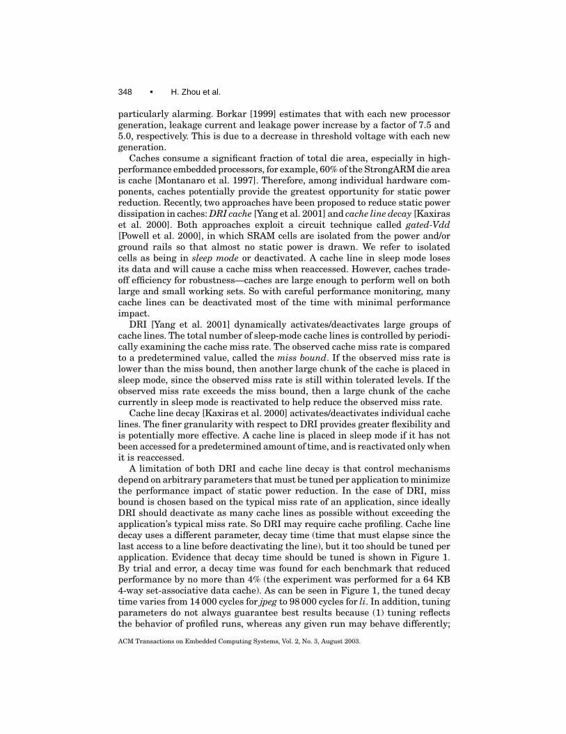
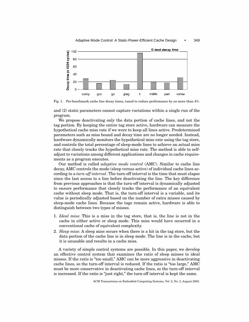
A limitation of both DRI and cache line decay is that control mechanismsdepend on arbitrary parameters that must be tuned per application to minimizethe performance impact of static power reduction. In the case of DRI, missbound is chosen based on the typical miss rate of an application, since ideallyDRI should deactivate as many cache lines as possible without exceeding theapplication’s typical miss rate. So DRI may require cache profiling. Cache linedecay uses a different parameter, decay time (time that must elapse since thelast access to a line before deactivating the line), but it too should be tuned perapplication. Evidence that decay time should be tuned is shown in Figure 1.By trial and error, a decay time was found for each benchmark that reducedperformance by no more than 4% (the experiment was performed for a 64 KB4-way set-associative data cache). As can be seen in Figure 1, the tuned decaytime varies from 14 000 cycles for jpeg to 98 000 cycles for li. In addition, tuningparameters do not always guarantee best results because (1) tuning reflectsthe behavior of profiled runs, whereas any given run may behave differently;
ACM Transactions on Embedded Computing Systems, Vol. 2, No. 3, August 2003.
Adaptive Mode Control: A Static-Power-Efficient Cache Design • 349
Fig. 1. Per-benchmark cache line decay times, tuned to reduce performance by no more than 4%.
and (2) static parameters cannot capture variations within a single run of theprogram.
We propose deactivating only the data portion of cache lines, and not thetag portion. By keeping the entire tag store active, hardware can measure thehypothetical cache miss rate if we were to keep all lines active. Predeterminedparameters such as miss bound and decay time are no longer needed. Instead,hardware dynamically monitors the hypothetical miss rate using the tag store,and controls the total percentage of sleep-mode lines to achieve an actual missrate that closely tracks the hypothetical miss rate. The method is able to self-adjust to variations among different applications and changes in cache require-ments as a program executes.
Our method is called adaptive mode control (AMC). Similar to cache linedecay, AMC controls the mode (sleep versus active) of individual cache lines ac-cording to a turn-off interval. The turn-off interval is the time that must elapsesince the last access to a line before deactivating the line. The key differencefrom previous approaches is that the turn-off interval is dynamically adjustedto ensure performance that closely tracks the performance of an equivalentcache without sleep mode. That is, the turn-off interval is a variable, and itsvalue is periodically adjusted based on the number of extra misses caused bysleep-mode cache lines. Because the tags remain active, hardware is able todistinguish between two types of misses.
1. Ideal miss: This is a miss in the tag store, that is, the line is not in thecache in either active or sleep mode. This miss would have occurred in aconventional cache of equivalent complexity.
2. Sleep miss: A sleep miss occurs when there is a hit in the tag store, but thedata portion of the cache line is in sleep mode. The line is in the cache, butit is unusable and results in a cache miss.
A variety of simple control systems are possible. In this paper, we developan effective control system that examines the ratio of sleep misses to idealmisses. If the ratio is “too small,” AMC can be more aggressive in deactivatingcache lines, so the turn-off interval is reduced. If the ratio is “too large,” AMCmust be more conservative in deactivating cache lines, so the turn-off intervalis increased. If the ratio is “just right,” the turn-off interval is kept the same.
ACM Transactions on Embedded Computing Systems, Vol. 2, No. 3, August 2003.
350 • H. Zhou et al.
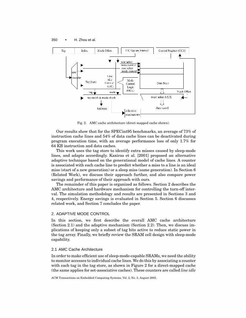
Fig. 2. AMC cache architecture (direct mapped cache shown).
Our results show that for the SPECint95 benchmarks, an average of 73% ofinstruction cache lines and 54% of data cache lines can be deactivated duringprogram execution time, with an average performance loss of only 1.7% for64 KB instruction and data caches.
This work uses the tag store to identify extra misses caused by sleep-modelines, and adapts accordingly. Kaxiras et al. [2001] proposed an alternativeadaptive technique based on the generational model of cache lines. A counteris associated with each cache line to predict whether a miss to a line is an idealmiss (start of a new generation) or a sleep miss (same generation). In Section 6(Related Work), we discuss their approach further, and also compare powersavings and performance of their approach with ours.
The remainder of this paper is organized as follows. Section 2 describes theAMC architecture and hardware mechanism for controlling the turn-off inter-val. The simulation methodology and results are presented in Sections 3 and4, respectively. Energy savings is evaluated in Section 5. Section 6 discussesrelated work, and Section 7 concludes the paper.
2. ADAPTIVE MODE CONTROL
In this section, we first describe the overall AMC cache architecture(Section 2.1) and the adaptive mechanism (Section 2.2). Then, we discuss im-plications of keeping only a subset of tag bits active to reduce static power inthe tag array. Finally, we briefly review the SRAM cell design with sleep-modecapability.
2.1 AMC Cache Architecture
In order to make efficient use of sleep-mode-capable SRAMs, we need the abilityto monitor accesses to individual cache lines. We do this by associating a counterwith each tag in the tag store, as shown in Figure 2 for a direct-mapped cache(the same applies for set-associative caches). These counters are called line idle
ACM Transactions on Embedded Computing Systems, Vol. 2, No. 3, August 2003.
Adaptive Mode Control: A Static-Power-Efficient Cache Design • 351
counters (LICs), because they keep track of how long a cache line has not beenaccessed. If a cache line has been idle (i.e., not accessed) for a sufficient periodof time, it will be placed in sleep mode. Below, we first describe how LICs aremaintained (reset and incremented), and then describe how LICs are monitoredto deactivate lines (LIC compared to a threshold).
A LIC is reset when the corresponding line is accessed. All LICs in the tagstore are simultaneously incremented after a certain number of cycles haveelapsed; this is called the LIC update interval. The LIC update interval isconstant and implementation-dependent, the choice of which depends on astraightforward trade-off between the hardware area/power overhead of LICcounters, and aggressiveness in deactivating cache lines. A sufficiently longLIC update interval (1) results in a small number of bits for each LIC counter,since a single increment represents a longer time interval; and (2) reduces thefrequency of incrementing the counters, keeping their dynamic power contri-bution quite low. However, if the LIC update interval is too long, then AMCis slower to deactivate cache lines, squandering opportunities to save staticpower [Kaxiras et al. 2000]. Detailed analysis in Sections 4.4 and 5 showsthat a LIC update interval of 2048 cycles yields effective results with a smallcounter area overhead and negligible dynamic power overhead (LICs incrementinfrequently—once every 2048 cycles).
Also associated with each tag/LIC is a small comparator logic block, calledthe mode control logic (MCL), as shown in Figure 2. The MCL associated witheach LIC compares the LIC value to the turn-off interval stored in the globalcontrol register (GCR). If the LIC value is greater than or equal to the turn-offinterval in the GCR, the MCL will place the corresponding data line into sleepmode (this is achieved with a control wire, labeled “mode control” in Figure 2).Otherwise, the line remains in active mode.
Note, for write-back data caches, dirty data need to be written back to theL2 cache/main memory before a line is placed in sleep mode because data arenot retained in sleep mode. This may impact performance either positively ornegatively; in some sense, the LIC/MCL logic is an implementation of eagerwriteback [Lee et al. 2000] that suggests it is possible for performance to im-prove. For write-through data caches, there is no need to write data to the L2cache/main memory before deactivating the line, because the write-throughpolicy ensures that the copy in the L2 cache/main memory is up-to-date.
Finally, miss detection is modified slightly in an AMC cache because thereare two types of misses (as described in Section 1), ideal misses and sleep misses.An ideal miss occurs when the tag(s) do not match. A sleep miss occurs when amatching tag is found, but the data portion is in sleep mode. A sleep miss is han-dled like any other cache miss, that is, data must be fetched from the L2 cacheand the cache line is reactivated to hold the fetched data. So ideal misses aremisses that would occur in a conventional cache of equivalent size/associativity,and sleep misses are additional misses introduced by AMC. The goal of AMC isto maximize the number of deactivated lines while minimizing the number ofsleep misses.
The turn-off interval, stored in the GCR, determines how aggressively cachelines are deactivated. When the GCR is too small, many soon-to-be-accessed
ACM Transactions on Embedded Computing Systems, Vol. 2, No. 3, August 2003.
352 • H. Zhou et al.
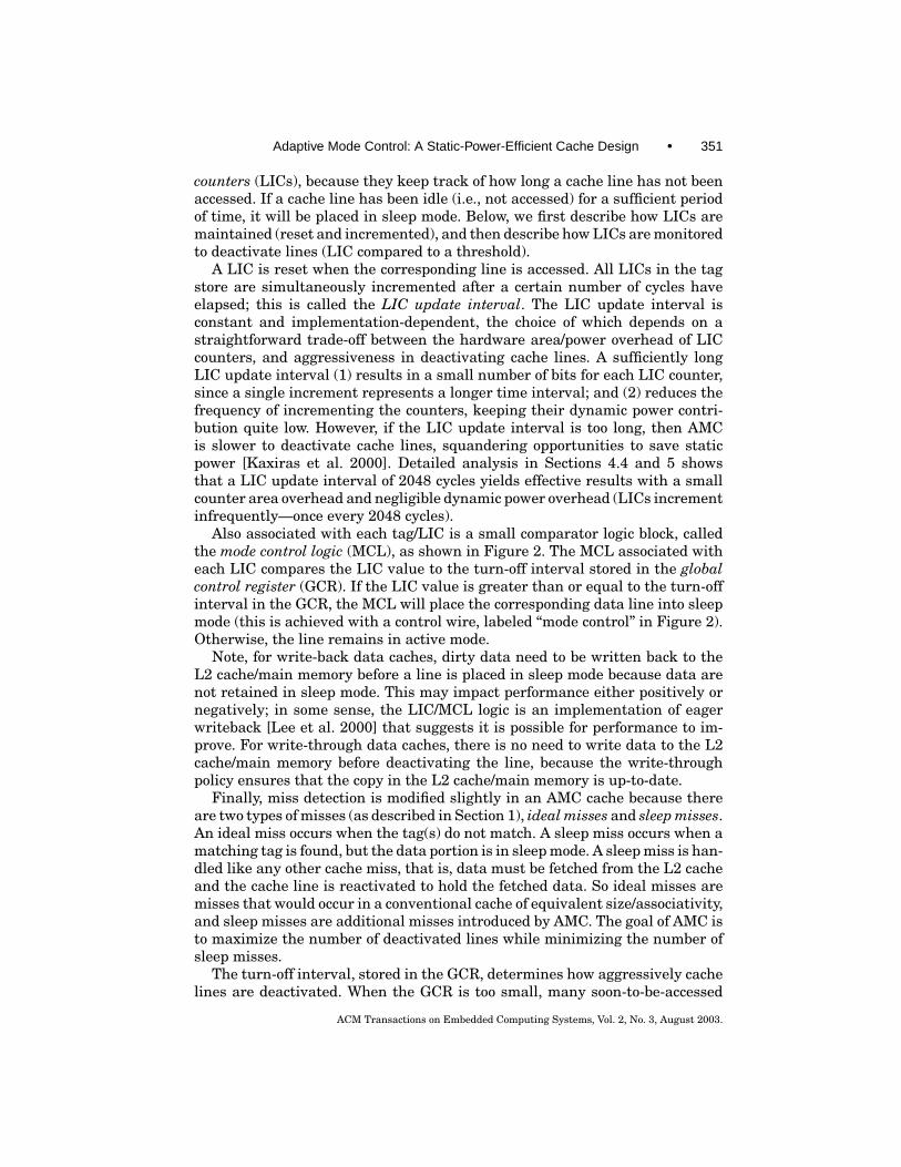
Fig. 3. Adaptive mechanism for dynamically updating the turn-off interval stored in the GCR.
cache lines will prematurely deactivate, resulting in many sleep misses. Inthis case, performance suffers and dynamic power (due to miss servicing) mayincrease. On the other hand, if the GCR is too large, AMC is slow to deactivatelines. Lines that are unused before being evicted are not deactivated earlyenough to reap any static power savings. It is the job of the adaptive mechanism,shown at the bottom of Figure 2, to monitor the overall system and tune the GCRto achieve maximum static power savings with little or no performance loss.
The LIC counters and adaptive control logic consume power themselves andincrease the area of the cache. However, these components consume dynamicpower very intermittently, once every 2048 cycles and 1 million cycles, respec-tively. Therefore, our energy calculations in Section 5 show that the additionaldynamic power is quite small. Static power due to LIC counters is more signif-icant and is calculated in Section 5. As a final point, note that the AMC logicis not on the critical path of tag checking and data access. So AMC does notincrease the hit time of the cache.
2.2 Adaptive Mechanism
The fact that cache tags are never put into sleep mode allows hardware toclassify misses as ideal misses (misses that would have occurred regardless ofa line’s sleep/active status) or sleep misses (extra misses caused by sleep-modelines). (Note: overall misses = ideal misses + sleep misses.)
Ideal and sleep misses are counted during a sense interval, a fixed periodof time. At the end of the sense interval, the adaptive algorithm examines thegathered miss counts and updates the GCR. Then, the miss counters are resetand counting begins anew for the next sense interval.
The adaptive mechanism is shown in Figure 3. The ideal miss counter isincremented when there is a tag miss (tag miss). The sleep miss counter is in-cremented when there is a tag hit and the data is in sleep mode (tag hit anddata sleep). The inputs to the GCR update logic are (1) the ideal miss count,(2) the sleep miss count, (3) the end-of-sense-interval signal, and (4) the perfor-mance factor (PF). The end-of-sense-interval signal simply indicates when theGCR update logic should examine the miss counts and update the GCR. Wewill show in Section 4.4 that the duration of the sense interval has little im-pact on AMC results (both performance and power savings). The performancefactor is set according to the desired balance between performance degradationand static power savings, and it can be controlled using a software-addressableregister.
ACM Transactions on Embedded Computing Systems, Vol. 2, No. 3, August 2003.
Adaptive Mode Control: A Static-Power-Efficient Cache Design • 353
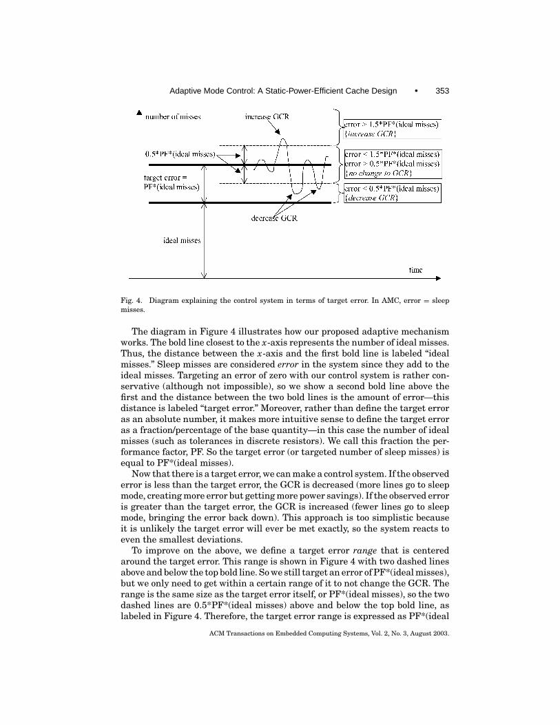
Fig. 4. Diagram explaining the control system in terms of target error. In AMC, error = sleepmisses.
The diagram in Figure 4 illustrates how our proposed adaptive mechanismworks. The bold line closest to the x-axis represents the number of ideal misses.Thus, the distance between the x-axis and the first bold line is labeled “idealmisses.” Sleep misses are considered error in the system since they add to theideal misses. Targeting an error of zero with our control system is rather con-servative (although not impossible), so we show a second bold line above thefirst and the distance between the two bold lines is the amount of error—thisdistance is labeled “target error.” Moreover, rather than define the target erroras an absolute number, it makes more intuitive sense to define the target erroras a fraction/percentage of the base quantity—in this case the number of idealmisses (such as tolerances in discrete resistors). We call this fraction the per-formance factor, PF. So the target error (or targeted number of sleep misses) isequal to PF*(ideal misses).
Now that there is a target error, we can make a control system. If the observederror is less than the target error, the GCR is decreased (more lines go to sleepmode, creating more error but getting more power savings). If the observed erroris greater than the target error, the GCR is increased (fewer lines go to sleepmode, bringing the error back down). This approach is too simplistic becauseit is unlikely the target error will ever be met exactly, so the system reacts toeven the smallest deviations.
To improve on the above, we define a target error range that is centeredaround the target error. This range is shown in Figure 4 with two dashed linesabove and below the top bold line. So we still target an error of PF*(ideal misses),but we only need to get within a certain range of it to not change the GCR. Therange is the same size as the target error itself, or PF*(ideal misses), so the twodashed lines are 0.5*PF*(ideal misses) above and below the top bold line, aslabeled in Figure 4. Therefore, the target error range is expressed as PF*(ideal
ACM Transactions on Embedded Computing Systems, Vol. 2, No. 3, August 2003.
354 • H. Zhou et al.
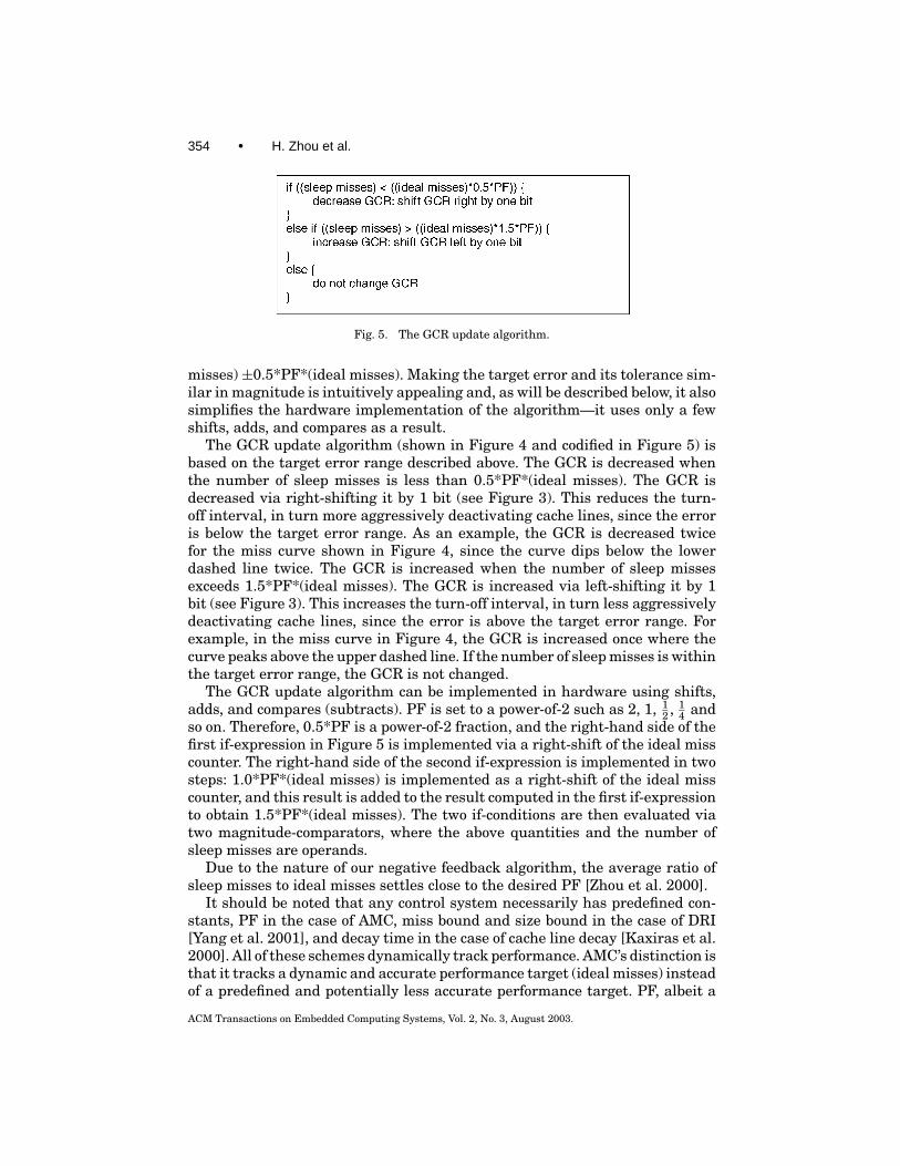
Fig. 5. The GCR update algorithm.
misses) ±0.5*PF*(ideal misses). Making the target error and its tolerance sim-ilar in magnitude is intuitively appealing and, as will be described below, it alsosimplifies the hardware implementation of the algorithm—it uses only a fewshifts, adds, and compares as a result.
The GCR update algorithm (shown in Figure 4 and codified in Figure 5) isbased on the target error range described above. The GCR is decreased whenthe number of sleep misses is less than 0.5*PF*(ideal misses). The GCR isdecreased via right-shifting it by 1 bit (see Figure 3). This reduces the turn-off interval, in turn more aggressively deactivating cache lines, since the erroris below the target error range. As an example, the GCR is decreased twicefor the miss curve shown in Figure 4, since the curve dips below the lowerdashed line twice. The GCR is increased when the number of sleep missesexceeds 1.5*PF*(ideal misses). The GCR is increased via left-shifting it by 1bit (see Figure 3). This increases the turn-off interval, in turn less aggressivelydeactivating cache lines, since the error is above the target error range. Forexample, in the miss curve in Figure 4, the GCR is increased once where thecurve peaks above the upper dashed line. If the number of sleep misses is withinthe target error range, the GCR is not changed.
The GCR update algorithm can be implemented in hardware using shifts,adds, and compares (subtracts). PF is set to a power-of-2 such as 2, 1, 1
2 , 14 and
so on. Therefore, 0.5*PF is a power-of-2 fraction, and the right-hand side of thefirst if-expression in Figure 5 is implemented via a right-shift of the ideal misscounter. The right-hand side of the second if-expression is implemented in twosteps: 1.0*PF*(ideal misses) is implemented as a right-shift of the ideal misscounter, and this result is added to the result computed in the first if-expressionto obtain 1.5*PF*(ideal misses). The two if-conditions are then evaluated viatwo magnitude-comparators, where the above quantities and the number ofsleep misses are operands.
Due to the nature of our negative feedback algorithm, the average ratio ofsleep misses to ideal misses settles close to the desired PF [Zhou et al. 2000].
It should be noted that any control system necessarily has predefined con-stants, PF in the case of AMC, miss bound and size bound in the case of DRI[Yang et al. 2001], and decay time in the case of cache line decay [Kaxiras et al.2000]. All of these schemes dynamically track performance. AMC’s distinction isthat it tracks a dynamic and accurate performance target (ideal misses) insteadof a predefined and potentially less accurate performance target. PF, albeit a
ACM Transactions on Embedded Computing Systems, Vol. 2, No. 3, August 2003.
Adaptive Mode Control: A Static-Power-Efficient Cache Design • 355
Fig. 6. SRAM cell with sleep-mode support.
predefined parameter, is a multiplicative coefficient and determines how closelyAMC performance tracks hypothetical performance.
2.3 Using Partial Tags
The method discussed in Section 2.2 keeps the full tag array active to preciselyclassify misses as either ideal misses or sleep misses. A disadvantage of keepingtags active is that the tags always consume static power.
Static power consumption in the tag array can be reduced by keeping only apart of the tag active when the corresponding cache line is in sleep mode, in ex-change for less precise miss classification. When a deactivated line is accessed,only the tag bits that are active are checked to determine whether the miss isan ideal miss or a sleep miss.
If complete tags are used, a tag match indicates that a miss is definitelya sleep miss. However, if partial tags are used, a tag match indicates that amiss may be a sleep miss. AMC must conservatively classify it as a sleep miss.Because some ideal misses are misclassified as sleep misses, the measured sleepmiss rate is larger than it actually is, and AMC overcompensates by turning offfewer cache lines. So using partial tags trades static power savings in the dataarray for static power savings in the tag array. This trade-off is investigated inSection 4.6.
2.4 Review of SRAM Cell with Sleep-Mode Capability
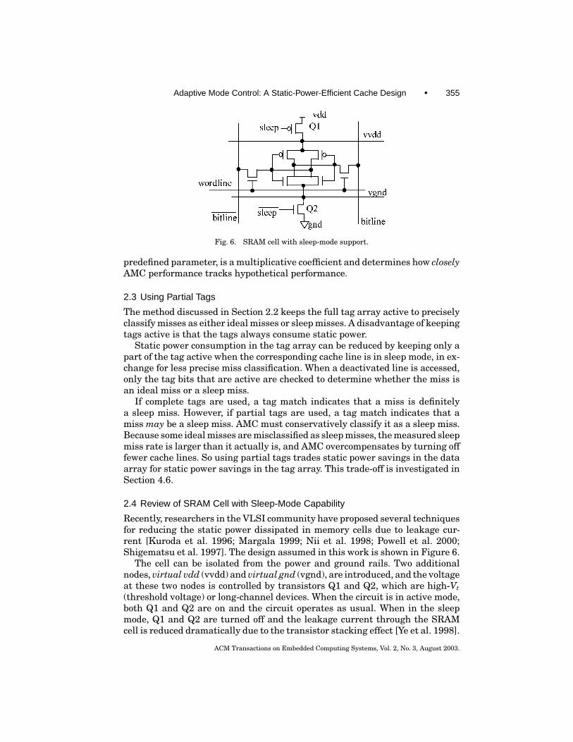
Recently, researchers in the VLSI community have proposed several techniquesfor reducing the static power dissipated in memory cells due to leakage cur-rent [Kuroda et al. 1996; Margala 1999; Nii et al. 1998; Powell et al. 2000;Shigematsu et al. 1997]. The design assumed in this work is shown in Figure 6.
The cell can be isolated from the power and ground rails. Two additionalnodes, virtual vdd (vvdd) and virtual gnd (vgnd), are introduced, and the voltageat these two nodes is controlled by transistors Q1 and Q2, which are high-Vt(threshold voltage) or long-channel devices. When the circuit is in active mode,both Q1 and Q2 are on and the circuit operates as usual. When in the sleepmode, Q1 and Q2 are turned off and the leakage current through the SRAMcell is reduced dramatically due to the transistor stacking effect [Ye et al. 1998].
ACM Transactions on Embedded Computing Systems, Vol. 2, No. 3, August 2003.
356 • H. Zhou et al.
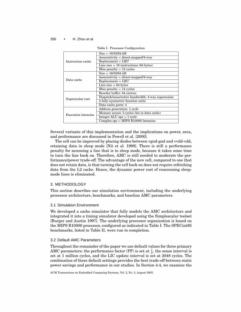
Table I. Processor Configuration
Instruction cache
Size = 16/32/64 kBAssociativity = direct-mapped/4-wayReplacement = LRULine size = 16 instructions (64 bytes)Miss penalty = 12 cycles
Data cache
Size = 16/32/64 kBAssociativity = direct-mapped/4-wayReplacement = LRULine size = 64 bytesMiss penalty = 14 cycles
Superscalar core
Reorder buffer: 64 entriesDispatch/issue/retire bandwidth: 4-way superscalar4 fully-symmetric function unitsData cache ports: 4
Execution latencies
Address generation: 1 cycleMemory access: 2 cycles (hit in data cache)Integer ALU ops = 1 cycleComplex ops =MIPS R10000 latencies
Several variants of this implementation and the implications on power, area,and performance are discussed in Powell et al. [2000].
The cell can be improved by placing diodes between vgnd-gnd and vvdd-vdd,retaining data in sleep mode [Nii et al. 1998]. There is still a performancepenalty for accessing a line that is in sleep mode, because it takes some timeto turn the line back on. Therefore, AMC is still needed to moderate the per-formance/power trade-off. The advantage of the new cell, compared to one thatdoes not retain data, is that turning the cell back on does not require refetchingdata from the L2 cache. Hence, the dynamic power cost of reaccessing sleep-mode lines is eliminated.
3. METHODOLOGY
This section describes our simulation environment, including the underlyingprocessor architecture, benchmarks, and baseline AMC parameters.
3.1 Simulation Environment
We developed a cache simulator that fully models the AMC architecture andintegrated it into a timing simulator developed using the Simplescalar toolset[Burger and Austin 1997]. The underlying processor organization is based onthe MIPS R10000 processor, configured as indicated in Table I. The SPECint95benchmarks, listed in Table II, were run to completion.
3.2 Default AMC Parameters
Throughout the remainder of the paper we use default values for three primaryAMC parameters: the performance factor (PF) is set at 1
2 , the sense interval isset at 1 million cycles, and the LIC update interval is set at 2048 cycles. Thecombination of these default settings provides the best trade-off between staticpower savings and performance in our studies. In Section 4.4, we examine the
ACM Transactions on Embedded Computing Systems, Vol. 2, No. 3, August 2003.

Adaptive Mode Control: A Static-Power-Efficient Cache Design • 357
Table II. Benchmarks
Benchmark Input Dataset Instruction Count (in million)compress compress95.ref 24gcc −O3 genrecog.i –o genrecog.s 117go 99 133jpeg vigo.ppm 166li test.lsp (queens 7) 202m88ksim −c < ctl.in (dcrand.big) 120perl scrabble.pl < scrabble.in (dictionary) 108vortex vortex.in (persons.250, bendian.*) 101
impact of varying each of these parameters individually on static power andperformance. The lower and upper bounds of the turn-off interval stored in theGCR are 4k and 128k cycles, respectively.
4. RESULTS
In this section, we apply AMC to L1 instruction caches (I-caches) and datacaches (D-caches), separately and together. Specifically, we examine the perfor-mance impact of AMC and the percentage of cache lines that are placed in sleepmode. Performance is measured as instructions-per-cycle (IPC), and we presentthe % IPC degradation. The percentage of cache lines that are placed in sleepmode is called the turn-off ratio. Turn-off ratio is measured by recording thefraction of cache lines in sleep-mode each cycle, and averaging over all cycles.We assume static power savings is proportional to the turn-off ratio.
4.1 AMC Instruction Caches
We studied 16 kB, 32 kB, and 64 kB instruction caches for each of direct mappedand 4-way set-associativity. The D-cache in all experiments is 64 kB 4-way set-associative without AMC.
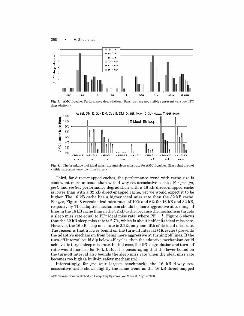
Figure 7 shows % IPC degradation over all benchmarks and I-cache con-figurations. Figure 8 shows the corresponding miss rates, broken down intothe sleep miss rate and ideal miss rate. The primary result from Figure 7, asexpected, is that performance is never degraded by more than 6.5%, and per-formance is never worsened by more than 3% on average.
Figure 7 also shows that the performance impact of AMC is sensitive toI-cache size and associativity. First, performance impact is less with higherassociativity. There are fewer ideal misses with 4-way set-associative cachesthan with direct-mapped caches, and our control system targets a number ofsleep misses proportional to the number of ideal misses via PF. This is a smallprice we pay for using a multiplicative coefficient rather than an arbitrarily set,an absolute bound on the number of sleep misses. In Section 4.4, we study theeffects of varying PF on both static power and performance.
Second, with 4-way set-associative caches, increasing cache size resultsin less performance degradation (except for a small deviation in gcc for the32 kB cache), for the same reason just described: larger caches have fewerideal misses and our control system will generate fewer sleep misses as aresult.
ACM Transactions on Embedded Computing Systems, Vol. 2, No. 3, August 2003.
358 • H. Zhou et al.
Fig. 7. AMC I-cache: Performance degradation. (Bars that are not visible represent very low IPCdegradation.)
Fig. 8. The breakdown of ideal miss rate and sleep miss rate for AMC I-caches. (Bars that are notvisible represent very low miss rates.)
Third, for direct-mapped caches, the performance trend with cache size issomewhat more unusual than with 4-way set-associative caches. For gcc, go,perl, and vortex, performance degradation with a 16 kB direct-mapped cacheis lower than with a 32 kB direct-mapped cache, yet we would expect it to behigher. The 16 kB cache has a higher ideal miss rate than the 32 kB cache.For gcc, Figure 8 reveals ideal miss rates of 10% and 6% for 16 kB and 32 kB,respectively. The adaptive mechanism should be more aggressive at turning offlines in the 16 kB cache than in the 32 kB cache, because the mechanism targetsa sleep miss rate equal to PF* ideal miss rate, where PF = 1
2 . Figure 8 showsthat the 32 kB sleep miss rate is 2.7%, which is about half of its ideal miss rate.However, the 16 kB sleep miss rate is 2.2%, only one-fifth of its ideal miss rate.The reason is that a lower bound on the turn-off interval (4K cycles) preventsthe adaptive mechanism from being more aggressive at turning off lines. If theturn-off interval could dip below 4K cycles, then the adaptive mechanism couldachieve its target sleep miss rate. In that case, the IPC degradation and turn-offratio would increase for 16 kB. But it is encouraging that the lower bound onthe turn-off interval also bounds the sleep miss rate when the ideal miss ratebecomes too high (a built-in safety mechanism).
Interestingly, for gcc (our largest benchmark), the 16 kB 4-way set-associative cache shows slightly the same trend as the 16 kB direct-mapped
ACM Transactions on Embedded Computing Systems, Vol. 2, No. 3, August 2003.
Adaptive Mode Control: A Static-Power-Efficient Cache Design • 359
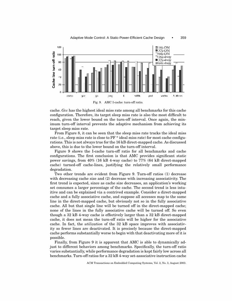
Fig. 9. AMC I-cache: turn-off ratio.
cache. Gcc has the highest ideal miss rate among all benchmarks for this cacheconfiguration. Therefore, its target sleep miss rate is also the most difficult toreach, given the lower bound on the turn-off interval. Once again, the min-imum turn-off interval prevents the adaptive mechanism from achieving itstarget sleep miss rate.
From Figure 8, it can be seen that the sleep miss rate tracks the ideal missrate (i.e., sleep miss rate is close to PF * ideal miss rate) for most cache configu-rations. This is not always true for the 16 kB direct-mapped cache. As discussedabove, this is due to the lower bound on the turn-off interval.
Figure 9 shows the I-cache turn-off ratio for all benchmarks and cacheconfigurations. The first conclusion is that AMC provides significant staticpower savings, from 40% (16 kB 4-way cache) to 77% (64 kB direct-mappedcache) turned-off cache-lines, justifying the relatively small performancedegradation.
Two other trends are evident from Figure 9. Turn-off ratios (1) decreasewith decreasing cache size and (2) decrease with increasing associativity. Thefirst trend is expected, since as cache size decreases, an application’s workingset consumes a larger percentage of the cache. The second trend is less intu-itive and can be explained via a contrived example. Consider a direct-mappedcache and a fully associative cache, and suppose all accesses map to the sameline in the direct-mapped cache, but obviously not so in the fully associativecache. All but that single line will be turned off in the direct-mapped cache;none of the lines in the fully associative cache will be turned off. So eventhough a 32 kB 4-way cache is effectively larger than a 32 kB direct-mappedcache, it does not mean the turn-off ratio will be higher for the associativecache. In fact, the utilization of the 32 kB space improves with associativ-ity so fewer lines are deactivated. It is precisely because the direct-mappedcache performs substantially worse to begin with that deactivating more of it ispossible.
Finally, from Figure 9 it is apparent that AMC is able to dynamically ad-just to different behaviors among benchmarks. Specifically, the turn-off ratiovaries substantially, while performance degradation is kept fairly low across allbenchmarks. Turn-off ratios for a 32 kB 4-way set-associative instruction cache
ACM Transactions on Embedded Computing Systems, Vol. 2, No. 3, August 2003.
360 • H. Zhou et al.
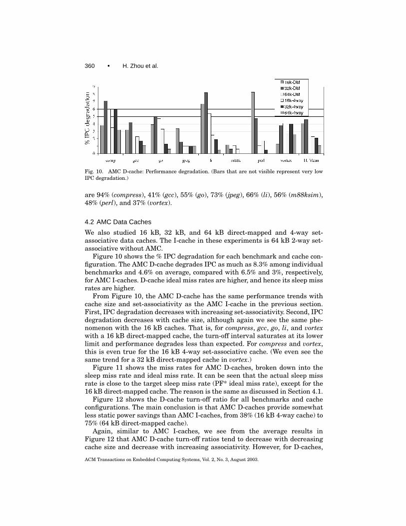
Fig. 10. AMC D-cache: Performance degradation. (Bars that are not visible represent very lowIPC degradation.)
are 94% (compress), 41% (gcc), 55% (go), 73% (jpeg), 66% (li), 56% (m88ksim),48% (perl), and 37% (vortex).
4.2 AMC Data Caches
We also studied 16 kB, 32 kB, and 64 kB direct-mapped and 4-way set-associative data caches. The I-cache in these experiments is 64 kB 2-way set-associative without AMC.
Figure 10 shows the % IPC degradation for each benchmark and cache con-figuration. The AMC D-cache degrades IPC as much as 8.3% among individualbenchmarks and 4.6% on average, compared with 6.5% and 3%, respectively,for AMC I-caches. D-cache ideal miss rates are higher, and hence its sleep missrates are higher.
From Figure 10, the AMC D-cache has the same performance trends withcache size and set-associativity as the AMC I-cache in the previous section.First, IPC degradation decreases with increasing set-associativity. Second, IPCdegradation decreases with cache size, although again we see the same phe-nomenon with the 16 kB caches. That is, for compress, gcc, go, li, and vortexwith a 16 kB direct-mapped cache, the turn-off interval saturates at its lowerlimit and performance degrades less than expected. For compress and vortex,this is even true for the 16 kB 4-way set-associative cache. (We even see thesame trend for a 32 kB direct-mapped cache in vortex.)
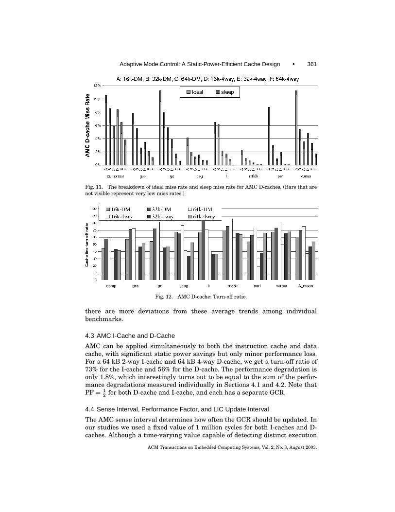
Figure 11 shows the miss rates for AMC D-caches, broken down into thesleep miss rate and ideal miss rate. It can be seen that the actual sleep missrate is close to the target sleep miss rate (PF* ideal miss rate), except for the16 kB direct-mapped cache. The reason is the same as discussed in Section 4.1.
Figure 12 shows the D-cache turn-off ratio for all benchmarks and cacheconfigurations. The main conclusion is that AMC D-caches provide somewhatless static power savings than AMC I-caches, from 38% (16 kB 4-way cache) to75% (64 kB direct-mapped cache).
Again, similar to AMC I-caches, we see from the average results inFigure 12 that AMC D-cache turn-off ratios tend to decrease with decreasingcache size and decrease with increasing associativity. However, for D-caches,
ACM Transactions on Embedded Computing Systems, Vol. 2, No. 3, August 2003.
Adaptive Mode Control: A Static-Power-Efficient Cache Design • 361
Fig. 11. The breakdown of ideal miss rate and sleep miss rate for AMC D-caches. (Bars that arenot visible represent very low miss rates.)
Fig. 12. AMC D-cache: Turn-off ratio.
there are more deviations from these average trends among individualbenchmarks.
4.3 AMC I-Cache and D-Cache
AMC can be applied simultaneously to both the instruction cache and datacache, with significant static power savings but only minor performance loss.For a 64 kB 2-way I-cache and 64 kB 4-way D-cache, we get a turn-off ratio of73% for the I-cache and 56% for the D-cache. The performance degradation isonly 1.8%, which interestingly turns out to be equal to the sum of the perfor-mance degradations measured individually in Sections 4.1 and 4.2. Note thatPF = 1
2 for both D-cache and I-cache, and each has a separate GCR.
4.4 Sense Interval, Performance Factor, and LIC Update Interval
The AMC sense interval determines how often the GCR should be updated. Inour studies we used a fixed value of 1 million cycles for both I-caches and D-caches. Although a time-varying value capable of detecting distinct execution
ACM Transactions on Embedded Computing Systems, Vol. 2, No. 3, August 2003.
362 • H. Zhou et al.
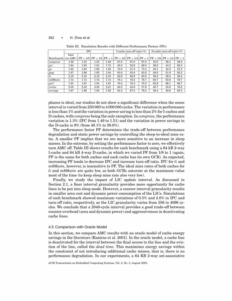
Table III. Simulation Results with Different Performance Factors (PFs)
IPC I-cache turn-off ratio (%) D-cache turn-off ratio (%)base
Benchmark (no AMC) PF = 1/8 PF = 1/4 PF = 1 PF = 1/8 PF = 1/4 PF = 1 PF = 1/8 PF = 1/4 PF = 1compress 1.56 1.53 1.53 1.49 97.0 97.0 97.0 35.0 36.3 46.8gcc 1.84 1.83 1.81 1.74 45.2 52.9 66.0 36.5 44.3 60.3go 1.64 1.63 1.62 1.58 15.8 31.3 73.4 40.1 42.2 53.3jpeg 1.97 1.96 1.95 1.94 83.8 83.8 83.9 48.0 51.9 62.3li 2.19 2.18 2.18 2.18 82.9 82.9 83.0 36.4 36.4 36.4m88ksim 1.74 1.74 1.74 1.74 78.1 78.3 78.7 63.7 63.8 79.7perl 1.91 1.91 1.91 1.91 70.2 70.3 70.3 65.8 66.1 66.7vortex 2.35 2.32 2.30 2.21 40.5 43.6 57.6 45.7 55.6 76.8average 1.87 1.86 1.85 1.82 64.2 67.5 76.2 46.4 49.6 60.3
phases is ideal, our studies do not show a significant difference when the senseinterval is varied from 250 000 to 4 000 000 cycles. The variation in performanceis less than 1% and the variation in power saving is less than 2% for I-caches andD-caches, with compress being the only exception. In compress, the performancevariation is 1.3% (IPC from 1.49 to 1.51) and the variation in power savings inthe D-cache is 9% (from 48.1% to 39.0%).
The performance factor PF determines the trade-off between performancedegradation and static power savings by controlling the sleep-to-ideal miss ra-tio. A smaller PF implies that we are more sensitive to an increase in sleepmisses. In the extreme, by setting the performance factor to zero, we effectivelyturn AMC off. Table III shows results for each benchmark using a 64 kB 2-wayI-cache and 64 kB 4-way D-cache, in which we varied PF from 1/8 to 1 (again,PF is the same for both caches and each cache has its own GCR). As expected,increasing PF tends to decrease IPC and increase turn-off ratio. IPC for li andm88ksim, however, is insensitive to PF. The ideal miss rates of both caches forli and m88ksim are quite low, so both GCRs saturate at the maximum valuemost of the time (to keep sleep miss rate also very low).
Finally, we study the impact of LIC update interval. As discussed inSection 2.1, a finer interval granularity provides more opportunity for cachelines to be put into sleep mode. However, a coarser interval granularity resultsin smaller area cost and dynamic power consumption of the LICs. Simulationsof each benchmark showed maximum variations of 0.5% and 2.0% in IPC andturn-off ratio, respectively, as the LIC granularity varies from 256 to 4096 cy-cles. We conclude that a 2048-cycle interval provides a good trade-off betweencounter overhead (area and dynamic power) and aggressiveness in deactivatingcache lines.
4.5 Comparison with Oracle Model
In this section, we compare AMC results with an oracle model of cache energysavings in the literature [Kaxiras et al. 2001]. In the oracle model, a cache lineis deactivated for the interval between the final access to the line and the evic-tion of the line, called the dead time. This maximizes energy savings withinthe constraint of not introducing additional cache misses, that is, there is noperformance degradation. In our experiments, a 64 KB 2-way set-associative
ACM Transactions on Embedded Computing Systems, Vol. 2, No. 3, August 2003.
Adaptive Mode Control: A Static-Power-Efficient Cache Design • 363
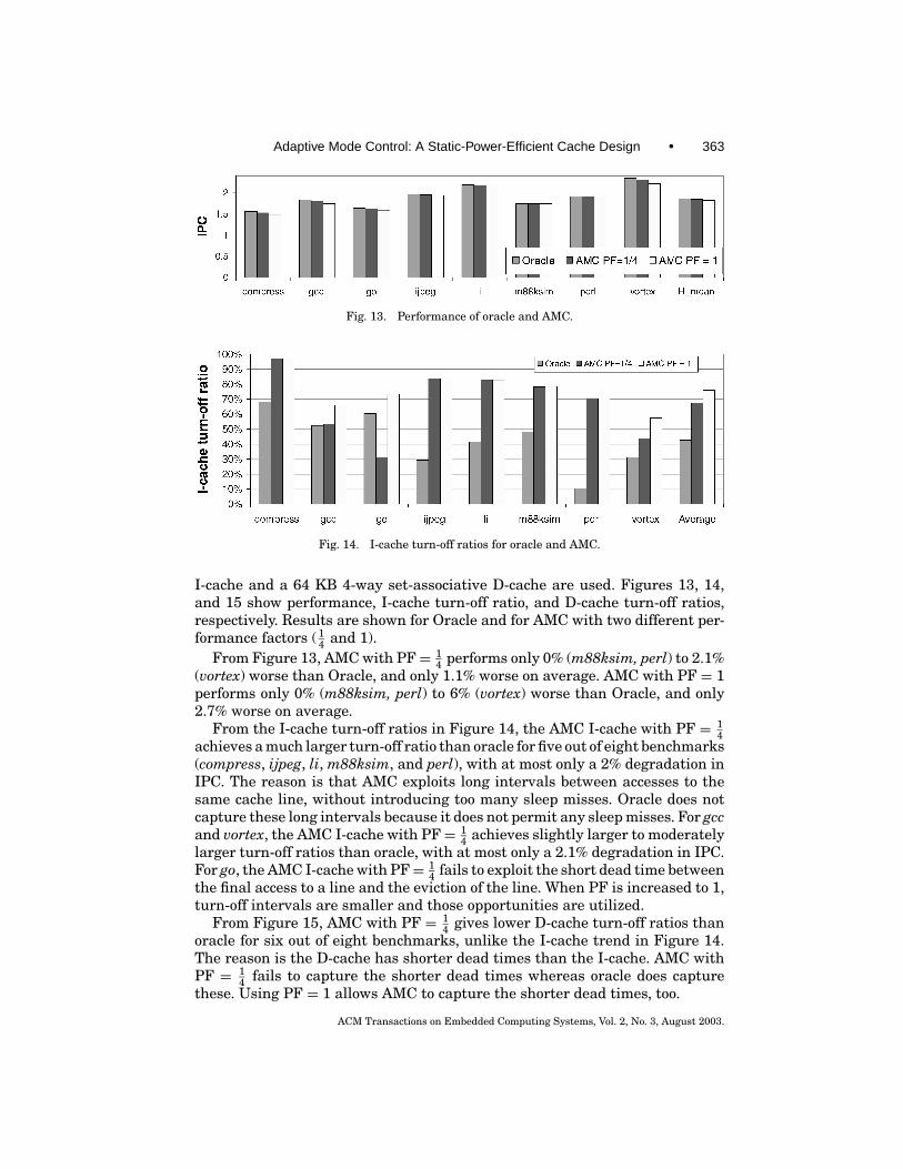
Fig. 13. Performance of oracle and AMC.
Fig. 14. I-cache turn-off ratios for oracle and AMC.
I-cache and a 64 KB 4-way set-associative D-cache are used. Figures 13, 14,and 15 show performance, I-cache turn-off ratio, and D-cache turn-off ratios,respectively. Results are shown for Oracle and for AMC with two different per-formance factors ( 1
4 and 1).From Figure 13, AMC with PF= 1
4 performs only 0% (m88ksim, perl) to 2.1%(vortex) worse than Oracle, and only 1.1% worse on average. AMC with PF = 1performs only 0% (m88ksim, perl) to 6% (vortex) worse than Oracle, and only2.7% worse on average.
From the I-cache turn-off ratios in Figure 14, the AMC I-cache with PF = 14
achieves a much larger turn-off ratio than oracle for five out of eight benchmarks(compress, ijpeg, li, m88ksim, and perl), with at most only a 2% degradation inIPC. The reason is that AMC exploits long intervals between accesses to thesame cache line, without introducing too many sleep misses. Oracle does notcapture these long intervals because it does not permit any sleep misses. For gccand vortex, the AMC I-cache with PF= 1
4 achieves slightly larger to moderatelylarger turn-off ratios than oracle, with at most only a 2.1% degradation in IPC.For go, the AMC I-cache with PF= 1
4 fails to exploit the short dead time betweenthe final access to a line and the eviction of the line. When PF is increased to 1,turn-off intervals are smaller and those opportunities are utilized.
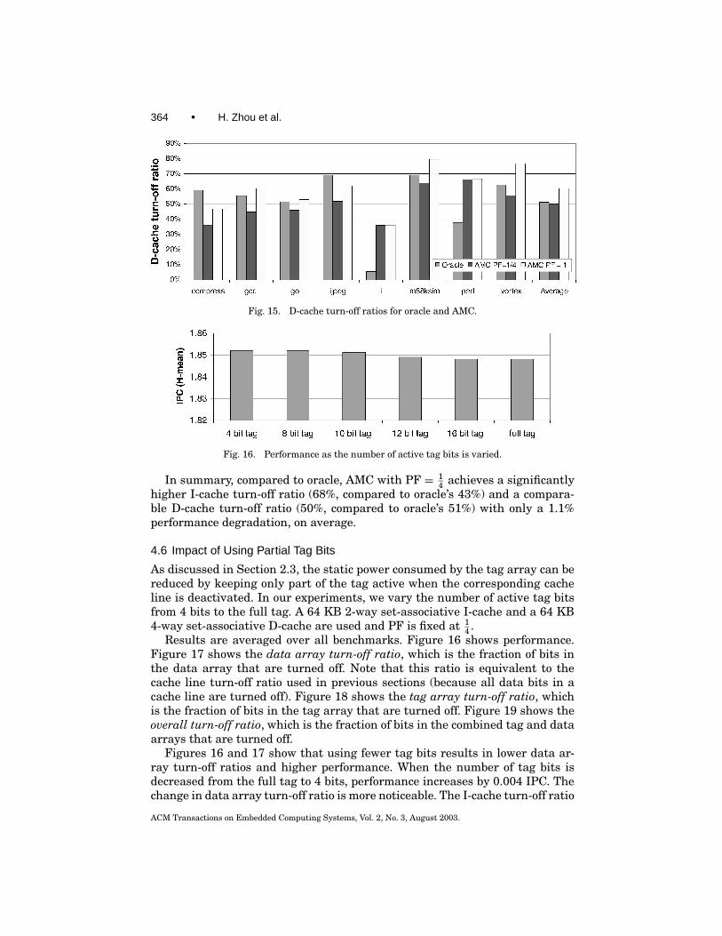
From Figure 15, AMC with PF = 14 gives lower D-cache turn-off ratios than
oracle for six out of eight benchmarks, unlike the I-cache trend in Figure 14.The reason is the D-cache has shorter dead times than the I-cache. AMC withPF = 1
4 fails to capture the shorter dead times whereas oracle does capturethese. Using PF = 1 allows AMC to capture the shorter dead times, too.
ACM Transactions on Embedded Computing Systems, Vol. 2, No. 3, August 2003.
364 • H. Zhou et al.
Fig. 15. D-cache turn-off ratios for oracle and AMC.
Fig. 16. Performance as the number of active tag bits is varied.
In summary, compared to oracle, AMC with PF = 14 achieves a significantly
higher I-cache turn-off ratio (68%, compared to oracle’s 43%) and a compara-ble D-cache turn-off ratio (50%, compared to oracle’s 51%) with only a 1.1%performance degradation, on average.
4.6 Impact of Using Partial Tag Bits
As discussed in Section 2.3, the static power consumed by the tag array can bereduced by keeping only part of the tag active when the corresponding cacheline is deactivated. In our experiments, we vary the number of active tag bitsfrom 4 bits to the full tag. A 64 KB 2-way set-associative I-cache and a 64 KB4-way set-associative D-cache are used and PF is fixed at 1
4 .Results are averaged over all benchmarks. Figure 16 shows performance.
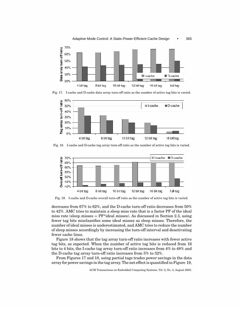
Figure 17 shows the data array turn-off ratio, which is the fraction of bits inthe data array that are turned off. Note that this ratio is equivalent to thecache line turn-off ratio used in previous sections (because all data bits in acache line are turned off). Figure 18 shows the tag array turn-off ratio, whichis the fraction of bits in the tag array that are turned off. Figure 19 shows theoverall turn-off ratio, which is the fraction of bits in the combined tag and dataarrays that are turned off.
Figures 16 and 17 show that using fewer tag bits results in lower data ar-ray turn-off ratios and higher performance. When the number of tag bits isdecreased from the full tag to 4 bits, performance increases by 0.004 IPC. Thechange in data array turn-off ratio is more noticeable. The I-cache turn-off ratio
ACM Transactions on Embedded Computing Systems, Vol. 2, No. 3, August 2003.
Adaptive Mode Control: A Static-Power-Efficient Cache Design • 365
Fig. 17. I-cache and D-cache data array turn-off ratio as the number of active tag bits is varied.
Fig. 18. I-cache and D-cache tag array turn-off ratio as the number of active tag bits is varied.
Fig. 19. I-cache and D-cache overall turn-off ratio as the number of active tag bits is varied.
decreases from 67% to 62%, and the D-cache turn-off ratio decreases from 50%to 42%. AMC tries to maintain a sleep miss rate that is a factor PF of the idealmiss rate (sleep misses = PF*ideal misses). As discussed in Section 2.3, usingfewer tag bits misclassifies some ideal misses as sleep misses. Therefore, thenumber of ideal misses is underestimated, and AMC tries to reduce the numberof sleep misses accordingly by increasing the turn-off interval and deactivatingfewer cache lines.
Figure 18 shows that the tag array turn-off ratio increases with fewer activetag bits, as expected. When the number of active tag bits is reduced from 16bits to 4 bits, the I-cache tag array turn-off ratio increases from 4% to 48% andthe D-cache tag array turn-off ratio increases from 5% to 32%.
From Figures 17 and 18, using partial tags trades power savings in the dataarray for power savings in the tag array. The net effect is quantified in Figure 19,
ACM Transactions on Embedded Computing Systems, Vol. 2, No. 3, August 2003.
366 • H. Zhou et al.
which shows the overall turn-off ratio. For the I-cache, there is a slight increasein overall static power savings if 12 bits are used instead of the full tag.However, the improvement is minimal. For the D-cache, using fewer thanthe full number of tag bits always reduces the overall static power savings.The reason is the static power consumed by the tag array is very small(3.3%) compared to the static power consumed by the data array, in our cacheconfiguration. The number of tag bits for the I-cache and D-cache is 17 and 18,respectively, and the number of bits in the data portion of the line is 512.
In summary, while using partial tags saves static power in the tag array,it reduces static power savings in the data array and the net effect does notvalidate its effectiveness. The conclusion may differ for smaller cache line sizes,where the number of tag bits is a significant fraction of the cache line.
5. ENERGY ANALYSIS
In this section, we evaluate the overall energy savings of AMC, taking intoaccount the energy overhead of the additional AMC logic. We base our analysison experiments using the Compaq 21264 I-cache, a 64 KB 2-way set-associativecache implemented in a 0.35 µm CMOS process. In Section 5.1, we discuss theinput parameters to our analysis and calculate the energy overhead of the LICand MCL logic. In Sections 5.2 and 5.3, we determine the total energy savings ofAMC at the cache level and the processor level, respectively. We find that AMC,implemented in a 64 KB 2-way set-associative I-cache using a 0.35 µm process,yields energy savings of 6.4% at the cache level and 2.0% at the processorlevel. The savings are expected to be much higher in future deep submicrontechnologies.
5.1 Parameters Used in the Energy Analysis
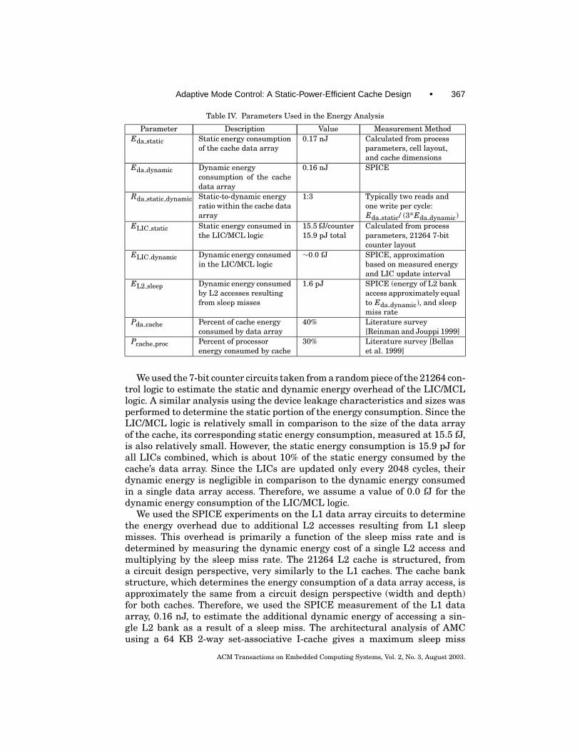
In order to determine the overall energy savings of AMC, we need values forthe parameters listed in Table IV. For each parameter, Table IV gives the pa-rameter’s name, a brief description, its value, and the method used to measurethe value.
The static energy consumption of the cache data array was calculated fromthe 0.35 µm leakage current curves for n-type and p-type transistors as definedin the process specification and the device widths of the data array SRAM cells.This calculation, when factored by the data array dimensions, yielded a totalstatic energy consumption of 0.17 nJ. To determine values for the next fiveparameters in the table, we performed a series of SPICE experiments usinglayout-extracted SRAM cells and 7-bit counters taken from the 21264 I-cacheand control logic. We first measured the dynamic energy consumed in a singledata array read or write access by isolating the energy consumed in the bit-lines, wordlines, and within the SRAM cell itself. This resulted in a dynamicenergy consumption of 0.16 nJ. Because the 21264 I-cache typically performsthree transactions within a single cycle (two reads and one write), the static-to-dynamic energy ratio of the I-cache data array is 1:3. It is important to notehere that this ratio will increase dramatically as process technology shrinks[Bellas et al. 1999]. The effects of this will be discussed later in this section.
ACM Transactions on Embedded Computing Systems, Vol. 2, No. 3, August 2003.
Adaptive Mode Control: A Static-Power-Efficient Cache Design • 367
Table IV. Parameters Used in the Energy Analysis
Parameter Description Value Measurement MethodEda static Static energy consumption
of the cache data array0.17 nJ Calculated from process
parameters, cell layout,and cache dimensions
Eda dynamic Dynamic energyconsumption of the cachedata array
0.16 nJ SPICE
Rda static dynamic Static-to-dynamic energyratio within the cache dataarray
1:3 Typically two reads andone write per cycle:Eda static/ (3*Eda dynamic)
ELIC static Static energy consumed inthe LIC/MCL logic
15.5 fJ/counter15.9 pJ total
Calculated from processparameters, 21264 7-bitcounter layout
ELIC dynamic Dynamic energy consumedin the LIC/MCL logic
∼0.0 fJ SPICE, approximationbased on measured energyand LIC update interval
EL2 sleep Dynamic energy consumedby L2 accesses resultingfrom sleep misses
1.6 pJ SPICE (energy of L2 bankaccess approximately equalto Eda dynamic), and sleepmiss rate
Pda cache Percent of cache energyconsumed by data array
40% Literature survey[Reinman and Jouppi 1999]
Pcache proc Percent of processorenergy consumed by cache
30% Literature survey [Bellaset al. 1999]
We used the 7-bit counter circuits taken from a random piece of the 21264 con-trol logic to estimate the static and dynamic energy overhead of the LIC/MCLlogic. A similar analysis using the device leakage characteristics and sizes wasperformed to determine the static portion of the energy consumption. Since theLIC/MCL logic is relatively small in comparison to the size of the data arrayof the cache, its corresponding static energy consumption, measured at 15.5 fJ,is also relatively small. However, the static energy consumption is 15.9 pJ forall LICs combined, which is about 10% of the static energy consumed by thecache’s data array. Since the LICs are updated only every 2048 cycles, theirdynamic energy is negligible in comparison to the dynamic energy consumedin a single data array access. Therefore, we assume a value of 0.0 fJ for thedynamic energy consumption of the LIC/MCL logic.
We used the SPICE experiments on the L1 data array circuits to determinethe energy overhead due to additional L2 accesses resulting from L1 sleepmisses. This overhead is primarily a function of the sleep miss rate and isdetermined by measuring the dynamic energy cost of a single L2 access andmultiplying by the sleep miss rate. The 21264 L2 cache is structured, froma circuit design perspective, very similarly to the L1 caches. The cache bankstructure, which determines the energy consumption of a data array access, isapproximately the same from a circuit design perspective (width and depth)for both caches. Therefore, we used the SPICE measurement of the L1 dataarray, 0.16 nJ, to estimate the additional dynamic energy of accessing a sin-gle L2 bank as a result of a sleep miss. The architectural analysis of AMCusing a 64 KB 2-way set-associative I-cache gives a maximum sleep miss
ACM Transactions on Embedded Computing Systems, Vol. 2, No. 3, August 2003.
368 • H. Zhou et al.
rate across all benchmarks of 1%. This yields a total L2 access overhead of1.6 pJ.
Finally, we used data taken from the literature to estimate the contribu-tion of data array energy consumption to total cache consumption [Reinmanand Jouppi 1999] and the contribution of total cache consumption to proces-sor consumption [Bellas et al. 1999]. In developing the CACTI cache analysistool, Reinman and Jouppi [1999] found that the data array is responsible forapproximately 40% of the total cache energy. Bellas et al. [1999] estimate thatthe cache contributes from 20 to 40% of the total processor energy consump-tion. In our analysis, we use values of 40% and 30% for Pda cache and Pcache proc,respectively.
5.2 Cache-Level Energy Savings
In this section, we use the parameters from Section 5.1 to determine the totalcache energy savings of AMC based on the 0.35µm process technology. We mustfirst determine the total static energy savings in the data array of the cache,given by:
%da static save
=(Eda static × turnoff ratio
)− (ELIC static + ELIC dynamic + EL2 sleep)
Eda static× 100%.
As indicated in Section 5.1, due to the low sleep miss rate and infrequent LICupdates, most of the energy overhead of AMC is the static energy consumed bythe LICs (ELIC static). Using the parameters in Table IV, the energy overhead isabout 10% of the static energy consumption in the data array. So the total staticenergy savings in the data array is the turn-off ratio minus 10%. As the chosenAMC I-cache achieves a 73% turn-off ratio (see Section 4.3), the total staticenergy savings in the data array is 63%. Applying the static-to-dynamic energyratio, Rda static dynamic, of 1:3, we find that the total energy savings of the dataarray is 16%. Factoring this number by Pda cache, we find that the total cacheenergy savings using AMC, assuming 0.35 µm process technology, is 6.4%.
5.3 Processor-Level Energy Savings
In this section, we extend the energy savings analysis to determine the overallsavings at the processor level. As previously stated, in general, caches consumeanywhere from 20 to 40% of the total processor energy [Bellas et al. 1999].Based on these findings, we assume a Pcache proc value of 30%. Combining thisassumption with the results from the previous section, we find that AMC resultsin a total energy savings of 2.0% for the entire processor.
At this point, it is important to note how the static-to-dynamic energy ratio,Rda static dynamic, affects both the cache-level and processor-level energy savings.This ratio increases dramatically as process size shrinks, and it is predicted thatstatic energy consumption may become equal to dynamic energy consumptionin as few as two process generations [Butts and Sohi 2000]. As a result, the totalstatic energy savings of AMC will increase with process shrinks and providegreater overall energy savings at the cache and processor levels.
ACM Transactions on Embedded Computing Systems, Vol. 2, No. 3, August 2003.
Adaptive Mode Control: A Static-Power-Efficient Cache Design • 369
Table V. The Energy Savings for Different Deep Submicron Technologies (Projections Basedon Constant-Electric Field Scaling)
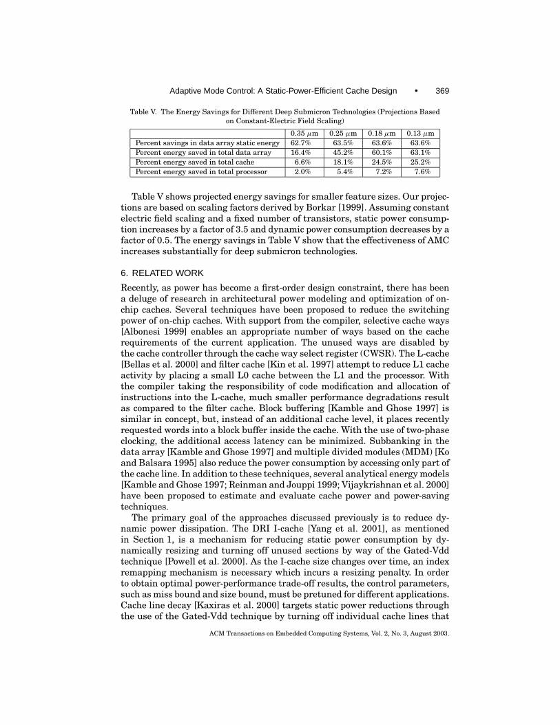
0.35 µm 0.25 µm 0.18 µm 0.13 µmPercent savings in data array static energy 62.7% 63.5% 63.6% 63.6%Percent energy saved in total data array 16.4% 45.2% 60.1% 63.1%Percent energy saved in total cache 6.6% 18.1% 24.5% 25.2%Percent energy saved in total processor 2.0% 5.4% 7.2% 7.6%
Table V shows projected energy savings for smaller feature sizes. Our projec-tions are based on scaling factors derived by Borkar [1999]. Assuming constantelectric field scaling and a fixed number of transistors, static power consump-tion increases by a factor of 3.5 and dynamic power consumption decreases by afactor of 0.5. The energy savings in Table V show that the effectiveness of AMCincreases substantially for deep submicron technologies.
6. RELATED WORK
Recently, as power has become a first-order design constraint, there has beena deluge of research in architectural power modeling and optimization of on-chip caches. Several techniques have been proposed to reduce the switchingpower of on-chip caches. With support from the compiler, selective cache ways[Albonesi 1999] enables an appropriate number of ways based on the cacherequirements of the current application. The unused ways are disabled bythe cache controller through the cache way select register (CWSR). The L-cache[Bellas et al. 2000] and filter cache [Kin et al. 1997] attempt to reduce L1 cacheactivity by placing a small L0 cache between the L1 and the processor. Withthe compiler taking the responsibility of code modification and allocation ofinstructions into the L-cache, much smaller performance degradations resultas compared to the filter cache. Block buffering [Kamble and Ghose 1997] issimilar in concept, but, instead of an additional cache level, it places recentlyrequested words into a block buffer inside the cache. With the use of two-phaseclocking, the additional access latency can be minimized. Subbanking in thedata array [Kamble and Ghose 1997] and multiple divided modules (MDM) [Koand Balsara 1995] also reduce the power consumption by accessing only part ofthe cache line. In addition to these techniques, several analytical energy models[Kamble and Ghose 1997; Reinman and Jouppi 1999; Vijaykrishnan et al. 2000]have been proposed to estimate and evaluate cache power and power-savingtechniques.
The primary goal of the approaches discussed previously is to reduce dy-namic power dissipation. The DRI I-cache [Yang et al. 2001], as mentionedin Section 1, is a mechanism for reducing static power consumption by dy-namically resizing and turning off unused sections by way of the Gated-Vddtechnique [Powell et al. 2000]. As the I-cache size changes over time, an indexremapping mechanism is necessary which incurs a resizing penalty. In orderto obtain optimal power-performance trade-off results, the control parameters,such as miss bound and size bound, must be pretuned for different applications.Cache line decay [Kaxiras et al. 2000] targets static power reductions throughthe use of the Gated-Vdd technique by turning off individual cache lines that
ACM Transactions on Embedded Computing Systems, Vol. 2, No. 3, August 2003.
370 • H. Zhou et al.
have not been accessed for some predefined interval—the decay interval. Sincethe decay interval is statically fixed, it cannot be updated dynamically to ac-commodate changes in cache requirements within and across applications.
Cache line decay was recently improved upon to make it more dynamic, with-out keeping the tag store active [Kaxiras et al. 2001]. This approach associatesa two-bit state machine with each cache line to gauge generational behavior.After a cache line is turned off, if the next access to the line occurs before 1
4 of theturn-off interval, the access is assumed to be from the same generation. This im-plies the cache line decayed too early. So the turn-off interval is increased. If thenext access to the decayed cache line occurs after 3
4 of the turn-off interval, theaccess is assumed to be from a different generation and the turn-off interval isdecreased. Using the terms in this paper, the first scenario is a predicted-sleepmiss and the second scenario is a predicted-ideal miss. Our implementationof this scheme, using their parameters [Kaxiras et al. 2001], shows that it isvery aggressive in turning off cache lines. Our results confirm their observationthat most live access intervals (i.e., the time between two accesses in the samegeneration) are short (less than 1k cycles) [Kaxiras et al. 2001]. Our measure-ments indicate that this trend holds for different cache configurations (e.g., forcompress, 97% and 94% of live access intervals are less than 1k cycles for 16 kBdirect-mapped and 64 kB 4-way D-caches, respectively). As a result, the turn-off interval gauged by their scheme is close to the lower bound of 1K cycles formany cache lines independent of cache configuration. For small caches, theirscheme produces similar turn-off ratios (66% compared to 60% for AMC, for16 kB direct-mapped) and similar performance degradation (5.5% compared to4.1% for AMC, for 16 kB direct mapped), with the advantage of also deacti-vating the tag store. For the 64 kB 4-way D-cache, their scheme results in amuch higher turn-off ratio (92% compared to 54% for AMC) at the cost of higherperformance degradation (15% compared to 1% for AMC). AMC, on the otherhand, has the ability to adjust the trade-off between static power savings andperformance degradation using the performance factor (PF).
7. CONCLUSIONS
We proposed a microarchitecture technique that dynamically adapts to evolv-ing cache requirements in order to conserve static power while maintainingperformance. The main contributions of this study are as follows.r The tag store is always kept active. This enables hypothetical performance
without sleep mode to be determined and used to control real performance.Dynamically monitoring hypothetical performance is an improvement oversetting arbitrary and static performance targets.r We proposed a control system that keeps the number of sleep misses within acertain factor of ideal misses. Using a relative factor instead of an arbitrary,absolute number is a key contribution.r We presented extensive results, including multiple I-cache and D-cacheconfigurations and sensitivity to AMC parameters. Previously unknown,interesting results emerged. Just one interesting example is that higherassociativity results in lower cache turn-off ratios. This was initially
ACM Transactions on Embedded Computing Systems, Vol. 2, No. 3, August 2003.
Adaptive Mode Control: A Static-Power-Efficient Cache Design • 371
counterintuitive, but the explanation is that associative caches utilize a fixedamount of space better than direct-mapped caches.r We demonstrated that AMC is overall a very effective means for improv-ing static-power efficiency in caches while maintaining good performance.Our overall results show that an average of 73% of I-cache lines and 54% ofD-cache lines can be turned off with only a 1.8% performance loss.r A comparison with “oracle,” which maximizes energy savings within the con-straint of zero performance degradation, reaffirms AMC’s effectiveness.r We showed that turning off some of the tag bits for sleep-mode lines actuallyreduces overall static power savings. Using fewer tag bits causes the numberof perceived sleep misses to increase, and AMC compensates by deactivat-ing fewer cache lines. We used a large line size, which means it is better tokeep the full tag active than sacrifice power savings in the data array. Theconclusion may change for smaller cache line sizes.r We performed a detailed energy analysis based on SPICE simulations, lay-out extractions, process parameters, and other information taken from theAlpha 21264 instruction cache. AMC energy overheads were included in theanalysis. The analysis calculated energy savings of 6.4% at the cache leveland 2.0% at the processor level. The savings are expected to be much higherin future deep submicron technologies.
ACKNOWLEDGMENTS
We want to thank the anonymous reviewers for their very useful suggestions.This research was supported by generous funding and equipment donationsfrom Compaq, Intel, and Ericsson, and by NSF CAREER grant CCR-0092832.
REFERENCES
ALBONESI, D. 1999. Selective cache ways: On-demand cache resource allocation. In Proceedingsof the 32nd Annual IEEE/ACM International Symposium on Microarchitecture (MICRO 32)(November), 248–259.
BELLAS, N., HAJJ, I., AND POLYCHROPOULOS, C. 1999. A detailed, transistor-level energy model forSRAM-based caches. In Proceedings of International Symposium on Circuits and Systems, vol. 6,198–201.
BELLAS, N., HAJJ, I., POLYCHROPOULOS, C, AND STAMOULIS, G. 2000. Architectural and compiler tech-niques for energy reduction in high-performance microprocessors. IEEE Transactions on VLSISystems 8, 3, 317–326.
BORKAR, S. 1999. Design challenges of technology scaling. IEEE Micro 19, 4 (July), 23–29.BURGER, D. AND AUSTIN, T. M. 1997. The Simplescalar Tool Set Version 2.0. Tech. Rep., Computer
Science Department, University of Wisconsin-Madison.BUTTS, J. A. AND SOHI, G. S. 2000. A static power model for architects. In Proceedings of
the 33rdAnnual IEEE/ACM International Symposium on Microarchitecture (MICRO 33)(December), 191–201.
GONZALEZ, R. AND HOROWITZ, M. 1996. Energy dissipation in general purpose microprocessors.IEEE Journal of Solid-State Circuits 31, 9, 1277–1284.
GWENNAP, L. 1996. Digital 21264 sets new standard. Microprocessor Report 10, 14 (October).KAMBLE, M. B. AND GHOSE, K. 1997. Analytical energy dissipation models for low power caches.
In Proceedings of the International Symposium on Low Power Electronics and Design (ISLPED)(August), 143–148.
ACM Transactions on Embedded Computing Systems, Vol. 2, No. 3, August 2003.
372 • H. Zhou et al.
KAXIRAS, S., HU, Z., AND MARTONOSI, M. 2001. Cache decay: Exploiting generational behavior toreduce cache leakage power. In Proceedings of 28th International Symposium On Computer Ar-chitecture (ISCA) (June), 240–251.
KAXIRAS, S., HU, Z., NARLIKAR, G., AND MCLELLAN, R. 2000. Cache-line decay: A mechanism to reducecache leakage power. IEEE Workshop on Power Aware Computer Systems (November).
KIN, J., GUPTA, M., AND MANGIONE-SMITH, W. 1997. The filter cache: An energy efficient memorystructure. In Proceedings of the 30th Annual IEEE/ACM International Symposium on Microar-chitecture (MICRO 30) (November), 184–193.
KO, U. AND BALSARA, P. T. 1995. Characterization and design of A low-power, high-performancecache architecture. In Proceedings of International Symposium on VLSI Technology, Systems,and Applications, 235–238.
KURODA, T., FUJITA, T., MITA, S., NAGAMATU, T., YOSHIOKA, S., SANO, F., NORISHIMA, M., MUROTA, M.,KAKO, M., KINUGAWA, M., KAKUMU, M., SAKURAI, T. 1996. A 0.9 V, 150 MHz 10 mW, 4 mm2, 2-Ddiscrete cosine transform core processor with variable threshold-voltage scheme. IEEE Journalof Solid-State Circuits 31, 1770–1779.
LEE, H.-H. S., TYSON, G. S., AND FARRENS, M. K. 2000. Eager writeback—A technique for improvingbandwidth utilization. In Proceedings of the 33rd Annual IEEE/ACM International Symposiumon Microarchitecture (MICRO 33) (December), 11–21.
MARGALA, M. 1999. Low power SRAM circuit design. In IEEE International Workshop on MemoryTechnology, Design, and Testing, 115–122.
MONTANARO, J., WITEK, R. T., ANNE, K., BLACK, A. J., COOPER, E. M., DOBBERPUHL, D. W., DONAHUE,P. M., ENO, J., HOEPPNER, G. W., KRUCKEMYER, D., LEE, T. H., LIN, P. C. M., MADDEN, L., MURRAY, D.,PEARCE, M. H., SANTHANAM, S., SNYDER, K. J., STEPHANY, R., AND THIERAUF, S. C. 1997. A 160-MHz,32-b, 0.5-W CMOS RISC microprocessor. Digital Technical Journal 9, 49–62.
NII, K., MAKINO, H., TUJIHASHI, Y., MORISHIMA, C., HAYAKAWA, Y., NUNOGAMI, H., ARAKAWA, T., AND
HAMANO, H. 1998. A Low power SRAM using auto-backgate-bontrolled MT—CMOS. In Pro-ceedings of the International Symposium on Low Power Electronics and Design (ISLPED), 293–298.
POWELL, M., YANG, S.-H., FALSAFI, B., ROY, K., AND VIJAYKUMAR, T. 2000. Gated-Vdd: A circuit tech-nique to reduce leakage in deep-submicron cache memories. In Proceedings of the InternationalSymposium on Low Power Electronics and Design (ISLPED), 90–95.
REINMAN, G. AND JOUPPI, N. 1999. An itegrated cache timing and power model. CACTI 2.0 Tech.Rep., COMPAQ Western Research Lab.
SHIGEMATSU, S., MUTOH, S., MATSUYA, Y., TANABE, Y., AND YAMADA, J. 1997. A 1-V high speed MTC-MOS circuit scheme for power-down application circuits. IEEE Journal of Solid-State Circuits32, 861–869.
VIJAYKRISHNAN, N., KANDEMIR, M., IRWIN, M. J., KIM, H. S., AND YE, W. 2000. Energy-Driven Inte-grated Hardware-Software Optimizations Using SimplePower. In Proceedings of 27th Interna-tional Symposium on Computer Architecture (ISCA) (June), 95–106.
YANG, S.-H., POWELL, M., FALSAFI, B., ROY, K. AND VIJAYKUMAR, T. 2001. An integrated cir-cuit/architecture approach to reducing leakage in deep-submicron high-performance I-caches.In Proceedings of the International Symposium on High Performance Computer Architecture(HPCA) (January), 147–157.
YE, Y., BORKAR, S., AND DE, V. 1998. A new technique for standby leakage reduction in high per-formance circuits. In IEEE Symposium on VLSI Circuits, 40–41.
ZHOU, H., TOBUREN, M., ROTENBERG, E., AND CONTE, T. M. 2000. AMC: A Low Leakage Power EfficientOn-chip Cache System Design. Tech. Rep., Department of Electrical and Computer Engineering,North Carolina State University.
Received February 2002; accepted July 2002
ACM Transactions on Embedded Computing Systems, Vol. 2, No. 3, August 2003.