Embed Size (px)
Citation preview

Adaptive Fuzzy Sliding Mode Control of Variable Speed Wind Turbine for Maximum Power Extraction
R.SARAVANAKUMAR, DEBASHISHA JENA
Department of Electrical Engineering National Institute of Technology Karnataka Surathkal
Mangalore INDIA
[email protected] [email protected] Abstract: - This paper deals with nonlinear control of variable speed wind turbine (VSWT), where the dynamics of the wind turbine (WT) is obtained from single mass model. The main objective of this work is to maximize the energy capture form the wind with reduced oscillation on the drive train. The generator torque is considered as the control input to the WT. In general the conventional control techniques such as Aerodynamic torque feed forward (ATF) and Indirect speed control (ISC) are unable to track the dynamic aspect of the WT. The nonlinear controllers such as nonlinear dynamic state feedback linearization with estimator (NDSFE) and nonlinear static state feedback linearization with estimator (NSSFE) are not robust with respect to model uncertainty and disturbances. To overcome the above drawbacks a Fuzzy Sliding mode controller (FSMC) with the estimation of effective wind speed is proposed. The Modified Newton Raphson (MNR) is used to estimate the effective wind speed from aero dynamic torque and rotor speed. The proposed controller is tested with different wind profiles with the presence of disturbances and model uncertainty. From the results the proposed controller was found to be suitable in maintaining a trade-off between the maximum energy capture and reduced transient on the drive train. Key-Words: - Variable speed Wind turbine, Fuzzy Sliding mode controller, Modified Newton Raphson, ATF and ISC. 1 Introduction Because of the power crises and environmental issues, renewable energy sources play a vital role in energy market. Among all renewable energy sources wind energy is one of the rapidly growing energy technology and its having own benefits such as pollution free, clean and environmental friendly. In recent years due to the advanced in drive technology and grid interconnection control the production of wind power is increased. Generally WT has two different types i.e. fixed speed WT (FSWT) and VSWT. By comparing these two technologies VSWT is more versatile then FSWT. The main advantages of VSWT over FSWT are the reduction in mechanical stress and power fluctuations [1-2]. Generally wind speed is classified in to two types i.e. below and above rated wind speed. Accordingly the WT control is classified into two types i.e. torque control and pitch control [3]. At below rated wind speed the main objective of the WT is maximize the wind energy capture from the wind by rotating the WT rotor at optimal rotor speed which is derived from effective wind speed. Direct measurement of effective wind speed is not
available because anemometer only measures the wind speed at a single point of the rotor swept area. At above rated speed the main objective of the WT is to control the pitch angles which are corresponding to the reference power. In literature some of the authors have discussed the control of WT with the assumption of measurement of effective wind speed. In [3] the design of WT control using linear parameter varying (LPV) gain scheduling technique is introduced. The above control technique is applied for both FSWT and VSWT. In [4] a fuzzy controller used to maximize the power capture, improve the efficiency, and the controller was found to be more robust to the wind gust and oscillatory torque. In [5] control algorithm i.e. fuzzy logic control (FLC) tracks the maximum power by controlling the WT rotor speed without estimation the effective wind speed. Several literatures have reported to estimate the effective wind with WT control. In [6] the rotor speed and aerodynamic torque are estimated by the input and state based estimation with the known pitch angle, the effective wind speed is calculated by the inversion of the static aerodynamic model. In [7-9]
WSEAS TRANSACTIONS on POWER SYSTEMS R. Saravanakumar, Debashisha Jena
E-ISSN: 2224-350X 281 Volume 9, 2014

Kalman filter (KF) is used to estimate rotor speed and aerodynamic torque and finally the effective wind speed is calculated using Newton Raphson. For the single mass model give in [7-8] and two mass model given in [9], nonlinear controllers such as NSSFE and NDSFE are used to control the WT at below rated wind speed. For both the controllers the wind speed is estimated using Newton Raphson. In [10] calculation of effective wind speed is achieved by the particle filter and FLC is used to control the WT at below rated wind speed. In [11-13] the SMC based controllers are applied to the WT without estimating the effective wind speed. Authors in [11-12] discussed higher order sliding mode control (HSMC) of WT at below and above rated speed and it were found that HSMC is more robust with respect to parameter uncertainty of the WT. In [13] conventional sliding mode controller (SMC) based control with adaptive sliding gain is used to control the WT where the sliding gain is varied by an adaptation algorithm. The objective of this work is to maximize the energy capture form the wind with reduced oscillation in drive train by using the proposed FSMC control. Modified Newton Rapshon (MNR) is used to estimate the effective wind speed. A comparison of WT efficiency, with respect to maximum power capture, reduced transient load on drive train, and robustness to disturbance and model uncertainty is done between SMC and FSMC control. It was found that FSMC is achieving the above objectives with robustness to disturbance of the controller and model uncertainty. The results are validated for different wind speed profile. 2 Wind Turbine A WT is a device which converts the kinetic energy of the wind in to electric energy. Simulation complexity of the WT purely depends on the type of control objectives. In case of WT modelling complex simulators are required to verify the dynamic response of multiple components and aerodynamic loading. Generally dynamic loads and interaction of large components are verified by the aero elastic simulator. For designing a WT controller, instead of going with complex simulator the design objective can be achieved by using simplified mathematical model. In this work WT model is described by the set of nonlinear ordinary differential equation with limited degree of freedom. This paper describes the control law for a simplified mathematical model with the objective of optimal power capture at below rated wind speed and reduced oscillation of the drive train. The proposed
controller is tested with different wind profiles in the presence of model uncertainty and disturbances. Generally VSWT system consists of the following components i.e. aerodynamics, drive trains, and generator are shown in Fig.1.
RotorAerodynamics
Drivetrains GeneratorWind
Speed
υ aT
rω
gT
gωeP
Fig.1 Schematic of WT.
Equation 1 gives the nonlinear expression for aerodynamic power capture by the rotor
32 ),(21 υβλρπ Pa CRP = (1)
Where R is the radius, ρ is the air density, rω is the rotor speed (rad/sec), CP is the power coefficient of the WT and υ is the wind speed (m/sec). From equation 1 aerodynamic power (Pa) is directly proportional to the cube of the wind speed. The power coefficient CP is the function of blade pitch angle ( β ) and tip speed ratio ( λ ) and is defined as ratio between linear tip speed and wind speed.
υωλ Rr= (2)
Generally wind speed is stochastic nature with respect to time. Because of this tip speed ratio gets affected which leads to the variation in power coefficient. The relationship between aerodynamic torque (Ta) and rotor speed with respect to aerodynamic power is given in equation 3.
raa TP ω= (3) 23 ),(
21 υβλρπ qa CRT = (4)
where qC is the torque coefficient given as
λβλβλ ),(),( P
qCC = (5)
Substituting equation (5) in equation (4) we get 23 ),(
21 υ
λβλρπ P
aCRT = (6)
In above equation the nonlinear term Cp can be approximated by the 5th order polynomial.
55
44
33
22
10
5
0
)( aaaaaaaCn
nnP λλλλλλλ +++++==∑
=
(7)
Table 1 Coefficients values
a0=0.1667 a3=-0.01617 a1=-0.2558 a4=0.00095
a2=0.115 a5=-2.05*10-5
WSEAS TRANSACTIONS on POWER SYSTEMS R. Saravanakumar, Debashisha Jena
E-ISSN: 2224-350X 282 Volume 9, 2014
0 2 4 6 8 10 12 140
0.1
0.2
0.3
0.4
0.5
Lamda
C p
Fig.2 Cp vs λ curve
Where a0 to a5 are the WT power coefficient. The values of approximated coefficients are given in Table 1.Fig.2 shows the Cp versus λ curve.
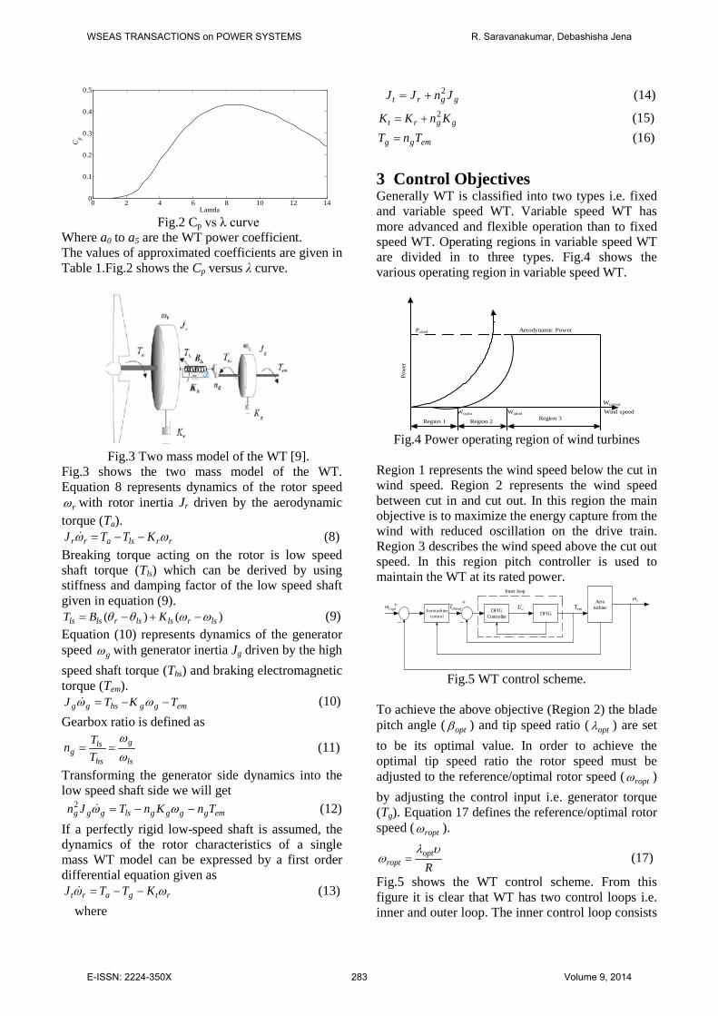
Fig.3 Two mass model of the WT [9].
Fig.3 shows the two mass model of the WT. Equation 8 represents dynamics of the rotor speed
rω with rotor inertia Jr driven by the aerodynamic torque (Ta).
rrlsarr KTTJ ωω −−= (8) Breaking torque acting on the rotor is low speed shaft torque (Tls) which can be derived by using stiffness and damping factor of the low speed shaft given in equation (9).
)()( lsrlslsrlsls KBT ωωθθ −+−= (9) Equation (10) represents dynamics of the generator speed gω with generator inertia Jg driven by the high speed shaft torque (Ths) and braking electromagnetic torque (Tem).
emgghsgg TKTJ −−= ωω (10) Gearbox ratio is defined as
ls
g
hs
lsg T
Tnωω
== (11)
Transforming the generator side dynamics into the low speed shaft side we will get emgggglsggg TnKnTJn −−= ωω2 (12) If a perfectly rigid low-speed shaft is assumed, the dynamics of the rotor characteristics of a single mass WT model can be expressed by a first order differential equation given as
rtgart KTTJ ωω −−= (13) where
ggrt JnJJ 2+= (14)
ggrt KnKK 2+= (15)
emgg TnT = (16)
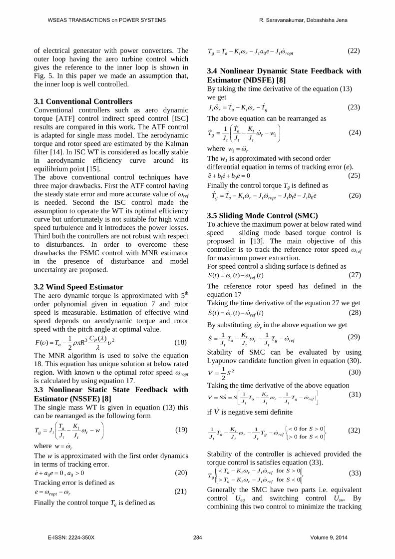
3 Control Objectives Generally WT is classified into two types i.e. fixed and variable speed WT. Variable speed WT has more advanced and flexible operation than to fixed speed WT. Operating regions in variable speed WT are divided in to three types. Fig.4 shows the various operating region in variable speed WT.
Powe
r
Aerodynamic Power
Region 1 Region 2 Region 3Wcutin
Wcutout
Wrated Wind speed
Prated
Fig.4 Power operating region of wind turbines
Region 1 represents the wind speed below the cut in wind speed. Region 2 represents the wind speed between cut in and cut out. In this region the main objective is to maximize the energy capture from the wind with reduced oscillation on the drive train. Region 3 describes the wind speed above the cut out speed. In this region pitch controller is used to maintain the WT at its rated power.
Aeroturbinecontrol
DFIGController DFIG
Aeroturbineoptrω refemT rU emT
rω+ +
− −
Inner loop
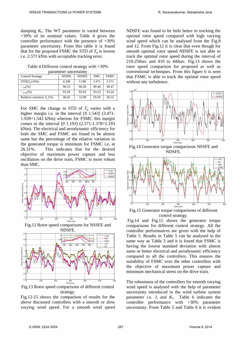
Fig.5 WT control scheme.
To achieve the above objective (Region 2) the blade pitch angle ( optβ ) and tip speed ratio ( optλ ) are set to be its optimal value. In order to achieve the optimal tip speed ratio the rotor speed must be adjusted to the reference/optimal rotor speed ( roptω ) by adjusting the control input i.e. generator torque (Tg). Equation 17 defines the reference/optimal rotor speed ( roptω ).
Ropt
roptυλ
ω = (17)
Fig.5 shows the WT control scheme. From this figure it is clear that WT has two control loops i.e. inner and outer loop. The inner control loop consists
WSEAS TRANSACTIONS on POWER SYSTEMS R. Saravanakumar, Debashisha Jena
E-ISSN: 2224-350X 283 Volume 9, 2014
of electrical generator with power converters. The outer loop having the aero turbine control which gives the reference to the inner loop is shown in Fig. 5. In this paper we made an assumption that, the inner loop is well controlled. 3.1 Conventional Controllers Conventional controllers such as aero dynamic torque [ATF] control indirect speed control [ISC] results are compared in this work. The ATF control is adapted for single mass model. The aerodynamic torque and rotor speed are estimated by the Kalman filter [14]. In ISC WT is considered as locally stable in aerodynamic efficiency curve around its equilibrium point [15]. The above conventional control techniques have three major drawbacks. First the ATF control having the steady state error and more accurate value of ωref is needed. Second the ISC control made the assumption to operate the WT its optimal efficiency curve but unfortunately is not suitable for high wind speed turbulence and it introduces the power losses. Third both the controllers are not robust with respect to disturbances. In order to overcome these drawbacks the FSMC control with MNR estimator in the presence of disturbance and model uncertainty are proposed. 3.2 Wind Speed Estimator The aero dynamic torque is approximated with 5th order polynomial given in equation 7 and rotor speed is measurable. Estimation of effective wind speed depends on aerodynamic torque and rotor speed with the pitch angle at optimal value.
23 )(21)( υ
λλ
ρπυ Pa
CRTF −= (18)
The MNR algorithm is used to solve the equation 18. This equation has unique solution at below rated region. With known υ the optimal rotor speed ωropt is calculated by using equation 17. 3.3 Nonlinear Static State Feedback with Estimator (NSSFE) [8] The single mass WT is given in equation (13) this can be rearranged as the following form
−−= w
JK
JTJT r
t
t
t
atg ω (19)
where rw ω= The w is approximated with the first order dynamics in terms of tracking error.
00 =+ eae , 00 >a (20) Tracking error is defined as
rropte ωω −= (21) Finally the control torque Tg is defined as
roptttrtag JeaJKTT ωω −−−= 0 (22) 3.4 Nonlinear Dynamic State Feedback with Estimator (NDSFE) [8] By taking the time derivative of the equation (13) we get
grtart TKTJ
−−= ωω (23) The above equation can be rearranged as
−−= 1
1 wJK
JT
JT r
t
t
t
a
tg ω
(24)
where rw ω=1 The w1 is approximated with second order differential equation in terms of tracking error (e).
001 =++ ebebe (25) Finally the control torque Tg is defined as ebJebJJKTT ttropttrtag 01 −−−−=
ωω (26) 3.5 Sliding Mode Control (SMC) To achieve the maximum power at below rated wind speed sliding mode based torque control is proposed in [13]. The main objective of this controller is to track the reference rotor speed ωref for maximum power extraction. For speed control a sliding surface is defined as
)()()( tttS refr ωω −= (27) The reference rotor speed has defined in the equation 17 Taking the time derivative of the equation 27 we get
)()()( tttS refr ωω
−= (28)
By substituting rω in the above equation we get
refgt
rt
ta
tT
JJKT
JS ωω
−−−=11 (29)
Stability of SMC can be evaluated by using Lyapunov candidate function given in equation (30).
2
21 SV = (30)
Taking the time derivative of the above equation
−−−== refg
tr
t
ta
tT
JJKT
JSSSV ωω
11 (31)
if V is negative semi definite
<>><
−−−0for00for011
SS
TJJ
KTJ refg
tr
t
ta
tωω
(32)
Stability of the controller is achieved provided the torque control is satisfies equation (33).
<−−>
>−−<
0for
0for
SJKT
SJKTT
reftrta
reftrtag ωω
ωω
(33)
Generally the SMC have two parts i.e. equivalent control Ueq and switching control Usw. By combining this two control to minimize the tracking
WSEAS TRANSACTIONS on POWER SYSTEMS R. Saravanakumar, Debashisha Jena
E-ISSN: 2224-350X 284 Volume 9, 2014

error which satisfies the stability of the controller we will get.
)()()( tUtUtU sweq += (34) Finally the torque control structure is given in equation 35
)(sign SkJJKTT treftrtag +−−= ωω (35) The major drawback in the signum function is it has the discontinued value between +1 and -1 because of this it introduces the chattering phenomenon. So the signum function is changed by a smooth function i.e. hyperbolic tangent (tanh) with boundary layer (ϕ ).
)(tanh ϕωω SkJJKTT treftrtag +−−= (36)
3.6 Proposed Fuzzy Sliding mode Control (FSMC) In order to avoid the chattering, the fixed boundary layer (ϕ ) in SMC has been replaced by the varying boundary layer (ϕ ) which can be achieved by the FSMC. Where boundary layer (ϕ ) is a function of
S and S [16].
Fixed boundary layer thickness may reduce the chattering but it introduces more tracking error in particular with servo systems. In this problem we need to avoid the tracking error and the control input i.e. Generator torque (Tg) to the WT should be as smooth as possible. Fuzzy Logic is used to improve the performance of the controller as well as the system. Triangular membership function is used both input and output. FL is used to automatically adjust the thickness of the boundary layer. The input to the fuzzy controller is sliding surface and derivative of the sliding surface and the output is boundary layer thickness. Table 2 gives the fuzzy rule base for the inputs and corresponding output. Fig.6 shows the 3D surface for input and output variables. From the conventional SMC the knowledge of the boundary layer is obtained. With this knowledge the fuzzy rules in table 2 are initially derived by trial and error method. After obtaining the rule base the simulation is carried out and it is tuned appropriately as per the control objectives. Finally the derived rule base is validated for +30% uncertainty and different mean wind speed conditions. From the results it is found that the rule base is optimal for achieving the given control objectives.
)(tanhFuzzy
treftrtagSkJJKTT ϕωω +−−= (37)
Table 2 Fuzzy rules .
, SS and fuzzyϕ NS NB Z PS PB NS Z NS PS NS NB NB NS PS NS NB Z Z NS NB NS PB NB PS PS PB Z NS NB PB PS PB NS PB NS
Fig.6 3D plot of
., SS and fuzzyϕ
4 Result and Discussion
0 100 200 300 400 500 6006.5
7
7.5
8
Time(sec)
Win
d Sp
eed
(m/s
ec)
Transient wind speedSmooth wind speed
440 450 460 4707
7.5
Fig.7 Test wind profile with mean of 7m/sec
0 100 200 300 400 500 600
2.5
2.6
2.7
2.8
2.9
3
3.1
3.2
3.3
Time(sec)
Rot
or sp
eed
(rad
/sec
)
wroptNSSFENDSFE
440 460 4802.6
2.8
3
Fig.8 Rotor speed comparisons for NSSFE and
NDSFE.
0 100 200 300 400 500 6002.5
2.6
2.7
2.8
2.9
3
3.1
3.2
3.3
Time (sec)
Rot
or sp
eed
(rad
/sec
)
wroptSMCFSMCATFISC440 450 460 470 480
2.6
2.8
3
Fig.9 Rotor speed comparisons of different control
strategy. Fig.7 shows the test wind profile of the WT with mean wind speed of 7 m/sec. Generally wind speed
WSEAS TRANSACTIONS on POWER SYSTEMS R. Saravanakumar, Debashisha Jena
E-ISSN: 2224-350X 285 Volume 9, 2014

consists of two component i.e. mean wind speed and turbulent component. From this figure it is clear that two different wind speeds are used with different turbulence intensity. Both the wind speeds are having 10 minutes wind data with the standard deviation (STD) of 0.25 m/sec and 0.19m/sec. Fig.8 shows the rotor speed comparison for NSSFE and NDSFE. From this figure it is evident that NSSFE is almost tracking the optimal rotor speed compared with NDSFE. NDSFE is not able to track the optimal rotor speed in the time interval of 200 to 250sec and 410 to 440sec which is due the sub-optimal error dynamics coefficient i.e. bo and b1 setting in the control law. Fig.9 shows the rotor speed comparison for proposed FSMC as well as conventional techniques. It is found that both the conventional controllers such as ATF and ISC are having more tracking error with respect to optimal rotor speed. In general ATF control, inherently having the steady state error because of the proportional control law and ISC introduces the power loss during the high wind speed transients. The proposed FSMC is almost tracking the optimal rotor speed. smoothly compared with SMC and all the conventional techniques.
0 100 200 300 400 500 6004
4.2
4.4
4.6
4.8
5
5.2
5.4
5.6 x 10⁴
Time(sec)
Gen
erat
or to
rque
(Nm
)
NSSFENDSFE
Fig.10 Generator torque comparisons NSSFE and
NDSFE.
0 100 200 300 400 500 6003.8
4
4.2
4.4
4.6
4.8
5
5.2
5.4 x 10⁴
Time (sec)
Gen
erat
or to
rque
(Nm
)
ATFISCSMCFSMC
Fig.11 Generator torque comparisons of different
control strategy.
Fig.10 shows the generator torque comparison for the nonlinear controllers NSSFE and NDSFE. From this figure it is clear that NSSFE having more torque variation than NDSFE. But Fig.8 shows that tracking error for rotor speed is less for NSSFE. As
tracking error is related to maximum power capture and variation in load torque is dependent on the transient load in drive train, therefore a trade-off has to be made between the tracking error and variation of generator torque. Fig.11 shows comparison of generator torque for FSMC and other conventional controllers. For better clarity of the control action all the controllers are evaluated with different objectives such as,
• Electrical and aero dynamic efficiency. • Control input is evaluated by its maximum
value and standard deviation (STD). • Control algorithm tested with added
disturbance and model uncertainty. As shown in Table 3 NSSFE is having the highest value of the generator torque (55.91 kNm) which ensures the maximum power capture among all other controllers. At the same time it is having more transient load on drive train because the STD of Tg is also having the highest value i.e. 2.753 kNm. According to the STD of Tg, FSMC is lowest compared to the all the controllers i.e. 1.387 kNm which indicate less transient load on drive train. As both the objectives cannot be achieved simultaneously a compromise has to be made between them. So for good control a trade-off is to be maintained between the maximum power capture and oscillation in drive train. Analysis of table 3 gives a complete comparison on the results obtained for different controllers which clears that FSMC having almost same electrical and aerodynamic efficiency (i.e. 91.12% and 93.24%) with the NSSFE (i.e. 91.16% and 93.29%) which is highest among all. But at the same time FSMC having lowest standard deviation of control input which ensures reduced transient load on drive train. Analysis of Table 3 also gives that FSMC is having better performance in terms of the efficiency and relative variation in generator torque, compared with its counterpart i.e. SMC.
Table 3 Different control strategy with high transient wind speed
Control Strategy
ATF ISC NSSFE NDSFE SMC FSMC
Max(Tg)kNm
53.23 52.07 55.91 53.58 51.92 51.31
STD(Tg) kNm
2.42 2.12 2.753 2.315 1.928 1.387
Ƞele(%) 89.43 89.37 91.16 90.93 91.10 91.12 Ƞaero(%) 91.6 91.56 93.29 93.07 93.23 93.24 Relative variation Tg (%)
30.41 25.30 32.08 23.43 17.25 14.83
In order to analyse the robustness of the controllers a parameter uncertainty is introduced in the WT system parameters i.e. turbine inertia Jt and turbine
WSEAS TRANSACTIONS on POWER SYSTEMS R. Saravanakumar, Debashisha Jena
E-ISSN: 2224-350X 286 Volume 9, 2014
damping Kt. The WT parameter is varied between +30% of its nominal values. Table 4 gives the controller performance with the presence of +30% parameter uncertainty. From this table it is found that for the proposed FSMC the STD of Tg is lowest i.e. 2.571 kNm with acceptable tracking error.
Table 4 Different control strategy with +30%
parameter uncertainty Control Strategy NSSFE NDSFE SMC FSMC STD(Tg) kNm 4.348 3.186 3.471 2.571 Ƞele(%) 90.53 90.28 90.46 90.47 Ƞaero(%) 93.29 93.03 93.23 93.24 Relative variation Tg (%) 48.42 32.98 29.36 26.31
For SMC the change in STD of Tg varies with a higher margin i.e. in the interval [0 1.543] (3.471-1.928=1.543 kNm) whereas for FSMC this margin comes in the interval [0 1.193] (2.571-1.378=1.193 kNm). The electrical and aerodynamic efficiency for both the SMC and FSMC are found to be almost same but the percentage of the relative variation in the generated torque is minimum for FSMC i.e, at 26.31%. This indicates that for the desired objective of maximum power capture and less oscillation on the drive train, FSMC is more robust than SMC.
0 100 200 300 400 500 6002.5
2.6
2.7
2.8
2.9
3
3.1
3.2
3.3
Time (sec)
Rot
or s
peed
(ra
d/se
c)
wroptNSSFENDSFE
450 460 470 480 490
2.72.82.9
Fig.12 Rotor speed comparisons for NSSFE and
NDSFE.
0 100 200 300 400 500 6002.5
2.6
2.7
2.8
2.9
3
3.1
3.2
3.3
Time (sec)
Rot
or s
peed
(rad
/sec
)
wroptSMCFSMCATFISC
440 450 460 470 480
2.8
3
Fig.13 Rotor speed comparisons of different control
strategy. Fig.12-15 shows the comparison of results for the above discussed controllers with a smooth or slow varying wind speed. For a smooth wind speed
NDSFE was found to be little better in tracking the optimal rotor speed compared with high varying wind speed which can be analysed from the Fig.8 and 12. From Fig.12 it is clear that even though for smooth optimal rotor speed NDSFE is not able to track the optimal rotor speed during the interval of 210-250sec and 410 to 440sec. Fig.13 shows the rotor speed comparison for proposed as well as conventional techniques. From this figure it is seen that FSMC is able to track the optimal rotor speed without any turbulence.
0 100 200 300 400 500 6004.2
4.4
4.6
4.8
5
5.2
5.4 x 10⁴
Time (sec)
Gen
erat
or to
rque
(Nm
)
NSSFENDSFE
Fig.14 Generator torque comparisons NSSFE and
NDSFE.
0 100 200 300 400 500 6004
4.2
4.4
4.6
4.8
5
5.2 x 10⁴
Time (sec)
Gen
erat
or to
rque
(Nm
)
ATFISCSMCFSMC
Fig.15 Generator torque comparisons of different
control strategy. Fig.14 and Fig.15 shows the generator torque comparisons for different control strategy. All the controller performances are given with the help of Table 5. Results in Table 5 can be analysed in the same way as Table 3 and it is found that FSMC is having the lowest standard deviation with almost same or better electrical and aerodynamic efficiency compared to all the controllers. This ensures the suitability of FSMC over the other controllers with the objective of maximum power capture and minimum mechanical stress on the drive train. The robustness of the controllers for smooth varying wind speed is analysed with the help of parameter uncertainty introduced in the wind turbine system parameter i.e. Jt and Kt. Table 6 indicates the controller performance with +30% parameter uncertainty. From Table 5 and Table 6 it is evident
WSEAS TRANSACTIONS on POWER SYSTEMS R. Saravanakumar, Debashisha Jena
E-ISSN: 2224-350X 287 Volume 9, 2014
that the change in STD of generator torque for FSMC with +30% uncertainty varies from 0 to 0.775 (2.037-1.262) whereas for SMC it varies from 0 to 1.088 (2.873-1.785). Nevertheless the variation range for STD of Tg for NSSFE is found to be lowest i.e. from 0 to 0.492 (2.495-2.003) but its other performances are not comparable with the proposed FSMC Table 5 Different control strategy with filtered wind
speed Control strategy
ATF ISC NSSFE NDSFE SMC FSMC
STD(Tg) kNm
2.226 2.048 2.003 1.785 1.77 1.262
Ƞele(%) 89.41 89.39 91.16 91.02 91.14 91.22 Ƞaero(%) 91.64 91.62 93.36 93.16 93.34 93.4 Relative
variation Tg (%)
26.27 23.87 21.88 17.36 16.18 13.19
Table 6 Different control strategy with +30%
parameter uncertainty Control Strategy NSSFE NDSFE SMC FSMC STD(Tg) kNm 2.911 2.495 2.873 2.037 Ƞele(%) 90.50 90.36 90.48 90.56 Ƞaero(%) 93.36 93.12 93.34 93.38 Relative variation (%) 31.18 25.18 24.76 19.01
The adaptability of the controller is analysed with different mean wind speed profiles at below rated wind speed. Table 7 and Table 8 shows the performance of all the controllers with a mean wind speed of 8 m/sec and 8.5 m/sec respectively. The results shown in Table 7 and 8 ensure the suitability of proposed FSMC among other conventional linear and nonlinear controllers that achieves the similar performance even though the mean wind speed changes. As predicted, the maximum generator torque increases with increase in mean wind speed which indicates the increase in power capture. Table 7 Different control strategy with mean wind
speed of 8 m/sec Control strategy
ATF ISC NSSFE NDSFE SMC FSMC
Max(Tg) kNm
67.18 67.12 70.19 66.83 67.04 67.94
STD(Tg) kNm
2.719 2.621 2.493 1.856 1.644 1.461
Ƞele(%) 89.42 89.39 91.42 91.16 91.45 91.54
Ƞaero(%) 91.66 91.65 93.38 93.14 93.38 93.49
Relative variation Tg (%)
30.71 28.31 22.61 13.47 15.65 13.82
Table 8 Different control strategy with mean wind speed of 8.5 m/sec
Control strategy ATF ISC NSSFE NDSFE SMC FSMC
Max(Tg) kNm 73.59 73.65 77.02 73.82 74.69 75.16
STD(Tg) kNm 2.785 2.742 2.418 1.777 1.424 1.337
Ƞele(%) 89.56 89.53 91.81 91.61 91.79 91.83
Ƞaero(%) 91.65 91.65 93.62 93.42 93.58 93.62
Relative variation Tg (%)
26.09 25.70 20.16 12.32 12.56 11.08
Table 9 Mean error in rotor speed for different
control strategy with different wind profile Mean Wind speed
NSSFE NDSFE SMC FSMC
7 m/sec 0.0630 0.0977 0.0714 0.0700 8 m/sec 0.0635 0.0973 0.0693 0.0674 8.5 m/sec 0.0592 0.0947 0.0678 0.0673
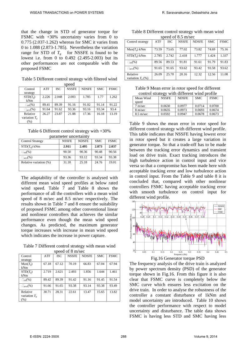
Table 9 shows the mean error in rotor speed for different control strategy with different wind profile. This table indicates that NSSFE having lowest error in rotor speed but it creates a large variation in generator torque. So that a trade-off has to be made between the tracking error dynamics and transient load on drive train. Exact tracking introduces the high turbulence action in control input and vice versa so that a compromise has been made here with acceptable tracking error and low turbulence action in control input. From the Table 9 and table 8 it is concluded that, compared with other nonlinear controllers FSMC having acceptable tracking error with smooth turbulence on control input for different wind profile.
0 0.05 0.1 0.15 0.2 0.25 0.3 0.35 0.4 0.45 0.520
40
60
80
100
120
140
Frequency (Hz)
Pow
er/F
requ
ency
(dB
/Hz)
NDSFESMCFSMC
0.28 0.29 0.3 0.31 0.32 0.33 0.34 0.35 0.36 0.37 0.38
40
60
Fig.16 Generator torque PSD
The frequency analysis of the drive train is analyzed by power spectrum density (PSD) of the generator torque shown in Fig.16. From this figure it is also clear that FSMC curve is completely below the SMC curve which ensures less excitation on the drive train. In order to analyse the robustness of the controller a constant disturbance of 1kNm and model uncertainty are introduced. Table 10 shows the controller performance with respect to model uncertainty and disturbance. The table data shows FSMC is having less STD and SMC having less
WSEAS TRANSACTIONS on POWER SYSTEMS R. Saravanakumar, Debashisha Jena
E-ISSN: 2224-350X 288 Volume 9, 2014
mean error in rotor speed. So Slightly higher power production can be achieved by SMC for below rated operation, at the cost of higher pulsations in the generated torque. A trade-off should be made between mean error with acceptable limit and STD of generated torque. Even though mean error in FSMC is comparatively more than SMC but according to the reduced oscillation in drive train FSMC is better than SMC.
Table 10 Controller disturbance with parameter uncertainty of different control strategy
Control strategy
NSSFE NDSFE SMC FSMC
STD(Tg) kNm
6.144 3.091 2.546 2.477
Mean (error) 0.1355 0.1001 0.0688 0.0976
5. Conclusions This paper deals with the objective of extracting maximum power generation with minimum mechanical stress on the drive train in VSWTs. Here a fuzzy sliding mode control is proposed to ensure the above objective and to impose an ideal feedback control solution despite of model disturbance and uncertainty in the model parameters. The proposed control was found to be more robust to parametric uncertainty in turbine parameters with a constant disturbance of 1kNm. The existing classical control techniques such as ATF, ISC, NSSFE and NDSFE are adapted in this paper. Existing controllers are having the drawbacks of steady state tracking error, significance power loss and complex control law. In this paper estimation of effective wind speed is done by the modified Newton Raphson and the proposed FSMC is used to extract the maximum power capture at below rated wind speed. Different wind speed profiles are tested for proposed as well as existing controllers, from these results it is concluded that, the proposed FSMC controller gives better efficiency and reduced oscillation in the drive train compared with existing controllers. Indeed, the fuzzy sliding-mode approach is used so as to produce less chattering in the generated torque control action. References: [1] P.W Carlin, S. Laxson, and E. B. Muljadi, The History and State of the Art of Variable- Speed Wind Turbine Technology, Wind Energy, Vol.6,No.2, 2003, pp. 129–159. [2] Q. Wang, L. Chang, and S. Member, An Intelligent Maximum Power Extraction Algorithm for Inverter-Based Variable Speed
Wind Turbine Systems, IEEE Transactions on Power Electronics, Vol.19,No.5, 2004, pp. 1242–1249. [3] FD Bianchi, H De Battista, RJ Mantz, Wind turbine control systems: principles, modelling and gain scheduling design, Springer Verlag, 2007. [4] M. G. Simoes, B. K. Bose, and R. J. Spiegel, Fuzzy logic based intelligent control of a variable Speed Cage Machine Wind Generation System, IEEE Transactions on Power Electronics, Vol.12,No.1, 1997, pp. 87–95. [5] A. M. Eltamaly and H. M. Farh, Maximum power extraction from wind energy system based on fuzzy logic control, Electr. Power Syst. Res., Vol.97, 2013, pp. 144–150. [6] K. Z. Østergaard, P. Brath, and J. Stoustrup, Estimation of effective wind speed, J. Phys. Conf. Ser., Vol.75, 2007. [7] B. Boukhezzar and H. Siguerdidjane, Nonlinear Control of Variable Speed Wind Turbines without wind speed measurement, IEEE Conference on Decision and Control, 2005, pp.3456–3461. [8] B. Boukhezzar, H. Siguerdidjane, and M. M. Hand, Nonlinear Control of Variable- Speed Wind Turbines for Generator Torque Limiting and Power Optimization, J. Sol. Energy Eng., Vol.128,No.4, 2006, pp. 516- 530. [9] B. Boukhezzar and H. Siguerdidjane, Nonlinear Control of a Variable-Speed Wind Turbine Using a Two-Mass Model, IEEE Trans. Energy Convers., Vol.26,No.1, 2011, pp. 149– 162. [10] I. Ćirić, Ž. Ćojbašić, et.al, Hybrid Fuzzy Control Strategies for Variable Speed Wind Turbines, Facta Universitatis, Vol.10, 2011, pp. 205–217. [11] B. Beltran, T. Ahmed-Ali, M.E.H.Benbouzid, Sliding mde power control of variable speed wind energy conversion system, IEEE Trans on Energy conversion, Vol.23,No.2, 2008, pp. 551-558. [12] B. Beltran, T.Ahmed-Ali, M.E.H. Benbouzid, Higher order sliding mode control of variable speed wind turbine control, IEEE Trans on Industrial Electronics, Vol.56,No.9, 2009, pp. 3314-3321. [13] A. Merabet, R. Beguenane, J. S. Thongam, and I. Hussein, Adaptive sliding mode speed control for wind turbine systems, IEEE Ind. Electron. Soc., 2011, pp. 2461–2466. [14] Vihriala, H., Perälä, R., Makila, P., and Soderlund, L., A Gearless Wind Power
WSEAS TRANSACTIONS on POWER SYSTEMS R. Saravanakumar, Debashisha Jena
E-ISSN: 2224-350X 289 Volume 9, 2014

Drive: Part 2: Performance of Control System, European Wind Energy Conference, 2011. [15] W. E. Leithead and B. Connor, Control of variable speed wind turbines: Design task, Int. Journal of Control, Vol.73,No.13, 2000, pp. 1189-1212. [16] P. Ben-Tzvi, S. Bai, Q. Zhou, and X. Huang, Fuzzy Sliding Mode Control of Rigid- Flexible Multibody Systems With Bounded Inputs, J. Dyn. Syst. Meas. Control, Vol.133,No.6, 2011.
WSEAS TRANSACTIONS on POWER SYSTEMS R. Saravanakumar, Debashisha Jena
E-ISSN: 2224-350X 290 Volume 9, 2014


![Fuzzy Gains-Scheduling of an Integral Sliding Mode …...implementation of an integral action on the controller based on sliding modes for a conventional helicopter. In [27], an adaptive](https://img.dokumen.tips/doc/110x75/5f085cdd7e708231d421a328/fuzzy-gains-scheduling-of-an-integral-sliding-mode-implementation-of-an-integral.jpg)


![Robust Fuzzy-Second Order Sliding Mode based …thesai.org/...Robust_Fuzzy_Second_Order_Sliding_Mode_based...Con… · Robust Fuzzy-Second Order Sliding Mode based ... [3]. Sliding-mode](https://img.dokumen.tips/doc/110x75/5b7a16407f8b9a483c8b5dce/robust-fuzzy-second-order-sliding-mode-based-robust-fuzzy-second-order-sliding.jpg)