Embed Size (px)
Citation preview

Adapted Monitoring Procedure for the thermal side of New Generation Solar Heating & Cooling Systems
IEA SHC TASK 53 | NEW GENERATION SOLAR COOLING & HEATING SYSTEMS (PV OR THERMALLY DRIVEN)

Adapted Monitoring Procedure for the thermal side of New Generation Solar Heating & Cooling Systems
Bettina Nocke1, Daniel Neyer2, Alexander Thür ², Karl Berger³ June 2018 Task 53 / Report C1-2, http://dx.doi.org/10.18777/ieashc-task53-2019-0009 1Institution AEE - Institute for Sustainable Technologies Address A-8200 Gleisdorf, Feldgasse 19 Phone +43 3112 5886221 e-mail [email protected] ²Institution University of Innsbruck, Institute for Construction and Material Sciences Address Technikerstrasse 19a, A-6020 Innsbruck Phone +43 512 507 63651 e-mail: [email protected] ³Institution AIT Austrian Institute of Technology GmbH Address Giefinggasse 2, A-1210 Vienna Phone +43 50550 6276 e-mail: [email protected] The contents of this report do not necessarily reflect the viewpoints or policies of the International Energy Agency (IEA) or its member countries, the IEA Solar Heating and Cooling Technology Collaboration Programme (SHC TCP) members or the participating researchers.

Contents Contents .......................................................................................................................................................... ii 1 Executive Summary .................................................................................................................................... 3 2 Data collection (Monitoring procedure) for solar thermal heating and cooling systems ...................................... 4
2.1 Previous works ....................................................................................................................................... 4 2.2 Thermal Cooling and Heating – recent work in Task 48 B7 ............................................................................ 5
2.2.1 General structure of the analysis, starting from IEA SHC Task 48 B7 .................................................... 5 2.2.2 Calculation of Performance Indicators in IEA SHC Task 48 B7 ............................................................ 7
3 Enlarged considerations for New Generation Solar Heating and Cooling Systems............................................. 9 4 Data Acquisition and Evaluation of data with Key Performance Figures ........................................................ 14
4.1 System boundaries of New Generation systems .......................................................................................... 14 4.1.1 Cooling energy ........................................................................................................................... 14 4.1.2 Heating energy ........................................................................................................................... 17 4.1.3 Domestic hot water production ...................................................................................................... 19
5 Measuring and instrumentation.................................................................................................................. 21 6 Bibliography ............................................................................................................................................. 22

1 Executive Summary
Activity 1 of Subtask C is dedicated to prepare the testing and the monitoring methodology to measure the performances of the selected demo projects for NG H&C-Systems.
A valorization of past and ongoing results from IEA SHC Task 38, 44 and 48 was done on how to properly monitor these systems, in order to achieve reliable indicators and significant information on the performance as well as primary energy savings and reduction of greenhouse gases, plus finally also on economic criteria.
In Task 48 Subtask C4 the most important measurement points and the way to collect the measurement data for demo projects in the solar cooling framework have been defined or updated from previous works and are very precisely described in the Final report “Measurement and Verification Procedures” (Deliverable M-C4.3 Task IEA SHC 48) [1] ., Even if the quantity of considered energy flows in Task 53 is significantly enlarged, the practical procedure is valid for a central part of the plants considered in Task 53, and the most important specific references will be given in the following chapters. New issues due to the superseded norm EN 1434-1 (heat meters) are considered.
Specific measurement issues for the photovoltaic systems are discussed in Deliverable D–C1.1 “Monitoring Procedure for Field Test & Demo Systems with Compression Heat Pumps Driven by Photovoltaic Solar Energy” by Universidad Miguel Hernández de Elche (P. V. Quiles and F. A. Valero), where this type of technology is evaluated by means of an example for a HVAC system in the range of 3 kW.
For the calculation of Key Performance indicators from the monitored data, the approach used in the more recent Subtask B7 of Task 48 was chosen. The tool developed in this framework “Collection of criteria to quantify the quality and cost competitiveness for solar cooling systems” (D. Neyer et al.), which enables technical and economic performance assessment for large solar cooling systems, has been adapted and extended for the use in this Subtask.
Nomenclature
Subscripts C Cooling NRE Non-renewable DC District Cooling el Electrical SH Space heating equ Equivalent DH District Heating sys Overall system (C & DHW & SH) DHW Domestic hot water
Nomenclature PERNRE Primary Energy Ratio (-) ACM Absorption chiller, fsav_NRE Fractional savings (-) AHP Absorption heat pump SPFequ Seasonal Performance Factor (-) VCC Vapour compression chiller SEER Seasonal Energy Efficient Ratio CT Cooling tower Primary Energy Factor
(kWh/kWhPE) HS Hot storage
CS Cold storage BS Battery storage EC Energy Carrier

2 Data collection (Monitoring procedure) for solar thermal heating and cooling systems
2.1 Previous works
In the activities of previous working groups which dealt with solar thermal cooling systems (IEA Tasks 38 and 48) as well as IEA Task 44 “Solar and Heat Pump Systems” different but similar approaches for the visualization and the appropriate evaluation of solar (thermal) systems, as shown in Figure 1 and Figure 2 were used:
Figure 1: left: Reference solar heating and cooling system including the single energy fluxes (SHC Max System) and a conventional HC system [Task IEA SCHC 38, Napolitano et al. 2010]; right: System representation of a “collective” solar air-conditioning/heating/ domestic hotwater system used in MeGaPICS and IEA Task 48 C4
[Boudéhenn et al. 2013]
Figure 2 left: example of visualisation of a Solar Heat Pump System [Task IEA 44- HPP-Annex 38, Malencovic et al. 2012]; right: Energy Flow Chart for a complex solar + HP system [Task IEA 48 B7, Neyer et al et al. 2015]
In the present Subtask, the last concept (Task 48 B7) with a sink/source-approach is used and further developed for calculation (by means of an appropriate calculation tool) of Key Performance Figures. On the other hand, for the data acquisition and monitoring (except for the PV-plant) the final document of Task 48 C4 will be the starting point, where all requirements for data collection of solar cooling systems are precisely investigated and described.
2.2 Thermal Cooling and Heating – recent work in Task 48 B7
Also, if the first practical step of the validation of a technical system is the positioning of measurement devices, it’s important to stabilize before the content of information and analyses to achieve by monitoring. For this reason, the main components, energy fluxes and interesting performance figures, as well as the “clustering” of the heating & cooling system in system boundaries, should be presented first.
As described in Deliverable B7 – Collection of criteria to quantify the quality and cost competitiveness for solar cooling systems – march 2015 (by UIBK, EURAC, CSIRO, ASiC), a lot of work has done in Task 48 to facilitate the valorization and comparison of solar thermal cooling systems in terms of performance, primary energy savings and costs. The starting point for prospective monitoring procedures which include solar electric heating and cooling systems was to survey available valorization models (Task 38, Task 44, SEPEMO).
The operated method will be here shortly described because it is the base for the evaluation tool used in Task 53.
2.2.1 General structure of the analysis, starting from IEA SHC Task 48 B7
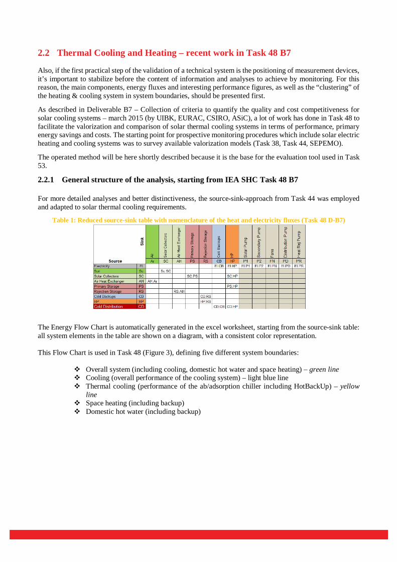
For more detailed analyses and better distinctiveness, the source-sink-approach from Task 44 was employed and adapted to solar thermal cooling requirements.
Table 1: Reduced source-sink table with nomenclature of the heat and electricity fluxes (Task 48 D-B7)
The Energy Flow Chart is automatically generated in the excel worksheet, starting from the source-sink table: all system elements in the table are shown on a diagram, with a consistent color representation. This Flow Chart is used in Task 48 (Figure 3), defining five different system boundaries:
Overall system (including cooling, domestic hot water and space heating) – green line Cooling (overall performance of the cooling system) – light blue line Thermal cooling (performance of the ab/adsorption chiller including HotBackUp) – yellow
line Space heating (including backup) Domestic hot water (including backup)

Figure 3: System boundaries and selected energy flows for calculation of e.g. the Seasonal Performance Factor of a SHC-system (Task 48 D-B7)
Energy flows are partioned in
Distributed energy (Cold distribution, Heat distribution, DHW distribution) Main components and sources (Solar collector, Hot BackUp,. Primary/Secondary Storage etc.) Losses at storages
• Percentage usage of Solar Energy and of the Hot Back Up for Primary storage or directly for Cold production/Heat pump, Heat and DHW distribution are defined.
Further partitions of energy fluxes of Primary Storage, Secondary (Cold-)Storage and Cold distribution have to be calculated.

2.2.2 Calculation of Performance Indicators in IEA SHC Task 48 B7
On component level, the main performance figures are defined and intended as follows [6]:
COP (Coefficient Of Performance) unit effectiveness at nominal rated conditions under steady-state operation, for heating applications only
EER (Energy Efficiency Ratio) same like COP but for cooling applications SCOP (Seasonal Coefficient Of Performance) assessment of the unit performance under defined, time
dependent rated conditions over a certain period of time SEER (Seasonal Energy Efficiency Ratio) same like SCOP but for cooling applications SPF (Seasonal Performance Factor) for the assessment of the (sub-)system performance including all
auxiliary components under defined, time dependent rating conditions over a certain period of time (including standby conditions).
For evaluating the energetic and environmental performance of the system, following performance indicators are defined:
Seasonal Performance Factor (SPFsys) Primary Energy Ratio (PER) Fractional savings (f_sav) Equivalent Seasonal Performance Factor (SPFequ)
2.2.2.1 Seasonal Performance Factor SPF
The SPF indicates the relation between useful energy and final energy and is defined for thermal and electrical inputs separately (necessary for thermal cooling processes where we have both types of input): The thermal SPF (relevant for thermal COOLING) is defined
푢푠푒푓푢푙 푐표푙푑ℎ푒푎푡 푓푟표푚 푠표푙푎푟 푐표푙푙푒푐푡표푟푠 푓표푟 푐표표푙푖푛푔 + ℎ푒푎푡 푓푟표푚 ℎ표푡 푏푎푐푘 푢푝 푓표푟 푐표표푙푖푛푔
The electrical SPF :
The electrical SPF is analyzed separately in Task 48 for the 5 different system boundaries Whole System, Cooling, Thermal Cooling, Heating and Domestic Hot Water.
2.2.2.2 Primary Energy Ratio (PER)
The PER is defined as the ratio of the useful energy output (ΣQi,out) to the primary energy input (Wel,i,in and Qi,in converted into Primary Energy) to the system boundary
푃퐸푅 =∑ ,
∑ , , , (51) D B7 Task 48
The PER can be
“overall” (i.e. comprising all types of Primary Energy) or “non-renewable only” (PERNRE) – in this framework always the last one is considered

substituted with emission factors (e.g. expressed in kgCO2,equ per kWh energy) or energy price (e.g. expressed in monetary unit per kWh energy)
Agreed conversion factors (ε) for Primary Energy and CO2-Emissions and values for efficiency factors for compression chillers, natural gas and pellets boilers (η) were already stabilized in Task 38 and Task 48, and are updated for Task 53 [8].
2.2.2.3 Fractional savings (f_sav)
are calculated to compare the renewable SHC system with a reference (might also be another renewable system).
푓 . . = 1 − .
. (16) D B7 Task 48
The formula is applicable for all subsystems in the stabilized boundaries.
2.2.2.4 Equivalent Seasonal Performance Factor (SPFequ)
This indicator can be used to compare the investigated solar heating and cooling system with a reference vapour compression chiller or a reversible heat pump based on the electrical seasonal performance factors SPFel_i and SPFref respectively. The SPFequ can be calculated following the unit conversion
= = , (71) D B7 Task 48
SPF . = , (76) D B7 Task 48 Same SPFequ’s indicates finally an equal primary demand of different systems.

3 Enlarged considerations for New Generation Solar Heating and Cooling Systems
The aim in this activity was to adapt the evaluation tool developed for Task 48 for the multitude of system configurations under the new heading of SHC. (A detailed description of the additional components considered in New Generation (NG) systems and of the new technical and economic assessment tool is given in the manual [9]).
So-called New Generation SHC-Systems embrace thermal and electrical Heating and Cooling if solar electricity or solar electricity and solar thermal energy production is included. For this reason, a wider range of components has to be taken into consideration.
Heating Sources may be a (reversible) heating pump or a boiler with fossil or renewable fuel), but also a CHP or an electrical heating element. The Cold Sources can be represented by a thermal or an electrical cooling device. Further electrical heating elements for SH & DHW are included.
Several heating and cooling sources can be chosen within the tool (Erreur ! Source du renvoi introuvable.). Any combination of these components is possible (bivalent/hybrid operation). Only exception is that just one solar thermal and one PV panel, as well as two heating- and cooling sources and two cooling towers are combined. For storage systems two sizes per storage class can be implemented. Within the calculation they are just considered separately for the economic cost determination. (A secondary hot water tank (for DHW) is assigned to the distribution part and therefore not listed here.
Table 2: Components in NG Heating & Cooling Systems
Solar thermal SC Flat plate collector Vacuum tube collector
Photovoltaic PV Photovoltaic (PV) Heating H1/H2 Natural gas boiler
Pellets boiler Heat pump (HP) (reversible / non-reversible) Natural gas absorption heat pump (AHP) (reversible / non-reversible) CHP unit Condensing boiler District heating
Cooling C1/C2 Air- or water-cooled vapor compression chiller (VCC)Single effect (SE) absorption chiller (ACM) Double effect (DE) ACM Adsorption chiller District cooling
Cooling tower CT Storage HS
CS BS
Hot storage (HS) Cold storage (CS) Battery storage (BS)
The Maximum scheme for Electrical and Thermal Solar Heating and Cooling Systems was supplemented by new components, and it’s now a little bit more complex. So also, the list of energy fluxes has been extended.
Figure 4 shows the new maximal scheme for NG SHC Systems. All possible sources, sinks and components and all corresponding energy flows are represented which could be necessary to be monitored, to calculate the technical key figures. Also, water consumption for direct evaporative cooling is included.

Figure 4: Maximal Scheme of energy flows in NG SHC-systems (including distribution)
Monitoring data to fill in the tool have always to be collected and elaborated in the context of the chosen system boundary (explained more in paragraph 4.1). Renewable sources / sinks (light green) are sun (Su), air, water, ground and waste heat. The last four usually are used with heat exchangers (HX). Solar energy can be converted by a solar thermal collector or a photovoltaic panel (PV). To run the whole plant electricity from the grid and energy carrier for the hot backup is necessary. Red/blue arrows refer to hot/cold thermal energy. Grey arrows mark electrical energy. The consumers are Domestic Hot Water (DHW or Water Distribution WD), Space Heating (SH), District Heating DH, Cooling Distribution (CD) and District Cooling (DC) as well as domestic electricity (DE).
For this multitude of components, also the number of energy flows to measure is correspondingly enlarged. The previous nomenclature as e.g. from Task 48 C4 is not more sufficient. A detailed description of all energy flows (summarized for bivalent options) can be found in Table 3.
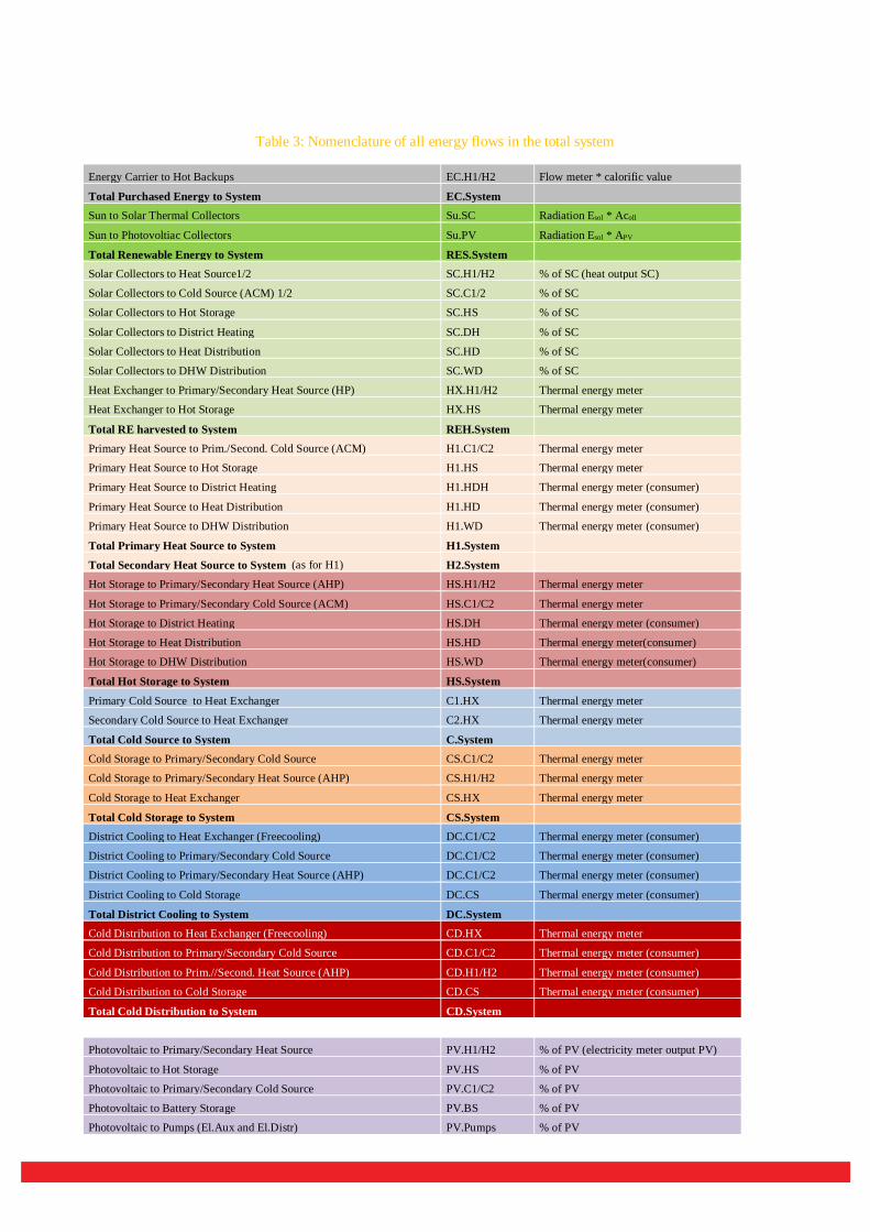
Table 3: Nomenclature of all energy flows in the total system
Energy Carrier to Hot Backups EC.H1/H2 Flow meter * calorific value
Total Purchased Energy to System EC.System Sun to Solar Thermal Collectors Su.SC Radiation Esol * Acoll
Sun to Photovoltiac Collectors Su.PV Radiation Esol * APV
Total Renewable Energy to System RES.System Solar Collectors to Heat Source1/2 SC.H1/H2 % of SC (heat output SC)
Solar Collectors to Cold Source (ACM) 1/2 SC.C1/2 % of SC
Solar Collectors to Hot Storage SC.HS % of SC
Solar Collectors to District Heating SC.DH % of SC
Solar Collectors to Heat Distribution SC.HD % of SC
Solar Collectors to DHW Distribution SC.WD % of SC
Heat Exchanger to Primary/Secondary Heat Source (HP) HX.H1/H2 Thermal energy meter
Heat Exchanger to Hot Storage HX.HS Thermal energy meter
Total RE harvested to System REH.System Primary Heat Source to Prim./Second. Cold Source (ACM) H1.C1/C2 Thermal energy meter
Primary Heat Source to Hot Storage H1.HS Thermal energy meter
Primary Heat Source to District Heating H1.HDH Thermal energy meter (consumer)
Primary Heat Source to Heat Distribution H1.HD Thermal energy meter (consumer)
Primary Heat Source to DHW Distribution H1.WD Thermal energy meter (consumer)
Total Primary Heat Source to System H1.System
Total Secondary Heat Source to System (as for H1) H2.System Hot Storage to Primary/Secondary Heat Source (AHP) HS.H1/H2 Thermal energy meter
Hot Storage to Primary/Secondary Cold Source (ACM) HS.C1/C2 Thermal energy meter
Hot Storage to District Heating HS.DH Thermal energy meter (consumer)
Hot Storage to Heat Distribution HS.HD Thermal energy meter(consumer)
Hot Storage to DHW Distribution HS.WD Thermal energy meter(consumer)
Total Hot Storage to System HS.System
Primary Cold Source to Heat Exchanger C1.HX Thermal energy meter
Secondary Cold Source to Heat Exchanger C2.HX Thermal energy meter
Total Cold Source to System C.System Cold Storage to Primary/Secondary Cold Source CS.C1/C2 Thermal energy meter
Cold Storage to Primary/Secondary Heat Source (AHP) CS.H1/H2 Thermal energy meter
Cold Storage to Heat Exchanger CS.HX Thermal energy meter
Total Cold Storage to System CS.System District Cooling to Heat Exchanger (Freecooling) DC.C1/C2 Thermal energy meter (consumer)
District Cooling to Primary/Secondary Cold Source DC.C1/C2 Thermal energy meter (consumer)
District Cooling to Primary/Secondary Heat Source (AHP) DC.C1/C2 Thermal energy meter (consumer)
District Cooling to Cold Storage DC.CS Thermal energy meter (consumer)
Total District Cooling to System DC.System Cold Distribution to Heat Exchanger (Freecooling) CD.HX Thermal energy meter
Cold Distribution to Primary/Secondary Cold Source CD.C1/C2 Thermal energy meter (consumer)
Cold Distribution to Prim.//Second. Heat Source (AHP) CD.H1/H2 Thermal energy meter (consumer)
Cold Distribution to Cold Storage CD.CS Thermal energy meter (consumer)
Total Cold Distribution to System CD.System
Photovoltaic to Primary/Secondary Heat Source PV.H1/H2 % of PV (electricity meter output PV)
Photovoltaic to Hot Storage PV.HS % of PV
Photovoltaic to Primary/Secondary Cold Source PV.C1/C2 % of PV
Photovoltaic to Battery Storage PV.BS % of PV
Photovoltaic to Pumps (El.Aux and El.Distr) PV.Pumps % of PV

Photovoltaic to Domestic Electricity PV.DE % of PV
Total Photovoltaic to System PV.sys Battery Storage to Switch Board Electricity BS.El Electricity meter Grid to Switch Board Electricity GD.El Electricity meter (El.Supplier)
Total Electricity to Switch Board El.In.System Switch Board Electricity to Grid El.GD Electricity meter (El.Supplier)
Total Switch Board to Grid El.GD.System Switch Board Electricity to Primary//Secondary Heat Source El.H1/H2 Electricity meter
Switch Board Electricity to Heat Storage (el. Heating Element) El.HS Electricity meter
Switch Board Electricity to Primary/Secondary Cold Source El.C1/C2 Electricity meter
Total Switch Board to System El.Comp.Syst. Switch Board Electricity to Solar Pump El.SP Electricity meter
Switch Board Electricity to H1/H2 Hot Temp. Pump El.HH1/2 Electricity meter
Switch Board Electricity to H1/H2 Medium Temp. Pump El.MH1/2 Electricity meter
Switch Board Electricity to H1/H2 Low Temp. Pump El.LH1/2 Electricity meter
Switch Board Electricity to C1/C2 Hot Temp. Pump El.HC1/2 Electricity meter
Switch Board Electricity to C1/C2 Medium Temp. Pump El.MC1/2 Electricity meter
Switch Board Electricity to C1/C2 Low Temp. Pump El.LC1/2 Electricity meter
Switch Board Electricity to Heat Exchange for Cooling (incl. MT) El.CX Electricity meter
Switch Board Electricity to Heat Exchange for Heating El.HX Electricity meter
Total Switch Board to Auxiliaries El.Aux.System Switch Board Electricity to Cold Distr. Pump El.CD Electricity meter
Switch Board Electricity to DHW Distr. Pump El.WD Electricity meter
Switch Board Electricity to Heat Distr. Pump El.HD Electricity meter
Switch Board Electricity to District Cooling El.DC Electricity meter
Switch Board Electricity to District Heating El.DH Electricity meter
Total Switch Board to Distribution Pumps El.Distr.System Switch Board Electricity to Domestic Electricity El.DE Electricity meter
Total Switch Board to Domestic Electricity El.DE.System
The useful energy flows on the whole system level are now:
Cold distribution (CD) of total system:
푄 . = 푄 . + 푄 . + 푄 . + 푄 . + 푄 . + 푄 . Eq. 1.1
Heat distribution (HD) of total system :
푄 . = 푄 . + 푄 . + 푄 . + 푄 . Eq. 1.2
Domestic hot water distribution (WD) of total system :
푄 . = 푄 . + 푄 . + 푄 . + 푄 . Eq. 1.3
District cooling (DC) of total system :
푄 . = 푄 . + 푄 . + 푄 . Eq. 1.4
District heating (DH) of total system :
푄 . = 푄 . + 푄 . + 푄 . + 푄 . Eq. 1.5
Total distributed energy :
푄 = 푄 . + 푄 . + 푄 . + 푄 . + 푄 . Eq. 1.6

Detailed formulas are given in the description of the Tool [9].
With this approach it’s not more necessary to define a “reference system” separately, because all energy production options are considered. The reference i.e. the system which the NG system is to compare, means in this context or a Solar Fraction of 0. If the system to analyze is an electrical or hybrid cooling system, the “reference” could be also a thermal driven Cooling system. The reference is always included in the scheme.
Electrical consumption here is not distinct between PV-produced or delivered from the grid. This will be defined by the electrical Solar Fraction, i.e. the photovoltaic contribution to Heating/Cooling or DHW production, as it is usually calculated for the solar thermal contribution.

4 Data Acquisition and Evaluation of data with Key Performance Figures
The main aim of the monitoring procedure is the verification of the functionality and performance of the Solar Heating & Cooling plant. As just mentioned in this regard, “it is desirable to have a more specific and targeted guide for solar cooling in order to simplify procedures, improve confidence in results and to assist M&V implementation with more detailed guidance”. [1] Now in Task 53 these guidelines were to be checked for their validity for “New Generation Systems”, and to be updated/enlarged where necessary. -
The following chapter gives an overview, which data of energy flows have to be measured and mapped for the respective system boundaries, in order to calculate technical and economic Key Figures by means of the calculation tool.
4.1 System boundaries of New Generation systems
In the maximal scheme in Figure 4, main system boundaries are marked with dashed lines:
System: sys (green) Cooling: C / Cooling Distribution: CD or District Cooling: DC (blue) Domestic Hot Water: DHW and Space Heating: SH or District Heating: DH (red)
(Data related to DHW production certainly can be measured and analyzed separately, but the components and energy flows are quit the same as for Space Heating.)
The above-mentioned KPI’s SPF, PER and fsave will be calculated for the particular applications by means of the tool, and formulas and details are given in the tool description [8]. Furthermore, the solar thermal fraction (SF or %SC), solar electrical usage (%PV) and the self-consumption of solar electricity would be interesting.
%푺푪 = 푸푺푪푸푺푪 푸푯풐풕 푩풂풄풌푼풑
Eq. 2
The “Electrical Solar Fraction” or “usage of solar electricity” in general is described by
%푷푽 = 푷푽.푬푳푷푽.푬푳 푮푫.푬푳
Eq. 3
and will be apportioned equally between the consuming components.
It is not necessary (only if desired to know it) to specify if electrical energy is used as auxiliary energy for pumps etc., or for direct transformation in thermal energy. Direct Heating by PV e.g. may be represented by EL.H1/H2 and H1/2.HD (without thermal losses).
4.1.1 Cooling energy
The components and energy flows related to a Cooling system (e.g. with air as re-cooling source) are highlighted in Figure 5. (Hot storage and Hot backup in summer operation can be partially used also for DHW-production).
Cooling energy can be produced by a thermal way (ACM), assisted by electrical cold or hot back up, or directly with an electrical heat pump. The choice between monovalent or bivalent/hybrid systems with 2 cooling devices is possible. The reference system is included in the same scheme and can be chosen depending on the real case to investigate.
In Table 4 the maximum possible energy flows involved in a NG Solar Cooling system are presented. It can be used as a check-list for planning the disposition of measuring equipment for the real existing energy content

in the cooling system. The collocation of thermal energy meters should allow the correct attribution of losses (near to the consumer and to source output/storage output).
Figure 5: Energy flows for Cooling operation with air-recooling
Table 4: Possible Energy flows to monitor for Cooling system
Energy Carrier to Hot Backups EC.H1/H2 Flow meter * calorific value
Total Purchased Energy to System EC.System Sun to Solar Thermal Collectors Su.SC Radiation Esol * Acoll
Sun to Photovoltiac Collectors Su.PV Radiation Esol * APV
Total Renewable Energy to System RES.System Solar Collectors to Heat Source1/2 SC.H1/H2 % of SC (heat output SC)
Solar Collectors to Cold Source (ACM) 1/2 SC.C1/2 % of SC
Solar Collectors to Hot Storage SC.HS % of SC
Heat Exchanger to Primary/Secondary Heat Source (HP) HX.H1/H2 Thermal energy meter
Heat Exchanger to Hot Storage HX.HS Thermal energy meter
Total RE harvested to System REH.System Primary Heat Source to Primary/Secondary Cold Source (ACM) H1.C1/C2 Thermal energy meter
Primary Heat Source to Hot Storage H1.HS Thermal energy meter
Total Primary Heat Source to System H1.System
Total Secondary Heat Source to System (as H1) H2.System Hot Storage to Primary/Secondary Heat Source (AHP) HS.H1/H2 Thermal energy meter
Hot Storage to Primary/Secondary Cold Source (ACM) HS.C1/C2 Thermal energy meter
Total Hot Storage to System HS.System Primary Cold Source to Heat Exchanger C1.HX Thermal energy meter
Secondary Cold Source to Heat Exchanger C2.HX Thermal energy meter
Total Cold Source to System C.System Cold Storage to Primary/Secondary Cold Source CS.C1/C2 Thermal energy meter
Cold Storage to Primary/Secondary Heat Source (AHP) CS.H1/H2 Thermal energy meter
Cold Storage to Heat Exchanger CS.HX Thermal energy meter
Total Cold Storage to System CS.System

District Cooling to Heat Exchanger (Freecooling) DC.C1/C2 Thermal energy meter (consumer)
District Cooling to Primary/Secondary Cold Source DC.C1/C2 Thermal energy meter (consumer)
District Cooling to Primary/Secondary Heat Source (AHP) DC.C1/C2 Thermal energy meter (consumer)
District Cooling to Cold Storage DC.CS Thermal energy meter (consumer)
Total District Cooling to System DC.System Cold Distribution to Heat Exchanger (Freecooling) CD.HX Thermal energy meter (consumer)
Cold Distribution to Primary/Secondary Cold Source CD.C1/C2 Thermal energy meter (consumer)
Cold Distribution to Primary//Secondary Heat Source (AHP) CD.H1/H2 Thermal energy meter (consumer)
Cold Distribution to Cold Storage CD.CS Thermal energy meter (consumer)
Total Cold Distribution to System CD.System Photovoltaic to Primary/Secondary Heat Source PV.H1/H2 % of PV (electricity meter output PV)
Photovoltaic to Hot Storage PV.HS % of PV
Photovoltaic to Primary/Secondary Cold Source PV.C1/C2 % of PV
Photovoltaic to Battery Storage PV.BS % of PV
Photovoltaic to Pumps (El.Aux and El.Distr) PV.Pumps % of PV
Total Photovoltaic to System PV.sys Battery Storage to Switch Board Electricity BS.El Electricity meter Grid to Switch Board Electricity GD.El Electricity meter (El.Supplier)
Total Electricity to Switch Board El.In.System Switch Board Electricity to Grid El.GD Electricity meter (El.Supplier)
Total Switch Board to Grid El.GD.System Switch Board Electricity to Primary//Secondary Heat Source El.H1/H2 Electricity meter
Switch Board Electricity to Heat Storage (el. Heating Element) El.HS Electricity meter
Switch Board Electricity to Primary/Secondary Cold Source El.C1/C2 Electricity meter
Total Switch Board to System El.Comp.System Switch Board Electricity to Solar Pump El.SP Electricity meter
Switch Board Electricity to H1/H2 Hot Temp. Pump El.HH1/2 Electricity meter
Switch Board Electricity to H1/H2 Medium Temp. Pump El.MH1/2 Electricity meter
Switch Board Electricity to H1/H2 Low Temp. Pump El.LH1/2 Electricity meter
Switch Board Electricity to C1/C2 Hot Temp. Pump El.HC1/2 Electricity meter
Switch Board Electricity to C1/C2 Medium Temp. Pump El.MC1/2 Electricity meter
Switch Board Electricity to C1/C2 Low Temp. Pump El.LC1/2 Electricity meter
Switch Board Electricity to Heat Exchange for Cooling (incl. MT) El.CX Electricity meter
Switch Board Electricity to Heat Exchange for Heating El.HX Electricity meter
Total Switch Board to Auxiliaries El.Aux.System Switch Board Electricity to Cold Distr. Pump El.CD Electricity meter
Switch Board Electricity to District Cooling Pump El.DC Electricity meter
Total Switch Board to Distribution Pumps El.Distr.System
The Key Performance Indicators are:
The SPFel,C is the ratio of energy (heat-) flows of cold distribution to cold storage (QCD.CS), cold distribution to heat pump (QCD.HP) and cold distribution to cold backups (QCD.CB) in the nominator and the sum of all electrical energy flows on the cold side (Qel,C) in the denominator (T48 B7).
푆푃퐹 ,. . .
∑ , (44 T48 B7)
Actually, the electrical Seasonal Performance ratio in NG Systems (for all levels) will not be very meaningful as single value, because the electricity-source (solar or grid) for its definition is indifferent. Therefore, Primary Energy considerations (PER, SPFequ) will be more significant for environmental and economic evaluation. Further the electrical SPF can give misleading results when a hot backup is used, because the equation does not distinguish between useful cooling derived from solar and thermal backup sources. For this reason, if a hot backup is being used, then either the PER provides a better comparison with a reference system [9].

The Primary Energy Ratio for a NG SHC System is defined as the relation between useful Cooling Energy to Hot BackUp and Electricity from the grid converted into Primary Energy (see paragraph 2.2.2.2).
Fractional savings of non-renewable Primary Energy of the NG Solar Cooling system can be calculated referring to a non-solar system (the same cooling energy with %SC = 0 and/or %PV = 0) but also to a thermal driven cooling system.
풇풔풂풗.푵푹푬.푷푬푹,푪 = ퟏ −푷푬푹푵푹푬.풓풆풇,푪
푷푬푹푵푹푬.푵푮,푪 Eq. 4
All related formulas are listed in the manual of the tool (C3).
4.1.2 Heating energy
System boundaries for Heating are shown in Figure 6. (Heat Sources and Hot Storage in winter and midseason can be partially used also for DHW-production).
Heating energy can be produced by a thermal way (solar collector) assisted by fossil hot backup, or by PV-electrically driven heat pump, or directly with infrared-elements. The “reference system” is included in the same scheme and can be chosen depending on the real case to investigate.
Figure 6: Energy flows and System boundaries for Heating operation
In Table 5 the maximum possible energy flows involved in a NG Solar Heating system are presented. It can be used as a check-list for planning the disposition of measuring equipment for the real existing energy content in the heating system. The collocation of thermal energy meters should allow the correct attribution of losses (near to the consumer and to source output/storage output).

Table 5: Possible Energy flows to monitor for Heating systems
Energy Carrier to Hot Backups EC.H1/H2 Flow meter * calorific value
Total Purchased Energy to System EC.System Sun to Solar Thermal Collectors Su.SC Radiation Esol * Acoll
Sun to Photovoltiac Collectors Su.PV Radiation Esol * APV
Total Renewable Energy to System RES.System
Solar Collectors to Heat Source1/2 SC.H1/H2 % of SC (heat output SC)
Solar Collectors to Hot Storage SC.HS % of SC
Solar Collectors to District Heating SC.DH % of SC
Solar Collectors to Heat Distribution SC.HD % of SC
Heat Exchanger to Primary/Secondary Heat Source (HP) HX.H1/H2 Thermal energy meter
Heat Exchanger to Hot Storage HX.HS Thermal energy meter
Total RE harvested to System REH.System
Primary Heat Source to Hot Storage H1.HS Thermal energy meter
Primary Heat Source to District Heating H1.HDH Thermal energy meter (consumer)
Primary Heat Source to Heat Distribution H1.HD Thermal energy meter (consumer)
Total Primary Heat Source to System H1.System
Total Secondary Heat Source to System (as H1) H2.System
Hot Storage to Primary/Secondary Heat Source (AHP) HS.H1/H2 Thermal energy meter
Hot Storage to District Heating HS.DH Thermal energy meter (consumer)
Hot Storage to Heat Distribution HS.HD Thermal energy meter (consumer)
Total Hot Storage to System HS.System
Photovoltaic to Primary/Secondary Heat Source PV.H1/H2 % of PV (electricity meter output PV)
Photovoltaic to Hot Storage PV.HS % of PV
Photovoltaic to Battery Storage PV.BS % of PV
Photovoltaic to Pumps (El.Aux and El.Distr) PV.Pumps % of PV
Total Photovoltaic to System PV.sys Battery Storage to Switch Board Electricity BS.El Electricity meter Grid to Switch Board Electricity GD.El Electricity meter (El.Supplier)
Total Electricity to Switch Board El.In.System Switch Board Electricity to Grid El.GD Electricity meter (El.Supplier)
Total Switch Board to Grid El.GD.System
Switch Board Electricity to Primary//Secondary Heat Source El.H1/H2 Electricity meter Switch Board Electricity to Heat Storage (el. Heating Element) El.HS Electricity meter
Total Switch Board to System El.Comp.System
Switch Board Electricity to Solar Pump El.SP Electricity meter
Switch Board Electricity to H1/H2 Hot Temp. Pump El.HH1/2 Electricity meter
Switch Board Electricity to H1/H2 Medium Temp. Pump El.MH1/2 Electricity meter
Switch Board Electricity to H1/H2 Low Temp. Pump El.LH1/2 Electricity meter
Switch Board Electricity to Heat Exchange for Heating El.HX Electricity meter
Total Switch Board to Auxiliaries El.Aux.System
Switch Board Electricity to Heat Distr. Pump El.HD Electricity meter
Switch Board Electricity to District Heating El.DH Electricity meter
Total Switch Board to Distribution Pumps El.Distr.System
Key Performance indicators for Heating:
The useful energy, nominator in the formulas for the SPF and the PER includes the energy flows “hot storage to heat distribution” (QHS.HD), “solar collectors to heat distribution” (QSC.HD), “hot backups to heat distribution” (QHB.HD), heat pump to heating distribution (QHP.HD) and direct electrical heating (QEL.HD). The denominator, e.g. to calculate the PER is the sum of all electrical and thermal energy inputs (after subtracted solar inputs) of devices related to space heating (Qel.SH+ Qth,SH), converted into Primary Energy.

Fractional savings of non-renewable Primary Energy of the NG Solar Heating System can be calculated referring to a non-solar heating system (same heating energy with %SC = 0 and/or %PV = 0) but also to a thermal driven heating system.
푓 . . , = 1− . ,
. , Eq. 5
4.1.3 Domestic hot water production
Domestic hot water is considered all year, separately but in general contemporaneously with heating or cooling. It can be produced by a thermal way (solar collector) assisted by fossil hot backup, or by PV-electrically driven heat pump, or directly with PV-driven heating elements in the boiler. Distribution consumptions are not included in this level. The “reference system” is characterized by a Solar Fraction (ST and/or PV) =0.
System boundaries for Domestic hot water production are shown in Figure 7. (Heat Sources and Hot storage in summer operation can be partially used also for Cooling, in winter operation for Heating).
Figure 7: Energy flows and System boundaries for DHW production
In Table 6 the maximum possible energy flows involved in a NG Solar DHW system are presented. It can be used as a check-list for planning the disposition of measuring equipment for the real existing energy content in the DHW system. The collocation of thermal energy meters should allow the correct attribution of losses (near to the consumer and to source output/storage output).

Table 6: Possible Energy flows to monitor for Domestic Hot Water systems
Energy Carrier to Hot Backups EC.H1/H2 Flow meter * calorific value
Total Purchased Energy to System EC.System Sun to Solar Thermal Collectors Su.SC Radiation Esol * Acoll
Sun to Photovoltiac Collectors Su.PV Radiation Esol * APV
Total Renewable Energy to System RES.System
Solar Collectors to Heat Source1/2 SC.H1/H2 % of SC (heat output SC)
Solar Collectors to Hot Storage SC.HS % of SC
Solar Collectors to DHW Distribution SC.WD % of SC
Heat Exchanger to Primary/Secondary Heat Source (HP) HX.H1/H2 Thermal energy meter
Heat Exchanger to Hot Storage HX.HS Thermal energy meter
Total RE harvested to System REH.System
Primary Heat Source to Hot Storage H1.HS Thermal energy meter Primary Heat Source to DHW Distribution H1.WD Thermal energy meter (consumer)
Total Primary Heat Source to System H1.System
Total Secondary Heat Source to System ( as H1) H2.System Hot Storage to Primary/Secondary Heat Source (AHP) HS.H1/H2 Thermal energy meter Hot Storage to DHW Distribution HS.WD Thermal energy meter (consumer)
Total Hot Storage to System HS.System
Photovoltaic to Primary/Secondary Heat Source PV.H1/H2 % of PV (electricity meter output PV)
Photovoltaic to Hot Storage PV.HS % of PV
Photovoltaic to Battery Storage PV.BS % of PV
Photovoltaic to Pumps (El.Aux and El.Distr) PV.Pumps % of PV
Total Photovoltaic to System PV.sys Battery Storage to Switch Board Electricity BS.El Electricity meter Grid to Switch Board Electricity GD.El Electricity meter (El.Supplier)
Total Electricity to Switch Board El.In.System Switch Board Electricity to Grid El.GD Electricity meter (El.Supplier)
Total Switch Board to Grid El.GD.System
Switch Board Electricity to Primary//Secondary Heat Source El.H1/H2 Electricity meter
Switch Board Electricity to Heat Storage (el. Heating Element) El.HS Electricity meter
Total Switch Board to System El.Comp.System Switch Board Electricity to Solar Pump El.SP Electricity meter
Switch Board Electricity to H1/H2 Hot Temp. Pump El.HH1/2 Electricity meter
Switch Board Electricity to H1/H2 Medium Temp. Pump El.MH1/2 Electricity meter
Switch Board Electricity to H1/H2 Low Temp. Pump El.LH1/2 Electricity meter
Switch Board Electricity to Heat Exchange for Heating El.HX Electricity meter
Total Switch Board to Auxiliaries El.Aux.System
Switch Board Electricity to DHW Distr. Pump El.WD Electricity meter
Total Switch Board to Distribution Pumps El.Distr.System
The Key Performance indicators for DHW can be defined in the same mode as for Space Heating.
Practical examples will be presented in the Report C3. All related formulas are listed in the manual of the tool [9].
5 Measuring and instrumentation
For specific issues of Measurement & Verification (M&V) Methodology and Concept the authors refer to the Task 48-Report C4, especially chapter 5 which can be found in the Annex, where the necessary instrumentation for energy/mass flows or parts of system is reported and explained in detail.
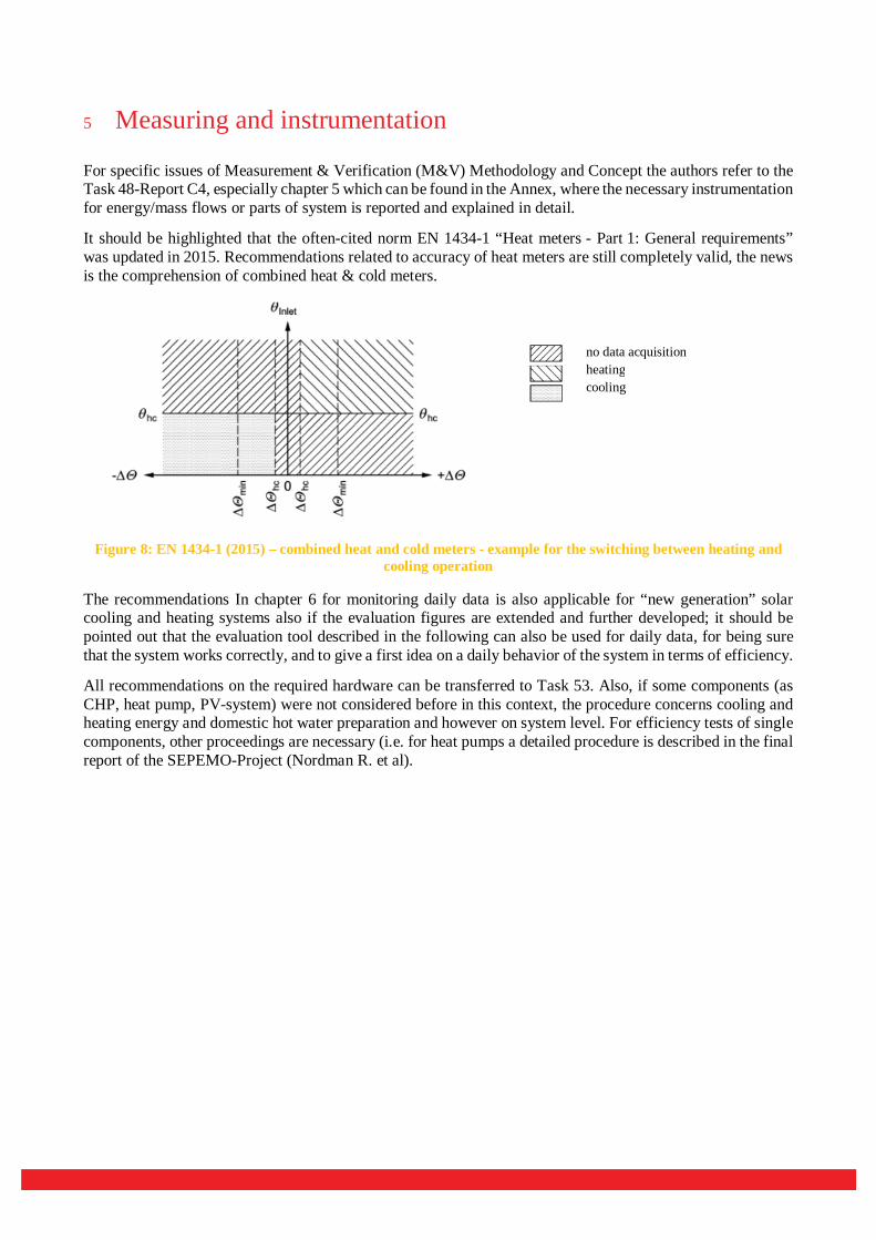
It should be highlighted that the often-cited norm EN 1434-1 “Heat meters - Part 1: General requirements” was updated in 2015. Recommendations related to accuracy of heat meters are still completely valid, the news is the comprehension of combined heat & cold meters.
Figure 8: EN 1434-1 (2015) – combined heat and cold meters - example for the switching between heating and cooling operation
The recommendations In chapter 6 for monitoring daily data is also applicable for “new generation” solar cooling and heating systems also if the evaluation figures are extended and further developed; it should be pointed out that the evaluation tool described in the following can also be used for daily data, for being sure that the system works correctly, and to give a first idea on a daily behavior of the system in terms of efficiency.
All recommendations on the required hardware can be transferred to Task 53. Also, if some components (as CHP, heat pump, PV-system) were not considered before in this context, the procedure concerns cooling and heating energy and domestic hot water preparation and however on system level. For efficiency tests of single components, other proceedings are necessary (i.e. for heat pumps a detailed procedure is described in the final report of the SEPEMO-Project (Nordman R. et al).
no data acquisition heating cooling

6 Bibliography [1] Boudéhenn F., Hands S., White S., Zahler C., Gammoh F.: “Deliverable M-C4.3 – Final report Measurement and Verification Procedures”, May 2013, IEA SHC Task 48
[2] Neyer, D., Thür, A., Fedrizzi, R., Vittoriosi, A., White, S., Focke: “Deliverable M-B7.2 - Collection of criteria to quantify the quality and cost competitiveness for solar cooling systems” , April 2015, IEA SHC Task 48
[3] Malenkovic, I., Eicher, S., Bony, J.: “Definition of Main System Boundaries and Performance Figures for Reporting on SHP Systems, A technical report of Subtask B, Deliverable B1.1, Final Document” Dec. 2012, IEA SHC Task 44, HPP Annex 38
[4] Napolitano, A., Sparber, W., Thür, A., Finocchiaro, P., Nocke, B.: “Monitoring Procedure for Solar Cooling Systems, A joint technical report of subtask A and B”, Sept. 2010, IEA SHC Task 38
[5] Nordman, R. et al: “SEasonal PErformance factor and Monitoring for heat pump systems in the building sector – Final Report 2012
[6] Norm EN 14825:2016-10 - Air conditioners, liquid chilling packages and heat pumps, with electrically driven compressors, for space heating and cooling - Testing and rating at part load conditions and calculation of seasonal performance
[7] Norm EN 1434-1:2015 - Heat meters - Part 1: General requirements
[8] Quiles P.V., Valero F.A.: “Deliverable D–C1.1 Monitoring Procedure for Field Test & Demo Systems with Compression Heat Pumps Driven by Photovoltaic Solar Energy, May 2013, IEA SHC Task 48
[9] Neyer D., Neyer J., Stadler K., Thür A. “TASK 53 Tool description”
Note : the IEA SHC Technology Collaboration Programme (IEA SHC TCP) functions within a framework created by the International Energy Agency (IEA). Views, findings and publications of the IEA SHC TCP do not necessarily represent the views or policies of the IEA Secretariat or of its individual member countries. The IEA SHC TCP and the IEA make no representation or warranty, express or implied, in respect of this paper’s content (including its completeness or accuracy) and shall not be responsible for any use of, or reliance on, the paper.


![THERMAL PRINTER TSP600 Series - Rice Lake Weighing …THERMAL PRINTER TSP600 Series TECHNICAL MANUAL [ FIRST EDITION ] NOTICE ... •Case unit according to the procedure described](https://img.dokumen.tips/doc/110x75/5e7c1b063376c00aed44b577/thermal-printer-tsp600-series-rice-lake-weighing-thermal-printer-tsp600-series.jpg)


