Embed Size (px)
Citation preview

978-1-5090-0128-6/16/$31.00 ©2016 IEEE
ADALINE Based LMS Algorithm in a Three Phase
Four Wire Distribution System for Power Quality
Enhancement
Trilochan Penthia Anup Kumar Panda,
Senior Member, IEEE Sunil Kumar Sarangi Mrutyunjaya Mangaraj
Department of Electrical Engineering, National Institute of Technology, Rourkela-769008, India
Abstarct—This paper describes a new control approach called
Adaptive linear neuron (ADALINE) based Least mean square
(LMS) algorithm used in a three phase four wire (3P4W)
distribution system under single phase fault condition. Three
phase reference supply currents are generated by using the
proposed control technique thereafter they compared with the
corresponding sensed supply currents to produce switching
pulses for the IGBTs of a four leg voltage source converter (4-
leg VSC) based distribution static compensator (DSTATCOM).
In this paper, the DSTATCOM is used for voltage regulation,
power factor correction and elimination of
distorted/unbalanced source current & excessive neutral
current in the system. MATLAB/SimPowerSystem environment
is used to simulate the distribution system under both fault and
without fault conditions.
Keywords— ADALINE; Power Quality Improvement; Custom
power device; THD; LMS algorithm; 3P4W distribution system
1. INTRODUCTION
Various types of outages and service interruptions in a
distribution system can cause serious damages in sensitive
industrial as well as domestic loads and computer based
controllers etc.. Generally, those outages and interruptions in
a three phase distribution system are caused due to faults,
device failure or unbalanced loading and they are termed as
power quality (PQ) problems [1-2]. PQ problems in a system
can be related to the supply current or voltage. Different
topologies and controllers are choosen as per the quality
problems related to either current or voltage in a power
system. Presence of harmonics in a power system can cause
serious problems like produce unwanted disturbances,
increasing losses in rotating machines and inaccurate
operation of control systems, protective devices, measuring
& communication equipment etc. [2-4].
To handle such type of PQ problems, many custom power
devices with different control techniques have been
introduced to improve the PQ in a distribution systems.
Custom power devices such as active power filters (APFs),
distribution static compensator (DSTATCOM), dynamic
voltage restorer etc. and control algorithms such as artificial
neural network (ANN), synchronous reference frame (SRF)
theory, power balanced theory (PBT) etc. [1-10].
Alleviation of harmonics, excessive neutral current due to
unbalanced load and reactive power in a distribution system
has been a great challenge for power engineers. These
problems create low power factor, system instability,
overheating and increase losses in the system.
This paper describes advantages of ADALINE based
LMS algorithm for control of DSTATCOM device.
DSTATCOM is a FACTS device used in a distribution
system for mitigation of power quality issues. Mainly,
DSTATCOM is a shunt type compensator, thereby it is used
for compensation of current quality related problems. The
ADALINE is a simple structured and high speed of data
processing type adaptive controller that offers excellent
performance in estimation of the variations in amplitude and
phase angle of the harmonic components. It has highly
convergence speed in tracking the harmonic components in
the system. Furthermore, this technique can also be
utilized in several disciplines of electrical engineering
including recognition of transient and steady-state
disturbances in high voltage transmission lines, frequency
tracking, detection & determination of current and voltage
signals in a three-phase unbalanced system [5-7]. The
proposed algorithm is used to extract the refernce source
current to generate switching signals for VSC of the
DSTATCOM by receiving different signals from several
parts of the system [8-10].
2. SYSTEM TOPOLOGY
A distribution system consist of a four wire nonlinear load
supplied by a three phase four wire ac supply. A VSC based
DSTATCOM is connected at the point of common coupling
(PCC) through an interfacing impedance (𝑍𝑐), as shown in
Fig.1. Generally, series connected impedance (𝑍𝑐) is
inductive in nature with an optimum resistance to eliminate
ripple in the supply current. The four-leg VSC of the
DSTATCOM consists of eight IGBTs and a DC-link
capacitor (𝐶𝑑𝑐). As IGBT is an ideal choice for a small to
medium rating electrical networks. Switching pulses for the
IGBTs of VSC are generated by using ADALINE based
LMS control algorithm and the control algorithm is
explained in next section below.

a- ph
b-ph
c-ph
3-ph, 4-wire(3P4W)
Uncontrolled
Bridge rectifier
(Non-linear load)
ila
ilb
ilcisc
isb
isa
ica iccicb
Zs
Zc
Source
C
Vdc
i*
sci*sbi
*sa
vdc(ref)
vdc
Hysteresis current
controller
Eight Switching signals
isa
isb
isc
ila ilb ilc
N
VSC
S1S7 S5 S3
S8 S6 S4 S2
i*
n
in
iln
vs
Load
Compensator
va
vb
vc
PCC
in
Fault
Reference currents generation
by using Adaline based LMS
algorithm
Fig.1: Schematic diagram of the proposed system
3. CONTROL ALGORITHM
In this section, the proposed ADALINE based control
strategy for the DSTATCOM is discussed. ADALINE is a
version of ANN technique and it functions as an efficient
controller in the whole compensation process. ADALINE
based LMS algorithm needs sensed supply voltage, DC-link
voltage and load currents as input parameters for its
calculation, as shown in Fig.2. The control approach involves
two steps to produce switching pulses required for the IGBTs
of the VSC-DSTATCOM as follows [4-5]:
A. Estimation of weighting value using ADALINE
based LMS algorithm
Let us consider the supply voltage of the three phase
system is purely sinusoidal and it can be given as:
𝑣𝑠 = 𝑉𝑚𝑠𝑖𝑛𝑤𝑡 (1)
The non-linear load current is given as:
𝑖𝑙 = 𝐼1 sin(𝑤𝑡 + ∅1) + ∑ 𝐼𝑛sin (𝑛𝑤𝑡 + ∅𝑛)
∞
𝑛=2
(2)
It can also be represented as,
𝑖𝑙 = 𝑖𝑙𝑝+ + 𝑖𝑙𝑞
+ + 𝑖𝑙ℎ− (3)
Where, 𝑖𝑙𝑝+ , 𝑖𝑙𝑞
+ , and 𝑖𝑙ℎ− are positive sequence active load
current, positive sequence reactive load current and negative
sequence load current (harmonic components) respectively.
The active component of current for a single phase is
obtained as,
𝑖𝑝 = 𝑊𝑚𝑢𝑠 (4)
Where, 𝑢𝑠 is the unit current template, calculated by
phase lock loop (PLL) concept and 𝑊𝑚 is the calculated
weight from ADALINE based LMS control algorithm.
Normally, this iterated weight depends on the magnitude of
the phase voltage and the load current.
𝑊𝑚(𝑘+1) = 𝑊𝑚(𝑘) + 𝜇[𝑖𝑙𝑘 − 𝑊𝑚(𝑘)𝑢𝑠(𝑘)]𝑢𝑠(𝑘) (5)
𝜇, is the step size of the convergence or also called as
convergence coefficient (varies from 0.1 to 1.0).
The unbalanced current in the system can be removed by
averaging the weights as follows:
𝑊𝑚+ =
(𝑊𝑚𝑎+ + 𝑊𝑚𝑏
+ + 𝑊𝑚𝑐+ )
3 (6)

B. Generation of reference source currents
DC-link voltage error for nth sampling instant is given by,
𝑣𝑑𝑐(𝑛)∗ − 𝑣𝑑𝑐(𝑛) = ∆𝑣𝑑𝑐(𝑛) (7)
Then the voltage error is fed to a PI controller and output of
the PI controller at the nth sampling instant is given as:
𝐼𝑠𝑚(𝑛) = 𝐼𝑠𝑚(𝑛−1) + 𝐼𝑃𝐼 (8)
Where, 𝐼𝑃𝐼 = 𝑘𝑝𝑑𝑐[∆𝑣𝑑𝑐(𝑛) − ∆𝑣𝑑𝑐(𝑛−1)] + 𝑘𝑖𝑑𝑐∆𝑣𝑑𝑐(𝑛)
and 𝑘𝑝𝑑𝑐 & 𝑘𝑖𝑑𝑐 are the proportional gain & the integral
gain of the PI controller respectively.
Now, the three phase reference source currents can be
calculated as:
𝑖𝑠𝑎∗ = (𝑊𝑚
+ + 𝐼𝑠𝑚)𝑢𝑠𝑎 (9)
𝑖𝑠𝑏∗ = (𝑊𝑚
+ + 𝐼𝑠𝑚)𝑢𝑠𝑏 (10)
𝑖𝑠𝑐∗ = (𝑊𝑚
+ + 𝐼𝑠𝑚)𝑢𝑠𝑐 (11)
Where, (𝑊𝑚+ + 𝐼𝑠𝑚) is considered as the magnitude of the
reference source current and 𝑢𝑠𝑎, 𝑢𝑠𝑏 and 𝑢𝑠𝑐 are the three
phase unit current templates.
Similarly, reference neutral current can be calculated as
follows:
𝑖𝑛∗ = 𝑖𝑠𝑎
∗ + 𝑖𝑠𝑏∗ + 𝑖𝑠𝑐
∗ (12)
Finally, the sensed source currents (𝑖𝑠𝑎 , 𝑖𝑠𝑏 & 𝑖𝑠𝑐) are
subtracted from the reference source currents (𝑖𝑠𝑎∗ , 𝑖𝑠𝑎
∗ , & 𝑖𝑠𝑎∗ )
and then the individual source currents error (including
neutral current error) are fed to a hysteresis current controller
(HCC) each separately to generate the switching pulses
(𝑆1, 𝑆2, 𝑆3, 𝑆4, 𝑆5, 𝑆6, 𝑆7 & 𝑆8) for 4-leg VSC of the
compensator, as shown in Fig.2.
+ -i
*n= (i
*sa+ i
*sb+ i
*sc)
in
ADALINE
ila
usa
Wma+
PI Controller
vdc
vdc(ref)+
-
i*
sa+
-
+ -
+ -
i*
sb
i*
sc
isa
isb
isc
ila
usa
ila
usa
ADALINE
ADALINE
+ + +
Wmb+
Wmc+
1/3
+ + Wm
+
Ism
(Wm++ Ism)
S5
S6
S3
S4
HCC2
HCC3
S7
S8HCC4
S1
S2HCC1
Fig.2: ADALINE based LMS control technique
4. SIMULATION RESULTS AND DISCUSSION
Simulations of the distribution system are carried out
under both fault condition and without fault condition in
MATLAB/SimPowerSystem environment. A comparative
simulation results of different performance parameters of the
system under aforementioned conditions are shown in table-
I. The system parameters taken in the simulation are listed in
table-II (in appendix section) . A single phase type fault
condition is considered (occurred between 0.6 sec to 0.7 sec)
in the ditribution system to check the effectiveness of the
DSTATCOM. The details of the compensation process are
described as follows:
(i) Without fault condition
The simulation of the proposed distribution system has been
performed successfully without considering any fault
conditions. Waveform of the sensed source voltage (𝑣𝑠),
neutral current & source current (𝑖𝑠), load voltage (𝑣𝑙), load
current (𝑖𝑙), compensating voltage (𝑣𝑐), compensating current
(𝑖𝑐) and DC-link voltage (𝑣𝑑𝑐) during simulation are depicted
in Fig.3. A comparative waveform of a-phase source current,
load current and compensating current, from top to bottom,
are given in Fig.4. Total harmonic distortion (THD) of the
source current and load current are obtained 3.51% and
21.30% respectively, shown in Fig.5 and Fig.6.
Fig.3: Source voltage, source current, load voltage, load current,
compensating voltage, compemsating current and dc link voltage.
Fig.4: Source current, load current and compesating current
-5000
500
vs (
V)
-1000
100
i s (
A)
-5000
500
vl (V
)
-100
0
100
i l (A
)
-5000
500
vc (
V)
0.5 0.55 0.6 0.65 0.7 0.75 0.80
500
Time (Sec)
vdc (
V)
-50
0
50
i c (
A)
-50
0
50
i sa (
A)
-50
0
50
i la (
A)
0.5 0.55 0.6 0.65 0.7 0.75 0.8-20
0
20
Time (Sec)
i ca (
A)
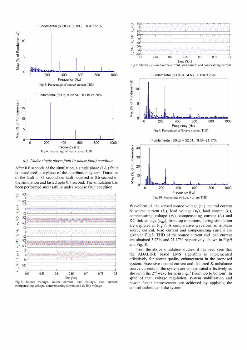
Fig.5: Percentage of source current THD
Fig.6: Percentage of load current THD
(ii) Under single phase fault (a-phase fault) condition
After 0.6 seconds of the simulation, a single phase (1-L) fault
is introduced at a-phase of the distribution system. Duration
of the fault is 0.1 second i.e. fault occurred at 0.6 second of
the simulation and lasted upto 0.7 second. The simulation has
been performed successfully under a-phase fault condition.
Fig.7: Source voltage, source current, load voltage, load current,
compensating voltage, compemsating current and dc link voltage.
Fig.8: Shows a-phase Source current, load current and compesating current
Fig.9: Percentage of Source current THD
Fig.10: Percentage of Load current THD.
Waveform of the sensed source voltage (𝑣𝑠), neutral current
& source current (𝑖𝑠), load voltage (𝑣𝑙), load current (𝑖𝑙),
compensating voltage (𝑣𝑐), compensating current (𝑖𝑐) and
DC-link voltage (𝑣𝑑𝑐), from top to bottom, during simulation
are depicted in Fig.7. A comparative waveform of a-phase
source current, load current and compensating current are
given in Fig.8. THD of the source current and load current
are obtained 3.75% and 21.17% respectively, shown in Fig.9
and Fig.10.
From the above simulation studies, it has been seen that
the ADALINE based LMS algorithm is implemented
effectively for power quality enhancement in the proposed
system. Excessive neutral current and distorted & unbalance
source currents in the system are compensated effectively as
shown in the 2nd wave form, in Fig.7 (from top to bottom). In
spite of that, voltage regulation, system stabilization and
power factor improvement are achieved by applying the
control technique in the system.
0 200 400 600 800 10000
5
10
Frequency (Hz)
Fundamental (50Hz) = 53.89 , THD= 3.51%
Mag (
% o
f F
undam
enta
l)
0 200 400 600 800 10000
5
10
15
Frequency (Hz)
Fundamental (50Hz) = 52.54 , THD= 21.30%
Mag (
% o
f F
undam
enta
l)
-5000
500
vs (
V)
-100
0
100
i s (
A)
-100
0
100
i l (A
)
-5000
500
vc (
V)
-50
0
50
i c (
A)
0.5 0.55 0.6 0.65 0.7 0.75 0.80
500
Time (Sec)
vdc (
V)
-5000
500
vl (V
)
-50
0
50
i sa (
A)
-50
0
50
i la (
A)
0.5 0.55 0.6 0.65 0.7 0.75 0.8-50
0
50
Time (Sec)
i ca (
A)
0 200 400 600 800 10000
5
10
Frequency (Hz)
Fundamental (50Hz) = 54.63 , THD= 3.75%
Mag (
% o
f F
undam
enta
l)
0 200 400 600 800 10000
10
20
30
40
Frequency (Hz)
Fundamental (50Hz) = 52.01 , THD= 21.17%
Mag (
% o
f F
undam
enta
l)

Table-I: Comparison of different performance parameters
Performance parameter Without fault
condition Under single phase
(a-ph) fault condition
Source current (A) 53.89 54.63
THD of source current 3.51 % 3.75 %
Load current (A) 52.54 52.01
THD of load current 21.30 % 21.17 %
5. CONCLUSION
In this paper, the distorted supply current, excessive neutral
current and low input power factor due to presence of single
phase fault and nonlinear load in the system are compensated
successfully by using the DSTATCOM with a novel control
approach called ADALINE based LMS algorithm. The three
phase source current found from the simulation results are
balanced and its THD is below 5%, thereby satisfying the
IEEE-519 standard on harmonic limits. Also, voltage
regulation and reactive power compensation are achieved by
using the proposed control technique effectively.
Appendix
Table-II: System parameters for simulation studies
Source side
Source voltage, (𝑣𝑠)= 230V,50Hz
Source resistance, (𝑅𝑠)= 0.01 Ω
Source inductance, (𝐿𝑠)= 2 mH
Load side
3-phase diode rectifier with RL load
Resistance = 20 Ω
Inductance = 10mH
Compensator (DSTATCOM)
DC-link voltage, 𝑉𝑑𝑐(𝑟𝑒𝑓)= 700V
DC-link capacitor, 𝐶𝑑𝑐= 2050 μF
Compensating resistance, 𝑅𝑐= 0.10 Ω
Compensating inductor, 𝐿𝑐= 25 mH
PI gain: KP,= 10.45 , KI = 0.15
6. REFERENCES
[1] Hirve S., Chatterjee, K., Fernandes B.G., Imayavaramban M., Dwari
S. "PLL-Less Active Power Filter Based on One-Cycle Control for
Compensating Unbalanced Loads in Three-Phase Four-Wire System," IEEE Transactions on Power Delivery, vol.22, no.4, pp.2457-2465,
Oct. 2007.
[2] Lee J., Lee K. "Open-Circuit Fault Tolerant Control for Outer Switches of Three-Level Rectifiers in Wind Turbine Systems," IEEE
Transactions on Power Electronics, Issue.99, pp.1-1. 2015.
[3] Singh B., Jayaprakash P., Somayajulu T.R., Kothari D.P. "Reduced Rating VSC With a Zig-Zag Transformer for Current Compensation
in a Three-Phase Four-Wire Distribution System," IEEE Transactions
on Power Delivery, vol.24, no.1, pp.249-259, Jan. 2009.
[4] Bhattacharya A., Chakraborty C. "ANN (Adaline) Based Harmonic
Compensation for Shunt Active Power Filter with Capacitor Voltage Based Predictive Technique," in Proc. Industrial and Information
Systems, 2008 (ICIIS 2008.), IEEE Region 10, pp.1-6, 8-10 Dec.
2008. [5] Dash P.K., Panda S.K., Mishra B., Swain D.P. "Fast estimation of
voltage and current phasors in power networks using an adaptive
neural network," IEEE Transactions on Power Systems, vol.12, no.4, pp.1494-1499, Nov 1997.
[6] Fahmy A., Hamad M.S., Abdelsalam A.K., Lotfy A. "Power quality
improvement in three-phase four-wire system using a shunt APF with predictive current control," in Proc. 38th Annual Conference on IEEE
Industrial Electronics Society (IECON 2012), pp.668-673, 25-28 Oct.
2012. [7] Vodyakho O., Mi C.C. "Three-Level Inverter-Based Shunt Active
Power Filter in Three-Phase Three-Wire and Four-Wire Systems,"
IEEE Transactions on Power Electronics, vol.24, no.5, pp.1350-1363, May 2009.
[8] Geddada N., Karanki S.B., Mishra M.K., Kumar B.K. "Modified four
leg DSTATCOM topology for compensation of unbalanced and nonlinear loads in three phase four wire system," in Proc. Power
Electronics and Applications (EPE 2011), pp.1-10, Aug. 30 2011-
Sept. 1 2011. [9] Nava-Segura A., Mino-Aguilar G. "A novel four-branches-inverter-
based-active-filter for harmonic suppression and reactive
compensation of an unbalanced three-phase four-wires electrical distribution systems, feeding AC/DC loads," in Proc. IEEE 31st
Annual Power Electronics Specialists Conference, 2000 (PESC-2000), pp.1155-1160 vol.3, 2000.
[10] Singh Bhim, Kasal G.K., Chandra A., Kamal-Al-Haddad "Improved
Power Quality Based Controller for a 3-Phase 4-Wire Isolated Wind Energy System," in Proc. Electrical Power Conference, 2007 (EPC
2007), IEEE Canada , pp.531-536, 25-26 Oct. 2007.


![Introdução e Principais Conceitos - feis.unesp.br · A rede neural MADALINE (Multi-ADALINE) ([9]) é constituída por vários elementos ADALINE. Contudo, o processo de treinamento](https://img.dokumen.tips/doc/110x75/5b5051d47f8b9a206e8e4bdf/introducao-e-principais-conceitos-feisunespbr-a-rede-neural-madaline-multi-adaline.jpg)