Embed Size (px)
Citation preview

r ADA 09635-1 ILEVEEt
AVRADCOMReport No. TR 81-F-3 _AD__
MANUFACTURING METHODS AND TECHNOLOGY(MANTECH) PROGRAM
ULTRASONIC COLD FORMING OFAIRCRAFT SHEET MATERIALS
JANET DEVINE and PHILIP C. KRAUSE MAP"1Sonobond Corporation200 East Rosedale AvenueWest Chester, Pennsylvania 19380 E
January 1081 FINAL REPORT
Contract No. DAAG-79-C-0001
Approved for public release;distribution unlimited
LU... U.S. ARMY AVIATION RESEARCH AND DEVELOPMENT COMMAf1D
S8•3 i 3 018

The findings in this report are not to be construed as an officialDepartment of the Army position, unle-s so designated by otherauthorized documents.
Mention of any trade names or manufacturers in this reportshall not be constlued as advertising nor as an officialindorsement or approval of such products or companies bythe United States Government.
DISPOSITION INSTRUCTIONS
Destroy thistet when it Is no km nleded.Do not return It to the originator.
- -----

UNCLASSIFIEDSECURITY yCLASSI•ICATION OF THIS PAGE Monia, D00. lIa.go
REPORT G READ INSTRUCTIONS_____________________________f D EFORECOMPLErTINGFORM
1. AIEPOAT NUIF A - G.OVT ACCESSION NO. 1. RIMc I NT' *et- LOt 1vtvIerl
AVRADCOMTR81i- r-3- C.7 41 4 --1I.. T~A~M% iP 44A...
iULTRASONIC COLD.FORMING OF tIRCRAFT Y-hAWFinal -e6. orSHEET MATERIALS -J7 Nov 8 L ?-• Oms•-W5~tORw- uwgffr--... . -4
SResearch Report 80-8 •7. #THO.R~o•.. :-- O CONTRACT OR GRANT NUMBE[R(&)
"Janet DevineSPhilip C../Krause DAAG46-79-C- oo'Z f r,
9. PERFOIRMING ORGANIZATION NAME AN1 ADDRESS 10, PROGRAM ELEMENT. PROJECT. TASKAREA & WORK UNIT NUMBERSSonobond Corporation D/A Project: 1777052
200 East Rosedale Avenue AMCMS Code: 1497--90-7-West Chester, PA 19380 57052
II. CONTROLLING OFFICE NAME AND AODRESS V-"
US Army Aviation Research & Development ___/Jar_____ ____SI_
Command, ATTN: DRDAV-EGX -714300 Goodfellow Blvd.. St. Louis. MO 6117n
14. MONITORING AGENCY NAME & AOORESS(II dilferemn Itra Controlling Office) IS. SECURITY CLASS. (calehl ropt)
Army Materials & Mechanics Research CenteATTN: DRXMR-AP UNCLASSIFIEDWatertown, MA 02172 'So. DlCLASSIFICATION/DOWNGRAOINGWaerow, JfLI.SCN4EOUtE
16. DISTRIBUTION STATEMENT (of this Report)
Approved for public release.;-distribution unlimited.
17. DISTRIBUTION STATEMENT (of the absract oiered In Block 20. il ddllormit from Report)
IS. SUPPLEMENTARY NOTES
Prepared in cooperation with Hughes Helicopters, Culver City,CA 90230AMMRCTR81-1
I9. KEY WORDS (Contlnue on reverse side II necessary and Identify by block number)
UltrasonicsMetal WorkingTitaniumSteelNickel
!0. ABSTRACT (C3i*itue an rote a.• tide If necessary and ldenfl(y by block number)
-',Ultrasonic forming war investigated as a means for shaping air-craft sheet materials, including titanium 6A1-4V alloy, nickel,and stainless steel AM355-CRT, into a helicopter rotor blade nosecap contour. Equipment for static forming of small coupons con-sisted of a modified 4000-watt ultrasonic spot welder providcedwith specially designed punch and die sets. The titanium alloywas successfully formed to a 60-degree angle in one step with.l
DD I FAw" 1473 EDITION o, 1 NOV15 IS OBSOLETE UNC-ASSIFIEDSECURITY CLASSUIICATION OF THIS PAGE (when Dots Enteed)7( 44 __

77
SUTCLASSI ED "A
Block No. 20
ultrasonics, but invariably cracked under static force alone.Nickel had a low enough yield strength that it could be suc-cessfully formed either with or without ultrasonics. Insuf-ficient ultrasonic power was available to produce beneficialeffect with the high-strength steel. From analogy with commer-cially used ultrasonic tube drawing, it was postulated that dy-namic forming of long lengths of the nosecap geometry could beachieved with an ultrasonic system mounted on a drawbench. It"was recommended that the ultrasonic technique be considered forforming other aircraft sheet geometries, particularly involvingt•itanium alloy.
,t
iF
UNCLASSIFTEDSCCUMITT CLASSFICATION OF THIS PAGE(19ih. 0•.. C.1.'ld)
_77TM-C77 7
PREFACE
This report on ultrasonically assisted forming of air-craft parts was prepared by Sonobond Corporation, West Chester,PA, under Army Contract DAAG46-79-C-0001. This project wasaccomplished as part of the US Army Aviation Research andDevelopment Command Manufacturing Technology program. Theprimary objective of this program is to develop, on a timelybasis, manufacturing processes, techniques, and equipmentfor use in production of Army materiel. Comments are solic-ited on the potential utilization of the information containedherein as applied to present and/or future production pro-grams. Such comments should be sent to: US Army AviationResearch and Development Command, ATTN: DRDAV-EGX, 4300Goodfellow Boulevard, St. Louis, MO 63120.
Mr. Arthur M. Ayvazian of the Army Materiels and Mech-anics Research Center, ATTN: DRXMR-AP, Watertown, MA, servedas Contracting Officer's Representative on this project.The work at Sonobond was under the technical supervision ofMrs. Janet Devine, and Philip C. Krause served as administra-tive supervisor.
Assistance in the program was provided by Hughes Heli-copters, Division ot Summa Corporation, Culver City, CA, withKenneth Niji providing technical liaison.
The findings of this report are not to be construed asan official Department of the Army position.
Accession For
NTIS G"',&liDTIC V?
* L
•Iist __ _I

TABLE OF CONTENTS
INTRODUCTION .......... ..................... 1
Conventional Nosecap Forming Processes ... ..... 1
Background of Ultrasonic Metal Forming 2..... 2
Approach . . . . . . . . . . . . . . . . . . . . 9
MATERIALS ........... ...................... ... 13
ULTRASONIC STATIC FORMING EQUIPMENT ........... ... 15
Ultrasonic System ...... ............... .. 15
Tooling .......... .................... .. 18
EXPERIMENTAL INVESTIGATIONS ......... ............. 28
Preliminary ExDeriments .......... ............ 28
Preparation of Evaluation Samples .. ....... .. 30
Hughes Evaluation of Samples ... .......... .. 32
Preparation and Evaluation of Additional TitaniumSamples .......... .................... .. 36
ULTRASONIC DYNAMIC FORMING EQUIPMENT ........ 42
CONCLUSIONS AND RECOMMENDATIONS ... ........... .. 47
vU

LIST CF ILLUSTRATIONS
1 Ultrasonic effect on rolling of 1/8-inch
diameter zinc wire ........ ............ 4
2 Aluminum sheet drawn with and withoutultrasonic activation ....... .......... 5
3 Titanium rods cold-drawn with and
without ultrasonics ....... ........... 6
4 Cold bending of 6A1-4V titanium alloy
both statically and with ultrasonics . . . 8
5 Cross section of helicopter rotor blade 10
6 Main rotor blade leading edge contour 11
7 Standard 4000-watt ultrasonic spotwelder ...... .................. ... 16
8 Piezoelectric tension-shell transducerwith 4000 watts power rating ....... ... 17
9 Side view of single ultrasonic subsystem 19
10 Anvil modified for ultrasonic formingsystem ...... .................. ... 20
11 Ultrasonic machine modified for formingoperations ..... ................ ... 21
12 4000-Watt ultrasonic frequency converter . 22
13 Punch and die set for bending to 60-degreeangle and 0.168-inch radius ....... .. 24
14 Punch and die set for 45-degree anglebend ........ ................... ... 25
15 Intermediate tooling for 90-degree anglebend with 0.375-inch radius ....... .. 27
vi

LIST OF TABLES
Table Page
1 Material properties ...................... 14
2 Ultrasonic equipment specifications ... ..... 23
3 Preliminary bending of titanium specimens . 29
"4 Included angles of evaluation samples .... 31
5 Included angles between logs .. ........ .. 33
6 Hughes measurements of nose radii ...... ... 34
7 Burnt pit distribution of stainless steel . 35
8 Hardness near pit area, ultrasonicallyformed steel ..... ................ .. 37
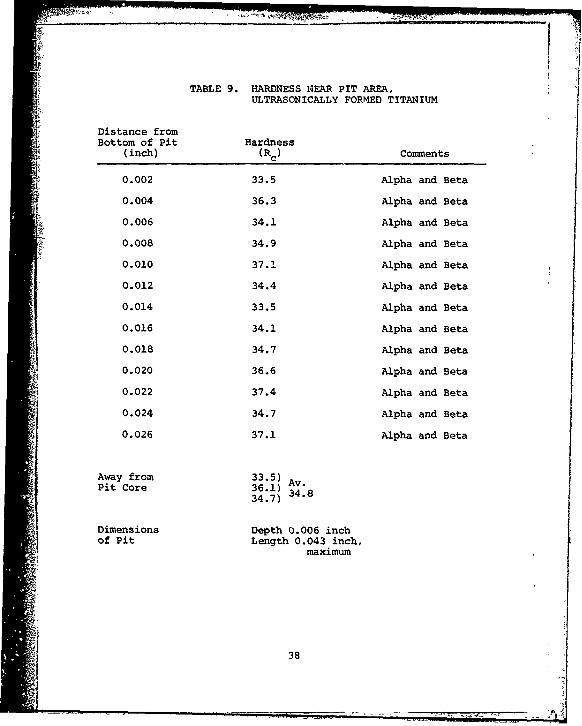
9 Hardness near pit area. ultrasonicallyformed titanium .......... ............... 38
10 Hardness near pit area, ultrascnicallyformed nickel ..... ................ ... 39
11 Additional samples of titanium 6A1-4VPalloy examined ..... .............. ... 41
12 Specification for an ultrasonic drawbench . 43
13 Specifications for 20,000-pound ball screw tdrawbench complete with accessories ... ..... 45 1
viii
vail

INTRODUCTION
The objective of this program was to apply ultrasonicenergy to the processing of aircraft sheet materials as ameans of improving the forming and processing of helicopterrotor blade nosecaps. The metals of particular interest werenickel 200, 6A1-4V titanium alloy, and AM355-CRT stainlesbsteel.
Ultrasonic activation has been demonstrated to producesignificant benefits In the cold forn.ing of metals, such asdecrease in static force requirement, increasing in processingrates, reduction in the number of processing steps, and im-provement in product quality, particularly in surface finishand dimensional tolerances. Such effects have been unmistak-ably demonstrated in such ultrasonic deformation processesas forging, extrusion, tube, rod, and wire drawing.
This type of cold forminy could have a decided impacton the fabrication of helicopters. The cost effectivenessof the process would be reflected almost immediately in theproduction of various sheet metal shapes, and in particularthe nosecap of the helicopter rotor blade. In this program,ultrasonic activation was examined as a technique to mini-mize incipient cracks, reduce springbacK, improve repeatabil-ity of the blade geometry, and maintain high fatigue strengths.
The contract initially called for a three-phase program.Phase I involved the development of a static ultrasonic form-ing system and its evaluation in forming of an AAH helicopterblade contour, with optimization of the independent parametersand evaluation of thr quality of the ultrasonically formedmaterials. Phase II was oriented to extending the processto ultrasonic dynamic forming of nosecap specimens on a draw-bench using a single module ultrasonic system, and Phase IIIinvolved further evaluation of the dynamic process with atriad ultrasonic system.
During the conduct of Phase I, rapid development wasmade in composite blade materials as a replacement for metalin the fabrication of helicopter rotor blades. For this reason,and due to cost escalation for Phases II and III, the Govern-ment elected to consider the work complete at the conclusionof the first phase.
CONVENTIONAL NOSECAP FORMING PROCESSES
Most rotor blades presently in service throughout theworld use metallic sheet that has been hot formed for the
1!

leadlng edge erosion-resistant nosecap. Ordinarily the nosecapis stainless steel, titanium alloy, or nickel. These materialsare expensive, and the forming is usually a slow, costly pro-cess, sometimes involving high temperatures which degradethe surfaceg. For example, the forming of titanium alloysheet mSterial i~to aeronautical surfaces is usually accomplishedat 1400 to 1600 F. Expensive chemical agent and cleaningprocedures are required to restore the titanium surfaces aftersuch heating.
Titanium also exhibits springback during the sheet formingprocess. This springback involves elastic recovery of themetal, which is usually a function of the elastic strain presentin the total deformation. Many attempts have been made todescribe the forming process theoretically and to accuratelyI predict springback for a variety of materials under formingconditions. If sufficient stress is applied to exceed theelastic limit and eliminate springback, the metal has a ten-dency to crack.
Ultrasonic cold forming would minimize the required cleaningprocedures, and would be expected to reduce springback, reduceincipient cracking, improve the repeatability of blade geometry,and maintain high fatigue strengths.
BACKGROUND OF ULTRASONIC METAL FORMING
The potential payoff for ultrasonic cold forming of metalshas a solid basis in past experimental and production activities.The beneficial effects have been unmistakably demonstratedin both tension and compression forming processesz tube, wire,and rod drawing; stretch forming, as in deep drawing, drawironing, tube flaring, and dimpling; primary metal workingby rolling and extrusion; and bending and straightening.
The discovery that metals deform more readily under ultra-sonic influence dates back to the mid-1950's,* when fine metalwires stressed in tension with ultrasonic activation showedsubstantial reduction in yield strength and increase in elon-gation. The magnitude of the effect was independent of fre-quency but increased linearly with increase in vibratory power.This phenomenon was attributed to ultrasonically facilitatedformation and movement of dislocations within the crystallattice structure, so that intercrystalline slip could takeplace more readily. Thus ultrasonically activated metals
*F. Blaha and B. Langenecker, "Dehnung von Zink-Kristallenunter Ultraschalleinwirkung," Die Naturwissenschaften, Vol.42, 1955, p. 556; ibid., "Untersuchungen zur Bearbeitung-serholung (Verformungsentfestigung) von Metallkristallen,"Zeitschrift fur Metallkunde, Vol. 49, 1958, p. 357-360.
2

exhibit a type of superplasticity which is not evident inordinary static stressing.
In addition, and particularly in dynamic metal formingprocesses, there is significantly reduced friction betweenthe workpiece and the forming die, which adds an additional
dimension to the ultrasonic effect. This friction-reducingeffect has been demonstrated independent of the plasticityeffect, as for example in the assembly of close toleranceparts or the torgue tightening of threaded fasteners. Thisphenomenon is particularly important in dynamic forming pro-cesses such as tube and wire drawing, extrusion, and rolling,in which the workpiece makes moving contact with the formingtool.
Typical effects of ultrasonically activated forming areillustrated in Figures l and 2. Figure 1 shows the increaseddeformation obtained in the flattening of zinc wire with aroller device maintained under constant static force. Theultrasonically induced deformation was approximately twicethat obtained with static force alone. In draw forming alum-inum to the configuration shown in Figure 2, the use of onlystatic force induced cracking of the metal in the area ofgreatest deformation. No such cracking was obtained withthe superimposition of ultrasonic energy. Similar resultshave been obtained in the draw ironing of aluminum and brasscartridge cases, in the flange flaring of metal tubing, andin the dimpling of aircraft materials.*
Production problems in ultrasonic forming have been suc-cessfully solved with the evolution of tube drawing insatlla-tions involving ultrasonic activation of either the draw dieor the internal mandrel or both. Several such installationsare routinely used in metal tubing production both in theUnited States and abroad. This experience is particularlysignigicant since a drawbench operation was projected forthe dynamic forming aspect of this program. The materialsdrawn span the spectrum from soft aluminum and copper to hardtitanium and steel. The benefits are reflected in both re-duced costs and higher quality tubing: reduced draw forces,increased area reduction per pass, increased drawing rates,elimination of stick-slip and chatter, smoother surface finish,improved dimensional control over long lengths, and increaseddiameter-to-wall-thickness ratios. The improved surface fin-ish with the elimination of the stick-slip phenomenon is illus-trated in the ultrasonically drawn titanium rods of Figure 3.
* F. R. Meyer, "Engineering Feasibility Study of UltrasonicApplications for Aircraft Manufacture," Research Report73-15, Army Contract DAAJ01-72-C-0737(PlG), AeroprojectsIncorporated, West Chester, PA, September 1973.
3

Crcss section of wirebefore rolling
Vt
Rolled with 1000 poundsnormal force(Thickness reduced to0.098 inch)
Rolled with 1000 poundsnormal force and ultra-sonic application at3000 watts poweri (Thickness reduced to-0.0625 inch)
Figure 1. Ultrasonic effect on rolling of 1/8-inch-diameterzinc wire (30X magnification).
4
- -- I-

!to
Figure 2. Aluminum sheet, 0.020 inch thick, drawn withand without ultrasonic activation.
A. Non-vibrated specimen.
B. Vibrated specimen produced withsame static load as A.
C. Non-vibrated specimen drawn withsufficient static load to achievesame depth as B. (Note tear atarrow.)
5

Group drawn with and without ultrasonics
4 5 8 7
Drawn without ultrasonics
Drawn with ultrasonics
Figure 3. Titanium rods cold-drawn with andwithout ultrasonics.
;6

The ultrasonic effect on bending of hard metal strips
and panels has likewise been addressed. Several years ago,*work was done in the bending and twisting of 1-inch-wide rib-bons of 304 and 17-4 PH stainless steel 0.100 inch and 0.125inch thick. Reduction in springback of the metal was of pri-mary interest. When the strips were bent to angles rangingfrom 10 to 60 degrees, ultrasonic activation increased theresidual angle by 290 percent at the smallest angle to 13percent at the largest angle. With twist angles in the rangefrom 10 to 25 degrees, the residual twist angle increasedby 10 to 100 percent with ultrasonic activation. The decreasedeffect at the larger angles was related to the constant ultra-sonic power level used throughout the tests. No microstruc-tural differences were found between the ultrasonically andnon-ultrasonically bent samples.
Moce recent work** involved the drape forming of 6A1-4Vtitanium alloy panels 0.040 inch thick by 4 inches wide by16 inches long. Preliminary studies with tensile stressingof metal strips and dumbbell specimens established a reduc-tion of about 15 percent in the yield and ultimate strengthsof the material with ultrasonic activation. For the panelspecimens, ultrasonic energy was transmitted directly intothe titanium sheet via several transducer-coupling systemsbraze-attached to the sheets. This arrangement was used totypify the non ultrasonic drape forming process then underconsideration for this forming process. The configurationsimulated the leading edge of a helicopter rotor blade. When
bent with static force alone, the residual included anglewas 108 degrees; with superimposed ultrasonics, the includedangle was 97 degrees, approximately 10 percent improvement.With this arrangement, it was concluded that transmission ofthe energy into the titanium was not the most efficient ap-proach because of the intrinsically low acoustic impedanceof the sheet geometry.
Additional experiments were carried out with an ultra-sonically activated punch mounted on a standard ultrasonicspot welder, using the arrangement shown at the top in Fig-ure 4. When titanium alloy sheet 0.050 inch thick was de-formed under a static force of 700 pounds, little indentationwas obtained. With the same force and 2000 watts ultrasonicactivation, a full 90-degree bend was obtained, and the resid-
* N. Marpois, W. H. Bayles, J. Devine, and F. R. Meyer, "Ultra-sonic Application to Facilitate Straightening of Steam Tur-bine Blades," Research Reort 70-31, Aeroprofects Incorpor-ated, West Chester, PA, November i970.
** H. A. Scheetz, "Ultrasonic Cold Forming of Titanium,' ResearcbReport 77-8, Sonobond Corpotation, West Chester, PA. May J9777
*1 7

S90-90
Ultrasonic Spot3 Welder Tip-.R
8S- Ultrasonic Displacement
'--0.050-inch 6A1-4V Titanium\ Alloy, 7/8" wide x 3-1/4"1
Anvil long
••;L ; = 700 poundsNo ultrasonics
SO700 pounds + 2000watts ultrasonicsfor 3 seconds
o 700 pounds + 2000106 watts ultrascnicsfor 5 seconds
0 1000 poundsNo ultrasonics
Figure 4. Cold bending of 6A1-4V titanium alloy,both statically and with ultrasonics.
8

ual included angle was 106 degrees. With 1000 pounds static i
force alone, the residual angle was 111 degrees.
Since the efforts described above, further advances havebeen made in the ultrasonic equipment adaptable to such formingprocesses and particularly in the power capabilities of suchequipment. Whereas the maximum power used in the earlierwork was 2000 electrical watts input to the transducer, equip-ment of 4000 watts capacity is now routinely used for a varietyof applications, including ultrasonic spot welding. In addition,both transducers and coupling systems have been made moreefficient, and the principles of acoustic transmission intoforming tools have been more clearly defined.
APPROACHAs noted, the program objective was to develop and eval-
uate a system for utilizing ultrasonic energy to assist informing helicopter rotor blade nosecaps to final dimensions.The selected configuration was the H-64 helicopter rotor bladewhich had the cross-sectional configuration shown in Figure 5.
The most critical portion of this section was the 60-degree angle at the leading edge of the profile, shown inFigure 6. This area had an outside radius of 0.168 inch.The specifications called for a maximum allowable contour:deviation of + 0.008 inch and a thickness deviation not toexceed + 0.005 inch.
The first phase of the work involved static forming ofsmall coupons to the required contour. Phase II would involvedynamic forming of extended lengths to this contour, usinga drawbench to translate the workpiece through the formingtools. Under Phase III, a triad ultrasonic system would beused to activate a larger area of the leading edge profilein a dynamic arrangement. Such a system would cover a 4.5-inch section of the leading edge, which was the critical areafor forming. The areas toward the trailing edge of the rotorblade presented no critical forming problem.
The static forming activity of Phase I was carried outwith the support and cooperation of Hughes Helicopters, CulverCity, California, who supplied the materials for forming andconducted evaluations of the formed parts. V
The basic ultrasonic equipment was a standard 4000-wattultrasonic spot welder which had the capability of applyingstatic loads up to about 3000 pounds. This system was modi-fied to meet the requirements of the forming operation, andspecial punch and die sets to provide the required contourwere designed and fabricated.
9

.4
.4-.0G .&0O(Typ.)
501 (TYR)
IP-ONTUR--• --- CHORD LINE
Figure 5. Cr0ss section of helicopter rotor blade.
010
7.0 RE.IEAL

'524
21 .2o9
II
II
S~Figure 6. Main rotor blade leading edge contour.
=• (Scale - 5:1)
A 11 V

With this equipment, parameters of static force, ultra.-sonic power level, and dwell time were established for form-ing coupons of the requisite materials: rickel 200, 6A1-4Vtitanium alloy, and AM355-CRT stainless steel. Modificationsin the equipment and procedures were made as the work pro-gressed. Samples of the formed specimens were forwarded toHughes Helicopters for dimensional and hardness measurementsand metallographic examination.
Meanwhile consideration was given to the acquisitionof a dvnamic system that would be suitable for forming ex-tended lengths of the nose section in the single or triadmodule arrangement. Since it appeared that this could bemost effectively accomplished with a commercial type draw-bench, a survey was made of drawbench manufacturers, and aunit fulfilling the required specifications was selected.The equipment assembled for the static forming of Phase Iwas designed for mounting on such a drawbench.
The dynamic forming phase of the investigation was sus-pended as a result of funding limitations and the prospectof the composite rotor blade gaining acceptance in the industry.The cold forming of titanium which was accomplished withinthe scope of this program offers promise to the aerospace de-signer for use of a process whereby ultrasonic energy canassist the cold forming of selected aerospace materials.
12
- 71
MATERIALS
The workpiece materials provided by Hughes Helicopters
were:
1. Nickel, 6R200 Huntington Alloy
2. Titanium 6A1-4V alloy
3. Stainless steel AM355-CRT.
Basic pertinent properties of these materials in the longi-tudinal direction are given in Table 1.
It was originally intended that these materials beevaluated in a thickness of 0.040 inch. However, the titaniumalloy and nickel were not available in this thickness, and0.050-inch material was substituted in these materials.The steel was used in the 0.040-inch thickness. Couponsof each material were 1.5 inches wide by 2 inches long.The change in thickness after the work was initiated neces-sitated fabrication of additional tools, as described later.
Review of the property data in Table 1 indicates thatnickel is the most readily formed of these materials becauseof its low yield strength and high elongation. This wasverified in the experimentation. The nosecap geometry couldbe readily achieved even without the nse of ultrasonics.On the other hand, the steel has a very high yield strengthand low elongation. Early in the program it was determinedthat cold forming of this material in the thickness requiredfor efficient nosecaps was somewhat beyond the capabilitiesof the existing ultrasonic forming equipment. Accordingly,the principal effort was directed to examination of titaniumalloy 6A1-4V as the most likely candidate for the nosecaps.
if
13
I~IA

TABLE 1. MATERIAL PROPERTIES
Property Steel Titanium Nickel
Young's Modulus (psi)(a) 25.7 x 10⁶ 17.5 x 10⁶ 30.0 x 10⁶
" Yield Strength (psi) (b) 200,000 126,000 34,000
Tensile Strength (psi) (b) 220,000 140,000 61,000
Elongation (%b) 12 10 43
" Hardness (Rockwell) (c) 47 Rc 33 Rc 47 Rb
(a) From ASM Metals Handbook
(b) Data from Hughes Helicopters
(c) Measured values IStated properties are parallel to the rolling direction
- (longitudinal).
i! 1I L
14 I1!
I 1~ -

ULTRASONIC STATIC FORMING EQUIPMENT
ULTRASONIC SYSTEM
The ultrasonic equipment selected for the static formingoperation consisted of a standard 4000-watt ultrasonic spotwelder, which provides the basic required parameters: meansfor introducing ultrasonic energy through appropriatelydesigned tools into the workpiece, a hydraulic system forstatic force application, and a timer to provide finiteduration of the ultrasonic application. Figure 7 showsthe standard welder before modification.
This equipment incorporates a wedge-reed transducer-coupling system consisting of a resonant reed and a trans-ducer and wedge coupler perpendicular to the reed. Thetransducer-coupling system drives the reed in flexure, in-ducing lateral vibration of the forming tool located atthe terminus of the reed. Static force is applied frombelow through the anvil and is reacted by the mass supportingthe reed.
The standard transducer for this assembly (Figure 8)consisted of disks of lead zirconate titanate polarizedin the thickness mode, incorporated in a rugged assemblyof the tension-shell type with a bias compressive stresson the ceramic disks to preclude failure under dynamic stress.Cooling channels permitted cooling air flow through theassembly to prevent overheating and depolarization of thetransducing elements. The transducer operated at a nominalfrequency of 15 kilohertz and had a maximum power capacityof 4200 watts with continuous duty service.
The standard acoustic assembly was modified for forming,particularly to incorporate a force-insensitive mount toprovide optimum efficiency of energy transmission underthe static loads. This device makes it possible to mounta transmission system rigidly without appreciable loss ofacoustic energy to the supporting structure, without appre-ciably changing the resonant frequency of the system, andwithout mounting-induced impedance changes. The force-insensitive mount is a tuned member, often a sleeve, metal-resonant. One end is affixed to the coupler and the otheread is free. The high impedance of the sleeve in the airresults in negligible energy transmission through it, prac-tically complete wave reflection, and a true standing wavepattern in the sleeve so that there is a pre-establishednon-shifting nodal point one-quarter wavelength from theend. Here, in contrast to elastomeric mounting, a rigidmounting flange can be affixed with minimal loss of energyeven though very high axial loads are applied. This force-

Figure 7. Standard 4000-watt ultrasonic spot welder.
16

•l Figure 8. Piezoelectric tension-shell transducer17

insensitive mount was installed on the transducer-wedgeassembly as shown in Figure 9.
In addition, a new anvil (Figure 10) was designed sothat it would provide for taperlock attachment of the form-ing tool. The reed is standardly designed to accept a taper-lock tool.
A primary consideration in assembling the ultrasonicsystem was to provide equipment that would be adaptableto dynamic processing of the nosecap materials on a draw-bench. Figure 11 shows the complete system with one setof forminq tools installed.1 The frequency converter used to provide the high-fre-quency electrical power to drive the transducer was a hybridjunction transistorized solid-state device consisting ofan amplifier dnd oscillators (Figure 12). The output frequencyof the system could be fine-tuned to precisely match theoperating frequency of the transducer-coupling system.The frequency was ultra-stable ( + 1 percent) to ensure re-peatability. The unit was triple-protected for line current,RF power overload, and thermal overheat. Cooling fans pro-vided forced circulation of air through the system.
Specifications of the ultrasonic equipment are summarizedin Table 2.
TOOLING
The tools designed and fabricated specifically forforming the specimens consisted of punches and dies con-toured to the required geometry. Several sets of toolswere fabricated as dictated by the anticipated and changingrequirements of the program.
The first set, shown in Figure 13. consisted of a punchand dies for producing a bend with the required 0.168-inchradius and 60-degree included angle. Initially a die wasmade to accommodate sheet material 0.040-inch thick. Whenthe 0.040-inch material was not available in the nickeland titanium alloy, additional dies were made to accommodatethe 0.050-inch thickness.
A second set of tools, Figure 14, provided for an in-cluded angle of 45 degrees in ordet to allow for springbackthat could occur with the higher yield strength materials.Dies were made to accommodate 0.040-inch and 0.050-inchmaterial.
When work was initiated with the titanium alloy, itwas found that this material cracked with non-ultrasonic
18

Clamp ForceReaction
Reed Mounting BracketMass Ultrasonic Subsystem
Ultrasonically 'DrivenResonant Reed
|Force- Draw Force Reaction||InsensitiwE
Wedge Coupler ---- 2¼"
Draw Force-*- -oDraw
Ultrasonic TransducerAontil-Reedan 4-KW Tension-Shell
ClampForce
Figure 9. Side view of single ultrasonic subsystem.
19

- 1.75" dia
, 25" dia,~ 02--•---#2 Morse Taper3.90"1
0.317" R
1.98'
1.*00",
4.00" dia
Figure 10. Anvil modified for ultrasonicforming system.
20

ijj311
Figure 11. Ultrasonic macnine modified for forming operations.
21

-4
II-li- &1
F'igure 12. 4000-Watt ultrasonic frequency converter(with front door open).
22

TABLE 2. ULTRASONIC EQUIPMENT SPECIFICATIONS
"TRANSDUCERType: Piezoelectric ceramic, tension-shell design.
Frequency: 15 kilohertz nominal.
Power Capacity: 4.2 kilowatts continuous duty.
Cooling Air Requirement: 60 psi of clean, dry air(20 dew point) at 2 scfm
--* Size: 17 inches long by 4.5 inches maximum diameter.
Weight: 40 pounds.
FREQUENCY CONVERTER
Input Power Requirement: 480 volts, 50/60 hertz,
three-phase, 30 amperes.
Frequency: 15 kilohertz nominal.
Output Power: 4.2 kilowatts maximum into matched resistiveload: continuously variable from 300 to4200 watts.
Cabinet Size: 30 inches wide x 75 inches high x 27 inchesdeep.
Weight: 800 pounds.
23
1 1
23 -

Figure 13. Punch and die set for bending to 60-degree angle and0.168-inch radius. Dies accommodate 0.040-inch and0.050-inch sheet thickness.
24
gI
N'

Figure 14. Punch and die set for 45-degree angle bend.
25
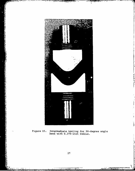
forming (although not with ultrasonic forming), and it wasdecided to use two-step forming to accomplish the requiredbend. A third set of tools was therefore made for the inter-mediate forming step. These tools, Figure 15, providedfor a radius of 0.375 inch and an included angle of 90 de-grees.
The tools were fabricated from H13 tool steel. Allpunches were designed with a #2 Morse taperlock attachmentto the reed in the ultrasonic system. All dies were likewisedesigned for taperlock attachment to the anvil. Figure11 shows one set of tools installed on the machine.
After fabrication and assembly, the equipment and toolingwere checked out by forming coupons of aluminum alloy tothe stated geometry. Satisfactory operation was established.
26
-4
Figure 15. Intermediate tooling for 90-degree anglebend with 0.375-inch radius.
27

EXPERIMENTAL INVESTIGATIONS
PRELIMINARY EXPERIMENTS
Using the equipment and tooling previously described,bending tests were conducted on 1.5 by 2.0 inch specimensof the 0.050-inch thick nickel 200. Both 45-degree and60-degree angle tools were used. Bending parameters werevaried from 800 to 3600 pounds static force, 0 to 3000 wattsultrasonic pcwer, and a dwell time of 1 second. Becauseof the low yield strength of the nickel (34,000 psi), well-formed parts without springback were readily obtained bothwith and without ultrasonic application.
The steel AM355-CRT, 0.040 inch thick, proved to bemuch more difficult to form because of its high yield strength(200,000 psi). Bends of 45 and 60 degrees were made with3600 pounds of static force, 2000 to 3000 watts power, and1 to 3 seconds dwell time, and with the tools oriented bothparallel and perpendicular to the transducer axis. Substantialspringback (5 to 10 degrees) occurred both with and withoutultrasonic application. The combined static and ultrasonicdynamic forces apparently were not sufficient to exceedthe yield strength of the steel.
The titanium 6AI-4V alloy, with an intermediate yieldstrength of 126,000 psi, presented a different problem.Without ultrasonic application and with a static force ofabout 2700 pounds, the material could not be formed to either45 or 60 degree angles. The specimens invariably crackedinto two pieces along the apex of the nose. The bend radiuswas apparently too sharp. No such cracking occurred whenultrasonics was applied during forming.
In an effort to determine the limits of forming thetitanium without ultransonics, the stroke of the punch waslimited, to produce a larger included angle. Table 3 showsthe results obtained with both ultrasonic and non-ultrasonicforming. All specimens were preformed without ultrasonicsto about a 125-degree angle (see Specimen T4). As notedin the table, attempts to form beyond the T4 angle withoutultrasonics invariably caused cracks (Specimens T6 throughT9), even when the forming was done in steps. For specimens"Tl, T2, T3, and TS, the ultrasonics was initiated at theinstant the ram punch contacted the material, and a singlestroke was used to seat the punch in the die. Under theseconditions, well-formed parts were obtained without cracks.Thus, with the titanium alloy, unlike the nickel or steel,ultrasonics obviously exerted a beneficial effect.
The behavior of the titanium alloy without ultrasonicstriggered the decision to fabricate tools for two-step forming.
28
)A

TABLE 3. PRELIMINARY BENDING OF TITANIUM SPECIMENS
Tooling: 6 0°Punch with 0.188-Inch Radius
Static Ultrasonic Dwell Included InsideSpecimen Force Power Time Angle Radius*
No. (ibs) (watts) (sec) (degrees) (inch) Connents
T1 2700 1400 1.0 70.0 0.109
T2 2700 1400 1.0 69.0 0.109
T3 2700 2200 1.0 70.5 0.109
T4 2700 0 0 125.2 0.125 Preform
TS 2700 1400 1.0 72.0 0.109
T6 2700 0 0 119.5 0.078 Cracked
T7 2700 0 0 99.0 0.109 Cracked
T8 2700 0 0 110.0 0.078 Cracked
T9 2700 0 0 168.0 0.093 Cracked
• To nearest 0.016 inch.
3 29

The intermediate tools (Figure 15) had an included angleof 90 degrees and a punch radius of 0.375 inch. With thetwo-step process, non-ultrasonic bending of the materialwas readily achieved.
PREPARATION OF EVALUATION SAMPLES
Evaluation samples of all three materials were preparedusing the two-step process in which the coupons were bentfirst to a 90-degree included angle and subsequently toeither 45 or 60 degrees. The selected parameters were 2400pounds static force, 4000 watts ultrasonic power, and usually1 second dwell time. A dwell time of 0.5 second was usedin the preforming of the nickel specimens. Non-ultrasonicsamples were also made using only 2400 pounds static force.
The numbers of each type of sample prepared were asfollows:
Included No. of SamplesMaterial Angle Ultrasonic Non-Ultrasonic
Nickel g0o 25 3450 5 2
Steel 600 24 3450 5 2
Titanium 600 23 3900 2 5
The included angles between the legs of all sampleswere measured, with the results shown in Table 4. As pre-viously observed, there was little difference between theultrasonic and non-ultrasonic samples of nickel. Essentiallyno spring-back occurred in either case. In the s~teel, thespringback was in the range of 4 to 6 degrees for the 60-degree specimens and in the range of 3 to 4.5 degrees forthe 45-degree specimens. The ultrasonic specimens exhibitedabout 2 percent less springback than those formed with staticforce alone. For the titanium alloy formed to 60 degrees,the springback ranged from 0.5 to 2.8 degrees for the ultra-sonic and from 2.5 to 3 degrees for the non-ultrasonic speci-mens.
Nose radii were also measured to the nearest 1/64 inch.For the 60-degree angle bends, the radii ranged from 3/32to 7/64 inch for the nickel, from 7/64 to 1/8 inch for thesteel, and were uniformly 7/64 inch for the titanium. Nosignificant difference between ultrasonic and non-ultrasonicspecimens was evident.
The specimens were well-formed and clean in the nosearea, and no cracks were visually observed in any of the
30

TABLE 4. INCLUDED ANGLES OF EVALUATION SAMPLES
Included Ultrasonic Individual IncludedAngle Power Angles Average
Material (degrees) (watts) (degrees) (degrees)
Nickel 60 4000 60, 61, 61, 61, 60.5, 60.560.2, 61, 61, 61, 60.5,60, 60.5, 61.1, 61, 60,60.5, 60.5, 60.2, 60.5,61, 60, 60.4, 60, 60,60, 60.1
60 0 59.9, 61, 61 60.645 4000 44.1, 44.9, 45, 44, 45 44.6
45 0 45.2, 45 45.1
Steel 60 4000 64, 64.2, 65, 65, 65, 64.864.5, 65, 65, 65, 65,65, 63.5, 64.5, 64.5,64.5, 65, 63.5, 66, 66,66, 64.4, 64.5, 64, 65
60 0 66, 66, 66 66.0
45 4000 43.9, 43.2, 43, 43.5, 43.343
45 0 44.4, 44 44.2
Titanium 90 4000 112, 112 112.0
90 0 113.8, 113.2, 113.8, 113.7114.3, 113.2
60 4000 60.5, 61.5, 61.3, 61, 61.6,61, 61.5, 61.2, 61.5,62, 62.5, 62.8, 61, 62,61.5, 62, 62, 62, 61,61.8, 61, 61.6, 61, 61.8
60 0 62.5, 62.8, 63 62.8
31

WVi
specimens. It should be noted that no lubricant was usedduring forming, and there was occasional die pickup fromthe sheet materials being formed. The punch and die werenot cleaned or polished between specimens, and the die pickupresulted in scuff marks and burn spots on some specimens.Hqwever, these imperfections always occurred on the outerlegs at some distance from the nose. The critical nosearea was always clean and smooth. Such die pickup wouldnot be a problem in dynamic forming where a lubricant wouldbe used during a drawbench operation,
HUGHES EVALUATION OF SAMPLES
Samples of 60-degree angle bends in all three materialswere sent to Hughes Helicopters for evaluation of dimensionalvariations, surface finish, and metallurgical changes.For each material, ten ultrasonic samples and three non-ultrasonic samples were evaluated. Comparisons were madewith specimens prepared by Hughes and bent to a 90-degreeangle using an air-forming process.
The results of the dimensional measurements are providedin Tables 5 and 6. The included angle measurements (Table 5)are approximately the same as those recorded in Table 4for the Sonobond measurements, and all materials showedthe same advantage of ultrasonic over statically formedS specimens in terms of reduced springback.
Measurements of nose radii by Hughes (Table 6) weremore precise than those conducted by Sonobond. The resultsshow that the ncse radii formed under ultrasonic activationwere sharper than those obtained with static force alone.
With regard to surface finish on the specimens, Hughesconcentrated its attention on the scuffs and burn markspreviously described. These were particularly severe onthe stainless 3teel, where it was noted that the insidesurface of the specimens showed both shallow and severe* deep burnt pits, areas surrounding the pits showed discolor-ation ranging from straw yellow to blue, and the outsidesurfaces opposite the deep pits showed straw yellow discolor-
- ation. It was further noted that the pits occurred at dis-tances ranging from 0.48 to 0.80 inch from the nose of thespecimen (see Table-7). The pits ranged in size from 0.03by 0.17 inch to 0.042 by 0.005 inch. Similar marks wereobserved on the titanium alloy specimens and, to a muchlesser extent, on the nickel specimens, although measure-ments such as those in Table 7 were not made on these twomaterials.
In contrast, the Hughes specimens air-formed to 90degrees showed no burnt pits and only slight surface scuffing
32
'A~

TABLE 5. INCLUDED ANGLE BETWEEN LEGS
(Measurements by Hughes)
Goal: 60.00 Ultrasonic, 900 Air Formed)
StandardForming Individual Angles Average Deviation
Material Process (degrees) (degrees) (degrees)
Steel Sonobond 65.4, 66.0, 66.3 65.9 0.5Non-Ultrasonic
Sonobond 64.8, 64.6, 64.9, 64.7 0.3Ultrasonic 64.5, 64.6, 64,
64.7, 64.9, 65, 65
Hughes 90.5, 90, 91, 90, 90.5 0.44Air Formed 90, 90, 91, 91,
90.5, 90.5
Titanium Sonobond 63, 63.3, 63.5 63.3 0.3Non-Ultrasonic
Sonobond 62.3, 63, 61.6, 61.8 0.7Ultrasonic 61.6, 61.2, 62, 61,
62.4, 61, 62
Hughes 91.5, 91, 91, 90.5, 90.4 0.57Air Formed 90, 90, 90, 90, 90,
90
Nickel Sonobond 60, 61.3, 61.3 60.9 0.8Non-Ultrasonic
Sonobond 60.4, 60.2, 60.3 60.6 0.4Ultrasonic 60.3, 61, 60.9, 61,
60.1, 60.5, 61
Hughes 92, 91.5, 90.5, 90.2 1.2Air Formed 90.5, 90.5, 87.5,
89.5, 90, 90
33

TABLE 6. HUGHES MEASUREMENTS OF NOSE RADII
Goal: 0.168 inch
StandardForming Individual Radii Average Deviation
Material Process (inch) (inch) (inch)
Steel Sonobond 0.152, 0.152 0.152 0Non-Ultrasonic 0.152
Sonobond 0.145, 0.145, 0.145 0Ultrasonic 0.145, 0.145,
0.145, 0.145,0.145, 0.146,0.145, 0.145
Hughes 0.168, 0.167, 0.165 0.002
Air Formed 0.164, 0.169,0.164, 0.162,0.166, 0.1640.166, 0.164
Titanium Sonobond 0.153, 0.155, 0.154Non-Ultrasonic 0.153
Sonobond 0.154, 0.153, 0.153 0.005Ultrasonic 0.155, 0.150,
0.154, 0.154,0.153, 0.155,0.152, 0.154
Hughes 0.174, 0.178, 0.174 0.002Air Formed 0.160, 0.180,
0.175, 0.173,0.176, 0.174,0.172, 0.179
Nickel Sonobond 0.152, 0.152 0.152 0Non-Ultrasonic 0.152
Sonobond 0.143, 0.147, 0.143 0.003Ultrasonic 0.144, 0.147,
0.144, 0.142,0.139, 0.139,0.144, 0.145
Hughes 0.163, 0.162, 0.161 0.002Air Formed 0.156, 0.161,
0.159, 0.164,0.161, 0.159,0.160, 0.160
34

TABLE 7. BURNT PIT DISTRIBUTION OF STAINLESS STEEL
No.Sample Pit Distance No. of Pit Size Range of Discolor-
No. from Nose Pits* (inches) Spots ation**
Si 0.57 -0.75 12 0.030 x 0.040 - Faint0.030 x 0.185
S2 0.55 - 0.65 9 0.03. J35 - Straw0.07 .6 yellow,
distinctive
S3 0.58 - 0.80 8 0.04 x 0.055 - 3 Straw0.08 x 0.125 yellow
S4 0.53 - 0.75 9 0.040 x 0.045 - 2 Straw0.07 x 0.150 yellow
S5 0.54 - 0.62 9 0.032 x 0.030 - 4 Straw0.07 x 0.140 yellow
S6 0.57 - 0.76 9 0.030 x 0.040 - 4 Straw0.06 x 0.150 yellow
S7 0.58 - 0.71 10 0.025 x 0.035 - 5 Straw0.06 x 0.130 yellow
S8 0.48 - 0.75 10 0.020 x 0.025 - 5 Straw0.09 x 0.170 yellow
S9 0.54 - 0.63 16 0.023 x0.030 - 0 Straw0.07 x 0.110 yellow
SI0 0.58 - 0.73 14 0.025 x 0.030 - 0 Straw0.03 x 0.16 yellow
* Pits on inside surface.
** Discoloration on outside surface opposite pl.ts.
35

at an area 1/4 inch from the nose.
Likewise the metallurgical examination by Hughes wasconcentrated on the burnt pits and not on the nose sectionof primary interest. Samples showing the burnt pits weremounted in bakelite and cross-sectioned for metallurgicalexamination. The hardness in the vicinity of the pit wasdetermined by microhardness measurements, and hairline cracksalong the periphery of the pits were examined by a ScanningElectron Microscopic (SEM) method.
It was noted that the ultrasonically formed stainlesssteel and titanium alloy showed cracks, structural changes,and changed mechanical properties. Tables 8-10 presentSthe results of these evaluations. In the stainless steelspecimens, photomicrographs in the vicinity of the pit showeda white zone which was interpreted as austenite, convertedfrom martensite and retained austenite. The titanium alloyshowed no apparent structural change, but the hardness readingsindicated some anomaly. Nickel showed little change instructure and hardness in the vicinity of the pits.
It should be emphasized that these surface finish andmetallurgical examinations performed by Fughes were conductedonly on the pitted areas on the legs of the specimens, remotefrom the nose areas. No such evaluation was made of thenose areas themselves, which were of primary importancein this investigation. As previously noted, the imperfec- Itions were due to die and punch pickup from the materialsbeing formed, and such pickup would not occur with a dynamiclubricated process for forming the nosecap sections. Con-sequently these Hughes observations were not germane tothe ultimate objectives of the program.
PREPARATION AND EVALUATION OF ADDITIONAL TITANIUM SAMPLES
Subsequent to the evaluations reported by Hughes Heli-copters, additional formed samples of the titanium alloywere prepared and forwarded to Hughes.
These samples were preformed to the 90-degree bendwith and without ultrasonic application and were subsequentlyformed to 60 degrees. Parameters were the same as previouslyused, except that the ultrasonic power level was reducedto 2000 watts. In an effort to eliminate the scuff marksand pitting which were of such concern to Hughes, for someof these specimens a thin Teflon rubber film was insertedbetween the specimens and the die during forming. Thisprovided the desired protection, and such samples were es-sentially free from the imperfections that characterizedthe earlier samples.
36

TABLE 8. HARDIESS NEAR PIT AREA,ULTRASONICALLY FORMED STEEL
Distance fromBottom of Pit Hardness
* (inch) (R) Comments
0.002 34.7 Retained austenite
(white zone)
0.004 38.2 Retained austenite
0.006 40.8 Heat-affected zone
0.008 41.3 Heat-affected zone
0.010 43.7 Heat-affected zone
0.012 46.4 Heat-affected zone
0.014 46.4 Heat-affected zone
0.016 45.0 Heat-affected zone
0.018 45.3 Heat-affected zone
0.022 43.7 Heat-affected zone
0.026 46.4 Heat-affected zone
Away from 46.1i)Awt from 46.1) Av. Martensite andPit Core 46.) 46.4 Retained austenite
46 .9)
Dimensions Depth 0.007 inchof Pit Length 0.050 inch,
maximum
37
7 jýT !
TABLE 9. HARDNESS NEAR PIT AREA,ULTRASONICALLY FORMED TITANIUM
Distance fromBottom of Pit Hardness
(inch) (R C) Comments
0.002 33.5 Alpha and Beta
0.004 36.3 Alpha and Beta
0.006 34.1 Alpha and Beta
0.008 34.9 Alpha and Beta
0.010 37.1 Alpha and Beta
0.012 34.4 Alpha and Beta
0.014 33.5 Alpha and Beta
0.016 34.1 Alpha and Beta
0.018 34.7 Alpha and Beta
0.020 36.6 Alpha and Beta
0.022 37.4 Alpha and Beta
0.024 34.7 Alpha and Beta
0.026 37.1 Alpha and Beta
Away from 33.5) Av.Pit Core 36.1)
34.7) 34.8
Dimensions Depth 0.006 inchof Pit Length 0.043 inch,
maximum
38

TABLE 10. HARDNESS NEAR PIT AREA,ULTRASONICALLY FORMED NICKEL
S~Distance fromBottom of Pit Hardness
(inch) (Rb) Comments
0.002 63.8 No microstructural change
0.006 71.1 No microstructural change
0.010 70.1 No microstructural change
0.014 65.5 No microstructur!1 change
0.018 66.3 No microstructural change
0.022 65.5 No microstructural change
0.026 67.3 No microstructural change
Away from 65.5)Pit Core 67.3) Av.
72.1) 68.3
Dimensions Depth 0.005 inchof Pit Length 0.045 inch,
maximum
39

The results of the Hughes evaluation of these additionalsamples are provided in Table 11.
40

TABLE 11. ADDITIONAL SAMPLES OF TITANIUM 6A1-4VALLOY EXAMINED
All samples preformed to 90 degrees and subsequentlyformed to 60 degrees.
Sample No. ofNo. Pieces Process Results
1 3 Non-ultrasonic to 90 . Outside surface scuffedslightly.
2 7 Non-ultrasonic to 900, Outside surface scuffed.then ultrasonic to One piece broke into600. halves. Two pieces
cracked over entire nosearea. Three pieces hadsmall cracks and orangepeel. Included angle63.5
3 2 Ultrasonical~y pre- Outside surface scuffedformed to 90. slightly.
04 6 Preformed to 90°, then Burnt pit shallower thanultragonically formed before on inside surface.to 60 , 2000 watts, Tiny cracks. 0 Included2400 lbs, I sec dwell, angles 61-64 , nose
radius 0.145".
5 1 Preformed to 90 , then Numerous small noseultragonically formed cracks. No scuff marks.to 60 , 2000 watts, Nose radius 0.150".2400 lbs, 1 sec dwell.Used thin Teflon rubberfilm between titaniumand die.
6 2 Same as above. Outside surface scuffmarks barely visiblS.Included angle 78.2Nose radius 0.148".
7 2 Same as above. Outside surface scuffmarks barely visible.Burnt pit and cracksnear nose, inside s 8 rface.Included angle 78.3Nose radii 0.150" , 0.151".
41

ULTRASONIC DYNAMIC FORMING EQUIPMENT
The experimentation previously described was orientedto static forming of small coupons of the materials of interest.The ultimate objective of the program was a dynamic systemthat would form extended lengths of the materials to therequired nosecap contour.
For this purpose, it was decided to use an ultrasonicallyactivated drawbench, sinch ultrasonic tube drawing had provento be eminently effective for production applications.The nosecap forming would not be significantly differentfrom tube drawing except that the final configuration wouldbe open rather than a closed tube. An ultrasonic systemsuch as that designed for static forming (Figure 9) couldbe mounted on the drawbench, and the material to be formedcould be drawn through the punch and die set. As previouslynoted, the materials of interest, and particularly the titaniumalloy, could be ultrasonically drawn in a single-step processto the required configuration.
With this arrangement in mind, drawbench specifications,delineated in Table 12, were forwarded to a number of drawbenchmanufacturers to determine if they could provide a drawbenchsuitable for this application. Specific interest was expressedby three drawbench manufacturers:
1. All American Engineering CompanyBox 1247801 South Madison StreetWilmington, Delaware 19899
2. The Fenn Manufacturing Company200 Fenn RoadNewington, Connecticut 06110
3. Witloe Associates, Inc.Noble RoadAtglen. Pennsylvania 19310
These firms were investigated by personal visits to theirfacilities and appraisal of their capabilities.
All American Industries had only a basic knowledgeof drawbenches and did not display the proficiency necessaryto produce the required drawbench. Their method of grippingwas unsatisfactory, since they intended to drill a holein the draw material, place a bar through the hole, andpull the bar. This would inouce indeterminable stress onthe draw material which could eventually lead to fracture.This and other factors led to the rejection of this sourcefor the drawbench.
42

TABLE 12. SPECIFICATION FOR AN ULTRASONIC DRAWBENCH
i. Purpose. This requirement is based on the need for a meansto cold-form materials in the shape of a helicopter rotorblade nosecap. The specific requirement is for the nosecapLon the Hughes AH-64 Armed Attack Helicopter.
2. Materials. The materials to be drawn include:
a. Titanium 6A1-4V Alloyb. Nickelc. AM355-CRT Stainless Steel.
3. Dimensions. The preforms are a maximum of 28 feet in lengthto a minimum of 6 feet in length; material thickness 0.050inch- the preform is 12 inches on the arc. Note: Sufficientmaterial must be provided at the drawing end to accommodatedrawing grips.
A 5-foot tooling area to accommodate the ultrasonic headmust be provided. Sonobond will supply mounting detailsfor the ultrasonically activated dies.
4. Feed. Ball screw feed is required at a maximum of 8 feetper minute; smooth linear feed is required.
5. Draw Force. The bench must be designed for a maximum drawforce of 20,000 pounds. Frame must be capable of withstandingall draw forces.
6. Lubrication. Automatic lubrication ahead of the ultrasonicdies is required.
7. Clearance. The ultrasonic anvil will fit inside the nosecapard since the anvil will be mounted on the drawbench, suffi-cient clearance must be provided to avoid interference withthe preform as it moves along the drawbench. A schematic ofthe side view o0 the ultrasonic head is provided.
8. Power. Sufficient power of a suitable source must be pro-vided to generate the draw force as indicated above.
9. Interlock. Drawbench controls must be interlocked with theultrasonic controls such that movement of the preform throughthe ultrasonic dies is accompanied by ultrasonic activation.
43C,

Witloe Associates had never built a drawbench but hadrebuilt and repaired machinery including drawbenches. Itwas felt that the requirements for rebuilding may be morestringent than building a system from the outset, sincenew components must be assembled to existing parts. Witloeproposed to use a caliper jaw to grip the specimen to bedrawn.
Fenn Manufacturing Company had a first-class machinefabrication facility, had fabricated drawbenches, and appearedto be qualified to produce the required equipment. Theywere not familiar with titanium and were not sure how theywould grip it for the draw. They also did not indicatehow they would support the draw screw. Eventually theysubmitted the specifications provided in Table 13, whichappeared to fulfill the requirements for ultrasonic dynamicforming. This facility was therefore selected to providethe required drawbench.
Since this program was suspended before the dynamicforming phase could be undertaken, no further action wastaken on procurement and assembly of the dynamic system.
"44
-4!

TABLE 13. SPECIFICATIONS FOR 20,000-POUND BALL SCREWDRAWBENCH COMPLETE WITH ACCESSORIES
Prepared by The Fenn Manufacturing Company,Newington, Connecticut
GENERAL DATA
Type of Equipment Drawbench - Ball Screw Type
Speed 1 to 8 feet per minute
Maximum Entry Size 6-inch Diameter Tube
Materials Titanium, Nickel, and StainlessSteel
Maximum Speed - Pusher 8 feet per minute
Minimum Speed - Pusher 1 foot per minute
Maximum Speed - Puller 8 feet per minute
Minimum Speed - Puller I foot per minute
Minimum Preform Length 6 feet
Maximum Preform Length 28 feet
Maximum Draw 30 feet
Draw Pull (Maximum) 20,000 pounds.
DESCRIPTION OF EQUIPMENT
ITEM 1
One (1) 20,000-pound Pull Drawbench utilizing a ball screwarrangement to obtain a smooth linear pull. The frame of thisunit is made of rigid heavy-duty boiler plate. The puller ismounted on precision roller bearings so as to form a trolley.The trolley is contained between retaining gibs and the frameunit which has a minimum running clearance. This assures gooduniform action in the ball and screw assembly.
A 5-foot space is provided in the center of the bench, and inthe event of an order, Sonobond will provide Fenn with mountingdetails for the ultrasonic die unit. The movable gripper jawunit will be provided with one (i) set of jaws to customer'srequirements.
45

TABLE 13 (Concluded)
An automatic jaw-opening actuator is provided on the pullingside of the bench and is adjustable along its length to accom-modate varying lengths of after-forms. When the end of thepreform passes through the die, a pair of rollers on thegripper unit strikes the actuator and opens the gripper jaws,allowing the after-form to be removed.
ITEM 2
One (1) 20,000-pound Push Form Unit is on a plate which can berelocated into several locations (several sets of holes will beprovided for this purpose). A plate will be provided with pre-form shape in it. With this unit the forming dies can be intheir working position while the preform is pushed throughsufficiently so it can be picked up by the gripper on the otherside of the die. The maximum push stroke will be 3 feet.
ITEM 3
Variable Speed Drive Units for both the pusher and puller willgive a speed range of 1 to 8 feet per minute in both the forwardand reverse directions. Both the puller ball screw and the pusherball screw are driven separately by their own drive motor. Therewill be one power unit supplying both drive motors so only onecan be run at any one time.
46

CONCLUSIONS AND RECOMMENDATIONS
1. The forming of titanium alloy can definitely bebenefited with ultrasonic application. Ultrasonicforming to the required 0.168-inch radius, 60-degreeangle configuration of a helicopter rotor blade nosecap can be accomplished in a one-step process, whereaspreforming of this material is necessary to avoid crack-ing with static force application alone.
2. Ultrasonically assi*sted forming offers no significantbenefits in the formina of nickel 200 sheet material.The yield strength of the material is low enough thatforming to the required configuration can be achievedwith static forming alone without ultrasonic application.
3. Ultrasonic forming of a high-strength stainless steelsuch as AM355-CRT offered no significant benefits overstatic forming because the combined static and dynamicforces were not sufficient to overcoire the yield strengthof this material at the available 4000-watt ultrasonicpower level. Higher ultrasonic powers would be requiredto achieve significant benefits with this high-yield-strength material.
4. The scuffing and burnt pits on the ultrasonically formedsurfaces as evaluated by Hughes Helicopters all occurredoutside the critical nose radius and were attributedto die and punch pickup from the materials being formed,which were not renmved between formings. Such diepickup would not be encountered with a lubricated dynamicsystem for forming the nosecaps.
5. Dynamic ultrasonic forming to the nosecap configurationusing an ultrasonic system mounted on an appropriatelydesigned drawbench appears to be feasible.
6. It is recommended that ultrasonic forming of titaniumalloy be considered for other applications involvingthe forming of this material for aircraft surfaces.
47

DISTRIBUTION LIST
No. ofCopies To
Comnu-ndar, U.S. Army Aviation Research and Development Command,4300 Goodfellow Boulavard, St. Louis, Missouri 6321)
10 ATTN: DRDAV-EGXI DRDAV-D1 DRDAV-N
Project Manager, Advanced Attack Helicopter, P.O. Box 209,St. Louis, Missouri 63166
2 ATTN: DRCPM-AAH-TM1 DRCPM5-AAH-TP
Project Manager, Black Hawk, P.O. Box 209, St. Louis, Missouri 631662 ATTN: DRCPM-BH-T
Project Manager, CH-47 Modernization, P.O. Box 209, St. Louis, Missouri 631662 A7rN: DRCPM-CH-47-MT
Project Manager, Aircraft Survivability Equipment, P.O. Box 209,St. Louis, Missouri 63166
2 ATTN: DRCPM-ASE-TM
Project Manager, Cobra, P.O. Box 209, St. Louis, Missouri 631662 ATTN: DRCPM-CO-T
Project Manager, Advanced Scout Helicopter, P.O. Box 269,St. Louis, Missouri 631662 ATTN: DRCPM-ASH
Project Manager, Navigation/Control Systems, Fert Monmouth, New Jersey 077032 ATN: DRCPM-NC-TM
Project Manager, Tactical Airborne Remqtely-Piloted Vehicle/Drone Systems,P.O. Box 209, St. Louis, Missouri 63166
2 ATTN: DRCPM-RPV
Commander, U.S. Army Matariel De.velopment and Readiness Command,5001 Eisenhower Avenue, Alexandria, Virginia 22333
4 ATTN: DRCMT2 DRCPM
Director, Applied Technology Laboratory, Research and TechnologyLaboratories (AVRADCOM), Fort Eustis, Virginia 23604
2 ATTN: DAVDL-ATL-ATS
Director, Research and Technology Laboratories (AVRADCOM), Moffett Field,California 94035
2 ATTN: DAVDL-AL-D

No. of
Copies To
Director, Langley Directorate, U.S. Army Air Mobility Rosearch andDevelopment Laboratories (AVRADCOM), Hampton, Virginia 23365
2 ATrN: DAVDL-LA, Mail Stop 266
Comnander, U.S. Army Avionics Research and Development Activity,Fort Monmouth, New Jersey 07703
2 ATTN: DAVAA-0O'
Director, Lewis Directorate, U.S. Army Air Mobility Rasearch andDevelopment Laboratories, 21000 Brookpark Road, Cleveland, Ohio 44135
2 ATTN: DAVDL-LE
Director, U.S. Army Industrial Base Engiriing Activity,Rock Island Arsenal, Rock Island, Illinois 61299
4 ATrN: DRXIB-MI
Commander, U.S. Army Troop Support and Aviation Materiel Readiness Command,4300 Goodfellow Boulevard, St. Louis, Missouri 63120
1 ATTN: DRSTS-PLC1 DRSTS-ME2 DRSTS-DIL
Office of the Under Secretary of Defense for Research and Engineering,The Pentagon, Washington, D.C. 20301
1 ATTN: Dr. L. L. Lehn, Room 3D 1079
12 Commandor, Defense Technical Information Center, Cameron Station,Alexandria, Virginia 22314
Defense Industrial Resources Office, DIRSO, Dwyer Building, Cameron Station,Alexandria, Virginia 22314
1 ATTN: Mr. C. P. Downer
Headqvarters, Department of the Army, Washington, D.C. 203102 ATTN: DAMA-CSS, Dr. J. Bryant1 DAMA-PPP, Mr. R. Vawtor
Director, Defense Advanced Research Projects Agency, 1400 Wilson Boulevard,Arlington, Virginia 22209
1 ATTN: Dr. A. Beament
Commander, U.S. Army Missile Command, Redstone Arsenal, Alabama 35809I ATMN: DRSMI-ET1 DRSMI-RBLD, Redstone Scientific Information CenterI DRSMI-NSS
Commander, U.S. Army Tank-Automotive Research and Development Command,Warren, Michigan 48090
1 ATTN: DRDTA-RI DRDTA-RCIa, LVr. J. ChevalierI Technical Library
-I
No. ofCopies To
Commander, U.S. Army Tunk-Automotzve Materiel Readiness 'ýo'mand,Warren, Michigan 48090
1 ATTN: DrSTA-EB
Commander, U.S. Axay Armament Research vad Oevelopment Command,Dover, New Jersey 07801
I ATTN: DRVAR-PML1 Technical Library1 Mr. Harry E. Pebly, Jr., PLASTEC, Director
Commander, U.S. Army Armament Research and Development Command,Watervliet, New York 12189
I AT'N: DRDAR-LAB-S1 SARNV-PPI
Commander, U.S. Army Armament Materiel Readiness Command,Rock Island, Illinois 61299
1 ATTN: DRSAR-IRB1 DRSAR-IMCI Technical Library
Commander, U.S. Army Foreign Science and Technology Center,220 7th Street, N.E., Charlottesville, Virginia 22901
I ATTN: DRXST-SD3
Commander, U.S. Army Electronics Research and Development Command,Fort Monmouth, New Jersey 07703
1 ATTN: DELET-DS
Commapder, U.S. Army Electronics Research and Development Command,2800 Powder Mill Road, Adelphi, Maryland 20783
1 ATTN: DRDEL-BC
Commander, U.S. Army Depot Systems Command, Chambersourg,Pennsylvania 37201
1 ATTN: DRSDS-PMI
Commander, U.S. Army Test and Evaluation Caompni, Aberdeen Proving Ground,Maryland 21005
1 ATTN: DRSTE-ME
Commander, U.S. Army Comau.nications and Ele-ýtronics Materiel ReadinessCommand, Port Monmoit*., New Jersey 07703
1 ATTN: DRSEL-LE-R
Commander, U.S. A.ml C.immunications Rosearch and Developmant Command,Fort Monmouth, Neu Jersey 07703
1 ATrN: DRDCO-PPA-lP
No. ofCopies To
Director, U.S. Army Ballistic Research Laboratory, Aberdeen Proving Ground,Maryland 21005ATrr: DRDAR-TSB-S (STINFO)
Chief of Naval Research, Arlington. Vfrginia 222171 ATTN: Code 472
Headquarters, Naval Material Command, Washington, D.C. 203601 ATTN: Code MAT-042M
Headquarters, Naval Air Systems Command, Washington, D.C. 203611 AMTN: Code 5203
I Headuuarters, Naval Sea Systems Command. 1941 Jefferson Davis Highway,Arlington, Virginia 22376
1 AMTN: Code 035-- •iHeadquarters, Naval Electronics Systems Command, Washington, D.C. 20360
1 ATTN: Code 504
Director, Naval Material Command, Industrial Resources Detachment,Ibuilding 75-2, Naval Base, Philadelphia, Pennsylvania 19112
1 ATTN: Technical Director
Commander, US. Air Force Wright Aeronautical Laboratories, Wright-PattersonAir Force Base, Ohio 45433
I1 ATTN: AFWAL/MLTN
1. A.FWAL/ML7M1 AFWAL/MLTE1 AFWAL/MLTC
National Aeronautics and Space Administration, Washington, D.C. 20S461 ATTN: AFSS-AD, Office of Scientific and Technical Information
National Aeronautics and Space Administration, Marshall Space FlightCenter, Huntsville, Alabama 35812
1 ATTN: R. J. Schwinghammer, EHO1, Dir., M&P Labi Mr. W. A. Wilson, EH41, Bldg. 4612
2 Meta's and Ceramics Information Center, Battelle Columbus Laboratories,505 King Avenue, Columbus, Ohio 43201
Hughes Helicopters-Summa, M/S T-419, Centinella Avenue and Teale Street,Culver City, California 90230
2 AT•rN: Mr. R. E. Moore, Bldg. 314
Sikorsky Aircraft Division, United Aircraft Corporation, Stratford,Connecticut 06497
2 ATN: Mr. Melvin M. Schwartz, Chief, Manufacturing Technology

Ii '7
No. ofCopies To
Bell Helicopter Textron, Division of Textron, Inc., P.O. Box 482,Fort Worth, Texas 76101
2 ATTN: Mr. P. Baumgartner, Chief, Manufacturing Technology
Kaman Aerospace Corporation, Bloomfield, Connecticut 060022 ATTN: Mr. A. S. Falcone, Chief, Materials Engineering
Boeing Vertol Company, Box 16858, Philadelphia, Pennsylvania 191422 ATTN: R. Pinckney, Manufacturing Technology2 R. Drago, Advanced Drive Systems Technology
V Detroit Diesel Allison Division, General Motors Corporation, P.O. Box 894,Indianapolis, Indiana 46206
2 ATTN: James E. Knott, General Manager
General Flectric Company, 10449 St. Charles Rock Road, St. Ann,Missouri 63074
2 ATN: Mr. H. Franzen
AVCO-Lycoming Corporation, 550 South Main Street, Stratford,Connecticut 08497
2 ATTN: Mr. V. Strautman, Manager, Process Technology Laboratory
United Technologies Corporation, Pratt & Whitney Aircraft Division,Manufacturing Research and Development, East Hartford, Connecticut 06108
2 ATTN: Mr. Ray Traynor
Grumman Aerospace Corporation, Plant 2, Bethpage, New York 117142 ATrN: Richard Cyphers, Manager, Manufacturing Technology2 Albert Grenci, Manufacturing Engineer, Department 231
Lockheed Missiles and Space Company, Inc., Manufacturing Research,1111 Lockheed Way, Sunnyvale, California 94088
2 ATTN: H. Dorfman, Research Specialist
Lockheed Missiles and Space Company, Inc., P.O. Box 504, Sunnyvale,
California 940862 ATTN: D. M. Schwartz, Dept. 55-10, Bldg. 572
Director, Army Materials and Mechanics Research Center,Watertown, Massachusetts 02172
2 ATTN: DRXMR-PLI DRXMR-PR1 DRXMR-PDI DRXMR-AP2 DRXMR-PMr
6 DRXNR-ER, Mr. A. M. Ayvazian
-------- ------------------------- i
4-I
- C 35 IL
A - - -- -Im t.3
, I'++ ,, U+ +°i
A r.x Is
- I- '- -I --
SU I tI+- - + + -• + ., + ! i+. + g}+ i
SI +J II II
--+ + g+ Ij1 'I+ .+ <: +, I, •I+ +: + ' +
!!i + f! +iIi!I-~ jil i! +