Embed Size (px)
Citation preview

One Technology Way, P.O. Box 9106, Norwood. MA 02062-9106, U.S.A.Tel: 617/329-4700 Fax: 617/326-8703
REV. 0
Information furnished by Analog Devices is believed to be accurate andreliable. However, no responsibility is assumed by Analog Devices for itsuse, nor for any infringements of patents or other rights of third partieswhich may result from its use. No license is granted by implication orotherwise under any patent or patent rights of Analog Devices.
a Evaluation Board for SimultaneousSampling, Dual 250 ksps 12-Bit ADC
EVAL-AD7862CBFEATURES
Full-Featured Evaluation Board for the AD7862
EVAL-CONTROL BOARD Compatible
Stand Alone Capability
On-Board Analog Buffers and Reference
Various Linking Options
PC Software for Control and Data Analysis when usedwith EVAL-CONTROL BOARD
Single Evaluation Board for AD7862-3 & AD7862-10
or +3V ultra high precision bandgap reference and an AD713quad op-amp used to buffer the four analog inputs. There arevarious link options which are explained in detail on page 2.
Interfacing to this board is through a 96-way connector. This 96-way connector is compatible with the EVAL-CONTROL BOARDwhich is also available from Analog Devices. External sockets areprovided for the CONVST input, A0 input, VREF input/outputand the four Analog inputs, VA1, VA2, VB1 and VB2.
OPERATING THE AD7862 EVALUATION BOARD
Power SuppliesWhen using this evaluation board with the EVAL-CONTROLBOARD all supplies are provided from the EVAL-CONTROLBOARD through the 96 way connector.
When using the board as a stand alone unit external supplies mustbe provided. This evaluation board has four power supply inputs:+5V, AGND, +15V and -15V. +5V is used to supply the AD7862and the 74HC245s bi-directional buffers. +15V and -15V are usedto supply the AD780 voltage reference and the AD713 quad op-amp. The AGND input is connected to the AGND plane.
The supplies are decoupled to AGND with 47µF tantalum and0.1µF ceramic disc capacitors at the point where they arrive on theeval board. The supply pins of each analog device are alsodecoupled to AGND with 10µF tantalum and a 0.1µF ceramiccapacitor.
Extensive ground planes are used on this board to minimize theeffect of high frequency noise interference. There are two groundplanes, AGND and DGND. These are connected at one locationunder the AD7862.
INTRODUCTIONThis Application Note describes the evaluation board for theAD7862 dual 12-Bit A/D converter. The AD7862 is a high speed,low power, dual channel 12-bit A/D converter that operates froma single +5V supply. The part contains two 4µs successive approxi-mation ADCs,two track/hold amplifiers, an internal +2.5V refer-ence and a high speed parallel interface. Full data on the A�D7862is available in the AD7862 data sheet available from AnalogDevices and should be consulted in conjunction with this Appli-cation Note when using the Evaluation Board.
The board is supplied with two versions of the AD7862. These arethe AD7862-3 which is inserted in the U1 position on the boardand the AD7862-10 which is in the antistatic box supplied with theevaluation board package. Either part can be evaluated by carefullyremoving the part on the board and inserting the other part.
On-board components include an AD780 pin programmable +2.5V
FIG. 1: FUNCTIONAL BLOCK DIAGRAM
Analog Inputs
Input Buffers
AD 78 62ADC
Buff ers
AD7 80Vo lt ageRe fer en ce
VA1
VA2
VB1
VB2
96 wayCo nne c tor
+15V -15V +5v Agnd

EVAL-AD7862CB
�2� REV. 0
Link and Switch Options
There are fourteen link options which must be set for the required operating setup before using the evaluation board. The functionsof these options are outlined below.
Link No. Function.
LK1 This link option is used to either ground the input to the VA1 analog buffer or connect it to the VA1 inputsocket.With this link position A, the VA1 input socket is connected to the VA1 analog buffer.With this link position B, the input to the VA1 analog buffer is connected to AGND.
LK2 This link option is used to either ground the input to the VB1 analog buffer or connect it to the VB1 inputsocket.With this link position A, the VB1 input socket is connected to the VB1 analog buffer.With this link position B, the input to the VB1 analog buffer is connected to AGND.
LK3 This link option is used to either ground the input to the VA2 analog buffer or connect it to the VA2 inputsocket.With this link position A, the VA2 input socket is connected to the VA2 analog buffer.With this link position B, the input to the VA2 analog buffer is connected to AGND.
LK4 This link option is used to either ground the input to the VB2 analog buffer or connect it to the VB2 inputsocket.With this link position A, the VB2 input socket is connected to the VB2 analog buffer.With this link position B, the input to the VB2 analog buffer is connected to AGND.
LK5 This link option is used to select the source of the positive supply for the AD780 and the AD713.In position A, the positive supply is connected to the +5V VDD line.In position B, the positive supply must be supplied via the external connector, J3.In position C, the positive supply is supplied by the EVAL-CONTROL BOARD.
LK6 This link option is used to select the source of the negative supply for the AD713.In position A, the negative supply pin is connected to AGND.In position B, the negative supply must be supplied via the external connector, J3.In position C, the negative supply is supplied by the EVAL-CONTROL BOARD.
LK7 This link option selects a 2.5V or 3.0V reference from the AD780. This link is permanently "OUT" whenevaluating the AD7862. This selects a 2.5V reference from the AD780.
LK8 This link option is used to select between the internal reference on the ADC or the on-board reference.With this link "IN" the 2.5V reference generated by the AD780 is selected.With this link "OUT", the ADC uses its internal reference.
LK9 This link option is used to select an external reference supplied via the external VREF socket (SMB1).With this link "IN" an external reference can be supplied via SMB1.
LK10 This link option is used to select the source of the VDD supply for the AD7862 and the digital buffers.With this link "IN" VDD is supplied by the EVAL-CONTROL BOARD.With this link "OUT" VDD must be supplied from an external source through the power connector, J2.
LK11 This link option selects the source of the CONVST input.With this link "IN" CONVST is supplied by the EVAL-CONTROL BOARD.With this link "OUT" CONVST must be supplied from an external source via SMB2.
LK12 This link option controls the input to the A0 pin of the AD7862.In position A, the A0 input is controlled by the EVAL-CONTROL BOARD.In position B, the A0 pin is controlled externally via SMB3.In position C, the A0 pin is connected to VDD.In position D, the A0 pin is connected to Agnd.
LK13,LK14 These link options are permanently "IN" when evaluating the AD7862. They connect the inputs of theunused digital buffers to Dgnd.

EVAL-AD7862CB
REV. 0 �3�
SET-UP CONDITIONSCare should be taken before applying power and signals to the evaluation board to ensure that all link positions are as per therequired operating mode. Table I shows the position in which all the links are set when the evaluation board is sent out.
Table I. Initial Link and Switch Positions
Link No. Position Function.
LK1 A VA1 analog input is connected to it's Analog input buffer.
LK2 B The input to the VB1 analog buffer is conncted to AGND.
LK3 A VA2 analog input is connected to it's Analog input buffer.
LK4 B The input to the VB2 analog buffer is conncted to AGND.
LK5 C The positive supply for the analog circuitry is supplied by the EVAL CONTROL BOARD
LK6 C The negative supply for the analog circuitry is supplied by the EVAL CONTROL BOARD
LK7 OUT The AD780 generates a 2.5V reference.
LK8 IN The 2.5V reference generated by the AD780 is applied to the AD7862 VREF pin.
LK9 OUT The external VREF socket is not used.
LK10 IN VDD for the ADC and the digital buffers is supplied by the EVAL CONTROL BOARD
LK11 IN CONVST is supplied by the EVAL-CONTROL BOARD.
LK12 A A0 is controlled by the EVAL-CONTROL BOARD.
LK13 IN Unused digital buffer input is connected to DGND.
LK14 IN Unused digital buffer input is connected to DGND.
EVAL-AD7862CB
�4� REV. 0
Table II. 96-Way Connector Pin Functions.
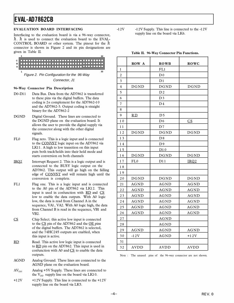
EVALUATION BOARD INTERFACING
Interfacing to the evaluation board is via a 96-way connector,J1. J1 is used to connect the evaluation board to the EVAL-CONTROL BOARD or other system. The pinout for the J1connector is shown in Figure 2 and its pin designations aregiven in Table II.
Figure 2. Pin Configuration for the 96-Way
Connector, J1
96-Way Connector Pin Description
D0-D11 Data Bus. Data from the AD7862 is transferredto these pins via the digital buffers. The datacoding is 2's complement for the AD7862-10and the AD7862-3. Output coding is straightbinary for the AD7862-2
DGND Digital Ground. These lines are connected tothe DGND plane on the evaluation board. Itallows the user to provide the digital supply viathe connector along with the other digitalsignals.
FL0 Flag zero. This is a logic input and is connectedto the CONVST logic input on the AD7862 viaLK11. A high to low transition on this inputputs both track/holds into their hold mode andstarts conversion on both channels
IRQ2 Interrupt Request 2. This is a logic output and isconnected to the BUSY logic output on theAD7862. This output will go high on the fallingedge of CONVST and will remain high until theconversion is complete.
FL1 Flag one. This is a logic input and is connectedto the A0 pin of the AD7862 via LK12. Thisinput is used in conjunction with RD and CSlow to enable the data outputs. With A0 logiclow, the data is read from Channel A in thesequence, VA1, VA2. With A0 logic high, the datafrom Channel B is read in the sequence, VB1 andVB2.
CS Chip Select. this active low input is connectedto the CS pin of the AD7862 and the OE pinsof the digital buffers. The AD7862 is selected,and the 74HC245 outputs are enabled, whenthis input is active.
RD Read. This active low logic input is connectedto RD pin on the AD7862. This input is used inconjunction with A0 and CS to enable the dataoutputs.
AGND Analog Ground. These lines are connected to theAGND plane on the evaluation board.
AVDD Analog +5V Supply. These lines are connected tothe VDD supply line on the board via LK10.
+12V +12V Supply. This line is connected to the +12Vsupply line on the board via LK5.
ROW A ROWB ROWC
1 FL1
2 D 0
3 D 1
4 DGND DGND DGND
5 D 2
6 D 3
7 D 4
8
9 R D D 5
10 D 6 CS
11 D 7
12 DGND DGND DGND
13 D 8
14 D 9
15 D10
16 DGND DGND DGND
17 FL0 D11 IRQ2
18
19
20 DGND DGND DGND
21 AGND AGND AGND
22 AGND AGND AGND
23 AGND AGND AGND
24 AGND AGND AGND
25 AGND AGND AGND
26 AGND AGND AGND
27 AGND
28 AGND
29 AGND AGND AGND
30 -12V AGND +12V
31
32 AVDD AVDD AVDD
Note : The unused pins of the 96-way connector are not shown.
-12V -12V Supply. This line is connected to the -12Vsupply line on the board via LK6.
1 32
1 32
ABC

EVAL-AD7862CB
REV. 0 �5�
SOCKETS
There are seven input sockets relevant to the operation of theAD7862 on this evaluation board. The function of these sockets isoutlined in Table III.
Table III. Socket Functions
Socket Function
SMB1 Sub-Miniature BNC Socket for external VREF.
SMB2 Sub-Miniature BNC Socket for CONVST input.
SMB3 Sub-Miniature BNC Socket for A0 input.
VA1 Sub-Miniature BNC Socket for VA1 input.
VA2 Sub-Miniature BNC Socket for VA2 input.
VB1 Sub-Miniature BNC Socket for VB1 input.
VB2 Sub-Miniature BNC Socket for VB2 input.
CONNECTORS
There are three connectors on the AD7862 evaluation board asoutlined in Table IV.
TABLE IV. CONNECTOR FUNCTIONS
Connector Function
J1 96-Way Connector for Parallel Interfaceconnections.
J2 External +5V & AGND power connector.
J3 External +15V & -15V power connector.
OPERATING WITH THE EVAL-CONTROL BOARD
The evaluation board can be operated in a stand-alone mode oroperated in conjunction with the EVAL-CONTROL BOARD.This EVAL-CONTROL BOARD is available from Analog De-vices under the order entry "EVAL-CONTROL BOARD". Whenoperated with this control board, all supplies and control signals foroperating the AD7862 are provided by the EVAL-CONTROLBOARD when it is run under control of the AD7862 softwarewhich is provided with the AD7862 evaluation board package.This EVAL-CONTROL BOARD will also operate with all AnalogDevices evaluation boards which end with the letters CB in theirtitle.
The 96-way connector on the EVAL-AD7862CB plugs directlyinto the 96-way connector on the EVAL-CONTROL BOARD.No power supplies are required in the system. The EVAL-CON-TROL BOARD generates all the required supplies for itself and theEVAL-AD7862CB. The EVAL-CONTROL BOARD is poweredfrom a 12V ac transformer. This is a standard 12V ac transformercapable of supplying 1A current and is available as an accessoryfrom Analog Devices under the following part numbers:
EVAL-110VAC-US: For use in the U.S. or Japan
EVAL-220VAC-UK: For use in the U.K.
EVAL-220VAC-EU: For use in Europe
These transformers are also available for other suppliers includingDigikey (U.S.) and Campbell Collins (U.K.).
Connection between the EVAL-CONTROL BOARD and theserial port of a PC is via a standard RS-232 cable which is providedas part the EVAL-CONTROL BOARD package. Please refer tothe manual which accompanies the EVAL-CONTROL BOARDfor more details on the EVAL-CONTROL BOARD package.

EVAL-AD7862CB
�6� REV. 0
Figure 3. FFT Screen
SOFTWARE DESCRIPTIONIncluded in the EVAL-AD7862CB evaluation board package is aPC-compatible disk which contains software for controlling andevaluating the performance of the AD7862 when it is operatedwith the EVAL-CONTROL BOARD. The EVAL-AD7862CBDemonstration/Evaluation Software runs under DOS 4.0 or laterand requires a minimum of a 386-based machine with 400kB ofbase RAM and 500kB of free hard disk space. The user interfaceon the PC is a dedicated program written especially for theAD7862.
The disk which accompanies the EVAL-AD7862CB containsseveral files. The user should create a new directory on the mainPC drive and label this "AD7862". Then, all files on the EVAL-AD7862CB disk should be copied into this directory. The MouseDriver on the PC should be enabled before running the software.If this has not been loaded, the program will not run.
To run the software, simply make the AD7862 directory thecurrent directory and type "go". When the evaluation programstarts, the user sees the screen shown on Figure 3 (without anyFFT or scope waveforms). This is the main screen and it is dividedinto three parts. The top part provides the main control interfacefor the AD7862 evaluation software. The middle part of the mainscreen functions as a Digital Storage Oscilloscope and the bottompart of the main screen operates as either a Digital SpectrumAnalyzer or a Histogram analyzer.
Each part of the screen has several buttons that can be pressed byusing the mouse or the keyboard. To press a button using themouse, simply use it to move the on-screen pointer to the buttonto be activated and click. To use the keyboard, simply press theappropriate key as highlighted on the button. Lower case lettersmust be used. When a button is pressed, it is highlighted on thescreen. The next button can be highlighted by using the Tab key
or the previous button by holding down the shift key and the Tabkey together. The highlighted button can also be pressed bypressing the space bar. Pressing the ESC key halts any operationcurrently in progress. In this document, if a button can beactivated from the keyboard then the key used is shown in bold inthe button name. For example, "no prog" has the "p" highlightedin bold, indicating that the button can be activated by pressing thep key.
Some buttons have a red indicator. A red indicator on the buttonmeans that the function associated with that button is on. Absenceof the red indicator light means that the function associated withthe button is off. The on/off status of these buttons is changedsimply by selecting the button.
Setting up the EVAL-CONTROL BOARDWhen the software is run, the "F2 Setup" button in the top left ofthe screen should be selected to pop up the setup menu (See figure4). This menu sets up the EVAL-CONTROL BOARD for usewith the EVAL-AD7862CB.
Firstly, a configuration file must be chosen. The configuration filecontains the default configuration information for the EVAL-CONTROL BOARD, the Digital Spectrum Analyzer and theDigital Storage Oscilloscope. It also tells the AD7862.EXEsoftware which .HIP file to download to the ADSP-2111. The.HIP file contains the DSP code which is executed by the ADSP-2111. Normally, the "no prog" button is off, so when theconfiguration file is loaded, the .HIP file is automatically down-loaded to the ADSP-2111. However, if the "no prog" button is on,then the .HIP file is not downloaded to the ADSP-2111.

EVAL-AD7862CB
REV. 0 �7�
There are two configuration files for the AD7862. These are 7862-10 and 7862-3 and each one is particular to one of the two versionsof AD7862 device which are supplied with the EVAL-AD7862CBpackage. For example if the AD7862-3 part is being evaluated themouse or the keyboard is used to highlight the "7862-3" option andthe "load" button is pressed. The other configuration file optionis chosen when evaluating the AD7862-10 version of the part.
After the configuration file is loaded, the sample rate and numberof samples can be changed. The CONVST frequencies are limitedto frequencies of the form 16 MHz/N, where N is an integer in therange 1 to 65536. If a frequency other than one of thesefrequencies is chosen, then the EVAL-CONTROL BOARD gen-erates the next lowest available frequency.
The channel select section allows the user to select between thetwo analog input channels, Channel A and Channel B. Use themouse to select either channel. Channel A is the default channelwhen any of the three configuration files are loaded.
The Analog In section allows the user to set the voltage range andoffset of the analog input. These are all set automatically byloading the relevant configuration file.
The coding section allows the user to select between unipolar(straight binary coding) or bipolar (2's complement coding). Thisis also set automatically when the relevant configuration file isloaded.
F4: Cont. Pressing this button causes the software to repeat-edly perform conversions and analyze them. Once theconversions and analysis has been done for one set ofsamples, the software automatically repeats the process.It continues to do this until the ESC key is pressed.
F5: Save. This saves a set of samples to a file for use eitherat a later date or with other software. The samples canbe saved either as "volts", "ints" or "binary". The formatof all these files is ASCII text. Note that the AD7862software can only load files saved in the "ints" format.Files saved in the "volts" and "ints" formats can be usedwith packages such as Mathcad. Files saved in the"binary" format are for viewing purposes only.
F6: Load. This allows the user to load data from a file witha .DAT extension. Only data that was saved as ints canbe loaded and analyzed. A configuration file must beloaded via the "F2 Setup" menu before the data file canbe analyzed. If there is no EVAL-CONTROL BOARDconnected to the PC, then the "no prog" button in the"F2 Setup" menu must be on. Once a configuration filehas been loaded, the data loaded from the .DAT file isanalyzed according to the settings in the "F2 Setup"menu.
F7: Reset. Choosing this option resets the EVAL-CON-TROL BOARD.
F10: Quit. This quits the AD7862 evaluation software andreturns control to the operating system.
Information WindowsThere are three information windows at the top of the main screen.The left-hand window is the configuration window and givesdetails about the part being evaluated. It shows the name of theprogram that has been downloaded to the EVAL-CONTROLBOARD, the sampling frequency, the number of bits, the analoginput range of the part and the output code format of the part. Theright-hand large window is the Status window. This windowprovides feedback to the user as to what operations are currentlybeing performed by the software and also displays error messages.Directly underneath the status window is a small window thatshows the maximum and minimum values of the most recentlycaptured samples.
Test ModeAt the top right of the main screen are the Test Mode buttons.These buttons determine what sort of testing is done on thesamples captured by the software. Both an ac analysis and dcanalysis can be performed. The function of these buttons are:
fft plot Choosing this button causes the Digital SpectrumAnalyzer to appear at the bottom of the screen.
histogram: Choosing this button causes the Histogram Analyzerto be displayed at the bottom of the screen.
There is one other button at the top of the screen. This isblackman-harris. When performing a fourier transform of thesampled data, this button determines if the data is windowed by ablackman-harris window before the transform. When this buttonis on, the data is windowed. When this button is off, the data isn'twindowed. See the Digital Spectrum Analyzer section for moredetails.
Figure 4. Setup Menu.
Main ScreenThe top left part of the main screen contains eight buttons whichare selected using the mouse or by using the function keys from thekeyboard. These buttons and the actions they perform are:
F1: Info. Activating this button provides information on thesoftware.
F2: Setup . Pressing this button pops up the Setup Menu.This menu is described above.
F3: Samp. When this key is pressed, the software causes theAD7862 to perform a number of conversions as deter-mined by the setup menu (see above). The data fromthese conversions is then analyzed by the AD7862 evalu-ation software. Another set of samples may be taken bypressing the F3 key again.

EVAL-AD7862CB
�8� REV. 0
1 This button toggles the sampled data trace for chan-nel A on and off.
2 This button toggles the sampled data trace for chan-nel B on and off.
3 This button toggles the windowed data trace forchannel A on and off.
4 This button toggles the windowed data trace forchannel B on and off.
Histogram AnalyzerThe histogram analyzer counts the number of occurrences of eachcode in the captured samples and displays a histogram of thesecounts. The most frequently occurring code is displayed in thecenter of the histogram. The analyzer is normally used with a dcinput signal and calculates the mean and the standard deviation ofthe sampled data. The mean and standard deviation are displayedin both volts and in units of the lsb size of the converter. Thehistogram gives a good indication of the dc noise performance ofthe ADC. The standard deviation shows directly the noiseintroduced in the conversion process.
STORED DATA FORMAT.Conversion data can be stored in a number of differentformats for use at a later date or with other software. This isdone by pressing the F5 function key as described earlier. Thedata stored in these files is in ASCII format with the samplesfrom both channels interleaved in one column. This format isnot compatible with spreadsheet software packages.
To split this information into two columns (one column foreach channel), use the program CONVERT.EXE which issupplied on the diskette in the EVAL-AD7862CB evaluationboard package. For example, if you want to convert the datain a file called "sample.dat" and store it in a new file called"2column.dat" use the following command.
convert sample.dat 2column.dat
The information in the "2column.dat" file will be split into twoseparate columns and can easily be read into a spreadsheetpackage.
Digital Storage Oscilloscope.When samples of data are captured, they are displayed on theDigital Storage Oscilloscope. If the blackman-harris button isturned on then the windowed data is also displayed on theoscilloscope. The 'scope has been designed to act in a similar wayas a conventional oscilloscope. To the right of the oscilloscope areseveral buttons that control the manner in which data is displayedon the 'scope. The timebase for the oscilloscope is automaticallychosen by the software if the Time/Div "Auto" button is on. Theuser can also select the timebase by clicking in the Time/Divwindow and scrolling up and down through the possible timebases.Similarly, the vertical scale of the oscilloscope is chosen automati-cally if the Volt/Div "Auto" button is on. The user also has theoption of selecting the desired vertical scale in a similar manner toselecting the timebase.
The other buttons associated with the oscilloscope are:
grid This button toggles the grid display of the oscilloscope onand off.
axis This button toggles the axis display of the oscilloscope onand off
text This button toggles the text displayed on the oscilloscopescreen on and off.
line When the line button is on, the displayed samples arejoined together by lines. When this button is off, thesamples are displayed as points.
ac When this button is on, the dc component of the sampledsignal is removed and the signal is displayed. This has theeffect of centering the signal vertically on the oscilloscopescreen. When this button is off, the dc component is notremoved and the signal is displayed with its horizon-tal axis corresponding to a code of 0. The ac displayoption is useful for zooming in on a low-level signalthat has a large dc offset.
dual When the "dual" button is on, the oscilloscope screenis divided into two parts with the sampled data dis-play centered on one horizontal axis and the win-dowed data display centered on another. When the"dual" button is off, both traces are centered on thesame horizontal axis.
Figure 5. Histogram Screen.

EVAL-AD7862CB
REV. 0 �9�
Figure 6. AD7862 Evaluation Board Circuit Diagram
ad
78
62
.sch-1
- We
d D
ec 1
1 1
2:0
6:0
8 1
99
6

EVAL-AD7862CB
�10� REV. 0
COMPONENT LISTING AND MANUFACTURERS
Intergrated Circuits
Component Location Vendor
AD7862AN-10 U1 Analog Devices
AD713 U2 Analog Devices
AD780 U3 Analog Devices
74HC245 U4 U5 Texas Instruments
SD103C D1 D2 D3 Hewlett Packard
Capacitors
Component Location Vendor
0.1µF Ceramic(X7R ±20%) C1 C4 C6 C7 C9 C12 C13 Philips
C15 C16 Mftrs No. CW20C 104M
10µF ± 20% Tantalum (16 V) C2 C3 C11 C14 AVX- Kyocera
Mftrs No TAG106MO16
47µF ± 20% Tantalum (16 V) C5 C8 C10 AVX- Kyocera
Mftrs No TAG476MO16
Resistors
Component Location Vendor
1.2KW±1% 0.25W R1 R2 Multicomp
Link Options
Component Location Vendor
Pin Headers (2x2 way) Lk1 Lk2 Lk3 Lk4 Harwin
Pin Headers (3x2 way) Lk5 Lk6 Mftrs No. M20-9993606
Pin Headers (1x2 way) Lk7 Lk8 Lk9 Lk10 Lk11Lk13 Lk14
Pin Headers (4x2 way) Lk12
Shorting Plugs Pin Headers Harwin
(14 required) Mftrs No. M7571-05
Sockets
Component Location Vendor
SMB Connectors SMB1 SMB2 SMB3 VA1-1 M/A - Com GreenparVA1-2 VB1-1 VB1-2 Mftrs No. B65N07G999X99
96 Way 90° DIN41612 Plug J1 Harting
Mftrs No. 09031966921
2 Way Terminal Block J2 J3 Bulgin RIA
Low profile socket U1 - U5 Harwin(88 pins needed)Farnell No. 519-959
Component Location Vendor
Rubber Stick-on-feet each corner Farnell 148-922

EVAL-AD7862CB
REV. 0 �11�
Figure 7. Component Layout Diagram