Embed Size (px)
Citation preview

AD-A12e 858 PRIMARY LITHIUM ORGANIC ELECTROLYTE BATTERY BR-5588(U) iJPOWIER CONVERSION INC ELMWIOOD PARK NJ M G ROSANSICYJUL 82 DELET-TR-79-8266-F DAAK2-79-C-e26e
UNCLASSIFIED F/G 18/3 N

%1Iloom -W
MICROCOPY NISOWTION TEST. CHART
KnAOWAL BUA OF STANOARS-1963-A
I-JL2
WMEw W
MICROCOPY RESOLUTION TEST CHART iNAMTIfAL BURAU OF STANEDARDS-1963-A -
1 .0 W
laV.
wCOOYMD~INTS H MICROCOPY RESO~ TET op*!IUIUMI~~ATMA 11AJOfSMAS-U.
ResArch and DsvelopniL Technical Report
DELET-TR-79-0260-F
PRIMARY LITHIUM ORGANIC ELECTROLYTE BATTERY
BA-sw8 ( )1U
M.G. ROSANSKY
POWER CONVERSION, INC. - C-.
495 BOULEVARD, ELMWOOD PARK, N.J. 0740? .
JULY 1982 •
FINAL REPORT FOR APRIL 19-9-JANUARY 1981
STIUTION STATEMENTC=)APPROVED FOR PUBLIC RELEASE; DISTRIBUTION UNLIMITED
I'jS-j PREPARED FOR:
B.ECTRONICS TECHNOLOGY AND DEVICES LABORATORY
I ERADCOMUS ARMY ELECTRONICS RESEAR%V AND DEVELOPMENT COMMANDFORT MONMOUTH, NEW JERSEY
82 10 28 079 f-r-.*
-. |- . - - !
NOTICES
Disclaimers
The citation of trade names mad names of manufacturers inthis report is not to be construed as official Governmentindorsement or approval of commercial products or servicesreferenced herein.
')ispouitiea
Destroy this report when it is no longer needed. Do notreturn it to the originator.
HISA-rl-633"78
2M......................................

UNCLASSIFIEDItSCWMTV CLASUPWI0N Oar TWIS PAGI: tWoOe "NOe rW*#**
REPORT -DOCU-MEN-TATION PAGE n OSTn MW. EPOR' U1011" , M.,. 6VI AS 9 I, 9CWO94.1 CATALD.01 wa i
DELET-TR-79-0260-F 0 _____________
41. TITLE (&" aMMU.i a. ** or, RE PORT a Pwgmo COvaE
Primary Lithium Organic Final ReportElectrolyte Battery 4/79 to 1/81BA-5588 ( )/U 4. p*. l 1. UPORT UOMt
1. AUTHONI( U. CUTUACT DR ANT U .jMUE,)
M. G. Rosansky DAAK 20-79-C-0260~PIERWOMIM RAASMIN imaomsU PRA1 ELEU101. POET. TASK
0~~~RA MONKIIAIO NAME &AIJADRES-,
Power Conversion, Inc.
495 BoulevardElmwood Park, N.J. 07407 P694000-2581-S28-043
11. CONTROLLO OFFICE NAME AND ADDREIS It. REPORT DATE
U. S. Army Elect. R & D Command July 1982Power Sources Division 03. UMIIR OP PAGES
Fort Monmouth, N.J. 07703 ATT:DELET-PB 6014 INOWITONIW0 AGENCY N AME & ADOOESSII ali.*ot how crwneldm Dollre) IS. SCUNI1 V CLASS (.0 Jte;--Ml.
Unclassified1" S DECL A eSIIFCAIOI OWUGRADING
• iCNEDULl
90. mISTRIUTION STATEMENT (61 tik. Repealt
Approved for public release; distribution unlimited.
17. DISTRIOUTION STATEMENT (1 if ierbevt M aMted I1 010k SO. if dolklmto kM Raplop
.,4.
4S. SUPPLEMENTANI NOTES
IS. 9eT WORDS (COVI1nO O N eroe'st El n. ee d r anE #d tr OW v l.ek o, 4w) "
Lithium, Hermetically Sealed, Safety Vent, Lithium/SO2 Ratie'.:
Current Density, Fuse, Forced Reverse Discharge.
to.ADS 7(Cannf~m On Fvewa ..de of .eee r and Ig~ir 6P bleek MOMnb
This program concerns the development, fabrication and.evaluation of a Lithium-Organic Electrolyte Batterydesignated BA 5588 ( )/U which incorporates five (5) seriesconnected, hermetically sealed cells housed in a plastic case.Significant effort was directed towards cell optimizationthrough controlled experimentation and evaluation of variousdesign parameters. Demonstration of the effectiveness of the C44
L * 14 343 EoDTON OF I NoV Is O9SOLeTI UNCLASSIFIEDSECRIT CLASSIPIZATION OF yg0" PASE

TV? C &IeAS$" 40 IWw Pan#"". O"W.ANeee
.C_ -finalized design was accomplished by the performance of
various electrical and abuse tests which included environmentalexposure, prolonged thermal storage, electrical dischargeunder various thermal profiles, short circuit and dischargeto zero volts as well as forced discharge. The resultingevaluation demonstrated the batteries ability to operatesafely under all of the specified abusive environments andprovide 100% of the specified service life requirements.
I IS
r-'S -L''II S III S nS .'

TABLE OF CONTENTS
REFERENCE SUBJECT PAGE
1 OBJECTIVE12 REFERENCE DOCUM4ENTS1
3 BATTERY ENVELOPE13.1 Physical Characteristics 33.2 Electrical Characteristics 33.*3 Performance Requirements 31.3.1 Discharge Profile 33.3.2 Voltage Delay 43.3.3 End Voltage 43.*3.*4 Service Requirements 43.3.5 Environmental Tests 4
4 CELL DESIGN CONFIGURATION 54.1 Cell Selection 54.2 Cell Design Considerations 54.2.1 Physical Characteristics 74.2.2 Electrode Configuration 74.3 Cell Construction B4.4 Safety Vent Mechanism 9
5 BATTERY DESIGN CONFIGURATION 95.1 Battery Case 95.2 Electrical Fuse 125.3 Connector. 125.4 Insulators 125.5 Battery Venting 125.6 Battery Weight 17
6 PRELIMINARY DESIGN CELL FABRICATION PHASE 176.1 Cell Design I 17
*6.2 Base Line Tests 186.3 Cell Redesign (Design 11) 206.3.1 Discharge -40OF 21
*6.3.2 Start-up Voltage Under Continuous Load 236.3.3 Voltage Start-Up Tests at -20OF and 00F 236.3.4 Cathode Construction Investigation 256.4 Cell Redesign (Design 111) 266.4.1 Start-Up Tests -409P' 276.4.2 Cell Start-Up Voltage After Partial
Predischarging 276.4.3 Start-Up Voltage Tests 286.4.4 Start-Up Voltage Tests Multiple Cathode
Grids 296.4.5 Preconditioning Study Type IIA Cells 31

TABLE OF CONTENTS (CONT'D)
REFERENCE SUBJECT PAGE
7 CELL FABRICATION AND TEST PHASE 357.1 Environmental Tests 367.2 Discharge Tests 377.3 Test Results and Observations 387.3.1 Environmental Tests 387.3.2 Electrical Check 387.3.3 Cell Hermeticity 397..3.4 Capacity Tests 397.3.5 Forced Discharge 397.4 Conclusions 40
8 BATTERY FABRICATION PHASE PAPER JACKET 498.1 Visual/Mechanical Examination 498.2 Environmental Tests 498.3 Discharge Tests 508.4 Test Results and Observations 518.4.1 Visual/Mechanical Examination 518.4.2 Environmental Tests 518.4.3 Capacity Tests 548.4.4 Safety Test 54.8.4.5 Conclusions 59
9 BATTERY FABRICATION PHASE-PLASTIC JACKET 59
10 CONCLUSIONS AND RECOMMENDATIONS 59
11 ACKNOWLEDGEMENT 60
Appendix A Environmental Tests, CellsStanford Technology #ST-2220Dated February, 1980
Appendix B Altitude Test Results, CellsStanford TechnologyDated February, 1980
.Appendix C Environmental Tests, BatteryStanford Technology #ST-2398-OOCDated May 29, 1980
Appendix D Altitude Test ResultsStanford TechnologyDated 3 June 1980
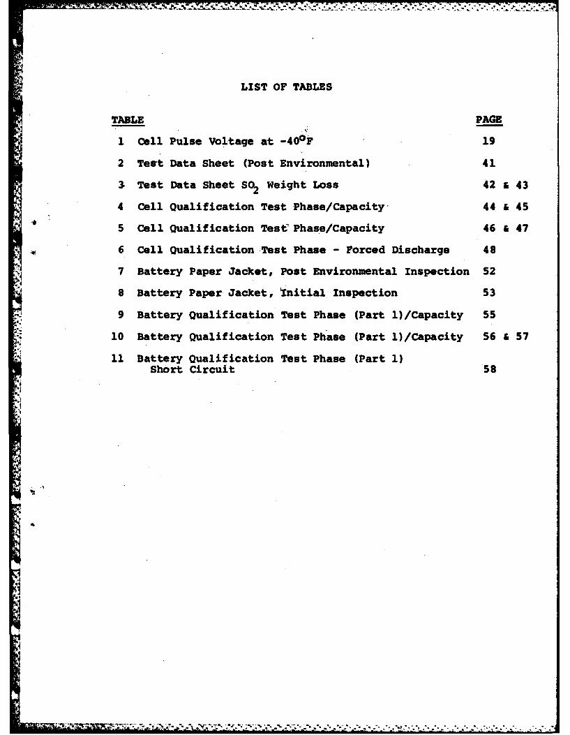
LIST OF TABLES
TABLE PAGE
1 Cell Pulse Voltage at -400 F 19
2 Test Data Sheet (Post Environmental) 41
3 Test Data Sheet S02 Weight Loss 42 a 43
4 Cell Qualification Test Phase/Capacity- 44 & 45
5 Cell Qualification Test Phase/Capacity 46 & 47
6 Cell Qualification Test Phase - Forced Discharge 48
7 Battery Paper Jacket, Post Environmental Inspection 52
8 Battery Paper Jacket, 'Initial Inspection 53
9 Battery Qualification Test Phase (Part 1)/Capacity 55
10 Battery Qualification Test Phase (Part 1)/Capacity 56 & 57
11 Battery Qualification Test Phase (Part 1)Short Circuit 58
IK
I
I.-: J-~ -Y~ ~ %*_ _**~
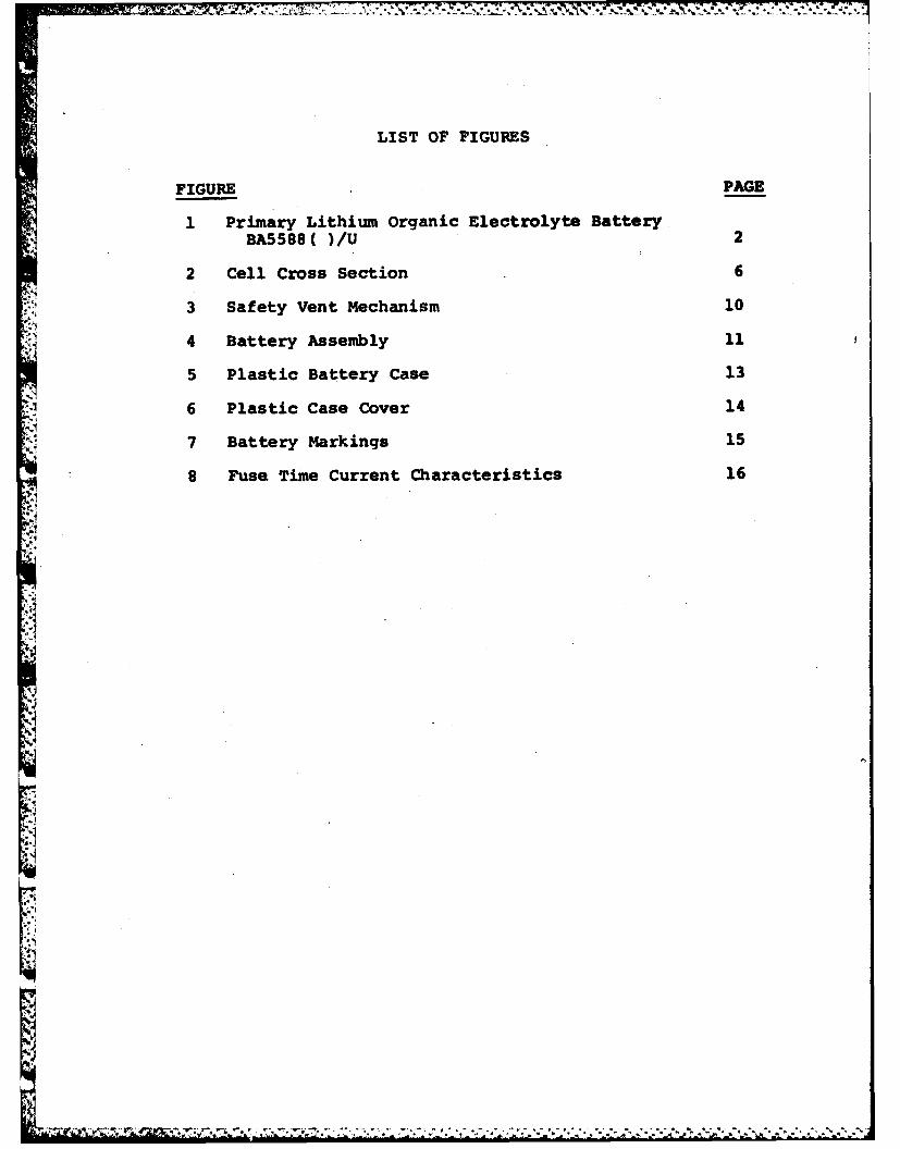
LIST OF FIGURES
FIGURE PAGE
1 Primary Lithium Organic Electrolyte BatteryBA5588( )/U 2
2 Cell Cross Section 6
3 Safety Vent Mechanism 10
4 Battery Assembly 11
5 Plastic Battery Case 13
16 Plastic Case Cover 14
7 Battery Markings 15
8 Fuse Time Current Characteristics 16
.. .....
1. OBJECTIVE
The subject Final Technical Report concerns the development,fabrication and testing of Battery BA-5588 ( )/U in ac-cordance with the performance and safety requirements asdefined in the Technical Guidelines for Primary LithiumOrganic Electrolyte Battery BA-5588 ( )/U dated 3 February 1978.Our primary concern has been the fabrication of the subjeetbatteries in conformance with these guidelines and thedemonstration of effective safety mechanisms and hermeticcell designs to insure non-hazardous battery operationunder all specified conditions of storage, use and operation.Such consideration included the safety vent design, cellelectrode configuration cell case design and configurationand electrical fuse protection within the battery.
2. REFERENCE DOCUMENTS
2.1 Contract No. DAAK20-79-C-0260, BA 5588 ( )/Udated 16 April 1979.
2.2 Technical Guidelines for Primary Lithium OrganicElectrolyte Battery BA 5588 ( )/U dated 3 February1978.
2.3 Environmental Test Reports Nos. ST-2220 andST-2398-OOC, Stanford Technology Corporationdated February 5, 1980 and May 29, lS30,respec-tively.
2.4 MIL-STD-810C Environmental Test Methods, 10 March1975.
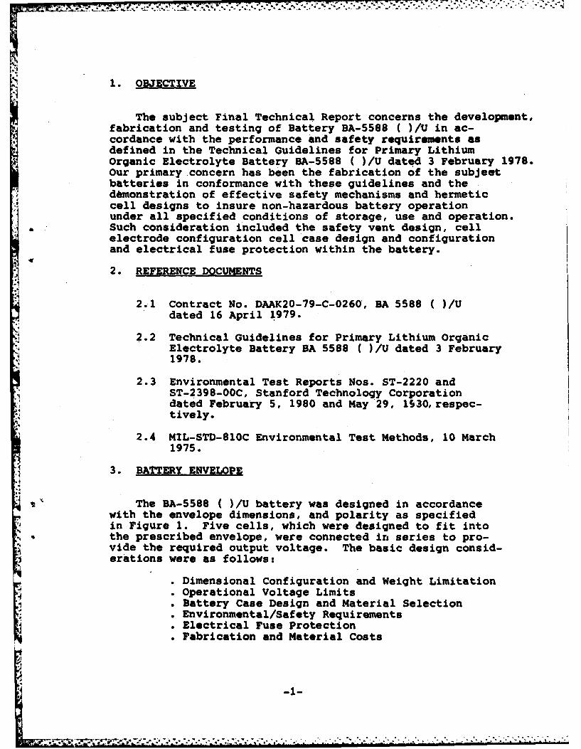
3. BATTERY ENVELOPE
The BA-5588 ( )/U battery was designed in accordancewith the envelope dimensions, and polarity as specifiedin Figure 1. Five cells, which were designed to fit intothe prescribed envelope, were connected in series to pro-vide the required output voltage. The basic design consid-erations were as follows:
• Dimensional Configuration and Weight Limitation. Operational Voltage Limits0 Battery Case Design and Material Selection0 Environmental/Safety Requirements. Electrical Fuse Protection0 Fabrication and Material Costs
'4 ' mr"; 'T + '7;'ii ""2'+' " : " " " .. . : " 'i' " - '" ' ': ' " '-1- -'
POKit - I -IIIM.
it IIto /IJUIA ISO)fouS
- -. . -* .t
5 SELL SATTEI!
$OCIET WIRINOSCKIE 1ATIC
* ME
MNE lEftt"EASLiL MITEIAL rust 1AISSI
L*CATI0 O 1tStcer
IfC Tit.
4 PLACIS
NJ. MOT43 LITOWtN mRANIO ELECTROLYTE BATTERY IA5584( )/U
-2-

The battery's physical, electrical-and performance require-ments as delineated in the Technical Guideline for PrimaryLithium Organic Electrolyte Battery BA-5588( )/U dated3 February 1978 are as follows;
3.1 Physical Characteristics
' Length (inch) 3.545 t 0.015
Width linch) 1.244 t 0.015
Height (inch) 3.485 t 0.015
Weight (lbs.) 0.75 maximum
,Volume (cubic Inches) 15.1
3.2 Electrical Characteristics
Operating Voltage Limits (volts) 12 to 15
Current (maximum) .34 amps pulsed
Capacity" +160 0F 2.87 amp-hrs." +130 0F 2.87 amp-hrs.* +700F 2.87 amp-hra.0 -400F .96 amp-hrs.
Energy (watt-hrs) 39.0
Energy Density (watt-hrs/lb) 52.1
Volumetric Energy Density 2.6(watt-hrs/in3)
3.3 Performance Requirements
The discharged performance requirements are asfollows:
3.3.1 Disohara. Profile
-3-
- -: ,- .,-,-, ,- . -. * *, . -- - . . ." -.. .* -, - . . . . .• - .- . * , - . -.- . - .. - -- -

The battery shall be pulse discharged through 40 ohmsfor one (1) minute followed by 207 ohms for nine (9)minutes repeated continuously to zero voltage.
The cell shall be pulse discharged through 8 ohms forone (1) minute followed by 41.4 ohms for nine (9) minutesrepeated continuously to zero voltage.
3.3.2 Voltage Delay
Upon start of discharge under any specified* test condition, closed circuit voltage below 12 volts (2.4
volts per cell) shall not exceed 0.1 second duration.
3.3.3 End Voltage
During the course of any battery dischargetest, the time at which the output voltage falls below 12volts is considered for determination of service life.
During the course of any cell discharge test,the time at which the output voltage falls below 2.4 voltsis considered for determination of service life.
3.3.4 Service Reauirements
The battery and cells are required to deliverthe following minimum service to the applicable end voltageunder the specified discharge profile for each of thefollowing conditions after exposure to any or all environ-ments or storage conditions:
(a) 30 hours service under discharge at +75 ±70F.
(b) 30 hours service under discharge at +130 4, 30 Ffollowing stabilization of thS battery for aminimum of 8 hours at 130 + 3uF.
(c 0hours srieunder discharge at +160 ± 30 Ffollowing stabilization of the battery for aminimum of 8 hours at 160 + 30F.
d)10 hours service under discharge at -40 ± 30Ffollowing stabilization of the battery for aminimum of 8 hours at -40 + 30F.
V 3.3.5 Environmental Tests
Cells and batteries shall deliver the specifiedminimum service requirements after exposure to the followingenvironmental tests:
C -4-
21.

yy;J
Temperature Shock - In accordance with MIL-STD-810C, Method 503.1 for five cycles (do not dischargeduring or immediately after test).
Shock - In accordance with MIL-STD-810C,Method 516.2 Procedure I, Curve 516.2-2 for ground equip-ment. (Do not discharge during or immediately after test.)
Vibration - In accordance with MIL-STD-810CMethod 514.2 Equipment Category (h), Procedure X and XI,Figure 514.2-7, Table 514.2-VII. (Do not operate duringor after test.)
Altitude - In accordance with MIL-STD-810B,Method 500.1 Procedure I. (omit Step 4; do not dischargeduring or immediately after test).
4. CELL DESIGN CONFIGURATION
4.1 Cell Selection
Several hermetic cell designs were evaluated underthis program in an effort to achieve all specified performanceand safety requirements. Various electrode configurationsand geometries were evaluated under the BA 5588 C )/Udischarge load profile. Parameters investigated includedthe following:
• Electrode Surface'Area. Lithium/SO2 Ratio
. Cathode Utilization Efficiency
. Cell Construction
Various cell configurations were evaluated and analyzedduring the Preliminary Design Cell Fabrication Phase andare discussed in paragraph 6 of this report.
The hermetically sealed lithium sulfur dioxidedescribed below, was utilized to fabricate the required
.4 BA 5588 ( )/U batteries.
4.2 Cell Design Considerations
The cell design, as illustrated in Figure 2, wasdefined in an effort to meet or exceed all performance,safety and environmental requirements. Basic design con-siderations included the following:
-5-

ro~so
El,-AC' A- % -6
rigure2
Cwx~-6-

7.77 77, --7.-777.7.77
" Discharge Capacity and Rate. Minimal Current Density Levels. Operational Voltage Limits. Voltage Delay Requirements" Dimensional Configuration and Weight Limitations" Environmental/Safety Requirements" Fabrication and Material Costs
4.2.1 Physical Characteristics
Diameter: 0.750 inchLength: 3.25 inchWeight: 44.5 gramsVolume: 23.5 cc
4.2.2 Electrode Configuration
The high rate cell design utilized in this battery re-quired maximum utilization of available internal cell volumein order to achieve the specified capacity levels and tomaximize start-up voltages, especially after thirty (30)
.* days storage at +160 0 F. The electrode design was based uponmaintaining a balanced stoichiometric proportion of the activecomponents, optimizing electrode utilization efficiency andminimal current density levels. The electrode characteristicswere as follows:
"3 Anode
Active Length (inch) 9.0Width (inch) 2.5Thickness (inch) .006Weight (grams) 1.18Theoretical Capacity (amp-hrs) 4.56
Cathode
Active Length (inch) 9.0Width (inch) 2.5Thickness (inch) .026Porosity (N) 85
Type Microporous PolypropyleneLength (inch) 24Width (inch) 2.75Thickness (inch) .001Porosity -45
-7-

S." Electrolyte
Weight (grams) 15.5
Theoretical Capacity (amp-hrs) 4.48
4q Electrical Characteristics
Electrode Surface Area (cm2) 290Current Density (ma/cm2)
8 ohms 1.2141.4 ohms 0.23
Li/SO2 Ratio 1.02
4.3 Cell Construction
The cell was constructed as follows to insure con-formance to-all dimensional and performance requirements:
The cell case consists of a nickel plated CRSalloy snslosure. A flanged nickel plated CRS fill portis wel ed to the can base to permit subsequent dispensingof electrolyte within the cell. The can base is configuredto permit installation of a welded contact button whichprotects the fill port closure and serves as the negativeelectrical connection. A mechanical safety vent mechanismis formed within the side wall of the cell case (see paragraph4.4).
N The top structure consists of a CRS shellshaped as shown so as to provide suitable surfacesfor peripheral welding.
The glass seal assembly consists of solid tantalumterminal which is hermetically fused to a CRS eyelet andsubsequently projection welded to the top shell structure Theterminal is coined at one end to provide a suitable contactsurface for electrical connection of the internal cathodetab.
anode The electrode core consists of a spirally woundanode and cathode assembly which are separated by aninsulative microporous polypropylene barrier; a configurationwhich maximizes electrode surface area. The assembled coreis inserted within the cell case and appropriate electricalconnections are.made prior to installation of the top structure.
?-8

• .1 The assembled cell is hermetically sealed along the-, case periphery using an arc welding process. Electrolyte
is subsequently dispensed within the cell at which timehermetic closure of the fill port is accomplished.
* 4.4 Safety Vent Mechanism
Since the lithium/SO2 electrochemical system utilizes*. a pressurized electrolyte, a pressure activated safety
vent mechanism was used to exhaust over-pressurized electrolyte* at a pre-determined temperature (equivalent to approximately
450 psi) to effect cell deactivation. The safety vent asshown in Figure 3, consists of a coined cross sectionlocated in the can wall and parallel to the center line;
:1 •a configuration which occupies minimal internal volume.The coined structure is rolled radially inward duringfabrication which accomplishes the following:
toonor Minimizes the bulging of the can outer diameter
to conform to the required envelope dimensions during allrequired thermal environments.
Provides a pivot configuration which minimizestensile loading of the coined surface during normal cellstorage and operating environments. The flexure joint isdesigned to invert at approximately 200 - 210OF at whichpoint, the coined section is subjected to direct tensileloading due to the electrolyte vapor pressure within thecell. Such action provides greater control and reproducibilityof the venting characterist.cs and permits a graduatedrelease of electrolyte upon venting.
Provides protection and isolation of the ventstructure during cell/battery assembly and handling toprevent accidental vent rupture or damage.
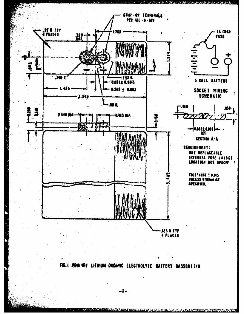
5. BATTERY DESIGN CONFIGURATION
The BA-5588 ( )/U battery design configuration, asshown in'Figure 4, consists of five (5) series connectedcells, each cell being 0.75 inches in diameter by 3.25inches long.
5.1 Battery Case
The battery case is fabricated from Borg Warner,
-9-

t.S... ~ - -, -. - -. -. - - - -
4
'I
1.4
~ ~ OF q/Ek4T M~E~4~4* 4 M~4 bAI\
.5
.9.
II
~ 4%ES~
.4
Figure 3
N
-10-
S -
BATTERY ASSEMBLY
C-T-
L K~ maws
- --- .%-
Fiqure0
*l 7L

BATTERY ASSEMBLY
4-_
C~/
CM+
Al?. MFigure -

• ~~~. ..-. '..'.-.'... .'..'.. ."... -. ...... -.. -... ".. ...-. .- "- . . -"
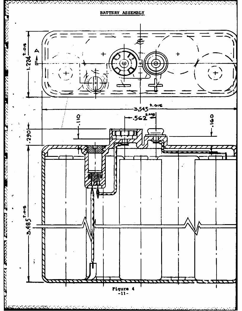
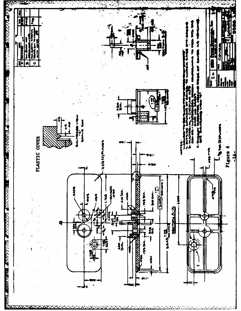
Cycolac KJW; and ABS flame retardant termoplastic materialwhich has an Underwriters Laboratories Flame Class Ratingof 94V - 0 at 0.058 "and 94-5V at 0.120". The case and casecover is shown in 5 and 6 respectively. Figure 7 is a drawingshowing the battery label and marking configuration.
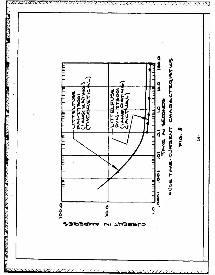
5.2 Electrical Fuse
The battery is electrically protected with areplaceable 1 ampere 5 second fuse located within thenegative leg of the cell stack assembly. The fuse assemblyconsists of a Littelfuse 281001 plug-in picofuse. Verifica-tion of the electrical fuse characteristics was performedto determine the time required for fuse activation atvarious current levels as it relates to the five (5)second requirement of the Technical Guidelines. Thesecharacteristics have been graphically represented inFigure 8, "Fuse Time Current Characteristics".
5.3 Connector
The electrical connectros utilized in the batterywere snap-on terminals per ML-B-18D, each having a spacingfrom the centerline of the battery of 0.281 + .0015 inches.The female snap connector was provided, as specified, witha peripheral cylindrical plastic shield which minimizesaccidental short circuiting of the battery.
5.4 Insulators
Mylar insulative cell jackets .002 inches thickwere installed over cell casings prior to fabricationof the cell stack assembly. As indicated in Figure 5, themolded battery case was provided with cell locating par-titions which also serve to act as insulating barriers forthe cell stack assembly.
5.5 Battery Venting
The battery cover is sealed to the case assemblyusing an ultrasonic weld technique. Each corner of thebattery is left unsealed to allow the gradual release of
overpressurized electrolyte in the event of venting of oneor more cells.
-12-

30
PI,
• . IA ... .j- . . i
8'do [(I
1'1. 1. rd
*. J! .1l;, "S_________ __Iil lll
II Iid Im
t'lot
0'+ + , •
A I r ral
pgii|... 1 - -, ,
_ _-_ 1 S_ . _ _ . . . . .
.4 .1
- ."+; + ,";' !*}':" ;:" ., -,; ' ,..-...,." ' ',.;..' . .". ". "-"+", - =. , , ,--.", .-. -. .- -
* ... ." . . '&'"*. *.* Q S . 3
'4' .• 4 -5 .
- SS* - ... .S
4 /o I
.. . ..
t~i owaA
AL.A
o -
' .
V - #a - -
1 ' r-;-!
*- -I,

7 I
I I I0Ama ui.
go,;M11
funl
15HJI volt
LthisOgol Eets rolyteI I
MT. ERNO, DY
FifYf.
ih
0 0 ,0 9
,4+. 4 -. - , - - -4 - . . 44 4 '. . .- . . . - .. " . + * . . . .. . . ..-
4.5
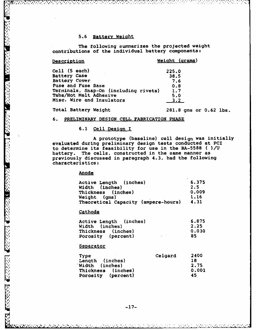
5.6 Battery Weight
The following summarizes the projected weightcontributions of the individual battery components:
Description Weight (crams)
Cell (5 each) 225.0Battery Case 38.5Battery Cover 7.6Fuse and Fuse Base 0.8Terminals, Snap-On (including rivets) 1.7Tabs/Hot Melt Adhesive 5.0Misc. Wire and Insulators 3.2
Total Battery Weight 281.8 gms or 0.62 lbs.
6. PRELIMINARY DESIGN CELL FABRICATION PHASE
6.1 Cell Design I
A prototype (baseline) cell design was initiallyevaluated during preliminary design tests conducted at PCIto determine its feasibility for use in the BA-5588 ( )/Ubattery. The cells, constructed in the same manner aspreviously discussed in paragraph 4.3, had the followingcharacteristics:
Anode
Active Length (inches) 6.375Width (inches) 2.5Thickness (inches) 0.009
Weight (gins) 1.16. Theoretical Capacity (ampere-hours) 4.31
Cathode
Active Length (inches) 6.875Width (inches) 2.25Thickness (inches) 0.030Porosity (percent) 85
Separator
Type Celgard 2400Lenqth (inches) 18Width (inches) 2.75Thickness (inches) 0.001Porosity (percent) 45
-17-

I IN
Weight (grams) 14.8Yolume (cc) 11.8
6.2 Base Line Tests
Cells were tested at +700F, +1600F and -400Fafter thermal stabilization for sixteen (16) hours. Eachcell was pulse discharged through eight ohms for one (1)minute followed by 41.4 ohms for nine (9) minutes repeatedcontinuously to zero voltage. The results were as follows:
Cell Discharge OCV Service Hours Service HoursS/N Temp ("F) (Volts) 1 2.4 Volts a 0 Volts
4 1 +70 2.97 38.8 41.62 +70 2.98 36.3 42.93 +70 2.98 37.6 40.84 +70 2.99 37.0 41.65 +70 2.98 35.1 40.76 +160 2.96 36.0 39.87 +160 2.96 33.9 42.08 +160 2.97 35.8 41.59 +160 2.96 35.8 40.010 +160 2.97 35.0 39.8
Cell Discharia OCV Start-up Service Hour6 Service HoursS/N Temp (OF) (Volts) Voltage 0 2.4 Volts . / its
__ lOOms11 -40 3.02 2.00 14.7 32.812 -40 3.02 2.07 16.2 35.113 -40 3.02 2.04 1!.3 34.014 -40 3.00 1.99 14.5 32.515 -40 3.01 2.10 15.5 36.0
These base-line results, while indicating that the capacityrequirements could be achieved at all specified dischargetemperatures, demonstrated this cells inability to meetthe minimum 2.4 volt 0.1 second start-up voltage requirement.As shown in Table 1 "Cell Pulse Voltage" discharge testsindicated that an average of seven (7) cycles were requiredto attain a minimum operating voltage of 2.4 volts at -40-F.
In order to determine the effect of electrode surface areaon cell pulse voltage, a PCI model 550-HR-S high rate "D"cell, with an effective electrode surface area of 390 cm
2
was subsequently tested at -40°F under the identicalBA-5588 cell discharge cycle.
-18-
"T '.'. -4 ", 4' . ,. " -4, . * - * - * - - . . . . -. . . .. . - -.-

Cell Pulse Voltage Voltage VoltageSIN # 100 ms @ 60 sec 0 41.4 ohms
_____ 8 ohms 8 ohms_______
11 1 2.00 2.16 2.4712 1 2.07 2.21 2.5013 1 2.04 2.19 2.49
11 2 2.22 2.25 2.5212 2 2.25 2.28 2 .5213 2 2.16 2.24 2.50
11 3 2.27 2.28 2.5312 3 2.29 2.30 2.5513 3 2.26 2.28 2.53
11 4 2.30 2.30 2.5612 4 2.31 2.33 2.5713 4 2.29 2.30 2.56
11 5 2.31 2.31 2.5612 5 2.34 2.34 2.5813 5 2.31 2.33 2.57
11 6 2.35 2.36 2.57V12 6 2.38 2.39 2.59
13 6 2,34 2.36 2.58
11 7 2.39 2.40 2.5812 7 2.41 2.41 2.6013 7 2.38 2.40 2.58
*11 20 2.44 2.45 2.6412 20 2.46 2.46 2.6513 20 2.44 2.44 2.65
11 40 2.45 2.45 2.6412 40 2.47 2.47 2.6613 40 2.46 2.46 2.65
Cell Pulse Voltage at -40OF
Table 1
-19-

The results, which have been tabulated below, showedthat the required start-up voltage specification could noteven be routinely obtained using the PCI 550-HR-S cell;a design with nearly twice the effective surface area ofthe BA-5588 cell.
* Cell # Pulse # Voltage Voltage Voltage@ 100 ms @ 60 sec @ 41.4 ohm
___8 ohms 8 ohms
1 1 2.16 2.40 2.632 1 2.10 2.33 2.623 1 2.04 2.34 2.64
1 2 2.41 2.45 2.642 2 2.32 2.34 2.633 2 2.37 2.39 2.64
1 3 2.45 2.46 2.642 3 2.38 2.40 2.643 3 2.40 2.41 2.64
Based on these results, initial efforts weredirected towards:
a.) determining the feasibility of utilizing asix (6) cell battery design. (This approachwas later abandoned due to the upper voltagelimits imposed by the equipment to be poweredby the subject battery.)
b.) investigating the effect of preconditioninS/shorting of the cell at 400F, by applicationof a short, high current pulse, prior tobattery use.
c.) determining cell start-up voltgge characteris-tics at temperatures above -40'F to quan-titatively define the thermal limitations ofthe present design.
6.3 Cell Redesign (Design II)
Specific recomnendations were made by ERADCOMin an effort to resolve voltgge delay problems encounteredduring cell discharge at -40 F. The cell was redesignedand a number of tasks were performed at the request ofERADCOM to supply additional performance information anddesign parameters.
-20-
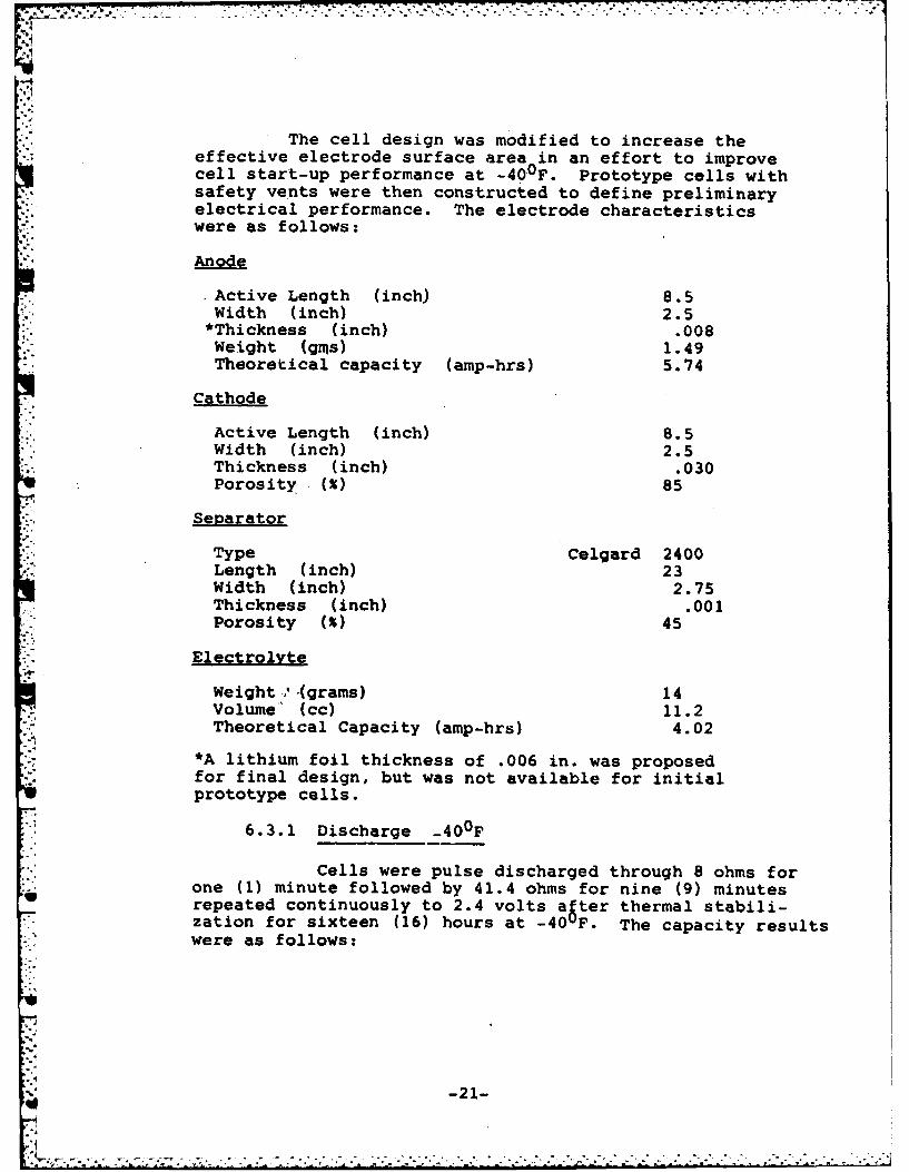
The cell design was modified to increase theeffective electrode surface area in an effort to improvecell start-up performance at -400F. Prototype cells withsafety vents were then constructed to define preliminaryelectrical performance. The electrode characteristicswere as follows:
Anode
.Active Length (inch) 8.5Width (inch) 2.5*Thickness (inch) .008weight (gms) 1.49
*Theoretical capacity (amp-hrs) 5.74
Cathode
Active Length (inch) 8.5Width (inch) 2.5Thickness (inch) .030Porosity M% 85
Separator
Type Celgard 2400Length (inch) 23Width (inch) 2.75Thickness (inch) .00 1Porosity M~ 45
Electrolyte
Weight .., -(grams) 14volume" (cc) 11.2Theoretical Capacity (amp-hrs) 4.02
*A lithium foil thickness of .006 in. was proposedfor final design, but was not available for initialprototype cells.
6.3.1 Discharge -40OF
Cells were pulse discharged through 8 ohms forone (1) minute followed by 41.4 ohms for nine (9) minutesli repeated continuously to 2.4 volts after thermal stabili-zation for sixteen (16) hours at -40uF. The capacity resultswere as follows:
-21-

.°
Start-upDischarge Voltage Service
Cell Temp OCV a 100 ms HoursS/N (oF) (volts) (volts) 32 vl
76 -40 3.03 2.14 13.077 -40 3.02 2.10 12.678 -40 3.01 2.07 14.179 -40 3.04 2.10 13.580 -40 3.02 2.07 12.9
These results again indicateg that the specificationcapacity requirements at -40 F were attainable. However,the start-up voltage requirement of 2.4 volts within 0.1seconds was not achieved, although the results were sig-nificantly improved from the previous baseline results.A summary of operational cell voltage during the abovedischarge is shown below for cells S/N 76 - 80:
Voltage Voltage VoltageClSN8100 ms S 60 sec S 41.4
_CellS/N Pulse# 8 ohms 8 ohms ohms
76 1 2.14 2.27 2.5477 1 2.10 2.25 2.5678 1 2.07 2.23 2.5579 1 2.10 2.28 2.5780 1 2.07 2.26 2.53
76 2 2.26 2.34 2.5777 2 2.25 2.31 2.5978 2 2.24 2.31 2.5879 2 2.29 2.34 2.5980 2 2.25 2.32 2.56
76 3 2.35 2.37 2.5977 3 2.32 2.34 2.6078 3 2.32 2.36 2.5979 3 2.35 2.38 2.5980 3 2.34 2.35 2.57
76 4 2.38 2.40 2.6077 4 2.35 2.37 2.6178 4 2.37 2.38 2.61
4 79 4 2.38 2.40 2.60o80 4 2.36 2.37 2.58
-2
'p.
-22-
_ ' . ..-. ., . . '.' - .,".. -. -. . - .. . . . . . .. . . . . . . . . .
Voltage Voltage Voltage@ 100 ms 660 sec @ 41.4
Cell SIN Pulse if8 ohms 8 ohms- ohms
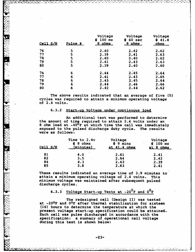
76 5 2.40 2.42 2.6277 5 2.39 2.41 2.6378 5 2.40 2.40 2.6279 5 2.41 2.43 2.6380 5 2.39 2.40 2.60
76 6 2.44 2.45 2.6477 6 2.41 2.43 2.6578 6 2.43 2.45 2.6479 6 2.44 2.46 2.6680 .6 2.42 2.44 2.62
The above results indicated that an average of five (5)cycles was required to attain a minimum operating voltageof 2.4 volts.
6.3.2 Start-up Voltaae under continuous load
An additional test was performed to determinethe amount of timS required to attain 2.4 volts under an8 ohm load at -40 "Fat which time the cell was immediatelyexposed to the pulsed discharge duty cycle. The resultswere as follows:
Time to 2.4v Voltage Voltage0 8 ohms @ 9 mins 6 100 ms
cell SIN (minutes) at 41.4 ohms at 8 ohms
81 4.0 2.61 2.4182 3.5 2.64 2.4284 4.3 2.63 2.3985 3.8 2.63 2.41
These results indicated an average time of 3.9 minutes toattain a minimum operating voltage of 2.4 volts. Thisminimum voltage was maintained after subsequent pulseddischarge cycles.
6.3.3' Voltage Start-up Tests at -200 F and 0
The redesigned cell (Design II) was testedat -20OF and 00F after thermal stabilization for sixteen(16) hours to determine the temperature at which thepresent voltage start-up specification could be attained.Each cell was pulse discharged in accordance with thespecification: a summary of operational cell voltageduring this test is shown below:
-23-

°Li
Teat Temperature: -20°F
Cell S/N Pulse # Voltage Voltage Voltage@ 100 us @ 60 see @ 41.4
"0 8 ohms 8 ohms ohms
86 1 2.22 2.32 2.6287 1 2.24 2.35 2.6488 1 2.19 2.31 2.6189 1 2.24 2.34 2.63
86 2 2.34 2.38 2.6387 2 2.37 2.42 2.65
- 88 2 2.32 2.37 2.6389 2 2.34 2.40 2.6490 2 2.37 2.42 2.65
86 3 2.39 2.43 2.6587 3 2.42 2.45 2.6688 3 2.37 2.40 2.6489 3 2.41 2.43 2.6690 3 2.43 2.46 2.67
Test Temperature: 0°F
Cell S/N Pulse # Voltage Voltage Voltage@ 100 s @ 60see @ 41.48 ohms 8 ohms ohm
91 1 2.40 2.51 2.6692 1 2.43 2.50 2.6593 1 2.41 2.50 2.6794 1 2.41 2.48 2.6795 1 2.42 2.52 2.67
The above results indicate that an average of 2.4 cycles wasrequired at -20 F to attain a minimum operating voltage of 2 4volts. The present start-up specification was attained at 0Fwith the "Design I1" type cell.
y The pulse start-up voltage delay was subsequentlyverified by c€ntinuougly applying an 8 ohm load at temperaturesof -40'F, -20OF and OF. The results below correlatequite closely to the data obtained under the pulsed dutycycle load.
Cell S/N Test Time-Temprature @ 2.4 volts
___F) (minutes)
96 -40 3.997 -40 3.5
-24-

Cell S/N Test TimeTemperature 02.4 volts
_______(OF) (minutes)
98 -20 1.7599 -20 2.0
100 0 100 ms101 0.00ms
6.3.4 Cathode Construction Investigation
As part of'this program, cathodes werefabricated using carbon, which was evenly distributed, onboth sides of the conductive grid to determine its effecton cell start-up voltage at -400F (PCI's standard elec-trodes have 95% of the active carbon/binder material on oneside of the expanded conductive substrate). Four (4) pro-totype cells were fabricated and pulse discharged through8 ohms for one (1) minute followed by 41.4 ohms for nine(9) minutes after thermal stabilization for sixteen (16)hours at -400F. The results, as summarized below, showno significant improvement in start-up performance ascompared to data previously obtained.
Cell S/N Pulse # Voltage Voltage Voltage*100 mns @ 60 sec 041.4
______8 ohms 8 ohms ohms
102 1 2.16 2.30 2.57103 1 2.16 2.28 2.57104 1 2.10 2.24 2.5310.5 1 2.09 2.25 2.54
102 2 2.30 2.36 2.59103 2 2.29 2.33 2.59104 2 2.25 2.30 2.58105 2 2.27 2.33 2.58
102 3 2.36 2.38 2.60103 3 2.34 2.36 2.61104 3 2.32 2.35 2.59105 3 2.34 2.37 2.59
102 4 2.39 2.41 2.61103 4 2.37 2.40 2.62104 4 2.36 2.38 2.61105 4 2.38 2.40 2.60
102 5 2.41 2.42 2.63103 5 2.41 2.42 2.63104 5 2.40 2.41 2.63105 5 2.40 2.43 2.60
-25-
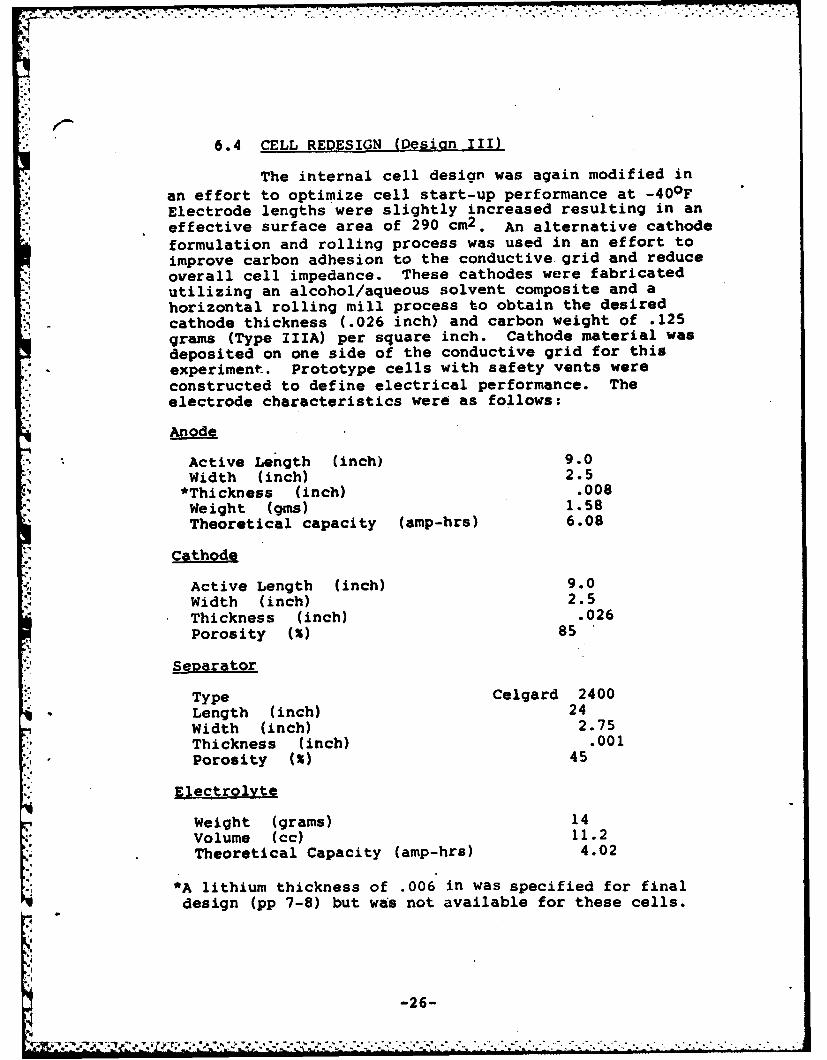
6.4 CELL REDESIGN (Resign III)
* The internal cell design was again modified inan effort to optimize cell start-u~p performance at -40OFElectrode lengths were slightly increased resulting in aneffective surface area of 290 cm2 . An alternative cathodeformulation and rolling process was used in an effort toimprove carbon adhesion to the conductive grid and reduceoverall cell impedance. These cathodes were fabricatedutilizing an alcohol/aqueous solvent composite and ahorizontal rolling mill process to obtain the desiredcathode thickness (.026 inch) and carbon weight of .125grams (Type IIIA) per square inch. Cathode material wasdeposited on one side of the conductive grid for thisexperiment. Prototype cells with safety vents were
* constructed to define electrical performance. Theelectrode characteristics were as follows:
Anodei
Active Length (inch) 9.0Width (inch) 2.5*Thickness (inch) .008Weight (gins) 1.58Theoretical capacity (amp-hrs) 6.08
Cathode
Active Length (inch) 9.0Width (inch) 2.5
Thickness (inch) .026Porosity M~ 85
Separator
Type Celgard 2400*Length (inch) 24
Width (inch) 2.75Thickness (inch) .001Porosity M~ 45
Electrolyte
Weight (grams) 14Vvolume (cc) 11.2
Theoretical Capacity (amp-hrs) 4.02
*A lithium thickness of .006 in was specified for finaldesign (pp 7-8) but was not available for these cells.
-26-

6.4.1 Start-up Tests -40OF; Cathode 0.125 ams C/in2 (III A)
These prototype cells were subsequently testedat -400F after thermal stabilization for sixteen (16)hours. Each cell was pulse discharged through 8 ohmsfor one (1) minute followed by 41.4 ohms for nine (9)minutes repeated continuously to 2.4 volts. The results,as summarized below, show a slight improvement in start-up performance as compared to data previously obtained onType II cells.
Desion III A Cells
Voltage Voltage Voltage! 100 ms S 60 sec @ 41.4 ohms
CeI S/N Pulse # 8 ohms 8 ohms-
106 1 2.19 2.32 2.57107 1 2.17 2.28 2.57108 1 2.16 2.28 2.56109 1 2.21 2.33 2.58110 1 2.19 2.30 2.57
106 2 2.32 2.35 2.60107 2 2.30 2.33 2.59108 2 2.30 2.32 2.58109 2 2.34 2.35 2.60110 2 2.31 2.34 2.59
106 3 2.36 2.39 2.62107 3 2.34 2.37 2.61108 3 2.33 2.36 2.60109 3 2.35 2.38 2.61110 3 2.36 2.38 2.60
106 4 2.40 2.42 2.63107 4 2.39 2.41 2.62108 4 2.38 2.40 2.61109 4 2.39 2.41 2.62110 4 2.40 2.42 2.62
6.4.2 Cell Start-u_ Voltage After Partial Predischaraina
Additional Type IIIA cells were predischarged(preconditioned) by applying a 1.5 ohm resistance for ten(10) minutes (approximately 0.3 AH) to reduce the internalimpedance of t~e cell. Five cells were subsequentl6stored at +160 F for two (2) days and tested at -40Fafter thermal stabilization for sixteen (16) hours. Eachcell was pulse discharged through 8 ohms for one (1)minute followed by 41.4 ohms.for nine (9) minutes repeatedcontinuously to 2.4 volts. The results, as summarized below,
.. I
-27-
OIv

show a significant improvement in start-up performance.The average time to attain a minimum of 2.4 volts was 50seconds.
Voltage Voltage Voltage" 100 ms 6 60 sec. 6 41.4 ohms
Cell SIN Pulse # 8 ohms _8 ohms
116 1 2.23 2.42 2.63117 1 2.25 2.40 2.62118 1 2.29 2.44 2.64119 1 2.21 2.41 2.62120 1 2.21 2.41 2.62
6.4.3 Start-Up Voltace Tests; Cathode 0.160 ams C/in2 (III B)
Additional "Design III" cells were fabricatedusing cathodes fabricated with an alcohol/aqueous solventcomposite and a horizontal rolling mill process to obtainthe desired cathode thickness (.026 inch) and an increasedweight to .160 grams (Type IIIB) of carbon per square inch.Cathode material was deposited on both sides of the con-ductive grid to increaje the effective electrode surfacearea.
These prototype cells were subsequently testedas before. The results, as summarized below, show no
2 improvement in start-up performance as compared to dataobtained with Type III A cathodes having .125 gms carbonper square inch.
Type IIIB CellsVoltage Voltage VoltageS 100 ms S 60 sec. 6 41.4 ohms
Cell SIN Ple8 ohms 8 ohms _.__
111 1 2.16 2.30 2.57112 1 2.20 2.32 2.57113 1 2.16 2.26 2.55
* 114 1 2.19 2.28 2.56115 1 2.22 2.33 2.58
111 2 2.30 2.34 2.59112 2 2.33 2.35 2.58113 2 2.27 2.30 2.56114 2 2.30 2.33 2.57115 2 2.34 2.36 2.59
111 3 2.34 2.37 2.60112 3 2.35 2.38 2.60113 3 2.31 2.35 2.58114 3 2.34 2.37 2.59115 3 2.37 2.40 2.60
-28-

Voltage Voltage Voltage@ 100 ms @ 60 sec @ 41.4
Cell SIN Pulse # 8 ohms 8 ohms ohms
il 4 2.38 2.40 2.61112 4 2.38 2.40 2.61113 4 2.36 2.39 2.59114 4 2.37 2.40 2.60115 4 2.41 2.43 2.62
6.4.4 Start-Up Voltaae Tests Multiple CathodeGrids (TVpe IIIC)
An experiment was subsequently conducted to deter-mine the effect of multiple conductive grids within thecathode. Prototype cells" using the standard cathode formula-tion and two aluminum current collection grids were fabrica-ted using the electrode design as summarized in paragraph 6.4.
These cells were subsequently tested at -400Fafter thermal stabilization for sixteen (16) hours. Eachcell was pulse discharged through 8 ohms for one (1)minute followed by. 41.4 ohms for nine (9) minutes repeatedcontinuously to 2.4 volts. The results, as summarized below,show somewhat poorer start-up performance as compared to datareported in paragraphs 6.4.1. Such results are attributed tothe reduced effective surface area of the cathode due to themasking effect of the two conductive grids which wereutilized.
Cell S/N Pulse # Voltage Voltage Voltage§ 100 ms S 60 sec. 0 41.4 ohms
8 ohms 8 ohms
121 1 1.80 2.06 2.47122 1 1.89 2.08 2.49123 1 1.82 1.94 2.48124 1 1.93 1.99 2.50125 1 1.96 2.09 2.50
121 2 2.14 2.15 2.52122 2 2.18 2.20 2.59123 2 2.16 2.17 2.53124 2 2.19 2.23 2.58125 2 2.20 2.24 2.58
121 3 2.20 2.20 2.55122 3 2.25 2.26 2.57123 3 2.23 2.23 2.55124 3 2.26 2.28 2.58125 3 2.27 2.30 2.59
-29-
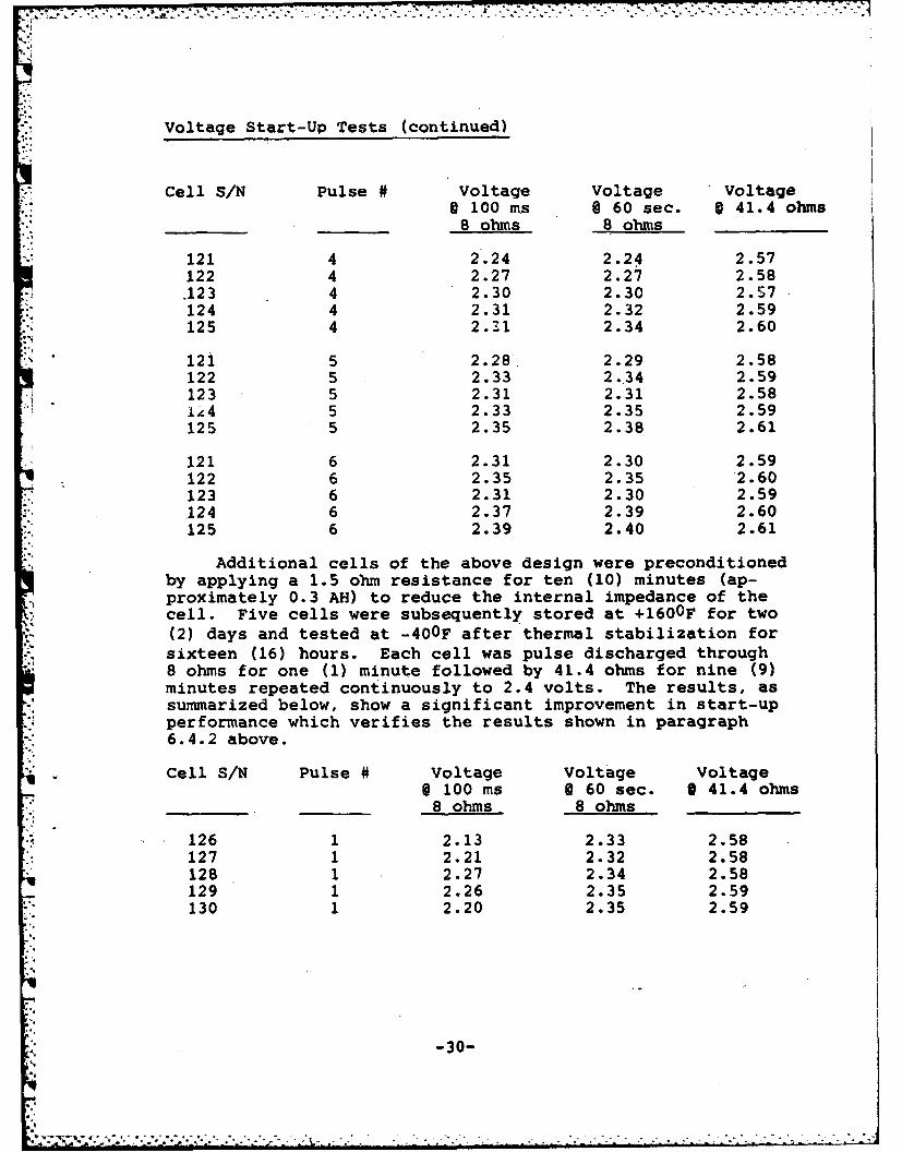
Voltage Start-Up Tests (continued).
Cell SIN Pulse # Voltage Voltage Voltage@ 100 ms §60 sec. §41.4 ohms
* _______ _______8 ohms 8 ohms_ _ _ _ _ _
121 4 2.24 2.24 2.57122 4 2.27 2.27 2.58.123 4 2.30 2.30 2.57124 4 2.31 2.32 2.59125 4 2.31 2.34 2.60
121 5 2.28. 2.29 2.58122 5 2.33 2.'34 2.59123 5 2.31 2.31 2.58
i45 2.33 2.35 2.59125 5 2.35 2.38 2.61
121 6 2.31 2.30 2.59122 6 2.35 2.35 '2.60123 6 2.31 2.30 2.59124 6 2.37 2.39 2.60125 6 2.39 2.40 2.61
Additional cells of the above design were preconditionedby applying a 1.5 ohm resistance for ten (10) minutes (ap-proximately 0.3 AH) to reduce the internal impedance of thecell. Five cells were subsequently stored at +1600F for two(2) days and tested at -40OF after thermal stabilization forsixteen (16) hours. Each cell was pulse discharged through8 ohms for one (1) minute followed by 41.4 ohms for nine (9)minutes repeated continuously to 2.4 volts. The results, assummarized below, show a significant improvement in start-upperformance which verifies the results shown in paragraph6.4.2 above.
Cell SIN Pulse # Voltage Voltage Voltage@ 100 ms 060 sec. 041.4 ohms
_____ __ __ ____8 ohms- 8 ohms ______
126 1 2.13 2.33 2.58127 1 2.21 2.32 2.58128 1 2.27 2.34 2.58129 1 2.26 2.35 2.59130 1 2.20 2.35 2.59
-30-
-I7
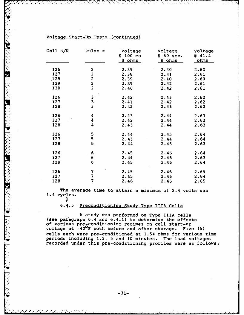
Voltage Start-Up Tests (continued)
Cell SIN Pulse # Voltage Voltage Voltage@ 100 ms @ 60 sec. @ 41.4
_____ ____ 8 ohms 8 ohms ohms
*126 2 2.39 2.40 2.60127 2 2.38 2.41 2.61.128 2 2.39 2.40 2.60129 2 2.39 2.42 2.61130 2 2.40 2.42 2.61
126 3 2.42 2.43 2.62127 3 2.41 2.42 2.62128 3 2.42 2.43 2.62
126 4 2.43 2.44 2.63127 4 2.42 2.44 2.62128 4 2.43 2.44 2.63
126 5 2.44 2.45 2.64127 5 2.43 2.44 2.64128 5 2.44 2.45 2.63
126 6 2.45 2.46 2.64127 6 2.44 2.45 2.63128 6 2.45 2.46 2.64
126 7 2.45 2.46 2.65127 7 2.45 2.46 2.64128 7 2.46 2.46 2.65
The average time to attain a minimum of 2.4 volts was1.4 cycles.
6.4.5 -Preconditioning Study Type IIIA Cells
A study was performed on Type IIIA cells(see paragraph 6.4 and 6.4.1) to determine the effectsof various pre-conditioning regimes on cell start-upvoltage at -40OF both before and after storage. Five (5)cells each were pre-conditioned at 1.54 ohms for various timeperiods including 1,2, 5 and 10 minutes. The load voltagesrecorded under this pre-conditioning profiles were as follows:
-31-

Cell S/N OCV Start-up TimeVoltage Final Duration
-------------- (5 seconds) Voltacie (mins)
129 2.97 2.32 2.68 10130 2.96 2.40. 2.69 10131 2.97 2.35 2.70 10132 2.96 2.38 2.70 10133 2.96 2.41 2.69 10
134 2.96 2.34 2.66 5- 135 2.96 2.42 2.67 5
136 2.96 2.34 2.66 5137 2.97 2.36 2.66 5138 2.95 2.41 2.65 5
139 2.96 2.32 2.65 2
140 2.95 2.33 2.62 2141 2.96 2.30 2.62 2
- 142 2.96 2.28 2.64 2143 2.96 2.48 2.63 2
144 2.95 2.36 2.58 1145 2.96 2.31 2.55 1146 2.95 2.33 2.59 1
* 147 2.90 2.59 2.66 1148 2.97 2.29 2.60 1
• Inadvertantly shorted during test.
Representative samples of the above cells were pre-conditioned in an identical manner, stored for two (2)days at +160OF and tested at -40OF after thermal stabiliza-tion for sixteen (16) hours. Each cell was pulse dischargedthrough 8 ohms for one (1) minute followed by 41.4 ohms fornine (9) minutes repeated continuously to 2.4 volts.The results, as summarized below, show equivalent start-upperformance for these cells independent of the pre-conditioningdischarge profile.
Cell Pre-condition Time"/NL Profile @ 1.54 ohms
149,150 10 minutes151,152 5 minutes153,154 2 minutes155,156 1 minute
-32-
......ar -........ . ... . .. ...... .......... *.,. ~ .,~* .
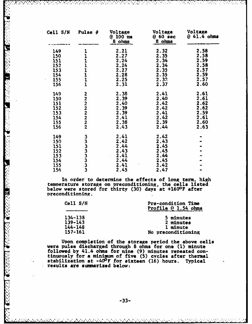
Cell SIN Pulse # Voltage Voltage Voltage@ 100ms @60 sec @41.4 ohms
8 ohms 8 ohms ______
149 1 2.21 2.32 2.58150 1 2.27 2.35 2.58151 1 2.24 2.34 2.59152 1 2.24 2.34 2.58153 1 2.27 2.35 2.57154 1 2.28 2.35 2.59155 1 2.25 2.32' 2.57156 1 2.31 2.37 2.60
149 2 2.38 2.41 2.61150 2 2.39 2.40 2.61151 2 2.40 2.42 2.62152 2 2.39 2.42 2.62153 2 2.39 2.41 2.59154 2 2.41 2.42 2.61155 2 2.38 2.39 2.60156 2 2.43 2.44 2.63
149 3 2.41 2.421.50 3 2.42 2.43151 3 2.44 2.45152 3 2.43 2.45153 3 2.41 2.44154 3 2.44 2.45155 3 2.41 2.42156 3 2.45 2.47
In order to determine the effects of long term, hightemperature storage on preconditioning, the cells listedbelow were stored for thirty (30) days at +1600 F afterpreconditioning.
Cell S/N Pre- condition TimeProfile Q 1.54 ohms
134-138 5 minutes139-143 2 minutes144-148 1 minute157-161 No preconditioning
Upon completion of the storage period the above cellswere pulse discharged through 8 ohms for one (1) minutefollowed by 41.4 ohms for nine (9) minutes repeated con-tinuously for a minimum of five (5) cycles after thermalstabilization at -40OF for sixteen (16) hours. Typicalresults are swuamrized below:
-33-

-7 . .
Cell Pulse Voltage Voltage VoltageSIN #@ 100 mis @ 60 sec @ 41.4 ohms
_____8 ohms 8 ohms ______
134 1 .50 .69 2.38135 1 .94 1.70 2.48136 1 .61 .87 2.36141 1 .1.21 1.45 2.43142 1 1.43 1.83 2.48143 1 1.56 1.94 2.5014 4 1 1.23 1.80 2.47145 1 1.42 1.79 2.48146 1 1.83 1.95 2.48157 1 1.85 2.07 2.54158 1 1.78 2.04 2.52159 1 1.64 1.93 2.47
134 2 2.06 2.19 2.49135 2 2.20 2.30 2.54136 2 2.02 2.19 2.47141 2 2.08 2.09 2.49142 -2 2.22 2.23 2.54143 2 2.23 2.26 2.56144 2 2.16 2.18 2.51145 2 2.16 2.82.52146 2 2.15 2.14 2'.50157 2 2.21 2.22 2.57158 2 2.22 2.23 2.56159 2 2.20 2.27 2.53
134 3 2.21 2.14 2.53.135 3 2.29 2.27 2.57136 3 2.15 2.13 2.51141 3 2.18 2.15 2.52142 3 2.30 2.30 2.57143 3 2.31 2.32 2.58144 3 2.24 2.23 2.56145 3 2.24 2.23 2.56146 3 2.20 2.16 2.52157 3 .2.27 2.27 2.59158 3 2.28 2.29 2.59159 3 2.28 2.28 2.56
-34-

cell Pulse Voltage Voltage VoltageSIN # l100ms @ 60sec @ 41.4 ohms
8 ohms 8 ohms@______
134 4 2.27 2.18 2.54135 4 2.34 2.32 2.58136 4 2.22 2.18 2.53141 4 2.22 2.19 2.54142 4 2.34 2.34 2.59143 4 2.35 2.36 2.60144 4 2.28 2.27 2.58145 4 2.28 2.28 2.58146 4 2.23 2.18 2.54157 4 2.31 2.31 2.60158 4 .2.32 2.33 2.60159 4 2.31 2.32 2.59
134 5 2.30 2.22 2.56135 5 2.36 2.34 2.59136 5 2.25 2.20 2.45141 5 2.72.22 2.59142 5 2.38 2.37 2.59143 5 2.38 2.38 2.61144 5 2.32 2.30 2.59145 5 2.33 2.31 2.59146 5 2.28 2.20 2.55157 5 2.31 2.36 2.6115,8 5 2.35 2.35 2.61159 5 2.34 2.35 2.60
The results indicated that the preconditioning profilesevaluated did not provitde any beneficial effects on start-upvoltage after thirty days storage at +160 0F.
7. CELL FABRICATION AND TEST PHASE
The specified test program was performed to providethe following:
-Demonstration of cell hermeticity and integrityafter prolonged exposure to elevatedtemperatures and environmental tests.
-Evaluation of cell performance under thespecified resistive load discharge profileat various temperatures after thirty (30) daysstorage at +-1600F'.
-Demonstration of cell safety under specifiedabusive test environments.
-35-
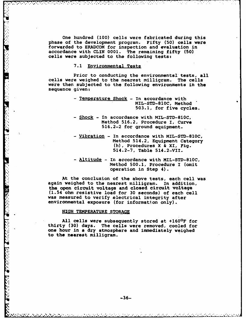
One hundred (100) cells were fabricated during thisphase of the development program. Fifty (50) cells wereforwarded to ERADCOM for inspection and evaluation inaccordance with CLIN 0001. The remaining fifty (50)
'1 cells were subjected to the following tests:
7.1 Environmental Tests
Prior to conducting the environmental tests, allcells were weighed to the nearest milligram. The cellswere then subjected to the following environments in thesequence given:
- Temperature Shock - In accordance withMIL-STD-810C, Method503.1, for five cycles.
- Shock - In accordance with MIL-STD-810C,Method 516.2, Procedure I, Curve516.2-2 for ground equipment.
- Vibration - In accordance with MIL-STD-810C,Method 514.2, Equipment Category(h), Procedures X & XI, Fig.514.2-7, Table 514.2-VII.
- Altitude - In accordance with MIL-STD-810C,Method 500.1, Procedure I (omitoperation in Step 4).
At the conclusion of the above tests, each cell wasagain weighed to the nearest milligram. In addition,the open circuit voltage and closed circuit voltage(1.54 ohm resistive load for 30 seconds) of each cellwas measured to verify electrical integrity afterenvironmental exposure (for information only).
HIGH TEMPERATURE STORAGE
All cells were subsequently stored at +160°F forthirty (30) days. The cells were removed, cooled forone hour in a dry atmosphere and immediately weighedto the nearest milligram.
-36-
-. ...-.- 7-- k-.. 7

7.2 Discharge Tests
Room Temperature Tests - After undergoing the en-vironmental and high temperature storage tests, ten (10)cells were selected at random and discharged under thespecified load profile at 75OF + 70F. The cells werestabilized at that temperature 'or at least one hourprior to discharge. The cell discharge was continuouslymonitored for temperature and voltage to zero volts.The cells service life requirement is thirty (30) hoursminimum.
Elevated Temperature Tests - Ten cells were randomlyselected from the remaining cells, stored at +130OF fora minimum of eight (8) hours and discharged under thespecified load profile at 130OF + 300F. The cell dischargewas monitored for temperature and voltage to zero volts.The cells service life requirement is thirty (30) hoursminimum.
High Temperature Tests - Ten cells were randomlyselected from the remaining cells, stored at 160OF + 30Ffor a minimum of eight (8) hours and discharged underthe specified load profile at 160OF + 30F. The celldischarge was monitored for temperature and voltage tozero volts. The cells service life requirement is thirty(30) hours minimum.
Low Temperature- Ten cells were randomly selectedfrom We remaining cells, stored at -40OF for a minimumof eight (8) hours and discharged under the specifiedload profile at -400F. The cell discharge was contin-uously monitored to zero volts. The cells service liferequirement is ten (10) hours minimum.
Forced Discharge - The remaining ten (10) cellswere force dicarged by placing each cell in serieswith a power supply and driving it at 0.5 amperes
without interruption for sixteen (16) hours or untilventing occurs. Time to venting, cell temperature,voltage and current were recorded. The tests were con-ducted under room temperature conditions.
-37-
P 'L, .- . . . .... .. .. o +... .. . .

7.3 TEST RESULTS AND OBSERVATIONS
7.3.1 Environmental Tests
The results and observations of the specifiedenvironmental tests (temperature shock, shock, vibration)are described in Appendix A, Stanford Technology Corpora-tion, Test Report ST-2220 dated 5 February 1980. Allcells successfully passed the above environmental testswith the exception of SIN 69 which exhibited evidenceof electrolyte leakage adjacent to the fill port closureimmediately following exposure to Temperature Shock.This leakage was subsequently verified by a resultingloss of cell weight.
Subsequent failure analysis showed that the observedelectrolyte leakage was due to a cracked weld withinthe fill port closure; a'condition most likely due tostresses developed during the thermal shock environment.The following corrective action was implemented toscreen this condition-on subsequent cells:
-Completed cells will be subjected to three(3) days storage at +1600F after electrolytefill. A visual examination for electrolyteleakage will be conducted after each dayof storage.
-Inspection surveillance of the fill portclosure operation will be increased toverify the quality of the welded jointand the use of proper weld parameters.
All cells (with the exception of S/N 69) weresubjected to the Altitude Test as specified. Theresults are summarized in Appendix B. No electrolyteleakage or other adverse effects were observed duringor after environmental exposure.
* 7.3.2 Electrical Check
The open circuit voltage (OCV) and closedcircuit voltage (CCV) at 1.54 ohms, 30 seconds, wasmeasured to determine the electrical condition of thefifty (50) cells after environmental exposure. The resultsare summarized in Table 2. No evidence of cell failurewas observed.
-38-

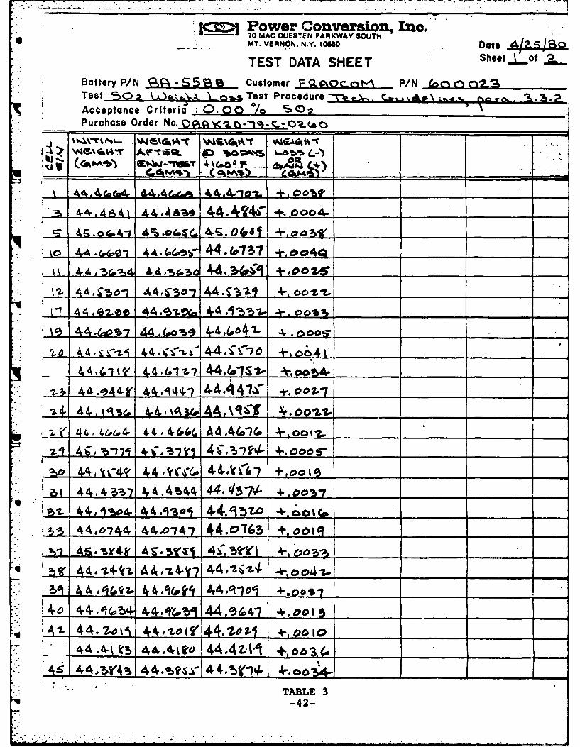
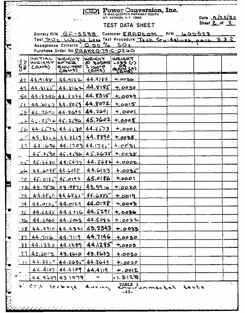
7.3.3 Cell Hermeticity
Cell weight values to the nearest milligramtaken during various phases are presented in TableThe results show that the maximum weight loss did notexceed 0.00 percent of the sulfur dioxide content of thecell after enviromental exposure and storage at +160oFfor thirty (30) days (with the exception of S/N 69 aspreviously discussed). Observed cell weight variationsare within the sensitivity of the analytical balance.All cells showed a slight weight gain; a conditionattributed to moisture absorption of the insulativemylar jacket and epoxy encapsulant within the topshell assembly. No visual evidence of electrolyteleakage was observed on any of the cells.
7.3.4 Caacity Tests
Thirty nine (39) cells were randomly selected* from the cells that had undergone environmental exposure
and +160OF storage for thirty (30) days. Ten (10) cellswere discharged after stabilization for eight (8) hoursat +1600F, +130OF and -40OF. Nine (9) cells were dis-charged at +700F. Each cell was pulse discharged through8 ohms for one (1) minute followed by 41.4 ohms for nine(9) minutes repeated continuously to zero volts. Celloutput voltage and temperature was continuously monitoredas soecified. The capacity discharge results are shownin Table 4. No cell venting was observed during dis-charge to zero volts. The results show that the cellssuccessfully complied with all specified minimum servicelife requirements.
The minimum start-up voltage requirement of 2.4volts within 0.1 seconds was not achieved during dischargeat -40OF. The results indicate that an average of 6.6cycles was required to attain a minimum operating voltageof 2.4 volts after cell storage at +160°F for thirty(30) days. A sumnary of operational cell voltage duringthe first eight (8) cycles of the -40°F discharge is shownin Table 5.
7.3.5 Forced Discharre
The remaining ten (10) cells were force dis-charged at 0.5 amperes without interruntion for sixteen(16) hours or until venting occurred. Time to venting,cell temperatures, output voltage and current was con-tinuously monitored as specified. The results, as summarizedin Table 6, showed that the cells complied with all safetyrequirements of the Technical Guidelines. No explosiveconditions or other adverse effects were observed.
-39-

7.4 CONCLUSIONS:
Electrical Performance
Cell capacity exceeded all minimum servicerequirements under the discharge load temperatures afterstorage at +1600F for thirty (30) days. An averageof 6.6 load cycles (transmit/receive) was required toattain a minimum cell operational voltage of 2'.4 voltsunder the 8 ohm resistive load (transmit mode) at -400F.No electrolyte leakage or other adverse conditions wereobserved after environmental exposure and storage forthirty (30) days at +160 0F.
Safety Performance
All cells performed satisfactorily under thespecified abusive test environments in accordance with therequirements of the Technical Guidelines.
-40-

Power Conver 1on, Inc.70 MAC QUESTEN PARKWAY SOUTHMT. VERNON, N.Y. 10550 Date 2-76-60
TEST DATA SHEET Sheet..of /
Battery P/N ,5-5 6:/0 Customer F..L .."# P/N b O o8Test A.--A,- C CW Test Procedure oc.-,. , r.c-. (P r .Acceptance Criteria 0QAN *g o t.I' LI'Purchase Order No. t ____. _--_-_._-O_
II .... tFiJ
-1- - . I_ I iwV
.... 2 .. z-64- ,_ _ 4_ 7 1_2,97 2,_ -__
" S .'i-z, s4- 1 2.97 -2. S0
s4-I - n I P.%.1 7 2 .9 4 •Z .
")S z~ 35 58 -207 2.17___( Z I..9<-::~~~~0- Z',& ..'' ".:9 ",7 ",-z-4. .. 59 2,7 2.2- __
,*¢ z.4o 7_ _"_._____%
-7__ 7.9 __0-) 7_ _I
-3 .1 3& 2,4 73 - 29 4
7.3 7 232- ,74 1 zI2 -
0291 2 S 29 . 7
-Z_ 0_, z ,-- , _30 ,2.31 ____
-i; ' .7 7 __"__._ _ _ __,77_ 7 I_ -.'_ _ _
z-35 be '2.9-7 "2 ,s_ _
7. .,C 1".7 7,.3 _ _ _ 76 '2,97 ".z, __ _ _ _' 87 I
S4 j____ 7 2",__, 89 2,97 "z, 36-
.2 '" 72.!34 _ I2 1__ _7 '.07 2,40_.___ -__._,__ ___ _. 2.,91 -_ .,___ __ _
TABLE 2*-41-
1 , n Power Conversion, Inc.70 MAC OUESTEN PARKWAY SOUTHMT. VERNON. N.Y. 10560 Date
TEST DATA SHEET Sheot Vf Battery P/N !6-B5A Customer o_ QcgoM P/N in"(o2_'ATest So X _ _, Test Proceduret-e _. .\ ,.. .Acceptance Criteria 0 .00 /o S, -Purchase Order No. O: --. O _
:.i t 4.4,,,4 ,. 44,.4-,so 44." oTW +,oo4-4031. +. I .000.
2w 4 . ;A o- AAA~ _ _So _ _ -ll
-LL 44010 4A 931% 44.c,1371 +,oos_ _l
Ji 4 4 44,~.~ -. 0
42. 4.4€1t 6 -&,7144 .4 +,D2.1-
44 -,4~ 44 .- ~A4444- 4_____
4 -6. A3 4.4,4 4.c9oi
4 ,4e&4- 4 4,i~ (o o 4 4(oi w_ __ _ o_ __ _ ___ _
- .4!; e2± ________ 4_ __ _ C,___-_I__-_N_+00 S
2) 1 4 4 4,:a-5 - 4,4.4 U4,44,43-7- +,_., .
.L 44,1w4- 4, .,Isol4 - 4-4.953o +,oolc. I_,
. 1 44,0744 44O0'747 44.0763 +.0015j
U ~j 44.- 11 Az 4,l.4442-I4iz oo 2. 7- __ ___ ___
44 o% 1 - - A -.
4 44 MCA__ ___ A 4 4. ______ 4 __-__,_
TABLE 3-42-
.............. .... ... .... . , .
= | 2 Power Conversion, Inc.70 MAC QUESTEN PARKWAY SOUTH
. MT. VERNON. N.Y. 10550 . Date 4I.I S 0
TEST DATA SHEET Sheet.f._o
Battery P/N (%,-S% Customer E OcV' ..ot* P/N c~l2.
Test '!:- 0 L , - . L - Test Procedure - .
Acceptance Criteria . m. 00 sc S0Purchase Order No..O.r Zl .O-"o -C.- 02. _
A-i 44 i4v 4 , 'i L-1 44 " .-qt _ _"
_ 00_6G
/A, C,_i_ 4_,oiI_ _4._ lr_ , ,oo a
-5a 4 4 -if4 6- 4. ,"1 44. T5 .%6 --,0'
S ___1 44 .- go -) k444. Iro 2-_ _ _ __ _ _ _ _
.-..i..'a- e~1, - 144 -2 61j1., + .oool/_-,_ _ _ '_ ''1
~±I4JZ i~~Z 46V274041 .0pt-.oX
44, 4-,ool __
4: - 4 t 4144- 11 ,,' _-44,1 -7+, _ _" I
4 .Z .0 4; - l 4i 7 4 4r e
____.-" 4 I , 4',4 t -oooz.4, Ir- 4 4,, i4. ,o o. _ _ _ _ _
to 44,toW 44,(,o it__ ______7, __ _ 0_ __ to___
T 4. - ,.": 44, . ,€z.4, V i/r +.P0o% C4' 4,- 6 Z, 4 0(1 44- 2f
-'*.4 7_L4f,4O( 4 ,O Io 14(,, g' +,oo44 _I
24 4, tV-7(O 4 4~ i _Z- 45 ______ ______
.. 4" ,TABLE _ _ 45_306*Al46,4 44-119 ;-44.-7 A (a +,obo i
* j44A2/cz. 44 Al"t 4 4A2~' KI tiv
A.I 4 .4~o i 44,4 (01 1____ 44A___ 01___ 00M_
V__4_,_4__ 43 -10 -)
~. ('~\ \.~w A~. &C.J~C\ TABLE 3
-43-
'1 , - f ,; _ -', ' _ ' " : " i :""": ' ' i " " : " / - i - i l i i I i '

~-ro~I~AMA \TJQ,%( TO~.(j rJw~
Na%~ 12-99 O. 63JO 51. 3 SOAP
2 2. "I Oz s (l64. t4Oi5T 6 . 50-7 20aS.4 as9 506 2137 .0O.4 b0 %la
5- 7( *97 OZ.6 % *23 Ue7.115* -z1 T..79 2.84 b.. 5
0 z 21'b 2 17& 2.84 5(4%~
4- 2.91 501 289*~~Z, -64 71527123 b0i
5L 2.7A5.~
2 11 91 2. 1& G4 _7 1cc690 2.4..990 I
*~ ~ ~ ~ ~~AL 42 .b 28 .% 3.. 5* 66 aoi .80 -44-3

00CO Oj.-LQ- "UL% I* ET m%-lA% CA (c.0t4-Y
7:D41.4.4L 20.8o-c 12.4 Vil.9Cp
4S 02 2z.4 to,6.01 -1. Zoo 29
40 .302. '"LAS .~21 to2.48 '6.073 2Z.41 1o -'57
2,46 2,44. 12002
L TABLE 4 (CgMt'd)
-45-

~~~~~*~~C 4%Oc~ 4\-~oE~oos
* 2A 2.u %2.A)o 2.49,G
S.5N P .0 2, 5C04- 54 2~. p.toiA e4.O
9DI 2.0 .44 2.b Z. %34 SL~ 9c> ZA. 4s Zto
4b s.441 4-12~1 Z.04, 2.484 Z~ .. 50
97 .O 2 .Z4& Z5 2 2.S54o k.bb 2.4.~ Ao 2.%.4. ZS
50 Z.1 2,'48 so 4-2. ~
7-6 3 2.06 '.4.9 4 z 2.72).* 5'237 7, 451l 4- 2.34l 125-4 .23025 '44 .4
<3 lZ : 21 1 2.57 92 ?_ 02-54 '2.58
'21615 12. 5b ra 4, .925450 3229Z 250l 4 2. '.S6
Y. O'sA 2.5-7 (OS 2~3S 02.Sb8- 155 4. 2.5 2bv
33 52.:b4 2.159 '51 Or 2.367 2
4- 52358 2I 41 4 -(a*Z "6 5 2.1 2, (.o 54 6 P3 2.(O1
23,7S 2,60 92 CI ,40 T.oIGO co4 P242.4-6 2.(OZ
cp 2.30 02.(A I I CO24
I TABLE 5
-46-
- -7 -7 -1-

14 ~. e'CI%6 e04 hAO- (PtOOS LOMA-5'I~i 05M 6OAS Q~kk
4--l 2. 7.4"&
-7 z. 0 2Z.Coz 4C>Z-7.,41 ^z.(.?. IL z. 42z0
% I2 -. 44 2 14' io4% I'2.4,44-1 -2-36 12Z1 4o 5 z. 40 12&I
-I1~ 2.43 IS 'Z-41 2 I&S
z.1 - 2.&4 -71 a -Z .44 2.44.
* TABLE 5 (Cmtsd)
-47-

I~~~.L. CU~. A49P.Sm-~b .
<* CELL. OC%( -TO 12. -TO 0-t4AP. CANN&P-
<09 (p2 2/24 WA.2O #01. 0
76 r-99 /50 5/53 S-. 02.3 V46"r9b 3.00 eal22 %:4c 5.1 vA%4
61*.91 7 %4I0 ~2.4, (DM6
- ~ *5 1/-1/)S %SO.. db.~ V40W~
I TABLE 6LI -48-

8. BATTERY FABRICATION PHASE PAPER JACKET
The specified test program was performed to provide
the following:
Evaluation of battery performance under thespecified resistive load discharge profileat various temperatures after thirty (30)days storage at +160 0 F.
Demonstration of battery safety under specifiedabusive test environments.
Ninety (90) batteries were fabricated during thisphase of the development program utilizing a paper jacketcase construction. Fifty (50) batteries were forwarded toERADCOM for inspection and evaluation in accordance withCLIN 0001. The remaining forty (40) batteries weresubjected to the following tests:
8.1 Visual/Mechanical Examination
Battery open circuit voltage (OCV), closed circuitvoltage (CCV) 0 15 ohms, 30 seconds and battery dimensions/weight were measured to demonstrate compliance with thespecified requirements.
8.2 Environmental Tests
The batteries were subjected to the followingenvironments in the sequence given:
- Temperature Shock - In accordance withMIL-STD-810C, Method503.1, for five cycles.
- Shock - In accordance with MIL-STD-810C,Method 516.2, Procedure I, Curve516.2-2 for ground equipment.
- Vibration - In accordance with MIL-STD-810C,Method 514.2, Equipment Category(h), Procedures X & XI, Fig.514.2-7, Table 514.2-VII.
- Altitude - In accordance with MIL-STD-810C,Method 500.1, Procedure I (omitoperation in Step 4).
-49-
-49- .

POST ENVIRONMENTAL
Visual/Mechanical Examination
Battery open circuit voltage (OCV), closed circuitvoltage (CCV) 0 15 ohms, 30 seconds and batterydimensions/weight were again measured afterenvironmental exposure to demonstrate compliancewith the specified raquirements (information only).
8.3 DISCHARGE TESTS
High Temperature Storace
All batteries were subsequently stored at+160OF for thirty (30) days. Upon completion of thestorage period, the batteries were removed and apportionedin random lots of ten (10) units and tested as follows:
Elevated Temperature Tests - Ten batterieswere stored at +130°F for a minimum of eight (8) hoursand discharged under the specified load profile at 130OF+ 30F. The battery discharge was monitored for temperatureand voltage to zero volts. The service life of eachbattery is thirty (30) hours minimum.
High Temperature Tests - Ten batteries werestored at 160°F + 30F for a minimum of eight (8) hoursand discharged under the specified load profile at 160°F+ 30 F. The battery discharge was monitored for temperatureand voltage to zero volts. The service life of eachbattery is thirty (30) hours minimum.
Low Temperature Tests - Ten batteries werestored at -40°F for a minimum of eight (8) hours anddischarged under the specified load profile at -400F.The battery discharge was continuously monitored to zero
4. volts. The service life of each battery is ten (10)* hours minimum.
Safety Test - The remaining ten batterieswere subjected to a direct external short circuit of lessthan 0.1 ohms at +750F until cell venting occurred (batteryfuses were electrically by-passed). Time to cell ventingand visual observations were recorded.
-50-
"1A
8-4 TEST RESULTS AND OBSERVATIONS
8.4.1 Visual/mechanical Examination
The open circuit voltage (OCV), closedcircuit voltage (CCV) 0 15 ohms, 30 seconds and batterydimensions/weight was measured to initially demonstratecompliance of the forty (40) batteries with the specifiedrequirements. The results are summarized in Table 7.No evidence of battery failure was observed.
8.4.2 Environmental Tests
The results and observations of the followingspecified environmental tests are summarized in StanfordTechnology Corporation, Test Report ST-2398-OOC dated29 May 1980 (see Appendix C):
- Temperature Shock
- Mechanical Shock
- Vibrationi
All batteries successfully passed the above environmental
tests.
All batteries were subjected to the Altitude Testas specified. The results are summarized in Appendix D.No electrolyte leakage or other adverse effects wereobserved during or after environmental exposure.
Post Environmental Visual/Mechanical Examination
The open circuit voltage (OCV) 1 15 ohms, 30seconds and battery dimensions/weight were again measuredafter environmental exposure to determine the conditionof the batteries (information only). The results aresummarized in Table 8. No evidence of battery failurewas observed.
-51-
....... ....

Co s. r I c .krt A r4, b
4 .8 'V.4 14r' b.. 6 .7
44L~ \46 m. 41 A. N4S~~A %4Atkzl atC Awl
411A 7.Bl I1 ^ A.*V.O A. .
54 %,10 .(a 4-A.O.1%4,-79 va- 1%8.0 7. '4W A. A
\A~bl v, 1% . 6,.
264. A.
-4. ~ 4.B e. IZ. (M. Z.
41' 14bO Is A. (a-b&4
56 ~ VZ I& Aw54-~%, -2G4 rco 4,
P954 \A~b A. m. -14Vt.~A 7C Lll
fAl IL 93A
2e.o Z4. 46 A. A.6 3146 V2.A ,zb. ab A
It~ k41 M. 6 A% At1 4.bo ks.17I A.bo co
oz bi A..0 4.8 4b I o'
VL1 tl~iALEAe~4. 4,Bo Z~b02~ A-52-A

1~b 7Z84 ~
14 iboz bA. a 5 . A. A
4, t14.B4 VL.oz 4..4a44-ba \P -VL4 US~. AA
%4.69 %ft. Ca 784S Ak 4.1 VZt.'7 ( S le
41 A~. Al..
4 A. All
4~~ t3 kAG 27
54.~~4 \A 4 ,ZlbA. Awl* ~ ~- z1* em2.4 'bA7 A .
142SS. 9 . A. A
14,fb- 02 Co 28 A 4. .4.
2b0/a (a ca X.'7.M.P.zb .- A N.A
k A5 4. 4. I P.1. b19b %4154 Az 19 *blv 41. A.
e60 \4* 260. 17 (0 oz% A
V2.8-'b IZ.0. A. Allt)4 4A.6 e2..4 2b.ob A4.1 A&
as k-5% 2.b?. S4.. k lergo 4. e~p V2. bo
89 \4.b4 VPZ.CDA1 Zb2'L A. Oa.
ITABL 8
-: -53-
* I I
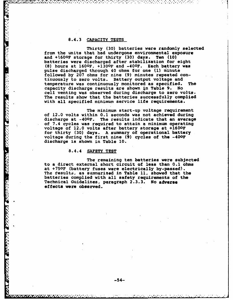
8.4.3 CAPACITY TESTS
Thirty (30) batteries were randomly selectedfrom the units that had undergone environmental exposureand +160OF storage for thirty (30) days. Ten (10)batteries were discharged after stabilization for eight(8) hours at 1600 F, +130OF and -40OF. Each battery waspulse discharged through 40 ohms for one (1) minutefollowed by 207 ohms for nine (9) minutes repeated con-tinuously to zero volts. Battery output voltage andtemperature was continuously monitored as specified. Thecapacity discharge results are shown in Table 9. Nocell venting was observed during discharge to zero volts.The results show that the batteries successfully compliedwith all specified minimum service life requirements.
The minimum start-up voltage requirementof 12.0 volts within 0.1 seconds was not achieved duringdischarge at -40OF. The results indicate that an averageof 7.4 cycles was required to attain a minimum operatingvoltage of '12.0 volts after battery storage at +1600?for thirty (30) days. A summary of operational batteryvoltage during the first nine (9) cycles of the -40OFdischarge is shown in Table 10.
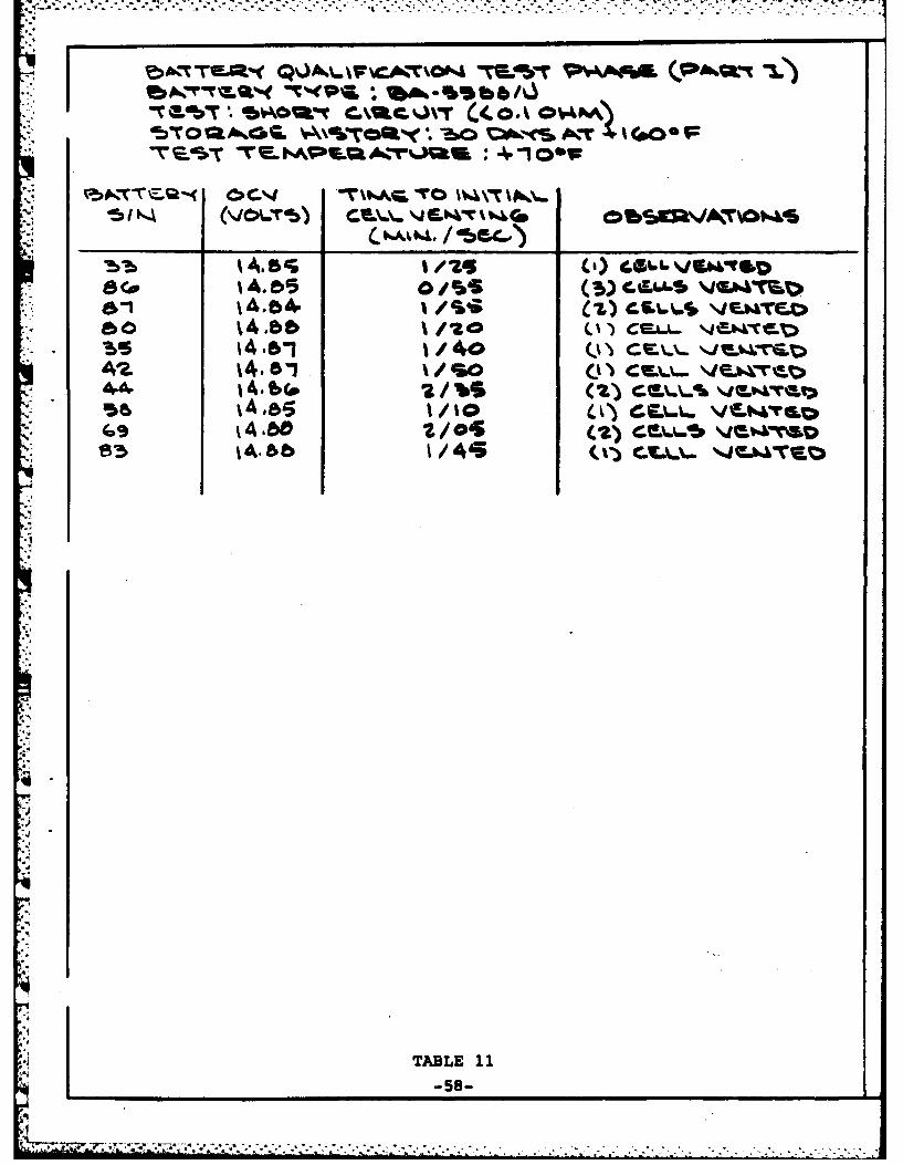
8.4.4 SAFETY TEST
The remaining ten batteries were subjectedto a direct external short circuit of less than 0.1 ohmsat +750F (battery fuses were electrically by-passed).The tesults, as suinarized in Table 11, showed that thebatteries complied with all safety requirements of theTechnical Guidelines, paragraph 2.3.3. No adverseeffects were observed.
'54-I
-54-
. ... . .

"1 %A# .%. b\,5 so VbbV6.0, %. . 331 so 5 (a,
z B \6o14.?- 54. so \Vl
4AWL 142 32.6 3 %So
k 4. .. 5 lb k - 9-14 a?.w. 14.0 3b.
".. \,. \4.0. 60.1 d0 140
O1\ 4.0,. \ " .. 30
* 45 ~ 0A%-703
+14.z 4 '.05 l ".', Z3.4 0 0 l
sz tA, 63 %4.0 50s4 s
, • ,7 ' 4."B. \3,. \'. 5 . 30-
79 tA4e8. \4-0 \4.55 k.9-55-
.. t
14to -261(
k 7 ~O 19A to 914-8 \S40b %oz 5t
15.Z 1\15l.z 1. 10
so9 \,. 1. 10 -54
43 400IC-
TABLE 9-55-

A .
0~AO CMOA ( bo"IN& A a 0V.CSV^
40( o1& 6 40 dit~ ~
'outg2 1%
7('49. \. '74 4. to.I.s2. Iz %%a I &'Z 4.
7s II-a IZ. z8 4.ab % b. 2. 86 &
4(9 bs -. ,? A2%2.
55 be-~.( . 4-
4(* 32. 1 4j-W
-740 3p MI 14. m.b
90M (90 0so I8 3t.4- soA c
* 4G.. 134
TABLE 10-56-

i t-40 k* o(1 8, vz,"ms 0G "§A 11. C2. 6WA CKW4
82. "7 12.2. 1 .1 8 ' 2. "7.. 13174,. ",9 1,9 1- 1 5.00
72. ti Z1. 13. 7. t~,"". "I 12, 1 'j.O "88 6 121 '
-bb 1Z.0 t9 6 VZ.,
,9 %%.e
79 12,0 %i.0
8?.7 9 V". 13. lY z.a s
I L9.
12.
TABLE 10 (CMt'4)
-57-
r-- - ,, - . , +..-. ' .- -+ . .. -. . . - +-.-.. . . -- . . - * + - . - .-.. - -, . ., , '~~~~~~~~~~~~~~~~~~. . . ......... .. .... . . ." "I.. .. . . ..l.l~ l l ldl lnlnlln11lnhd~ ndanl
db o a A.GC. 4qc~C o~'
(a)a
t4.6
i4.W 2/0
4--
TABLE 11
-58-
8.4.5 CONCLUSIONS:
Electrical Performance
Battery capacity exceeded all minimumservice requirements under the discharge load temperaturesafter storage at +160 0F for thirty (30) days. An averageof 7.4 load cycles (transmit/receive) were required toattain a minimum operational voltage of 12.0 volts underthe 40 ohm resistive load (transmit mode) at -400F. Itshould be noted that previous tests have indicated theability of the battery to meet start-up voltage specifi-cations at 00F.
Safety Performance
All batteries performed satisfactorilyunder the specified abusive test environments in accordancewith the requirements of the Technical Guidelines.
9. BATTERY FABRICATION PHASE - PLASTIC JACKET
in accordance with CLIN 0003 PCI fabricated and de-livered to the government BA-5588 batteries in the plasticcase housing.
10. CONCLUSIONS AND RECOMMENDATIONS
A lithium sulfur dioxide balanced cell design has beeneffected to meet the electrical physical and environmentalrequirements as specified in the Technical Guidelines.
* Five series cells have been used for the constructionof batteries which have been tested versus the followingrequirements.
Capacity before and after storage at 160OF
Start-up voltage at -40OF
Forced discharge, short circuit, temperature shock,shock, vibration and altitude.
The battery satisfied all of the electrical, physicaland environmental requirements. A final battery designincorporating a plastic case was fabricated and 500batteries were delivered to the government.
-59-

The studies performed indicated that the 100 ms,-40OF start-up requirement was beyond the capabilitiesof the system. It is recommended that the subjectspecification be modified to allow a less severe start-uprequirement.
11. ACKNO LEDGEM'ENT
The helpful suggestions and cooperation of Hr. JohnChristopulos of U.S. Army ERACOH are gratefully acknowledged.
-60-

A PP E N DIX A
STANFORD TECHNOLOGY CORP.
ENVIRONMEUAL TEST REPORT
ST - 2220
5 February 1980

STANFORD TECHNOLOGY CORP.25 PARKER AVENUE * GLENBROOK. CONN. 06U
(212) 478-2010 (203) 348-4060
REPORT OF TESTS
on
LITHIUM CELLSBA- 55 88
ENVIRONMENTAL TESTS
o
for
POWER CONVERSIONS, INC.70 MACQUESTEN PARKWAY SO.MT. VERNON, N.Y. 10550
February 5, 1980 ST-2220

t~~~~~. ... 7 1--. .'- .. .
REPORT NO. ST-2220
SIGNATURES
FOR STANFORD TECHNOLOGY CORPORATION
~1Fred Esoiq Date
Test Engineer
-Gerald T. Ciccone DateVice President
ioi

7 7777-7
REPORT NO. ST-2220
TABLE OF CONTENTS
PAGE
SIGNATURES i
TABLE OF CONTENTS i
ADMINISTRATIVE DATA iv
*FACTUAL DATA 1
1.0 TEST EQUIPMENT 1
2.0 TEST SEQUENCE AND COMPLETION DATES 2
-GENERAL SECTION3
3.0 TEST PROGRAMI 4
3.1 Temperature Shock Test 43.2 Shock Test 53.3 Vibration Test 6
APPENDIX -Test Data and Photograph 7

7=7 2..
STANFORD TECHNOLOGY CORP.TEST REPORT NO. ST-2220
ADMINIS11ATIVE DATA
TEST CONDUCTED: Temperature-Shock, Shock,
Vibration
MANUFACTURER: Power Conversions, Inc.
70 MacQuesten Parkway So.Mt. Vernon, NY 10550
MANUFACTURER'S TYPE OR MODEL NO.: BA- 5588 Cells
DRAWING. SPECIFICATION OR EXHIBIT: Technical Guidelines for PrimaryLithium Organic ElectrolyteBattery BA-5588 /U
QUANTITY OF ITEMS TESTED: Fifty (50) Cells
S/N - See General Section
,ECURITY CLASSIFICATION OF ITEMS: Unclassified
DATE TEST COMPLETED: February 5, 1980
DISPOSITION OF SPECIMENS: Returned to Power ConversionsDATE OF TEST REPORT: February 5, 1980
MANUFACTURER'S PURCHASE ORDER NO.: 9110
GOVT. CONT. NO. N/A
ABSTRACT: Refer to Test Results Sectionof this report.
.i.

REPORT NO. ST-2220
FACTUAL DATA
1.0 TEST EQUIPMENT
1.1 Temperature Chamber-' Tenney Engineering
Model: T15 UF-100240Last calibration: September 15, 1979Next calibration: March 15, 1980
1.2 High Temperature ChamberWebberModel: WF-15-l0O+350Last calibration: November 3, 1979Next calibration: May 3, 1980
N1.3 Vibration MachineMB ElectronicsModel: C-10Last calibration: September 169 1979Next calibration: March 16, 1980
1.4 AccelerometerColumbia Research LaboratoriesModel: 902Last calibration: September 16, 1979Next calibration: March 16, 1980
1.5 Band Pass FilterKrohn-HiteModel: 330NLast calibration: October 39 1979Next calibration: April 3, 1980
1.6 OscilloscopeTektronix, Inc.Model: 564 BLast calibration: October 39 1979Next calibration: April 3, 1980
1.7 Integrator AmplifierMB ElectronicsModel: N-504Last calibration: September 16, 1979
Next calibration: March 16, 1980
1.8 Shock MachineAvco Research & Development Corp.Model: SM-l10Calibration: Before each use
REPORT NO. ST-2220
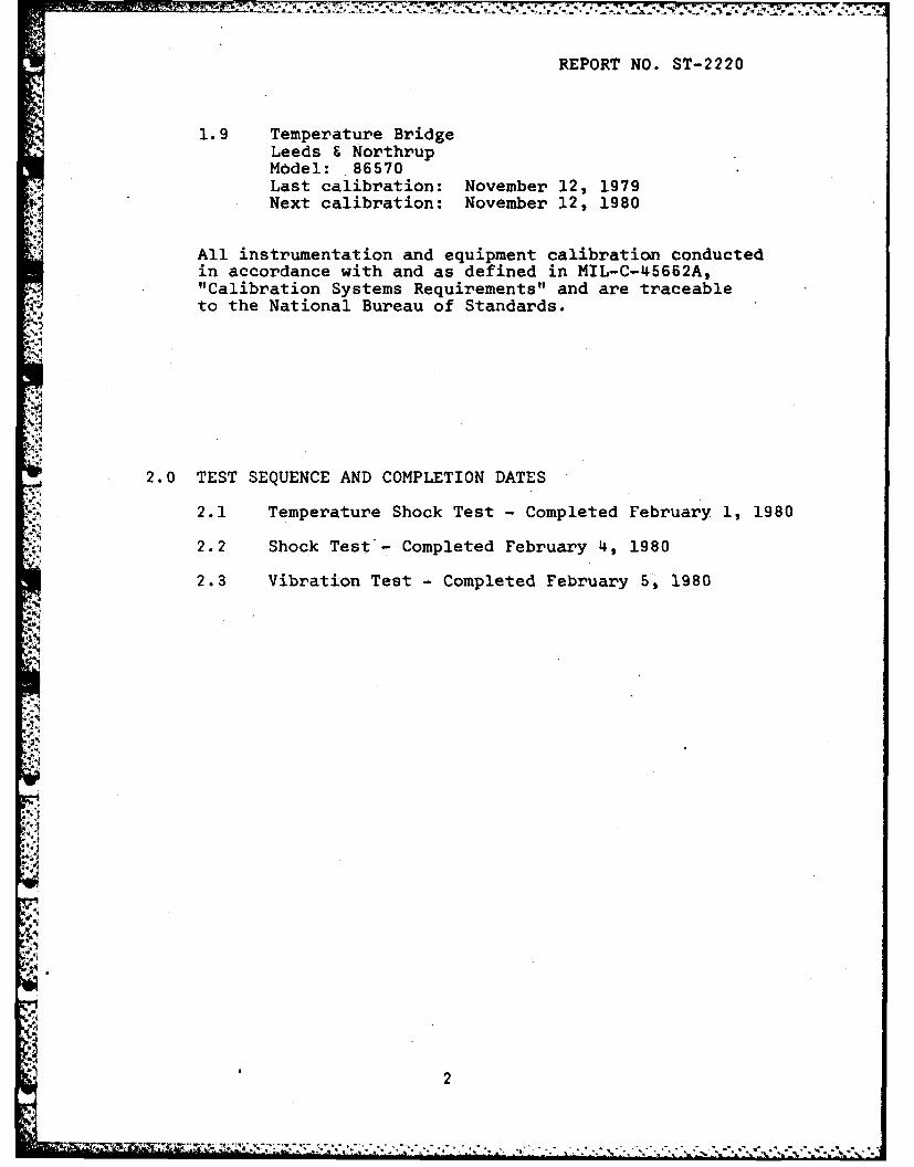
1.9 Temperature BridgeLeeds & NorthrupModel: 86570Last calibration: November 12, 1979Next calibration: November 12, 1980
21 All instrumentation and equipment calibration conductedin accordance with and as defined in MIL-C-45662A,
* "Calibration Systems Requirements" and are traceableto the National Bureau of Standards.
2.0 TEST SEQUENCE AND COMPLETION DATES
2.1 Temperature Shock Test - Completed February 1, 1980
2.2 Shock Test - Completed February 4, 1980
2.3 Vibration Test - Completed February 5, 1980
i2

REPORT NO. ST-2220
GENERAL SECTION
Serial Numbers of the fifty (50) BA-5588 Cells tested.
76 39 65 89 74
21 40 31 72 591 69 56 10 so
62 88 58 28 3
92 37 32 5 47
11 70 87 3 45
38 73 54 24 42
219 66 23 20 12
75 96 51 78 43
49 30 29 17 53
j
'43

REPORT NO. ST-2220
3.0 TEST PROGRAM
3.1 Temperature Shock Test
3.1.1 Test Procedure
The Temperature Shock Test was conducted inaccordance with MIL-STD-810C, Method 503.1, withthe exception that five (5) cycles were performedand Step 9 was omitted.
Step 1 - The Cells were initially placed with a hightemperature chamber which had been previously stabi-lized at +160 F, and maintained at this temperaturefor a period of not less than four (4) hours.
Step 2 - The Cells were then transferred within five(5) -minutes to a low temp8rature chamber with an in-ternal temperature of -70 F, and maintained at thistemperature for a period of not less than four (4)hours.
At the completion of the low temperature period, theCells were again transferred to the high temperature
chamber within five (5) minutes.
Steps 1 and 2 constituted one (1) cycle of tempera-ture shock. A total of five (5) cycles were performed.
At the completion of the entire Temperature ShockTest, and after stabilization at room ambient condi-tions, the Cells were visually examined for evidenceof cracking, rupture, leakage, deterioration orcorrosion.
3.1.2 Test Results
There was evidence of leakage to Cell Serial Number69 as a result of this test. All other Cells ex-
hibited no evidence of cracking, rupture or leakage.
4
• . . . . . . . - . . ...

REPORT NO. ST-2220
3.2 Shock Test
3.2.1 Test Procedure
The Shock Test was conducted in accordance withMIL-STD-810C, Method 516.2, Procedure I, Figure516.2-2, for ground equipment.
The Cells were securely fastened to the table ofa shock machine and subjected to a total of eighteen
2 (18) shock impacts. Each shock pulse approximated ahalf sine wave having a peak amplitude of 30 g's anda nominal time duration of eleven (11) milliseconds.
*1 Three (3) shocks were applied in each direction alongeach of three (3) mutually perpendicular axes.
At the completion of the Shock Test, the Cells werevisually examined for evidence of physical damage orleakage.
3.2.2 Test Results
There was no visual evidence of physical damage orleakage as a result of this test. Serial Number 69was not tested.
J5

REPORT NO. ST-2220
3.2 Vibration Test
3.2.1 Test Procedure
The Vibration Test was conducted in accordance withMIL-STD-810C, Method 514.2, Procedure X, EquipmentE, Curve AW, non-operating.
The Cells were securely fastened to the table of avibration machine and subjected to the followingconditions.
The Cells were subjected to sinusoidal cycling ata logarithmic rate between the frequency limits andat the vibratory acceleration levels specified inTable I, for a period of eighty-four (84) minutes
in each of the three (3) mutually perpendicular axes.No resonances were observed.
TABLE I
VIBRATION TEST LEVELS
Frequency Displacement/(Hz) Acceleration
5-200 1.5 g pk
At the completion of each axis of vibration, theCells were visually examined for evidence ofphysical damage or leakage.
3.2.2 Test Results
There was no visual evidence of physical damage orleakage as a result of this test. Serial Number 69was not tested. The Cells were returned to PowerConversions, Inc. for evaluation.
6
, 7., . . . . . . . . . . . .

REPORT NO. ST-2220
APPENDIX
Test Data and Photograph
7

REPORT NO. ST-2220STANFORD TECHNOLOGY CORP.
TEST DATA SHEET
Test Condition /-2 _ Date Job. No.
Specification Para. No. Test Operator
Test Item Part No. Approved by
6:; / .32 5/ / 5 ~ _ _ _ _ _ _
-xi / ZLZ ZL 3 _______ _
'j r ___ 92_ __ _
L Zi. " : ,_ __ , ___/_ _ _
/3 _____- V
04f
') / JZ:L ._ _ __ _ _ __ __ _ __ _ _ _ _
8

*. . . . . . . . .. . . .
REPORT NO. ST-2220
TYIA HC ULEPOORP
Caibato
10gsdvsin vria2 sdvson hrzna
.49

APPENDIX B
ALTITUDE TEST RESULTS
BA-5588/U CELLS
Power Conversion, Inc*Mount Vernon, N4Y 10550
February 1980
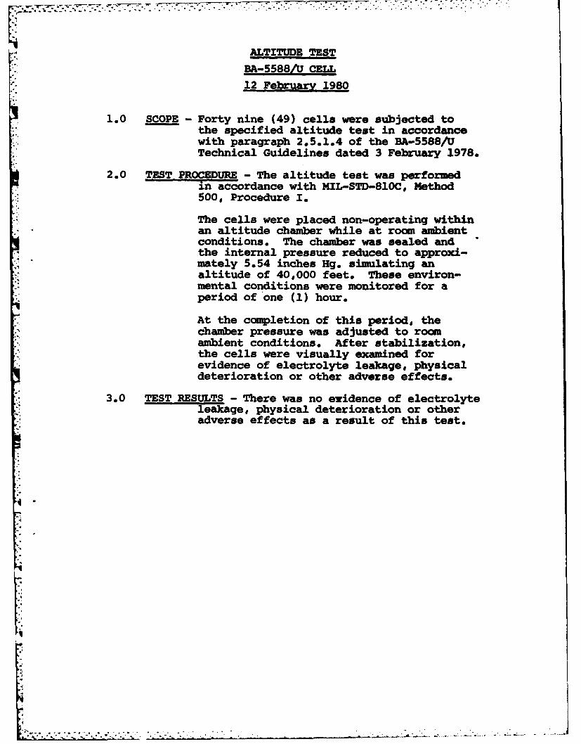
ALTITUDE TESTBA-558=/ CELL12 February 1980
1.0 SCOPE -Forty nine (49) celia were subjected tothe specified altitude test in accordancewith paragraph 2,5.1.4 of the BA-.5588/UTechnical Guidelines dated 3 February 1978.
2.0 TEST PROCEDURE - The altitude test was performedin accordance with MIL-STD-810C, Method500s Procedure I.
The cells were placed non-operating withinan altitude chamber while at room ambientconditions. The chamber was sealed andthe internal pressure reduced to approxi-mately 5.54 inches Hg. simulating analtitude of 40,000 feet. These environ-mental conditions were monitored for aperiod of one (1) hour.
At the completion of this period, thechamber pressure was adjusted to roomambient conditions. After stabilization,the cells were visually examined forevidence of electrolyte leakage, physicaldeterioration or other adverse effects,
3.0 TEST RESULTS - There was no evidence of electrolyteleakage, physical deterioration or otheradverse effects as a result of this test.

APPENDIX C
STANFORD TECHNOLOGY CORP.
2 ENVORIMONMENTAL TEST REPORT
ST-2398-OOC
29 May 1980
4
SSTANFORD TECHNOLOGY CORP.25 PARKER AVENUE * GLENBROOK. CONN. 06906
(212) 478-2010 (203) 348-4080
REPORT OF TESTS
on
LITHIUM CELLSBA-5588/U
ENVIRONMENTAL TESTS
FOR
POWER CONVERSION, INC.70 MACQUESTEN PARKWAY SO.
MT. VERNON, N.Y. 10550
May 29, 1980 ST-2398-OOC

" It NA 'IU iR:S
FOR STANI'ORI) TECHNOLOGY CORPORATION
jerilior, Pro(ject Enigineer
0',er a -1(FT 71c ro ne D'siVicc' President

*7 .d .2
REPORT NO. ST-2398-OOC
TABLE OF CONTENTS
PAGE
SIGNATURES ii
TABLE OF CONTENTS iii
ADMINISTRATIVE DATA iv
TABLE I- Identification of Test Units v
FACTUAL DATA 1
1.0 TEST EQUIPMENT 1
2.0 TEST SEQUENCE AND COMPLETION DATES 2
S. 3.0 TEST PROGRAM 3
3 3.1 Temperature Shock Test 33.2 Shock Test 43.3 Vibration Test 5
FIGURE 1 -Calibration Photograph 6
*1
.,
.9
-a
iii

,,1
STANFORD TECHNOLOGY CORP.TEST REPORT NO. ST-2398-OOC
ADMINISTRATIVE DATA
TEST CONDUCTED: Temperature-Shock, Shock, Vibration
MANUFACTURER: Power Conversions, Inc.70 MacQuesten Parkway So.Mt. Vernon, NY 10550
MANUFACTURER'S TYPE OR MODEL NO.: BA-5588/U Cells
Technical Guidelines for PrimaryDRAWING, SPECIFICATION OR EXHIBIT:;, Lithium Organic ElectrolyteBattery BA-5588()/U, dated 2/3/78
QUANTITY OF ITEMS TESTED: Forty-one (41) CellsS/N - See Table I
SECURITY CLASSIFICATION OF ITEMS: Unclassified
DATE TEST COMPLETED: May 29, 1980
" DISPOSITION OF SPECIMENS: Returned to Power Conversions
, DATE OF TEST REPORT: May 29, 1980
MANUFACTURER'S PURCHASE ORDER NO.: 9724
GOVT.CONT.NO. N/A
ABSTRACT: Refer to Test Results Sectionof this report.
i
iv
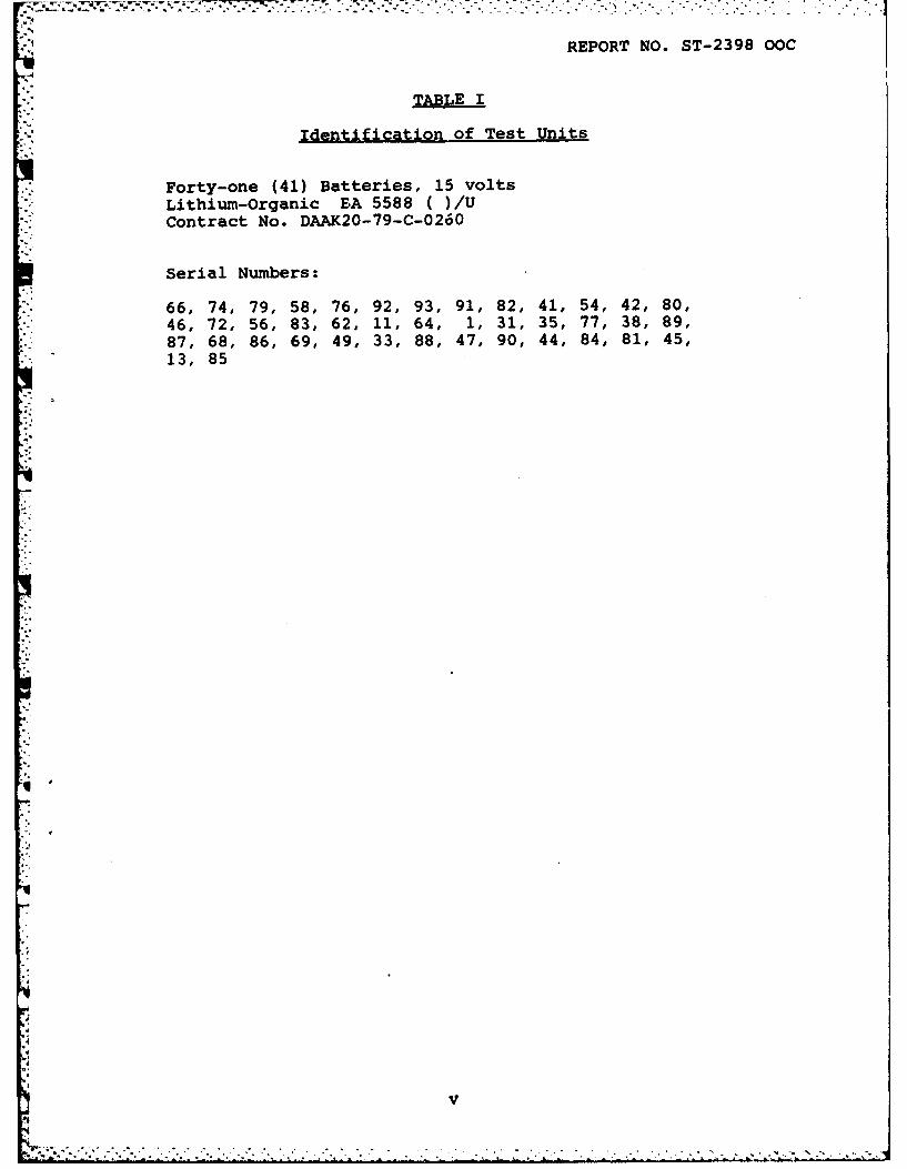
REPORT NO. ST-2398 OOC
* TABLdE I
Identification of Test Units
Forty-one (41) Batteries, 15 voltsLithium-Organic BA 5588 ( )/UContract No. DAAK20-79-C-0260
Serial Numbers:
66, 74, 79, 58, 76, 92, 93, 91, 82, 41, 54, 42, 80,46, 72, 56, 83, 62, 11, 64, 1, 31, 35, 77, 38, 89,87, 68, 86, 69, 49, 33, 88, 47, 90, 44, 84, 81, 45,13, 85
*q,
.4

REPORT NO. ST-2398-OOC
FACTUAL DATA
1.0 TEST EOUIPMENT
1.1 Temperature ChamberTenney EngineeringModer. T15 UP-100240Last Calibration: March 15, 1980Next Calibration: September 5, 1980
1.2 High Temperature ChamberWebber Eng.Model: WF-15-100+350Last Calibration: May 3, 1980Next Calibration: November 3, 1980
1.3 Vibrattgn MachineMB ElectronicsModel: C-10Last Calibration; March 16, 1980Next Calibration: September 16, 1980
1.4 AccelerometerColumbia Research LaboratoriesModel: 902Last Calibration: January 5, 1980Next Calibration: July 5, 1980
1.5 Band Pass FilterKrohn-HiteModel: 330NLast Calibration: October 3, 1979Next Calibration: October 3, 1980
1.6 OscilloscopeTektronix, Inc.Model: 564BLast Calibration: March 24, 1980Next Calibration: September 24, 1980
1.7 Integrator AmplifierMB ElectronicsModel: N-504Last Calibration; March 16, 1980Next Calibration: September 16, 1980
1.8 Shock MachineAvco Research & Development Corp.Model; SM-110Calibration: Before each use.
--- J J " ' " ' "'" .'° ' '." ' .,-" ° , . =" " ""-- -"""" ',- .'"" """ "" ""- ,. " " "" " " "°1

REPORT NO. ST-2398-OOC
1.9 Temperature BridgeLeeds & NorthrupModel: 8693Last Calibration; May 7, 1980Next Calibration: November 7, 1980
All instrumentation and equipm~ent calibration conductedin accordance with and as defined in MIL-C-45662A,"Calibration Systems Requirements"~ and are traceabletc the National Bureau of Standards.
2.0 TEST SEQUENCE AND COMPLETION DATES
2.1 Temperature Shock Test - Completed May 22, 1980
2.2 Shock Test - Completed May 28, 1980
2.3 Vibration Test -Completed May 29, 1980
2
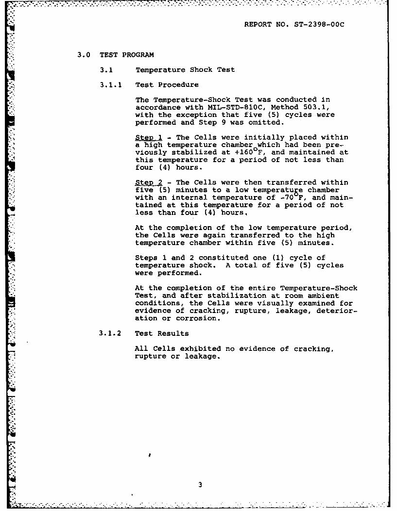
REPORT NO. ST-2398-OOC
3.0 TEST PROGRAM
3.1 Temperature Shock Test
3.1.1 Test Procedure
The Temperature-Shock Test was conducted inaccordance with MIL-STD-810C, Method 503.1,with the exception that five (5) cycles wereperformed and Step 9 was omitted.
Step 1 - The Cells were initially placed withina high temperature chamber which had been pre-viously stabilized at +160 F, and maintained atthis temperature for a period of not less thanfour (4) hours.
Step 2 - The Cells were then transferred withinfive (5) minutes to a low temperatuge chamberwith an internal temperature of -70 F, and main-tained at this temperature for a period of notless than four (4) hours,
At the completion of the low temperature period,the Cells were again transferred to the hightemperature chamber within five (5) minutes.
Steps 1 and 2 constituted one (1) cycle oftemperature shock. A total of five (5) cycleswere performed.
At the completion of the entire Temperature-ShockTest, and after stabilization at room ambientconditions, the Cells were visually examined forevidence of cracking, rupture, leakage, deterior-ation or corrosion.
. 3.1.2 Test Results
All Cells exhibited no evidence of cracking,rupture or leakage.
-. 3
- a
04
N3
* .' . 2 , . . ,
- . - .':--. , . ' ' ',* " ' ,".... .. . "... . ... . . " L ".. " * -.. " . ... "*. " ' . '

REPORT NO. ST-2398.-OOC
3.2 Shock Test
3.2.1 Test Procedure
The Shock Test was conducted in accordance withMIL-STD-B1OC, Method 516.2, Procedure I, Figure516.2-2, for ground equipment.
The Cells were securely fastened to the table ofa shock machine and subjected to a total ofeighteen (18) shock impacts. Each shock pulseapproximated a half sine wave having a peakamplitude of 30 g's and a nominal time durationof eleven (11) milliseconds. Three (3) shockswere applied in each direction along each of thethree (3) mutually perpendicular axes.
At the completion of the Shock Test, the Cellswere visually examined for evidence of physicaldamage or leakage.
3.2.2 Test Results
There was no visual evidence of physical damage
or leakage as a result of this test.
4

REPORT NO. ST-2398-OOC
3.3 Vibration Test
3.3.1 Test Procedure
The Vibration Test was conducted in accordancewith MIL-STD-810C, Method 514.2, Procedure X,Equipment E, Curve AW, non-operating.
The Cells were securely fastened to the table ofa vibration machine and subjected to the followingconditions.
The Cells were subjected to sinusoidal cycling ata logarithmic rate between the frequency limitsand at the vibratory acceleration levels specifiedin Table I, for a period of eighty-four (84)minutes ±n each of the three (3) mutually perpend-icular axes. No resonances were observed.
TABLE I
Vibration Test Levels
Frequency Displacement/(Hz) Acceleration
5-200 1.5 g pk.
At the completion of each axis of vibration, theCells were visually examined for evidence ofphysical damage or leakage.
3.3.2 Test Results
There was no visual evidence of physical damageor leakage as a result of this test. The Cellswere returned to Power Conversion, Inc. forevaluation.
5

A -Ri28 858 PRIMARY LITHIUM ORGANIC ELECTROLYTE BATTERY BR-55B9(U) 2/2POWER CONVERSION INC ELMWIOOD PARK NJ M G ROSANSKYJUL 82 DELET-TR-79-8266 F DAAK28-79-C-8268
UNCLASSIFIED F/G 8/3 NLI.E.E.E

K'HIS
11.
L-M
MICROCOP MiNMwo TEST CHARTMICROCOPY RESOUTION TEST CHART H ATIOW UMEA OF NOW10ifUS4
MilOIL BUIM Of STANiOMD-1963-A
.
VICROCOPY -EOUTO TEST CHART
LII ml.I Mi
1 -W ILL6 1.J,
11In.w mlI if IiMS-U- diSW SWIM I INS

REPORT NO. ST-2398-OOC
(30 gas, 11.0 ms, sine)
Vertical Sensitivity: 5.0 g's/major divisionHorizontal Sensitivity: 2.0 m/major division
Calibration PhotoaraDh of Shock Pulse
6
.._ . ... Z-5 WI
*1
APENDIX D
ALTITUE TEST RSULTS
EA-5588/U BATTERY
Power Conversion, Inc.
Mount Vernon, N.Y. 10550
3 June 1980
2.1
. -,vI...*---

!,,
1-*0 r6t (40) betteries were subjected tot1W 40ecified altitude test in accordancerith penwrapt 2.5.1.4 of the BA-SSS/UTochnical Gieline. dated 3 February 1978.
2.0 = PW O - The altitude test was performed14, tccorfnce with ?N4L-STD-8l0C, Method500, Procedure I.
rThe batteries ware placed non-operatingwithin tn altitude chamber Vhile at roosmambiet bonditions. T .chamber was sealedan the internal jprenstte reduced to approxi-Mati@Y + 5.4 inches Hg. simulating an-altitude of 40000 feet. These, eniron-nattZ ',odties were monitored for ap eriod of 6fte (1) hour.
At the io of this period, the
*O~tn* fmtiotz. Mfter stabilization,tig bittaitn wer visually easwinG forevidence of electrolyte leakage, pbysicaldeterirtion or other adverse effects.
3.0 W- Tre was to evidence of electrolyter0scal dtertoration or other
adterf effets as a result of this test.
DISTRIBUTION LIST
Defense Technical Info Ctr DirectorATTN: DTIC-TCA- US Materiel Sys Anal ActyCameron Station (Bldg 5) ATTN: DRXSY-TAlexandria, VA 22314 (12) Aberdeen Prov Grnd, ND 21005 (1)
Director PH, FIREFINDER/REMBASSNaval Research Laboratory ATTN: DRCPK,-FERATTN: Code 2627 Fort Monmouth, NJ 07703 (2)Washington, DC 20375 (1)
Cdr, Project Manager, SOTASCdr, Naval Surface weapons Ctr ATTN: DRCPN-STAWhite Oak Laboratory Fort Momouth, NJ 07703 (1)ATTN: Library, Code WX-21Silver Spring, NO 20910 (1) Cdr, US Amy Research OfficeCATTN: DRXRC-PH (Dr. R.J. Lontz)Commandant, 11arine Corps PO Box 12211HQ, US Marine Corps Rsch Triangle Pk, NC 27709 (2)TTi Code %i (In Turn)wash ngton, Commander, DARCOMCommand, Control & Com Div. ATTN: DRCDEDevelopment Center 5001 Eisenhower AveMarine Corps Dev & Educ Cnd Alexandria, VA 22333 (1)Quantico, VA 22134 (1)
Cdr, USA Signals Warfare LabRome Air Development Center ATTN: DELSW-OSATTN: Documents Library (TSLD) Vint Hill Farms StationGriffiss AFB, NY 13441 (1) Warrenton, VA 22186 (1)
AFGL/SULL CommanderS-29 USA obility Eqp Res & Dev CmdHAFB, MA 01731 (1) ATTN: DRDNE-R
Fort Belvoir, VA 22060 (1)CommanderHQ, Fort Huachuca Cdr, NV&EOL, ERADCONATTN: Technical Reference Div ATTN: DELNV-DFort Huachuca, AZ 85613 (1) Fort Belvoir, VA 22060 (1)
Deputy for Science & Technology Cdr, Atmospheric Sciences LabOffice, Asst Sec Amy (R&D) ERADCO,Washington, DC 20310 (1) ATTN: DELAS-SY-S
White Sands Missile Rng N*1 (1)HQDA (WM-ARZ-D/Dr. F.D. Verderame) 88002Washington, IC 20310 (1)
Cdr, Harry Diamond LabsCdr, Harry Dimond Laboratories ATTN: DELHI-CO, TO (In Turn)ATTN: Library 2800 Powder Mill Road2800 Powder MillI Road Adelphi, 1MN 20783 (1)Adelphi, MD 20783 (1)

• -- - -. .L* ur.,I .7 -7 - -. -- --- -. -7 . . v . a °
DISTRIBUTION LIST- Continued
Cdr, ERADCON TACTECATTN: DRDEL-CG, CD, CS (In Turn) Battelle femorial Institute2800 Powder Mill Road 505 King AvenueAdelphi, HD 20783 (1) Columbus OH 43201 (1)
Cdr, ERADCON Union Carbide CorporationATTN: DRDEL-CT ATTN: Mr. R. Powers2800 Powder Hill Road 12900 Snow RoadAdelphi, MO 20783 (2) Parma, OH 44130 (1)
Cdr, ERADCOM Duracell International Inc.ATTN: DRDEL-PA ATTN: Mr. Eugene Errico2800 Powder Mill Road South BroadwayAdelphi, NO 20783 (1) Tarrytown, N.Y. 10591 (1)
Cdr, ERADCOM Honeywell, Inc.ATTN: DRDEL-IL-S ATTN: Mr. T. Whittaker2800 Powder Mill Road 104 Rock RoadAdelphi, MD 20783 (1) Horsham, PA 19044 (1)
Commander ESB, Inc.US Army Electronics R&D Command Ray-O-Vac DivisionFort Monmouth, NJ 07703 ATTN: Mr. P. Albert
212 East Washington AvenueDELET-DD (0 Madison, WI 53703 (1)DELET-DI 1lDELSD-L (Library) ( Eagle Picher Industries, Inc.DELSD-L-S (Stinfo) 2 Electronics DivisionDELET-PB (Mr. Christopulos) ( Couples Department
P. O. Box 47Commander, CECOM Joplin, MO 64801 (1)Fort Monmouth, NJ 07703
GTE SylvaniaDRSEL-COM-RN-3 (J. Lee) 1) 529 Winter StreetDRSEL-LE-CR-l (J. Bigas) (1) Waltham, MA 02154
ATTN: Dr. Ronald McDonald (1)MIT Lincoln LaboratoryATTN: Library (Rm A-082) Altus Corp.Lexington, MA 02173 (2) ATTN: Mr. D.K. Snuggerud
1610 Crane CourtNASA Scientific & Tech Info San Jose, CA 95112 (1)FacilityBaltimore/Washington Intl Airpt Saft Corp of AmericaPO Box 8757, MD 21240 (1) ATTN: Mr. Lou Adams
711-A Industrial Blvd.National Bureau of Standards Valdosta, GA 31601 (1)Bldg 225, I M A-331ATTN: Mr. Leedy Electrochem Industries, Inc.Washington, DC 20231 (1) ATTN: Dr. C.C. Liang
9990 Wehrle DriveAdvisory Group on Electron Clarence, NY 14031 (1)Devices201 Varick St., 9th Floor Sanders AssociatesNew York, NY 10014 (2) ATTN: Mr. D. Dwyer
95 Canal Street,Nashua, NH 03061 (1)
., tl " ' l-
7 .

DISTRIBUTION LIST -continued
Project Manager, TACFIRE/FATDSATTN: DRCPN-TFFort Momunuth, NJ 07703 (1)
ComandantUS Marine CorpsATTN: LNC-4 (Mr. R. Oderwald).Washington, DC 20380()