Embed Size (px)
Citation preview
imrarCTT— - •' ■ ^HffrT"" • -f'Tirr m i rtmr -11111(111 '.mmniiiinmimp^
• •
AD-A017 101
INVESTIGATION OF THE PERFORMANCE OF PERSONAL FLOTATION DEVICES
Underwriters Laboratories, Incorporated
Prepared for
Coast Guard
August 1975
DISTRIBUTED BY:
um National Technical Information Service U. S. DEPARTMENT OF COMMERCE
. . , „I, frumümiiMii 1 1 ,.—M—^I^M—— MM^M^Mi
'^'-T'-^iiiT'iliii'miiMfit^

r····-
Best Available
Copy
. '
1' "■ ■""■■ '"
322071
\
t«port No. CG-M68-75
INVESTIGATION ff Tf€ fOTWATICE OF
PERSTTJAL FLOTATinN DEVICES
O rH
FiriAL REPORT
AUGUST 1075
n D'cv
iii
Document is available to the public through the National Technical Information Service,
Springfield, Virginia 22161
Pr«por«d for
DEPARTMENT OF TRANSPORTATION UNITED STATES COAST CUARD Offlc« of ■•••arch and D«v«lopm«nf
Wathingtan, D.C. 20590 Rppruduced by
NATIONAL TECHNICAL INFORMATION SERVICE
US D«p»rtiMnt of Comm«e« Spurgfield, VA. 22151
e i
-- ■ am ■ - -—- - ■■-■■ - - ■ ■ ■, ' IMJ

mmm ^^^mmmmmmm ■^^^■^■^ i mm ■ "•"* "" ■■'■' - ■■ ' wim --^
.-,.■■#..-..-r ..'» . .• ►>^«i ••mmv**! *lfmvt ■
Ttchnical Report Documentation Pogt
Gov9rnm*nl A cce»»io» No. I. Rvpoft No
CG-D-168-75 4. Till« and Subti'l«
Investigation of the Performance of Personal Flotation Devices
j Rtctp«»nf't Catalog No.
i Rtpo'i da'»
August 1975 6 P»rfo'ming O'gon.io'on Cod«
7 AuthO'1!'
9. P»#fo'mtnj Orgorti ia*ion Nam» ona Add'»»«
Underwriters Laboratories, Inc. Tampa, Florida
12. Spontormg Agency Nom« and Add'»»*
U. S. Coast Guard (G-DST) Washington, D. C.
8. Parfo'fn.ng Organiiatton Rtport No.
10 Wo'k Un.l No (TRAISI
35-03 1 I Controc* O' Grant No.
DOT-CG-25112-A 13 Typ« o< Rvpor) and P«nod Co»«'«d
Final
14. Sponiormg Agency Cod*
15 Supptamvntory No*tl
16. Abtttoct An experimental investigation was performed to study various aspects of an
existing theory for flotation equilibrium angle of a person wearing a personal flotation device (PFD) in water (Reference 1). The major objectives were determination of the validity of the theory, and derivation of a method for determining the buoyant force and center of buoyancy of a PFD when worn by a person. Additionally, information was obtained on the sensitivity of the theory to small changes in variables, the variability of repetitive measurements of certain human-body characteristics required by the theory (namely, lung vector and intrinsic stiffness vector), the variation with time of day of an individual's intrinsic stiffness vector, and the comparative effectiveness of five PFD's. The experiments used eight human subjects (130-240 lbs. in weight), five PFD's, and five different times of day. Because of the small number of experiments used, the statistical älgnlficance of some results is limited.
A recommended approach to evaluating PFD effectiveness using experiments with mannequins is described.
PRICES SUBJECT TO CHANGE 17, Kay Word,
Personal Flotation Device
18, Distribution Stattment
Document is available to the public through the National Technical Information Service, Springfield, VA.
22161
19, Secunly Clottil. (ol 'hit rapo't)
Unclassified
20. Sacu'ity Cloifif. (of this page)
Unclasslfiedi
I
21. No. of Pog«» 22, Pne«
Form DOT F 1700.7 (8-72) Reproduction of completed page authorized
■■ •■ ■■■ ■■- -■• ■ ■ ■' —..?-■..•—i.-i ■ ■■■Ml»» It* I . -u.. -^ , ■ .- ■ .^ - ^M|M,M,^MM. ■-..■ ■■ UMIMW ■mi ^innniyifriiygiiiiiiii^^
r '-— ,.,„...„**,*.. „,.„..
»i W-Tunngf MiTMfi^' f '■■.■■■
6 OCT 1975
The work reported herein was accomplished for the U. S. Coast Guard's Office of Research and Development, Marine Safety Technology Division, as part of Its program In Recreational Boating Safety.
The contents of this report reflect the views of Underwriters Laboratories, Inc., Tampa, Florida, who are responsible for the facts and the accuracy of the data presented herein. The contents do no necessarily reflect the official views or policy of the Coast Guard. This report does not constitute a standard, specification or regulation.
D. MARKLE, ^R., CAPTAIN, USCG Chief, Marine Safety Technology Division Office of Research and Development U. S. Coast Guard Headquarters Washington, D. C. 20590
II
r >
ii i l,IM,lll<l,Mlgll<llllttlll

f^H^ , """■--"■'""■'™-^— ■ ■'- _.,_-, _..- ..
FINAL REPORT ON
INVESTIGATION OF THE PERFORMANCE OF PERSONAL FLOTATION DEVICES
Submitted to the
DEPARTMENT OF TRANSPORTATION
UNITED STATES COAST GUARD
WASHINGTON, D. C.
Under Contract
D0T-CG-(o5-ll^-A
August 1975
Underwriters Laboratories Inc, Tampa Florida
i\
-■"-- ■"■- — "—■■■..-'■—..-■■-^ .-..-. ...^,...... .. . .. ^

TABLE OF CONTENTS Page
ABSTRACT
List of Tables ix List of Figures x
I. INTRODUCTION 1-1
II. EXPERIMENTAL AND COMPUTATIONAL METHODS II-l
A. Flotation Test Schedule and Subjects II-l
1. Determination of lung volumes appropriate to the flotation theory II-2
2. Determination of intrinsic stiff- ness vector II-2
3. Determination of equilibrium angle and PFD emergence with subject wearing a specific PFD II-3
B. Determination of the Effective Buoyancy and Center of Buoyancy of PFD Worn by a Specific Subject
III. RESULTS AND DISCUSSION
A. Intrinsic Stiffness Vector
1. Representativeness of sample of eight subjects
2. Variation of ISV with Time of Day
B. Lung Vector
C. Equilibrium Flotation Angle of Subjects and Various PFD's
1. Comparison of observed and calcu- lated equilibrium angles
2. Sensitivity analysis of flotation theory
D. Comparative Effectivenesses of PFD's
E. Effect of PFD Emergence on Equilibrium Flotation Angle
vli
II-4 :
III-l
III-l
III-l
III-5
i
III-8
111-10
,;■
111-10
111-13
111-19 ■.
111-22
■ ■■■■:-^.-—■■■■ --.^..
' ■'- ^--■-.--^-—--. ..■...---■. ....... -:..:.*

mmmmmm mm ■ ■■ 11 11^
Table of Contents (Cont'd)
IV. CONCLUSIONS
V. RECOMMENDATIONS
VI. TABLES AND FIGURES
VII. REFERENCES
IV-1
V-l
VI-1
VII-1
APPENDICES
A. Flotation Theory and Definitions A-l
B. Example of Determination of Equilibrium Flotation Angle B-l
C. Computer Programs and Subroutines C-l
D. Sensitivity Analysis of Flotation Theory D-l
\j i\i
. — ^^1^^^^.^m^^^^..—

miimmmm^r*'mmmrmmi^iimmmmr~" ' ' •■ip.«.iiiiii p.ni.iP.il.,iiii n. i u I.,.II...
^
TABLES
Table No. Title Page
1 Physical Characteristics of Subjects VI-1 2 Test Schedule VI-2 3 Intrinsic Stiffness Vector (ISV) VI-3 4 Comparison of Intrinsic Stiffness Vectors- VI-4 5 Standard Deviations of ISV Magnitudes
and Phase Angles for Eight Subjects at Various Times of Day and for 76 Subjects from Reference 1 VI-5
6 90 Percent Confidence Intervals for the Ratio of Standard Deviations of Present Data and Reference 1 Data for ISV VI-6
7 Standard Deviations for the ISV of Subject 3 in Three Replicate Experiments VI-7
8 95% Confidence Intervals for the Standard Deviation of Replicate Measurements of the ISV of Subject 3 VI-7
9 Standard Deviations of the Magnitude and Phase Angle of ISV for Each Subject Over 5 Different Times of Day VI-8
10 Lower 90 Percent Confidence Limits on the Ratio S^/S for Six Subjects VI-9
11 Variation in Lung Vector for Test Subject No. 3 VI-10
12 Summary of Calculated and Observed Results VI-11 13 Errors in Calculated Equilibrium Angle
Associated with Errors in ISV and LV Measurements for Subject 3 VI-12
14 Errors in Calculated Equilibrium Angle Associated with Errors in BV and LV Measurements for Subject 3 VI-12
15 Observed Equilibrium Flotation Angles VI-13 16 Buoyancy Vectors for Personal Flotation
Devices VI-14 17 Percent of Available Buoyancy Used by
Each PFD to Support Test Subject at Observed Equilibrium Flotation Angle VI-15
ix
^.i—...^ .., ,.r;.....-.».H,., .„....^..L...,,...^^^..-,..-..,..,....^. .■■.-,..—„.^.i,,....,.^,.■■■„I..,.I„. .,, ,.,„.■ ....■.,..,■... ,,, ^.YiiiiifitiMiiiiiiiiiaiiiiiiiii^^ i

■HUP ■■«111111II ■ -■ " I
FIGURES
Figure No.
1 2 3
4 5
C-l C-2A C-2B C-2C C-3 C-4
C-5
C-6
D-l
D-2
Title Page
Five Types of PFD's VI-16 Test Apparatus VI-17 Schematic Representation of the Technique
for Determining Buoyancy and Center of Buoyancy of Partially Emerged PFD's VI-18
Schematic Diagram of Partially Emerged PFD-VI-19 Schematic Representation of Limiting
Values of the Buoyancy Vector VI-20
CG as Affected by Above-Water Torso C-15
Illustrations of Calculations of CB and CG-C-16
Schematic of PFD-Torso Frame System C-l7 Schematic for Determination of Vertical
Location of CB of Partially Emerged PFD (A>0) —-C-18
Schematic for Determination of Vertical Location of CB of Partially Emerged PFD (A^O) C-19
Schematic for Determining CG of Buoyant Device C-20
Determination of Resultant Stability Vector-Head Forward D-6
Determination of Resultant Stability Vector-Head Back D-7
m. ■ ■ — - -.-—■ *...... mm f-—'■■'"
' m
mmmm mmm m-mt
ABSTRACT
An experimental investigation was performed to study various aspects of an existing theory for flotation equilibrium angle of a person wearing a personal flotation device (PFD) in water (Reference 1) . The major objectives were determination of the validity of the theory, and derivation of a method for determining the buoyant force and center of buoyancy of a PFD when worn by a person. Additionally, information was obtained on the sensitivity of the theory to small changes in variables, the varia- bility of repetitive measurements of certain human-body characteristics required by the theory (namely, lurg vector and intrinsic stiffness vector), the variation with time of day of an individual's intrinsic stiffness vector, and the comparative effectiveness of five PFD's. The experi- ments used eight human subjects (130-240 lbs. in weight), five PFD's, and five different times of day. Because of the small number of experiments used, the statistical significance of some results is limited.
A recommended approach to evaluating PFD effectiveness using experiments with mannequins is described.
I ;
Xi
in i ■-- ^^^^«^B

.„_.._. „.„r^_.,_.™, „ „„„- -..^.-,.,,,T,^- .-^,By^rWtm.-^yl,n|W»i^./pi.i.i^ii m^JHiiPWHUt»! tmymW^rr-
WWMJIWM—oiii w» ^WWMWWWWW inpuDint^^wilW ^■'f^'W^-V^lW^^
*
I INTRODUCTION
A previous study (1)* prepared a data base for
predicting the performance of personal flotation devices
(PFD's) applied to the general population. The study WöS
directed toward providing data on the flotation charact-
eristics of 200 subjects selected from the boating pop-
ulation. A major contribution of this research was to
provide experimental data on those human body charact-
eristics that affect buoyancy and flotation stability.
A second contribution was the development of a theory and
methodology for predicting the performance of PFD's.
Verification of the stability theory and methodology
had previously been limited to PFD's consisting of simple
foam blocks, for which the centers of buoyancy and buoyant
forces could be determined by geometry. These were pre-
liminary tests which compared predicted and observed
equilibrium flotation angles. In that work, some dis-
crepancies between theoretical predictions and actual
flotation angles were observed.
The overall purpose of the present work is to further
investigate the approach proposed in Reference 1 with the
objective of eventually using it to evaluate the effects
of PFD's on human subjects. It is hoped that thereby
conclusions can be drawn about the expected performance
* Numbers in parenthesis refer to the list of references.
1-1
„..„.„■x^.,^--:.,^.^...^^^.. .^.-n, mn-in - ■ -- ■' ' ■ - -■—•■" ■■ .■.i...ii.^»..l^.Hia.m«iiinrif ruLMiWi»^.».^.-....!,,,-..i.i.

of a PFD with respect to the general population, without
a need for tests with a large number of human subjects.
The current test method requires several human subjects
to each don the device, enter the water and follow a
specified test procedure to determine what forces/moments
the device exerts on the test subject. Subjects must be
representative of the three anthropomorphic builds (obese,
thin and muscular). Performance of each PFD is compared
to the performance of the Coast Guard standard design
AK-1 PFD on each test subjecto It has been found that
at least 10-12 different test subjects must be used to
reasonably evaluate performance. This is both time con-
suming and expensive. Further, tests by human test
subjects are not reproducible with a different set of
subjects at another time and place.
The present work was directed toward accomplishing the
following objectives.
1. Determine the validity of the theory (1) for
predicting equilibrium flotation angles for individuals
wearing personal flotation devices;
2. Derive a theory and method for calculating a
PFD's buoyant force and center of buoyancy when worn by
individuals with various anthropometric measurements;
3. Experimentally perform a comparative evaluation of
1-2
- — - , i - ■ - - ■

mm ipnmmmm ill1 "~^ . ■>>«> «-> ■■■ .—-T" ■•l
■#
the effectivenesses of five different PFD's.
4. Gain Insight Into the magnitude of the variation
of an Individual's Intrinsic stiffness vector during the
day, and from one day to another;
5. Determine If a simplified method of estimating
the effect of PFD emergence on equilibrium flotation
angle Is available, and If so, develop It.
Application of the flotation theory of Reference 1
requires the determination of three quantities which are
characteristic of the Individual and the PFD. These are
the Intrinsic stiffness vector, the lung vector, and
the buoyancy vector. Portions of Reference 1 which
outline the derivation of the flotation theory and
definition of the above vectors are reproduced In
Appendix A. Definitions of the various quantities are
given there also.
Objective 1 above requires measurements to determine
the three vectors, calculation of equilibrium flotation
angles for Individuals wearing PFD's, and comparison of
the calculated flotation angles with angles observed in
flotation experiments. Objective 2 provides the meth-
odology for determining the buoyancy vectors required
in the application of the theory. Objective 3 requires
flotation experiments with five PFD's to determine
1-3
- - —'--'-—• ----——: «■HMM MMMMlMMMaMHI
mmm ■MM.....i.i.m .
'
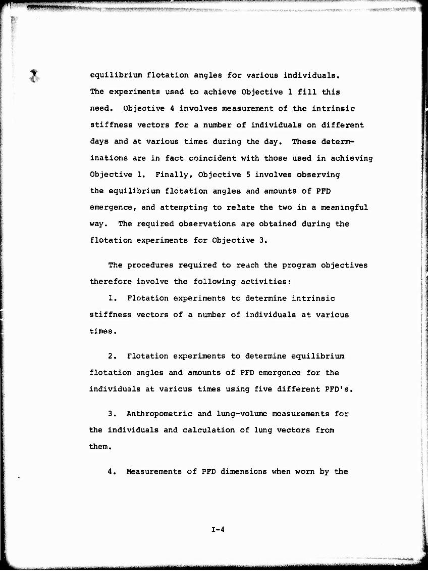
^Jt. equilibrium flotation angles for various individuals.
The experiments used to achieve Objective 1 fill this
need. Objective 4 involves measurement of the intrinsic
stiffness vectors for a number of individuals on different
days and at various times during the day. These determ-
inations are in fact coincident with those used in achieving
Objective 1. Finally, Objective 5 involves observing
the equilibrium flotation angles and amounts of PFD
emergence, and attempting to relate the two in a meaningful
way. The required observations are obtained during the
flotation experiments for Objective 3.
The procedures required to reach the program objectives
therefore involve the following activities:
1. Flotation experiments to determine intrinsic
stiffness vectors of a number of individuals at various
times.
2. Flotation experiments to determine equilibrium
flotation angles and amounts of PFD emergence for the
individuals at various times using five different PFD's.
3. Anthropometric and lung-volume measurements for
the individuals and calculation of lung vectors from
them.
4. Measurements of PFD dimensions when worn by the
1-4
i - ■ - - ..^^^---^---l-~~~~--—~~^-~--
imi'mmmmi^mmimtfi(wmwmi^m^^mmmmmwm .im i "■■■i m ^iwii1 iipP|fll^W,l'" »1VWW I i
,. -
V
individuals, and flotation experiments to determine buoy-
ant forces and centers of buoyancy associated with the
PFD's when worn by the individuals.
The methods and equipment described in Reference
1 for determining intrinsic stiffness vector and lung
vector were used. Devices and methods for performing
the other measurements were developed during the program.
1-5
- ■— -■■■ ■ ■ - —
mmmmmmmmmmm^^m^'^~~~~'■"'<"'. ■iiii.iiiin.iim.iiii , i^m m lt i—n» .„.^„„m.,.,--.. num...
II EXPERIMENTAL AND COMPUTATIONAL METHODS
A. Flotation Test Schedule And Subjects
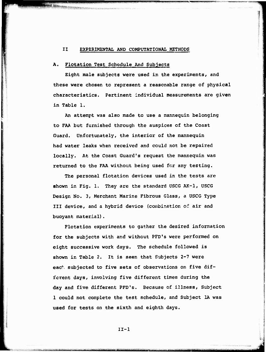
Eight male subjects were used in the experiments, and
these were chosen to represent a reasonable range of physical
characteristics. Pertinent individual measurements are given
in Table 1.
An attempt was also made to use a mannequin belonging
to FAA but furnished through the auspices of the Coast
Guard. Unfortunately, the interior of the mannequin
had water leaks when received and could not be repaired
locally. At the Coast Guard's request the mannequin was
returned to the FAA without being used for any testing.
The personal flotation devices used in the tests are
shown in Fig. 1. They are the standard USCG AK-1, USCG
Design No. 3, Merchant Marine Fibrous Glass, a USCG Type
III device, and a hybrid device (cornbination of air and
buoyant material) .
Flotation experiments to gather the desired information
for the subjects with and without PFD's were performed on
eight successive work days. The schedule followed is
shown in Table 2. It is seen that Subjects 2-7 were
ea^ subjected to five sets of observations on five dif-
ferent days, involving five different times during the
day and five different PFD's. Because of illness. Subject
1 could not complete the test schedule, and Subject 1A was
used for tests on the sixth and eighth days.
II-l
--■ - - 1—^^^^.^^^K^^^j^^m^mgjgMm

■ ■I i mmw 11 nin ■■Hill —■ " •- ■ ■——FW
^MMWMHMiftiini »mm- ■•■^•mmy'r
The test sequence for a given subject involved the
following steps:
1. Determination Of Lung Voluines Appropriate To
The Flotation Theory
As in Reference lf a spirometer was used to
first establish the functional residual capacity (FRC)
of the lungs as a reference, and then the change in lung
volume from FRC to the condition of the experiment.
Each experiment for measurement of intrinsic
stiffness vector was performed with the subject's lungs
inflated to produce zero net buoyancy, and the change
in lung volume from FRC to zero net buoyancy was deter-
mined. Each experiment to determine flotation angle of
a subject wearing a PFD was performed with the lungs in-
flated to an arbitrary comfortable condition, and the
change in lung volume from FRC to the arbitrary condition
was determined. The methods used were essentially those
described in Reference 1.
The lung volume changes and the individual's
measureiuents (Table 1} were used to compute the appropriate
lung vectors (LV) as defined in Appendix A.
2. Determination Of The Intrinsic Stiffness Vector
The intrinsic stiffness vector (ISV) was determined
by measuring the moments required to maintain the subject
at various equilibrium angles under conditions of neutral
II-2
■'>■'• «ut'mtmmiMmmtamt
,-...... ...—^ -.ii i ■iiiiiinn- : I* M

»mmm mmm*****?*^'*-*' ■'■•■■■ , ■. "■ ■:•.>",■■.«, !t,i.'.w-',^s.-^...v-"—.-^t*: VNHMM'VMMaMIMBMffMP ■■■' (WWB '
buoyancy. This was accomplished by fitting the test
subject with a harness, shown in Fig. 2, to which
weights and floats were attached so that the combina-
tion produced no net buoyancy. Variation of the
distance between the floats and weights provided the
necessary variation of the moment. The angleometer
described in Reference 1 was used to measure equilibrium
angle. From the definition of intrinsic stiffness vector
(Appendix A), it is seen that the relation between the
moment and angle will be sinusoidal for a rigid body.
Therefore a sine curve was fitted to the experimental
data and from it the magnitude WdT and phase angle 9T
of the ISV were found. This was done for both the head
back and head forward positions.
This sequence of measurements provided values of
the lung vector and intrinsic stiffness vector for each
flotation experiment involving one of the PFD's. In
addition, repetitive measurements were made of ISV and LV
in order to provide an indication of the inherent variability
of the measurements.
3. Determination Of Equilibrium Angle And PFD Emergence
With The Subject Wearing A Specific PFD
The subject donned the harness and the appropriate
PFD, entered the water, and was connected to the angleometer
II-3
■ ^ - -«— - '—.
witwirmmfmmr' ■ i ■■■■ mmmm* ■■ > K.i <iMifi.iwim«M»p«
I»«'
and spirometer. After the reference lung volume
corresponding to FRC was determined, the subject inhaled
to a comfortable level and stopped breathing for the
remainder of the experiment. The change in lung volume
from FRC to the experimental condition was determined
from the spirometer measurements. The remainder of the
experiment consisted of allowing the subject to reach
flotation equilibrium, recording the equilibrium angle,
and marking the water line on the partially emerged PFD.
This was done for both the head back and head forward
positions.
B. Determination Of The Effective Buoyancy And Center Of
Buoyancy Of PFD Worn By A Specific Subject
In order to use the flotation theory for prediction of
equilibrium flotation angle, it was necessary to determine
the buoyancy vector (BV) for the PFD being considered under
the exact condition of emergence observed in the flotation
experiment. The most direct way of determining center of
buoyancy of a submerged body having one plane of symmetry
is to determine the torques required to hold the body in
two different rotational positions beneath the water surface.
For the partially emerged PFD's, this technique is not
appropriate for two reasons. Firstly, the PFD cannot be
placed in more than one angular position while maintaining
II-4
- - " ■— ——M^»-" ■MMMMMI
'■pi. rmmm ■" JIWUM.CII
*.»-n'*:*,,','v-
i
the correct emerged portion; and secondly, changing the
rotational position of a PFD would cause It to shift Its
position and shape unless extraordlnay measures were taken
to fasten It to a rigid frame. For these reasons, an
approximate technique was used to determine center of
buoyancy from a single flotation experiment with the
PFD mounted on a wire torso irame.
Because of the unu«nial geometric configurations involved,
the computation technique associated with this method is
lengthy and difficult to display concisely, even though
only elementary geometry and trigonometry are used. For
this reason, only the overall concepts involved are ex-
plained here, while the details of the computation are
given in Appendix C along with a computer program listing.
Figure 3 is a representation of the arrangement used
to measure buoyancy and center of buoyancy of a partially
emerged device. For this purpose, the PFD is mounted on
a wire torso frame which conforms as closely as possible
to the torso of the human subject of interest. The weights
and centers of gravity of the torso frame and of the PFD
are determined beforehand by appropriate measurements in
air. These are denoted by CGp and CGß, respectively, in
the figure. In practice, some adjustment is needed to
account for the buoyancies of the emerged and submerged
II-5
-. ■'■■■■ ■- ■- - —■--'- -' - - .:■■..■■--■■ ^- ■ -
■ ■.■■..,,.■■,■—■...-.!,!,!„„-^^.^ -■■■■■■ mm ..^«M*^»*^^«^«^^
IM ■■■«■III ■!■
portions of the torso frame, but those details are omitted
here.
The torso frame and device are floated as shown in
Fig. 3 with weights Wi and W2 adjusted to produce the
desired waterline on the device. The effective buoyancy
BS of the PFD is then given by
BS - Wi + W2 + WT
where WT is the net weight of the frame in the partially
submerged position.
The location of the vertical line through CBs, the center
of buoyancy of the device in this position, is determined
from the summation of moments about point P, that is:
5:Mp = W^ + W2xw _ (BS)xs = 0
Xs = (WTXT + W2XW)/(BS)
Up to this point the determination is exact. An approxi-
mation is now introduced in order to determine a second
co-ordinate ys of the center of buoyancy. It is observed
first that the center of buoyancy of the fully submerged
device CBp is at or very close to its center of gravity
CGj). If any small difference between CGD and CBD is ignored,
it can be said that CBs can neither be above CGD nor below
II-6
h^i'-iiH^Va-^ ■■"— '-"- ^^—.<.^--..,*,,■-,.■, . 1 Mi .■■■11 ^_, iMMM
*mmmmmmm*mm\tm, m»^^ !*'('WWll*'w'" ^ffw^^T^^B
the lowest point of the PFD (point L in the example).
As an approximation, it is assumed that ys is propor-
tional to the effective buoyancy of the device BS
according to
Ts = BS
Yd BD
where BD is the effective buoyancy of the fully submerged
PFD. Co-ordinates xs and ys can be used to locate CBS
with respect to any desired reference point on the PFD.
That information along with measurements made of the
subject wearing the PFD allow determination of d^ and
6b in Figure IV-1 of Appendix A, and hence the buoyancy
vector for use in the flotation theory.
II-7
-■.w,*
- —'—i»^—^-— mmm «^MMMTI
WWWwwwffm'111 MW»I» it. I «Hwawtw'••. «tr ICMI««»«*«''« i->^»».vwm»w»lWfi"ll>W"»"i«w-«'i ̂^^^WWWBW^
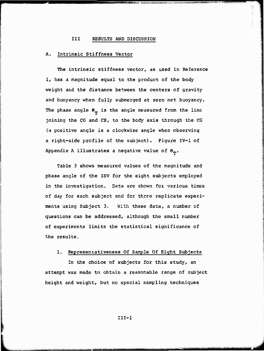
III RESULTS AND DISCUSSION
A. Intrinsic Stiffness Vector
The intrinsic stiffness vector, as used in Reference
1, has a magnitude equal to the product of the body
weight and the distance between the centers of gravity
and buoyancy when fully submerged at zero net buoyancy.
The phase angle 6 is the angle measured from the line
joining the CG and CBf to the body axis through the CG
(a positive angle is a clockwise angle when observing
a right-side profile of the subject). Figure IV-1 of
Appendix A illustrates a negative value of 9 .
Table 3 shows measured values of the magnitude and
phase angle of the ISV for the eight subjects employed
in the investigation. Data are shown for various times
of day for each subject and for three replicate experi-
ments using Subject 3o With these data, a number of
questions can be addressed, although the small number
of experiments limits the statistical significance of
the results.
1, Representativeness Of Sample Of Eight Subjects
In the choice of subjects for this study, an
attempt was made to obtain a reasonable range of subject
height and weight, but no special sampling techniques
III-l
. - ■ - -'■■ -■'-— ■- ■ —
(*:•,,
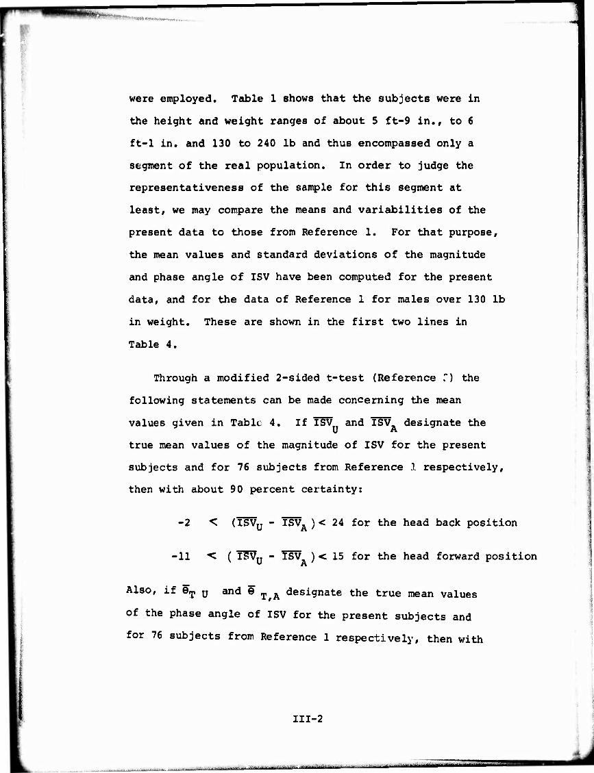
were employed. Table 1 shows that the subjects were In
the height and weight ranges of about 5 ft-9 in., to 6
ft-1 in. and 130 to 240 lb and thus encompassed only a
segment of the real population. In order to judge the
representativeness of the sample for this segment at
least, we may compare the means and variabilities of the
present data to those from Reference 1. For that purpose,
the mean values and standard deviations of the magnitude
and phase angle of ISV have been computed for the present
data, and for the data of Reference 1 for males over 130 lb
in weight. These are shown in the first two lines in
Table 4.
Through a modified 2-sided t-test (Reference ?) the
following statements can be made concerning the mean
values given in Table 4. If ISV and ISV designate the
true mean values of the magnitude of ISV for the present
subjects and for 76 subjects from Reference 1 respectively,
then with about 90 percent certainty:
-2 < (ISVu - I£>VA ) < 24 for the head back position
-11 < ( ISVy - T§V ) < 15 for the head forward position
Also, if eT u and 6 T^A designate the true mean values
of the phase angle of ISV for the present subjects and
for 76 subjects from Reference 1 respectively, then with
III-2
..- -JJt. „ —-.•..^.-...J,...-- ■ - - --.^ ■ -....-..-.-..., . r-mmi II [llllll—

about 90 percent certainty:
-6° "C (&r u" ^T A^ <-20 for the head back position
-2° < QT^'tT,!*)^9' for the head forward position
When the 90 percent confidence interval for the
difference between two mean values includes zero, as it
does in all four cases above, it is customary to state
that the true means for the samples involved are equal
at a level of significance of 10 percent. Since these
confidence intervals are rather sma.i 1 there is reason
for believing that the mean magnitudes and phases angles
for the present sample of eight subjects correspond
rather closely to those for the sample of 76 subjects
of Reference 1.
A completely satisfactory method for comparing the
variability of the present data with that from Reference
1 is not available because variabilities due to time of
day, as well as from person to person, are both involved.
Whereas the two variabilities can be estimated for the
present date, they cannot be for the Reference 1 data.
However, some appreciation can be obtained of the relative
variabilities by computing the standard deviation for
the present subjects at each specific time of day and
comparing these with the data for Reference 1 for all 76
subjects. In order to judge whether or not the present
III-3
..:;..-. ,..^„ >■ .^.-.-;.-. -v--.-^ ^ ■ ...^.^..-. ;-.,■:—uJ..^k..;-..-.■.„L......',.,,..^,,^—. ■,■■ , , ,■... ,..^..,.:.■. - -■——-■- -^.^.
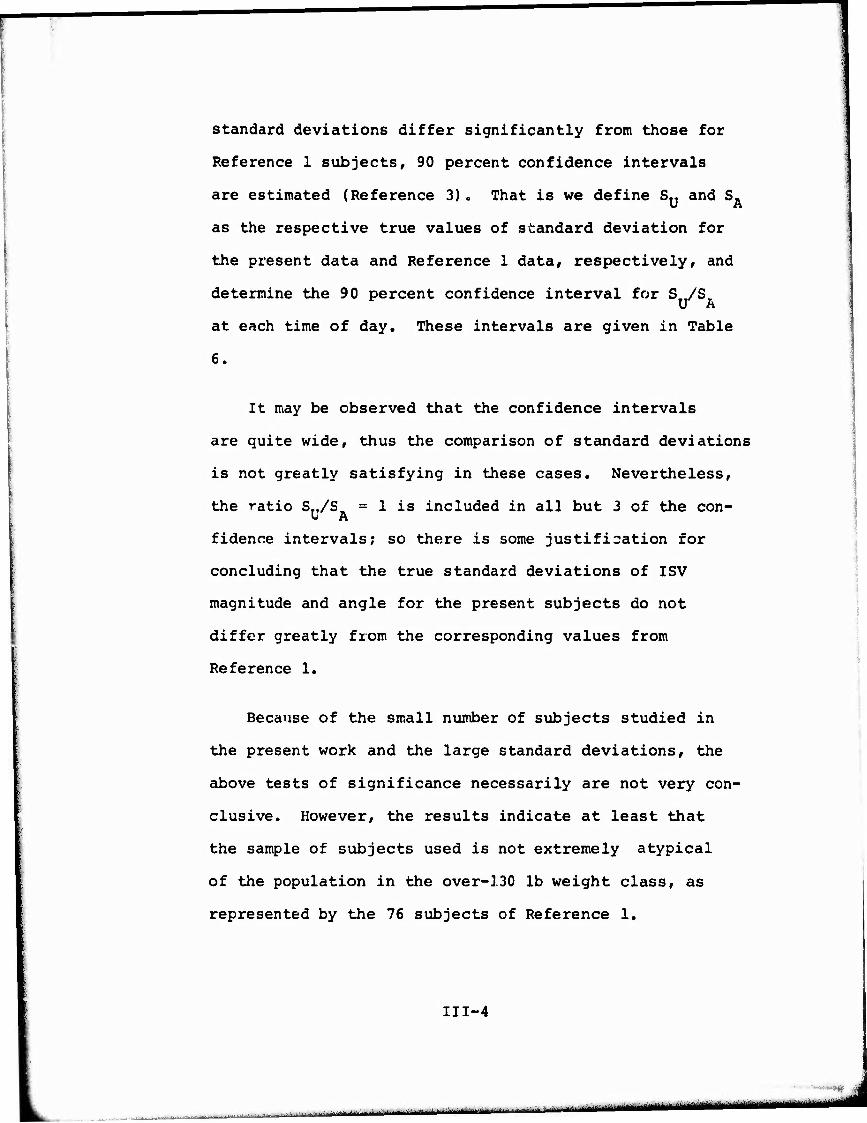
Standard deviations differ significantly from those for
Reference 1 subjects, 90 percent confidence intervals
are estimated (Reference 3)„ That is we define Sy and S.
as the respective true values of standard deviation for
the present data and Reference 1 data, respectively, and
determine the 90 percent confidence interval for S /S
at each time of day. These intervals are given in Table
6.
It may be observed that the confidence intervals
are quite wide, thus the comparison of standard deviations
is not greatly satisfying in these cases. Nevertheless,
the ratio S../S, = 1 is included in all but 3 of the con- U A
fidence intervals; so there is some justification for
concluding that the true standard deviations of ISV
magnitude and angle for the present subjects do not
differ greatly from the corresponding values from
Reference 1.
Because of the small number of subjects studied in
the present work and the large standard deviations, the
above tests of significance necessarily are not very con-
clusive. However, the results indicate at least that
the sample of subjects used is not extremely atypical
of the population in the over-130 lb weight class, as
represented by the 76 subjects of Reference 1.
111-4
-»..90
..i- -"-■— - '■■'—■■"■ ' • ' ""■i-
II i -- '""-" ■ •■"'*""*"'" "■■" -l.n.lim...r-llirilül
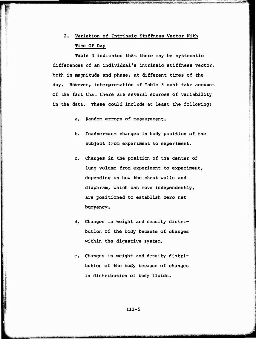
2. Variation of Intrinsic Stiffness Vector With
Time Of Day
Table 3 indicates that there may be systematic
differences of an individual's intrinsic stiffness vector,
both in magnitude and phase, at different times of the
day. However, interpretation of Table 3 must take account
of the fact that there are several sources of variability
in the data. These could include at least the following:
a. Random errors of measurement.
III-5
b. Inadvertant changes in body position of the
subject from experiment to experiment.
c. Changes in the position of the center of ■
lung volume from experiment to experiment,
depending on how the chest walls and
diaphram, which can move independently,
are positioned to establish zero net
buoyancy.
d. Changes in weight and density distri-
bution of the body because of changes
within the digestive system.
e. Changes in weight and density distri-
bution of the body because of changes
in distribution of body fluids.
unmmta^— - - ' ■MMHUIHMMIMI

■4 NtMWffWWW'JU&'V "■■
Items d and e are the day to day variations which
are sought, while Items a, b, and c are the inherent
variabilities of the experiment. In order to estimate
the latter, the data on 3 replicate tests with Subject
3 may be used, although some limitations in the accuracy
of the estimate are evident. Firstly, it is probable
that the variabilities introduced by Items b and c
would be less for a series of consecutive experiments
on a single day than for replicate experiments conducted
on different days. This statement is based on the
observation that a subject would be less and less able
to exactly reproduce body position and lung volume with
the passage of time. Secondly, since only 3 replicate
experiments were possible, the statistical significance
of any conclusions cannot be great.
From the replicate tests on Subject 3 (see Table 3),
the estimates of standard deviation shown in Table 7 have
been made.
Because data from only 3 replicate experiments are
available, these cannot be regarded as highly reliable
estimates of the true standard deviation. Specifically,
it may be observed that the 95 percent confidence
intervals for the standard deviations shown in Table 7
are as shown in Table 8 (Reference 4).
III-6
— •— - ■-..,....-.■——^
mum ^^.^^^^^^^.^^^^^MM^a^M,,,...,.^
niiiuiiiiam ■iiiii"»i ■ ■»■ r ■ nii"i i ! 11 i "■"" ""7 '■■ —-•---
WHtHKtKitSiktmmmmmmmßmmmm^mmmmmmmmmimmmmmmmmmmmmmmmmmmmm(Mm ■
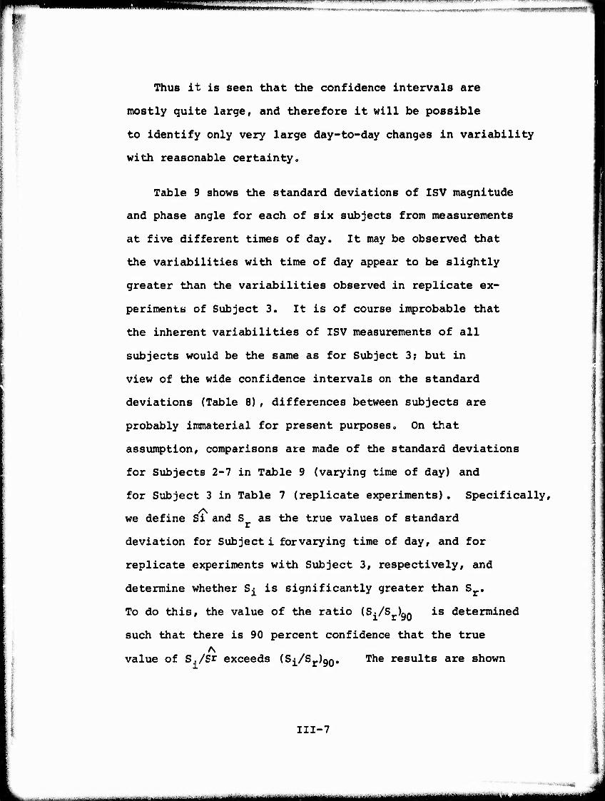
Thus it is seen that the confidence Intervals are
mostly quite large, and therefore it will be possible
to identify only very large day-to-day changes in variability
with reasonable certainty.
Table 9 shows the standard deviations of ISV magnitude
and phase angle for each of six subjects from measurements
at five different times of day. It may be observed that
the variabilities with time of day appear to be slightly
greater than the variabilities observed in replicate ex-
periments of Subject 3. It is of course improbable that
the inherent variabilities of ISV measurements of all
subjects would be the same as for Subject 3; but in
view of the wide confidence intervals on the standard
deviations (Table 8) , differences between subjects are
probably immaterial for present purposes. On that
assumption, comparisons are made of the standard deviations
for Subjects 2-7 in Table 9 (varying time of day) and
for Subject 3 in Table 7 (replicate experiments). Specifically,
we define Si and S as the true values of standard
deviation for Subject i forvarying time of day, and for
replicate experiments with Subject 3, respectively, and
determine whether S^ is significantly greater than Sr.
To do this, the value of the ratio (SJ/S^QO is determined
such that there is 90 percent confidence that the true
value of S./Sr exceeds (Sj/Sr)gQ, The results are shown
III-7
. ......I-^I^.J;J,-L.,..^,.->,.^-.^^,.-■ .■—■■...-in | „n ami <II - -- —- ^ -^
————————
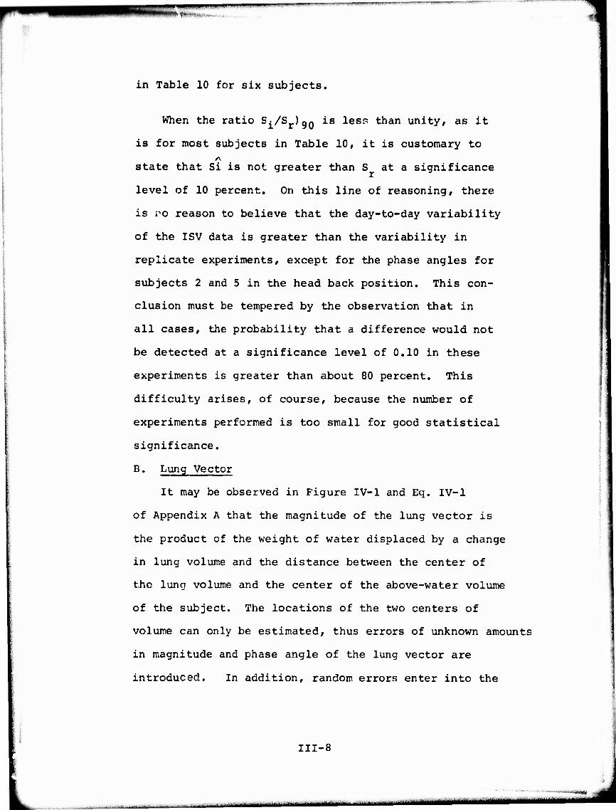
in Table 10 for six subjects.
When the ratio S^/Sr)gQ is lesp than unity, as it
is for most subjects in Table 10, it is customary to
state that Si is not greater than S at a significance
level of 10 percent. On this line of reasoning, there
is vo reason to believe that the day-to-day variability
of the ISV data is greater than the variability in
replicate experiments, except for the phase angles for
subjects 2 and 5 in the head back position. This con-
clusion must be tempered by the observation that in
all cases, the probability that a difference would not
be detected at a significance level of 0.10 in these
experiments is greater than about 80 percent. This
difficulty arises, of course, because the number of
experiments performed is too small for good statistical
significance.
B. Lung Vector
It may be observed in Figure IV-1 and Eq. IV-1
of Appendix A that the magnitude of the lung vector is
the product of the weight of water displaced by a change
in lung volume and the distance between the center of
the lung volume and the center of the above-water volume
of the subject. The locations of the two centers of
volume can only be estimated, thus errors of unknown amounts
in magnitude and phase angle of the lung vector are
introduced. In addition, random errors enter into the
III-8
; — ■ ■ - ■—■' ^^^....i». '^.^^m^^tfutmmä
wmmmmm*^^^*—**!^^^^
'.
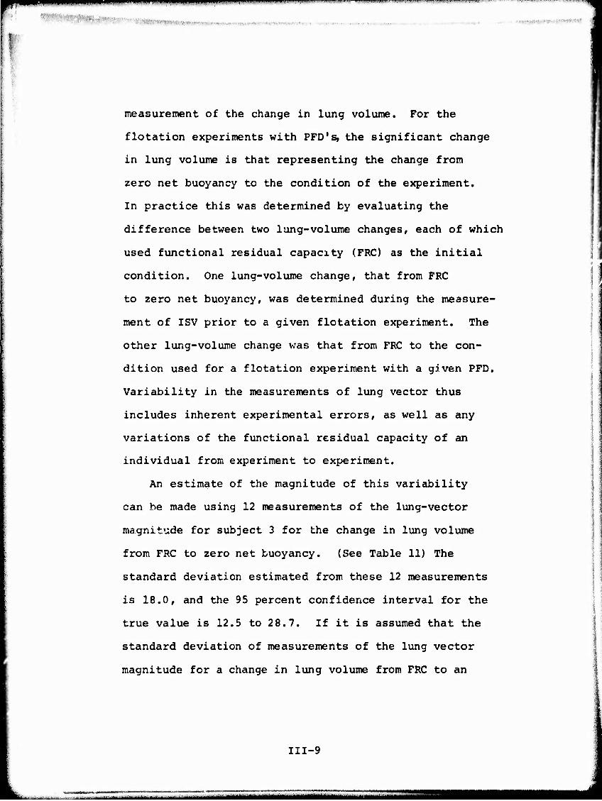
measurement of the change in lung volume. For the
flotation experiments with PFD's, the significant change
in lung volume is that representing the change from
zero net buoyancy to the condition of the experiment.
In practice this was determined by evaluating the
difference between two lung-volume changes, each of which
used functional residual capacity (FRC) as the initial
condition. One lung-volume change, that from FRC
to zero net buoyancy, was determined during the measure-
ment of ISV prior to a given flotation experiment. The
other lung-volume change was that from FRC to the con-
dition used for a flotation experiment with a given PFD.
Variability in the measurements of lung vector thus
includes inherent experimental errors, as well as any
variations of the functional residual capacity of an
individual from experiment to experiment.
An estimate of the magnitude of this variability
can be made using 12 measurements of the lung-vector
magnitude for subject 3 for the change in lung volume
from FRC to zero net buoyancy. (See Table 11) The
standard deviation estimated from these 12 measurements
is 18.0, and the 95 percent confidence interval for the
true value is 12.5 to 2 8.7. If it is assumed that the
standard deviation of measurements of the lung vector
magnitude for a change in lung volume from FRC to an
III-9
——~——~—~-——~~~~—~*-*

•^i
f
experimental condition with a PFD has the same standard
deviation, then it may be estimated that the standard
deviation of the lung-vector magnitude associated with
a change in volume from zero net buoyancy to the condition
of an experiment with a PFD is 25.4, and has a 95 percent
confidence interval of 17.8 to 40.5. This is tantamount to
neglecting errors that may be associated with the determina-
tion of the exact point of zero net buoyancy. Thus, the
latter standard deviation tends to be overestimated some-
what. It will be shown in a later section that variations
of lung vector magnitude by the amount of this standard
deviation would have very large effects on the predicted
equilibrium flotation angle of a subject PFD combination.
C. Equilibrium Flotation Angle Of Subjects With Various PFD's,
1. Comparison Of Observed And Calculated Equilibrum
Angles.
During the flotation experiments with the various
PFD's, the equilibrium flotation angles were directly
measured. In addition, sufficient information was obtained
to determine the magnitudes and phase angles of the
intrinsic stiffness vector, the lung vector, and buoyancy
vector of the PFD corresponding to each experiment. It
was possible therefore, to determine the equilibrium angle
predicted by the theory of Reference 1 for each flotation
experiment.
A summary of the observed and calculated results is
111-10
^■„■^l,^^M^^.,1.,),r-lit.f,^W.M»„»1, .t.^i.*., .fhi^ „ ■■M.n ■■ T i,.,! IM|i,i . >;■■„ ' itttämj^ääa^i^^^a^^m^t^tm^imum^l^m^tti^^^m^
■ . . . '
. ■
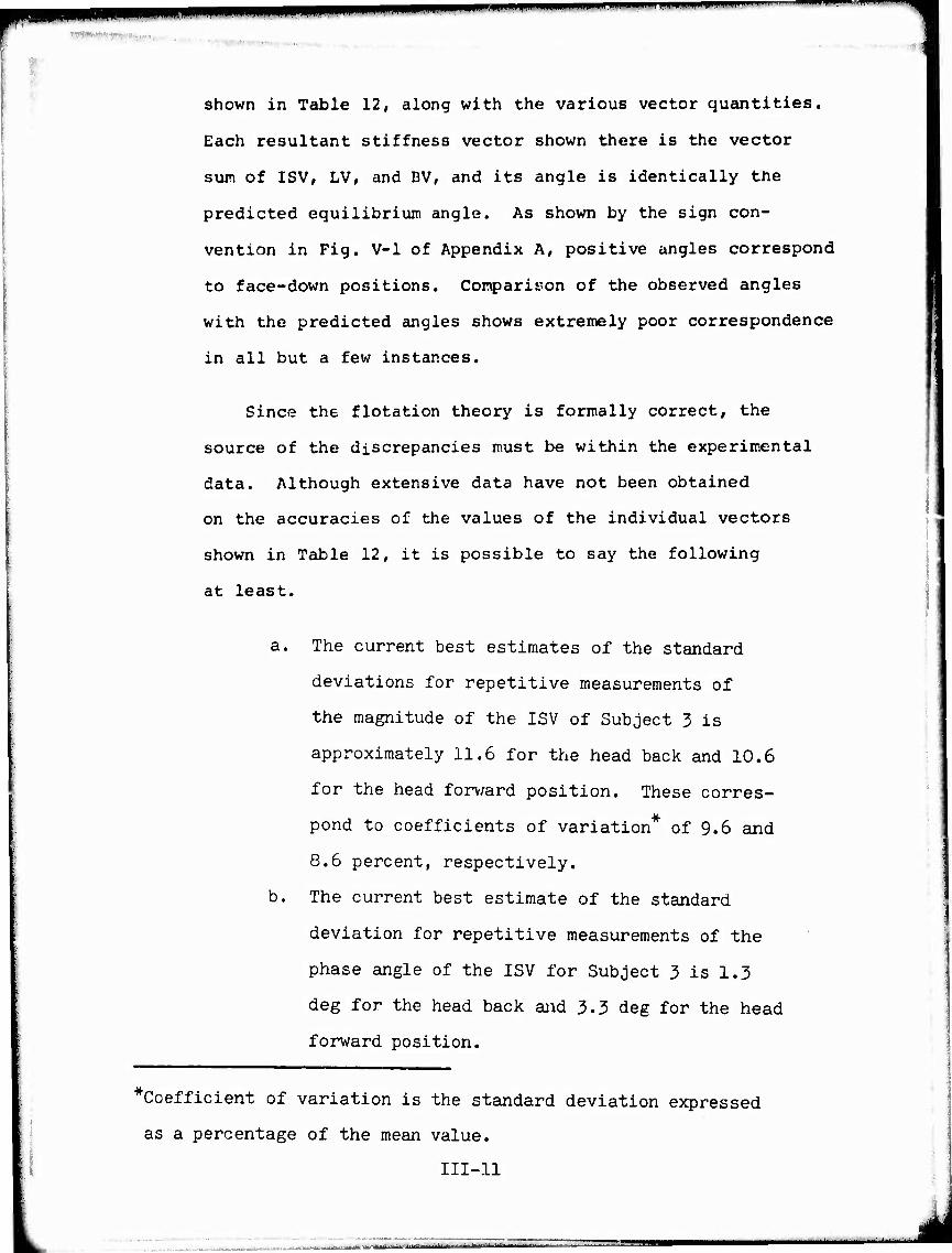
shown in Table 12, along with the various vector quantities.
Each resultant stiffness vector shown there is the vector
sum of ISV, LV, and BV, and its angle is identically the
predicted equilibrium angle. As shown by the sign con-
vention in Fig. V-l of Appendix A, positive angles correspond
to face-down positions. Comparison of the observed angles
with the predicted angles shows extremely poor correspondence
in all but a few instances.
Since the flotation theory is formally correct, the
source of the discrepancies must be within the experimental
data. Although extensive data have not been obtained
on the accuracies of the values of the individual vectors
shown in Table 12, it is possible to say the following
at least.
a. The current best estimates of the standard
deviations for repetitive measurements of
the magnitude of the ISV of Subject 3 is
approximately 11.6 for the head back and 10,6
for the head forv/ard position. These corres-
pond to coefficients of variation* of 9.6 and
8.6 percent, respectively.
b. The current best estimate of the standard
deviation for repetitive measurements of the
phase angle of the ISV for Subject 3 is 1.3
deg for the head back and 3.3 deg for the head
forward position.
* Coefficient of variation is the standard deviation expressed
as a percentage of the mean value.
III-ll
j^ttmnMY- -.-'■---■ ■ . .,__.-. -^■—.. ■■ ■■": '' m^ma^mi^m^m^^^^^^^^^^^—^^****'*******''*'"*-"-*

99mm •" • •
c. The current best estimate of the
standard deviation for repetitive
measurements of the magnitude of
the lung vector for Subject 3 is
25.4 in both head positions. This
corresponds to a coefficient of
variation of 40 percent.
d. Systematic errors of unknown amount
are included in both magnitude and
phase angle of the lung vectors
because the true centers of the
lung volumes and the above-water
volumes for the subjects are not
known.
e. The buoyancy vector is determined by
an approximate procedure which introduces
uncertainty in the location of the
center of buoyancy of the PFD. This,
along with uncertainty in the location
of the center of the above-water volume,
introduces errors of unknown amount in
both the magnitude and phase angle of
BV.
111-12
■■ — ■ -— n n n -nr '—I—> MUtmamm ■■• -^ " MiiiilMiilMiliMlMHMI ■■■■■'>'**'*ueiMlfl

■■mini.— ..— . ... mm ■■■—■■■■
im iiiwunH.HPpp.. i — —' "- IIIIWIIIUIW.W"W.P"'
f. The nature of the experiments suggest
that the observed equilibrium angle
is reliable within a few degrees and is
probably the least source of error in
the comparison with predicted angles.
The following section addresses possible implications
of these factors.
2. Sensitivity Analysis Of Flotation Theory
In view of the small number of experiments which
were possible, the statistical information obtained is
scanty, and thus a complete analysis of the propagation
of errors is not feasible. Nevertheless, an analysis
of the sensitivity of the calculated equilibrium angle
to small changes in the input data is possible. Such an
analysis can serve two purposes. It can identify para-
meters to which the prediction is highly sensitive, and
thus suggest likely sources of the large discrepancies
shown in Table 12. And it can also show the accuracy
required in the measurement of the input data for any
desired accuracy of the predicted result.
The details of the sensitivity analysis are given in
Appendix D. There, the results of the analysis are
applied to three subjects from Reference 1 in order to
show the consequences of errors in measured quantities.
It is perhaps more informative to apply the analysis to
111-13
- ■■■- - ■■ - — ■ -- -,—■-,^— iMMMMMMablM. mmmm ■^^MMMOMMf
■•'■-«tK**Vi.)^„«irf> ti^
WW""""» ■ IM. iiumiiiin .■i.i' 1.111 ii—II~.... imm MM1"I " muumm
■ ' i ■ ■ ■ HW' ' ' "■■■:Vl
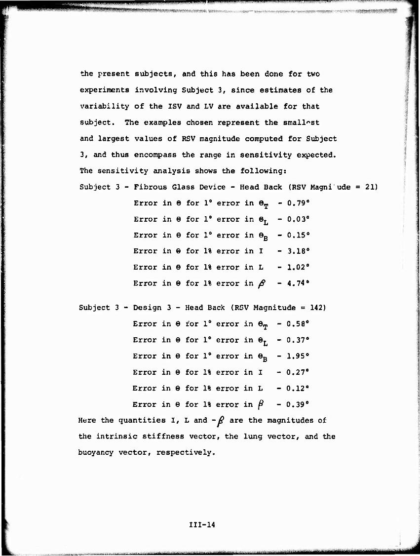
the present subjects, and this has been done for two
experiments involving Subject 3, since estimates of the
variability of the ISV and LV are available for that
subject. The examples chosen represent the smallest
and largest values of RSV magnitude computed for Subject
3, and thus encompass the range in sensitivity expected.
The sensitivity analysis shows the following:
Subject 3 - Fibrous Glass Device - Head Back (RSV Magni ude = 21)
Error in 6 for 1° error in eT - 0.79°
Error in 6 for 1° error in eL - 0.0 3°
Error in 6 for 1° error in eB - 0.15°
Error in 9 for 1% error in I - 3.18°
Error in 6 for 1% error in L - 1.02°
Error in 6 for 1% error in ^ - 4.74°
Subject 3 - Design 3 - Head Back (RSV Magnitude = 142)
Error in 6 for 1° error in eT - 0,58°
Error in 6 for 1° error in eL - 0.37°
Error in 6 for 1° error in eB - 1.95°
Error in 6 for 1% error in I - 0.27°
Error in 6 for 1% error in L - 0.12°
Error in 6 for 1% error in ^ - 0.39°
Here the quantities I, L and -y? are the magnitudes of
the intrinsic stiffness vector, the lung vector, and the
buoyancy vector, respectively.
111-14
__ . . i m in ■ i ■ ■- — -- ■- ■•— ....^■^■i~~****iiait*i**iiii**tuimmtt
■PHHMMWaHPiPaiiWMaBKPnHMWmip i i ii. in an ii. i in nai wm ' ' ' ■"'
From these values, the potential errors corresponding
to estimated standard deviations of measured quantities
may be evaluated as shown in Table 13.
There is no information at present on the possible
errors of measurement of the magnitude and angle of the
buoyancy vector or the angle of the lung vector. It is
reasonable to suppose, however, that errors of 10 percent
in the magnitude and 5° in the angles could easily occur.
These are used in the example shown in Table 14.
As pointed out in Appendix A, the sensitivity
analysis is numerically correct only for very small in-
crements in the variables. Thus, the large increments
in some variables in Tables 13 and 14 must be regarded
only as indicative of potential sources of large error.
The tables show that the largest sensitivity
to errors occurs for the fibrous glass device where the
calculated magnitude of the resultant stiffness vector
(RSV) is 21. For that device, random errors in ISV and
LV along with a small error in BV could well be responsible
for the large difference (70°) between calculated and
observed equilibrium angles. Analysis of other situations
wherein the magnitude of RSV is small would undoubtedly
lead to the same conclusion.
For the Design 3 device. Tables 13 and 14 indicate that
random errors in ISV and LV magnitudes are unlikely to
111-15

*i!ilW'<W|l«w»'"wi»»(- ■ ^M '^mm^mmmm ■pnwi..
't.^-''*:, ■ r.
cause large errors in 6. For example, if ISV and LV
magnitudes were in error by two standard deviations
simultaneously to produce additive errors, the error in
e would be only about 15°. Yet the probability that
either error would be two standard deviations or more
is less than 0.05 (for normally distributed errors) and
the probability that both would have that magnitude
simultaneously is probably considerably less than .01.
Furthermore, the tables show that very large errors in
magnitude and angle of BV or the angle of LV would be
required to produce the observed error in predicted
equilibrium angles (110° in this case) . Analysis of other
situations wherein the magnitude of RSV is large would
undoubtedly lead to a similar conclusion.
Examination of Table 12 shows that there is no
apparent correlation between the magnitude of RSV and
the discrepancy between observed and calculated equil-
ibrium angles. This strongly suggests that random
errors in ISV and LV are not entirely responsible and
that large unidentified errors are present in some of
the data. It is pointed out that the true magnitude of
RSV is not known for any of the experiments. Since the
predicted angle of RSV is not reliable, the predicted
magnitude must be viewed with suspicion as well.
111-16
.—^—„^—- ii m

111-17
Although the limited scope of this study does not
permit further investigation to identify the errors, it
appears that the most likely sources are the approxima-
tions used in locating the center of lung volume, center
of above-water volume of the subject, and the center of
buoyancy of the PFD. The potential for error is pro-
bably greatest in the latter, since the buoyancy vector
will usually have a larger effect on equilibrium angle
than the lung vector. This thesis is supported by the
observation that large values of buoyancy vector magnitude
seem to be associated with large errors in predicted
angle in Table 12.
The determination of the buoyancy vector for a given
device is an inherently inexact procedure because of the
practical difficulties associated with available experi-
mental techniques. The determination involves first a
flotation experiment with a subject, and second a flota-
tion experiment with the PFD mounted en a wire frame which
is supposed to duplicate the shape of the subject's torso.
A reference point on the PFD must be accurately located
with respect to reference points on the subject and on the frame.
In the flotation experiment with the frame, the
emerged portion of the PFD must duplicate that which
occurred with the subject, and the buoyi.:.t force developed
must be measured. In addition, the points of application
» 1 „. ,.<,■■,-.-■»■,. ■|,„,i „■„.„,,„.,„„. . — ' - ■ l .mLJ„^^^.^^Mi^^^^Mj^MMi^Mi^MaK...^
•" "■■"' ■—"■ " "■" '' "»—n
.■
of downward forces on the wire frame must be located
with respect to the chosen reference point on the PFD.
From the measurements with the PFD on the wire frame,
the location of the center of buoyancy of the PFD
relative to the reference point is then estimated by
the approximate procedure described previously. Finally,
the location of the center of buoyancy of the PFD relative
to the center of the above-water volume of the subject
is calculated from the above information and from physical
measurements of the subject.
It is evident that there are numerous sources of
error in the above procedures. These arise mainly be-
cause of the practical difficulties involved with measur-
ing distances between the various parts of the subject
and the PFD, both of which are non-rigid bodies, and
of duplicating with the wire frame the exact position
of the PFD as worn by the subject. Errors are also
introduced by the approximations used in locating the
center of the above-water volume of the subject and the
center of buoyancy of the PFD. The comparisons of observed
and predicted equilibrium angles and the sensitivity
analysis suggest that the accumulation of errors involved
in these procedures can be so large that no confidence
can be placed in predicted angles.
111-18
u^^t^ .-^^^ ^^M
PPM rn—Twrr--'"»---"' -™**y*i' ' nm
:■■
As a side issue, it may be observed that the
magnitude of RSV is identically equal toQU/de at equil-
ibrium. Thus it is indicative of the stability of the
equilibrium position (M is net turning moment on the
subject) . It is clear therefore that a small change in
any turning moment could have a large effect on the
equilibrium angle whenever RSV has a small magnitude.
Although the foregoing analysis involves sensitivity
of a theory to changes in variables, the sensitivities
estimated apply to the physical behavior of a subject -
PFD system as well. Thus, a condition which leads to
highly stable flotation of a subject is one in which
the magnitude of RSV is large. This raises the question
as to the possible use of RSV magnitude in the evaluation
of the effectiveness of e. PFD.
D. Comparative Effectiveness of PFD's.
A number of factors would contribute to the ability
of a device to hold a subject in a face-up position (negative
equilibrium angle) and resist forward turning. Among
these are; large buoyant force, CB located far from the
head, and CB located far in front of the body axis. In
the terminology of the flotation theory, the desired
properties are a buoyancy vector with large magnitude
and positive phase angle. In addition, it is desirable to
have a resultant stiffness vector with large magnitude
111-19
WP"
in order to assure stability of the equilibrium position.
In principle then, it should be possible to compare the
various PFD's on the basis of buoyancy vector and resultant
stiffness vector. However, for the present study, the
computed angle of RSV has been shown to be unreliable
for estimating equilibrium flotation angle, and thus the
computed magnitude of RSV must be considered questionable
as well.
Table 15 shows the observed equilibrium flotation
angles and Table 16 shows the buoyancy vectors determined
for the various PFD - Subject combinations. Comparisons
between buoyancy vectors and flotation angles shows a
number of apparent inconsistencies, where negative
angles of the buoyancy vector occur with negative flotation
angles (2F with Fibrous Glass, 3F with Design 3 and
Fibrous Glass, 6F with AK-1); or where positive angles
of the buoyancy vector occur with positive flotation
angles (2F with Type III, 3F with Type III). This further
suggests that the buoyancy vectors determined by the
approximate procedure described previously are not accurate
enough to be useful in predicting flotation angle of a
subject.
The observed equilibrium flotation angles are useful
for judging the relative effectiveness of the various
111-20
■ - -- ■ .'"^—^•■•i"'"
f^m*^^^***^m^m^mTm »m ■>» i num ijuiijuni.,,. i ■n..,, m.i.p.i i,., in K,,!,!,!.!.,!!-,,.^.—,....,, „ iii..,,.,...,.,!,!,,,.,,.!!^,,,,,,,,,,.,,,,^
PFD's (Table 15), Since a negative angle corresponds
to the face-up position, this is the desirable condition.
It is seen that the Design 3, Fibrous Glass, and Hybrid
devices floated all subjects face up at least 20° back
from vertical; and the AK-1 did the same except for Sub-
ject 1 in the head forward position. In that case
however, the Subject was floated high enough that the
slight forward angle was acceptable. On the basis of
this limited data, it can be said that these four devices
appear to be similar in effectiveness, with a slight
reservation with respect to the AK-1. The Type III
device, on the other hand, was able to float only 1 of
the 6 subjects at a negative (face up) angle in the
head-forward position, and then at only -1°. This
appears to be a lower level of performance than that
shown by the other devices.
Consideration of the physical characteristics of the
devices (see Fig. 1) shows why the devices behave as they
do. Devices which have centers of buoyancy far from the
head, will also tend to produce large buoyant forces be-
cause the subjects are raised far out of the water. Both
factors lead to a large magnitude of BV. Design 3 has
these characteristics and in addition its center of buoy-
ancy is well in front of the body axis. It is not surprising
then that it is one of the most effective devices. The
111-21

MPW " "" l'WW"- ' ■•"-■•»pw.—i«i-,-inni-^-«-i. WT-^.I.« rimiiR^jiii IIM i J i «i i wii«»
•W"»,-»., .
' ' ■iWlfWM
AK-1, Fibrous Glass, and Hybrid Devices would apparently
not raise the subjects as high above the water as would
the Design 3 device, and thus would produce somewhat
lesser buoyant forces. Nevertheless, all have centers
of buoyancy well below the head and in front of the chest,
and thus would be expected to perform well. The Type III
device, however, appears to have its center of buoyancy
near the body axis. For this reason, it is capable
itself of producing a forward turning moment for the
head forward position, and cannot rotate a subject out
of a face-down position, even though it may have a large
buoyant force and a center of buoyancy well below the
head.
E. Effect Of PFD Emergence On Equilibrium Flotation Angle.
The effect of PFD emergence on the flotation angle
of a subject involves its effect on both the buoyant force
B and the location of the center of buoyancy CB. The
relationship of the buoyant force to the emergence is
direct, whereas the relationship of the location of center
of buoyancy to emergence is quite complex. As described
previously, an approximate method was used to estimate
the location of CB for partially emerged devices. Even so,
rather involved computations were necessary, so it would
be desirable to have a simpler approach. For the present,
this seems to be infeasible since the approximate method
111-22
—,— -■ - ■ ■ - mm,imaammtmmm^imtttimmimmammmmu~l.a
T^w^^w^ü^ -- " *'■■'■!"
«';w.,iHiJiii)H)IWWI"'HIMII>
used here does not itself appear to be sufficiently
accurate for predicting CB, and a simplified procedure
is not likely to offer any improvement. The following
discussion illustrates the complexity of the situation.
Depicted schematically in Fig. 4 is a partially
emerged PFD positioned in a manner typical of a head-back
equilibrium. In assessing the effect of emergence on
the equilibrium angle, we observe the following. The
turning moment caused by the PFD is the horizontal
component of the buoyancy vector which is numerically
equal to -Bd_ sin (e-eD) . (In the sign convention used,
a positive moment tends to produce rotation through a
negative angle, that is, counterclockwise in Fig. 4).
A change in the amount of emerged material tends to
change all of the quantities B, dB, and eB, which could
produce opposing effects on the turning moment. For
example, if the emergence is increased with Ö held con-
stant, the buoyant force B decreases tending to reduce
the moment. On the other hand, as the emergence increases,
the point CB moves farther away from CBD along the
line through CBE and CBD, and CTfcmoves closer to the
water line. Note that this corresponds to movement of
the PFD upward relative to the subject. With a given
subject, this must occur because the above-water volume
of the subject must decrease as the buoyant force decreases,
111-23
^■l l..--L...i,.,^m^.>l-, ,■■., ,,, ■■■■ - -■■ --- m M j | ^ 'i —-

wwmmim&wwm*'
"^-■n-^-w-. . .. I-. ****-
WH*'-**? I
Depending upon the configuration of the system, these
movements of CB and CVocould increase or decrease d and
e_. and thus could tend to increase or decrease the turning
moment. Movement of CV0would also affect the lung vector
to some degree.
For certain PFD's, the largest effect would be produced
by the change in B, and increasing emergence would result
in decreasing buoyancy vector. The result would be for-
ward turning of the subject until the balance between
net stiffness vector and buoyancy vector were re-established
at an anglo © nearer to the vertical. This situation
appears to apply to devices with emerged material in
front of the subject's chest, such as the Design 3 and
Type III Devices. For PFD's with significant amount of
buoyant material behind the head, such as the AK-1 and
Hybrid Devices, the predominant effect would probably
be the increase in d- with increasing emergence, resulting
in increasing buoyancy vector and rearward turning of
the subject.
Generalization of the above reasoning to comparisons of
different subjects is obviously much more complicated
since the differences in net stiffness vector and location
of the center of the above-water volume will have large
effects. For this reason, the use of the present data
to show the effect of PFD emergence is rather inconclusive.
«■■
111-24
•••'• - ■ i—-- -' ■
„■-"»^■«.■ni.HI ^ ' 1 -^->—^-- -
- ■■«WfMVHWIWft"! ' ■
Table 17 shows the emergence of the various PFD's
(in percent of total buoyancy utilized) along with the
equilibrium angles for the eight subjects. Only for
the Fibrous Glass Device does a trend appear to be present.
For that device, the equilibrium position seems to move
away from the vertical as emergence of the PFD increases.
This would place the Fibrous Glass device in the category
for which loss in buoyancy behind the head results in
an increasing rearward turning moment. The configuration
of the device is compatible with this characteristic,
but the variability among subjects may well be responsible
for the trend shown. For the other devices used, it
appears that variations among individual subjects mask
any relationship that might exist between emergence and
equilibrium angle.
111-25
.......^.»-'-" ■.-~^.-.. .-■■...■..., rm r,m„r,.MimM*mm*>~.~*-~^
Jill l.iy.1^11 I Ml ,^^nmm^. , „„MI ■..,„ ,,,. I ,,.,p,|.—i„,,,w ^..i.nin.l.l.HWi > <■ ■ l.-WT"I- —ir^-
■
■ ■■
IV CONCLUSIONS
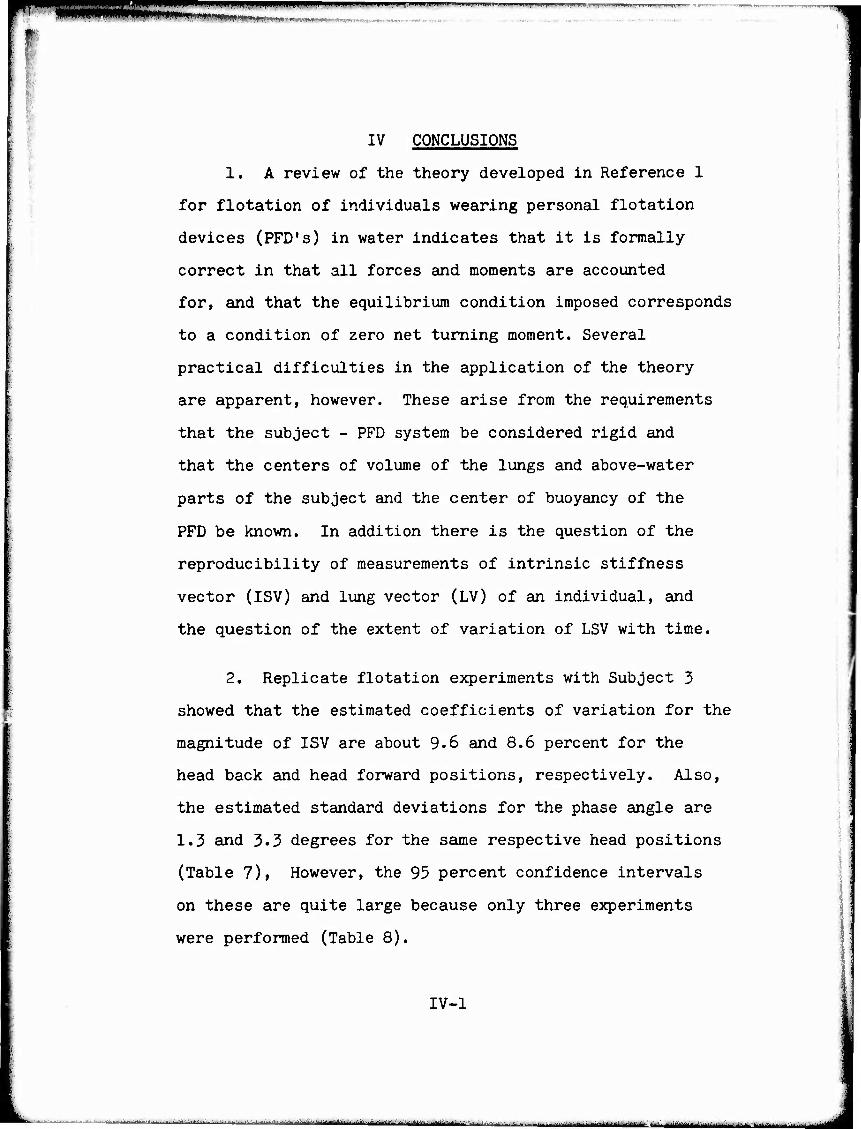
1. A review of the theory developed in Reference 1
for flotation of individuals wearing personal flotation
devices (PFD's) in water indicates that it is formally
correct in that all forces and moments are accounted
for, and that the equilibrium condition imposed corresponds
to a condition of zero net turning moment. Several
practical difficulties in the application of the theory
are apparent, however. These arise from the requirements
that the subject - PFD system be considered rigid and
that the centers of volume of the lungs and above-water
parts of the subject and the center of buoyancy of the
PFD be known. In addition there is the question of the
reproducibility of measurements of intrinsic stiffness
vector (ISV) and lung vector (LV) of an individual, and
the question of the extent of variation of LSV with time. ■
2. Replicate flotation experiments with Subject 3
showed that the estimated coefficients of variation for the
magnitude of ISV are about 9.6 and 8.6 percent for the
head back and head forward positions, respectively. Also,
the estimated standard deviations for the phase angle are
1.3 and 3.3 degrees for the same respective head positions
(Table 7)» However, the 95 percent confidence intervals
on these are quite large because only three experiments
were performed (Table 8).
IV-1
- ■i«W.1.'ar«lM.VJliflWI«.«.i.l.....'..... .■.,.Jl...,...l.;a.,AH.,l,„.,. i ....r ,i ..i ■■-■nm., .u: ^.J.„,:, ,.»^ .w,—, ■ ... . , ..L.,.-,.^ , .... ^ ......
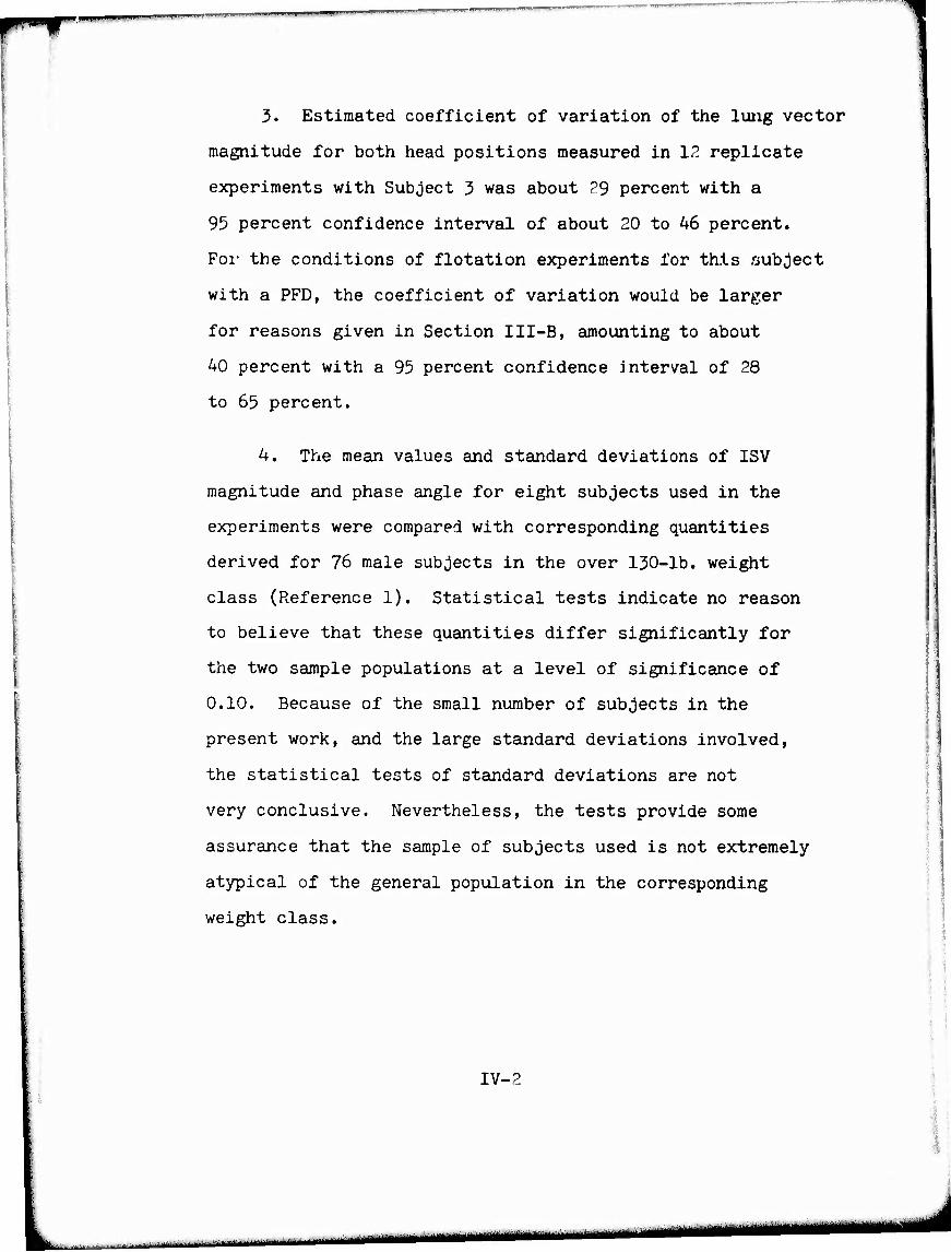
3. Estimated coefficient of variation of the lung vector
magnitude for both head positions measured in 12 replicate
experiments with Subject 3 was about 29 percent with a
95 percent confidence interval of about 20 to 46 percent.
For the conditions of flotation experiments for this subject
with a PFD, the coefficient of variation would be larger
for reasons given in Section III-B, amounting to about
40 percent with a 95 percent confidence interval of 28
to 65 percent.
4. The mean values and standard deviations of ISV
magnitude and phase angle for eight subjects used in the
experiments were compared with corresponding quantities
derived for 76 male subjects in the over 130-lb. weight
class (Reference 1). Statistical tests indicate no reason
to believe that these quantities differ significantly for
the two sample populations at a level of significance of
0.10. Because of the small number of subjects in the
present work, and the large standard deviations involved,
the statistical tests of standard deviations are not
very conclusive. Nevertheless, the tests provide some
assurance that the sample of subjects used is not extremely
atypical of the general population in the corresponding
weight class.
IV-2
r- -■'-■■■■ - | ■ -.■■■»-:— --^-^—"—»«^
WWW——i
ii|i>,HM»'ll ' ' ' ' "ll
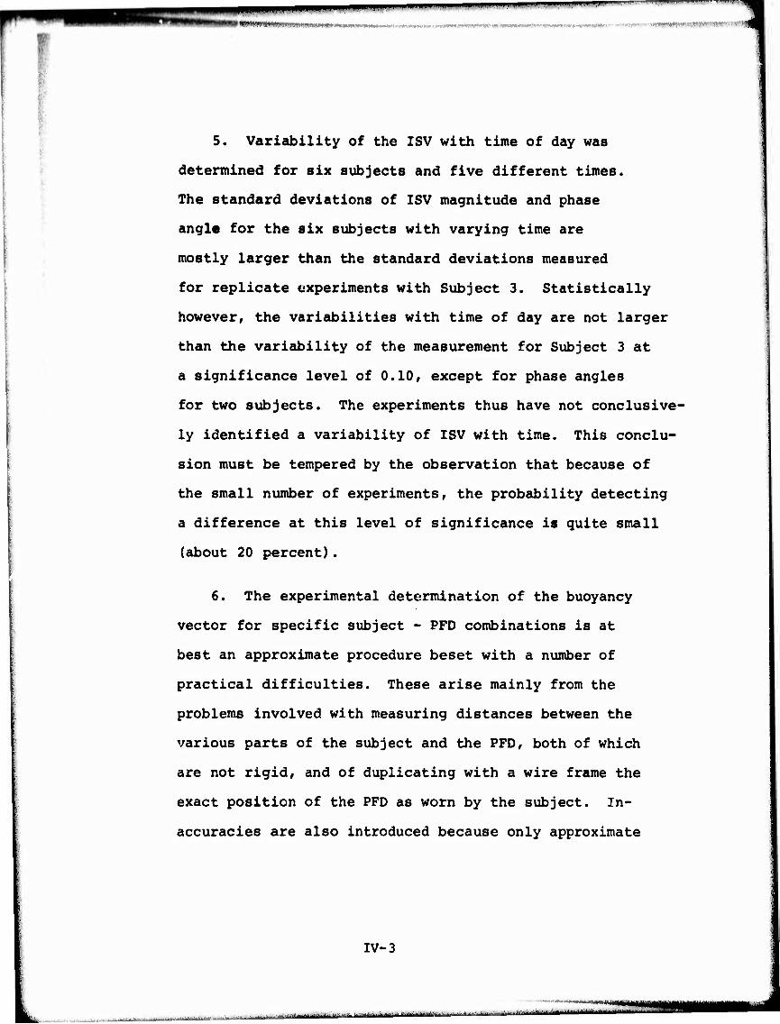
5. Variability of the ISV with time of day was
determined for six subjects and five different times.
The standard deviations of ISV magnitude and phase
angle for the six subjects with varying time are
mostly larger than the standard deviations measured
for replicate experiments with Subject 3. Statistically
however, the variabilities with time of day are not larger
than the variability of the measurement for Subject 3 at
a significance level of 0.10, except for phase angles
for two subjects. The experiments thus have not conclusive-
ly identified a variability of ISV with time. This conclu-
sion must be tempered by the observation that because of
the small number of experiments, the probability detecting
a difference at this level of significance is quite small
(about 20 percent).
6. The experimental determination of the buoyancy
vector for specific subject - PFD combinations is at
best an approximate procedure beset with a number of
practical difficulties. These arise mainly from the
problems involved with measuring distances between the
various parts of the subject and the PFD, both of which
are not rigid, and of duplicating with a wire frame the
exact position of the PFD as worn by the subject. In-
accuracies are also introduced because only approximate
IV-3
■ ' r ■iriir-"'-*"'"'-' i m ■■■-■'■ ■-■-'■■■■ — —"

mwpiwwpwwwuww'ww^^ um iimiBiiiii
procedures are available for determining the locations
of the center of the above-water volume of the subject
and the center of buoyancy of the device, even if the
various distances were measured without any error.
7. When equilibrium flotation angles are computed
from measured values of ISV, LV, and BV, the corres-
pondence with observed flotation angles is extremely
poor with differences of over 100 degrees being common
(Table 12). In only 6 of 38 cases were the differences
in angles less than 20 degrees, and in only 11 cases were
the differences less than 4 5 degrees.
8. A sensitivity analysis of the theory showed
that when the resultant stiffness vector (RSV) has a small
magnitude, the inherent variability of the measurements
of ISV and LV and small experimental errors in BV could be
responsible for the observed lack of agreement between
calculated and observed equilibrium angles (Tables 13 and 14).
When the magnitude of RSV is large however, very large
relative errors in the measured quantities would be required
to cause the existing differences between the calculated
and observed equilibrium angles. Since there seems to be no
correlation between the magnitude of the resultant stiffness
vector and the inaccuracy of the predicted angle, it is
probable that large relative errors in some measured quantities.
IV-4
..IM»

^„^■„„nnHHi»!..!!..,« ., »win .UM ii ^mmymmmmmi «
as well as inherent variabilities in ISV and LV, are
responsible. It must be pointed out, however, that the
true magnitude of RSV is not known for any of the
experiments. It is concluded therefore that inherent
inaccuracies in the measurements used in this work for
the various vector quantities are too great to permit
useful predictions of equilibrium angle using the flota-
tion theory of Reference 1. The nature of the experiments
suggests that the procedure for determining buoyancy vector
is the most probable source of large errors. However,
in certain cases, the assumption that the center of volume
of the above-water part of the subject is located at the
external meatus (ear) may introduce large errors in both
LV and BV, and these may be additive.
9. Because of the inherent inaccuracy of the measure-
ment of center of buoyancy of partially emerged PFD's,
and the extreme sensitivity of the flotation theory to
small experimental errors in some cases, direct measure-
ment of center of buoyancy does not appear to be a worth-
while approach to evaluation of PFD effectiveness.
gation show the AK-1, Design 3, Fibrous Glass, and Hybrid
Devices to be approximately equal in effectiveness to
float the subjects at large negative angles, that is
IV-5
f 9 ■
10. The limited comparisons possible in the investi-
^„ .„ - ..■,... ..,.,„„ -^.^ i.,.....^...^ ...■■>■■,■,■... „„.j.^«!««^ —-~ . -. —■*-.: --■ •■ " " " ' ""'
I - I ■•
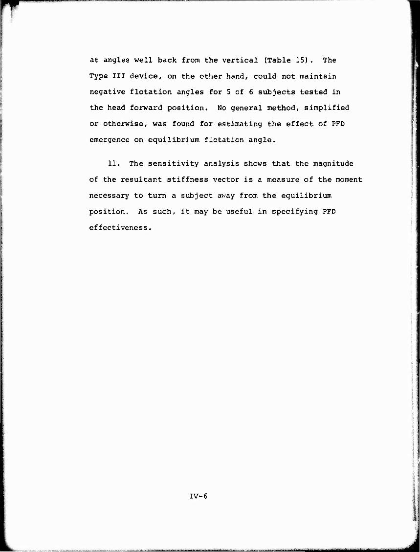
at angles well back from the vertical (Table 15). The
Type III device, on the other hand, could not maintain
negative flotation angles for 5 of 6 subjects tested in
the head forward position. No general method, simplified
or otherwise, was found for estimating the effect of PFD
emergence on equilibrium flotation angle.
11. The sensitivity analysis shows that the magnitude
of the resultant stiffness vector is a measure of the moment
necessary to turn a subject away from the equilibrium
position. As such, it may be useful in specifying PFD
effectiveness.
IV-6
.■..,.,... - „.■■..»,„ , i ii -- ^.--..; 1 jjgn .
^—^-^^^-.—p, ^ ^m l^ipil I IHIIM-LJ.HIIII lll,ll||lt,/Tr>p.
■ ■ ■ ' ■ . ■ ■ ■ ■ ■
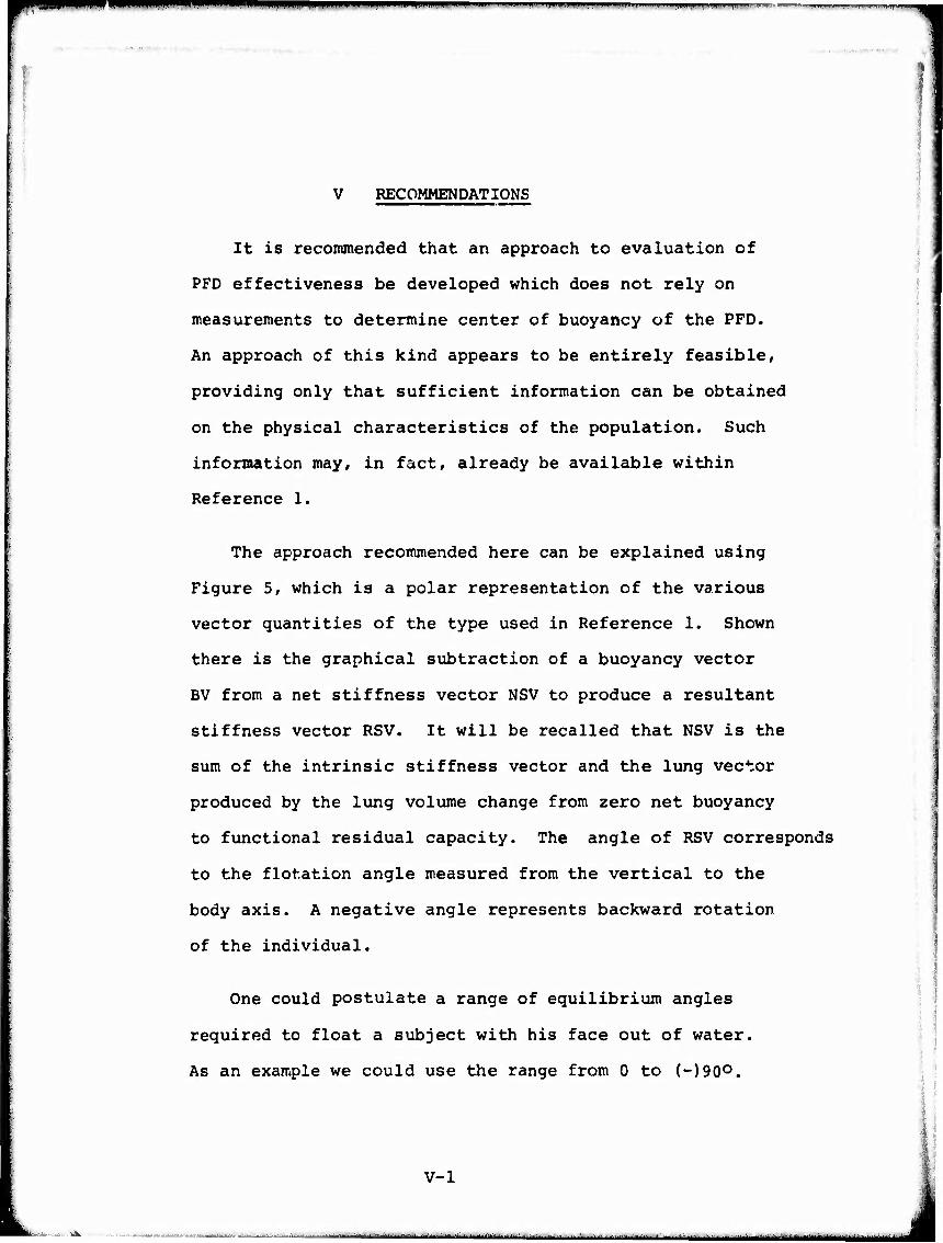
V RECOMMENDATIONS
It is reconunended that an approach to evaluation of
PFD effectiveness be developed which does not rely on ■
measurements to determine center of buoyancy of the PFD.
An approach of this kind appears to be entirely feasible,
providing only that sufficient information can be obtained
on the physical characteristics of the population. Such
information may, in fact, already be available within
Reference 1.
The approach recommended here can be explained using
Figure 5, which is a polar representation of the various
vector quantities of the type used in Reference 1. Shown
there is the graphical subtraction of a buoyancy vector
BV from a net stiffness vector NSV to produce a resultant
stiffness vector RSV. It will be recalled that NSV is the
sum of the intrinsic stiffness vector and the lung vector
produced by the lung volume change from zero net buoyancy -
to functional residual capacity. The angle of RSV corresponds
to the flotation angle measured from the vertical to the
body axis. A negative angle represents backward rotation
of the individual.
V-l
'-' l"^l■^ " '- ' ■■ — ■■■■■-■- — -.■■ ■■■■.■ ■ -^.—■^.M|1^iitM|Mt
One could postulate a range of equilibrium angles
required to float a subject with his face out of water.
As an example we could use the range from 0 to (-)90o.
'-" —""
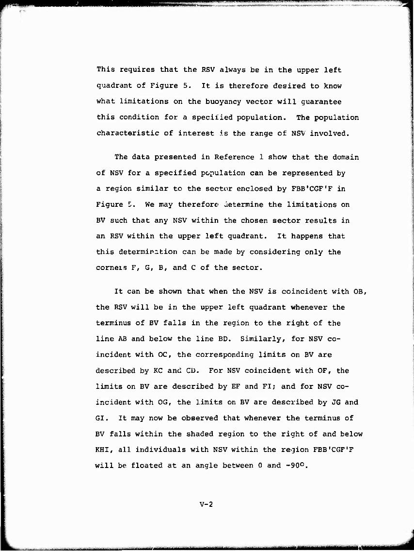
This requires that the RSV always be in the upper left
quadrant of Figure 5. It is therefore desired to know
what limitations on the buoyancy vector will guarantee
this condition for a speciiied population. The population
characteristic of interest is the range of NSV involved.
The data presented in Reference 1 show that the domain
of NSV for a specified population can be represented by
a region similar to the sector enclosed by FBB'CGF'F in
Figure 5. We may therefore determine the limitations on
BV such that any NSV within the chosen sector results in
an RSV within the upper left quadrant. It happens that
this determination can be made by considering only the
corners F, G, B, and C of the sector.
It can be shown that when the NSV is coincident with OB,
the RSV will be in the upper left quadrant whenever the
terminus of BV falls in the region to the right of the
line AB and below the line BD. Similarly, for NSV co-
incident with OC, the corresponding limits on BV are
described by KG and CD. For NSV coincident with OF, the
limits on BV are described by EF and FI; and for NSV co-
incident with OG, the limits on BV are described by JG and
GI. It may now be observed that whenever the terminus of
BV falls within the shaded region to the right of and below
KHI, all individuals with NSV within the region FBB'CGF'F
will be floated at an angle between 0 and -90°.
V-2
i i MII 11 Mr" ,

^ ■ ' ■■w —^"W
■
As mentioned, it is not considered feasible to
determine BV, therefore an indirect approach is required.
This approach can rely on the fact that if individuals with
NSV's equal to OG and OC are both floated at angles between
0 and -90O, then the terminus of BV must bt in the shaded
region, and the desired condition on 9 will be satisifed
for the population of interest.
In principle then, it is possible by this method to
evaluate PFD effectiveness for a given population using only
two tests with individuals with specified net stiffness
vectors. In practice, however, the procedure is complicated
by the effects of body size and weight, and the variation
of buoyancy vector with flotation angle. These problems
are not insurmountable provided that sufficient experimentation
can be done over the range of body characteristics of interest
to determine which limiting experiments should be performed
to take account of these extraneous effects. It appears
that independent variations of body size, weight, and NSV
will be required for these experiments.
In view of the latter statement, it is recommended that
the feasibility of developing a mannequin (or several
mannequins) which can embody the desired range of variables
be investigated. The data of Reference 1 on body character-
istics should be used to the fullest extent possible in
V-3
■ ■ - '— s=s
■•■»-^■^ I" I I " '"»
this work. Assxuning a favoreible outcome, a prototype
mannequin should be developed and pilot experiments carried
out with it. Ideally, the mannequin should be designed
for independent variation of NSV, weight, and physical
size of the torso area, but more than one mannequin may
be required to accomplish these goals. It may be observed
that the mannequin need not simulate the human form except
as it affects the fitting of the PFD. A simple frame with
movable weights and floats and a PFD mounting frame would
seem to be entirely adequate.
Experiments with the mannequin(s) and human subjects
will indicate the correct approach and its reliability. At
some point within this sequence of development it may be
necessary to obtain more information on human body character-
istics and/or to investigate the confidence limits for the
NSV data available in Reference 1.
This approach holds promise of providing a means to
evaluate equilibrium flotation angle using a few well-
defined experiments without the need for human subjects.
It may also be possible to perform other evaluations by
a similar technique, such as determining the ability of
a PFD to turn an individual from a face-down to a face-up
position. Although it does not appear possible, nor desira-
ble, to accurately measure the magnitude of the resultant
V-4
Ml, -.-I-.
—?»

r i ■ 1
stiffness vector, it may be worthwhile to determine
stability of the equilibrium position by measuring the
rate of change of righting moment with angular displacement.
V-5
-■ ■ i - ■
"■■•»-«»■•TU ■liaiiiintaiMiiiii.^
■ -- i ■ - ■
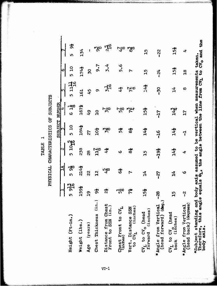
Wtßmwm* IUI»««^- ——""—- mmmmmmm
mnwifMmm ■—. nn.iMi-"
9
>o
-1
f^
OJ
ON
IA
O H
in
SS in
to
in
■ow
in
iHOO Hm
in
trte HM HM
ON
in
I ON
. HIOO HN M- H f-
VO H <*■
.1 *$
■d- o
H
a\ m
ivo H in o>
H
tn
h-IOO o m
<r r*» mico (ß £- o tr\ H CVJ H
CO MOO ^ m oo H <r OJ CVJ H
rJ cvj
in o> H H
OJ
ON
iniQD
OJ
M0O ^00 Ky
VO in
in
vo
«
HIOO in
MW
C'-IOO »OM" in t^-
00
00
in
in
in
H
in H
HM in H
OJ OJ
I
«3 i
o tn
i
H I
vo 1
I
I
I
Hv in
HN in H
row
Hw
H
Hm
H
in
co
00
VO
OJ
ß ^ i
•p
■P
■S •H 0)
(0
H
•H
(0 0)
0)
<
•H
(0 CO 0»
'w 5 ü •H
■P (0 0) X! u
co . 0) c
6s SZ oto (HCO
<H O
ü
9 c p o co ti •Hfri Q
O
o ■p
■p c o
*l cotJ 0)6 ä3
SSt0 co a)
0 0) c
co
Q> u e
•p o IHP 0) >
- Hl
S- wi o ü
H
O > u -o
u O (0
^E ^O
> <H ü
•H •P^-s un a> (i > (0
o o <H
•O a> co H <D bOÄ
5^
^^ J3
O ■P X
o > .o ü
VI-1
._ -■ ■ ■ < ■ ■■- „^^^.i^-^^^-^-m-..«» MM^MataMHMHMaHMMMHMMMai
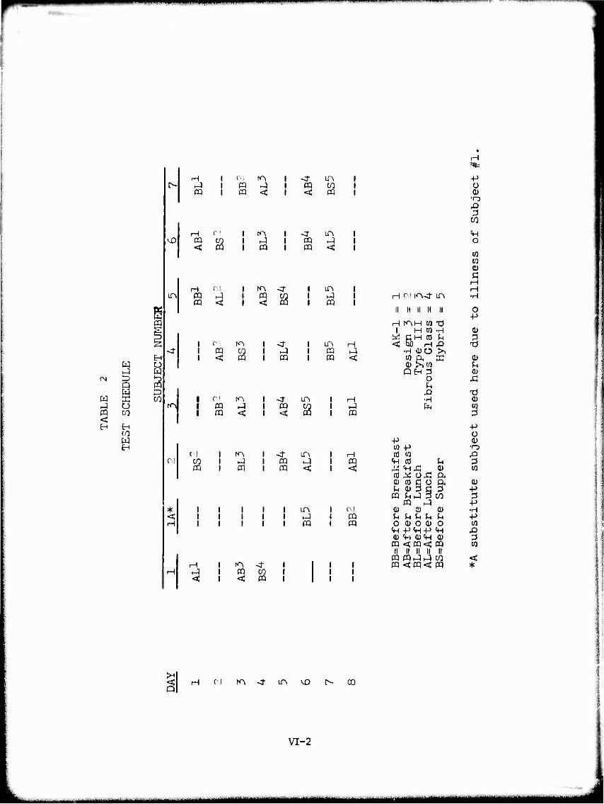
!N
W
m <
s
O
CO
t^-
^ H 1 OJ r^ i <r in i J 1 ffl H i m W 1 CQ i cq <: i < CQ 1
vO H r1 1 ro 1 <t m i cq CO 1 -1 CQ •^ ' < ffl 1 CQ 1 CQ < l
LA CM
CQ CQ
r<A
CM
I CQ t < ^
I in I ^ I CQ
1 0' to i <r I in rH 1 CQ CQ i ^ 1 CQ -1 1 < ffl 1 CQ 1 CQ <
1 CM K\ 1 <f LPv I ffl -J 1 CQ CO 1 cq < 1 < CQ
CM l ro 1 <(• LA CO 1 KJ 1 CQ -1 CQ 1 CQ 1 CQ <
in
CQ
H l ro <r HJ 1 ffl CO < i <: CQ
CQ
CQ <
C\J CQ CQ
+J Ü 0) •rj X) 3
CO
<H o w w 0) Ö H H
H c I rn-ct in •H
II li ii ll II o -p
H mM w -ö 1 M w •H 0)
^SM^ fl 3 x> n
•rH (DO >, W (X X Q)
u QH 3 0)
O Ä U X) x) •H a) PM w
3
Ü -P 0) W +J •o CO w XI
«H CO u 3 ü MX; V w to ^ ox: ft (D CO ß Ü ft 0) ^t Q> 3 c 3 ■p
CQ ^ J 3 CO 3 CQ J -p
0) o 0) •H u u u u ^ ■p OCDOO) o w Vl +^ «H -P «H XI 0) «H OVl 0) 3
CQ <cq<; ff) to II II II II II
CQ ffUJ CQ <;cq<^
CO < cq *
<; H ci m -t m vD t^ co PI
L VI-2
- ■ - ■ — - MM^MMiMHMMMMHMaHMMM^MMHI ■MMWHMiMIMMMMai
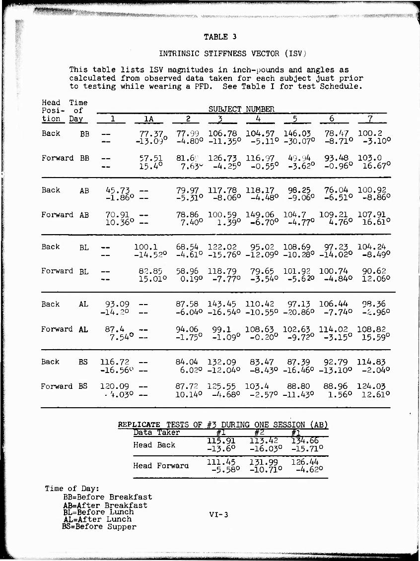
«ff If^t^iV,.,^,,,,,
mmmmmmmmm i
11 "■■ i ■■ ii i II ■ I ■ I M
KUWWWW»»*»» ««Hmr"
I TABLE 3
i
INTRINSIC STIFFNESS VECTOR (ISV)
This table lists ISV magnitudes in inch-pounds and angles as calculated from observed data taken for each subject Just prior to testing while wearing a PFD. See Table I for test Schedule.
Head Time Posi- of tion Day 1_
Back BB
Forward BB
SUBJECT NUMBER 1A JL
77.37„ 77.99 106.78 104.57 146.03 78.47 100.2 -13.09° -4.80° -11.35° -5.11° -30.07° -8.71° -3.10°
57.51 15.4°
81.6l 126.73 116.97 49.94 93.48 103.0 7.63° -4.25° -0.55° -3.62° -0.96° 16.67°
Back AB 45.73 -1.86°
79.97 117.78 118.17 98.25 76.04 100.92 -5.31° -8.06° -4.48° -9.06° -6.51° -8.86°
Forward AB 70.91 10.36°
78.86 100.59 149.06 104.7 109.21 107.91 7.40° 1.39° -6.70° -4.77° 4.76° 16.61°
Back BL
Forward BL
100.1 68.54 122.02 95.02 108.69 97.23 104.24 -14.52° -4.61° -15.76° -12.09° -10.28° -14.02° -8.49°
82.85 58.96 118.79 79.65 101.92 100.74 90.62 15.01° 0.19° -7.77° -3.54° -5.620 _4.84o 12.06°
Back AL 93.09 -14.2°
Forward AL 87.4 7.54°
87.58 143.45 110.42 97.13 106.44 98.36 -6.04° -16.54° -10.55° -20.86° -7.74° -2.96°
94.06 99.1 108.63 102.63 114.02 108.82 -1.75° -1.09° -0.20° -9.72° -3.15° 15.59°
Back BS
Forward BS
116.72 -16.56^
120.09 - '4.03°
84.04 132.09 83.47 87.39 92.79 114.83 6.02° -12.04° -8.43° -16.46° -13.10° -2.04°
87.72 125.55 103.4 88.80 88.96 124.03 10.14° -4.68° -2.57° -11.43° 1.56° 12.61°
REPLICATE TESTS OF #3 DURING ONE SESSION (AB) ~- Data Taker #1 W j #1 '
115.91113.42134.66 Head Back
Head Forward
Time of Day: BB=Before Breakfast AB=After Breakfast BL=Before Lunch AL=After Lunch BS=Before Supper
-13.6° -16.03° -15.71°
111.45 131.99 126.44 -5.58° -10.71° -4.62°
VI-3
w,™ ■ ■- ..- ■■■ -. —.„..■ .. ■irililiniMfMiiiiiMii i i imm imaj—mmtMaiiMi MMHBMMM
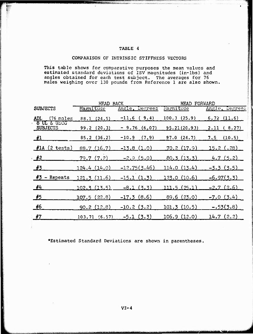
*■■■'
1
^JJJJ£^2Z~~Z~ : ■••"^-~r" —- ■ - " m>* •
MVUNWlTVMI
TABLE 4
COMPARISON OF INTRINSIC STIFFNESS VECTORS
This table shows for comparative purposes the mean values and estimated standard deviations of ISV magnitudes (in-lbs) and angles obtained for each test subject. The averages for 76 males weighing over 130 pounds from Reference 1 are also shown,
HEAD BACK HEAD FORWARD SUBJECTS Magnitude Angle. Decrees Marnitudo An/Uo« De/rree" |
ADL (76 males 88.1 (24.5) -11.6 ( 9.4) 100.3 (25.9) 6.72 (11.6) • Ö UL & Uicü SUBJECTS 99.2 (20.3) - 9.76 (6.07) 95.21(20.93) 2.11 ( 8.27)
#1 85.2 (36.2) -10.9 (7.9) 97.0 (24.7) 7.5 (10.5)
#1A (2 tests) 88.7 (16.7) -13.8 (1.0) 70.2 (17.9) 15.2 (.28)
. #2 79.7 (7.2) -2.2 (5.0) 80.3 (13.3) 4.7 (5.2)
#3 124.A (14.0) -12.75(3.46) 114.0 (13.4) -3.3 (3.5)
#3 - Repeats 121.3 (11.6) -15.l'(1.3) 123.0 (10.6) -6.97(3.3)
#4 102.3 (13.5) -8.1 (3.3) 111.5 (25.1) -2.7 (2.6)
#5 107.5 (22.8) -17.3 (8.6) 89.6 (23.0) -7.0 (3.4)
#6 90.2 (12.8) -10.2 (3.2) 101.3 (10.5) -.53(3.8)
#7 103.71 (6.57) -5.1 (3.3) 106.9 (12.0) 14.7 (2.2)
♦Estimated Standard Deviations are shown in parentheses.
VI-4
■ ■■■ ■-- ■ - i —--^^-m aMMMaMMMSMMMB MMMMMM
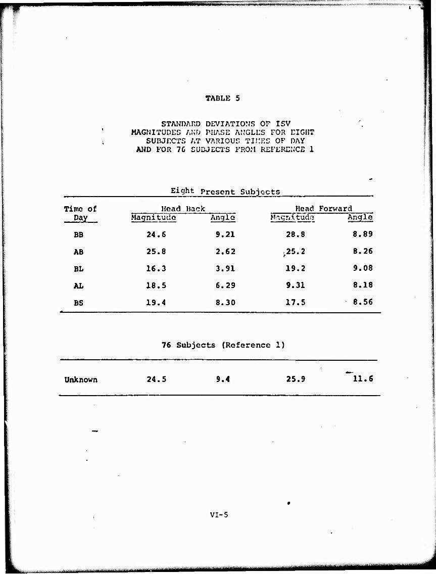
TABLE 5
STANDARD DEVIATIONS OF ISV MAGNITUDES AND PHASE ANGLES FOR EIGHT
SUBJECTS AT VARIOUS TII1ES OF DAY AND FOR 7C SUBJECTS FROM REFERENCE 1
Eight Present Subjects
Time of Head Hack Head Forward Day Magnitucie
24.6
Angle
9.21
MngnitudQ
28.8
Angle
BE 8.89
AB 25.8 2.62 ,25.2 8.26
BL 16.3 3.91 19.2 9.08
AL 18.5 6.29 9.31 8.18
BS 19.4 8.30 17.5 8.56
76 Subjects (Reference 1)
Unknown 24.5 9.4 25.9 11.6
VI-5
■ -- ■■ -- ■■■■■' ..^-.....-^ u-^tMMMtfT^ M^MBHMMMBMM MMMM

mm —~-
TABLE 6
90 PERCENT CONFIDEIJCE ÜJTEHVALS FOR THE RATIO OF STANDARD DEVIATIONÖ OF
PRESENT DATA AND REFERENCE 1 DATA FOR ISV
Quantity
Magnitude
Head Position
Back
Forward
Time of 90% Confidence Interval Day For S^/S^
BB 0.68 to 1.94
AB 0.71 to 2.02 -
BL 0.45 to 1.29
AL 0.52 to 1.46
BS 0.53 to 1.52
BB 0.75 to 2.12
AB 0.65 to 1.86
BL 0.50 to 1.42
AL 0.24 to 0.68
BS 0.46 to 1.30
Angle Back
Forward
BB
AB
BL
AL
BS
BB
AB
BL
AL
BS
0.66 to 1.88
0.19 to 0^53
0.28 to 0.80
0.45 to 1.29
0.59 to 1.69
0.52 to 1.46
0.48 to 1.36
0.52 to 1.48
0.48 to 1.36
0.50 to 1.42
VI-6
_l___Mi_ ■■■■■■ : ' ■ - -■-- -'■ - ■- ii iiMMtiiiii !- ~ - -

«IW yWW^'^WIiWWW^-.lilliMmM^ilJWWWIWWW WllPf"" ■"•«-
TABLE 7
STANDARD DEVIATIONS FOR THE ISV OF SUBJECT 3 IN THREE REPLICATE EXPERIMENTS
Standard Deviation Head Position Magnitude Phase Angle
Back 11.6 1.32
Forward 10.6 3.27
TABLE 8
95% CONFIDENCE INTERVALS FOR THE STANDARD DEVIATION OF REPLICATE MEASUREMENTS OF THE ISV OF SUBJECT 3
95% Confidence Interval Head Position Magnitude Phase Angle
Back 5.31 to 56.4 0.60 to 6.42
Forward 4.85 to 51.2 1.50 to 15.89
VI-7
- - , - -
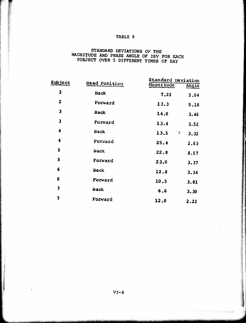
TABLE 9
STANDARD DEVIATIONS OF THE MAGNITUDE AND PHASE ANGLE OF ISV FOR EACH
SUBJECT OVER 5 DIFFERENT TIMES OF DAY
Subject Head Position
2 Back
2 Forward
3 Back
3 Forward
4 Back
4 Forward
5 Back
5 Forward
6 Back
6 Forward
7 Back
7 Forward
Standard Deviation Magnitude Angle
7.22 5.04
13.3 5.18
14.0 3.46
13.4 3.52
13.5 ' 3.32
25.4 2.63
22.8 8.57
23.0 3.37
12.8 3.34
10.5 3.81
6.6 3.30
12.0 2.22
VI-8
■ - ■ - - - — -■ ■ ■M^^M^KM _^^^m
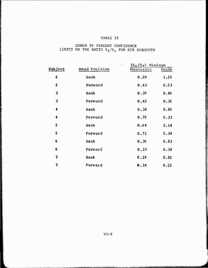
TABLE 10
LOWER 90 PERCENT CONFIDENCE LIMITS ON THE RATIO Sj/Sj. FOR SIX SUBJECTS
Head Position (S
Ma i/Sr) Minimum
Subject cjniuiio ,» Angle
2 Back 0.20 1.25
2 Forward 0.43 0.53
3 Back 0.39 0.86
3 Forward 0.42 0.35
4 Back 0.38 0.80
4 Forward 0.79 0.33
5 Back 0.64 2.14
5 Forward 0.71 0.34
6 Back 0.36 0.83
6 Forward 0.33 0.38
7 Back 0.19 0.82
7 Forward 0.34 0.22
VI-9
- *-L*^**^^~IJ*i**äi~*~*~****

TABLE 11
VARIATION IN LUNG VECTOR FOR TEST SUBJECT NO. 3
Subject Date & Time*
10/3 3BB
10/3 (Repeat)
10/8 3AB
10/8 (Repeat)
10/11 3BL
10/4 3AL
10/9 3BS
10/15* 3AB
10/15* 3AB
10/15* 3AB
10/15* 3AB
10/15* 3AB
LV Mean =
Std Dev =
f Head Forward Head Back AVL
(liters) (inches) (d ÖL
16
(inches) (dep;.)
Lung Vector (LV) Magnitude
14.5 14.5 -1 2.74 87.6 in-lbs
1.35 43.2
1.86 59.5
1.21 38.4
1.2 38.4
2.73 87.3
1.93 61.7
2.1 67.1
2.3 73.5
1.52 48.6
2.15 68.7
l r > i i 2.58 82.5
63.01
18.0
^V^ - Change in lung volume from that yielding zero net buoyancy in fresh water to functional residual capacity. For Subject No. 3, the change was always a decrease in volume (positive change).
dL - Measured distance in inches between the subject's center of lung volume and center of ear. For Subject No. 3 dL happened to be the same for both head-forward and head-back positions.
LV = PwAVLdL where P^ 2.2046 lbs/litre
*N0TE: Five consecutive measurements taken during one After Breakfast session. Mean LV for these was 68.08 with a Standard Deviation of 12.4.
VI-10
^«■MMMM M^^MMHaMMHIIBMIMaMaHaMM

CT"-»~~-—««•—
lABlE 12
simu« oi ■ cwruATiD AND oiumtu RESULTS
PFDU) I.ury v.-ctor
ZnUirtBic St i flrv Ü3 V'ctcr
Mi . Anyle lln-lbä) 7ü'.-JIVI.'S)
Buoyancy Vi-ctrr MM. At.'jlo
Rsultant stiffrcsa vector
Miy. Ar.nk- TTrvTEi) (U-'ijnva)
Observed Djuilibnum
Suhjlll - .v.cjTTT Angle (ÜLHJIWS) ^Degrees)
1-n AK-1 - 14.2 - 2 93.09 - 14.2 - 95.1 23.5 61.3 -100.5 -40
l-r AK-1 - 20.5 - 28 87.4 7,54 - 97 3.5 32 152 2
l-F III - 50,6 - 28 70.91 10.36 -198 - 29.7 199 138 49
l-F F.G. 17.4 - 28 120.09 - 4.03 -225.1 - 25.9 40 -16.8 -25
1-B F.G. - 4.30 - 2 116.72 - 16.56 -148.9 - 9.5 261 - 13 -41
1A-F 13 26.9 - 27 57.57 15.4 -268 - 15.9 194 157 -39
1A-B »3 17.5 6 77.37 - 13.09 - TV 14.4 39 - 65 -34
1A-F Hybrid - 16.3 - 27 82.85 15.01 - 85 48 35 - 76 -43
2-n III - 80 4 84.04 6.02 -114 26.1 104 -155 -52
2-B F.G. 13.4 4 77.99 - 4.8 - 40 20.7 57 - 20 -46
2-F Ill - 49.6 - 19.5 87.72 10.14 -136 24.9 87.5 -163 44
2-F F.G. - 'i.9 - 19.5 81.69 7.63 - 59 - 59.7 82 92 -50
3-B AX-1 12.8 - 1 122.02 - 15.76 -100 15 68 - 61 -42
3-B «3 60.7 - 1 106.78 - 11.35 -294 8.7 142 -152 -42
3-B III 34.5 - 1 143.(5 - 16.54 -168 15.1 86 - 84 -42
3-B F.G. 37.4 - 1 117.78 - 8.06 -154 1.2 21 - 90 -20
J-F AK-: 15.3 - 16 118.79 - 7.77 - 92 10.3 56 - 41 -41
3-F • 3 62 - 16 126.73 - 4.24 -274 - 2.6 88 -171 -38
3-F III 44.8 - 16 99.1 - 1,09 -117 10 44 - 52 34
>r F.G. 39.3 - 16 100.59 1,39 -148 - :5 36 114 -24
4-F Wt-1 - 27.3 - 17 108.63 - 0,2 - 86 1.9 6 126 -34
4-F 13 X09.0 - 17 149.06 - 6.7 -297 - 12 40 163 -39
4-P Hybrid - 18.8 - 17 116.97 - ,55 -113,7 0.6 15.04 168 -23
5-' III 46.4 - 30 104.7 - 4.77 -134 - 14 15 2 0
s-r F.G. 35.4 - 30 88.8 - 11.43 - 83 - 63.9 90 26 -44
6-F AK-1 - 17.5 - 24 109.21 4,76 - 96.8 - 19.2 48.0 83.4 -38
6-F n 18.2 - 24 88.96 1,56 -258 1.6 153 -175 -22
6-F in - 14.2 - 24 100.74 - 4,84 -137.5 - 11.2 54 153.4 5
6-F Hybrid 21.5 - 24 114.02 - 3,1. - 90 5.4 50 - 28 -«7
€-8 Hybrid 28.7 18 106.44 - 7,74 - 95.3 33 78 - 47 -39
6-F F.G. 13.2 - 24 93.48 - 0,96 . - 71.1 - 66.2 96 37 -48
7-B Ill 13.2 4 98.36 - 2.96 -183 17.5 87 -137 -23
7-B hybrid 3.3 4 114.83 - 2.04 - 68 24.6 56 - <a -32
7-r AK-1 - 9.92 - 22 90.62 12,06 -101.0 5.8 24,4 149 -21
7-F #3 -'12.3 - 22 103 16.67 -321 13.4 229 -170 -27
7-F III - 20.5 - 22 108.82 15,59 -143 2.1 65 151 - 1
7-F Hytirid 3.4 - 22 124.03 12,61 - 85 13.9 42 7 -22
7-e AK-1 - 6.15 4 104.24 - 8.49 -U8.8 29.5 74.6 - 95 -33
(1) B suffix irdioau-s "Hood B.jcic"i F suffuc indicates "llcad Forward".
(2) MDTVpe»: AK-1 - St,ir.dari Ouist Oii/irrl TflC II buoyant vest. 13 - Crjcrt Oiu-d fi(% n-Ajd T,-.r I vt-st iK.i;«>.) . F.f,. - Crvu t Cuanä AJVTO'äSI MV I '■»-St (fiber ^lass). Ill - Ovi't Guird Äjiprcwxitl. ListrJ Eiecial rurpoac Btcyant tevloo (Type III). Hybrid - IN;» rirontal ITC furmshed by Coast O-iari.
VI-11
'- ^^MMM ^^^ttmmmmm

TABLE 13
ERRORS IN CALCULATED EQUILIBRIUM ANGLE ASSOCIATED WITH ERRORS IN ISV AND LV MEASUREMENTS FOR SUBJECT 3
Error Caused by One Standard Deviation in;
Head ISV ISV LV Device Position Magnitude Angle Magnitude
Fibrous Glass Back 30.2° 1.0° 41.0°
Design 3 Back 2.6° 0.76° 4.8°
TABLE 14
ERRORS IN CALCULATED EQUILIBRIUM ANGLE ASSOCIATED WITH ERRORS IN BV AND LV MEASUREMENTS FOR SUBJECT 3
Error Caused by Given Increment
Device Head
Position
Back
Back
10% BV Magnitude
47.40
3.90
5° BV Angle
0.75°
9.8°
5° LV Angle
Fibrous Glass
Design 3
0.15°
1.9°
VI-12
- ■ ■■ - ■ ■ —■

TABLE 15
OBSERVED EQUILIBRIUM FLOTATION ANGLES
Personal Flotation Device
Notes:
B=Head back; F=Head forward.
Negative angle indicates body axis is back from vertical.
Instrument limitation is 64°.
*Angle which exceeds 64° back from vertical position.
Sub j . No.
Head Pos.
B F
Fibrous Glass
-41° -25°
Design 3 Hybrid AK-1 Type III
1 -40° 2°
*
49°
1A B F
-34o -39°
*
-43°
2 B F
-< -50
* *
* *
* *
-52° 44°
3 B F
-20° -24°
-48° -38°
* *
-42° -41°
-42° 34°
4 B F
*
-40° *
-39° -28° *
-34° * *
5 B F
*
-44° * *
* * *
*
0°
6 B F
*
-48° *
-22° -39° -47°
*
-38° *
5°
7 B F
* *
*
-27° -32g -22
-33° -21°
-23° - 1°
VI-13
-■■ .--...-^^...v-.--.^.^ - — ■ ■ Hitk—^-»-I-^L-.I..---*!.■■*<■* „i. ■ ! nlMtidnJ
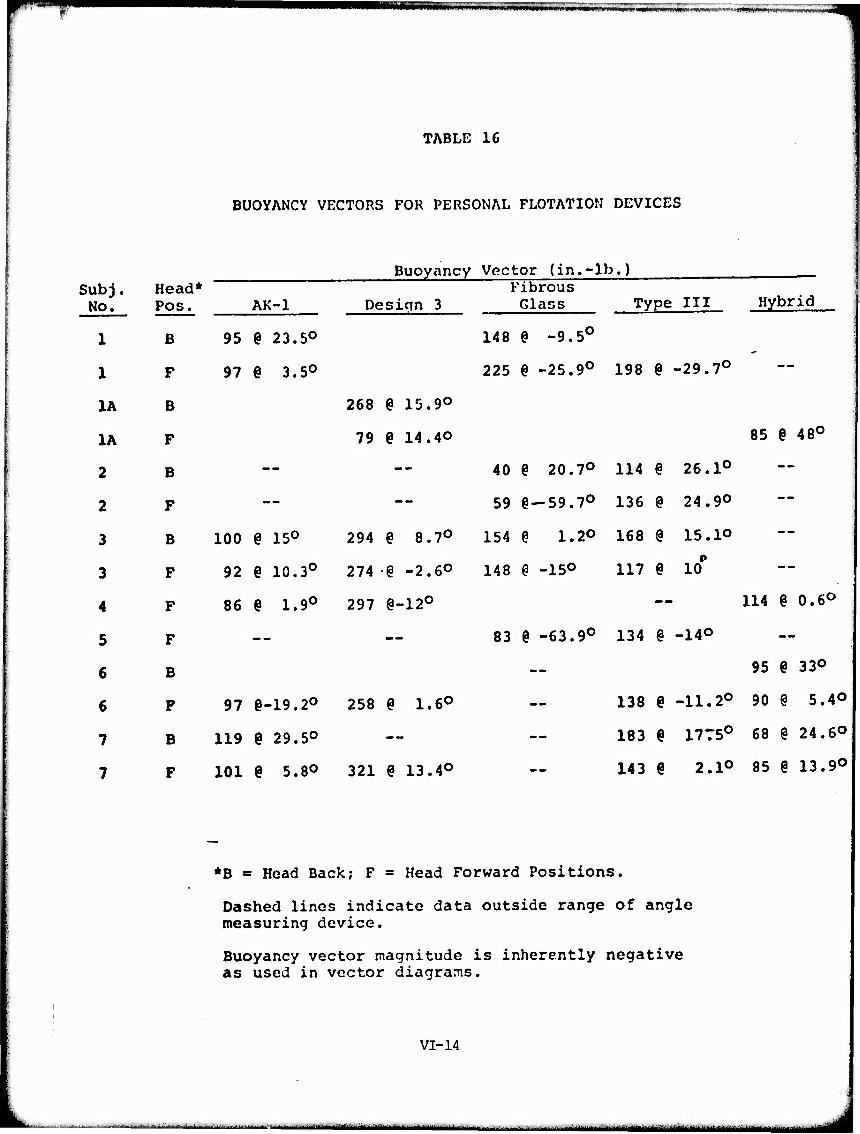
F ■ I ^ ^^T=^
TABLE 16
BUOYANCY VECTORS FOR PERSONAL FLOTATION DEVICES
Buoyancy Vector (in.-lb.) Sub j. Head* ~ " ~ ' ~ Fibrous
No. Pos. AK-1 Design 3 Glass Type III Hybrid
1 B 95 e 23.5° 148 @ -9.5°
1 F 97 e 3.5° 225 § -25.9° 198 @ -29.7°
1A B 268 6 15.9°
1A F 79 e 14.40 85 § 48°
2 B — — 40 @ 20.70 H4 @ 26.1°
2 F — — 59 §-59.7° 136 6 24.9°
3 B 100 @ 15° 294 § 8.7° 154 @ 1.2° 168 @ 15.1©
3 F 92 § 10.3° 274 e -2.6° 148 @ -15° 117 @ 10*
4 F 86 § 1.9° 297 §-12° — 114 6 0.6°
5 F — — 83 @ -63.9° 134 @ -140
6 B — 95 ? 33°
97 e-19.20 258 @ 1.6° — 138 § -11.2° 90 @ 5.4©
119 e 29.5° — — 183 € 1775° 68 @ 24.6©
101 § 5.80 321 @ 13.4° -- 143 § 2.1° 85 % 13.9©
6 F
7 B
7 F
*B = Head Back; F = Head Forward Positions.
Dashed lines indicate data outside range of angle measuring device.
Buoyancy vector magnitude is inherently negative as used in vector diagrams.
VI-14
■■■' — - -■ - — —-^.—^..■^—.: ~—^ L—-. . .. ■ ^ ■—■^ „„.„^^„^^-^

»o^p ■ -
Hum ]iii]iiii i ■ "i ■ """' ' '
■
TABLE 17
PERCENT OF AVAILABLE BUOYANCY USED BY EACH PFD TO SUPPORT TEST SUBJECT AT OBSERVED EQUILIBRIUM FLOTATION ANGLE
Personal Flotation Device fibrous
SubJ. Head AK-1 Design 3 Glass Type III Hybrid No. Pos.* De*. % DeK. % De^. % Pep. % Pep. J.
(18725) (5^.2) OT5)"^I57B) Cit.5)
1 B -AO #* -41 49 ~ ~ IF 2 41 -25 60 49 79
1A B -34 11 — -- 1A F -39 48 -43 84
2 B — — — ~ -46 37 -52 53 — — 2 F — -_ — — -50 36 44 71 — —
3 B -42 62 -42 56 -20 46 -42 84 — 3 F -41 62 -38 51 -24 45 34 54 — —
4 B — - — — - - — — 4 F -34 A8 -39 48 -64 23 — — -28 **
5 F — — — -- -44 25 0 56 — —
c R — — — — — — — — —39 ** 6 F -38 37 -22 49 -48 25 5 63 -47 42
7 B -33 ** — — — — -23 72 -32 18 7 F -21 81 -27 52 — — -1 59 -22 28
Dashed lines indicate off scale readings (equilibrium angle greater than 60 degrees).
Negative angles indicate body axis back of vertical. ( ) Buoyancy of totally submerged PFD in pounds.
*B= Head Back; F=Head Forward. ♦♦Data not determined.
VI-15
i . ■«■»
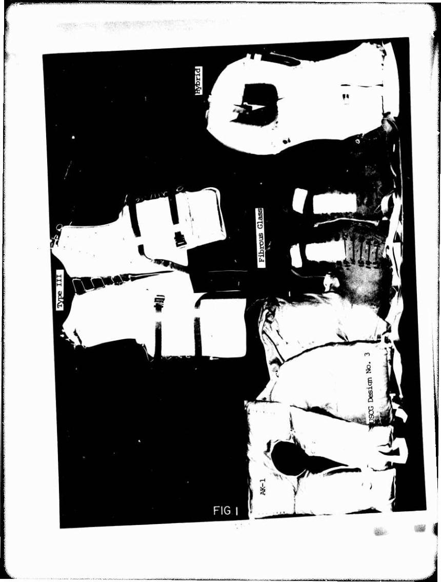
"^ l"1 J
""_ ■ '
■ ■■ — mmm n ,.,..„ ^

jll^mmimmmmmm « ■ HwmmiaiOTPNpipi IIDIII^IIJI IP« ■, .Hü i i m M ■■ m in mi i '
VI-17 4K "^^i^1*
-7 0
■ -■■■' --^■.^^.■.-^■.- —^.:.. .„■■■.■.- -—.. _:....^._-— ..-...„.^^^■..-.-..■ ..-..^—.^.■^^■^^■^■^.■.. ^ mmg .............^ .,..;—..„.-,
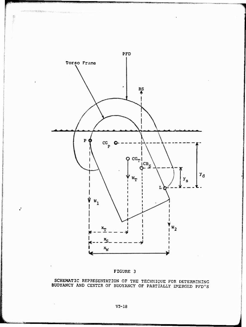
' ' ■■» ,.11. ! I ii-yi,,.!,!.,,.»,,^, ■■^y- —"-' II HWKIipu
■ ■ 1
PFD
Torso Frame
<li l*tmMmm»km*im^km*m*
-t.
FIGURE 3
SCHEMATIC REPRESENTATION OF THE TECHNIQUE FOR DETERMINING BUOYANCY AND CENTER OF BUOYANCY OF PARTIALLY EMERGED PFD'S
VI-18
L. rr=

mmti^M^i
Center Buoyancy of Emerged Material
- Center of Buoyancy of Fully Sub- merged PFD
i
Body Axis
Effective Center of Buoyancy of Partially Submerged PFD
FIGURE 4
SCHEMATIC DIAGRAM OF PARTIALLY EMERGED PFD
;
VI-19
L —-'— — ■ I j

»(ÄÄS^^-.
K
FIGURE 5
SCHEMATIC REPRESENTATION OF LIMITING VALUES OF THE BUOYANCY VECTOR
VI-20
-..i_ , —■- --■ ■ 1—i—i——— 1—l - ■■ J
pwiwim m»^—i -■»■wHffwnfw/inw^nn.^.h...,.,. mmi^mmm
■■ ' 1
t REFERENCES
1. Ano'i., "Final Report on Buoyancy and Stability Characteristics of the Human Body in Fresh Water", Arthur D. Little, Inc., Project 725106, Coast Guard Contract KDT - CG - 90, 511 - A (April 13, 1972).
2. Natrella, M. G., "Experimental Statistics", National Bureau of Standards Handbook 91 (August 1, 1963), pp. 3-26 to 3-28.
3. Ibid., pp. 4-8 to 4-9.
4. Ibid., pp. 2-7.
5. Ibid., pp. 4-9 to 4-10.
VIl-i
,. in. i , immr ' I miMriiinll III I - - J
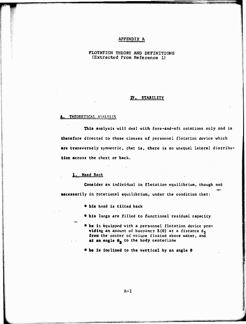
(**K«»»lWW,.l. ilp0i|i»[f>fl|W»WI«l"^Vi«**'*t
APPENDIX A
FLOTATION THEORY AND DEFINITIONS (Extracted From Reference 1)
IV. STABILITY
A. THEORETICAL ANALYSIS
This analysis will deal with fore-and-aft rotations only and is
therefore directed to those classes of personnel flotation device which
•re transversely symmetric, that is, there is no unequal lateral distribu-
tion «cross the chest or back.
I. Head Back
Consider an individual in flotation equilibrium, though not
necessarily in rotational equilibrium, under the condition that:
* his head is tilted back
* his lungs are filled to functional residual capacity
* he Is equipped with a personnel flotation device pro- viding an anount of buoyancy B(9) at a distance do from the center of volune floated above water, and at an angle 0- to the body centerline
* he Is Inclined to the vertical by an angle 9
i
I
A-l
»outturn — —" aymtti—lUwi J

»■im
IIIHIIII IM I XM«* ■— ' ' 'm
■„.'■. ■
Under thosf conditions, the subject will have five vertical
forces acting on him. These forces are diagranrned in Figure IV-I and
are specifically:
P V w o
The loss of buoyancy due to bringing the
volume V above water, acting vertically o
downward through CV (6) - the center of o
floated volume.
w T - W
The subject's weight in air acting ver-
tically downward through CG(9) - the
subject's center of mass.
The buoyancy of the total body acting ver-
tically upward through CV (9). Equal to
the subject's weight when the lungs are
inflated to provide zero net buoyancy.
p AV. w L
The change in buoyancy provided by the lungs,
in changing inflation from that yielding
zero net buoyancy to functional residual
capacity, acting vertically upward through
CAV - the center of change of buoyancy of Li
the lungs.
B(9) - The buoyancy provided by the personnel flota-
tion device acting vertically upward through
CB(e) - the effective center of buoyancy of
the device.
In each of the definitions above, where a buoyancy or a center of buoyancy
may change its value or location with changing inclination angle, the de-
pendence on 9 is indicated.
A-2
L _ ...^ .-^ . — ^-^-^ ■..,.,-...-^
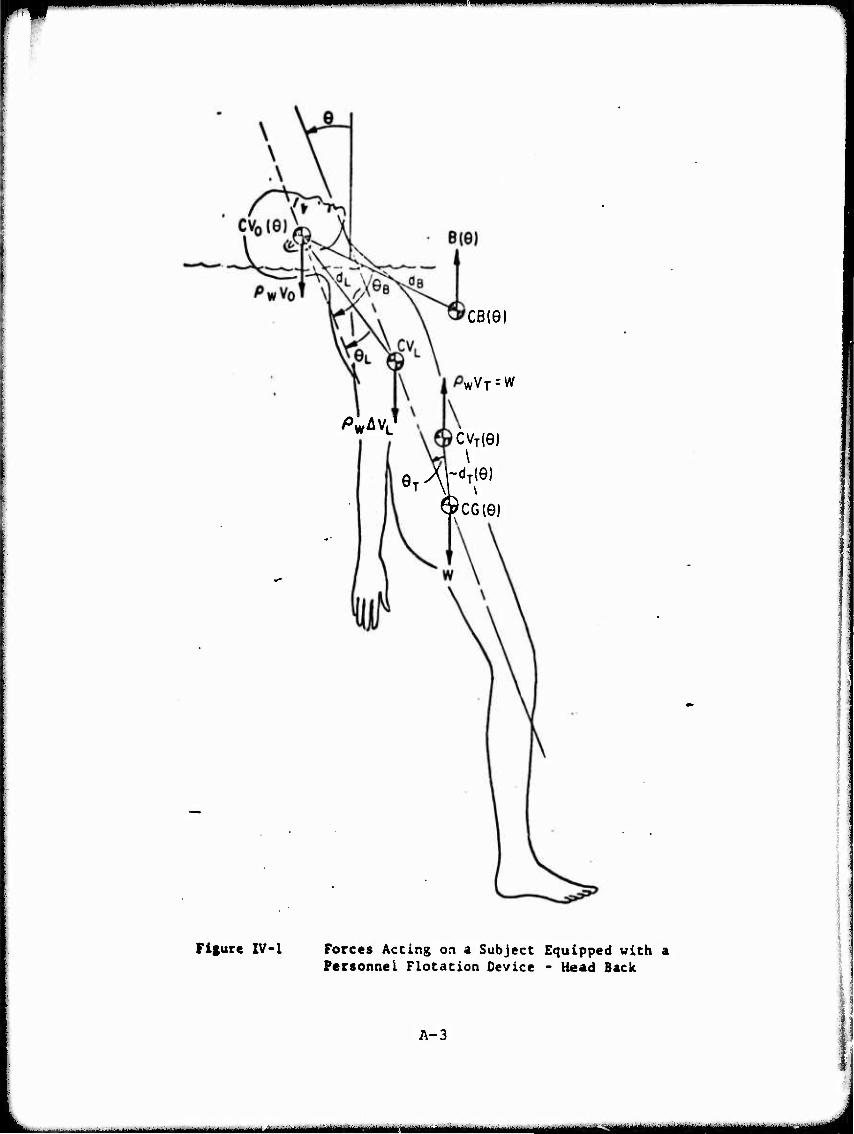
"
^■"
Cß(G)
WVT--W
PWAVL CVJO)
\
$CG(G)
Figure IV-1 Forces Acting on a Subject Equipped with a Personnel Flotation Device - Head Back
A-3
-■—i—i 1—i It MMa^aan
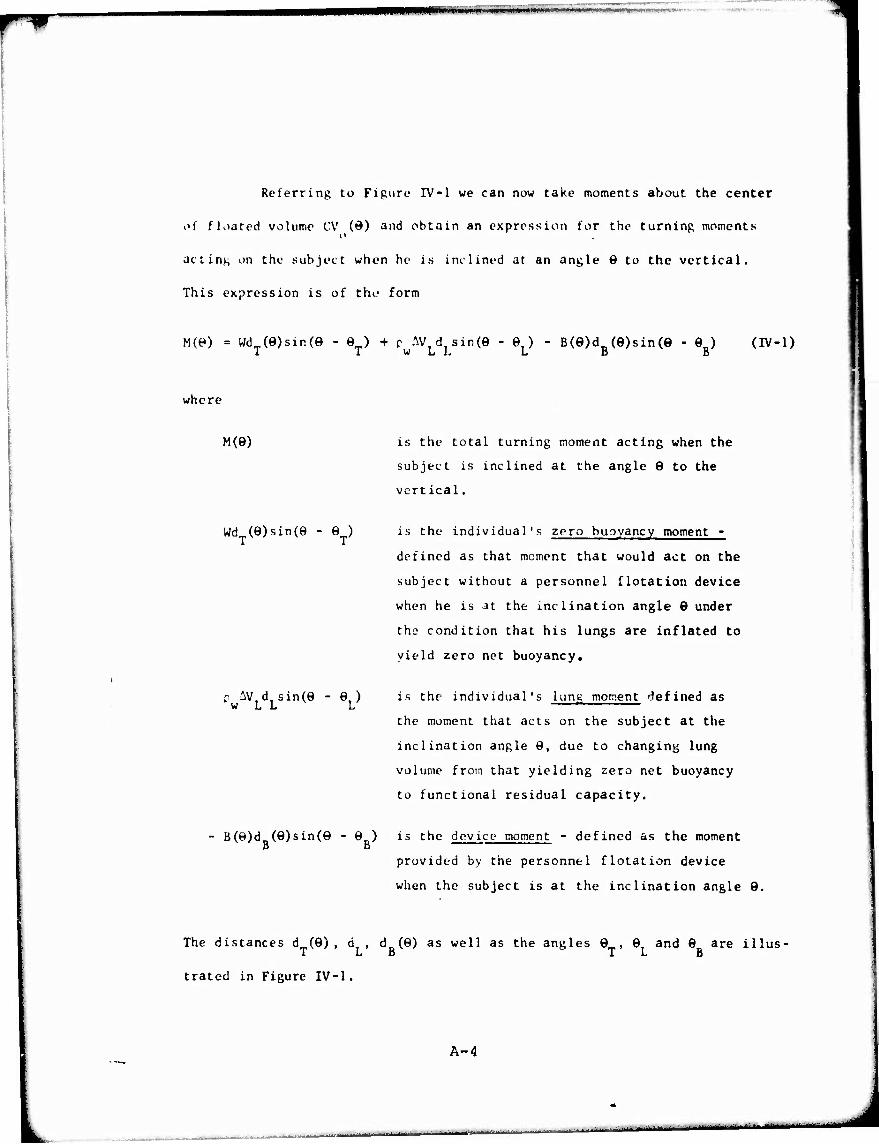
QfQIBJHUijllHJimtttmlimimiimmmßi, »*• WHilMMW'W.JlA' i'^'-^- '"^
Referring to Figure IV-1 we can now take moments about the center
of floated volume CV (ö) and obtain an expression for the turning moments o
acting on the subject when he is inclined at an angle 6 to the vertical.
This expression is of tho form
M(e) = wdT(e)sin(e - eT) + c AV d sin(0 - e ) - B(e)d (e)sin(e - ej (iv-i) 1 IWLL L D I)
where
M(e) is the total turning moment acting when the
subject is inclined at the angle 0 to the
vert ical.
wdT(e)sin(e - eT) is the individual's zero buoyancy moment -
defined as that moment that would act on the
subject without a personnel flotation device
when he is at the inclination angle 9 under
tho condition that his lungs are inflated to
yield zero net buoyancy.
D AVd sin(e - e) W L L L
is the individual's lung moment defined as
the moment that acts on the subject at the
inclination angle 9, due to changing lung
volume from that yielding zero net buoyancy
to functional residual capacity.
B(8)d (9)sin(9 - 9 ) is the device moment - defined as the moment B B
provided by the personnel flotation device
when the subject is at the inclination angle 9.
The distances d (9), d , d (9) as well as the angles 9 , 9 and 9 are illus- TLB TLB
trated in Figure IV-1.
A-4
,i ■■ ■ ■ - -■' '■ ■'* ■ ■ ^-■" n -•m.i.M
' Jl-"»»«""

2. I)ia>;r.iinii.ic u Kipiis. nt.u ion
It is possihlf to iuti'rprt't i uh ot the throe mumont terms on
tlie ri>;ht-hand side of equation IV-1 as the hcrizontal components of a
vector. This is a convenient way of treating the dependence of moments
on body orientation and added buoyancy location. This interpretation is
possible, since the five forces acting are parallel. The three vectors
are defined as:
1. The intrinsic stiffness vector
magnitude Wd (Ö) at an an^le (9 - t^,) From the Vertical 1 A.
2. The lung vector
magnitude p uVr d w L L
au an angle (6 - P,) Li
i. The buoyancy vector
magnitude B(9)du(^) o
at an angle (9 - 9 ) 5
It follows that the totai -inent M(9) can be interpreted as the sum of the
three horizontal ronnonents of those Victors or as the horizontal component
of the ^un of the three individual vectors. The sum vector will be" definofi
as the resultant stiffness vector.
a. Vertical Subject
The vector diagram for the special case of a vertical subject,
that is, 9 = 0, with head back, is shown in Figure IV-2. In this diagram,
the sum of the three vectors is the resultant stiffness vector, and its
horizontal cotnponent is M(O) , the turning moment acting on the vertical
subject. Note that the luni; vector magnitude can bo either positive or
A-5
,,...-—^i.- -

■mil iiianui ■m
fANGLES
WW
-Bd,/
/ /
INTRINSIC STIFFNESS VECTOR
RESULTANT STIFFNESS VECTOR
TV
M(0) = MOMENT ACTING ON VERTICAL SUBJCCT'
/
/
4 ':
^O
•/»wÄVLdu
{53I-P)
SUBJECT COMES INTO EQUILIBRIUM AT e=eR=-3oo ^
Figure ZV-2 Diagraamatlc Representation of Turning Moments Head Back
A-6
M- ., ,. I a..., .,1.-1. im. .ii.iinnn.i.inMm
■ -
_J

r— mmwniH^MWpp^Mi ii I II*^I i m i MI m
no ?gativc, since the quantity c ^V, can have either sign, and that the 1 y w L
buoyancy vector na^nUiuie is intrinsically negative. A negative magnitude
simply causes a 1801' rotation of the vector. If M(0) is positive, that is,
pointing to the left, as in the case illustrated, the subject will be
rotated counterclockwise. Conversely, if M(0) is negative, that is, point-
ing to the right, the subject will be rotated clockwise. In either case, the
rotation will continue until an equilibrium angle is attained such that
M(6) = 0, that is, until his resultant stiffness vector is vertical.
b. Arbitrary Orientation
In those cases where the inclination is angle, 9, is other than
zero, each of the three vectors that determine the resultant stiffness
vector and the total moment acting would be rotated through the angle 9.
If the magnitudes Wd (9), c AV d and B(9)d (9) as well as the relative T w L L B
phases 9 • 9 and 9 of these three vectors are assumed to be independent TLB
of 9, the net result of a change in inclination angle, 9, would be a rota-
tion of Figure IV-2 through an angle 9. The magnitude of the resultant
stiffness vector would be unchanged; however, its horizontal component,
that is, the total moment acting on the subject, would vary with 0. The
subject will be rotated in the counterclockwise direction if M(9) is positive,
and clockwise if M(8) is negative. He will be at his rotational equilibrium
position when M(9) is ;;ero, corresponding to the case where the resultant
stiffness vector is vertical. This occurs in the case illustrated in
Figure IV-2 when the subject is inclined backwards at an angle of 30 .
A-7
■ ■ ■-- - — — -.-^JI
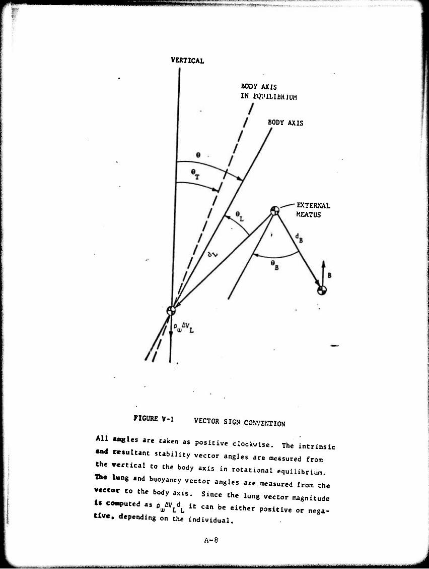
',., ■'I1 ! I I I I "l-IHMII
VERTICAL
BODY AXIS
IN EgUILlBRJUH
BODY AXIS
EXTERNAL MEATUS
FIGURE V-l VECTOR SIGN COWEKTION
All «ogles are taken as positive clockwise. The intrinsic
«ad resultant stability vector angles are measured from
the vertical to the body axis in rotational equilibrium.
The lung and buoyancy vector angles are measured from the
vector to the body axis. Since the lung vector magnitude
ig computed as p ^V d it can be either positive or nega-
tlve, depending on the individual.
A-8
^^^ - ■- - - - - - MMMUMM ^^M^^M^MM
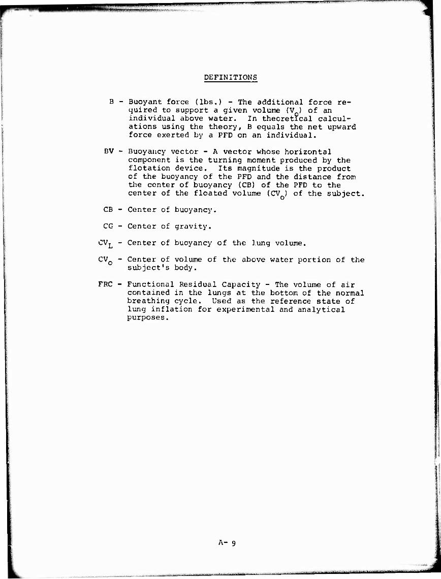
-■■!■■ ■ ' "■
DEFINITIONS
B - Buoyant force (lbs.) - The additional force re- quired to support a given volume (V ) of an individual above water. In theoretical calcul- ations using the theory, B equals the net upward force exerted by a PFD on an individual.
BV - Buoyancy vector - A vector whose horizontal component is the turning moment produced by the flotation device. Its magnitude is the product of the buoyancy of the PFD and the distance from the center of buoyancy (CB) of the PFD to the center of the floated volume (CV ) of the subject.
CB - Center of buoyancy.
CG
CVT
Center of gravity.
Center of buoyancy of the lung volume.
CV0 - Center of volume of the above water portion of the subject's body.
FRC - Functional Residual Capacity - The volume of air contained in the lungs at the bottom of the normal breathing cycle. Used as the reference state of lung inflation for experimental and analytical purposes.
A- 9
-■' ■

'tgiiiifiämmmmi' •<*:—.**,. .'lm«~fmmmM t niiinwiwin im iiiniimii.WMHiM ii —r—i mm .n • ttmmn^^
f
ISV - Intrinsic Stiffness Vector - A vector whose magnitude is the product of the subject's weight (W) and the distance between the sub- ject's CG and CB when fully submorged with the lungs inflated to provide zero net buoyancy. The vector angle is measured between this line and the vertical. The horizontal component of this vector is the moment that would act on the subject without a PFD.when he is at any given angle under the condition zero net buoyancy.
LV - Lung vector - A vector whose horizontal component is the turning moment produced by a change in lung volume AV from the condition of zero net buoyancy to the condition under consideration. The magnitude of LV is the product of the loss In buoyancy due to^Vj and the distance be- tween the centers of the lung volume and floated volume. The vector angle is measured between the line joining those centers of volume and the ver- tical.
NSV - Net Stiffness Vector - The vector sum of the ISV and LV.
PFD - Personal Flotation Device.
J^v - Density of water. Assumed to be a constant 62.4 Ibs./cu.ft.
RSV - Resultant Stiffness Vector - The sum of the NSV and BV.
SSN - Suprasternal notch.
VT _ Subject's total volume including lungs when lungs are inflated so tnat^Py^Vj = w.
W - Height of an individual in air.
e " Equilibium Flotation Angle. Same as anale of Resultant Stiffness Vector. It is the angle measured in the right profile view of the body from the vertical to the body axis when the body is in rotational equilibrium. Angles measured clockwise from vertical are positive. Also referred to as angle of repose and as equilibrium angle.
A-10
i.ll^.i-! ■-■■■■ II* fl ■ » ■■■ll1lMfc— ■! h I ■ ■- . ■ ■ ■■-■ ---^.■- -^. fäUag ....■_

•" tirmf-'-'
m^^r^m^tmm mim^*^^^*^*^
APPENDIX D
EXAMPLE OF DETERMINING THE0RE7ICAL EQUILIBRIUM FLOTATION ANGLE (I.E. THE ANGLE OF THE RSV)
USING SUBJECT NO. 1A, (BEFORE BREAKFAST TEST SESSION), HEAD FORWARD, IN DESIGN NO. 3 PFD
Use computer program CB2 for determining buoyancy and x, y coordinates from lowermost, outermost point on PFD as worn on torso.
A. Data input into computer (inches and degree):
WX)=Wr OF DRY SAMPLE DEVICE HVT=HOR DIST FR FRONT OF VEST TO FRONT OF TORSO WTdVERT DIST FR BOTTOM OF TORSO TO BOITCM OF VEST H&=HOR DIST FR FRONT OF VEST TO SYSTEM CG VSI=VERT DIST FR BOTTOM OF TORSO TO CG OF SYSTEM BVIfcBUOYANCY OF TOTALLY SUBMERGED DEVICE WTll=Wr OF TORSO FRAME PARTIALLY EMERGED ALPHA=ANGLE FR PDRIZ OF TORSO W/PARTIALLY EMERGED PFD W1=WT AT TORSO FRONT TO GIVE ALPHA W2=WT AT TORSO ARM TO GIVE ALPHA VWP=EST. VERT DIST FR TORSO BOT TO CG OF ABOVE-WATER TORSO HWT^EST HOR DIST FR TORSO FRONT TO CG OF ABOVE-WATE:R TORSO Lll=HOR DIST FR TORSO FRONT TO LOWEST POINT OF BACK
FLOTATION MAT'L—IF NO MAT'L ON BACK, SET LlUWTr=0 VVTT=VERT DIST FR TORSO BOT TO LOWEST POINT OF BACK
2.95 4.75 0 9.6 10.4 35.18 4.7
51 8.28 4.03
11 13
B. Computer results:
EFFECTIVE BUOYANCY OF PFD (LBS) = 17.01 (48.4% OF FULL VALUE) HOR DIST FRO FRONT OF PFD TO CB = 8.57 VERT DIST FRO BOTTOM OF PFD TO CB = 5.83 HOR DIST, IN., FR FRONT OF DEVICE TO DEVICE CG = 9.51 VERT DIST FR BOTTOM OF DEVICE TO DEVICE CG = 9.0 8
II. Use computer program LLBV to compute the buoyancy vector. This program is needed to relate the coordinate system in Step I above, to the subject's body; i.e., the distance from the CP to the center of the floated volume,assumed to be at the external meatus.
B-l
ugammttmmtmmmm^mmtmmM
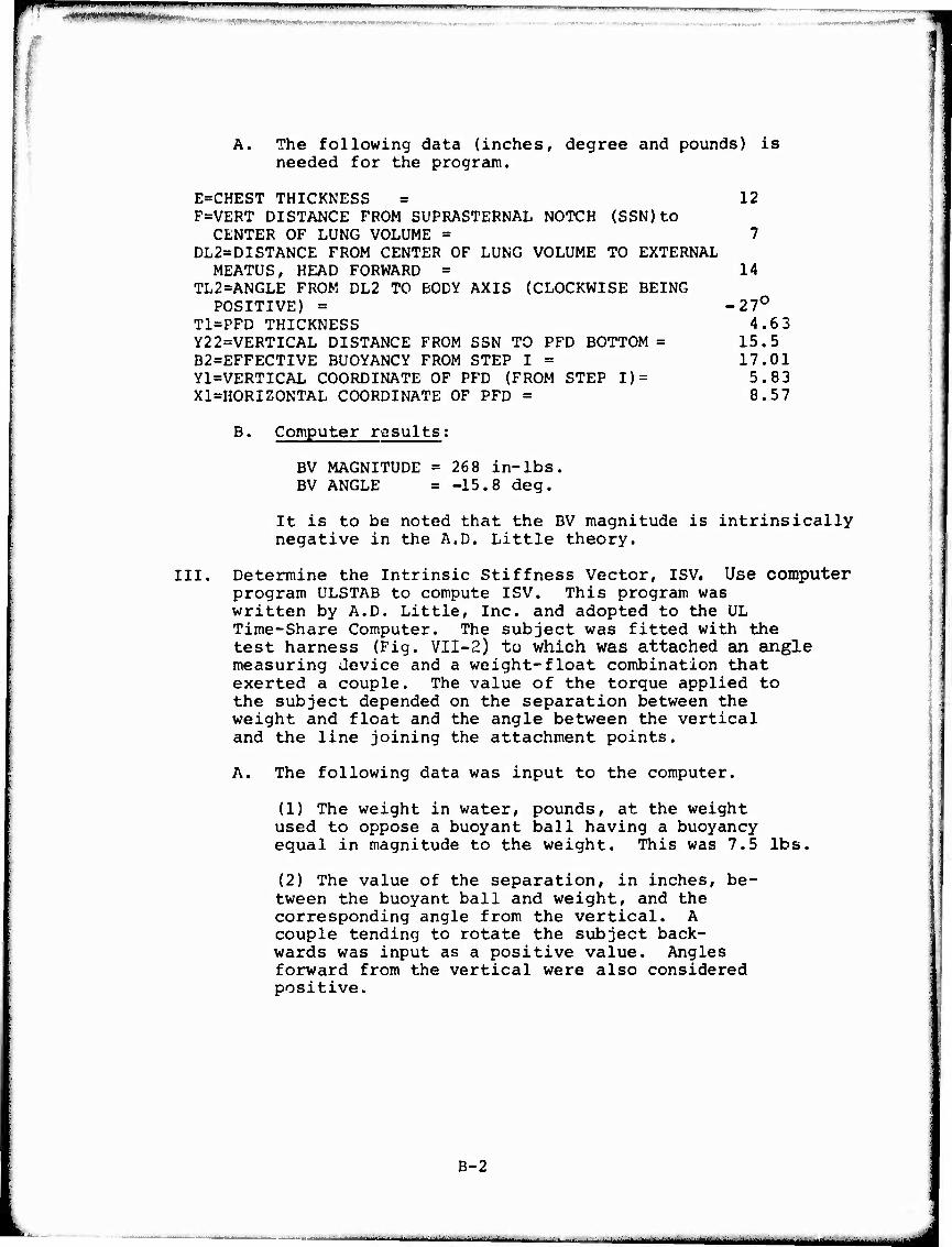
■■wwi.w« — - ■ -—
'-,- WMFmW!i''"'**W>i<t*
14
-27° 4.63
15.5 17.01 5.83 8.57
A. The following data (inches, degree and pounds) is needed for the program.
E=CHEST THICKNESS = 12 F=VERT DISTANCE FROM SUPRASTERNAL NOTCH (SSN)tO CENTER OF LUNG VOLUME = 7
DL2=DISTANCE FROM CENTER OF LUNG VOLUME TO EXTERNAL MEATUS, HEAD FORWARD =
TL2=ANGLE FROM DL2 TO BODY AXIS (CLOCKWISE BEING POSITIVE) =
T1=PFD THICKNESS Y22=VERTICAL DISTANCE FROM SSN TO PFD BOTTOM = B2=EFFECTIVE BUOYANCY FROM STEP I = Y1=VERTICAL COORDINATE OF PFD (FROM STEP I) = Xl=HORIZONTAL COORDINATE OF PFD =
B. Computer results;
BV MAGNITUDE =268 in-lbs. BV ANGLE = -15.8 deg.
It is to be noted that the BV magnitude is intrinsically negative in the A.D. Little theory.
III. Determine the Intrinsic Stiffness Vector, ISV. Use computer program ULSTAB to compute ISV. This program was written by A.D. Little, Inc. and adopted to the UL Time-Share Computer. The subject was fitted with the test harness (Fig. VII-2) to which was attached an angle measuring device and a weight-float combination that exerted a couple. The value of the torque applied to the subject depended on the separation between the weight and float and the angle between the vertical and the line joining the attachment points.
A. The following data was input to the computer.
(1) The weight in water, pounds, at the weight used to oppose a buoyant ball having a buoyancy equal in magnitude to the weight. This was 7.5 lbs.
(2) The value of the separation, in inches, be- tween the buoyant ball and weight, and the corresponding angle from the vertical. A couple tending to rotate the subject back- wards was input as a positive value. Angles forward from the vertical were also considered positive.
B-2
■ I ■f.a—M—IMM
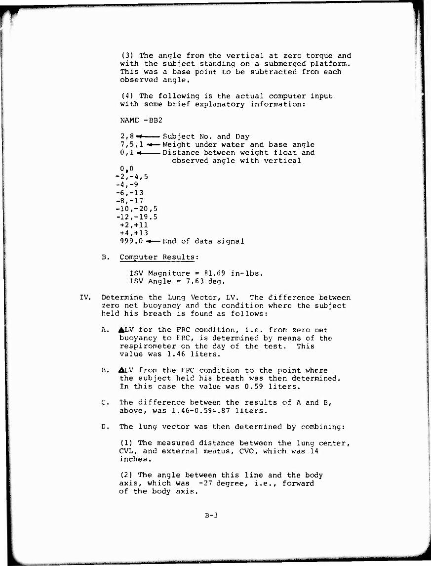
(3) The angle from the vertical at zero torque and with the subject standing on a submerged platform. This was a base point to be subtracted from each observed angle.
(4) The following is the actual computer input with some brief explanatory information:
IV.
NAME -BB2
2,8-« 7,5,1 -«— n i -*
0,0 2,-4,5 4,-9 6,-13 8,-17 10,-20,5 12,-19.5 +2,+11 +4,+ 13 999.0 -•—
Subject No. and Day Weight under water and base angle Distance between weight float and
observed angle with vertical
End of data signal
B. Computer Results;
ISV Magniture = 81.69 in-lbs. ISV Angle = 7.6 3 deg.
Determine the Lung Vector, LV. The difference between zero net buoyancy and the condition where the subject held his breath is found as follows:
A. ALV for the FRC condition, i.e. from zero net buoyancy to FRC, is determined by means of the respirometer on the day of the test. This value was 1.46 liters.
B. ALV fron the FRC condition to the point where the subject held his breath was then determined. In this case the value was 0.59 liters.
C. The difference between the results of A and B, above, was 1.46-0.59=.87 liters.
D. The lung vector was then determined by combining:
(1) The measured distance between the lung center, CVL, and external meatus, CVO, which was 14 inches.
(2) The angle between this line and the body axis, which was -27 degree, i.e., forward of the body axis.
B-3
■MBMH MM
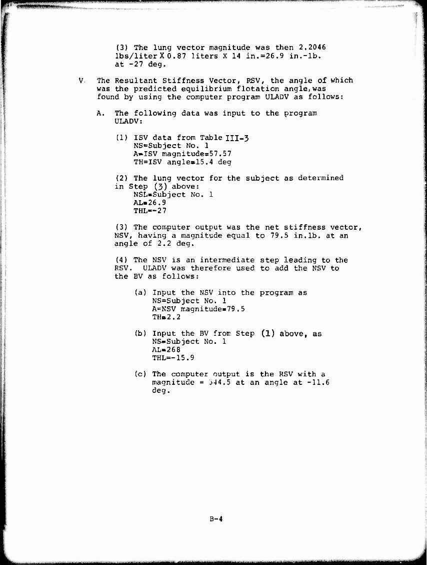
^Bapww^^^^»piiiii i " im^w^^»" ' i- ■....»!.. .....^ — — -—---■'~ „^™™^_— "'iT-. ■^^- ■>■
iniMH^mmniijiiwi«.»,.-, .«w»»««»
(3) The lung vector magnitude was then 2.2046 lbs/liter X 0.87 liters X 14 in.=26.9 in.-lb. at -27 deg.
The Resultant Stiffness Vector, RSV, the angle of which was the predicted equilibrium flotation angle)was found by using the computer program ULADV as follows:
A. The following data was input to the program ULADV:
(1) ISV data from Table III-3 NS=Subject No. 1 A-ISV magnitudes57.57 TH=ISV angle»15.4 deg
(2) The lung vector for the subject as determined in Step (3) above:
NSL-Subject No. 1 AL-26.9 THL—27
(3) The computer output was the net stiffness vector, NSV, having a magnitude equal to 79.5 in.lb. at an angle of 2.2 deg.
(4) The NSV is an intermediate step leading to the RSV. ULADV was therefore used to add the NSV to the BV as follows:
(a) Input the NSV into the program as NS=Subject No. 1 A=NSV magnitude»79.5 TH»2.2
(b) Input the BV from Step (1) above, as NS-Subject No. 1 AL-268 THL=-15.9
(c) The computer output is the RSV with a magnitude = J-H.5 at an angle at -11.6 deg.
B-4
^^^m^m^^mm^mm^tmatmmmtmmmm^i^m^^t^^^^^m^mmtm^mammmmmtmammmmmmiimmam

■■■WMOTBVnMmVHB^^^'^"'^ ' ■ ■■ -— ■■ ■■-
APPENDIX C
Computer Programs and Subroutines
Listings of the following computer programs and sub-
routines used in the investigation are given in this Appendix;
1. CD of Partially Emerged PFD
2. Subroutine CGPFD
3. -Subroutine CG.MOVE
4. UL3V
5. ULSTA3
6. ULADV
Documentation is also given for the first three items
above. The programs UL3V and ULSTAB are identical to those used
in the investigation reported in Reference 1 and documentation
is not repeated here. ULBV determines the magnitude and phase
angle of the buoyancy vector from measurements of individual
subjects and PFD's, ULSTAB computes the equilibrium flotation
angle for a subject wearing a PFD, given the magnitudes and phase
angles of the intrinsic stiffness vector # lung vector, anc'
buoyancy vector.
The last program, ULADV, merely adds vectors in polar
form.
C-l
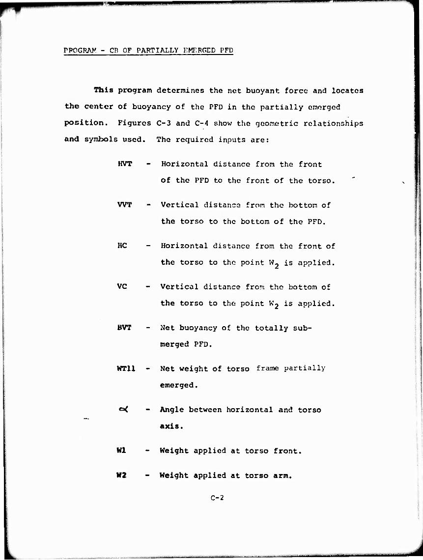
PPOGRAy - CH OF PARTIALLY KMERGED PFD
This program determines the net buoyant force and locates
the center of buoyancy of the PFD in the partially emerged
position. Figures C-3 and C-4 show the geometric relationships
and symbols used. The required inputs are:
HVT - Horizontal distance from the front
of the PFD to the front of the torso.
WT - Vertical distancs fron the bottom of
the torso to the bottom of the PFD.
HC - Horizontal distance from the front of
the torso to tho point W2 is applied.
VC - Vertical distance from the bottom of
the torso to the point Kj is applied.
BVT - Net buoyancy of the totally sub-
merged PFD.
WT11 - Net weight of torso frame partially
emerged.
c< - Angle between horizontal and torso
axis.
Wl - Weight applied at torso front.
W2 - Weight applied at torso arm.
C-2
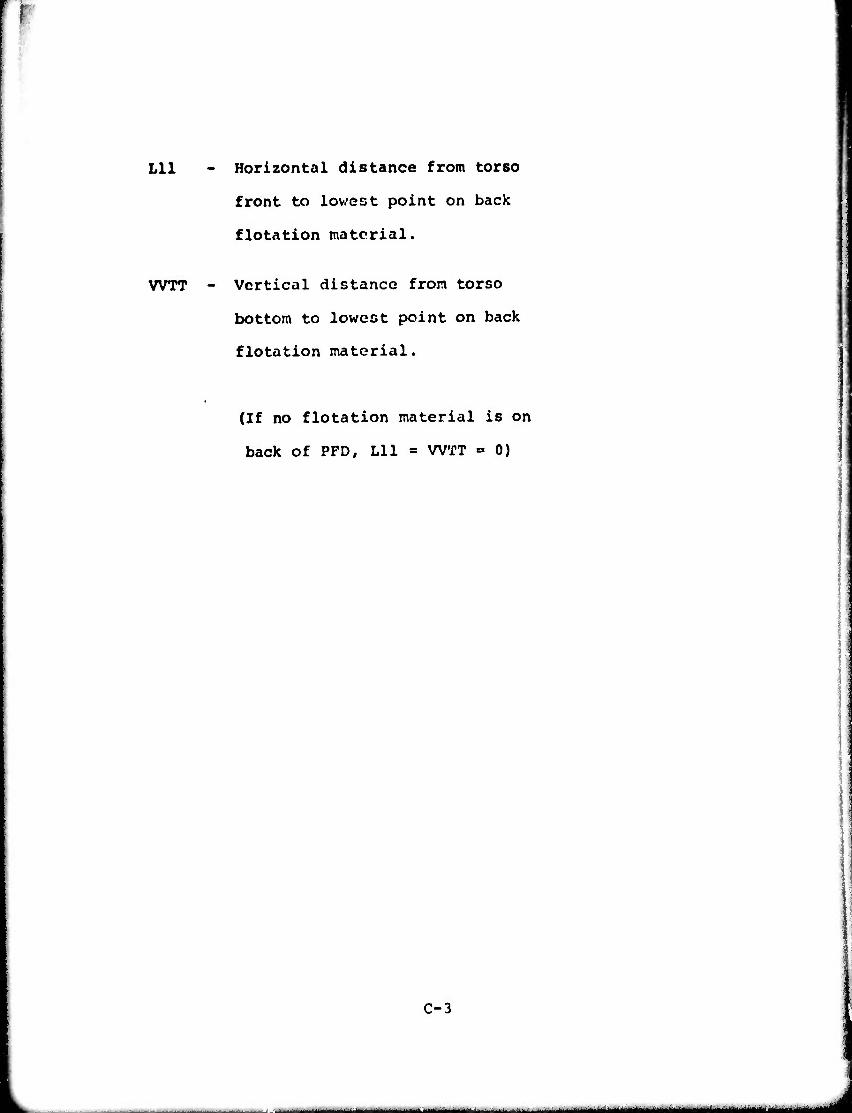
Lll Horizontal distance from torso
front to lowest point on back
flotation material.
WTT - Vertical distance from torso
bottom to lowest point on back
flotation material.
(If no flotation material is on
back of PFD, Lll = WTT = 0)
C-3
- - - - —--
■
wmm mmmmm*wn i i
■/!*»"«•»■ . ■-
By force balance, the net buoyancy is:
BS = WT11 + Wl + W2
The following series of calculation determines the hori-
zontal distance of the CB frorr; the front of the PFD (HCBS)
and the vertical distance of the CB from the bottom of the
device, (VD1), Subroutines CGMOVE and CGPFD are called during
the computation.
First the location of the vertical line throuch the CB is
found by computing moments about the point 0 in Fig. C-3, the
point at which force W- is applied.
HI = (HC) sin^
H2 = (VC) coso<
L « (HT11) sin'*' +(VT11) cos^X
where HT11 and VT11 are obtained from Subroutine CGMOVE.
C «= Hi + H2 - L
The horizontal distance AB from point 0 to the vertical line
through CB is now obtained by setting the sum of the moments about
point 0 equal to zero.
C-4
—--" * -■< ii mm
mumm "' ' ,,-•. ... i - minfiii'*ti'tmAff*>'*<
AB - (WT11) (C) +(W1)(H1 + H2) /BS
BC = Hl + ■ i' -AB
Ll » (BC)/Sinc<
The following steps determine the upper and lower limits,
within which CB must fall. The upper limit is simply the level
of the CG of the dry device, located by the coordinate CBl in
Fig. C-4. If ^ = 0, CBl is given by
CBl « HVT - HD
where HD is obtained from Subroutine CGPFD. In this case,
VBOT « 0.
When «< is not zero, the following system of calculations
is used to find CBl.
VS2 « VD + WT
where VD is obtained from Subroutine CGPFD.
HT- «HD - HVT 4
HSH «= (VS2)/sin*<
A « (Ll) tano<- VS2
B - (HT4)/tano<
C-5
-'' tmmamm - .... ....l]Wltlttit mmüammmmmmtm i^MMMMMMM
Depending on the value of «x , the distance A may be
negative, zero, or positive. Fig. C-4 depicts the situation
for positive A, for which
VI - (A + B) sinö<
This also applies when A « 0. For negative values of A, the
situation depicted In Fig. C-5 exists. In that case,
C » j A/tan (X (
VI B (HT4 + C) cos o<
Calculations are now made to locate the lowest portion
of the PFD, which is the lower limit of CB. For material on
the front of the PFD
V2 ■ (LI) cos**
VBOT = V2 + (WT) sin«*
For material on the back of the PFD,
LB » Lll - LI
VW ■ (LB)/tan OK
VB0T1 « (WTT - VW) sino<
C-6
■■ ■ ■■ ■ ■■■■■ " -- --■ --■ ■ ■ ■ ■in m hm^^^tmätmmmit^mma^m^^^lim^mtm

If VB0T1 < VBOT, it is substituted for VBOT in the re-
mainder of the computations. Otherwise VBOT for the front
material is used. When there is no back material on the PFD,
the computation of VB0T1 is omitted. This command is given in
the program by setting Lll equal to zero in the input data.
The value of CBl is now calculated. When A is negative,
CB1 = HSH - VI - VBOT
and when A is zero or positive,
CBl »= (LI)/cos - VI - VBOT
The quantities VBOT and CBl locate the lower and upper
limits of CB, and it remains to determine CBSHIF by the
approximate procedure described in Section II and Fig. 2.
Figure C-2A depicts the proportioning relationship graphically,
and the appropriate algebraic expression is —
CBSHIF s MLU^l + CBl + VBOT _ (CBl) (BVT) (WDD + BVT) (WDD + BVT)
C-7
^— 1.iiii.<iir ii>f..«iiiii. |||||tM||iMgi|MMM||MMMM|,|M<|^^
W»<WW>WI)IM|WI>l|Wmi[||iilWM»ii»ii " WWW—WWW— WW—WW
It follows then that whenc^ / 0.
HCBS = HVT + LI - (CBSHIF) COS «J
and
VDl " (CBSHIF) sino< - WT
For the case o< » 0 however,
HCBS = HVT - CBSHIF
VDl = VD
Thus the magnitude of the net buoyant force BS and coordinates
(HCBS, VDl) of the center of buoyancy of the partially energed
device have been determined.
C-8
-■•——- - —— ■ -- — —— --- mmjigm. MM«.«

^M wim"*
Subroutine CGPFD
This subroutine calculates the location of the center
of gravity of the PFD from the coordinates of the CG's of
the torso alone and of the torso-PFD system. Fig. C-6 shows
the geometric relationships and symbols uced. Required
inputs are:
HT1 - Horizontal distance from the front
of the torso frame to its CG.
HVT Horizontal distance from the front
of the torso to the front of the
PFD.
HS Horizontal distance from the front
of the PFD to the CG of the torso-
PFD system.
VT Vertical distance fron the bottom
of the torso to its CG.
WT - Vertical distance from the bottom
of the torso front to the bottom
of the PFD front.
VS1 Vertical distance from the bottom
of the torso to the CG of the
torso-PFD system.
C-y
..MMMa^ua^M, I^MHMa MMMIMMMMHHMiaiJHMal
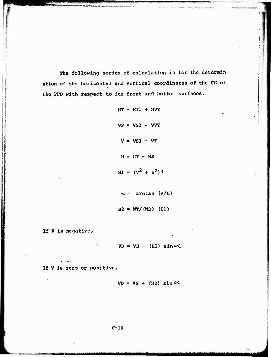
" ■"■ mi ' ■l, l,*l,l, "•I"
$.*K*ftm'-'*mp*>uH*'Bim'w wwttimM* nrinniwmmpijiiiuNiaMMiMii wm Mt« ,
!l
The following series of calculation is for the determin-
ation of the horizontal and vertical coordinates of the CG of
the PFD with respect to its front and bottom surfaces.
HT » HT1 + HVT
i
If V is negative.
VS = VS1 - WT
V » VS1 - VT
H = HT - HS
HI = (V2 + K2)^
o; ' arc tan (V/H)
H2 » WT/(V7D) (HI)
VD » VS - (H2) sin«^.
If V is zero or positive.
VD « VS + (H2) sin^X
C-10
'« ■■HI. ■ IIIIIMII i B m^^aBMaaa^,,,,^,,^^ ■HMMMBU

mmimmi« i . i •■ ■ " <" ' " »m
If H is negative,
HD = HS + (112) cos o<
If H is xero or positive,
HD = HS - (152) corw
Thus, HD and VD, the desired coordinates, arc determined.
C-ll
—i— 1 —i—mugK^jn

'•> »■inn
Subroutine - CGMOVE
This subroutine computes the coordinates (HT11 and VT11)
of the effective center of gravity and the net weight
(WTUNDR ♦ ABVWTR) of the partially submerged torso. Figure C-l
shows the geometric relationships and symbols used. Required
irputs are:
HT1 - Horizontal coordinate of the true
CG of the torso
VT - Vertical coordinate of the true
CG of the torso
HWT - Estimated distance from torso front
to the CG of the above-water torso
VWT - Estimated distance from the torso
bottom to the CG of the above-water
torso
WT - Weight of torso frame in air
__ WT11 - Net weight of torso frame partially
submerged
MTS - Net weight of torso frame fully
subme-ged
WT - Distance from bottom of torso to
bottom of PFD
C-12
■- — umliiiillM— " I MMMMM ■MM^HMMMMMHUaBBaMi
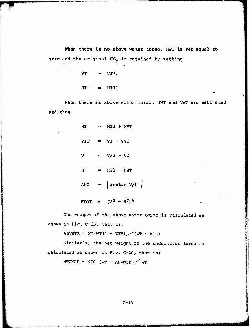
When there i.s no above water torso, HWT Is set equal to
zero and the original CG is retained by setting
VT = VPll
IIT1 = HT11
When there is above water torso, UWT and VWT are estimated
and then
HT = HT1 + HVT
VTT = VT - WT
V «= VWT - VT
H »= HT1 - HWT
ANG = jarctan V/H |
HTOT - (V2 + H2)1*
The weight of the above water torso is calculated as
shown in Fig. C-2B, that is:
ABVWTR = WT(WT11 - WTS)^^(WT - WTS)
Similarly, the net weight of the underwater torso is
calculated as shown in Fig. C-2C, that is:
WTUNDR = WTS (WT - ABVWTR)^ WT
C-13
l i ■mii-MlftMif nniii —- -- I ■■-■-^'—^—^^^^^

Since the sum of the moments about the new CG is zero,
(HI) (WTUNDR) = (HTOT - HI) (MJVWTR) or
(HI) :-- (HTOT) (ABWTR)/(WTUNDER + ABVWTR)
If H is negative,
HT11 = HT1 + (HI) Cos (ANG)
If H is positive or zero,
HT11 = HT1 - (HI) Cos (ANG)
If V is negative,
VT11 = VT - (HI) Sin (ANG)
If V is positive or zero,
VT11 = VT + (HI) Sin (ANG)
Thus, the CG and downward force associated with the
partially submerged torso have been determined.
C-14
" ■-' -■—■^^--- ■- ....^-».. M^HMliMiHWMHMIaiiiaMMMIMaHBilMril

^^^^^wmmm ■-.i.i ■"■
WWIWW.»PW«IIIHWWWIIWI»I>II'«I»»','>»W"'''--'''T-'' •*■<•<■*•
V
w" A>
-; [ V^ ^ ^ÖVKTK
^nfc i t .M ^r^ «<*
_l ZJ i •_
^ A
V
S
-— .. . ■
r
\
^
r<
J-J
^v^. ^
^
FIGURE C-l
CG AS AFFECTED BY ABOVE-WATER TORSO
C-15
- ■ —
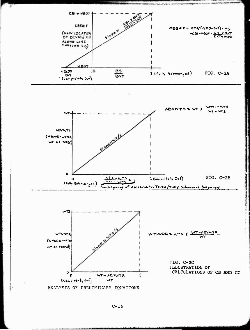
•.t»flWifHPWT*Ttti»^*'M-r'«ir^i!.J^>»«wi««^'1 TO^jw^.^r-Hw-r-ijipniW-*«"^ '
CBSHIPe CtMAvvDD-»BvT)K (35
1 (Polly VjW«»,«ra«i) FIG. C-2A
vvr _
ABVWTU
ABVWTR ■=■ wr X WT - *TS
l(c.-,ple+.iy 0^) FIG. C-2B
^-^öv^y^nty «f Abov#.W4k+trTor«o/fully 5t;km«rj«JAu«yan<y
v-'T — wr«
VA/T5
0 WT- ^ftW/Tf^ WT
ANALYSIS OF PRELIMINARY EQUATIONS
C-16
WTUN'OR-a- WTS X
FIG. C-2C ILLUSTRATION OF CALCULATIONS OF CB AND CG
^<<aMMM^^,^MMitlMMMtMIMMj—j« -n

BUOYANT DEVICE
FIGURE C-3
SCHEMATIC OF PFD - TORSO FRAME SYSTEM
C-17
■-—"■^■^■'^■■^'- ^ ^^^^MM^MMMMMI
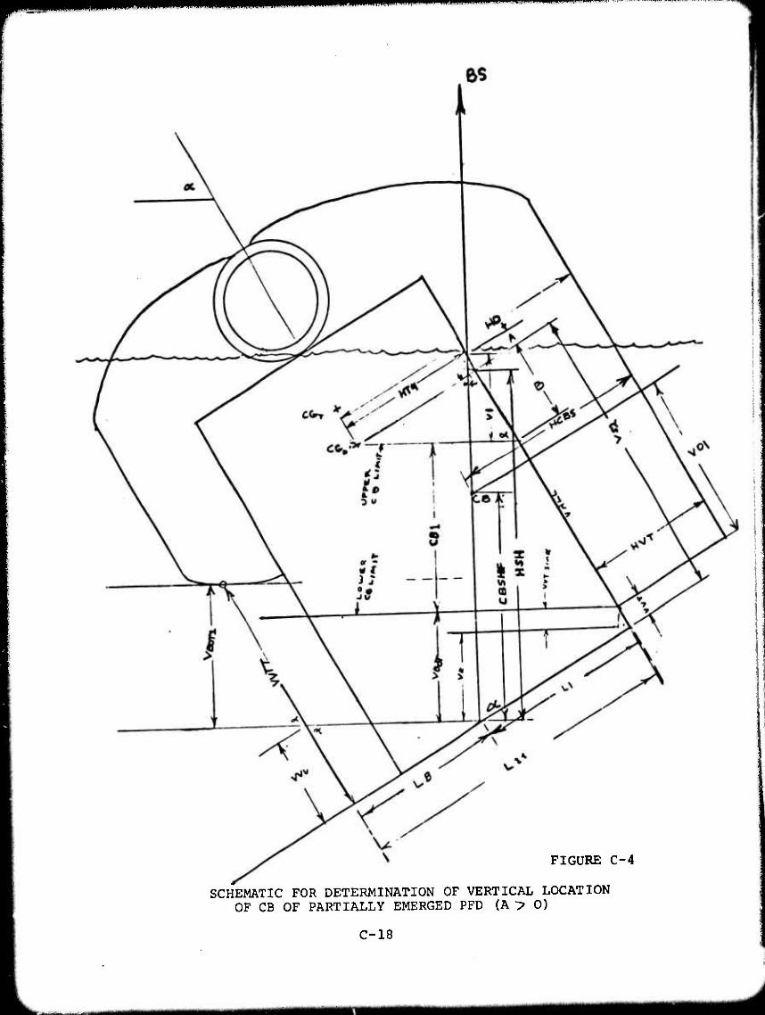
FIGURE C-4
SCHEMATIC FOR DETERMINATION OF VERTICAL LOCATION OF CB OF PARTIALLY EMERGED PFD (A > 0)
C-18
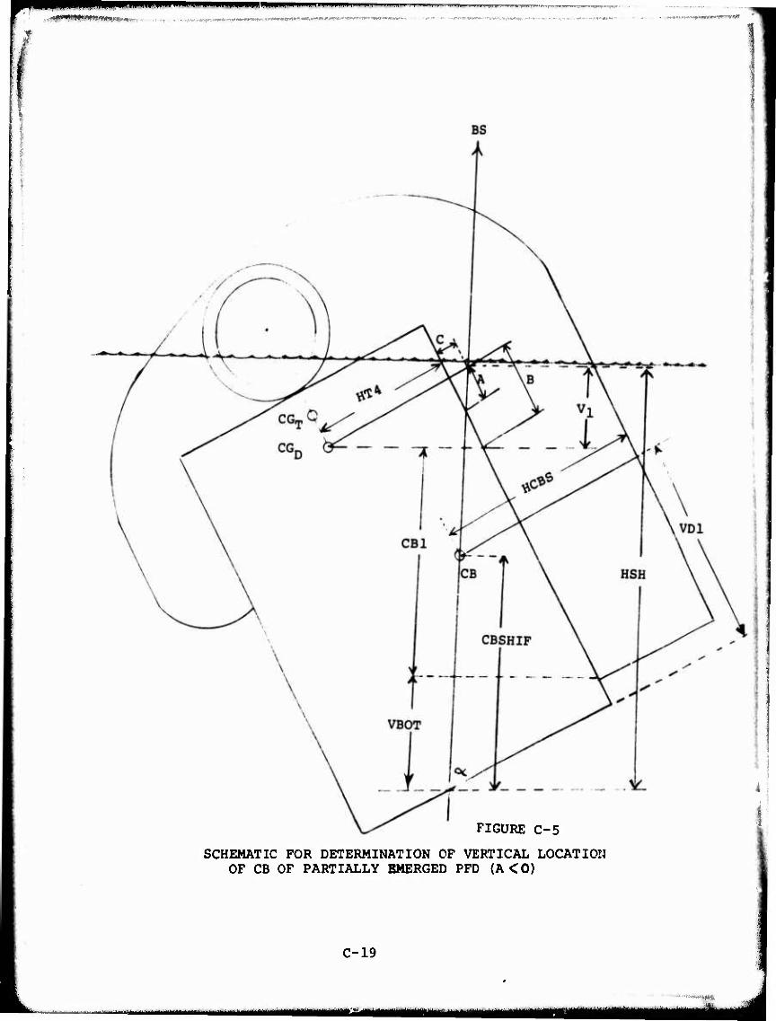
mmmmm^m ' . ^- ■ ■-■■ ■■—-— -—.—.
■
FIGURE C-5
SCHEMATIC FOR DETERMINATION OF VERTICAL LOCATION OF CB OF PARTIALLY EMERGED PFD (A<0)
C-19
MBBMH tt^MMMB
■ ■•--»«*»

—■'■'•—'-"»-' m M
FIGURE C-6
SCHEMATIC FOR DETERMINING CG OF BUOYANT DEVICE
C-20
-in-' - —.^-—^—~-^~ ^^aammim^tmmmm ^^MMMMMMMMH _J

The following pages contain the computer program listings in FORTRAN IV.
ILCB
• •••••CB OF PARTIALLY EMERGED PFD**H.R.SUCHOHIL-10/9/73 ALL 01 STANCE IN INCHES/ VTS IN LBS« AND ANGLES IN DE6 HTI-HOR DIST FR FRONT OF TORSO TO TORSO CG VT-VERT DIST FR BOTTOM OF TORSO TO TORSO CG VT-VT OF TORSO FRAME VDO-VT OF DRY SAMPLE DEVICE
HVT-HOR DIST FR FRONT OF VEST TO FRONT OF TORSO WT-VERT DMT FR BOTTOM OF TORSO TO BOTTOM OF VEST HC-HOR DIST FR FRONT OF TORSO TO PT OF W2 ATTACHMENT VC-VEBT DIST FR BOTTOM OF TORSO TO PT OF «2 ATTACHMENT HS-HOR DIST FR FRONT OF VEST TO SYSTEM CG VSI-VERT DIST FR BOTTOM OF TORSO TO CG OF SYSTEM BVT-BUOYANCY OF TOTALLY SUBMERGED DEVICE VT11-VT OF TORSO FRAME PARTIALLY EMERGED VTS-VT OF TORSO FULLY SUBMERGED ALPHA-ANGLE FR HORIZ TO TORSO AXIS (90-OBS ANGLE OF SUBJ) VI-VT AT TORSO FRONT TO GIVE ALPHA W2-WT AT TORSO ARM TO GIVE ALPHA VWT-EST. VERT DIST FR TORSO BOT TO CG OF ABOVE-VATER TORSO HVT-EST HOR DIST FR TORSO FRONT TO CG OF ABOVE-VATER TORSO
Lll-HOR DIST FR TORSO FRONT TO LOWEST POINT OF BACK FLOTATION MAT «L—IF NO MAT *L ON BACK« SET L114WTT - 0
WTT-VERT DIST FR TORSO BOT TO LOWEST POINT OF BACK TO OMIT PRINTING CG COORDINATES* ENTER % I • AT END OF DATA
REAL L/LULL C0MMONHT11 / VT11« VD«HD/VS
•TEMPORARILY TO AVOID INSERTING REPETITIVE DATA* DATAHTl/4.9/,VT/ll.l5/,WT/5.l9/*HC/7.l//VC/I4.8//WTS/4.3/ 888C0NTINUE N-0 READ«VDD*HVT*WT*HS*VS1«RVTJVT11«
«ALPHA« VI * VS, WT* H WT, LII« VVTT« N V-VT11 BS«VTll<*-VltV2 CALLCGM0VE<HTUHVT«VT/WT,WTI1,VWT,HWT/WTS,WT)
•SUBPROG FOR CALCULATING RESULTANT CG OF ABOVE-«BELOW-VATER •TORSO« IE SOLVES FOR HT1 i« VT1 l/HOR«VutT COORDINATES
ALPHA-ALPHA/57. 2957 SINA"SIN(ALP>IA> COSA-COS(ALPHA) TANA-TAN (ALPHA) Hl-HC^SINA H2-VC#COS( ALPHA) L-(HT114-VT11/TANA)^SINA C-HI-fH2-L AB-(W»C*VI»(H1+H2))/BS BC«H1«-H2-AB LI-BC/SIHA CALL CGPFD(HT1,HVT* VS1»WT#VT«MS« VT« VDD)
C-21
mmmmtmmmm
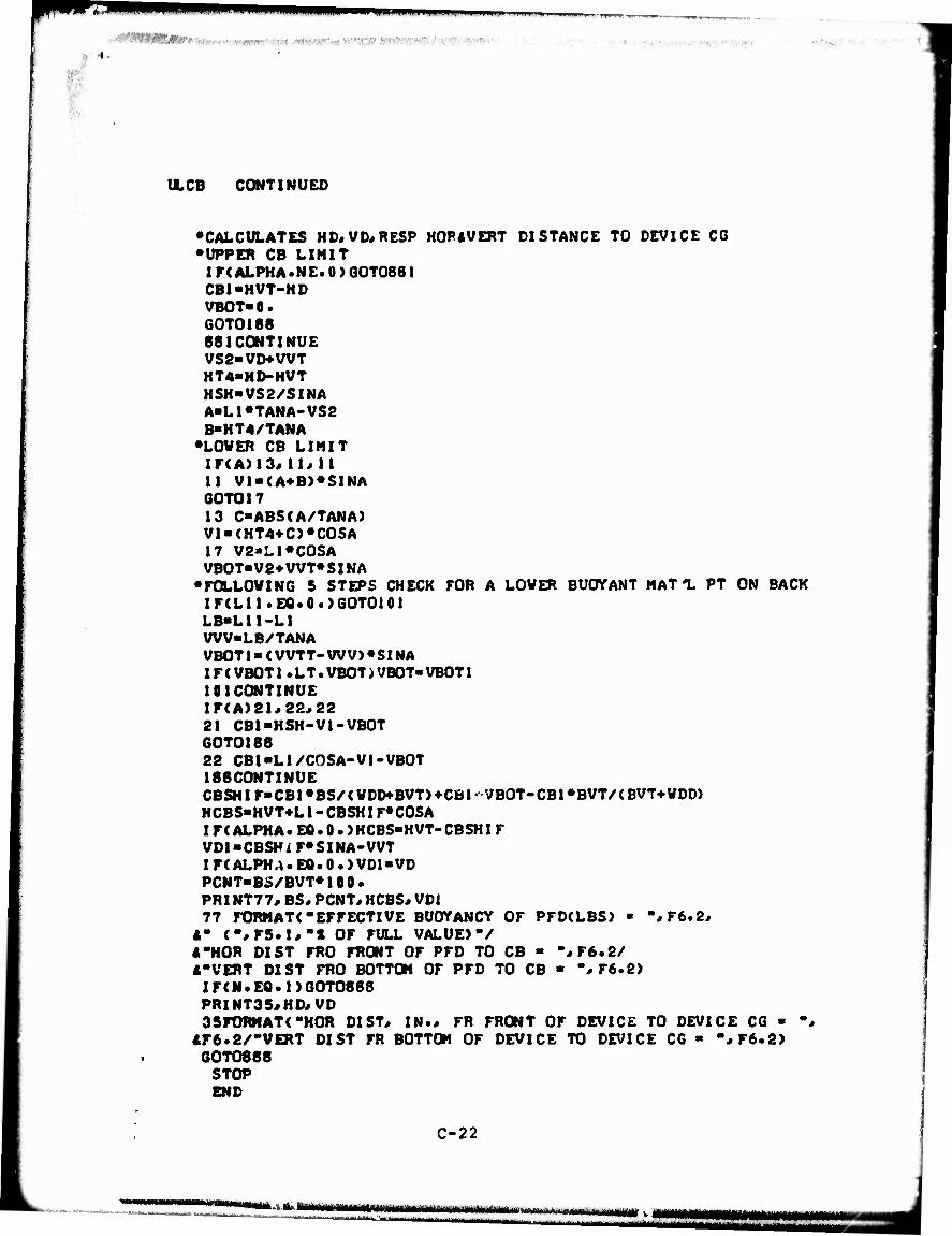
•
,.,,,,.• ■■ ' ■ ^
XCB CONTINUED
•CALCULATES HD«VD#RESP HOPAVERT DISTANCE TO DEVICE CG •UPPER CB LIMIT
IF<ALPHA.NE.0 > QOT0881 CB1-HVT-HD VBOT«0. GOTO188 881CQNTINUE VS2»VD*WT HT4-HD-HVT HSH-VS2/SINA A-L!«TANA-VS2 B>HT4/TANA •LOVER CB LIMIT IF(A)13«11«11 11 V1-<A*B>^SINA GOTO17 13 C"ABS(A/TANA) Vl-<HT4+C)^COSA 17 V2»Ll^COSA VB0T»V2*WT^SINA
•FOLLOWING 5 STEPS CHECK FOR A LOVER BUOnTANT MAT'L PT ON BACK IF<Lll.EQ.0.)GOTO101 LB-L11-L1 WV-LB/TANA VB0T1»<VVTT-WV>^SINA IF(VBOTl .LT.VBOT)VBOT-VBOT1 111CONTINUE IF(A>21«22#22 21 CBl-HSH-Vl-VBOT 60T0188 22 CB1-L1/COSA-V1-VBOT 188CONTINUE CBSHIF»CBl^BS/<VDD»BVT)*CBi- VBOT-CBl^BVT/<BVT*WDD> HCBS«HVT-i-Ll-CBSHIF«COSA I F( ALPHA. Efi• 0 • )HCBS-HVT-CBSHI F VDl»CBSHi F^SINA-VVT IF(ALPHA.EQ.0.}VD1«VD PCNT«B5/BVT*I00. PRINT77, BS« PCNT«HCBS« VD1 77 FORMAT<-EFFECTIVE BUOTANCY OF PFDCLBS) » -*F6.2*
4" <-*r5.1#"X OF FULL VALUE)-/ 4-HOR DIST FRO FRONT OF PFD TO CB - m»rt,2/ 4-VERT DIST FRO BOTTOM OF PFD TO CB ■ % F6.e) IF<N.EQ.l)GOT0888 PRINT35«HD«VD 3SrORHAT(-HOR DIST« IN., FR FRONT OF DEVICE TO DEVICE CG - "J
4F6.2/-VERT DIST FR BOTTOM OF DEVICE TO DEVICE CG ■ -*F6.2) GOT0888 STOP END
C-22
million iin iiiriiiniiniiiinii m<*i. i n., tmmtmmmmltm ■. i

,■•■■■■. ■ ■
ILCB CONTINUED
SUBROUTINECaMOVE<HTI«HVT# VT« VVT« VT11 # VVT/HVT/VTS« VT> CQMHON HTIUVTI!
• CALCULATES APPROX LOCATION OF RESULTANT C6 AS AFFECTED BY CG • OF ANY ABOVE-VATER TORSO(HT1 UVTI 1}
IF(HVT)4«4«5 4VTI1-VT HT11-HT1 RETURN 5HT-HTUHVT VTT-VT-WT V-VVT-VT H-HT1-HVT ANG»ABS(ATAN(V/H)> HTOT-S0RT(V«»2*H»*2)
• THE ABOVE-VATER VT OF TORSO IS« ABVVTR"VT»<VT11-VTS)/<VT-WTS)
• THE UWDERVATER VT OF TORSO IS« VTUNDR»VTS»<VT-ABVVTR)/VT
• FROM VTUNDR«Hl-ABVVTR»(HTOT-Hl)»HTOT«ABVVTR-HI»ABVVTR H1 >HTOT«ABVVTR/( VTUNDR-*-ABVVTR) 65IF(H>20«10« 10 16HT11-HT1-H1«C0S(ANG) GOTO30 20HT1l-HTI+Hl«COS(ANG) 39CONTINUE IF(V)60#40«40 40VTll-VT-»-Hl*SIN(ANG) RETURN 60VTIl»^T-HI»SIN(ANG> RETUK«
•ALLOVING FOR SHIFT DUE END
•
TO ABOVE-VATER TORSO VT ACTING ALONE«
FUNCTION TANCA) TAN-SIN(A)/COS(A) RETURN END
•
SUBROUTINE CGPFD(HTI«HVT«VSI,VVT«VT«HS«VT«VD) • CALCULATES CG OF PFD
COHMONX« Y« V D« H D« V S HT-HTH-HVT VS-VS1-WT V-VSI-VT H-HT-HS HI-S0RT<V»»2+H«»2> AN6-ABS(ATAN<V/H)) H2-VT/VD*H1 IF(V>6«4«4
C-23
"|«'>III IMMUMM
■■■'-■
mttttt ■ - - ■- mmti mm
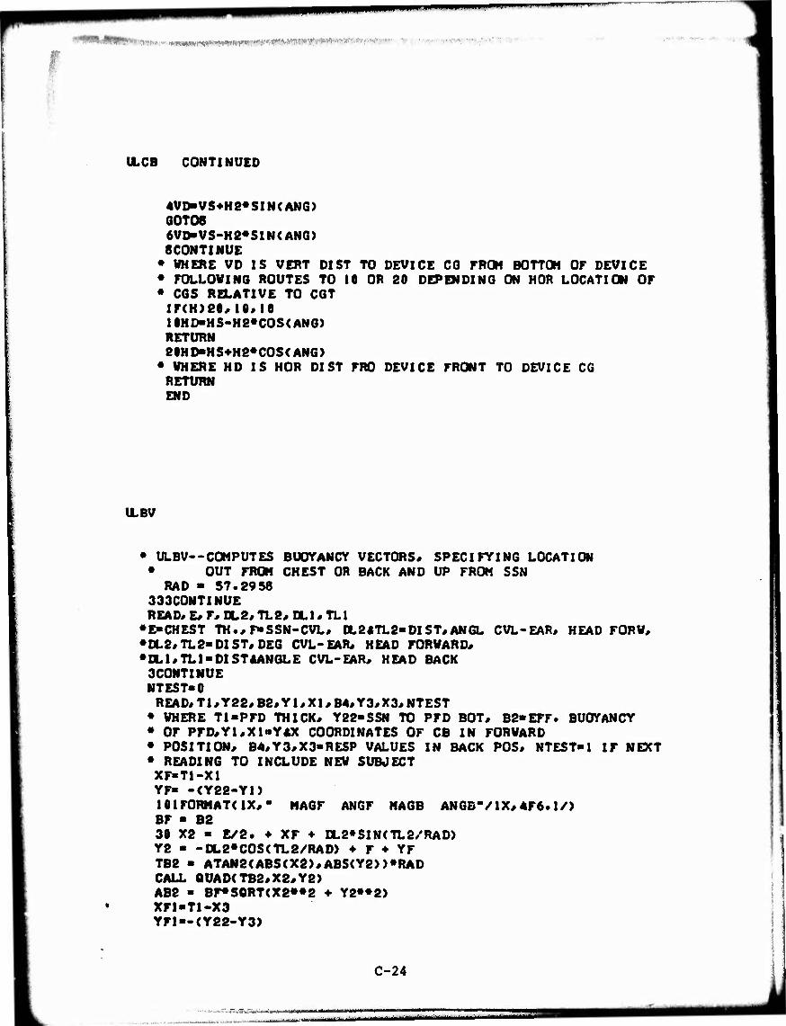
■ vwmm m>^*i*tw^wTWW'f''WiVft ■■■•■.
ILCB CONTINUED
4VD-VS4>H8*SIN(AN6> G0TO8 6VD*VS-H2«SIN(ANG> 8CONTINUE
• WHERE VD IS VERT DIST TO DEVICE CG FROM BOTTOM OF DEVICE • FOLLOWING ROUTES TO 10 OR 20 DEPENDING ON HOR LOCATION OF • CGS RELATIVE TO CGT
IF(H>Se*10*lO 1 IHD-HS-H2*COS< ANG) RETURN e0HD"HS+H8*COS(ANG>
• WHERE HD IS HOR DIST FRO DEVICE FRONT TO DEVICE CG RETURN END
ILBV
• ULBV--COMPUTES BUOYANCY VECTORS« SPECIFYING LOCATION • OUT FROM CHEST OR BACK AND UP FROM SSN
RAD - 57.2958 333CONTINUE READ« E« F« 0L2« TL2« CLI« TLI
•E-CHEST TH.«F*SSN-CVL« 0L2«TL2>DIST«ANGL CVL-EAR« HEAD FORV« •CL2«TL2«DIST« DEC CVL-EAR« HEAD FORWARD« •0L1«TL1"DISTRANGLE CVL-EAR« HEAD BACK
3CONTINUE NTEST-0
READ«T1«Y22«B2«Y1«X1«B4«Y3«X3«NTEST • WHERE TI-PFD THICK« Y22-SSN TO PFD BOT« B2-EFF. BUOTANCY • OF PFD«Y1«X1»YAX COORDINATES OF CB IN FORWARD • POSITION« B4«Y3«X3-RESP VALUES IN BACK POS« KTEST-1 IF NEXT • READING TO INCLUDE NEW SUBJECT XF-TI-X1 YF» -<Y22-YI) lOlFORMATdX«" MAGF ANGF MAGB ANGB*/1X«4F6. l/> BF - B2 30 X2 - E/2. ♦ XF ♦ DL2»SIN(TL2/RAD> Y2 ■ -0L2*C0S(TL2/RAD> ♦ F ♦ YF TB2 - ATAN2(ABS(X2>«ABS(Y2>)*RAD CALL aUAD(TB2«X2«Y2} AB2 ■ BF#S0RT<X2»»2 ♦ Y2««2) XFI-TI-X3 YFI —(Y22-Y3)
C-24
■•■-vj:.fcg*^Uf>*#iiAM - ■-■■ —-■■-—--

U.BV CONTINUED
BX1 ■ E/2. ♦ nr\ * 0L1«SIN(TL1/RAD> BYI - -DL1*C0S(TL1/RAD) ♦ F ♦ YF1 TB1 ■ ATAN2(ABS(BX1),ABS(BYI))*RAD CALL QUAD(TB1#BX1«BY1> AB1«S0RT<BKI«»2*BY|»«2)»B4 PRINT!01,AB2,TB2,ABJ* TB1 1 F< NTEST.EQ•1> 60T0333 60 TO 3 2 STOP END
•
SUBROUTINE QUAD(BE«X;Y) IF(Y.LT.O.O> GO TO 8
• Y+ IF<X.LT.0.8) GO TO 11
• X**Y* TOR • 180. - BE GO TO 7
• X-*Y+ 11 TOR ■ BE - 180. GO TO 7
• Y- 8 IFfX.LT.O.O) GO TO 9
• X*,Y- THR > BE GO TO 7
• /-.»Y- 9 TOR ■ -BE 7 CONTINUE BE - THR RETURN END
ILSTAB
»••••«•••ULSTAB«**"***
• COHPILE WITH X TO SUPPRESS PLOT
INTEGER OVERFL*NB2#ND#NA2 DIMENSION X(2«50}/Y(2#50)#NPT(2) DIMENSION E(2>«TH(2)«RMSX(2>#RMSY<2) DIMENSION VX(2J50)*AA(2)
C-25
.. -. i_..^- -. ...

WWI.JIIIII
U.STAB CONTINUED
DATA AA/"aACK"#-FVO.-/ tllCONTtNtJE IL - • RAD - 57.8958
• READ IN RAV DATA AND CORRECT ANOLES 1 DO 15 I-l#2
DO 15 J«l#50 VX(I«J) - e.o X(I«J} - 0.0
15 Y(I«J) • 0.1 9 F0RMAT(A6) PRINT« "ENTER DATA FILE NAME ■** READ 9#FILENM CALLOPENSCHM«1« FILENM« 2) IF(MM) 8#7#8 8 PRINT*-INPUT FILE NOT AVAILABLE-**"**" QO TO 9 7 CONTINUE 16 READ(1**EMD-17)NS*NA
IL - IL ♦ 1 119 F0RMAT(-LINE-*I6> 105 F0RMAT(2I5> NF ■ 1 13 J > 0
920 READ(1**END-17>V*NB2 IL • IL •*- 1 100 FORMAT(F10.2*I5> 910 CONTINUE
READ( 1 * * IN D-17 ) ND* NA2 IL - IL •»■ 1 101 F0RHAT(2I5) IF<ND.LT.-99) 60 TO 920 IF(ND.GT.99> 80 TO 20 J » J ♦ 1 X(NF*J) - ND Y(NF*J> - <2.0/RAD}*(NA2 - NB2) VX(NF*J) - V GO TO 910 20 CONTINUE NP > J NPT(NF) - NP
• CONVERT RAV DATA TO ANGLE-TORQUE • ALL ANGLES IN RADIANS EXCEPT FOR OUTPUT PRINT*- DEC. IN-LBS*
DO SO I - 1*NP TEMP - VX(NF*I>*X(NF*I)«C0S(Y(NF*I>-i>2*NB2/RAD> X(NF*I> - Y<NF*I) XD * X<NF*I)*RAD Y<NF*I) ■ TEMP
PRINT 2ei*I*XD*Y(NF*I>
C-26
. ... ,. ...
..... .^,^.— ...,^_„J^........^.^....^. | ^—mmgigi
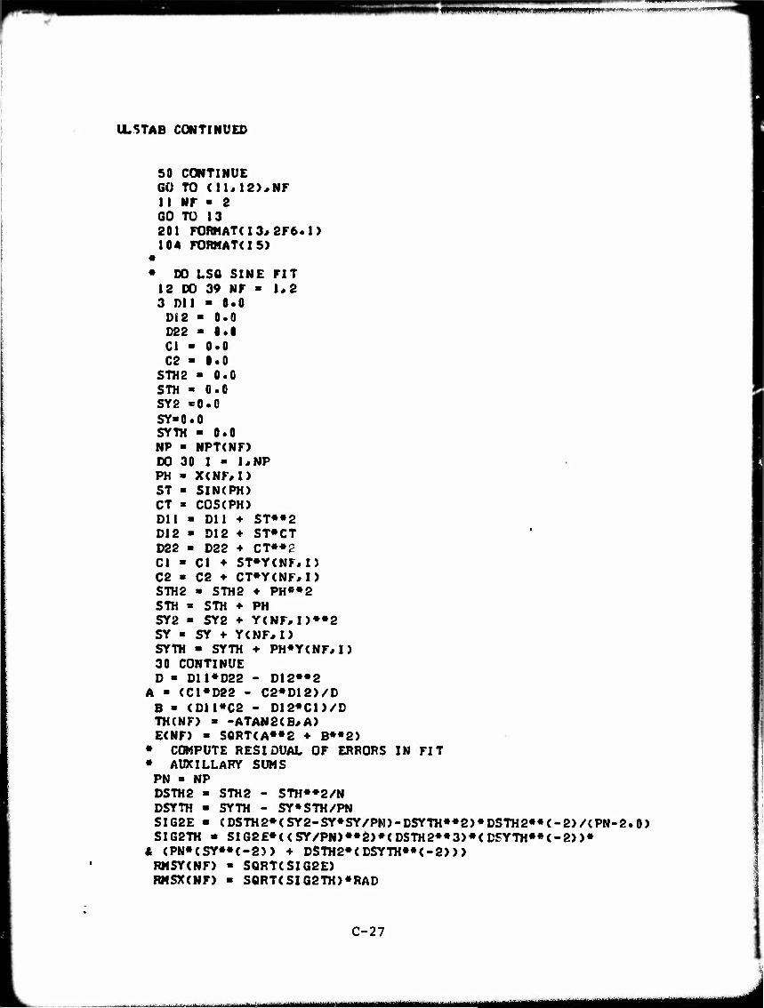
wwwpwwwwiwii' m»v '■, mn J >^^;i^ipiwi»f*w««Mr'<» W
ILSTAB CONTINUED
SO CONTINUE 60 TO (11*12),NF 11 NF - 2 GO TO 13 201 FORMATU3, 2F6.1) 104 FORHATdS)
» DO LSO SINE FIT 12 00 39 NF - 1*2 3 DU - 8.0
Di2 ■ 0.0 D22 - 0.0 Cl - 0.0 C2 ■ 1.0
STH2 - 0.0 STH « 0.0 SY2 -0.0 SY-0.0 SYTH - 0.0 NP ■ NPT<NF> DO 30 I > 1«NP PH ■ X(NF#I) ST ■ SIN(PH) CT « COS<PH> Dll - Dll ♦ ST««2 D12 > D12 D22 - D22 Cl ■ Cl ♦ C2 » C2 ♦
♦ ST»CT ♦ CT»*2 ST»Y<NF*I> CT»Y<NF*I)
STH2 « STH2 ♦ PH««2 STH « STH + PH SY2 - SY2 ♦ Y<NF, I)»«2 SY ■ SY ♦ YCNF^I) SYTH - SYTH •»• PH*Y(NF*I) 30 CONTINUE D - Dll»D22 - D12»«2
A - (C1«D22 - C2*D12)/D B ■ <D11»C2 - D12«C1)/D TH(NF) > -ATAN2(B#A) E(NF> » S0RT<A*»2 ♦ B**2)
• COMPUTE RESIDUAL OF ERRORS IN FIT • AUXILLARY SUMS
PN » NP DSTH2 ■ STH2 - STH«»2/N DSYTH - SYTH - SY«STH/PN SIG2E ■ <DSTH2»(SY2-SY*SY/PM)-DSYTH«»2)»DSTH2««(-2)/<PN-2.0) SIG2TH • SIG2E«<<SY/PN)*«2)»<DS,rH2««3>»<DSYTH»«(-2>)»
A <PN«<SY»»(-2)> ♦ DSTH2»<DSYTH»*<-2))) RMSY(NF) > SQRT(SI62E) RMSX(NF) » SQRT<SIG2TH)*RAD
C-27
^-~L- ««■^M^HMMMMIMBMHHBMM J
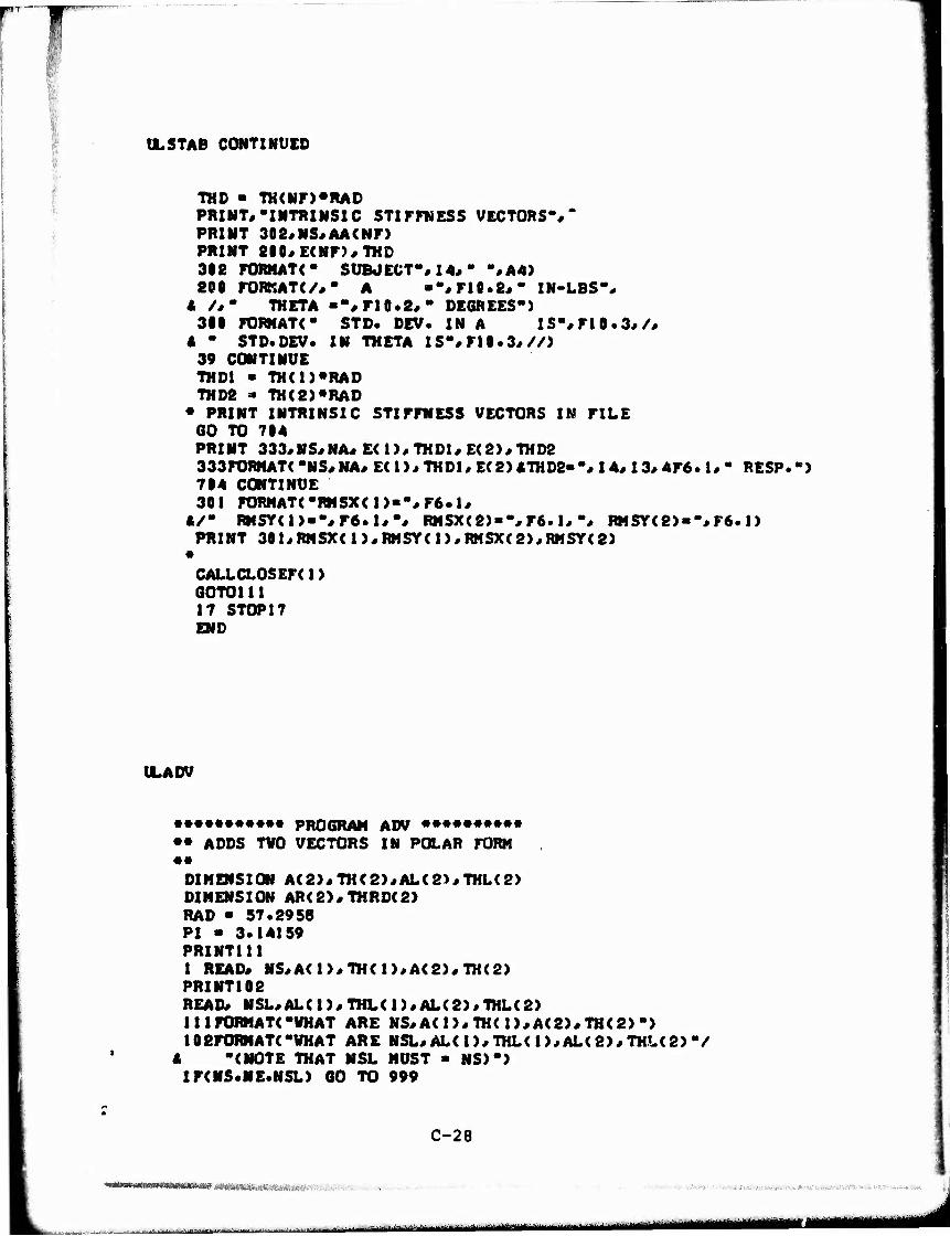
I
ÜLSTAB CONTINUED
TOD • TH(Nr>*RAD PRINT«'INTRINSIC STIFFNESS VECTORS"/* PRINT 302«NS«AA(Nr) PRINT 2«0*E<Nr)#THD 3ie FÜRNATC SUBJECT«« 14«- %A4) SCO rOBKATC/*" A "•#rH.8«- IN-LBS-«
A /#" THETA ••#ri0.2«* DEGREES*) 311 FORHATC STD. DEV. IN A IS"« FI 0 .3,/,
A " STD.DEV. IN THETA IS"#ri0.3#//} 39 CONTINUE THD1 - TH(I)*RAD TOD8 - TH(2}*RAD
• PRINT INTRINSIC STIFFNESS VECTORS IN FILE GO TO 714 PRINT 333«NS«NA«E(1)/THD1«E(2>/THD2 333FORHAT( *NS« NA# E( 1)« THD1« E( 2) «TOD2-"« 14« 13« 4F6. 1« " RESP. ") 714 CONTINUE 301 F0RMAT(*RMSX(I>--«F6.1«
«/" RMSY(1)»-«F6.1«-« RMSX<2)»%F6.1#-, RMSY<8)«"« F6. 1) PRINT 301«RHSX(1)«RMSY(1>«RMSX(2)«RHSY(2)
•
CALLCLOSEF(1> GOTOl11 17 STOP17 END
tLADV
••••••••••• PROGRAM ADV •••••••••• •• ADDS TWO VECTORS IN POLAR FORM ••
DIMENSION A(2}«TH(2)«AL(2)«TOL<2> DIMENSION AR(2)«THRD(2) RAD - 57.2958 PI - 3.14159 PRINT111 1 READ« NS«A(1>«TO(1)«A(2)«TH(2> PRINT102 READ« NSL«ALC1)«THL(1)«AL(2)«THL(2) 111 FORMAT("WHAT ARE NS«A< 1)« TH( 1>«A(2>«THC2> "> 102FORMAT("VHAT ARE NSL« AL( 1>«THL( 1 >«AL(2>«THL(2> "/
4 "(NOTE THAT NSL MUST ■ NS)"> IFCNS.NE.NSL) GO TO 999
C-28
...., ...........^ ■ - -■■■-■-' -■■ - — '—V-.L..,,,.. , ^.......vt^MMmmemmmmmimimmmiatm
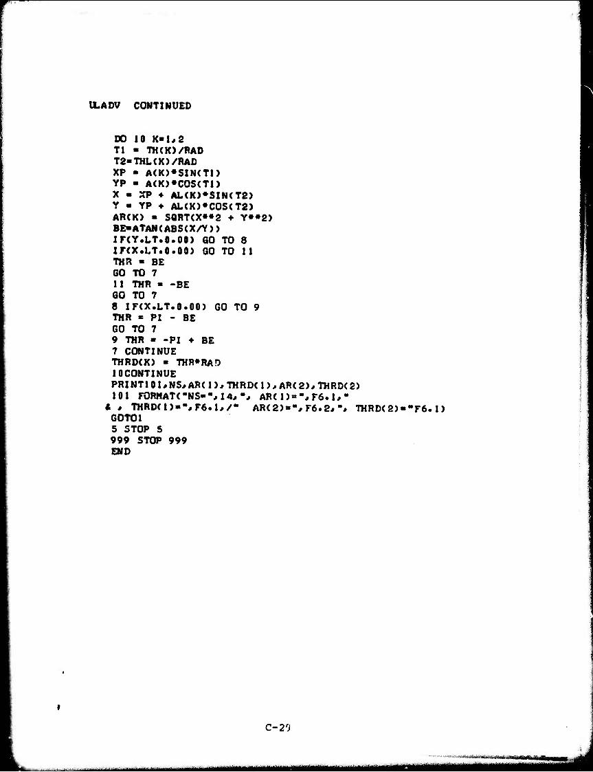
ILADV CONTINUED
DO 10 K-1,2 Tl - TO(K>/RAD T2-THL(K)/RAD XP - A(K>«SIN(T1> YP - A(K)*COSCTl) X - XP ♦ AL(K)*SIN(T2> Y - YP ♦ AL<K)«C0S<T2) ARCK) - S0RT<X»»2 ♦ Y»»2) BE-ATAN<ABS(X/Y)> Xr<Y.LT.0.00) GO TO 8 Xr(X.LT.O.00> GO TO 11 THR ■ BE GO TO 7 11 THR - -BE GO TO 7 8 IF<X.LT.0.00) GO TO 9 THR « PI - BE GO TO 7 9 THR ■ -PI ♦ BE 7 CONTINUE THRD<K) » THRORAD 10CONTINUE PRINT101/NS*AR<1)*THRD<1),AR<2>#THRD<2> 101 FORMAT« "NS-'M 4.,-., AR< 1) = -, F6. 1, "
I * THRD(1>-%F6.1*/- AR(2)»",F6.2*-* THRD<2)--F6. 1) GOTOl 5 STOP 5 999 STOP 999 END
C-2'J
ii n ———■—^ «•^M^MMMMnMH
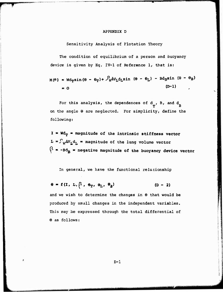
^■'f
APPENDIX D
Sensitivity Analysis of Flotation Theory
The condition of equilibrium of a person and buoyancy
device is given by Eq. IV-1 of Reference 1, that is:
M(e) « wdTsin(e - eT)+>pwAvLdL8in (e - oL) - BdBsin (e - eB)
o (D-l)
For this analysis, the dependences of d , B, and d T B
on the angle 9 are neglected. For simplicity, define the
following:
I - WdT ■ magnitude of the intrinsic stiffness vector
L =j w^L^L ** ,na9nitude of the lung volume vector
Y ■ ~BdB « negative magnitude of the buoyancy device vector
In general, we have the functional relacionship
e - f(if L,p , eT, 9L, eB) (D - 2)
and we wish to determine the changes in 9 that would be
produced by small changes in the independent variables.
This may be expressed through the total differential of
9 as follows:
D-l
■■ ■ ■ HMMMMIIMI

rSSSS
de - f1dl + fLdL + fßd^ + feTd9T + ferd9L + fe de e^ »B 'B
where: fj ^Ttt/al, tL «Of/^L, etc. ^ . JJ
fjdl, ^dL, and f^d^ are in radians.
To evaluate these partial derivatives, it is most
conveniL ,t. to implicitly differentiate equation (D-l) .
This yields the following:
fL «^e/aL = -^Ti^re
fn «'Be/So = -
f ^e/-e = -?il4^T feT ^^/^T ^M^e
eL ^ /d L TM7^9
eß " ^M^e
By differentation:
-7)M/>J>I ~ sin (9 - eT)
OM/^iL «= sin (9 - eL)
^c>M/?fi = sin (9 - eB)
^H/C^T = -I cor. (9 " GT)
OM/C^L " ~L cos(e - eL)
^H^Gß = -E cos (8 - GB)
(D-4)
(D-5)
(D-6)
(D-7)
(D-8)
(D-9)
(D-10)
(D-ll)
(D-12)
(D-13)
(D-14)
(D-15)
^M/?9 « I cos (9 - eT) + L cos (9 - 9L)
■i-S^cos (8 - eB)
(D-16)
D-2
■ ■ .J..:..^.-.. ■ ■ '■ - — ■ ■ ■ ■
-■ ■■ ■ _^_^.

ft^^nm^m •'
With these relations, each of the partial derivatives
^1' ^L' ^B' etc.) in Eq D-3 can be calculated for a
particular case, and the sensitivity of 6 to small changes
in each of the other variables evaluated. It may be noted
that the partial derivatives may be very large if ^M/^6
is very small. The value of jM/06 is the vertical component
of the resultant stiffness vector, and is equal to the
magnitude of that vector at equilibrium (the horizontal
component is the turning moment, which is zero at
equilibrium). Thus the condition of small cM/^S corresponds
to the situation of small resultant stiffness vector, when
the equilibrium is not very stable. It is not surprising
therefore, that small changes in the variables would lead
to large changes in 6 under those conditions.
The sensitivity of 6 to experimental errors in the
various vector quantities is illustrated below for two
cases cited in Reference 1 and summarized in Figs. D-1 and
D-2 (which are reproduced from Figs. A-3 and A-4 of
Reference 1) . The results are:
Error in 6 for 1° error in 0^
Error in 6 for 1° error in 6^
Error in Ö for 1° error in 6p
Error in 6 for 1 percent error in I
Error in 6 for 1 percent error in L
Error in Ö for 1 percent error in ^
D-3
Fig. D-1 RSV =41
Fig. D-2 RSV = ?6
2.2° 0.65°
0.47O 0.15°
1.6° 0.19°
0.72O 0.81°
0.74O 0.45°
1.4° 1.3°
- 1 -- tii mfrM^hi—-——nggHimi IM 1 " >^****j**um****mmtm**l*m i

• Mim I
Since the value of the resultant stiffness vector
<J»M/^e is not particularly small for either of these cases,
neither represents an extreme situation. Yet the possible
errors induced in the calculated values of 6 could be
quite large. For example, if experimental errors of 10
percent in I, L and ^ produced additive errors in B, the
resultant error in 6 would be 28 degrees for Fig. D-l
and 25 degrees for Fig. D-2.
A more extreme situation is represented by the
calculation for Subject 60 of Reference 1. It has been
assumed here that the buoyancy device and its buoyancy
vector are the same as that for the Fig. D-2 situation.
The result of the sensitivity analysis is:
Error in 0 for 1 degree error in eT
Error in 0 for 1 degree error in O^
Error in 0 for 1 degree error in 0p
Error in 0 for 1 percent error in I
Error in 0 for 1 percent error in L
Error in 0 for 1 percent error in ^
Subject 60 RäV = 13
0.43°
1.68°
l.lio
3.46°
2.12°
5.65°
For this case, where the magnitude of the resultant
stiffness vector is small (13)/ errors in I, L, and ^
have a large effect on the accuracy of the calculated
D-4

*IV
value of 9. For example, if experimental errors of 10
percent in I, L, and 6 produced additive errors in 6,
the resultant error in © would be 111 degrees, according
to the sensitivity analysis. It is noted that the use of
Eq D-3 to calculate finite changes in 6 for finite changes
in the other variables is accurate only for small increments,
Thus the large increments in 6 which are calculated here
are not exact, but indicate only the potential for large
errors which exists.
D-5
- ■ -"—*•• —— ■ - ■MM MHMMMI
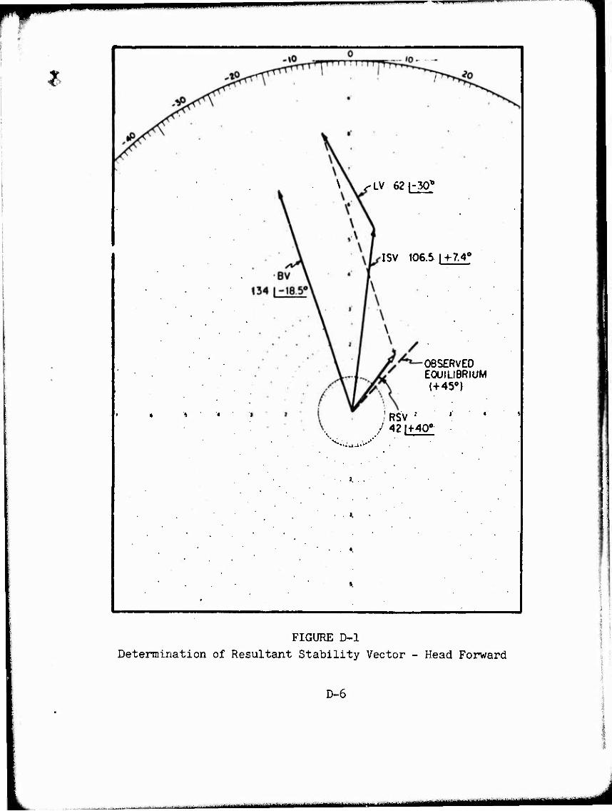
IP— "——
\ \ ^-LV 62|-30t
ISV 106.5 | -H7.40
OBSERVED EOUHIBRIUM (+45°)
/ RSV :
NJ
FIGURE D-l Determination of Resultant Stability Vector - Head Forward
D-6
»ii-iii,ir-ni in i^amiBajMM—tülMlIlM—iaai MMBBMM l&MlUMHMMMMMlMi
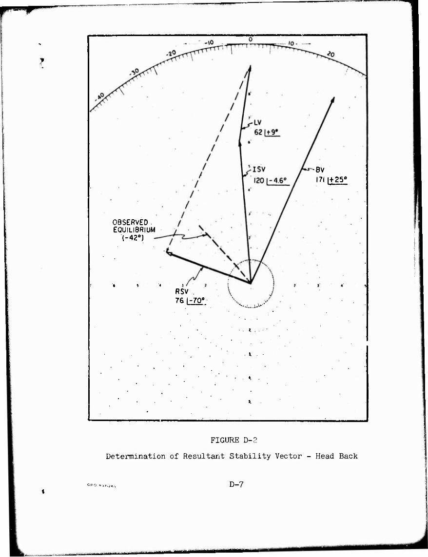
OBSERVED. EQUILIBRIUM
1-42°)
' * » « j
RSV 76 1-70°
^.^^>-
i .
BV 7l|+250
FIGURE D-2
Determination of Resultant Stability Vector - Head Back
SPO HC,?.;,,., D-7
■HII.I^^.I.M.II it- ii inmniiiiiiii n


![FINAL REPORT SOIL INVESTIGATION WORK FOR A ... 1...Job no. 101/05/2018 2 [ 1 ] INTRODUCTION : Gujarat Power Corporation Ltd.,Dholera proposes soil investigation work for construction](https://img.dokumen.tips/doc/110x75/5e6c1d43bb87d52ec46c2fe2/final-report-soil-investigation-work-for-a-1-job-no-101052018-2-1-.jpg)