Embed Size (px)
Citation preview
AD-A 185 636AFIT/GST/ENS/87J- 12
8i [FILE COPY
DTICA ELEC'TE'_-
OCT 0 1 1987'
cPD
Using Concept Mapping to DefineProblems and Identify Key Kernels
During the Development of a
Decision Support System
THESISMichael R. McFarren
Captain, UASF
AFIT/GST/ENS/87J- 12
Approved for public release; distribution unlimited
V arffifnt" hw~ Lem


AFIT/GST/ENS/87J-12
Using Concept Mapping to Define Problems and Identify Key
Kernels During the Development of a Decision Support System
THESIS
Presented to the Faculty ot the School of Engineering
of the Air Force Institute of Technology
Air University
In Partial Fulfillment of the
Requirements for the Degree of
Master of Science in Operations Research INSPCCTECC
F "
Michael R. Mc Farren. B.S., M.B.A.
Captain, USAF
June 1987
Approved for public release; Distribution unlimited
- - - - - - -

Preface
This thesis effort would not have been possible
without the support and encouragement of many people.
I would like to thank all the members of the RAAP working
group for their patience and understanding through all
the hours of interviewing and to the entire GST 87-M
class for their constant challenges and inspiration.
In particular I owe the largest debt of graditude
to three special people. Colonel John E. Rothrock made
it possible to validate the intire concept mapping prqcess
because of his visionary thinking. Lt Col John "Skip*
Valusek, my mentor and friend, introduced me to the
need and inspired me with the challenges. And to Sandra,
my wife, who took the burden of running our home and
lovingly cheered me on. Thank you all.
Michael R. McaFrren
Hi
Table of Contents
Pagereface . . . . . .. ii
List of Figures . . .. vi
List ofrTables . ................. ix
Abstract . ................. . . . x
1. Introduction . IIntroduction ..............Ba c k g r ou.n d.. .* 2Formal Training in Lecision Making . . 4Descriptive Technique ...... . . .The importance of Describing Problems .The Problem ........... ..
Tho Challenge ............. 10Scope . . . . . . . . . . . . . . . . . 10Hypotheses 1 . . .yp2. . ....... . 2The First Basic Hypothesis ....... 12The Scond basic Hypothesis• . ....... .. 14Uener&a Approach ............ 14Sequence of Presentation ........ 10
1I. The World of the Decision Maker .... . . .Introduction .I.S............The Decision Maker's nvironment . . . . LProblem Domain - Problem Space ..... LWDefinition of Decision Making ..... 21The Fog of Decision Making ....... 21Educating Decision Makers ....... 24The Decision Making Process ... ....... 27The systematic Approach..• ........ . 2The Meed for Problem identificaiton . . 2The Art of Yrobiem Definition ..... .11)SS and Problem Definition ... ....... .Requirements for & Capturing Process . .
Uonceptualization ........... J4Uood Decisions ....................... .Decision Support Systems. ................Value of DSU .......... .............. .7Kfficiency vs Effectiveness ...... JPerceptions Inherited by the V)5 . . . .Concept Mapping ..... ............ 40The Vroblem Definition Process ... ..... 41Why is It important to know and define theKernel? ............... ................ 42Conciusion ........................... 4.
Ill. Concept Mapping .......... ............. .. 44Introduction ........ ............. .. 44What is Concept Mapping? .......... .. 44
iii

Concept Mapping - Educational Derivative 4bKnowledge Representation Systems . . . . 4Difference between Concept Mapping andOther Schemes ............. biThe Supporting Theory of Concept Mapping b4Theory of Memory - Knowedge-Lines . . . bSchema Theory ..... ...... . 0OAusubol's Theory of Education ..... 0Supporting Points of View ....... u•Why Concept Mapping . ..........
The Power of Concept Mapping ......... 0Applying Concept Mapping to the Problem. 07Reasons for Selecting Concept Mapping 08Conclusion ............ ............... O
IV. The Concept Mapping Technique ...... ........ 70introduction "......... . . . . .. 70Learning How to Concept Map ..... ...... 73Preparing for Concept Mapping ..... 7JConcept Mapping Activities ............ 74The Concept Mapping Interview ..... 74Scheduling the Interview ...... ........ 7bSetting-up the Interview Environment . . INThe Interview ....... ............. .aConcl,.usion . ................
V. The Problem Definition Process (YUY) . . . .
Introduction ...............
Adaptive Design . . . ............. SThe ?UP and the Adaptive Design . . . .
The Pocess .............. W4The ag. . ... ................Problem Description - The Mole of ConceptMapping. ... ..................... .. uOProblem Definition. ....................... 100Task Analysis. ...... .............. . O1Dat& Analysis. ...... ............. .... 1Feature Charts and Storyboards ..... .... 0Mv&auation ............ ............... lOwKernels.. . ........ ..................... L.Conclusion . . ................................
VI. Examples of Concept Mapping Applied to Problem 1iJIntroduction . . . . . . . . . II1SSource Of Examples. .... ........... .... 1
Crude Maps . ........... ............... 114Why the Header may not Agree with theKernels . . . . . . . . . . . . .. . 11bExample I - buying C r. ......... . 11Example 2 - Compromised Information . likxample 3 - Adams' Tanks. ..... ........ 121gx&mple 4 - Pilot Training Scheduling 121Example b - AWACS Manpower Manager . . . 1.1Example 0 - Tactical Nukes. .... ....... 2
iv
V-**
Conclusion . . . . . . . . . . . . . . . Li
V.l. Application of Concept Mapping on .KAAk' . . . 134Introduction .............. 1•4The Advantages of the HAAk kroblem, Domain 13bwThe Xxporiment ... 13WS- background ........... 141Mxpewimnt&L Procedure .*. 144Findings and Observations ....... 140Individual . 147Aggregation .............. 184Observations .............. 8Conclusion ............... W
VIII. Results, ftcommendations, and Conclusions . . L4Introduction. . ..............................Findings and Results . ....... .......... 1u4Concept Mapping as a Too. ..... ....... 1W4The ?UPas an Integrator. .................. WORecommendations . ...................................
Technique knhancemnta ...... ........ IwoHarness the Power of Automation . . . . ISConcept Mapping Applications. ....... .. 200Apply to Mor*e roblems ......... ...... 200Concept Mapping and Later Stages of 1)5Development ......... .............. 200Follow-up with the HAAk. Problem . . .. 201Apply UK to the USAF Acquisition System 201PDU Knb&ncements . ......... ............ 202Conclusions .............. .............. 20
Appendix A: Introductory Lesson toConcept Mapping ......... ........... 205
Appendix 8: Storyboard and Uvaluation of a
Decision Supprot Syrtem. .... ....... ....
bibliography ............... ..................... 281
Vita...................................................287
V
p ' ]

List of F'igures
Figure Page
I-i Courses from AIYIT Catalog 1W85-87 ......
2-1 Potential cognitive subtaask in thedecision making process ........... 28
2-2 A varitey of Algorithms for decisionmaking y author .... . 2W
2-3 Inputs to diagnosing and defining theproblem . . . . . . . . . . . . . . . . . . . ý0
3-1, A concept map for water showing some relatedconcepts and propositions ................ 4.
3-2 A concept map for states showing the "RuberSheet" effect . 48
3-3 Level band ................. b7
3-4 K-Line Attachments ............. b
3-b Memory Trees ................ bw
3-0 Mental Manipulations ............ 00
3-7 Ausube*Ls Key Concepts ........... 04
4-L Activities to Prepare for Concept Mapping . . 71
4-2 Concept Mapping Activities ......... 72
4-3 Issues of Interviewing ........... 82
b-A User's formal and correct requirement and thecorresponding information system design . . .W
h-2 The Problem Definition Process ....... ....... 7
5-3 The Predesign Cycle .......... ............. W.
5-4 Feature Chart . . ............................ .07
0-i Concept Map: buying a Car. . ........ ......... 7
0-2a Concept Map: Compromised Information -Problem Space .......... ................ .. i
U-2b&c Concept Map: 'Compromised lnformation" . . . LO
vi

U-ra iecbenik's Ordering of Key Concepts 1 . . L20
(-Jb Concept Map: First Cut at Problem Space . 127
O-;5 Concept Map: First Cut at Decision Process 128
i-3d F Cna Concept Map of Decision Process . . . L3O
0-4 Concept Map: AWACS Manpower Management . . 1S1
7-1 MAAI' Summary Paper ............ 148
7-2& CoL Aothrock's Presentation to TACT 412 . . LbO
7-2b Col othrock's Presentation to OVER 701 . . 1IL
7-2c First Interview: Problem Areas ...... lb
7-2d IAULA Process ............... 1b4
7-2* class notes . I bb
7-2f Second Interview ........... ............. L57
7-2g Western Advantage ...... ............. ... bd
7-2b MAA2 and TechnoLogy .... ............ ... bW
7-21 Inductive vs Deductive ..... .......... . .b
7-2j HAA 's Way of Thinking ..... .......... .. A
7-2k HAA'a 9volution ....... ............. 102
7-21 MAA is Not..... . ...... ................ L02
7-2m Additions to Figure 7-2& ....... ......... 104
7-2n Additions to Figure 7-2b ....... ......... lb
7-20 Master Links to &ll 7-2 Concept Maps . . . LU
7- UMaJ &arrison's Concept Map of HAAY . . . . 0I
7-4 Col Kline's Concept Map of HAAY . ...... LI1N
7-5a Mr Allen's First Interview ... ........ ... 172
7-5b Mr Allen's Second interview ...... ........ 11"
7-0 Mr Converse's Concept Map ............... ..
7-7& Mr F&pagni: Definition of HAAA? ....... ... 177
vii
r - - '. 'w u~-,.-.*f~v '.v'k

'7-7b Yap&gni: •AA Process ... 78
7-H& Lt lye: HAA Definition . ........ 179
7-Ob Lt lye: MAAk Pr'ocess . * 180
7-W& CoJ.Suter: HAA Definition ........ 182
7-Ub Col Suter: MAAk'a Role in the Decision
7-10 Aggregated Definition of AA. ....
viii

List of Tables
Table ?age
0-i ?osllbLe Kernels .............. 1ib
U-a Urechaniks' List of Key Concepts ...... 123
V-2b Trapp's LAst of Key Concepts ........ 124
fS-2c Trapp's Firt Ordering of Key Concepts . 12b
0-2d Identified Kernels ... ......... t•
7-I Key Concepts in the Definition of AAA& . . 184
7-2 Foxuible Kernels in the HAA Process .... . 8.7
ix

CHAPTER 1
INTRODUCTION
1.00 Introduction:
Where do I begin? ... Every Decision Support System
(DSS) designer/builder must ask himself this question
every time he sets out to build a support system.
This hesitation at the start of a problem is not
uncommon. All humans have experienced this dilemma
when they are faced with a complex decision. Think
about the last time one of your home appliances broke
down. How did you go about getting it fixed? How did
you go about finishing the task that was started when
the machine failed? -Do you remember-all the steps you
took? What were all of the alternatives? What was
the first thing you did? If it happened right now what
would be the first thing to do? If you're like most
people, these questions are hard to answer and bring
back strong emotions like frustration, hopelessness,
or fear. And yet, these are relatively simple problems;
problems that have been solved before by you or others.
Although the DSS designer is not faced with the
same problems or emotions, he is faced with the same
questions. Where is the starting point? What are the
key points of the problem? This dilemma stems from
the lack of two important aspects of the problem. Every
)1
vwV I
r N5

decision maker must have 1) a clear definition of the
problem and 2) an understanding of the decision making
process used to solve the problem.
This thesis effort is an attempt to help the DSS
designer/ builder in him task of finding the starting
point. This paper introduces a method for defining
problems and identifying the decision process. The
results of this method aid the designer/ builder in
the construction of a DSS by pointing out the key points
or kernels of the problem where a DSS can assist a decision
process.
1.10 Background:
How the human mind works is an extremely interesting
topic that eludes complete understanding. Somehow the
human mind takes new information and stores it. Later,
when faced with a task that needs the information, the
mind recalls it and performs various operations on
it. These operations are known as cognitive processes.
These cognitive processes are used to accomplish tasks
such as problem solving and decision making.
There are times when a decision maker is faced
with complex or very difficult decisions. These decisions
require vast amounts of data, very complex cognitive
processes, or intricate sequencing of cognitive processe-
s. Under these conditions, the decision maker requires
2

som sort of help. This help in making decisions comes
in the form of a decision support system.
The DSS provides support for a particular cognitive
process when faced with & specific decision or problem.
A DSS is *" system, manual or automated, that aids a
decision maker in the cognitive processes of Judgement
and choice* (Valusek, 1988). To build a DSS, the cognitive
processes that make up the decision or problem solving-
process must be identified. This identification process
or search is otherwise known as defining or describing
the problem.
Problem definition requires the identification
of the solution process as an integral part of the DSS
design. This topic is crucial to the continued developm-
ent of DSS as a viable means to help decision makers
with complex tasks. Without a clear understanding of
the problem and how the decision process works, the
DSS builder is Just randomly producing aids that may
or may not be effective support for the decision maker.
Decision aids are too time consuming and expensive
to be built in a haphazard manner. A process is needed
to identify the key steps in the decision process, and
suggest to the designer which elements of the problem
will benefit the decision maker most. Its result would
be a list of decision making elements that, if necessary,
can be ranked in order of most to least supportive.
3

Each item on the list of decision making elements is
a potential kernel. A kernel is &. key decision element
in & decision or problem solving process which is a
feasible starting point from which to build & DSS.
Once the designer has the list, he can construct
decision aids that are based on the cognitive proctes
and effectively support the decision maker. Using this
approach, the decision maker receives the most effective
support that is technologically available in minimum
time and at least cost. This is a very appealing idea,
but how does a designer go about finding theme decision
elements? Is there an existing procedure to follow?
1.11 Formal Training in Decision Making:
When decision makers are formally taught how to
make decisions, they are taught two things: 1) Every
problem can be approached systematically, and 2) There
are a variety of problem solution techniques that can
be applied given the right problem. The thing they
are not taught is the skill to identify and define the
problem. The lack of formal training in descriptive
decision processes is a detriment to decision makers
(Keen, 1978:62; Leavitt, 1976). Both authors agree
that too little emphasis is placed on problem finding
as opposed to problem solving. Consequently, the decision
makers see decision making as & structured task and
4
concern themselves only with the content of the decision,
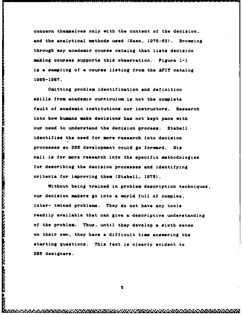
and the analytical methods used (Keen, 1978:82). Browsing
through any academic course catalog that lists decision
making courses supports this observation. Figure 1-1
is a sampling of & course listing from the AFIT catalog
1985-1987.
Omitting problem identification and definition
skills from academic curriculum is not the complete
fault of academic institutions nor instructors. Research
into how humans make decisions has not kept pace with
our need to understand the decision process. Stabell
identifies the need for more research into decision
processes so DSS development could go forward. His
call is for more research into the specific methodologies
for describing the decision processes and identifying
criteria for improving them (Stabell, 1975).
Without being trained in problem description techniques,
our decision makers go into a world full of complex,
inter- twined problems. They do not have any tools
readily available that can give a descriptive understanding
of the problem. Thus, until they develop a sixth sense
on their own, they have a difficult time answering the
starting questions. This fact is clea*rly evident to
DSS designers.
5

OPEN SM -Qua/thde Decisio Making. OPER 742 -AalnUiis for Defesm Dedsion.
Cmdwtl 4 Cediw 3
N-qvisitu u PmvquWit None.
This ita tmr -i e course i This course discuses the role of analysisopermions research techniques. Emphasis in in defeDe decisions and examines both thethe course is directed toward u standing limitation and calities of analysi in theand application of the techniques to m-making praces. The distinctivemanagerial problem solving and decision mak. features of this course are its broad coverageing rather than toward theorem derivations or of analytic aids to decision-making and itsprooM. Major topics covered include linear focus on the needs of the user. Specifc topicsprogramming, inventory theory, queueing include- the need for analysis in public sectortheory, and decision theory. decisions. the basic framework for analysis.Text- An Introduction to Management Sci quantitative and qualitative methods
ewe. by. Aade . Sweeney and tanc implementation, and pitfalls and
WINOML Alimitations of analysis.
OPER 563 -. lmar PrOVmmiag and ExtFm- OPER 760 -Opwsdom Remrck ILdean. Cn~r~d 3
C.'ditw 4 Phrreeqiu'sa OPER 660, MATH 592,e 'rquisir- None. MATH 692
-This is the initial course in the opera- This is the second of a two coursetions research sequence. The course begins sequence introducing operations research towith a discussion of the role of quantifcation management students. The two coursesand modeling in decision making and resource survey operations research models andmanagement and an overview of Air Force methodologies and examine the role of opera.quantitative analysis applications The primary tions research in managerial decision making.types of operations research models covered This second course emphasizes probabilisticin this first course are deterministic mathemat- models and cover the topics of inventoryical programming models, like linear program- models& queueing models, a brief look at simu-ming. the transportation model, and game lation. Markov processes, and reliabilitytheory. The strengths and weaknesses of models. Examples and cases from the USAFthese operations research models are environment are emphasized.presented and discussed in the context of Text: Principles of Operations Research formilitary applications. Management. by Budnick et at
Figure 14-. Courses frou AFIT Catalog 1985-87
0 I

1.12 Descriptive Techniques:
There are several ways to describe problems. Two
of the most common are word description and visual images.
Both have advantages and disadvantages in performing
the descriptive role for problem definition. But are
these the best for problem description?
Using word descriptions is a lengthy, time consuming
and sometimes confusing exercise. The decision maker
must. fully describe each detail of the problem so another
person can receive the correct meaning. If the problem
is at all complex, the description may become very lengthy
and cumbersome. The comprehension of the problem rely*
heavily on the ability of the author to use the language
and organize the facts in the description. Also the
presentation of the information is forced into a linear
form which is not always conducive to effective learning.
However, the method is excellent in recording the smallest
details and relationships of problem elements.
Visual images include pictures, diagrams, charts.
blue- prints, etc. These are tools that depict a problem
in a concrete manner using lines, curves and shapes
to represent the elements of the problem. An image
is universally understood and therefore overcomes some
of the language barriers inherent in word descriptions.
Images are one way to enhance the learning process by
aiding the ability of the learner to recall. However,
7

images cannot provide the intricate detail needed for
relating complete understanding of all the details in
a problem.
There is another method developed by educational
psychologists that may offer some ability to enhance
the advantages of both descriptive techniques. Concept
mapping is a combination of both word description and
visual images. It is designed to represent concepts
as they are understood by the mind. This capability
gives two main advantages. First, the mind can more
easily learn from the map. Learning is enhanced because
the map is a visual representation of the concepts and
their links to each other. The map shown the links
in the same manner as the mind links and stores the
concepts in memory. Second, there is no restriction
on the organization of the map. Information is not
locked into a linear presentation..
1.13 The Importance of Describing Problems:
When a decision maker realizes he cannot handle
a complex problem as effectively as simpler problems,
he calls for decision support. In the past, decision
support might have been a ledger book, a wall chart,
or drawings. Today the realm of decision aids extends
into the high-tech world of computers, simulation, and
artificial intelligence (AI). But the underlying dilemma
a
8 R ' '- ' ~*

still faces the designer. What is the problem? What
are the decision processes that should be helped by
a decision aid? The only way to answer these questions
is to describe the problem. A descriptive process is
needed.
Why is the descriptive process of decision making
so important? Keen and Scott-Morton explain it best
when they say: *Decision support requires a detailed
understanding of decision making in organizations.
A descriptive framework provides the basis for prescript-
ive design; that is, to 'improve' a decision process,
one must first define and analyze it' (Keen, 1978:61).
As & means to aid the designer/decision maker in
his understanding of the problem space and description
of the decision process, this project became one of
identifying a descriptive process that supports the
identification of key decision elements or kernels,
so that the designer produces a pertinent and effective
decision support system (DSS)./
1.20 The Problem:
K---How-dowe-a DS8 designer identify the kernel(s)
of a problem, from the user's perspective, and develop
a design for a DSS from them? The problem arises because
DSS adaptive design says 'start small and grow, but
there are no suggestions on where to start.
9

7
1.21 The Challenge:
Can concept mapping techniques be developed into
a user oriented tool to help identify kernels?
1.30 Scope:
This thesis addresses the primary challenge by
developing the tool, concept mapping, as a means to
identify kernels in a decision process. This is a
descriptive process that defines the problem space.
describes the decision process, and identifies the key
steps of the decision process as potential kernels.
Beyond this initial challenge is the challenge of integrating
concept mapping into the adaptive design process.
This thesis effort will take the technique of concept
mapping and use it to extract the information about
a problem from the decision maker himself. The result
of this extraction should be a well defined problem
space, a sufficiently described decision process and
a means to identify the kernels. Finally, the effort
turns to integrating concept mapping into the adaptive
design process. The integration of concept mapping
into the adaptive design process is accomplished through
a process called the problem definition process (PDP).
As a means of development of the concept mapping
technique and experimentation with the PDP, several
10
- 6 j~% -I 'uvg VW V% rW W .-W P.~nm N1J
test cases of various DSSs were attempted. A few of
these test cases are reported later in chapters 5 and
a of this paper.
Because the scope of this project is to find a
way to identify kernels, there are several associated
areas identified that were not investigated. These
areas may be the basis for further research but are
beyond the scope of this project.
The first of these areas has to do with individual
perceptions. Since different people have different
perceptions of problems and how to approach them, they
will have different details in their decision process.
Therefore, no attempt will be made to determine the
"best or optimal' decision process. Only the *accepted
or agreed' decision process will be found using the
concept mapping technique. Much more research into
the basic understanding of cognitive processing of the
human mind needs to be done before evaluations of the
effectiveness of processes can be accomplished.
Pursuing this idea of cognitive optimization, no
suggestions nor recommendations will be offered to the
expert about changing his cognitive procedures to optimize
his/her process. The expert is just that; an expert.
S/he has far more experience working his/her problem
than the analyst/designer. Therefore, any suggestions
made would be based on total supposition since no actual
11

studies have come forth explicitly showing one cognitive
procedure as more effective than another.
A third topic not addressed by this effort is the
automation of the concept mapping technique. There
are several places where automation may be helpful to
the researcher while actually producing the concept
maps, but that is beyond the purpose of this effort.
1.40 Hypotheses:
This thesis was designed around two basic hypotheses
that are supported by meveral beliefs. Following are
the hypotheses and the beliefs. By showing each of
theme beliefs to be true, the hypothesis is then assumed
to be valid.
1.41 The First Basic Hypothesis:
Concept Mapping can, in sufficient detail, represent
an individual's understanding of a problem and his de-
scription of the decision process in order to identify
kernels for the design of a decision support system.
A. Multiple concept maps, created on the same problem,
will have similar main concepts and key areas. This
similarity should be seen between earlier and later
maps of the same person and also among maps of different
people.
12

B. One or more of the main concepts (key decision
elements) will be easily identified when comparing multiple
concept maps of the decision process. These main concepts
will be the kernels.
C. As expert's perceptions change over time, unimpor-
tant issues will drop from the problem space. Thus,
the key decision elements in a problem will repeat and
be identified when compared with previous maps.
D. Concept maps are simpler to read because they
present the information in the same manner that man
stores information in his mind. This concept makes
it easier for others to achieve the same understanding
as the expert who originated the map.
E. No two people will construct identical maps on
the same problem space, nor will the same person repeat
identical maps after a significant period of time.
But, identical key decision elements from the decision
process will be repeated. This will lead the designer
to give more credence to those elements as kernels than
others.
13

1.42 The Second Basic Hypothesis:
An explicit problem definition, which includes
a thorough definition of the problem space and a complete
detailed description of the decision process involved
in the solution of the problem, is essential to the
effective design process of decision support systems.
A. Kernels can be identified only after the designer
has explicitly defined the problem.
B. All problems contain elements of a decision process
that traverse the entire spectrum of "structuredness".
This means that some steps are highly structured while
others are not. (Keen and Scott-Morton) (Simon)
1.50 General Approach:
To meet the challenges, this thesis divides into
several goals which outline the approach taken to solve
the problem of kernel identification. The first goal
is to develop a tool for relaying understanding between
individuals. With a tool of this nature, a DSS designer
could extract an expert's understanding of the problem
and how he goes about solving it. The tool selected
in this project is & technique from the field of educa-
tion called Concept Mapping. Concept Mapping has been
shown to be an effective teaching tool for relating
14

new concepts and their meanings to students. By slightly
altering the process used by education, the concepts
and meanings about a problem can be extracted from an
expert by the designer. With this technique an expert's
understanding of & problem and his description of the
decision process can be captured. See chapters 3 and
4 for further discussion and explanation.
The second goal was to develop the method of explicit
problem definition. That is to say, what are the steps
in extracting the information from the expert? Fully
describing or understanding the problem requires two
distinct steps. The first step is to clearly and concisely
define the problem space based on the user's perception.
Once the problem is defined, the second step is to identify
the key elements from the user's description of the
decision process. Include all the key decision steps
that are identified as potential kernels.
Once the problem is described or explicitly defined,
the designer can then complete the challenge of this
thesis and identify the kernel(s). Therefore, the third
goal was to show that the concept mapping of the problem
definition and decision process does help identify the
kernels of the problem.
The fourth goal was to recommend to the DSS designer
how he can incorporate the steps and tools above into
the adaptive design process. Adaptive design is a process
15

that aids a designer in explicitly defining a DSS. In
other words, adaptive design finds a simple method or
procedure that a DSS designer can use to describe the
problem and design the system. Chapter 5 explains in
detail the PDP that is proposed.
As a means to complete the goals above and verify
the hypotheses, two types of test cases were used.
Since the main emphasis of the effort was to identify
the kernels for the design of a DSS, the majority of
the applications of concept mapping were on DSS projects
for classes and thesis requirements. To test the applic-
ability of concept mapping in a larger problem domain,
a second type of test case was chosen. Concept mapping
was applied to the definition and decision process of
Rapid Application of Air Power (RAAP).
1.80 Sequence of Presentation:
Each of the remaining chapters were designed to
present the findings, procedures and accomplishments
of this thesis effort.
Chapter 2 explores the decision maker's world.
It explains the reason a decision maker needs the skill
of a descriptive process as the main goal of the chapter.
Chapter 3 lays the ground work of theory behind
concept mapping. It introduces the current theories
of storing knowledge in the human mind and introduces
18

Ausubel's theories of educating.
Chapter 4 describes the concept mapping tool.
It explains what it is and how you can use it. A lesson
plan is presented that will te&ch the reader how to
use concept mapping.
Chapter 5 explains the proposed PDP. Although
each step is explained, the main emphasis is on the
role concept mapping plays in the process.
Chapter a documents the seven DSS projects where
concept mapping was used. There are several examples
of maps and kernels that wore found by the designers.
Some comments by the DSS designers about concept mapping
and the process are listed.
Chapter 7 documents the use of concept mapping
on RAAP. A very large unstructured problem was mapped
using several experts. Concept maps are shown which
depict the expert's understanding of the concept of
Rapid Application of Air Power. The results of the
mapping and the final recommendations show that concept
mapping can be useful in very large problem spaces as
a tool for planning and designing large systems.
Finally chapter 8 concludes the paper with a summary
of findings about the concept mapping technique as well
as the summary of results from the problem definition
experiments. Recommendations for future research and
the conclusion are included.
17

Chapter 2
The World of the Decision Maker
2.00 Introduction:
This chapter focuses on the abstract problem solving
world of the decision maker and that environment in
which s/h. operates. The rest of this discussion concen-
trates on achieving a better understanding of the conceptual
environment and explaining some of the terminology used
in the remainder of this paper.
2.10 The Decision Maker's Environment:
Conscious human thought resides in a conceptual
environment of memory, cognitive processes, affective
reflections, and behavioral responses. These factors
of the environment interact to sustain thought just
like air, light, water and earth interact to sustain
life. Within this environment, the human mind combines
these factors in the intricate process of decision making.
All humans continuously make decisions. However
the range and complexity of the decision spans from
basic daily decisions of 'when to eat' to abstract problems
like 'solving Maxwell's equations'. The mind performs
these feats by accomplishing complex cognitive tasks
like data collection, situation awareness, alternative
generation, evaluation, judgement, choice, etc.
18

2.11 Problem Domain - Problem Space:
There are three key terms that need to be understood
by anyone involved in defining a problem and identifying
the kernels of the decision process. The first term
is Problem Domain. The problem domain is a sphere of
understanding or range of problems associated with a
specific field. For example, aircraft maintenance,
flight take-off, and crew training schedules are in
the problem domain of scheduling.
The second key term is Problem Space. The problem
space is a conceptual area within the problem domain
that is defined and bound by the factors of the problem.
The bounds on the problem come from factor limitations.
Factors reach their limits when they no longer pertain
to the specific problem at hand.
The definitions of these two terms falsely lead
one to believe that there exists explicit delineation
between problem domains and spaces. Quite the contrary
is true. Problems are not delineated and are not easily
identified. The natural camouflage created by the lack
of delineation and differentiation can be seen in the
way information is communicated to the decision maker.
Problems are not presented to decision makers in
nice, neat, easy to understand forms. They are hidden
in the day-to-day noise of communication. Every decision
maker sends and receives thousands of pieces of information
19

daily, involving & variety of past and future decisions.
The decision maker must be constantly alert to the existence
of a possible problem that would require & decision
to be made. To help him/her identify any possible problems,
the decision maker must install and implement & variety
of sensors and control mechanisms. Each of these systems
helps keep him/her informed of the status of the organiz-
ation.
Concurrent with the sensing and control process,
the decision maker must also be creative. S/He must
search out and evaluate new alternatives to recurring
decisions. They must learn to look at old problems
in new ways and generate different alternatives for
enhancement of the decision process. Along with the
constant vigilance for new alternatives, the decision
maker must also be searching for new ways to make decisions.
Technology as well as perception changes very rapidly.
New wmays to look at a problem may be exploited by the
new technology. Thus the decision makers must remain
alert to take advantage of these opportunities.
These are the key functions and actions of a person
performing the complex cognitive tasks of decision making.
Since sensing, control and creativity are functions
of the decision maker, what then is Decision UakingX
20
2.12 Definition of Decision Making:
There are many variations on the definition of
decision making. Here are three that are commonly seen
in the literatur*e: 1) Decision making is & process
that produces & product called & 'decision'. 2) Decision
making is an irreversible commitment of resources.
3) Decision making is "& course of action consciously
chosen from available alternatives for the purpose of
achieving & desired result. Thus a decision is 1) &
choice, 2) the result of conscious mental activity.
and 3) directed toward a purpose* (Massie, 1981:170).
Another way to define decision making is to look
at how the decision maker models' the problem. *At
a minimum, complex decision making involves searching
for information about the current and desired state
of affairs, inventing possible courses of action, and
exploring the impact of each possible course of action.
All decision making involves predicting the likely con-
sequences of decisions, which suggests that the decision
maker have a *model' of the problem situation being
faced* (Brennan, 1985:130).
2.13 The Fox of Decision Making:
The environment of the decision maker is clouded
by several factors regarding the underst&nding of cognitive
activities within the mind. These factors cause knowledge
21

about the decision making process and the environment
that it resides in to be obscured.
1) Quantity of factors:
Many decisions seem to be simple at first glance
merely because the maker fails to comprehend the number
of factors that affect the situation. For example.
any scheduling problem is initially considered & relatively
simple assignment of one resource against another.
However, the assignment process must take into account
factors that are not prevalent at the surface. Factors.
such as the variable rate of production, worker unavail-
ability, and demand changes are all affecting the final
schedule. 'Confusion is not uncommon or unhealthy at
this stage; however, the decision maker cannot consider
all the facts and must develop a selective approach
for keeping the most important and relevant facts in
mind* (Massie, 1981:172). The decision maker copes
with this confusion by concentrating on the key aspects
of the decision at hand.
2) Lack of Judging Probabilities Under Pressure:
Decision makers are consistently required to estimate
the probability of factor results within a decision
environment. Two examples of questions that require
the decision maker to estimate a variable are: How
22

much conduit is needed for a building under construction?
What are the best lengths of conduit? In both of these
questions, decision estimates of the total length of
conduit as well &a the amount of waste depend on the
performance of the workers. The decision maker must
estimate the ability of the workers. This kind of decision
is usually accompanied by some stress. In this example
the stress is to complete the building on time, within
,code, and within costs. Are people good natural decision
makors? There is now considerable evidence that they
are not.
The maJor advance in descriptive researchover the last five years has been the discoverythat people systematically violate the principlesof rational decision making when judging probabi-lities, making predictions, or otherwise attemptingto cope with probabilistic tasks. Biasesin Judgments of uncertain events are oftenlarge and difficult to eliminate. The sourceof these biases can be traced to various heuristicsor mental strategies that people use to processinformation. In the final discussion a strongcase is made that Judgmental biases affectimportant decisions in the real world. (Howard,1980:9)
3) Human's inability to describe the process:
Understanding how people make decisions is essentially
"explaining how people manage to cope with the demands
of an environment, the complexity of which far exceeds
the range of possible human responses" (Hogarth, no-date:d).
Thus, the environment is clouded by the inability of
23

humans to describe their cognitive processes and ways
of thinking.
4) Complex Combinations of Processes used:
Another factor that clouds the understanding of decision
making deals with the ability to identify the combination
of simple processes used to solve the problem. Hogarth
believes that the human mind has only a limited number
of strategies or principles for making decisions. Often
these strategies are used in complex combinations.
This combining of simple strategies requires a DSS designer
to infer the combination and the environment that existed
when the combinations were created. This inferencing
process is not a simple task. Without the understanding
of the relationships describing the combinations, no
understanding of the decision process would be possible.
2.20 Sducating Decision Makers:
Most formal presentations attempting to teach decision
making set the decision maker down in a classroom and
teach him/her 'how to solve problems*. But does s/he
learn to solve problems or do they really learn to apply
the current solution technique to & given set of sifted
data?
Throughout the entire range of curriculum dealing
with problem solving, student decision makers are given
24

the encapsulated problem, which is fully defined and
seldom, if at all, contains extraneous information.
The emphasis is placed on the mathematical procedures
or algorithms used to help the decision maker in differ-
entiating between alternatives (i.e. the choice process).
This practice of problem simplification is not unique
to any course of study. Mathematics, management, engineering
and the physical sciences follow the same teaching method.
Students are very well prepared to handle these encapsulated
problems, but the true state of the world is not this
well defined or structured.
Students of decision making must attain the skills
of defining the problem space and identifying the kernels
of the decision process. As Massie and Douglas put
it, this is the 'Art of decision making'. Unfortunately,
this process of defining the problem and identifying
the decision process has not been addressed by management
teachings. *A serious weakness of the whole study of
management has been ignorance of, or lack of interest
in, how decisions are made. A descriptive understanding
of the problem-solving process is absolutely essential
for decision support.* (Keen, 1978:15)
There is an entire class of problem, similar to
the encapsulated problems that are referred to as 'automatic
choice'. The stimulus that initiates the response is
so well learned that no conscious thought is given.
25
In other words, the problem was previously solved, the
solution documented in detail and the required actions
written down for anyone to use. The response to a certain
set of events or stimuli causes an immediate response
by the decision maker. Many Jobs are like this. Factory
assembly lines operate machines by using a sequence
of checklist actions. The worker just reacts to the
stimuli, movement of the line, with the appropriate
actions.
This thesis does not debate nor recommend changing
the educational philosophy of the world but merely points
out the fact that very few teachers teach the art of
problem definition. Other authors have also voiced
this concern (Keen, 1978; Leavitt, 1976; Stabel, 1975).
Why isn't the art of problem definition taught? Teachers
surely see the need for problem definition skills.
It is the contention of this author that there is no
suggested method or procedure available for students'
use.
Teachers know every student will face a world of
complex, entangled problems. Thus, it would be foolish
to hold back a process that sorts out and delineates
boundaries and highlights intersections between various
problem spaces. Consequently, the only answer is that
a process of accomplishing problem definition does not
exist.
26
2.30 The Decision Making Process:
"Few people like problems. Hence the natural tendency
in problem solving is to pick the first solution that
comes to mind and run with it. The disadvantage of
this approach is that you may run either off a cliff
or into a worse problem than you started with. A better
strategy in solving problems is to select the most attractive
path from many ideas, or concepts" (Adams, 1988:ix).
Adams' observation tells us that humans tend to
be lazy in making decisions, and, as a result, fail
to solve the problem. Adams does recommend a solution
to this dilemma, and that is to approach decision making
with a strategy.
The main strategy undertaken by most decision makers
would be to look upon decision making as a process.
Cohen describes the decision making process as consisting
of a specific set of cognitive tasks. Figure 2-1 depicts
the arrangement of the key cognitive tasks in Cohen's
decision process. *First, goals or objectives must
be known or identified; if these are not present, then
there is no motivation to decide or act' (Cohen, 1985:12).
In this representation of a decision making process,
Cohen ricognizes two inherent facts. First, there is
no specific ordering of the cognitive tasks. Tasks
are performed in a variety of sequences based on the
decision maker and the environment. Second, the process
27
.1 . '(( V ,*%',,

of deciding is an iterative process among the tasks.
No task is ever completely finished duzing the decision
process.
SObjec•ives AGanuca Ge tac C aie
i1 I I I I I IAaimilit@ later Ae" liater GCaner co wA n made •e•ectbtldence Cauualeeem Qaltly .t 11lar-L avel PwumaLIe a Uncertainy Va.o.. or Rej et
irom CAMINe..aao . C..ualem altccma of @ Usecomm of thucaes Opt I...bWdome etc. of Optin se
Figure 2-1. Potential cognitive subtasks in thedecision-making process.
2.31 The Svmtematic Approach:
Lt Col Robinson pointed out in TACT 6.70, Symtems
Analysis and Defense Planning, that *0perations research
may be defined as the application of scientific methods
and techniques to decision making problemm" (Robinson,
1987:1). The scientific methods are simply 'logical
* approaches to the solution of problems which lend themselves
to investigation' (Metcalfe, 1968:3). Thus, the curriculum,
whome sole purpose is to support decision making, puts
forth the belief that a decision maker should approach
a problem in a systematic process. Searching the literature
one finds am many variations in the mteps of problem
solving as there are authors. Figure 2-2 shows meveral
authors' recommended steps in the process :if analysis.
28
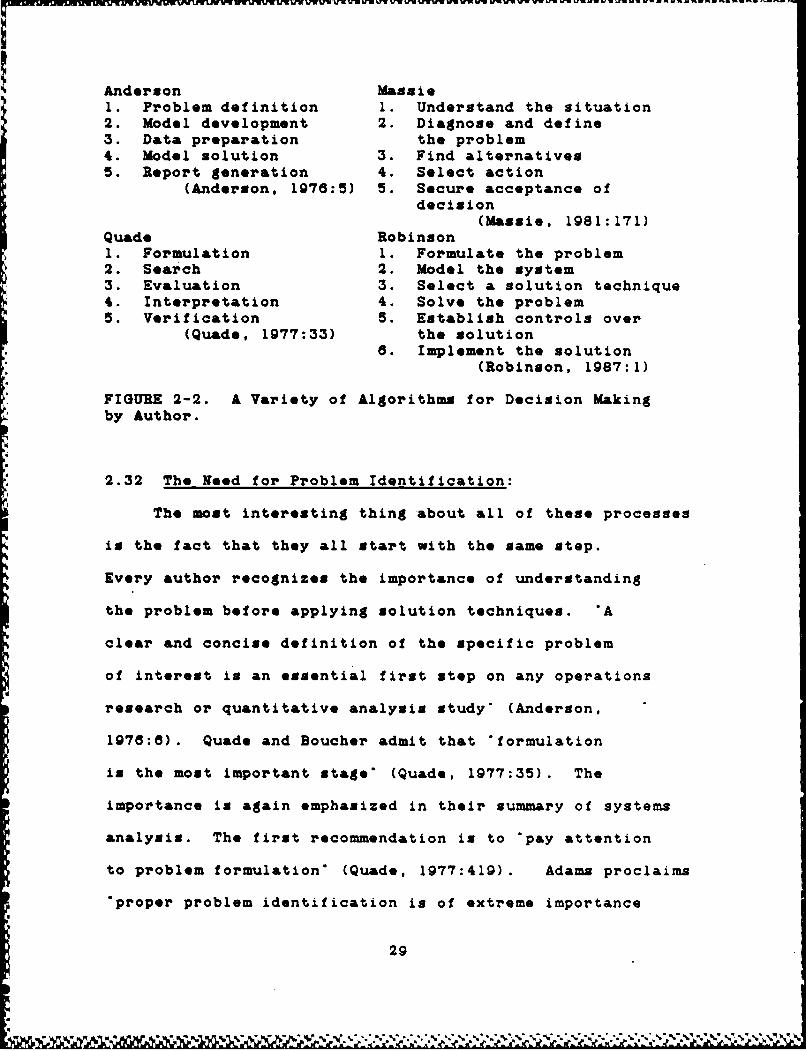
Anderson Mdelpn1. Problem definition 1. Understand the situation2. Model development 2. Diagnose and define3. Data preparation the problem4. Model solution 3. Find alternatives5. Report generation 4. Select action
(Anderson, 1978:5) 5. Secure acceptance ofdecision
(Massie, 1981:171)Quad* Robinson1. Formulation 1. Formulate the problem2. Search 2. Model the system3. Evaluation 3. Select a solution technique4. Interpretation 4. Solve the problem5. Verification 5. Establish controls over
(Quad., 1977:33) the solution6. Implement the solution
(Robinson, 1987:1)
FIGURE 2-2. A Variety of Algorithms for Decision Makingby Author.
2.32 The Need for Problem Identification:
The most interesting thing about all of these processes
is the fact that they all start with the same step.
Every author recognizes the importance of understanding
the problem before applying solution techniques. *A
clear and concise definition of the specific problem
of interest is an essential first step on any operations
research or quantitative analysis study* (Anderson,
1976:8). Quade and Boucher admit that *formulation
is the most important stage' (Quade, 1977:35). The
importance is again emphasized in their summary of systems
analysis. The first recommendation is to 'pay attention
to problem formulation' (Quade, 1977:419). Adams proclaims
"proper problem identification is of extreme importance
29

in problem solving. If the problem is not properly
isolated, it will not be properly solved' (Adams, 1986:22).
This proclamation was based on the fact that information
is either inadequate or misleading.
Massie and Douglas also support the need for problem
identification by calling for an explicit statement
of the problem. *Since it is impossible to weigh all
the facts, the manager must develop a means of sifting
out the relevant ones (figure 2-3). In the classification
of these facts, one can then define the problem. The
more completely the problem can be stated, the easier
the othLr steps will be" (Massie, 1981:173).
Aviod traditional response
>Liaiin FactorsI
¶ ...... -- \_elevanceeand
Defie _____'Obstacles]
Problem L..
!iessesent,
Figure 2-3. Inputs to diagnosing and defining the problem.(Nassie, 1981:173)
To achieve the understanding of the required decision
process and criteria, the problem must be fully defined.
30
*WL ýA '-- 'ý '. -0 4ý:- %A ,.; -. '.P 'A7
"In a 'well formed problem' we know the initial state,
the goal state, and the operators. From these, we can
systematically generate all the intermediate states,
and hence we can theoretically develop a 'map' of the
entire problem space (Harmon and King, 1985:28)."
The field of OR presents hundreds of text books
and articles depicting detailed algorithms on how to
solve problems. Unfortunately this author has not found
any algorithms on suggested problem definition or problem
diagnosis procedures. Yet, every text or article dealing
with the process of analysis lists the 'problem formulation',
problem definition', or 'problem diagnosis' as the
first step.
2.33 The Art of Problem Definition:
If it is as important as Anderson, Quade and others
believe, why then has it been so hard to develop a procedure
of problem definition? Masaie and Douglas put forth
the argument that problem diagnosis is an art. They
give the example of a patient going to the doctor with
a stomach ache. The doctor just doesn't record stomach
ache. He performs an examination to find the cause
of the ache. Once the cause is found, he prescribes
the approved treatment for the cure. The same is true
of the decision maker. He/she must not be distracted
with Just the symptoms but search further to find the
31
Nk

cause. This is the art.
"The diagnosis and definition of the problem is
a recurring process. Reassessment and reconsideration
of the issues help keep the decision-making process
realistic and in touch with & changing set of conditions'
(Massi*, 1981:173). Thus, what we need as decision
makers is an art lesson and the tools to perform the
art. Like a painter, the decision maker must learn
to use the tools that spread the paint. Then he must
practice and develop insight to make the canvas come
alive with a correct problem formulation.
2.34 DSS and Problem Definition:
Not only is this chapter concerned with the manual
process of decision making but the automated support
for the human as well. These decision support systems
require even more explicit problem definitions because
tf the need to design the system. 'Decision support
requires a detailed understanding of decision making
in organizations. A descriptive framework provides
the basis for prescriptive design; that is, to 'improve'
*, a decision process, one must first define and analyze
it' (Keen, 1978:81).
Based on this need for problem identification,
a process for performing the task must be developed.
The process must be simple, flexible and easily applied
32

to any problem space or domain.
2.35 Requirements for a Capturing Process:
To capture the factors of a problem so that its
problem space can be identified, described, and bounded
calls for a diagnosis. This diagnosis must discover
several facts about the problem so that the remainder
of the decision process is enhanced.
Massie and Douglas describe a good diagnosis as
one which has both 'the reasons leading up to the need
for a decision and obstacles standing in the way of
achieving the objectives. A diagnosis consists of a
search for symptoms. The search must be based on a
clear recognition of the desired results, the obstacles
faced, and the limits within which a solution must fall*
(Massie, 1981:173).
Another way to describe the problem space is to
define it in three dimensions. Bartee describes the
problem solving space by looking at the problem taxonomy,
problem solving modes, and problem process. The problem
space is sketched with regard to personalization, col-
Tsboration, wnstitutionalization, and sonialkizeton.
Them* aie the ways Battensaeea the deiionon maker developing
the ability to solve problems. Kiss judges from his
observations that "we are now between the second and
third phases. Where we use conceptual frames for pre-
33

scriptive types of problem solving, combined with experi-
ences, but involving some behavioral aspects* (Edwards.
1984:14-15)
Just as the other steps of the decision process
are iterative and recurring. so is the diagnosis or
problem definition step. An the decision maker progresses
through the sequence of steps to produce the decision,
s/he must continually reassess and reconsider the issues
of the problem. This reassessment keeps the decision
process "realistic and in touch with a changing set
of conditions* (Massie, 1981:173).
Based on this need for problem identification,
a process for performing the task must be developed.
The process must be simple, flexible and easily applied
to any problem.
2.36 Conceptualization:
Of all the cognitive processes mentioned and discussed
in this chapter, the key to understanding how a capturing
process would work is conceptualization.
Conceptualization, or the process by which one
has ideas, is the decision maker's ability to create
concepts in the mind and link them together into a framework
of understanding. *This process is a key one in problem
solving, since the more creative concepts you have to
choose from, the better* (Adams, 1988:7).
34
' C

Conceptualization is not monolithic, but has many
and varied 'levels of conceptualization'. Each level
contains a set of linked concepts. Each set of concepts
is a layer that can and does have links to other layers.
The layers at the top levels are very abstract and free.
Those levels of conceptualization may address a variety
of problem spaces and even range across several domains.
The lower the level of conceptualization, the greater
the increase in detail and the more focus applied to
the problem space. The level of conceptualization becomes
more explicit and resides with the tiniest details of
a problem space.
2.40 Good Decisions:
If a decision maker understands the levels of conceptual-
ization inherent in the problem and completes an explicit
diagnosis of the problem space, then a 'good decision'
is more likely. 'A good decision depends upon the maker's
being consciously aware of the factors that set the
stage for the decision* (Massie, 1981:171).
Nothing is more elusive than the evaluation of
a decision as to its quality. What is meant by a 'good
decision'? Is a good decision different than a good
outcome? If so how?
Before delving into problem definition process,
a short detour discussion of 'good decision' is necessary.
35

This detour will offer a definition of 'good decision'
so that the decision maker known what to strive for
in the decision making process.
The first definition comes from the field of decision
analysis. 'A good decision is one based on the information,
values and preferences of a decision maker. A good
outcome is one that is favorably regarded by a decision
maker* (Matheson, 1968:24). Although a decision maker
has no control over the final outcome, he does have
control over the decision. Therefore as Howard puts
it "...making a good decision is only doing the best
we can to increase the chances of a good outcome' (Howard,
1973:63).
Based on this discussion, a 'good decision' is
one where the decision maker tries to obtain the desired
outcome using the most effective and efficient means
available. S/he does this by identifying the possible
outcomes, and then using all the tools available to
act in a way that increases the chance for the desired
result. These acts and their sequence then is a 'good
decision'.
A decision maker's problems are not trivial. All
complex problems require some form of human judgement
and cognitive processing. The human needs support when
s/he is overwhelmed by the requirements of the decision
task. A decision maker is vulnerable to a decision
38
task when the rate at which s/he must do the task exceeds
his/her capacity, or his/her ability to think is insufficient
to the task at hand. Theme are the problems where any
decision maker needs help. Theme are the situations
which call for decision support.
2.50 Decision Support Systems:
Because decision makers do become overwhelmed by
their decision task, they need some type of help or
support. Decision support systems offer a means to
aid the decision maker. 'Decision support implies the
use of computer hardware and software to:
1] Assist managers in their decision processin semi-structured tasks.
2] Support, rather than replace, managerialJudgement.
3] Improve the effectiveness of decisionmakingrather than its efficiency.'
(Keen, 1978:1)
However, the use of a computer is not absolutely necessary
for the system to be classified as a DSS (Keen, 1978:58).
2.51 Value of DSS:
For a system to be a real value to the decision
maker it must provide him/her with effective support.
The design of the system must reflect an understanding
of the management decision process. The manager, on
the other hand, must clearly recognize the criteria
for developing the aid and power of the resulting output.
37
"t 'A V
*Perhaps the most practical aspect of the DSS approach
is that it allows managers to initiate, design, and
control the implementation of & system. That is, a
DSS is built around a decisionmaking task and while
the technical issues may be extremely complex, the main
focus is managerial' (Keen. 1978:13).
2.52 Efficiency ve Effectiveness:
Since every human strives for the highest success
possible, he'll search for the best decision possible.
This search for the best decision will soon become a
trade-off between efficient and effective decision making.
These two terms become essential in understanding what
a DSS is to provide to the decision maker. 'Efficiency
is performing a given task as well as possible in relation
to some predefined performance criterion. Effectiveness
involves identifying what should be done and ensuring
that the chosen criterion is the relevant one.* (Keen,
1978:7)
In providing support to a decision maker, trade-offs
may have to take place. A decision maker does not have
the time for all possible alternatives to be enumerated
and evaluated in light of their effects on the outcome.
The decision maker is constrained by time, money and
the ability to comprehend. The support system must
also be efficient in the presentation of the information.
38
fI.F|~' V ~ %V% v

The aid should concentrate on the most pertinent information
and present it in & clear concise manner that will not
interfere with the decision maker's cognitive proces-
ses. 'Defining effectiveness requires & detailed under-
standing of the variables that affect performance' (Keen,
1978:10).
2.53 Perceptions Inherited by the DSS:
Keen and Scott-Morton go on to claim that the key
question for anyone building a DSS is: 'What specific
decision or decision process are we trying to support?'
When building a DSS, the designer must realize the
decision is not static but constantly changing. His
perception of the problem and the values s/he places
on the various outcomes continually change over time.
Thus the decision maker is facing a complex problem
that cannot be fully automated nor reduced to an automatic
choice. *This perspective requires the development
of methodological tools to examine the key decisions
of managers and to define the information that can or
should be made available to them. It suggests that
for a manager's information system, one should start
from his/her decision making activities and mesh the
system into the user's problem and needs (Keen, 1978:58).'
Scott- Morton recognizes that all managerial decisions
have two parts involved in the task. By evaluating
39

the task we should identify the key decisions it involves,
and then identify the parts of the process that seem
structured and which require human Judgement (Keen,
1978: 11)
2.54 Concept Mapping:
In this thesis effort a new tool for the decision
maker is presented. It is designed to meet the requirements
for capturing the problem space. By identifying the
key factors and ideas of a problem space and representing
their relationships to each other, the problem will
be identified and described by a map of the concepts.
The individual elements or tasks used in making a decision
will be identified and defined by repeatedly mapping
the user's or users' preception of the decision process.
This tool is concept mapping (CM). CM is taken
from the cognitive theory of education. "Concept maps
work to make clearly evident to both students and teachers
the small number of key ideas they must focus upon for
any specific learning task* (Gowin, 1982:11-2). Used
in this context, concept mapping becomes a "technique
for externalizing concepts and propositions' (Gowin,
1982: 11-3).
Concept Mapping is proposed to help the decision
maker better understand the problem and limit the problem
space. It is a communication tool that helps decision
40
makers depict relationships between concepts and lend
agreement to those relationships. Thus, a decision
maker can fully map out his perception of a problem
and view it in a variety of ways. However, the greatest
power of this tool lies in human inconsistencies and
variable perceptions. As the decision maker works on
a problem, time and changes in the environment help
to change his perceptions. If he has used the tool
and made his maps, he can review them and see changes
and consistencies in perception. This comparison of
maps (overlaying) is expected to greatly aid the decision
maker in problem diagnosis.
2.55 The Problem Definition Process:
Just introducing concept mapping as a tool for
decision makers is not enough. The tool and its use
must be shown to the decision maker as an integral part
of a process. This process establishes limits on a
problem space and defines the problem explicitly. The
application of concept mapping is tied to an entire
problem definition process. This process is not to
be taken as the only possible process of problem definition
but is an approach to help lend structure for a completely
unstructured arena. The direct application of the problem
definition process will be demonstrated best in the
adaptive design of decision support systems. (chapter-5.)
41

2.5G Why is it important to know and define the Kernel?:
As mentioned earlier, DSS requires an explicit
definition of the problem and the decision process that
solves that problem. Without the information there
is no basis for the design and no method of determining
the effectiveness of the system.
The kernel is a key decision element within the
decision process. It provides a starting point for
design of the DSS. Its discovery is based on the ability
of the designer to identify it among the many other
concepts and possible kernels, and the current perception
of the designer as he searches the decision process.
Given more than one kernel available in a decision
process, an evaluation of which kernel to use in the
p design of the DSS can be made. The kernels can be compared
based on a variety of constraints. The most common
constraints are technology, cost, time to develop, the
designer's expertise and the user's perspective.
Once the kernel is chosen for the DSS, the impact
on the final product is as important as laying the corner-
stone of a building. Changes can be made during the
development, but the direction and emphasis is set.
For this reason alone, the discovery of the most appro-
priate kernel of a decision process is paramount for
. the DSS's success.
42

2.80 Conclusion:
This chapter has introduced the world of the decision
maker in terms of the environment and the requirements
s/he has for defining a problem and identifying the
kernels of a decision process.
The remainder of this paper's purpose is two-fold.
First, it brings greater understanding to these cognitive
processes of problem definition and kernel identification.
Second, it introduces, demonstrates and evaluates a
tool and procedure that aid these cognitive processes.
43
43
.q `• . --- v-`v .•W ` -•\-*•\*-

Chapter 3
Concept Mapping
3.00 Introduction:
This chapter explains concept mapping through a
series of discussions. The first set discusses four
topics which describe and contrast a variety of cognitive
modeling schemes. The first topic defines concept mapping
according to its educational derivation. The second
topic is an overview of the various cognitive knowledge
representation models. The third topic explores the
differences between the goals, purposes and abilities
of the models. Finally, key definitions of concept
mapping are presented as it applies to the problem definition
process.
The theoretical basis supporting concept mapping
is briefly introduced in the second set of discussions.
Three theories are presented which give insight into
the mind's function. These theories are then supported
by a series of observations and views taken from various
researchers and their findings. Finally, a summary
of justifications for concept mapping is offered.
3.10 What is Concept Mapping?
This discussion overviews several topics. The
first topic is a description of the concept map as seen
44
and developed by educational researchers. The second
discussion reviews the various knowledge representation
systems. Finally, the information presented is summarized
and a combined definition of concept mapping is offered.
This final definition of concept mapping is from the
view point of applying concept mapping to the realm
of problem definition.
3.11 Concept Maps - Educational Derivation:
A concept map is two or more concepts that are
linked to each other depicting a meaningful relationship.
Concepts are objects or events which are assigned a
semantic label. Dog, chair, and raining are all examples
of concepts. The linking words are generally the verbs,
but adjectives, adverbs, prepositions, and sometimes
nouns can also link concepts in meaningful ways. When
a map is drawn showing its relationships, the result
is a schematic device that represents a set of concept
meanings embedded in a framework of propositions (Gowin,
1982:2.1).
"Concept maps are intended to represent meaningful
relationships between concepts in the form of propositions.
Propositions are two or more concept labels linked by
words in a semantic unit. In its simplest form, a concept
map would be just two concepts connected by a 'linking
word' and forming a proposition..* (Gowin, 1982:2.1)
45
SfAN iJ -Wk.LAMiZAZ*JŽ.

Concept maps are very successful in providing three
benefits to the user. These benefits are 1) identifica-
tion of the small number of key ideas within a subject,
2) a visual road map showing the conceptual journey,
and 3) a schematic summary of the cognitive domain
of interest. These are powerful tools that aid a user
in translating understanding of a subject to another.
Concept maps are also very informative in their
design. As they are constructed, a hierarchy is set
up among the concepts. This hierarchy is dependent
only upon the builder's understanding or meanings that
s/he wants to show in the relationships of the concepts.
*. Based on this hierarchy, the embedded meaning of the
relationships and the arrangement of the concepts give
a specific meaning to the subject matter or domain.
One way to look at this function of concept maps is
to look at the way a subject matter is organized for
teaching. *Since meaningful learning proceeds most
easily when new concepts or concept meanings are subsumed
under broader more inclusive concepts, concept maps
should be hierarchical. The more general, more inclusive
concepts should be at the top of the map, with progressively
more specific, less inclusive concepts arranged subord-
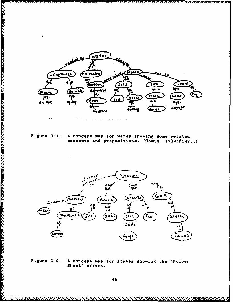
inately" (Gowin, 1982:2.2). Figure 3-1 shows a represent-
ative concept map. This map show the meaning relationships
between each of the concepts as well as the hierarchical
46
-- NJOA A-- .*J -L L a.,

relationship.
One more very important function of concept maps
is their flexibility. Depending on the user's view
of the concepts and their relationships the superordin&te-
subordinate relationships will change. Concept mapping
allows the user to *pull up' a subordinate concept to
a superordinate position and rearrange the relationships
to the other concepts. This function is called the
"Rubber-Sheet" effect. This is the same type of cognitive
function that occurs in the mind and results in the
alternate meanings associated with objects and events.
Figure 3-2 show the same group of concepts show in figure
3-1, but the ordonnance has been changed to reflect
a new meaning or emphasis in the domain. Some of the
concepts have been dropped because they are no longer
necessary for the meaning that is being transferred
or negotiated. Also, some of the links have changed
to show different meanings.
Extrapolating all of these functions and definitions,
concept mapping is a technique for externalizing concepts
and propositions as they are organized in the mind.
Thus, a concept map becomes a forum or tool for two
or more individuals to negotiate meanings. This negotiation
of meaning is the basic purpose for concept maps in
education.
47
........ •.. ' "
concepts and propositions. (Gown, 1982:Fig2.1)
4 )-
Figure 3-1. A concept map for wtater showing tome relatedcoShepts effect.ton.(Gwn,182Fg2
48o
WO
£4,% * V~%%'~ V VJ % 5 ~V% *S, ~ ~0..S % W 9

3.12 Knowledge Representation Systems.
There are several knowledge representation schemes
derived by artificial intelligence research. Theme
include such tools as Semantic Networks, Extended Semantic
Hierarchical models, Entity-Relationships models, Object-
Attribute-Value triplets, Rules, Frames, and Logical
Expressions. Each of these tools have various advantages
and disadvantages depending on the user's needs. Below
is a brief description of each of these methods.
Semantic Networks - *A semantic network is a collection
of objects called nodes. The nodes are connected together
by arcs or links. Ordinarily the nodes and links are
labeled." (Harmon, 1985:35) The main advantage of this
method is its flexibility and ability to inherit meaning
from the relationships. Semantic nets are similar to
concept maps.
Extended Semantic Hierarchical Models - "The Semantic
Hierarchical Model (SHM+) is an example of a data model
based on semantic networks. SHM+ uses the abstraction
concept to form a hierarchical network." (Handgraaf,
1988:39)
Entity-Relationship models - Peter Chen defines
an entity as "a thing which can be distinctly identified"
(Handgraaf, 198e:21). He goes on to define the relation-
ship as "an association among entities' (Handgraff,
1986:21). A relationship can have many entities associated
49

with it. 'Works for* is a relationship of employees
to an employer. In that example there are many entities
in employees but only one in employer. *The 'role'
of an entity in a relationship is a function that it
performs in the relationship* (Handgraaf, 1986:21).
The Entity- Relationship model, is an excellent tool
for designing databases, but lacks the hierarchical
and inheritance functions found in SHM+.
ObJect-Attribute-Value triplets - Objects are either
physical or conceptual entities. Attributes include
the general characteristics or properties associated
with the entity. The value member of the triplet specifies
the specific nature of the attribute in a particular
situation. (Harmon, 1985:38)
Rules - 'Rules are used to represent relationships
and can be used'with many knowledge representation schemes.
One of the basic structures of rules follows an 'if
then' format. Given a premise has occurred or is true
then a conclusion is presented. (Harmon, 1985:42-43)
Frames - *A £rame is a description of an object
that contains slots for all of the information associated
with the object." (Harmon, 1985:44) Frames can hold
both declarative and procedural representation ol facts.
Thes6 are two different strategies that aid in building
and using relationships between entities.
Loglical Expression - There are a variety of logical
50
->
systems. Harmon and King summarize both Propositional
Logic and Predicate Calculus. Again these system establish
relationships between entities or objects through asser-
tions. Thus the assertion must be established as either
true or false.
All of these are schemes attempted to translate
meaning or understanding by using a variety of forms.
No one scheme is right nor wrong. Each scheme has its
specific area where it works better than another. But,
the key question is: Do they depict the relationships
between entities and translate that meaning? -Any meaning
representation system, either human or mechanical, must
make explicit exactly what the relationships between
concepts underlying a verb are. (Schank, 1U94:U9)
4.13 Differences between Concept Mappinf and other Schemes:
The technique of concept mapping is different and
unique from knowledge representation systems in three
ways:
I) The first difference is the goals of the systems.
Concept mapping is a knowledge acquisition method.
its main goal is to capture the understanding an expert
has about a problem. The acquisition process includes
both the conceptualization (the individual's perception
of the problem space) and solution or decision process
of the problem. The other systems described are knowledge
(a1
representation systems. The knowledge representation
system is an encoding process of facts and relationships.
'The 'Process' of extracting knowledge from an expert
is called 'knowledge acquisition', wbereas the 'procedure'
of encoding it in a program is called 'knowledge represent-
ation' and techniques to use this knowledge are called
'knowledge manipulation and retrieval''
2) The second difference between concept mapping
and these other schemes is the purpose of the methods.
Concept mapping's main purpose is to capture an individual's
understanding of a domain and then translate or negotiate
the meaning with another individual. The knowledge
representation systems are designed specifically for
relating meaning so machines can operate on the relationships
and conclude the same results as the human mind. There
is a difference in these operations of translating meaning.
That difference is locked in the understanding of the
concept 'understand'.
"The basic idea in understanding, whether by computer
or by people, is first to figure out what concepts are
being communicated and then to use those concepts to
help in figuring out what else might be the case. (nce
we know there was a 'giving' action we know that there
was a 'taking' and a 'receiving'; we know that there
was an object and that someone now has it and will probably
b2
use it for whatever it is normally used for. Ascertaining
this kind of information is what understanding in all
about- (Schank, lW84:hI).
J) The third difference lies in the abilities
of the systems. To properly capture the knowledge of
an expert, the tool must be able to reflect the cognitive
and affective functions of the mind. The tool must
be able to give multiple meanings and describe feelings
when necessary. All but concept mapping, SHM+, and
some semantic networks, are rather rigid in their structure.
They are not flexible. Therefore, it is less convenient
to represent multiple meanings between entities.
kandgraaf refers to the flexibility of a conceptual
model as semantic relativism. 'Semantic relativism
refers to the ability of the user to dynamically change
the way data and relationships are viewed within an
- application. If a model is to successfully move into
the realm of conceptual modeling, it should not restrict
the user to one view or another- Uandgraa&f, 198:0'7).
This flexibility function will also be described later
as two separate functions called 'progressive diffoetenti-
&tion" and 'integrative reconciliation-. Concept mapping
Shas the function of 'rubber sheet' that gives it the
* flexibility necessary to view concepts in different
meaningful relationships.
Uowln points to the need for cognitive modeling
4-
•.• , .. " -,•- -•-• • -.- .•-• • ,• -•..%.- .. . .. . .. ... , %o ."' .%. %. • . •.-

to describe feelings. Cognitive processes and memory
recall are tied to previous feelings or emotions. t'or
example, if a person thinks of a birthday party feelings
of joy, excitement, or anxiety may accompany the memories.
rTo capture the true relationship among a group of entities,
the emotions they invoke must also be captured. "These
new "cognitive science' models fail to connect thinking
with feeling, partly because the computer metaphor on
which they are based does not Involve feelings- (.owin,
IV82:1.8). Handgraaf also points out the importance
for concept models to capture the behavioral aspects.
The definitions presented below define concept
mapping with respect to its application in the problem
definition process and its goals, purposes, and function-
&it•y described above.
A Concept Map is % tool of knowledge acquisition
that translates and negotiates meanings between individuals.
Concept Mapping is the process of knowledge acquisi-
tion that captures an expert's conceptual structure
of a problem.
J.20 The Supportingi Theory of Concept Mapping.
This discussion presents three basic theories e±
the human mind and how it stores and retrieves information.
Each of these theories are very similar, yet come from
three different fields of study. All the theories lay
54

the saMe basic foundation for concept mapping. rThe
first discussion describes the current theory of how
the mind physically works using the "Knowledge-line
or K-lIne' idea. Cognitive psychology offers the schema
theory and shown its application to learning. T'he third
discussion presents Ausubei's theory of cognitive learning.
Following these descriptions are several views and obser-
vations on conceptual structure. All of these theories
and views combine to show the functions of the human
mind. based on this understanding of the mind, concept
mapping is introduced as a means to capture (acquire)
the knowledge in the human mind in an efficient and
effective manner.
3.21 Theory of Memory - Knowledge-lines:
Minsky proposes the theory of -The Knowledge-line
or K-line" as a theory of memory. "Whenever you 'get
a good idea' solve a problem, or have a memorable experience,
you activate a K-line to 'represent it'. A K-line is
a wire like structure that attaches itself to whichever
mental agents are active when you solve a problem or
have a good idea.' (Minsky, iW80:82)
Kenneth Haase, a student at the MUT artificial
intelligence laboratory, gives an interesting analogy
of K-lines. In the following story, he redefines the
K-line In terms of colors and demonstrates their function.
"You want to repair a bicycle. beforeyou start, smear your hands with red paint.Then every tool you need to use will end upwith red marks on it. When you're done, justremember that red means 'good for fixing bicycles."Next time you fix a bicycle, you can save
time by taking out all the red-marked toolsin advance.'
"if you use different colors for differentjobs, some tool will end up ma,%ked with severalcolors. That is, each agent can become attachedto many different K-lines. Later, when there's.a job to do, just activate the proper K-linefor that kind of job, and all the tools usedin thi past for similar jobs will automaticallybecome available." (Minsky, lWSU:82)
based on K-line theory, human minds are filled
with chunks of agents that are connected by the same
K-line. When humans remember, the K-line reactivates
the connected agents and creates the idea. If the agents
were a solution to a problem and a Similar problem is
*' encountered, then agents of the first problem may be
activated as possible solutions to the new problem.
The ideal performance of the mind would then select
the most appropriate agents necessary to solve the problem.
This results in establishing new K-lines for the second
problem, and tying agents to more than one A-line.
The K-line concept is expanded by the "Level-band"
theory. This is basically the way the mind links agents
at different levels of stýength. 'We learn by attaching
agents to K-lines, but we don't attach them all with
equal firmness. Instead, we make stronger connections
at a certain level of detail, but we make weaker connec-
-,
%.v••t.•.v*;''.''.'',•'.':..'-'.%-.%*%'%'%. .. -.-. .. f.." "" " /%\•*" "" " " -"""" ""S"" ""
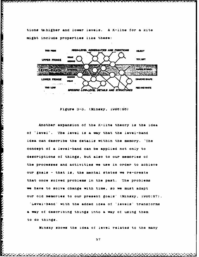
tions tahigher and lower levels. A K-line for a kite
might include properties like these:
uppa Fnimat W IMFml4 a-rr
UPV E ; 4ANGE m
LOWIM FRINGE9 OPACO &V
ITOOLOW % W•IMYSllIfUaM-.LOW4.dVU OITAIJ ANDE STRURES
Another expansion of the K-line theory is the idea
of 'level'. rhe level is a way that the level-band
idea can describe the details within the memory. -The
concept of a level-band can be applied not only to
descriptions of things, but also to our memories of
the processes and activities we use in order to achieve
our goals - that is, the mental states we re-create
that once solved problems in the past. The problems
we have to solve change with time, so we must adapt
our old memories to our present goals' (Minsky, IW86:87).
"Level-band" with the added idea of 'levels- transforms
a way of describing things into a way of using them
to do things.
Minsky shows the idea of level relates to the many
• '1

ways a human thinks. He goes on with the discussions
by examining the fringes of the levels. If the level
of detail about an object is too detailed (lower-band),
then it will prove to be too difficult to relate the
ideas to new situations. Consequently, if the level
of detail is too lax (upper-band) then the goals will
not be within reach of the situation.
N K PAM•' $TWO K $ArM
K-Me atahe t nny agenta K-/I.attached te eK4Inea.
•isiure •.-4. K-Line Attachments. (Minsky, lU•O:UU
Another function o -ne18te ability t
tie to other K-lines. (See figure •-4b) Ihis saves
the mind from having to connect K-line to all pertinent
agents. Mut there is a cost in making these connections.
"Our trick of connecting new K-lines to old ones will
not recapture so many of the scene's precise, perceptual
details. Instead, the kinds of mental states that ths
"hierarchal' type of memory produces will be based more
OUT
on stereotypes and default assumptions that on actual
;Kh
* perceptions. Specifically, you will tend to rememberZ ' ,g ' - . -

only what you recognized at the time. So something
is lost - but there's a gain in exchange. These "K-.Line
memory-trees' (see figure 3-b) looses certain kinds
of details, but they retain more traces of the origins
of our ideas. ... the structured memories will be much
more easily adapted to new situations.- (Minsky, l•8:8W)
K K
11" MH "o Umum ISO! PAPImR S 5f110 TCK&
Figure J-b. Memory Trees. (Minsky, l~ad:WU)
one last idea proposed by the level-band idea is
the way humans manage the levels. This management can
be thought of as organizing ideas. Figure 3-0 shows
two ways to organize the objects bird and piane. Note
that both hierarchieg represent the links between the
things. Neither knowledge-tree is more correct than
the other. They are just two representations of managing
ideas.
blb
dtI
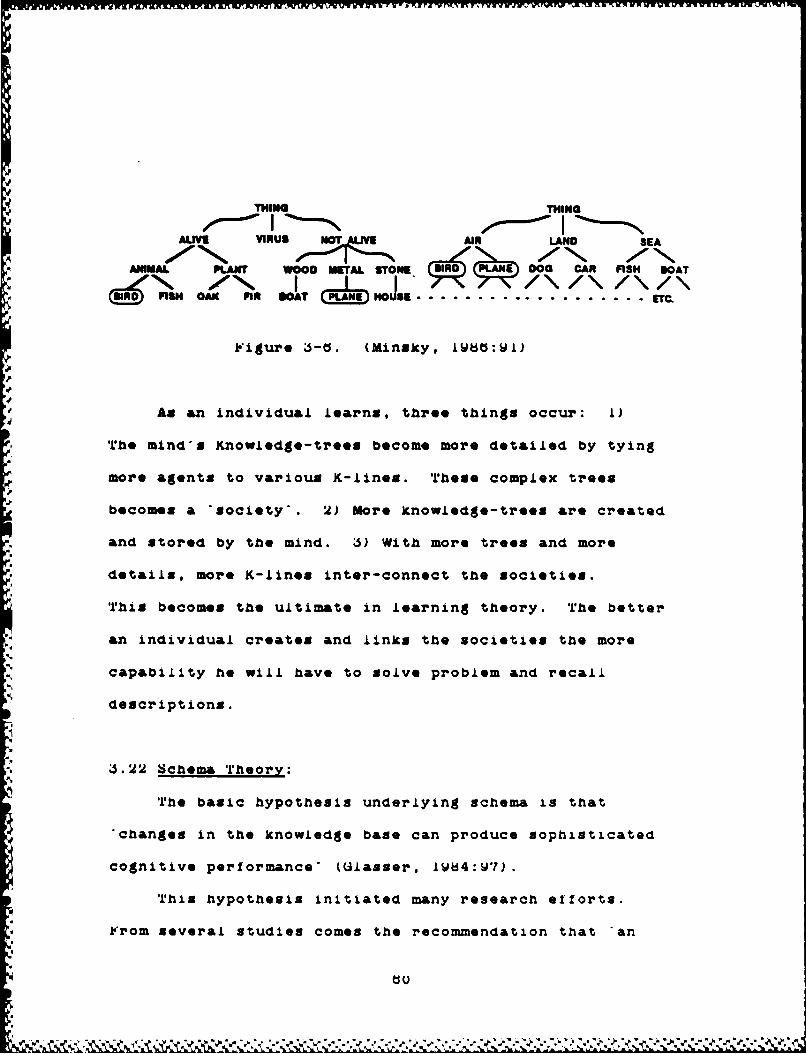
THIN THING
ALIVE VIRUS AIR LAND SEA
ANMAL PLANT WOOD METAL STONE El DOG CAR FISH DOAT
( ,,)FISH OAK FIN GOAT IN So . .O.S. ................ . T
JFigure 3-0. (minxxy, iwats:wi)
As an individual learns, three things occur: 1)
The mind's Knowledge-trees become more detailed by tying
more agents to various K-lines. These complex trees
becomes a 'society'. 2) More knowledge-trees are created
and stored by the mind. ý5) With more trees and more
- •details, more K-lines inter-connect the societies.
This becomes the ultimate in learning theory. The better
an individual creates and links the societies the more
capability he will have to solve problem and recall
*descriptions.
4S.22 Schema Theory:
The basic hypothesis underlying schema is that
"changes in the knowledge base can produce sophisticated
cognitive performance- (Ulasser, 1W84:17).
This hypothesis initiated many research efforts.
From several studies comes the recommendation that -an

important focus for understanding expert thinking and
problem solving is investigation of the characteristics
and influence of organized knowledge structures acquired
over long periods of learning and experience- (&lasser,
tV84:Wb). This recommendation was also made by Minsky
and P&pert. In the mid 70's, the emphasis of artificial
intelligence changed from a power-based strategy of
thinking to a knowledge-based strategy. This change
was supported by the theory that intelligence was a
function of knowledge organization. 'A very intelligent
person might be that way because of specific local features
of his knowledge organizing rather than because of global
qualities of his thinking- (Ul&sser. 1l84:Ud).
Schema theory is based on the idea that the human
mind stores knowledge in structures. if the mind does
store knowledge in this manner, then there ought to
be ways to determine the organizational patterns and
represent them to other individuals. 'Schema theory
attempts to describe how acquired knowledge is organized
and represented and how such cognitive structures facilitate
the use of knowledge in particular ways.
A schema is conceived of as a modifiable information
structure that represents generic concepts stored in
memory. Schemata represent knowledge that we experience
interrelationships between objects, situations, events,
and sequences of events that normally occur. In this
'U

sense, schemata are prototypes in memory of frequently
experienced situations that individuals use to interpret
instances of related knowledge" tUlasser IW84:lUU).
Using the scaema theory, educational researchers
have applied the ideas to learning and teaching. To
apply this theory to teaching required the development
of several important teaching principles. "Iýrst, one
must understand an individual's current state of knowledge
in a domain related to the subject matter to be learned,
and within which thinking skills are to be exercised.
Second, a 'pedagogical theory' can be specified by the
teacher that is different from, but close to. the theory
held by the learner. Then third, in the context of
this pedagogical theory, students can test, evaluate,
-and modify their current theory so that some resolution
between the two is arrived at' (Ulaser iLd4:iUi).
The basic pedagogy for schema is to develop lessons
and experiences which enable learners to build, test,
modify, and retest these cognitive structures. This
process relys ver)A heavily on the ability to capture
the student's structure. Thus, learning, or knowledge
acquisition. is the development of these structures
in the human mind.
;5.2J Ausubel's Theory of education
The two previous theories set the scene for a discussion

of Auaubel's theory of cognitive learning. based on
similar understandings of the human mind proposed by
Minsky and UlA&sser, Ausubel developed the cognitive
theory of learning. There are five major components
to this theory and all are listed in figure J-7.
J.24 Supporting Points of View:
The above description of how the human stores
information is supported by an observation of Roger
Schank who is working in the artificial intelligence
field. Ne is explaining the idea that concepts must
be linked to previous knowledge. 'We understand what
we read by adding It to what we already know; a new
meaning is always & product of a previous meaning.
Understanding a sentence involves all the knowledge
we have so far acquired about what goes on In the world.
The more knowledge we have about the world, the more
experiences we have had, the better equipped we are
to find possible meanings for whatever sentence, paragraph,
poem, or story might come our way. Language is not
in itself knowledge, but it In a medium for expressing
and organizing what we think we know, which is really
only what we believe or feel at a given time. When
we are saying to ourselves, 'whoever wrote this sentence
has some knowledge and this sentence must be his or
tj j

Ausubel's Cognitive Theory of Learning
Key Concepts
Meaningful Le&rnintA learner consciously and deliberately links new
knowledge with relevant concepts s/he already knows.
Note LearningThat which occurs when a learner makes no deliberate
effort to relate new knowledge to concepts the learneralready has.
hierarchically OrganizedCognitive structures have more inclusive, more general
concepts an prepositions superordin&te to less inclusive,more specific concepts and propositions.
?rogressive DifferentiationConcepts in cognitive structures undergo progressive
dlfferentiation- wherein greater inclusiveness and greaterspecificity of regul&ritles in objects or events are
discerned and more propositional linkages with otherrelated concepts are recognized.
Integrative Xeconcili&tionThis occurs when two or more concepts are recognized
as relatable in new propositional meanings and/or conflictingmeanings of concepts resolved.
'Igure J-7. Ausubel's Key Concepts. (Uowin, IWU2)
her attempt to communicate this knowledge ' bhank,
Shank's second observation deals with the definition
of events or objects. He looks at concepts as linked
by action verbs. Using this definition each concept
g&ins I's Identity by the combination of actions used
to describe it.

"We tend to See the world in terms of the events
that take place in it. These events usually involve one
or more actions, which we describe using the many verbs
in our language. We can think of concepts which don't involve
actions, such as a fine spring day, or & rock, or a fire
hydrant. It's easy to say that a rock doesn't perform actions
because it just sits there and doesn't move. But we have
to stop and remember that the descriptions *Just sitting
theree and 'not moving' both refer to actions.
It is extremely difficult to describe an event without
describing actions as well. We can say the words 'rock'
and 'fire hydrant'. but somehow the word 'rock itself
doesn't tell us much about rocks. We have to use other
words. A fire hydrant means the sent of actions that are
called up when there is a fire. It refers, in an implicit
way, to the need to stop fires from destroying objects by
soaking those objects with water. If we want to describe
a fire hydrant in a useful way, we must do so almost entirely
in terms of actions. What can one do with a fire hydrant'
What comes out of a fire hydrant'? What's it made of"? What's
a f•ire The actions involved in the concept of a tire hydrant
are discrete and unique in that they differ from those involved
in the concept of a telephone or and electric drill. (Sthank.
A184:WU)
Another observation about the function ot the mind
comes from professor L.bob Uowin. As an educational researcher.

determining how the mind functions is key to being able
to develop effective teaching/learning methods. he also
supports these theories as reflected in the following obser-
vations.
"Uur minds seem to work "hierarchically' as a mosaic
of interrelated concepts, but instruction is necessarily
linear in form. We must present knowledge segment A, then
segment U, then segment C and so on. Concept maps can help
us to organize the whole set of concept-propositlonal relation-
ships we wish to present, but then we must still reduce
this organization to some sequence of topic A, topic d,
-* topic C, and so on. Concept maps do not specify the exact
sequence for presentation, but they do show hierarchies
of ideas and thus suggest psychologically valid sequences
J.JO Why Concept Mavving'!:
S.l'rh The power of Concept Mapping:
Ausubel's Dictum: The most important singlefactor influencing learning Is what the learneralready knows. Ascertain this and teach him accor-dingly (Uowin, LWU•i: 12).
in order to get at what the student Knows, a tooi
or device had to be developed. This tool had to te 2lmp..
and functional in ascertaining what the learner Knows.
Ausubel present•ed the id*e ot cognitive maps. Uowin and
Novak continued this line of reasoning and implemented concept
mapping into a variety of teaching arenas. They found concept
mapping to be an invaluable tool for determining what a
learner knows. Concept mapping is an educational tool
that has been developed specilfically to tap into & learners
cognitive structure and to externalize for both the learner
and teacher to see *what the learner already knows'
Uowin contrasted the benefits of the concept map
against the outline. He found two distinct differences.
Yeirst. good concept maps snow key concepts and propositions
in very explicit and concise language. Second, good concept
* maps are concise and hence show the key Ideational relationsnip
* in a simple visual fashion' (Uowin, L~d2.4.i).
J..J Applyint Concept MaDvinA to the eroblem:
*ranslaltng concept mapping from an educational setting
to one of problem solving or decision making is not as drastic
as it might seem at first. ihe expert replaces the teacher.
SThe VS designer becomes the learner. but the concept map
taps the cognitive structure of the teacher instead ol the
learner. 'his creates a map of the knowledge structure
of the expert. It can then be used to translate and negotiate
meaning to the OSS designer. Unce tne OSS designer understands
the problem and the process no uses the intormation to develop
the decision aid. The map can also become a record o! under-
standing for future relerence.
based on the theories presented by Minsky, Lilass
and Ausubel, and the research findings from educational
research efforts, concept maps can depict tne expert's knowledge
base. *rho K-line theory tolls us that the knowledge organization
of a problem will be the agents used in defining and solving
it. Schema theory also supports this conjecture when appliec
to problem solving. rhe conclusion is that concept maps
created by the expert capture the key concepts of the problem
and/or the elements of the decision process used by the
expert.
*JJ R easons for Selecting Concept Mappint:
There is one final question to ask. is there another
tool that can capture the expert's expertise as effectively
as concept mapping' 'rhe only tools available are the xnowledge
representation systems discussed above. Inese are generally
not appropriate because they are representation systems
and not acquisition systems. it is possible to structure
SHM* into concept mapping format. but an altered SMM* woula
become concept mapping.
The other Knowledge representation models nave been
used in data base system to Snow relationshnps between data
elements. I'hey are very restrictive because ol tne need
to interact with machines. Tlhese models do not nave tne
buiit in tiexibility and hierarchical tunctions o: concept
tb

mapping. rhus, the process would lose semantic relativism
and ordinate meanings. 1'or these reasons concept mapping
is anticipated to be an ideal tool for capturing knowledge
from an expert.
J.4U Conclusion:
if the expert is really the expert in solving the
problem, then capturing the specific problem's aSentas
(concepts) and their appropriate 'K-lines' (links) would
capture the definition and decision process elements. With
this twist in its use, concept mapping becomes tne *asic
tool for acquiring knowledge from an expert.
'The next chapter te&ch*es how to do concept mapping
and explains some of the techniques required in holaing
a Knowledge acquisition interview.
%AIV%* V V. *..* *~. *

Chapter 4
'hoe Concept Mapping Technique
4.00 Introduction:
Learning the concept mapping technique is just
like learning any other skill. lhb student must start
by learning the terms and basic rules to the procedure.
Then s/he must practice, practice. and practice some
more. The skill of concept mapping has relatively lew
terms and rules. It is & simple, functional tool that
can be applied to & variety of learning or knowledge
acquisition requirements.
Concept mapping comes from the field of cognitive
education. A teacher who believes in the cognitive
structuring phenomena of the mind will use concept mapping
to introduce students to new concepts. The technique
is relatively new yet it is basic to education. Aii
0 the ex&mpies in this chapter are from the author a
background in applying concept mapping wni*e t&eacing
This chapter introduces the axilAi of concept mapping
&no conducting tne concept mapping interview ine :*Irst
parts ot tnis chapter toAiow iowin 5 strategy ?or trzP.:.-A
concept mapping to iearners rigures 4-. an: 4-, . st
&ai the steps in iowin s strategy !'mi esson s i7
two parts 'ne first part .ntroIices arts 3e: :nos týo
terms ot concept mapping ne main p-;rptse :-r "n.s
V ~ 4 ~ ~- -. * * * -- * J

A. Aseiw ei to huMMw f"r
1. 1111161 WAN Uae of W410111 Ma the blaCkhad" Or SvereaM P1GjeCtCe SWIM aUse of fasli~ userde for objects e asetber list foer so--s. Fogmnla. ObjPet Voel "t bat Mrt. dog. thair. tiree. aede. book. die
owaftede midU bee raisinga. pioplag. makbing. thiakIn., thimer.birthday perty. Ask ehL~deu Ut they earn describe how the 10m Uses differ.
1. Ask the ehbildem ts, describe Wdes thoy think *Iofthee they beaw the verdcar. 6eg. see. Selp them raeo~elve that ewesi thean% we see the sain words.esth of is my thick of senthiag a little dill erec. These metalinsigewe bhem IW vWe" a". met Ofeucteot Introduce the Word "Concept".
S. 010004 89IstiiieS 1s 02. 61.5mG SWeat Verde. AeSim, poist out the differeacave &ll have io evo mntal Leaguse ar cotto1 event*. Tom my wane toevwert at this point thee eam raesess we have troube WWerstindiag eachehetw emotions is thet our conept*e are easvo quite Identical evm thou"hme haer the sa ve me@. Warde or* labels for cemeoIts. but each of ws asetdeaequirs os m smmlage i doti.
4.Ra list wods o wat usov wuhere. the. Ise. thean, with, etc. Ash chLidteathoe come to their sids dentes they berseekh of tha.* veords. Thee* are setmavept werad e;u call tham Ij~a ewads and we am thoee is speaking andviitinge. Lithiag weerds we %aed together with concept words to consructsome moe that bove aset.
3. Pr"o smo e met concept words bet roethe noo ofseii people, ewents,places. or objects. te sum examine ead help childerve to ea" thel~instatlen between laobel for ruemLariteso Is awuato or ojects as couterestedto sPac ific ewents M objects Mr proper &Oman.
6. vias toe concept words en the boead eed Unities wads. Construct a fewskew t eautiess to Walstiree. hew concept words plus hLakina words are usedby btsso to comey uanding. Somles weald be: The dog is rumia~ig. Theream, else"and thleet *r etc.
7. Uso" the Studants costaruct a lew ohovrt sentence@ of theiu va ean Identifythe cescepe verd@. t ell theether eash is se ebject or ewee * sa &Iso Identifythe ILahiG words.
t1. It yea hoew biliaipea children to the delso, hUw. thee presenst gesfraiseworde that label the ons ronets or ojects. leLp the children recogalitethat language ees eat sies the mucopt; it waly soiees as the label we usater the coe"y. If us learn merd@ but fail to lawnr whet kind offlgoaisri , Les ojects or ovmses as e wrs epresent. go hare uast learned
9. luttudwee oem ohe bti voaa~l~jir mved to the clase suck not dire.tares. j1j0j. Thue. eve vers. that stoed fa ame concepts they alreadimeer but they hoe" onoafse specials minirgs. Gelp the children see thatseacepte do mct %me ruid t ined eveiala, "~t the nesias" cmn gero Odshow aso us ear, usr..
1S. Cbine a sectiea ad a tomibeak (.me paeg is eaflICIMZ) adduplicate Cop166far abilarve. Choose a reading passage thee ceamys adefinite moalas.40 a Clae. ae" thean to read the passage ead Identify ka coaepcay. Useually10 to 26 rolevset eaneopce .111 be round Is a giggle pags of text ustertal.Alae o the ebtidre Sets Sm h"AMIa 9e8de a concept UNITe that Ore1m lopewee: to the "Otery Lim'.
% % % %

Consists monies. Astiritiee
* -i. select a partioularly meanisgful parapaph er two fran a taut w otherprinted material. hrve the students roed the text sod selelct the 'key
* ~concepts." thee ise theseconceapts maeearov far aedeaetanding the ammringad the text. uset thoea camneepc& so the beard (Wor verhead prejoeter) *athey wre identifiled. Vow discuss with the students which Concept is the"Sat .mprtast, ant inclusive idas is the tome.
2. Pat the IMit inclusaive" Canept at the head of a sANN liat of "Taokordered" concept. List the next "weat gamrl"."mant irnclusive concept."workling through the first time until all ecepto are 'reaf ordered.'There will wat alwase be apreaeaot anang the studenst an the ordeTRSnbut usalaly anly a few major differences in cashing of the concpts &rim*.and this is 09; it sugests that there my be owe then .me Way to see themieaig of the text selection.
2. New begon emostructiag a concept wep. wealg the rash ordered list "n a goida4 Ito building the concept hierarchy. Nawe students help in choeas ag go"d
linking used@ to fwor tba-2Lrjtjana shown b the lion as the map. teegood way to practice mp asking to to hae"a tewt concept wordsand linking words on paper rectangles. aod then they can rearrang, thgea
- as they met -w lnIteigt M the miorsaftiastlo. I-(W~ flnure 2.9.)4. IMM lash far "CrasIOlaha" betwase"MCGIapto iS Coe section of the maP sad
emiaOptS ia another Pact of the Caseept "true." 3mwe StUdonta help tothen"e linhing werds fer the cross links.
S. Neat "first ef fert" sopa have poor symmitry or msam concapt clusters.poorly located relative to other mowe closely related concepts or c lutereOf conepts. 14canetruct the m, if this miold he helpful. Point out toatuddast that at least a" aod amiatine two cc theta reemastrwtrias ofa sop are mended to show a to"d repreaamtatla of propositional meanings
astheY vaderetand thin.G. Koecuaa the concept asp scoring criteria in Table 2.4 and "acer." the
Concept sap constructed. Foist out possible at.ucturl cheagee that mightiMprov the aseslag of the unp, and perhapa the mapa sew*..
7. Mass the studeat selact a sectlan of text or other meaerial and repeat antheIr am(or is graspa of 2 or 2) steps 1-6.
I. Student constructed mops can he presented to the class an the blackbboard wroverhead projector. or "reading" the Mo. it obo*id be eldear to otherstudents in the claaa Whet the text sectton wase about.
9. Name students construct a concept Sep for ideas important is a hobby. sport,orspecial interest area they have. These eight he posted *round the remadinformal discussion secouragad.
9.Incorporate me or two concept sopping "questions" in year next teat toillustrate that concept mopping ia a valid evaluetian procedure thatdawn"d hard thisking and am illustrate .erstanding ad the subject
Fi2gure 4-2. (Uowin, 1982:'Vabie 2.3)
lesson is to prepare the learner for the actual concept
mapping activity. The second lesson steps a student
through his/her first concept map. After this brief
introduction to concept mapping, the student is encouraged
to practice as much as possible.
Once the student has mastered concept mapping s/be
is ready for the interviewing session. rheo remainder
of the chapter explains the process used to concept
map the problem definition and decision process. Several
suggestions and rules-of-thumb are given. These sugges-
tions are based on personal experiences of over 100
hours of interviews and literature reviews of the inter-
viewing process. This portion of the chapter is not
in a lesson format, but will perform as teaching forum.
4.10 Learning How to Concept Map:
The following sections introduce the two lesson
plans. These lesson plans are generically designed
for any person interested in learning the skill.
4.11 PreparinA for Concept Mapping:
Attachment A is a self-paced lesson plan for any
student wanting to learn the basics of concept mapping.
Lesson A introduces the student to the following terms:
Objects Events Concepts
Linking Words Key Concepts
'I 1 ' .

4.12 Concept MappinX Activities:
A student who wants to learn how to construct a
concept map should follow the activities outlined in
figure 4-2. This lesson is designed to introduce the
student to the art of making concept maps. However,
to become proficient the student must practice and perform
the steps on his own. To gain the maximum benefit from
this sequence of lessons, complete the lessons in order
and then practice at every opportunity. A good practice
scheme is to concept map class lectures give by a teacher.
4.20 The Concept Mapping Interview:
The interview is a face-to-face meeting with the
expert. Its goal is to capture the expert's understanding
of the problem and his key decision elements. The interview
is the most significant part of the entire DS design
process because the information and perceptions gained
by the designer will be reflected in the final product.
The concept mapping interview is a process with
three distinct and. separate steps. The first step is
scheduling the interviews. Choosing the expert, informing
the expert about your needs, goals, and methods, and
making the appointments takes only a little effort but
pays big dividends. The second step is setting up the
environment for the interview. The expert and interviewer
both need to be able to communicate freely and comfortably.
"74

'rho last step in the process is managing the interview.
This section is designed specifically for the OSS designer
who will be using the concept mapping technique in defining
the problem and identifying kernels of the decision
process.
4.21 Scheduling the Interview:
The most important part of scheduling the interview
iS identifying and choosing the problem solver. Although
you may take on the role of problem solver, in most
cases this task will be handled by another individual:
someone who by experience or position has the unique
knowledge necessary to solve the problem or make the
decision. This person is the primary user that the
USS is intended for. This is an -expert-. An expert
is one of only a few persons who has special or unique
knowledge. 'by an expert we usually mean a person who
knows how to define problems and solve them. He knows
what facts or data to collect and investigate, he knows
what rules to use, and he knows how to make inferences
(Yandi, 1•~: 12) .
Selecting this person requires an evaluation.
First, learn as much as possible about the problem itselt.
Are there people currently solving this or similar problems'?
If so, who is considered the best at solving the problem"
Next make a list of possible experts in the problem
'7
domain. Then evaluate the list. Here are some criteria
that may be used in evaluating the list of experts.
1) Who do you as the LD)S designer have access to'?
2) What are the costs involved?
(e.g. Travel, Consultation 'ees, etc.)
3S) What are the available resources?
Unce the experts have been selected, they need
to be prepared for the interview. To prepare the expert
for the concept mapping interview, hold a meeting with
all of the experts at one time, if possible. At this
meeting brief the experts on the problem that you are
facing in trying to capture the definition of the problem
and identification of the decision process. Inform
the experts on the needs, goals and methods used in
the upcoming interview. This meeting sets the stage.
It gives the purpose for the Interview and tells the
expert what role s/he is to play.
The experts are better able to organize and communicate
their cognitive structures on a subject if they know
exactly what is needed and what are the goals. Experts
need to know a variety of different types of information.
Some of the questions to be answered for the expert
in this briefing are:
1) What kind of information is being sought•?
2) Which problem space are they to concentrate on"
.i) What is the process being used in the interview'
S.

4) How much time is needed from eact of them'?
5) What is the information going to be used for?
Answering these questions before attempting the interview
concentrates the efforts of the expert on the problem
"rather than on tie process.
This initial briefing also saves time. As den
points out the first interviews rarely have content.
He cites the time is taken in pleasantries, spouting
* motherhood', other general things, finding out 'What
the hell's going on round here', e*tc. (tden, lUb:b•i2).
To illustrate this point, all of the kCAAk experts
were briefed on the purpose and process of tie interviews.
SAfter introductions they were shown the basics of the
*, concept mapping technique. This was just a general
overview of the terms and an example of tow a concept
map is built. Unce they felt reasonably comfortable
* with the process, they were asked to concentrate on
their definition of XAAe and what they perceive the
decision process to be. Yinally, they were told what
the maps would be used for. They were now ready to
be interviewed.
Thie last thing to do at this initial briefing is
make the appointments. 'rhe time available and the desired
extent of detail in the maps, determines the number
of interview appointments made with each expert.
77

(enerally, three one-on-one interviews are best.
Mak*e individual appointments with each of the experts.
Do not attempt to interview two or more experts at the
same time. Experience has shown that one of the experts
will do the majority of the talking while the other
just agrees. interviewing two or more experts at the
same time does not capture the multiple understandings
that each has.
h•e first two interviews need to be relatively
close together in time. The first concentrates on the
definition of the problem while the second captures
the elements of the decision process.
The third interview session should have a considerable
separation in time from the first sessions. A good
separation would be anywhere from two to six weeks.
A shorter separation doesn't allow the expert's perceptions
to change very much. Separations longer than six weeks
Sgenerally are not suitable for either the expert or
the project. This separation enables the expert to
further think about the problem. As has been observed
in other concept mapping exercises, people change their
minds. Perceptions change because new experiences alter
old cognitive structures. This ins the natural process
of learning at work. There is more discussion about
the benefits associated with changes in perception in
Chapter b.
.U
'7

-%
The purpose of the third interview is to review
the maps that were constructed in the previous sessions.
The expert is given complete freedom to check over the
map and ensure that it still reflects his perception
of the issue. If x/he has changed his/her view of the
problem create the new or changed portion(s) of the
* concept map. Then, have the expert tie the new clusters
to the old maps.
Xach of the above interviews takes about an hour.
This is about the limit any expert or interviewer will
be able to fully concentrate. If the time resource
requires back-to-back interviews, breaks are a necessity.
Interviewers have limits. It is advised to schedule
no more than four to six interviews per day. This is
also recommended by Uowin; -four to six per day is all
that most people can handle and continue to be alert,
pleasant and thorough- (Uowin, Il82:7'-lS).
4.22 Setting-up the Interviewing Environment:
The preparation of the room and keeping records
is as important as preparing the expert for the interview.
kden insists on a particular room set up for his style
of cognitive mapping. in his review of a session evaluating
the problems of a publishing company, he cites one of
the nagging problems of a poor environment.
"The day was disappointing. The hotel provided
"% % % . . . . . .

rooms that were cluttered with formal furniture, we
had requested three rooms in which eight people Could
work in cramped conditions. The furniture was to be
easy chairs. What we finished up with were three rooms
of vastly different sizes-aLl too big, and with walls
cluttered with wall lights and fixed pictures. ... 6ecause
the environment was not as intended, it took me longer
to generate the right atmosphere than would have otherwise
been the case (Lkden A•WD:8A).
.ollowinS are a few of the ruies-of-tnumb for setting
up the Interviewing room for concept mapping:
L) Select a room where you and the expert can work
the entire session without interruption and limited
background noise. Heat, light and ventilation are just
as important as noise in considering the room.
) UObtain a chalkboard or dry marker board. It
these are not available use flip chart paper and suitable
markers.
5) Record the interviews. Audio tape is relatively
cheap, easy to manage,-and gives a record of the interview
in complete detail.
4) Uperate the recording machines with as little
interruption as possible. (i.e. Use L2U minute cassette
tapes.)
5) Obtain comfortable chair(s) and a table.
5.0
4.2J The Interview:
'ho interview is critical. Vonducted and managed
properly, the one hour session can return a bounty of
information. lbho remainder of this discussion is a
potpourri of suggestions and rules-of-tbumb. P-igure
4-4 lists some issues to consider while conducting an
interview. tVen though the Issues listed in figure
4-J are for conducting a clinical interview for educational
research, many of them directly apply.
To acquire the most information from the expert,
plan the Interview. tatablisa the purpose for the interview
and choose appropriate le&d-off qpestions for each main
topic. If the interview is to capture the decision
* process, ask a lead-off question that directs the expert s
thinking towards the decision process. ?or example.
the lead-off question may be: HOw Would you solve this
problem'
it is also important to prepare some follow-up questions.
However, don't fall into the trap of having to ask
all the questions on my list syndrome. Tnis becomes
boring for the expert and may reduce his openness toward
the interview.
WAIT! After asking a question, especially a lead-oft
question, wait. Studies show that teachers seldom wait
longer than 2 seconds after asKing a question before
they either answer it themselves or restate the question.
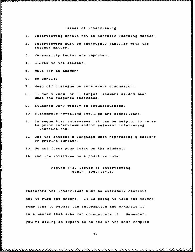
issues of interviewing
1. interviewing snould noft e Sora&tic 1'eacning Metnoa.
2. interviewers must De thoroughly t&miliar with thesubject matter.
S. kerson&lity factor are important.
4. LlS'rh. to the student.
S.Wait for an answer'
(. te cordial.
7. Heod off dialogue on irrelevant discussion.
b U. I don t know or 1 forgot answers seldom meanwhat the response indicates.
W. Students vary widely in loquaciousness.
1U. Statements revealing feelings are significant.
Ii. In sequential intervi*ws, it can be helpful to reoerto prior interviews and/or relevant intervening
instructions.
12. Use the students language when rephrasing q,extions
or probing further.
13. Vo not force your logic on the student.
14. tnd the interview on a positive note.
1igure 4-6. issues of interviewing(Uowin: i•U2: A6-Ad)
Therefore the intervieaer must be extremely cautious
not to rush the expert. it is going to taxe the expert
some time to recall the information and organize it
in a manner that 8/he can communicate it. hemember,
you're asking an expert to do one of the most complex
exercises for the mind to accomp,in Jive nim,•cr
time to respona
W•ILM' After waiting for the response. ma-e sure
you listen and understand what the expert in saying
Von t be afraid to rephrase the expert a statements
especially if you don t aee the tying reiationmnips
or understand the terms. me is the expert and you are
the learner. it a concept can nave more than one name
or label agree on the beat label as the interview progres-
ses. Much of the time, more than one label can Do used
to represent a concept. Choose one and maintain it
• "throughout the interview unless it is no-longer the
'* agreed Label.
As the expert starts to give the information, draw
the concept map on the board. rutting the maps on the
board allows both the expert and the interviewer to
see the map and discuss the concepts together.
Write ?AST' Don't let the expert think he has
to wait on you. tncourage him to talk at a normal rate.
hemember you're mapping only the Key concepts.
Don't worry about the clutter or neatness of the
map as you initially build it. There will be plenty
of time alter the interview to clean it up
Use either circles or rectangles to identify the
concepts. Draw in the Lines or arcs and pointers.
Label each arc with the appropriate linking words.
a8.
use the expert s terms as mucn &s poss..e JO aneac
and doev* ap z. usteru s maps a, t.It i a t.110 iav 1-110
expert is giving tne information ino re.aionsnops
tying thoes ciust*ers togeter wi, come out eventua..,y
it tre reoationsnips don t come out or you re not zure
of the reoatonsnips. ask for tne re4ationslips between
* ~c~usters during & Aiu~ in trio action
Your attitude wiii De ref ected by the expert
te pleasant and positive. Show genuine interest in
the expert and nil thoughts. Jon t argue with nor interrupt
the expert. Negative or adversary types of actions
will discourage the expert and cause him/•er to loose
hims/ter train of thought.
Pollow the expert's train of thought. Let rum
Sguide tne flow through fis knowledge. '-'ris doesn 't
mean let him aimlessly meander through side issues and
other problems. Uive nim/her enough guidance to keep
on track, but also freedom to relate it in nis/ner own
manner.
Continuously use the map as a review of the problem.
Head aloud the con-!epts and their relationships for
tne expert. Make sure s/he agrees that the map says
what s/he perceives to be correct. 1± it doesn't, then
* change it.
If portions of the map don't seem complete, query
the expert. It may be that a portion of the information
d4

a,
is unclear rin the expert's mind too.
After the interview, copY down the concept maps
that were drawn on the board. Don't leave out any of
the details. however, cleaning them up, correcting
spelling and reducing clutter will make it easier to
read later on. Taking a photograph of the board may
be useful and save time but is not a necessity.
%" 4..S Conclusion:
ThIis chapter presented three lessons to learn,
all of which were designed to prepare an individual
to begin concept mapping on their own. ilarts of the
third lesson were specifically targeted at DS designers
so they could start applying concept mapping in the
problem definition process. After reading these lessons,
an individual should have a fair understanding of the
concept mapping skill and interviewing technique.
The next chapter shows how and where concept mapp.r•o
fits in the problem definition process.
'p"

Chapter 5
The Problem Definition Process (kDY)
5.0O Introduction:
Thin chapter outlines a process developed for the
adaptive design phases of USS construction called kroblem
Definition Process (DkY). The YDY is & strategy for
determining the initial and iterative design requirements
of a DSS.
The foLlowing discussion centers around two main
points. The first point discussed deals with the question
of need. Several reasons are presented which support
the need for a PUY strategy in the adaptive design method
of D15 development.
The second point of discussion addresses the 'Dk
itself. kach of the many steps of the DY ins briefly
explained. The roles of the concept mapping technique,
storyboards, feature charts and the iterative nature
of the ?UP are emphasized in this discussion.
.LO Adaptive Design:
A P55's basic purpose is to support decision makers
when they are faced with semistructured and.unstructured
problems. Decision makers find these types of problems
to be the greatest challenges because of limitations
in the mind. Humans do their best in structured situations.
* - * * ~ ~ p. - W ~ - * *~b~ad

The theories presented earlier show how the mind stores
information (facts and concepts) in cognitive structures
and levels of conceptu&lization. Links connect the
various levels and concepts. Because of the mind's
make-up, structured problems are more easily captured
and processed. once properly stored in the mind, cognitive
processes activate and the problem Is solved.
Semi- and un-structured problems are not easily
captured by the cognitive structures of the mind. (on-
sequently, the cognitive processes and sequences that
solve problems do not work as well. The inability of
the mind to process the information creates & greater
need for external aids such as a USS.
Since these problems are difficult for humans to
store in cognitive tructUr*es and develop a sequence
of cognitive processes for solving, they are even more
difficult for humans to describe. The description of
the problem as perceived by the decision maker and his
understanding of the solution process is needed so the
VSS supports his style of decision making. This descrip-
tion lists all the details involved in setting the require-
ments for the systems.
Sprague and Alavi both point out the fact that,
due to the nature of the problem types, traditional
methods of system development are not possible. For
example, in the 'life cycle" method, the total system
requirements must be determined prior to the start of
the design and development. This can and has been done
for a variety of systems, but each of theme problems
were Structured and easily defined. This approach isn't
feasible in DSS design. "D5 designers literally 'cannot
get to first base' because the decision maker or user
cannot define the functional requirements of the system'
(Alavi, lUM4:Ub). Sprague cites two reasons for thin
inability for users to describe the decision process.
First, a single, comprehensive theory of decision making
does not exist. Second, decision makers face rapidly
changing conditions In the problem environment (Sprague,
The DSS must be developed in stages or iterations.
This means the USS literally evolves into the system
the user wants. The evolution of the USS relies on
three elements: the user, the builder, and the D)5.
The following In a simplistic recipe for building a
1)5. An initial problem definition and System design
are described and developed. The system design is
evaluated. The user provides feedback and &aterations
are made depending on the current decision environment,
perception of the decision maker and new technological
capabilities. The iterative nature of the development
allows the DSS to incorporate the most current understanding
from the user and provide the Specific support s/he
55A
nee*d. The cycle of iterations is very rapid and may
take only minutes to complete an alteration. This
development process is called by many names but the
most common is 'adaptive design'.
One strength of adaptive design £5 hidden in the
process. Alavi points out the fact that as the user
and builder iterate through the development of the )SS,
learning takes pl&ce. -The user and designer will "le&rn'
about the decision task and environment, thereby ldentifying
new and unanticipated functional requirements" tAiavi,
VM84:5U).
Mogue presents a list of the 'saoulds' that adaptive
design strives to produce as a DS Is developed. -Small
tentative systems should be built, used, and modified
as needed. The system shoula reflect the user's decision
making style. The user should be an integral member
of the development team. The system should be built
quickly, using the latest computer hardware and software
technology. Development should be in the hands of the
user rather than computer design professionals" (Hogue,
IV84:77i.
5.11 The VD' and the Adaptive Design:
The above discussion points out five characteristics
of adaptive design. The characteristics are:
1) Semi- or un-structur*d problems.18
2) Iterative process.
3) User - builder learning.
4) Specifying the user's decision making style.
5) Rapid alteration turn around time.
These characteristics set the requirements for defining
a problem space. A problem definition or description
is necessary because it establshnes the base for the
initial DSS design.
The adaptive design approach does not demand a
full Net of system requirements prior to development
of the DSH. However, adaptive design does require an
initial understanding of the problem so the iterative
process can start. Therefore, a method of capturing
the best possible understanding of the problem is necessary.
The PUY described below is designed to give the user
and builder a starting point for their LSS design.
The ?Or provides a description of the problem space,
including a list of key decision elements, a method
of representing the DLS design, and a forum for system
evaluation.
The ?DV has three key elements. The first element
uses concept mapping techniques to describe three phases
of the problem. The second element presents a pictorial
representation of the DUS so the user and builder can
negotia&te system requirements. The final element eztablishes
the criteria for Judging the OSS design during that
* * ... * *~ ,.*Wo
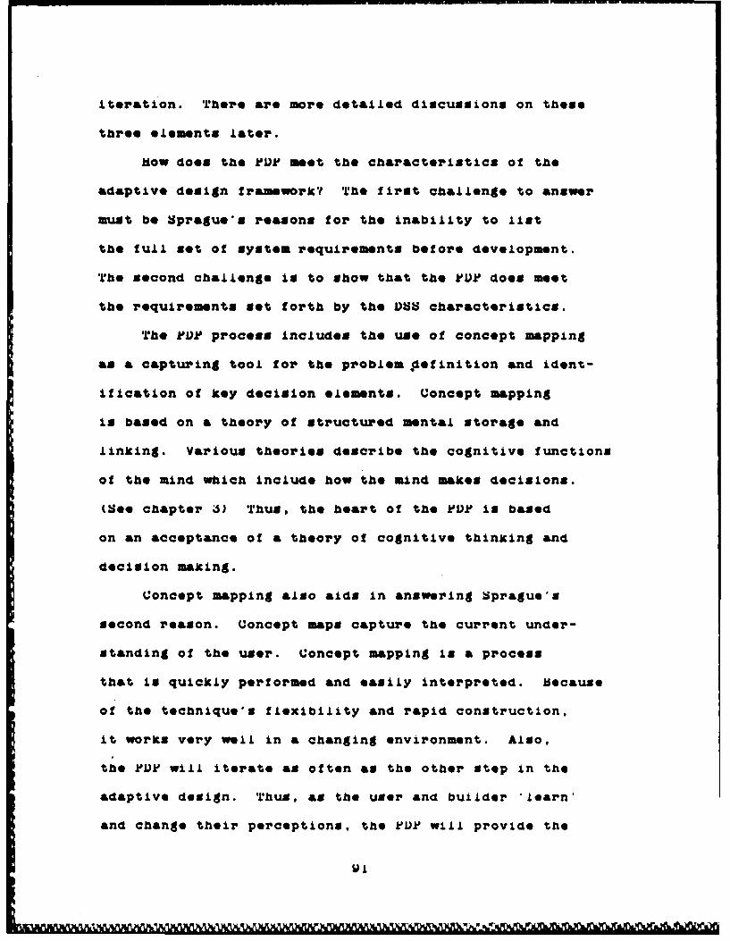
iteration. There are more detailed discussions on theme
three elements later.
How doom the k'IUk meet the characteristics of the
adaptive design framework? The first challenge to answer
must be Sprague's reasons for the Inability to list
the full set of system requirements before development.
The second challenge 1i to show that the ruD does meet
the requirements met forth by the UbS characteristics.
The POP process includes the use of concept mapping
am & capturing tool for the problem definition and ident-
ification of key decision elements. Concept mapping
is based on a theory of structured mental storage and
linking. Various theories describe the cognitive functions
of the mind which include how the mind makes decisions.
(See chapter 3) Thus, the heart of the PUPk is based
on an acceptance of a theory of cognitive thinxing and
decision making.
Concept mapping also &ids in answering Sprague's
second reason. Concept maps capture the current under-
standing of the user. Concept mapping is a process
that is quickly performed and easily Interpreted. oecause
of the technique's flexibility and rapid construction,
it works very well in a changing environment. Also,
the PUP will iterate as often as the other step in the
adaptive design. Thus, &a the user and builder "learn'
and change their perceptions, the VD? will provide the
W1
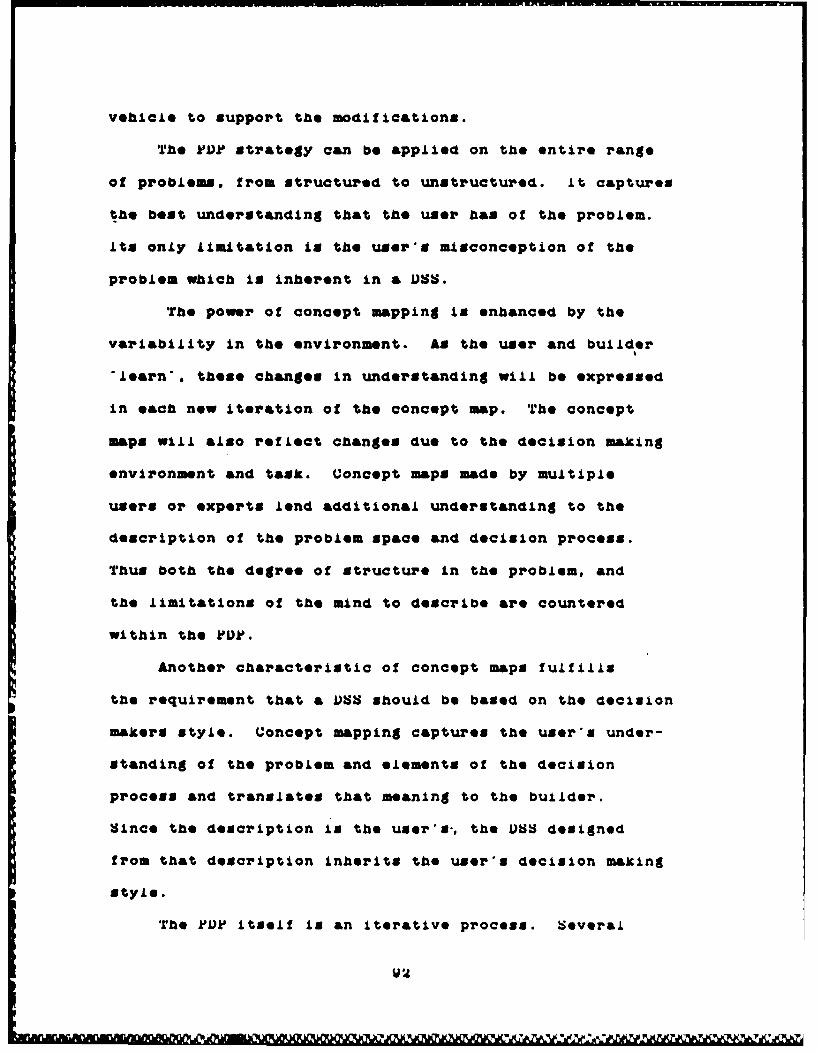
vehicle to support the modifications.
The POP strategy can be applied on the entire range
of problems, from structured to unstructured. It captures
the beot understanding that the user has of the problem.
Its only limitation is the user's misconception of the
problem which is inherent in a DNS.
The power of concept mapping is enhanced by the
variability In the environment. As the user and builder
"learn'. these changes In understanding will be expressed
in each new iteration of the concept map. The concept
maps will also reflect changes due to the decision making
environment and task. Concept maps made by multiple
users or experts lend additional understanding to the
description of the problem space and decision process.
Thus both the degree of structure in the problem, and
the limitations of the mind to describe are countered
within the POP.
Another characteristic of concept maps fulfills
the requirement that a DSS should be based on the decision
makers style. Concept mapping captures the user's under-
standing of the problem and elements of the decision
process and translates that meaning to the builder.
Since the description is the user•s-, the DSS designed
from that description inherits the user's decision making
style.
The ODP itself Is an iterative process. Several
W2

of the Stops repeat and iterate while producing just
one iteration of the design. As the design requirements
change, the various steps in the rDP act to incorporate
the modifications. Each of the steps are relatively
simple, easy to do, and can be readily manipulated.
This feature of the process fits in well with the iterative
nature of the adaptive design, and the reduction in
turn around time for each iteration.
There is one last feature of the ?VJ? that is not
a requirement of the adaptive design, but iS extremely
important to any system design. X&ch of the three elements
of the PDU provides a historical record of the DS &a
it is developed. This record can be used in a variety
of ways. A ULS design manager could use the information
as & cost justification record. Meador claims that
managers need cost benefit figures. 'Before approving
large scale DSS projects most managers need evidence
of some concrete benefits to offset development costs-
(Meador, IW4:L27). by having records of smaller projects,
realistic cost comparisons can be made. Another use
for the records would be in designing other DVSS from
the same problem domain. Information about a OSS built
for scheduling aircraft maintenance may be useful to
the designer of a )SS that schedules air crew training.
These records would give the user and builder a head
start on understanding the problem space and elements
II3%

of the decision process.
5.20 rhe P'rocess:
The process that is being proposed is nothing moroe
than a method of requirements determination. Yadav's
paper surveys the arena of requirements determination.
One of his findings is that a user "needs a methodology
to carry out the process of information requirements
determination systematically' (Yadav, laa5:b). Yadav
goes on to show that -the methodology provides a procedure
to understand an organization in order to reduce a possible
incongruence between actual and perceived requirements.
It also provides a tool to help describe organizational
functions in the form of a conceptual model- (Yadav,
I5.3:U). Figure b-I shows a diagram of Yadav's method
of determining the requirements for an information system.
Drawing from the methodologies suggested by researchers
like Yadav, Hira, Davis and the experience gained by
helping other students in designing their DNS proJects,
the PVP was developed. The VDL is a tool for developing
the actual design specifications of the prototype USS
and then aiding its expansion into the full system.
The YDP also doubled as a monitoring device to keep
track of the researcher's progress and as a guide for
the next set of actions.
P ~. d'.: -W4
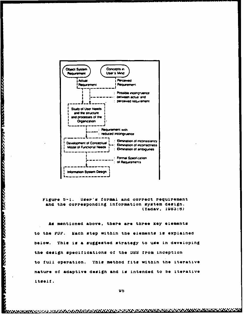
SACtual ecid
I t I ReqMnt
I I : .- le n~,.JnI I
between cua' andpercened reQ..ement
Stady of User NeeSI IaNo ft structure
amO process"s Of ft
Orgarzation 1I- .... 1"....I
I :Retuprent wo
"r -o Etoncmrc tual I•mknation of riconststencyit--. Ehmrmatson of ,conectness
Model ol Functoial Needs IL.....ij : aonolo ambogumes
-. Formw Spcf,,ationr of Requireme:s
------------
igur*e b-i. User's formal and correct requirementand the corresponding information system design.
(Yad&v, LUW5:O)
As mentioned above, there are three Key elements
to the kPk'. Each Stop within the elementS Is explained
below. This is a SUggested Xtrategy to use in devel~oping
the design specifications of the OSS from incieption
to full operation. This method fits within the iterative
nature of adaptive design and is intended to be iterative
itself.
LV

Davis surveyed the current field of initial requirements
determination and identified four strategies. Theme
strategies are: 1) asking, 2) deriving from existing
Information system, S) synthesis from characteristics
of the utilizing system, and 4) discovering from experimenta-
tion with an evolving information system (Davis, LW82:12).
The POD strategy, as described below, actually
incorporates the majority of these strategies. First,
the POP uses concept mapping in the direct asking type
of strategy. As Davis points out, asking yields satisfactory
reSults especially in the higher structured problems.
Deriving from existing systems can be easily done
with the built-in record keeping function of the concept
maps, feature charts, storyboards, and evaluation criteria.
As mentioned above, this information will aid future
DVS designers working on similar problems, as well as
being a teaching aid for new designers.
Adaptive design itself exploits the third and fourth
strategies of requirement determination. by rapidly
building and modifying the system and using ready built
hardware and software, the user and builder create the
system requirements with each iteration. Thus, they
use the knowledge -built into the current technology
and the "learning through experimentation to delineate
the final DSS requdiements.
The following discussion explains the steps of
Lth*.1fin,*i
fD S-i. equiemet
a
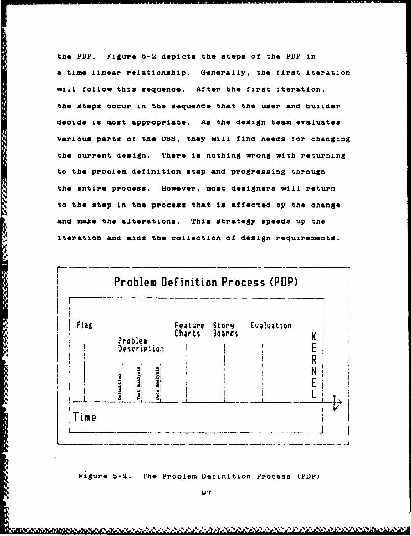
the FDk. iigure 5-2 depicts the steps of the ?VF in
& time linear relationship. Uenerally, the first iteration
will follow this sequence. After the first iteration,
the steps occur in the sequence that the user and builder
decide is most appropriate. As the design team evaluates
various parts of the USS, they will find needs for changing
the current design. There is nothing wrong with returning
to the problem definition step and progressing through
the entire process. However, most designers will return
to the step in the process that is affected by the change
and make the alterations. This strategy speeds up the
Iteration and aids the collection of design requirements.
Problem Definition Process (POP)
Flat Feature Star Evaluation
Flag Charts Boards KDescription
I •I I "r
Oi 1
Time i
ligSure •-2. rrie .kroblem IDeginition k'rocess (k'Vk)
U 7

b.21 The F'lag:
The flag is an indicator. It alerts the decision
maker to the existence of a problem. Some control mechanism.
or gut feeling will raise a signal flag informing the
manager that a problem or opportunity exists. The manager
may recognize that the problem is suitable for a VS.
Only then can he take action to begin the design and
development of a decision support system.
b.22 Problem Description - The Role of Concept Mapping:
The first stage in designing a I)S is to identify
the key decision(s). Keen talks about laying out the
key decision(s) within the framework of the problem
space. -This helps identify which decisions are of
most importance for effective performance and, of course,
which may benefit from decision support. If one then
assesses the quality of informational and analytical
aids for each key decision, one can begin to get a sense
of potential priorities for more detailed analysis-
(Keen, L*78: 173).
To identify the key decision, Keen suggests a cycle
of steps for the predesign phase (See Figure -ýS).
In this cycle, Keen's emphasis is on the first step.
The step calls for a descriptive study of the problem.
"The major aim of this predesign cycle is to make sure
that the right problem is worked on. There are , of
V -~.- * 'p )*.,*I. 8

course, many Interactions within the cycle; objectives
influence what the key decision will be and the areas
to be supported partly define available resources and
vice versa- (Keen, 1U78:173). His recommendation to
designer's of & USS is to complete two full Iterations
of the predexign cycle before beginning the detailed,
nore formal definition of system requirements and specific-
ations. Hiowever, with tools Ilike concept mapping and
the overall strategies built Into the POPF, two cycles
are not necessary unless it's the choice of the team.
N - Ob~M EOWY
isigure D h eeeig yle (eeI7tI4
06 0:110"fo
'V~~~ I~ m ~ '

Keen's cycle demonstrates the importance of the
problem description phase. Keen believes that by attaining
the best description possible, the user and builder
can define the key decision and elements that maxe up
that decision. The description phase is exactly where
the concept mapping supports the development of the
DU. In the POD the descriptive phase has three steps.
These three steps are the problem definition, task analysis,
and the data analysis. Concept mapping provides a vehicle
or tool for the design team to fully describe the problem.
5.221 Problem Definition:
The first use for concept mapping ,is to define
the problem space. The user constructs a concept map
based on his understanding of the problem. He attempts
to define what the problem is by showing the key concepts
involved In the problem and how they link together.
This map is then used by both the user and builder to
negotiate the meaning in the map. This negotiation
actually is an Iteration of the definition because
the user must fully explain or restate confusing portions
of the map so the builder "learns" and understands.
The map becomes a graphical representation of the
problem space. Since the concept map is the road map
that the design team is following, put it on large sheets
of paper and hang them on the walls for all to see.
Lou
by always keeping the map up in front of the design
team, changes in decision environment, decision task,
or perceptions can be quickly located and recorded.
Maps from several users or multiple maps from the same
uer, created over time, can be compared and evaluated
for the combined understanding and identification of
key concepts and misconceptions.
The map also depicts the limits of the problem
space. The links and concepts show the boundary of
the problem and may even express it explicitly. Thus
the map allows the design team to understand the problem
and identify the bounds on the problem am perceived
by the user.
5.222 Task Analysis:
The second phase of the problem description uses
concept mapping to identify the key decision elements.
Traditional computer design would call this phase the
task analysis. A task analysis is the listing and
sequential ordering of the individual tasks necessary
to solve a problem. There are a variety of methods
designed to accomplish this task, such as flow charts
and pert charts. Task analysis, used in this sense,
operates on very highly structured probleim. The task
to be captured by concept mapping is the individual
processes that are used in the solution to a semi- or
10l

un-structured problem. In this sense, the ordering
of the task Is not necessarily linear or sequentially
well defined.
There are other methods that are being developed
to identify key elements in the decision process. One
of those methods is C-MAY. U-MAk as proposed by Hir&
and Mori attempts to determine the. need statements of
& problem. In their problem analysis phase is & task
called 'structuring the problem'. 'in this process,
complex factors are arranged in order and critical points
for problem solution are found' (Hir&, Ai82:iid). The
process seems to be a mix of traditional task analysis
and cognitive task identification,. The big drawback
of this process is the reliance on a structured problem
or process.
iDuring the task analysis phase, the user constructs
another set of concept maps concentrating on his/her
perception of the decision process. The purpose of
these maps is to identify the cognitive task necessary
for Solving the problem. The user describes the process
s/he would use to solve the problem. In reality, the
user activates his K-lines, or the ones he thinks are
most appropriate, and records the results. The map
captures the events or cognitive tasks in a graph.
The order and specific sequence is not represented except
in very structured problems or In the structured parts
!O~
of unstructured problems. but, the elements of the
decision making process are captured. This map can
then be presented to the rest of the design team for
another negotiation of meaning.
Once the decision process map is constructed, an
evaluation of the key decision elements is undertaken.
This is not & formal evaluation, but an informal search
for the kernels from which & DVS could be built.. The
design team lists all of the possible kernels and their
role In the overall decision proceas that were found
in the process map. Chapters 0 and 7 will demonstrate
the problem description process and show the many kernels
identified from a variety of problems.
5.223 Data Analysis:
The third and final phase of the problem description
comes directly from traditional computer system design.
Once the process maps are constructoed, they can be used
to establish the input and output specification of the
system.
Uoncept maps from the task analysis provide the
graphical representation of the processing taking place
in the system. by adding the input and output parameters
to the events represented on the process map, the design
team has a pictorial representation of the data require-
men ts.

The data analysis is a rather simple process because
it works with very highly structured parts of the problem.
The design team takes the task analysis maps and identifies
the type, format, and form of information required and
lists it on the concept map. This identification is
accomplished for each event or process taking place
in a decision element. The same procedure is followed
for the output as well. After all the input and output
identifications are made, & complete met of data requirements
are compiled and form the beginnings of the system require-
ments. In actuality the user did not construct any
new maps, but modified the task analysis map to reflect
the data requirements.
The three elements of the problem description work
together to present a complete picture of the problem
space. it may have taken several iterations among the
three sets of concept maps, but the best understanding
of the problem space is understood by the design team
and Is represented in an easy to review and modify format.
Once this information has been collected, the initial
design of the DSS is ready to begin. For each of the
identified kernels the team needs to create a set of
feature charts and storyboards depicting a pictorial
representation of the DVS and its functions.
104
l C. F

b.23 Feature Charts and Storybo&rds:
In the phase of the problem definition process,
the design team takes what they have discovered from
describing the problem and starts to form It into &
description of the OSS. The two processes, feature
charts and storybo&rds, are off-shoots of the RUMC approach
of Sprague and Carison. The following discussion takes
& brief look at the these three topics and their role
in the pup)k.
Spr&,aue and Carlson made five observations about
decision makers. -First, decision makers have trouble
describing a decision making process, but they do seem
to rely on conceptualizations, such as pictures or charts,
when making or explaining a decision. Second, Simon's
int*ellience-design-choice scheme can be useful in categor-
izing decision maker's activities, even though the decision
making process may be difficult to explain. Third,
decision makers need memory &ids. Fourth, decision
makers have different styles, skills, and knowledge.
Finally, decision maker's expect to exercise direct personal
control over their support' (Sprague, LW82:U8-W).
These observations led them to propose the AUMC appro&ch
to OSS design.
The WMUA approach is a process independent approach
to defining the requirtements and specifications of a
1)55. Their original recommendation was to use flow
Lob
charts, input-output models and other pictorial devices
to represent the different parts of the DUS. The four
components of the HUMU approach are kt-kLepresentations,
O-Operations, M-Memory &aids, and C-Uontrol mechanisms.
Teo DSS is divided up by the four components and described
with respect to each of them. This makes the HOMU approach
"" a framework for identifying the required characteristics
and capabilities of a specific DS" (Sprague. AU62:1A0).
As a framework for design, RUOW works very well.
SMUlW's guidance provides the design team with the basic
tools to describe and depict the USS. However. feature
charts and storyboards, which where derived within the
NUOW framwork, provide much clearer and more flexible
description tools. These tools enable the user to -seet
the design of tae USS as it is developed.
Feature charts provide the process aspect of the
USS. 'The feature chart snows the features of the system
with which the user interacts. These features are the
representations, operations, and control mechanisms,
as weil as the supporting memory aids- (Seagee, AIWO:lA).
Figure U-4 shows a feature chart from a DSS design
as a class project. Each symbol represents a specific
component of the )SS. Solid lines depict control transfer;
parallelograms depict menus; curved rectangles are
files; and plain rect&angles show operations.
100
N. N 'W~~~~a '

-C A 'r ,
ILi
Yigur. 5-4. Feature Chart
The feature Chart Shows both the user and the builder
the perceptions of the USS and the user's needs. This
chart shown the data flow, points of control, and proposed
paths of sequentially ordering the processes. Thus,
the feature chart Is & pictorial for the design team
iul
tIt t n IXN design
'ine'he fe aturee chart l ays, bout the orgx`aniza hetionJ.e
ofnc the sysemthxe storboar detailst each ompoi~e•net
of the sytem, ~e St ox`•o~xI 07,lsechcmoet

Andriole off*eS a tool to the design team that exploits
both the NOW. approach and the human's desire to describe
things with pictures. One way to explain a storyboard
is to look at a comic strip. kach frame in a comic
strip shows a different picture that supports the story
line. The DU storyboard does the same thing. Each
frame is the proposed monitor screen that the user would
See when the DSS is up and running. Comparing it to
the feature chart, each component on the feature chart
would have its own frame in the storybo&rd. Thus, the
user and the builder would see and agree on the user
interface.
This storyboard carries a lot of information.
The user designs thte frame by putting in the necessary
information, suggested output format, and desired controls
for the operation. It also lets the user have a forum
in which to describe the underlying operation that would
take place. The builder gleans the requirements from
the frame dealing with the data file and processing
interactions, and input/output formatting. The builder
can also use the frame as a forum to describe alternative
formats and controls. Storyboards, just like concept
maps and feature charts, are communication devices that
help the design team to determine requirements for semi-
and un-structured problems.
lob
-Y • r v -•;. ;•••J ¢•••,•••.• •• • , -•' ', . .'• .v ,•.,- o v.'
b.24 Xvaluation:
The final phase of the problem definition process
is the weakest. Very little has been written on the
subject of OSS evaluation, but this is the key issue
in designing and successfully developing an effective
decision aid. Much more research and development on
the criteria for evaluating the mtorybo&rds, feature
charts, and concept maps needs to be done.
As of this writing, the best recommendation for
criteria lies in the common sense of the design team.
However, four &re&s may help to focus the evaluation
of the USS design. These four evaluation areas are
derived from Sprague and Carlson's four measures of
OSS evaluation. These four measures are: 1) Productivity,
2) Process, 3) Perception, and 4) Product (Sprague.
LU82: 00).
The design team should review the products of the
POP with regard to several points of view. First, the
user interface should have little if any distraction.
Is the USS,'as designed, easy for the user to learn
and use? How often does he need to use the help function'?
Second, has the decision environment, task, or user
perceptions changed? If something has changed, what
are the effects on the design? Third, look at the service
that the )SS is providing. Does the )SS support the
decision maker in the actual problem or Is it not &ccur&tely
i0w1
focused? Doom the USS support Other problems that Were
not initially stated in the design? if so, doom this
extra support distract the user from tat primary purpose
of the DSS7 F'inally, the design team needs to look
at the productivity of tat USS. H~ow well does the DSS
perform? La it Worth the Cost of development and continued
use?,
While little has been written on the subject, one
paper is noteworthy. Adelman, Htook and Lehner evaluated
five USAI' PSS prototypes that aid tactical decision
making. To complete this assignment, they developed
a questionnaire that looked at three separate interfaces.
The three interfaces are the OUS/user, the Umor-OSS/
Organization, and the Urganization/Environment. (Adelman.
Although the results of the evaluation are not
important to this paper, the fact that an evaluation
could be approached in this matter is. Theme are just
two examples of the many ways an evaluation could be
structured. and implemented.
b.2 Kernels:
This entire process of determining the specification
can be done In two ways. The choice Is based on the
design team and how they view the problem space and
its kernels. First, the POP~k can operate on one or more

kernels at a time. For very large problem spaces with
many kernels, this is the recommended approach. This
approach breaks up the design into smaller chunks or
pieces. The advantage in chunking the DSS design is
to allow the design team to develop kernels and groups
of kernels at different rates. The rate is based on
the user's understanding of that portion of the problem
and the capability of technology to support the development.
Thus the design team gains the ability to focus scarce
resources on feasible and more highly promising parts
of the DSS.
As the specifications of these pieces of the overall
VSS are collected, comparisons and evaluations among
the kernels and their roles in the DSS can take place.
These evaluations give upper management the information
they need to manage the development of the DSS.
The second strategy allows the VD? to establish
the design requirements on all the kernels identified.
This should be used when developing a simple OSS. This
approach makes all kernels of equal value and progresses
them at an equal pace in development.
5.JU Conclusion:
This chapter presented two key issues. The first
issue was the need for an adaptive design for DV develop-
ment. A DVS was shown to be an aid for problems that
Ill

lacked structure and could not be defined by a complete
set of requirements prior to development. Therefore,
this type of system needed to be developed in an evolutionary
manner. The second issue proposed a method (k'D) and
the tools (concept mapping, storyboards, and feature
charts) to determine the requirements for a DVS. The
method divided into three maJor elements, each with
separate steps and tools. The V'V was proposed as an
iterative process that evaluates the design and records
the DSS modifications.
Chapter 0 records the results of experimenting
with concept mapping as a tool for acquiring the problem
definition and identifying the kernel. Later in chapter
0 are examples of concept mapping's integration into
the design phase of a DSS through the adaptive design
approach.
112
i

chapter 0
kxamples of Concept Mapping Applied to Problem Description
0.00 Introduction:
This chapter is a compilation of examples. Several
exercises in DSS design are listed as examples of actual
applications of the concept mapping technique. These
exercises explore a variety of problem domains.
A short discussion introduces each example and
then shows the results of the concept mapping exercise.
The concept maps that either define the problem space
or describe the decision process are shown in accompanying
figures. In some of bhe examples, a table lists the
kernels identified in the exercise. Two of the exercises
also include the entire DSS design showing examples
of concept mapping, feature charts and storyboards.
0.01 Source of Examples;
These problems came from three sources. The first
problem is a test case problem. It demonstrates to
analysts what a concept map looks like and how concept
mapping can identify the kernels in a USS design. The
rest of the examples are actual D1S projects derived
from either class assignments or thesis proposals.

0.2Crude Maps!?
The maps listed in the following exercise are,
in many cases, the map exactly as it was constructed
and finalized from the interview. Consequently, the
maps appear in a crude format. There are two reasons
the maps are left in this crude state. The first reason
is to show the new concept mapper that although neatness
is helpful, it is not absolutely necessary for the transfer
of understanding. The crudeness of the tool does not
detract from the communication ability.
The second reason for the crude state of these
maps is to show that maps need to be flexible and created
quickly so as not to stifle the creativity of the source.
During the interview the concept mapper needs to concentrate
on the source and capturing his/her concepts and links.
If the concept mapper worries about neatness, the constant
'fixing' of the map will distract the source and may
even lose the meaning.
There is plenty of time after the interview to
clean up maps. By using the audio tape recordings,
details can be added and hierarchial relationships checked.
Formal presentations and reports may require the analyst
to formalize the maps similar to the style shown in
the next chapter. For the adaptive design process,
the original maps in their original format, prominently
displayed, is enough to keep the problem focused for
1 14

the entire design team.
O.O Why the reader may not agree with the kernels:
The kernels identified are based on the perception
of the user who created the map and the reader who is
interpreting the map. With two different people reading
the same map, different kernels may be identified
because of their perceptions. This means the team of
DSS designers, users and builders, must agree by negotiating
the meaning represented in the concept map. Then the
team can list and evaluate all possible kernels to determine
the key kerneAls). This selection of key kernels sets
the DS-s style, design direction and the team's perception
of the problem solution process.
0.iO Xxample I - buying a Car:
When concept mapping was first considered as a
technique for problem definition and kernel identification,
it needed a test case, or test problem. The purpose
for this problem was to demonstrate to a OSS designer
the ability of the concept mapping technique. The problem
had to be a reasonably good forum for a VSS and yet
common enough for any designer to relate to easily.
The problem chosen was 'buying a car'. This problem
space had one big advantage. 'Buying a car* was a decision
most people have experienced. This meant decision makers
i Ib

already had many of the decision processes established
in their minds and could readily recall them. The concept
mapping technique was then introduced to the decision
maker without worrying about having to teach all the
details of the problem. Thus, it made & good example.
The observers were relatively familiar with the problem
domain and were able to concentrate on the concept mapping.
The 'buying & car' problem has been the main example
in every introductory presentation of concept mapping
to date.
With the problem domain chosen, a concept map was
created to show the tasks in the process this author
would use. The map is shown in figure 0-1. Based on
this map several kernels were identified. Some of them
are listed in table 8-1.
Possible Kernels for a DSS on 'Buying A Car'
- Working the BUDGET portion of the decision processa Cash flow sheets for monthly billsa T-accounts for savingsa Loan/Interest payment modelsa Leasing payment models
- Checking the Marketa Data base on maker's offers and inventory
- Buyer Wantsa Data base to list and rank user desires
- Other Optionsa Data base on each of the available alternativesa Cost modeling on each of the alternatives
Table 8-1. Possible Kernels
118
U- U- . w

?.t uz. ~ W L. On .p Map ki y ng a (a
4 1*4
V ~~~~T CA
.~~

a..~ ce
or..dbw
f -men am0. rift TWO*
4-111"ma LIN"
.m..m.%auWA11111116111m dift
Tloiiie plý left
ams-1111
P-0 sk-allolefew.m ow
Ilk-
JIM VON" cbmse-ft too"
Dommom
0-.Nwwm ft.
FiglAre 6-2a. Concept Map: "Compromised Information Problem, '3pacc,"
Liw

---- - p ------ - -- -
Ia
I.4
II -�
I�1I I j��i 1! Ii
I
* I
� '�1IAk ii
A aj
J
V

0.30 kxample 0 - Adams' Tanks:
Capt bill Adams' initial thesis proposal suggested
& OSS to assist the decision makers of the U.S.Army
in distributing tanks to various units. consequently,
he worked on developing the definition of the problem
using concept mapping. After several interviews and
a variety of concept maps, he determined that vDs was
not the beat way to approach this problem because the
structure of the decision.
The exercise with Capt Adams was not counted as
a failure. The concept maps created did show the problem
space. Also, the concentration required on his part
helped him to understand the problem more clearly.
Finally, valuable time was saved by not pursuing an
inappropriate solution method.
0.40 Uxample 4 - Pilot Training Scheduling:
Capt Paul Trapp and Capt Jeff Urechanik chose to
build a )SS that assisted a scheduler. The resources
that needed to be scheduled were pilot trainees and
instructors. both officers had held the position in
earlier assignments. Therefore, both were taken to
be the experts as well as the builders.
This example held two noteworthy events. First,
this example was the first to apply concept mapping
to the actual design of a VSS and also continue the
12"
-1 .¶.0*1E~*

process through to a fully operating prototype. Second,
it was the only example of a DSS design that used more
than one expert. Multiple experts would not be encountered
again until concept mapping was applied to the kapid
Application of Air Power problem space.
Several specific steps were taken to concept map
the problem and decision process. First, each expert
Independently prepared a list of what they thought were
the key concepts in the scheduling problem. Most of
the concepts were events, tasks that the scheduler needed
to do. From these lists the builders grouped and time
ordered the concepts. Table U-2& through 0-2c and figure
U-4& show the concepts chosen and reordered by the builders.
Only after each expert had thought through the
exercise of key decision processes and ordering did
they come together and build their first Joint concept
map. This first map accomplished two key goals. The
goals accomplished were: i) defined the problem space
to a mutual agreement and understanding of both experts
and 2) taught this author about the intricacies of sched-
uling. During the exercise, many discussions occurred
between the two builders concerning the other's choice,
placement and grouping of concepts. The resulting problem
definition map is shown in figure U-4b/c.
Several interviews were held. They resulted in
a series of maps that attempted to capture the process

& scheduler went through in his daily selection and
Key Items to Perform Daily
Check yesterday's schedule to make sure all flightswent as scheduled.- Mot*e deviations"- find reason (weather, sicketc).- Update boards.
(ather all inputs for tomorrow's schedule- Who's available?- DONL.- TDO.- Leave.- Academics.- Appointments.
Determine all fiying/training/ground events to befilled.- F'lights.- Simulators.- Academic Classes.
F Aill lines.- Make sure formations match missions.- Students first.- Shuffle Instructors so that they're assigned correctly.
0Fil academics first.
F 'ill duties second (important duties).
- Ramp officer.- Appointments.- SU F.
Fill piddly stuff last.- CO.- Appointments.- Meetings.
0 Deconflict throughout schedule.
'rable u-2a. Orechanik's List of key concepts.

Key Items to Yerform Daily
* Fill in grease board with times, simulators, academics,meetings, which ride student's on.
" Deconflict academic ciasswise
" Fiil in instructor absences, DRIF, meetings, on thedeconfliction board.
* Fill in set rides such as check rides, DO flyingwith squadron.
*Look at graduation dates or class or individual furthestbehind (red dots only fly once).
* Fill in student names and which ride they are on.
* Look for type rides (air-to-air) or (air-to-ground).
* kut in student names with a match from the ride theyare on compared to the configuration of the planes ata specific take-off time.
* Fill in exclusive periods for each class first usingprevious step .
* Match 1k' to student names according to squadron rules.For example, the 44th has a primary and secondary 1Y
assigned to the student. if neither the primary orsecondary 1k is available then match the student witha 1k from his flight. If none of his flight is available,then any III will do.
iterate all steps.
Table U-2b. Trapp's list of key concepts.
124
J - I~

Odred Key Concepts
1) Ensure data from today's Schedule iS updated onceflying is complete for today's schedule.
(night before or first thing in the morning)
2) Write up the shell on tomorrows portable grease
board.
3) Write in hardlines.
4) Write in DN1Fs, leaves, CUC, SOF (duty hog).
5) Talk to Sig 3 (Sq CC, Ups Off, Ant Ups Off).
0) Write in academic schedule classes and instructors(weekly).
7) Matching process:a) students < --- > instructors
1) Look for assigned Instructor2) Look for I? in Flight3) Look for anyone
8) Schedule'Big a.
.) Schedule simulators.
10) Schedule duty bog.
Ii) Vill in deconfliction board.
12) Write daily grease board up on large board -
Table 6-2c. Trapp's first ordering of key concepts.
a~

-- A
FILLdELE
Ptl r- 4q- A4 'A.*M
Me IL
Yigure U-3Sa. (irechanik's ordering of key concepts.
'12b

ii d f4
16.5.
AMC~
Figure 6-3b. Concept Map: F.irst cut at k'robLem Space.
?± -
! % % % % , U

•f.Vd4 Ar
/r
VV
.1i Jl
Figure (J-Sc. Concept Map: F'irst Cut at Decisi~on P'rocess.
-12
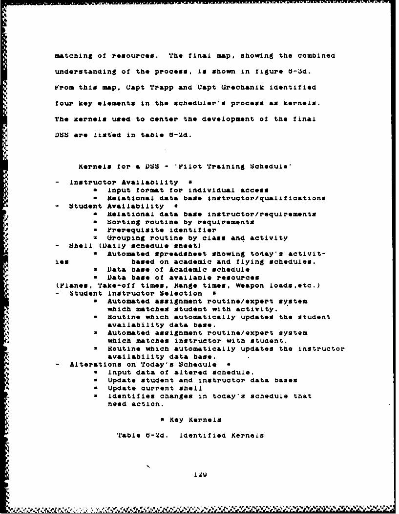
matching of resources. The final map, showing the combined
understanding of the process, is shown in figure O-6d.
From this map, Capt Trapp and Capt Urechanik identified
four key elements in the scheduler's process as kernels.
The kernels used to center the development of the final
DSS are listed in table O-2d.
Kernels for & V) - 'Pilot Training Schedule'
- Instructor Availability *a Input format for individual accessa Relational data base instructor/qu&aifications
- Student Availability *a Helational data base instructor/requirementsa Sorting routine by requirements
P rerequisite identifiera (rouping routine by class and activity
- Shell (Daily schedule sheet)a Automated spreadsheet showing today's activit-
ies based on academic and flying schedules.a Data base of Academic Schedulea Data base of available resources
(Planes, Take-off times, Range times, Weapon loads,etc.)- Student instructor Selection
a Automated assignment routine/expert systemwhich matches student with activity.
a Routine which automatically updates the Studentavailability data base.
• Automated assignment routine/expert systemwhich matches instructor with student.
a Routine which automatically updates the instructoravailability data base.
- Alterations on Today's Schedulea input data of altered schedule.= Update student and instructor data bases* Update current shell
I Identifies changes in today's schedule thatneed action.
SKey Kernels
Table U-2d. identified Kernels
12W

W ~ t w ~ ww ~ w wp p .so
ftL
IQC. 1447~L1
Ail qs-"a~-' ?7
A.im
-~~ ----------------
ra~Asi S"uo0. S6 Lifes
i~igur. -~3d. ?ia.L Concpt Map o Q)I).iuo 'ce.
Lf!a%3O~d ia"Z
~rL

O.bO Example b - AWACS Manpower Manager:
Maj bill Schneider's thesis effort looked at the
management of manpower resources in the various positions
required by the AWA•US system. He built a VSS that assistel
decision makers in maintaining manpower, training qualificat-
ions and experience levels.
Maj Schneider used concept mapping to scope the
problem and define the problem space. His resulting
concept map of the problem is shown in figure U-4.
. iFrom this understanding of the problem space, he went
on to full production of a prototype 1)SS. His prototype
demonstrated that the goals of manpower management.
outlined in this concept map, could be supported and
maintained.
p ''• • a/T•,• T
• •.'tigure U-4. C~oncept, Map: "AWAC;S Manpower" Managament,
S.
U.S~11 fix% ~ % % \
t.tso xxample u - Tactical Nukes:
For TACT 7.01, Command and Control, Capt Bob bivins
and I established the system requirement for a prototype
1U). The only requirement from the course was to recommend
the design of a 1)5 that would assist military decision
makers with a command and control issue. Therefore
we decided to obtain the system requirements using the
VFD approach as described in chapter 5.
The problem chosen was an intriguing look at the
question; 'When should a theater level commander request
authorization for the use of tactical nuclear weapons.?'.
Since no expert was available, we conducted an extensive
literature search of the problem and related issues.
This search plus our ten years experience in strategic
nuclear missile systems, established ourselves as the
best experts available.
The literature search revealed the existence of
plans requiring the NATO theater commander to ask for
the authority to arm the weapons from the Yresident.
The commander was required to justify the arming as
a necessary and politically feasible action at that
time in the conflict. In other words, the plans expected
the action to achieve battlefield objectives without
having to release the power. None of the tactical employment
issues nor specific conditions of release were addressed
in this )SS. Only the collection of information and

evaluation of the situation which would assist the commander
in making and justifying the request.
Appendix C holds the final report from the project.
All of the concept maps, feature charts and storyboards
are included. This was the second example of using
the Macintosh computer system with Mac Draw.
6.70 Conclusion:
This chapter was designed to encourage other analysgts
to use concept mapping and the problem definition process
in their next DSS development. The chapter has shown
a variety of decision support systems and problem spaces
"where concept mapping and the entire problem definition
process was applied. In every example the problem space
was more clearly defined by using the concept mapping
technique. This enhanced understanding of the problem
space aided the designers in their search for the system
requirements and development of a OSS prototype. These
exercises have given )SS designers a variety of examples
for the specific use of concept mapping in problem definition
and kernel identification.
4?4?
-j

Chapter 7
Application of Concept Mapping - RAAP
7.00 Introduction:
This chapter records the experimentation done by
applying concept mapping to a very large problem domain.
Recalling from chapter 3, concept mapping can be used
at any conceptualization level. Thus, a large, undefined
or fairly new problem domain allows the demonstration
of concept mapping at a higher level of conceptualization.
The following discussions look at the progression
of the experiment as well as the findings and observations.
The first discussion explains why the RAAP problem domain
was chosen as a test bed for concept mapping. This
discussion lists the several advantages which make RAAP
ideal for the experiment. The second discussion looks
at the facts of the experiment. Included in this section
are a background on the RAAP concept, the set-up of
the experiment, and the procedures of interviewing.
The final discussion reports the findings and observations
by dividing them into three categories: 1) results
from individual mappings, 2) aggregation of group data
into two maps, and 3) the general observations of the
experimental procedure.
This chapter has two goals. The first and most
134

obvious goal is to show the power of concept mapping
on a rather large and nebulous problem area. Quite
a bit of detail is reported in the following discussions
on the procedure and results of concept mapping in this
domain. Under both the individual and the aggregated
discussions are general comments about the maps and
how they were created. The second goal is to relay
the understanding of the RAAP concept to the reader.
For this reason, large amounts of time and effort were
taken to redraw all of the maps. This ensures the reader
has the most effective map available from which they
can learn. Normally the map would not be formalized
because concept mapping is a working tool for problem
definition and kernel identification.
7.10 The Advantages of the RAP Problem Domain:
RAP was suggested during the preliminary thesis
proposal discussions as a problem that would be more
complex than the DSS projects. The problem space did
reside iii a much higher conceptual level. This means
that the problem space crossed several knowledge domains
and utilized a variety of cognitive and decision processes.
From limited information on the concept, RAAP seemed
to be an interesting yet advantageous problem domain.
RAAP has sever&l advantages for its choice as the problem
domain: 1) convenience, 2) size of the problem domain,
135

3) lack of universal understanding of the RAAP concept.
and 4) the need for support of research and development
goals.
The first advantage of RAAP was its convenience.
AFIT had already made arrangements for Col Rothrock
to make a presentation on the concept of RAAP. This
allowed immediate access to the prime expert in the
field.
The second advantage is the shear size of the problem
domain. RAP covers several knowledge domains and calls
for many types of human decision processes to be captured.
For example, the fusion of detailed battlefield data
into a complete picture of enemy actions requires collection,
counting, Judgement of accuracy, collation of different
sources, tracking, and unit identification am a few
of the elements of the decision process. This is just
one of the many decision processes involved in the RAAP
concept.
The third advantage was the lack of general under-
standing about RkAP throughout the military establishment.
Col Rothrock and Col Kline have spent several hundred
manhours briefing the concept of RAAP. Many levels
of the military and government establishments have been
exposed to the "new way of thinking'. However, literature
searches failed to retrieve anything significant that
described or explained the RAAP concept. This indicated
138
b

AI niL MR v Wiifi Ar. MR
the newness of the concept and the lack of other authors
or agencies to think about enacting or implementing
it. Thus, it was concluded that few people outside
of the Air Staff, a few contractors and Rome Air Develop-
ment Center (RADC) understood the concept. This lack
of universal understanding made RAAP an ideal problem
domain. *Experts* were much easier to identify because
there were so few.
The fourth advantage is that research supporting
RAAP is Just beginning. The engineers at RADC are looking
for additional support in identifying the directions
of research and development efforts. (Papagni, 1987)
Since they are tasked with managing the research for
the RAAP support systems and building the demonstration
prototypes, they would like to know several things.
1) What part of the system gets built first?
2) Why is one element more important than another?
3) Why do we need this piece of the puzzle at all?
The Air Staff is also interested in the research goals
and the direction that RADC is taking. By knowing what
¶ they need in the way of developments, they can assist
in the management of research and gaining financial
and political support.
In the previous chapter, there were examples where
concept mapping identified kernel(s) for DSS projects.
By extending that process to the larger domain where
137

several decision processes take place, the kernels identified
will be the key decision processes and major elements
of a decision process. This identification process
will produce a list of kernels for researchers to consider
as goals. Thus, an evaluation system could rank the
kernels in order of importance. A similar procedure
would be beneficial in the acquisition phase of a system
as a statement of initial requirements. If concept mapping
at this level can identify the kernels, then evaluation
of the kernel can take place and a ranked listing of
the kernels produced. This final product becomes the
basis for the advocate's request for funding and political
support (i.e. a planning tool).
Besides all the r4vantages favoring RAAP as the
test bed problem for the concept mapping technique is
the fact that RAAP addresses itself to the field of
command and control. There is a great need for understanding
the decision processes in command and control. "Very
little time or effort has been spent uncovering the
processes by which command decisions are made; even
less has been spent describing the cognitive operations
which decision makers perform when confronted with compli-
cated and often urgent C2 problems.' (Andriole, 1982)
By using the concept mapping technique of RAAP some
insight into the command and control decision process
might take place.
138U.

If this insight does take place, then the research
effort expended on the development of RAA can take
the 'decision maker approach'. Concept mapping would
give the researcher the view of the decision process
directly from the user or commander's view. Thus, the
development would be built around user needs, not machine
capabilities. What is meant by the 'decision maker
approach' is that the command and control systems would
be designed as supporting elements for the decision
processes that need to take place. Andriole calls for
this approach as if it were a necessity. "C2 systems
ought to be designed from the decision makers up, not
from the electronics capabilities down.' (Andriole,1982)
Based on these advantages and needs, RAAP was chosen
to be the problem domain for this test of concept mapping.
One question remained. It dealt with the procedure.
Was the approach that was used in the DSS examples adequate
for this level of conceptualization or were changes
required? Assuming the basic procedure outlined in
chapter one would result in the same or better success,
no changes were made. The next discussion records the
experimental procedure and the adjustments made.
7.20 The Experiment:
This is not an experiment in the true scientific
sense of *a sequence of observations carried out under
139
V :- 'N %W f'. % % % %•*
controlled conditions" (Metcalfe. 1988). The experiment
is a trial. Using the concept mapping technique, an
attempt is made to achieve two goals. The first goal
is to identify key elements, kernels, in the decision
proceses. of RAAP. The second goal is to build a map
that aids in transferring understanding between individuals.
The trial is not in a controlled environment. The expected
result is an increased understanding in the problem
and its decision process elements. Following is the
hypothesis for this experiment:
'Concept mapping conveys understanding of complex
concepts, like RAAP, between individuals and aids
in the identification of kernels.'
The measure of effectiveness or measure of degree of
accomplishment is the response from the experts and
their eventual use of the concept mapping products.
In other words, the best measure of the success of the
experiment is the value the experts place in the maps
and the list(s) of kernels.
The main goal of this trial session is to see if
concept mapping can identify key elements or kernels
in the RAAP process. Before delving too deeply into
the procedures, there is a need for a short discussion
of command and control decision making and how RAAP
fits into the concept of operations employing air power.
140

7.30 RAAP - Background:
"Theore is no adequate foundation for a theory of
command and control and, hence, no guiding principles
for system design and evaluation (Wohl, 1981:818).
This was the maJor finding of a Secretary of Defense
colloquium in 1979 on command and control. Unfortunately
little has been done to improve this situation since
the Secretary's colloquium.
For too long command and control has been an art
form for only a few select commanders. The effort to
educate and train young officers as skilled tacticians
in applying air power is very weak. Even commanders
in Europe at the highest level of responsibility for
directing battle are not necessarily prepared for the
demands that command and control require (Suter, 1987).
Consequently, the emphasis in eitablishing command and
control procedures and ensuring that those procedures
take full advantage of the modern weapon system's cap-
abilities is, to say the least, lacking.
"Western technology boasts a family of new weapons
and reconnaissance/surveillance systems with unprecedented
capabilities. Yet command and control of these forces
has not kept pace. Today an operations decision maker
would be potentially deluged with target information
that can describe and display floods of eligible targets
yet lacks an equivalent complement of explanatory information
141
to permit weighing and prioritising those targets relative
to the combat situation confronting him. Without better
development and analysis of attack options, the potency
of the air arm is condemned to a reactive, target servicing
posture that makes regaining the initiative under the
amalgam of combat pressures virtually impossible" (Rothrock
and Kline, 1987:5).
What is needed then is a theoretical basis for
command and control and the procedures to enact the
theory. Wohl insists that *...a theory of command and
control must start with a theory of decisionmaking for
command and control.' (Wohl, 1981:618) In response to
this need of a command and control basis, came the concept
of RAAP.
RAAP is a new way of dealing with the information
flow on a battlefield and the support given to the com-
mander. RAAP offers a theoretical base from which procedures
for commanding and controlling forces are derived.
It is a new way of thinking about the air operations
and application of air power. The RAAP concept redefines
the function of command and control. It harnesses the
power available in information through advanced machine
capabilities. *The procedures are designed around the
needs of the commander and his decision processes by
managing and displaying information. The result allows
the commander to take advantage of preplanned actions
142
and exploit the enemy weaknesses.
This approach to command and control fits very
well with the conclusion that MaJ Orr finds in his research
of Command, Control, Communications, and Intelligence
(CI) and combat operations. Here Maj Orr offers a
definition of command that parallels very well with
the RAAP concept of command and control. *The stochastic
nature of combat and the varying degree of actual command
decision impact on the combat process suggest that the
primary function of command in combat is managing sources
of potential power in order to be able to exploit
opportunities as they &rise* (Orr, 1983:47).
RUP finds further support from MaJ Orr's definition
of control. He calls for the need of forces to exploit
the enemy's weaknesses. 'A primary function of command
is deploying and maneuvering forces or other sources
of potential power to be in the best possible position
to exploit opportunities as they arise. This function
can be viewed as controlling the power distribution'
(Orr, 1983:51).
RAAP is the vehicle in which these definitions
of command and control are realized. By implementing
the RAAP concept, commanders expect to harness the true
power of the weapons systems under their command, by
using them more effectively (Rothrock and Kline, 1987).
143

7.40 Experimental Procedure:
The first task was to gain a basic understanding
of the concept RAAP. The lack of literature made this
a more difficult task than the DSS proJects worked on
earlier. However, a point paper, written by Col Rothrock.
and listening to the first lecture presentation provided
the initial knowledge base to support the interviews.
Two appointments for interviews were set with Col
Rothrock during his visit to AFIT. The first interview
consisted of a short presentation about concept mapping
and its proposed value to problem definition. The main
goal of the concept mapping exercise was stated as that
of identifying kernels. At that time little was known
of the extent of the research and development for RAAP
nor of any of the researcher's needs. Col Rothrock
participated in the remainder of the session as the
expert. He concentrated on his understanding of RAAP
from a doctrinal view. Much of his understanding came
from an information processing point of view. At this
point in the development of the technique, it was assumed
to be a worthwhile way to approach the problem. This
approach changed later in the development and will be
d reflected in later maps.
After both interviews and attending both of Col
Rothrock's presentations, several maps were created.
See figures 7-2a through 7-2o. Col Rothrock reviewed
144
a few of the maps from the interviews and agreed that
they did reflect his understanding of RAAP.
Col Rothrock felt strongly that concept mapping
had significant value. He provided the funds which
enabled a complete set of concept maps to be generated
from all the key experts in the field. This generosity
provided the opportunity for a more explicit definition
of the problem and more concise identification of the
kernels. However the approach with the interviews had
to change slightly.
In the interim between the first mapping of Col
Rothrock and the mapping of the other expertsl it became
obvious that a complete separation of problem definition
and decision processes had to take place. Defining
a problem with regards to the process does not result
in as explicit a definition for the problem space.
Therefore, when the other RAAP experta were approachedl
they were told that two sessions, of about an hour each.
would be required. The first session would concentrate
on their understanding of the problem, while the second
session would emphasize how they would solve the problem
or make the decision. The interviewing procedure outlined
in chapter 4 was followed. The maps produced from each
expert were labeled as either definition or process
maps depending on the interview's approach. These multiple
maps gave the experiment much more latitude with which
145

to work.
With the multiple maps from various experts, the
experiment expanded significantly. Testing some of
the various beliefs about concept mapping could now
be accomplished. There would be multiple maps of several
experts to aggregate into the overall problem definition
and decision process maps. This would show if there
are consistent repeatable elements that identify as
kernels. Theme kernels were finally identified by a
process called 'overlaying maps'.
7.50 Findings and Observations:
This discussion is broken into three separate parts.
The first part is a report of the concept mapping exercise
as it took place with the individual. This portion
identifies the individual's role and expertise, addresses
any changes to the normal experimental procedure, and
finally shown and comments on the individual's concept
map(s). For some of the interviews, several maps were
created. The multiple maps come from the expert's desire
to delve into topic areas in great detail and/or several
topics. Each map is introduced and key items of interest
are noted.
The second part of this section looks at results
of the aggregation process. All maps created during
this exercise are divided into two groups: problem definition
"* 146

or decision process. The key concepts are identified
from each area. This list of concepts are the concepts
that seem to be universally held by the majority of
expeorts. The identification is the author's understanding
and perception gained from all the interviews and readings.
From the definition list an 'aggregated' map is constr-
ucted. The aggregated problem definition map of RAAP
is the author's perception and has not been fully verified
by the experts. Instead, the map is shown as a demonstration
of the technique to transfer understanding through concept
mapping. The aggregated map shown the identification
of the key concepts, and the links between concepts
that create understanding.
The third section reports some of the observation
noted about the concept mapping process. Interesting
facts and findings from the exercise are listed.
7.51 Individual:
Readings:
The first concept map was created from the point
paper obtained from Col Rothrock. This map was created
so that the author could gain a better understanding
of the concept RAAP. This preparation is an important
first stop in the process of concept mapping (Figure
7-1).
147

14
49C4
1484

Col Rothrock:
Col Rothrock is the commander of INYX on the Air
Staff, Headquarters, USAF, Pentagon. This office is
responsible for the development of USAF intelligence
doctrine. He is one of the initiators of the concept
RAAP. His organization is the office of co-responsibility
for the development of RAAP.
A detailed series of concept maps were constructed
from his two presentations to AIT classes and the many
interviews with Col Rothrock Each of these maps are
shown in figures 7-2a through 7-2k. Each of the maps
are individually introduced and comments provided below.
Presentations - Figures 7-2a and 7-2b are the concept
maps of his presentations to the TACT 4.12 "Strategic
and Tactical Sciences Semina&r and TACT 7.51 *Command
and Control" classes.
Both of the Colonel's maps were created from audio
tape recordings of the presentation as well as class
notes and copies of the slides. Both maps are considered
to be independent expressions of the RAAP problem space
because Col Rothrock approached the presentation differently
due to the different make-up of the audiences. Consequently,
he emphasized different key points of RAAP. These two
views of the problem space gave maps that had the same
key concepts but at different levels of importance.
149
Id;' . r.•• ••••••••••. ."•" •. :•••. . .... ....•- €.. : ' ' '
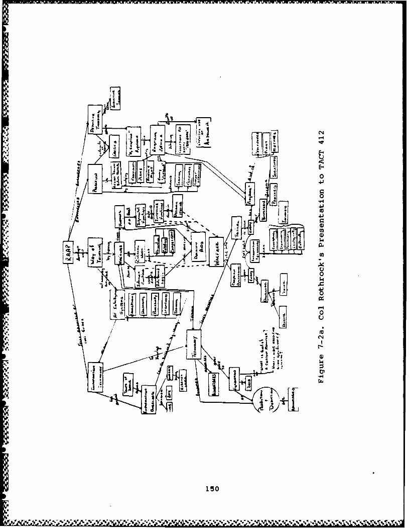
MII
64-
-P4
4 J
4 m1
-- 4
150
Aff. 041 W,-, , .0

.4
41
*1-4
Lit 0
44
7 7J
151,

This was an excellent example of the 'rubber sheet'
characteristic of concept maps.
First interview - Figures 7-2c and 7-2d are the two
maps created during the first interview.
The first mapping session began by having Col Rothrock
list the key or universal problem areas addressed by
RAAP. The Oth area, that of event targeting, was further
expanded during the session. The'resulting map is shown
in figure 7-2c. The second map was Col Rothrock's view
of the process RAAP would take to make decisions. This
map began to show some of the simple elements of the
many decision processes. These decision process elements
became more evident in later maps from Col Rothrock
and others.
Second interview - Figures 7-2e through 7-2j are the
maps used and created by the second interview.
The second interview was a smorgasbord of issues
revolving around the concept RAAP. The first discussion
started by reviewing a concept map made during the second
presentation as lecture notes (See figure 7-2.). The
discussion started by looking at RAAP as a process of
information management. From the view of intelligence
functions, the user is expected to follow a procedural
framework. This framework is called the 'by exception
152
V .. . - •-,V-%. •-.* .-* .-7.-%. %.... V %- V '%'%' .. .' ' •.;•.v% -,%',.V .\•'•'-'". •'%'% '.,y~.

4-4
LUU
14-
4L-
1534

- II
tF."j1
154:

"
t'-S
L~i Vi
L, • L_/
I \,
"U1
1o-U
approach* which iu a management through deduction process.
These concepts were added to the map and is shown in
figure 7-2f. Further discussions on the management
of risk and level of command where also discussed and
added.
The interview then evolved into an extensive discussion
on technological evolution and how RAAP would take advantage
of future developments. In response to the detailed
information given by Col Rothrock, several detailed
maps were created showing the understanding between
RAAP and other concepts.
The four maps address separate relationships of
RAAP and the following concepts. Figure 7-2g depicts
the colonel's understanding of a seventh problem area
in RAAP, western advantage. This problem area points
out the lack of the west's ability to take advantage
of their technological advances because of the lack
of conceptual understanding of their application. Figure
7-2h shows how RAAP uses technology. The concept RAAP
is a thought process that can be done without any tech-
nological support. An example of using a RAAP-like
approach is the Army's Commander's Estimate of the Battle-
field. However, RAAP prescribes the need for technological
application when it is available. Figure 7-2i debates
inductive and deductive thinking and how RAAP uses them.
One analogy to understand the difference between inductive
158

0
C1
tvt >
tit;
IEI
157

40
I I
2-
v 1o
i j-4
I158

RAR
Am -_
Si
Figure 7-2h. P"~cv v& Technology
R9A
159 N~r
Jintr~vM~ wun~na rW Fi Wr r ?W r. a a w a.. nx.-_Wnx.%A .t- . r .*-. -. -wylpVlul V-WUýWUMU6- flrY 'r
and deductive thinking is the fable of the seven blind
men and the elephant. Each man inspects his part of
the elephant. He makes his identification based on the
part of the elephant he inspects. This is an example
of the inductive process. If all the men would compare
their findings and describe the elephant in terms of
each finding then they would be deducing the actual
description. Finally, figure 7-2J compares current
thinking to the way RAAP wants the user to think.
The second interview continued with discussions
on a variety of issues dealing with the development
and application of RAA. Some of these issues included:
1) the level of command and control, and 2) the political
factors involved. One of the discussions centered on
the statement, what RAAP is not. Some of these discussions
are depicted in figures 7-2k and 7-21.
After the two interviews and his limited review
of the initial maps, Col Rothrock praised the process
as very helpful for the expert. *This is a very good
approach. It forces me to deal with and define the
issues in ways that I probably would not have done on
my own.* (Rothrock, 1987b) Thus, concept mapping helped
the expert to deal with organizing his understanding
of the concepts. If this exercise helps in organizing
the expert's understanding, then concept mapping captures
his/her best understanding of the concepts at that time.
180

bftal *4 L
4N.-0r UCmaAy
I Figure 7-2j. RA-AP's Way of Thinking
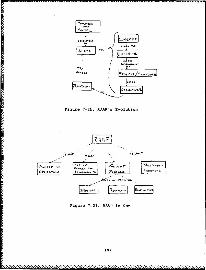
AML
Figure 7-2k. RAAP's Evolution
Fiur 7-21. IAP is Not
182

Third interview - After approximately 10 weeks, Col
Rothrock was interviewed again. The interview started
with the review of the maps shown in figures 7-2a and
b. This interview had several detailed discussions
revolving around misrepresentation from these maps.
Col Rothrock checked the maps for two items. First
he was asked to check the maps for areas of misconceptions
or misrepresentation. This included improper terms
used for concepts and illogical or wrong linkages between
these concepts. He agreed with the basic concepts and
their linkages in both maps.
Col Rothrock was next asked to check the maps for
missing concepts or linkages. He did have some additions
to make to the maps. These additions are shown in figure
7-2m and 7-2n. The last exercise Col Rothrock performed
was an attempt to link all previous maps together.
The result is shown in figure 7-2o.
183

f *g d
'I 2d (Js
'A'
ly.f
18
'O. e1F64

* r41- 41
18

12
.to
~P-4
~044
C.P-
"$40)03
41
.P4.rat
""yvwug'JyAminw
MaJ Harrison:
MaJ Harrison is an intelligence officer assigned
to INYX. He has extensive experience in the operational
intelligence field. His point of view is that of the
intelligence user. Two questions drive much of Maj
Harrison's thinking and were brought out in his map:
- 1) Which intelligence functions will RAAP perform?
2) How will RAAP support the intelligence functions
required in a battle?
4 Only one formal interview session was available
due to time constraints. The approach taken with Maj
Harrison was the two step approach. The problem definition
was emphasized in the first part of the interview while
the second part concentrated on the decision process.
He defined the problem space in terms of the process.
This gave the experiment a new twist since one map would
be considered in both definition and process.
MaJ Harrison's map is shown in figure 7-3. If
one takes the time to read his map, both his understanding
of the concept and the decision process(es) of RAAP
come through clearly.
187
-ý V.. e
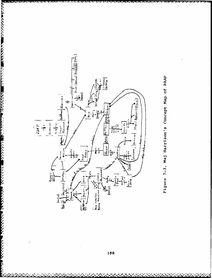
44is uc4
0
"- -I
J-6 -r4
1% A
r•u
ý4
L 241
. . . .. . . .
W-7~ ~ ~ ~ 00 -TO - -XVR.1WTF 1 UU1ZVW VW -. - -- W7 Z-1 -j h- V- r- -- -
Col Kline:
Col Kline is the commander of XOXID on the Air
Staff, Headquarters USAF, Pentagon. XOXID develops
the doctrine that guides the application of tactical
air power for the USAF. He is Col Rothrock's co-initiator
of the RAAP concept. His organization holds primary
responsibility for the development of RAAP.
Unfortunately, due to time constraints, only one
interview was scheduled. Since Col Kline's expertise
is in tactical doctrine, the interview was centered
around his understanding of the RAAP concept. In other
words, the interview sought his definition of the problem.
The map is shown in figure 7-4.
19

li rg w -"1p l.,"]
T4I
-m-,
.21
,2L
1'70
FL • . ,. , ,• ,, . •. , .,%. . . . , % % . .•,. .%. .• % . • ,. .•,% • ,4.,•.,.
Ur John Allen:
Mr Allen is the expert in Soviet maneuver. He
is expected to determine the profiles needed to predict
the red intent from the functional order of battle and
the events taking place.
The interviews with Mr Allen~followed the standard
procedures. The first interview concentrated on his
understanding of the problem. The second interview
attempted to capture his understanding of the decision
processes of RAAP.
The first map, figure 7-5a, shows his definition
of RAAP. Figure 7-5b is the map from the second interview
showing the decision processes according to Mr Allen.
171

-,9
' 2 ." 1,, .- ... d I
SI, z-- 4--'
.: = .! N4-, . j_.: -.L
I: " .1 5. .I4. .
-'•. s4,.po

rwri
'SS4
16 a
ut4
I ~ ad
. ~ 1/ 3

Mr Converse:
Ur Converse was chosen to be an expert because
of his position as a research manager over the RAA?
effort. He is a physical scientist at RADC, Group Leader
and Manager of the Advanced Sensor Exploitation Section.
Again due to time constraints, only one interview
was scheduled. The interview followed the standard
two part approach of trying to capture the problem definition
and decision process.
The resulting map is shown in figure 7-8. This
map is different than any of the previous maps in that
both problem definition and decision process are on
the same map. This was done to save space and to show
the level of conceptualization. In this interview the
* level of conceptualization was not as detailed as with
other experts. The map has two halves. The left half
is Mr Converse's understanding of the problem, or his
problem definition. The right side is his understanding
of the decision processes.
174

4% Pb
40.
('I. a
-S!I
IRE
'a a
175r-

Mr Papagni:
Mr Papagni is the RAAP program manager for Rome
Air Development Center (RADC). Currently he is the
individual responsible for the majority of RAAP research
and research management in the Air Force.
His interviews consisted of both the problem definition
and the decision process. The maps constructed from
these two interviews are shown in figures 7-7a and 7-7b.
Lt Fye:
Lt Fye is also an engineer that is working on research
dealing with tactical sensor fusion of battlefield data.
This type of research is in direct support of the type
of technological applications that RAAP can exploit.
Lt Fye's interview centered on his understanding of
the RAAP concept. His map is shown in figure 7-8a.
Like Mr Papagni. Lt Fye also approaches the concept
like an engineer. He sees it as a *God's eye view*
collection of data by various sensors that feed into
data bases and processors. He sees the output as recom-
mendations and basic information for the user to consider.U
These comments are expressed in his second map shown
in figure 7-8b. This map also shows insight into his
understanding of the concept RAAP and its processes.
178

paa
td I
j0 i1
itil________AV,_
~& *~ 0
14
- -I
d~IE
'17

*� � M �JW LF� LrU If N WU �E¶W 7 N �1 � '�M �Z r�h - N � 17W 1JW � U IrN WU .TU � .. r� � � � E1IX� U�
r
.1*
Ii aJii 1.4yJ
1-4
.3
* 4
178
�S**��* � ' � � - '.j�, �

FAA
I.4,1
a *1
* Ao
'a.
Aa b 4 -a-
40 a.
* I'i
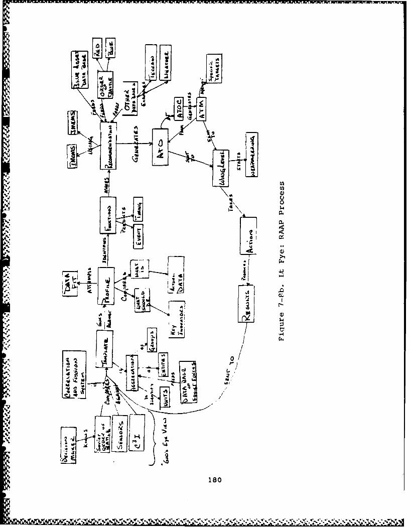
11'0
a-vj
___bp
H '-4
P.~~ i/c CA P. 11VI
4 i o

Col Moody Suter (Retired):
Col Suter is a retired Air Force Officer who is
now a consultant to E-Systems, the prime contractor
for phase I research related to RAAP. He is considered
by the Air Staff as the expert in application of modern
air power against highly maneuverable Soviet ground
forces.
Approximately four hours of interviews were held
with Col Suter. The same approach was used on Col Suter
as on the other experts: to capture first his understanding
of the concept RAAP and secondly the decision processes
as he sees them. Col Suter's maps are listed in figures
7-ga and 7-9b.
Figure 7-ga is the map showing Col Suter's understanding
of RAAP. He has centered it around the battle commander
and his responsibilities. The second map is very inter-
eating. This map is the process Col Suter sees as the
battle commander's
process and the interface that commander would have
with a RAAP system. It is constructed in a time-line
fashion. The center line depicts the progression of
time as a commander interfaces with the decision processes
and decision aids. Thus, the decision processes of
RAAP are captured by looking at the entire decision
processing of the human.
181
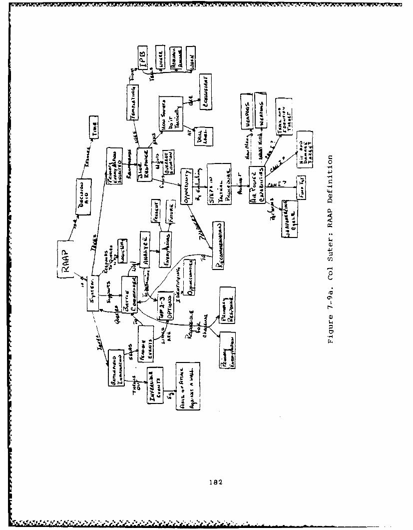
to.
Is
I 'A :
If.
14\:
V, wi
182

04 0
LoLi
44'
>-O
LL
64
- s-
ULLi
183
wow
7.52 Aggregation:
This section's main purpose is to summarize the
lessons learned about RAAP. The procedure used is that
outlined in chapter 3 called Overlaying Maps. The results
of this process are described below.
The aggregation process was done twice. The first
effort concentrated on the definition of RAAP. The
key elements of the definition of RAAP are listed in
Table 7-1. From these key concepts, the aggregated
concept map was created to depict this author's definition
of RAAP. This map is shown in Figure 7-10. This map
was created as a demonstration that a transfer of under-
standing did take place between the various experts
and the author.
InformationWay of ThinkingProactionDeductive ThinkingInformation TechnologyHuman JudgmentLogicDecision MakingDecision Aids
Table 7-1. Key Concepts in the Definition of RAAP
The aggregation process was reapplied to the decision
processes of RAAP. Table 7-2 lists the key elements
identified from the RAAP decision process maps as possible
I 184
kernels. Theme kernels are the areas of present and
future research that will support the development of
RAAP. The main purpose for this list of kernels is
in evaluation of research goals, direction of research
efforts and gaining support from outside agencies.
This list of kernels is not intended to be exhaustive.
It is only a suggestion or starting point for the experts
and key research managers. Hopefully, this list will
confirm some of the experts' intuitive feelings about
the direction of the on-going research efforts. The
list should also initiate discussion on kernels that
may not have been previously considered or acted upon.
No aggregated map was constructed. An aggregated
map of the decision process would not serve any useful
purpose at this time. The reasons for this decision
are based on the main purpose for this paper and the
lack of beneficial use to the experts. It's believed
that the experts will gain more from using all the individual
mappings of the decision processes and the list of suggested
kernels. From these resources the individual research
groups can develop their own aggregated maps of the
decision process and identify the key elements based
on their perceptions. Due to the infancy of the research,
a broad view of the possible decision approaches is
needed so research efforts are not stifled by single
views.
185
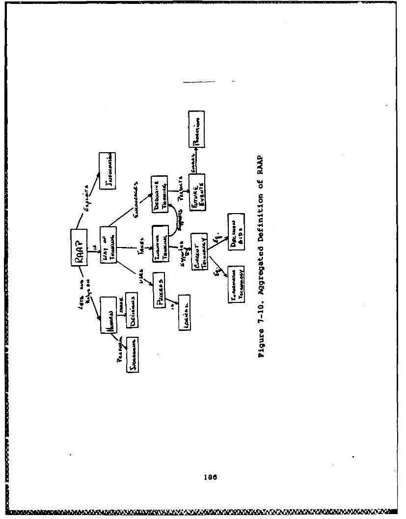
'Aa
I-S

Information Processing- Collection of Information
a Who or what manages the data collection equipmentand procedures?
a What is the specific information that getscollected?
a Who or what mechanism selects informationto collect?
a Now is the information ranked?M What are the *rules" for:
1) collecting the information2) identifying pertinent information3) ranking the information4) eliminating the information
Collation of information* What are the 'rules* for:
1) combining information2) establishing meaning to individual
pieces of information3) not combining information
Fusera What are the *rules' for:
1) drawing meaning from raw and collateddata
2) ranking the fused information3) praeenting fused information (order)
U Where does the information get fused?(central vs local)
a Who gets fused information?- Displays
a Now will the data (raw, collated, fused)be displayed?
M Who will get/control the display?a How will the Battle CC get the information?
- Data Base Interfacea Who or what controls/maintains/accesses?a What are the *rules* to control/maintain/access?
Red Inference Engine- Profiles
What are the "rules" for:1) matching current events with past actions?2) handling the uncertainty?
3) ranking the importance of the predictedactions?
Table 7-2. Possible Kernels in the RAAP Process
187

RED Inference Engine (Continued)- Data Base of Events
a Who or what will maintain/control/accessthis volatile data base?
a How will the CC maintain knowledge of data?0 How will the CC access/display logic for
prediction based on intelligence?'Opportunities Identifier
a Who or what will notify the CC?a How will the CC be notified?a Integration of Opportunitiem/Options/Intelligence,
how will they be displayed/managed/communicated?
BLUE Inference Engine- Data Base of Actions-to-Take
a Who or what will maintain/control/accegsthis volatile data base?
0 How will the CC maintain knowledge of data?a How will the CC access/display logic for
prediction based on intelligence/Pr*edictedRED action/Resources?
a Integration of Resources and BLUE options?- Weaponeering
a Optimization of Force - based on:1) Weapons available2) Tactics3) Target characteristics4) Survivability
"What-1f"a Who will control the function?a What functions will be contained?
1) War Gaming2) Simulation3) Other Optimization and Gaming Models
U How will functions interact with the currentinformation available in the system?
a Display of results?n Who manages/control/access displays?a How do results from "What-If" integrate with
actual data displays?
Table 7-2. Possible Kernels in the RAAP Process(Continued)
188
7.53 Observations:
The following discussion is a record of various
observations made during the process of preparing the
concept maps on BAAP. All of these observations support
the concept map as a powerful communications tool.
Three observations are made based on the fact that
each expert brings a different perception of RAAP into
the interviews. Throughout all of the mapping exercises,
one thing became very clear. The experts defined RAAP
in terms of their specific backgrounds and from their
perspective. Experts approach the problem based on
their backgrounds. Col Rothrock looked at it from the
theoretical level of information processing. Mr Papagni,
Mr Converse and Lt Fye centered their discussions around
the process and the hardware. Col Kline's view was
from operation's need for support in information processing
and the advantage of RAAP in this problem domain. Maj
Harrison's point of view came from the operational intel-
ligence field. He was very concerned about how RAAP
would interface intelligence with operations and accomplish
the intelligence functions. Mr Allen took a totally
different view by describing RAAP as a planning system
that is mission driven. This makes perfect sense since
Mr Allen is the Soviet expert and deals in-depth with
the mission assessment portion of RAAP. Finally, Col
189

Suter took the approach: *If I were the commander, how
would I want the decision aid to support me?' (Suter,
1987).
From these varied perceptions come the first obser-
vation. It recognizes the fact people do have differences,
but still the series of maps show a high level of conceptual
agreement. This phenomenon demonstrates that a universal
understanding of basic RAAP concepts does exist among
the experts.
The second observation substantiates the basis
of the overlay process. The many perceptions produced
a variety of maps which emphasize different parts of
the RAAP concept, but each expert identified most of
the same basic concepts. This made the overlaying of
maps an easy process. When most of the experts agree
on the basic concepts and link them in similar manners,
confidence is high that that concept is key.
The final observation made from the variety of
perceptions deals with the transfer of understanding
to others. Difference in background and development
of thought patterns do not alter the transfer of under-
standing. Linkages may be different and organization
of the concepts may be radical from map to map but the
basic understanding of the concept still comes through.
For example, contrast the maps of Mr Papagni and Col
Rothrock.
190
The strong background of scientist/engineer produces
a set of maps that show the powerful influence of systematic
analysis and process. Especially noteworthy is the
way Mr Papagni described the process. He has it organized
in his mind as a flow of inputs, data bases, processors,
and outputs. This approach is quite different from
that of Col Rothrock. Yet, the overall concept of RAAP
is the same and many of the linkages reflect similar
understandings. The educational value of both sets
of maps for the novice reader enhances the transfer
of information and eventual understanding.
Finally, one noteworthy incident was observed that
supports the value of the maps as communications tools
and transfers of understanding. After completing the
second interview with Mr Allen, M&J Harrison entered
the room and looked at the map that was still on the
board from the interview. MaJ Harrison was able to
quickly read and identify a mistaken concept Mr Allen
had of the Air Tasking Order (ATO). After a few questions
and some explanations. Maj Harrison suggested changes
in the map that would more correctly depict the function
of the ATO in managing assets.
This incident substantiated two propositions of
the concept mapping technique. First the incident showed
the ease of readability that is inherent in a concept
map. Maj Harrison could easily read and pick out the
191

understanding depicted by the map. This action of Maj
Harrison is evidence that a transfer of understanding
took place. Secondly, it showed that two individuals,
having different beliefs about a concept, could quickly
identify and discuss the issue by reviewing the map.
After an agreement is reached, appropriate changes to
the map occur which shows the corrected understanding.
These were just a few of the many observations
made that support the power of concept mapping as a
communications tool.
7.60 Conclusion:
This chapter has recorded the application of concept
mapping to a large problem area. Its goals were to
bring about a transfer of understanding about the basic
concept and to help identify key decision elements in
the various decision processes. The chapter explained
why RAAP was chosen as the test bed problem area and
gave some background as to why the USAF is very interested
in RAAP. The experimental procedure was outlined and
results reported in detail along with the entire series
of concept maps.
In conclusion, this experiment has shown that concept
mapping can act as an aid to pick out key kernels, help
.enhance understanding between individuals and do these
192

things on a variety of conceptual levels. Recommendations
regarding the results of this experiment are expressed
in the final chapter.
193
Chapter 8
Results, Recommendations, and Conclusions
8.00 Introduction:
This chapter discusses the overall findings and
results obtained from applying concept mapping to the
task of problem definition and kernel identification.
Based on theme comments, recommendations for future
research with concept mapping is presented for the technique
development and application. Recommendations are also
presented for the future work yet to be done on RAAP
and where concept mapping may assist.
8.10 Findings and Results:
The main objective of this research effort was
to develop a user oriented tool (concept mapping) for
problem definition and kernel identification during
the design phase of a DSS. The second objective was
to develop a procedure for using this tool in the adaptive
design approach. The two sections below record the
findings and observations from each of these objectives.
8.11 Concept Mapping as a Tool:
Through the observations made during the many exper-
iments, the findings can be broken down into five separate
areas. First, concept mapping demonstrated its ability
194
4.

to transfer understanding between individuals. This
was especially noteworthy where more than one person
was involved in the construction of the DSS or defining
the problem. The fact that concept maps transfer under-
standing is also why they are an excellent teaching
tool in education.
The second finding is that concept maps identify
inconsistencies and misconceptions. If a person is
erratic in his/her explanation of the problem by using
different concepts and illogical or multiple links,
then these inconsistencies are readily seen in the maps.
The person can then concentrate on the actual meaning
and form the proper understanding. In other words,
the expert stabilizes the meaning. If in a group setting,
one of the members has a misconception about some part
of the problem, it will be seen by the others on the
concept map. The members can then help the individual
attain the correct understanding and eliminate the mis-
conception.
The third and fourth findings are the most important.
Basically, concept mapping works. It is shown in the
many examples presented in this paper that the concept
maps: 1) capture a human's understanding of a specific
problem space and 2) capture his/her decision process
elements. This process can produce a reasonably complete
description of the problem space. It creates both a
195

perceived definition of the problem and a list of tasks
and events that make up the individual's perception
of the decision process. Understanding depicted in
these maps in easily transferred to others by 'negotiating
the meaning'.
The last finding is the forum for 'negotiating
the meaning' that concept mapping provides to the DSS
design team. Concept mapping provides a forum for discussion
and evaluation. Using the concept maps to capture their
understanding of the problem space and elements of the
decision process gives an easy-to-read format that is
simple to manipulate as perceptions change. The design
team members identify and rank the "importance" of the
elements in the decision process. Once they have the
rankings and initial system requirements, evaluation
criteria can be developed to ensure the design supports
the kernels.
8.12 The PDP as an Integrator:
Three key observations were made from the two exper-
iments using the PDP approach. First, the designers
had an orderly approach to guide them through the analysis
and design phases of the adaptive design. Each time
they complete a step or an evaluation in the PDP, the
next action was clearly identified. Second, the criteria
for the evaluation of the system requirements were much
190
4#
easier to derive. The evaluation had a purpose: the
need to support cognitive processes which were described
by the concept maps. The evaluation also had guidance.
The guidance came from the kernels identified as the
key decision elements that required the support of the
DSS. Thus the criteria derived ensured the system design
supported the cognitive process and was built around
the key kernel(s).
The last observation was the increased confidence
the design team members had on the system requirements.
Using the PDP enhanced the design of the system to support
the cognitive processes of decision making. The concept
mapping tool aided in the identification of the kernels.
The feature charts and storyboards developed the system
requirements based on the kernels identified and the
evaluation kept the design on the right track. All
three steps made for a set of initial system require-
ments that were believed to describe a DSS that really
did support the decision maker.
The examples and personal experience of the author
led to the belief that the Problem Definition Process
is a viable method of developing and maintaining the
system requirements of an evolving DSS. The steps contained
in the three phases of the PDP have produced two interesting
and successful designs and prototypes. The more DSS
designers experiment and work with the order and iteration
197
of the steps, the easier it seems for them to determine
the requirements and alterations needed by the system.
8.20 Recommendations:
All of the recommendations presented below are
for further research and study. The recommendations
are broken into three categories. The first group looks
at proposals for improving or enhancing the concept
mapping technique. These are mostly nice to have ideas.
They came from the fact that current concept mapping
is a lot of paper and pencil work that is tedious and
repetitive. The second group of proposals looks at
further studies that would apply to concept mapping
in different arenas. The third and final group of proposals
suggests ways that the PDP could be enhanced, used,
and evaluated in different ways.
8.21 Technique Enhancements:
There are three areas recommended for future study
that could improve the ability of analysts to perform
the concept mapping technique.
8.211 Harness the power of Automation:
Tools such as the Macintosh with MacDraw need to
be explored as aids to concept mapping. These tools
could be used to initially build the maps in the interview,
198
store the maps, make quick changes, formalize a map
for presentations, and perform 'What-ifs' with the links
and hierarchial arrangements. A study could also look
at the peripherals to the computer, such as: larger
screens, light pens, multiple colors. Software enhancements
could include a study on the value of animating the
concept maps. This animation would be the evolution
of the concept map as it was constructed. The study
would explore the value of the animation in transferring
and negotiating meaning.
Automating the maps would allow the maps to be
'overlaid'. This would mean matching key concepts from
different experts and physically laying one map over
the top of the other. With the maps stored in the computer
the manipulation of concepts would be trivial. The
differences in linkages and meanings would be highlighted.
The areas of agreement would also be highlighted and
further justify the evaluation of concepts as key kernels
in the problem.
One final recommendation for follow-on study is
to build a portable tutorial program to teach the designers.
This tutorial should include all of the lessons in Appendices
A and B as well as a complete walk-through of the DSS
development with hands on experience. The lesson would
be targeted for the user, so he can design his own systems.
Basically, it takes the middleman out of the DSS develop-
199
ment. This would leave the professional DSS designer
the time for consultations and larger projects.
8.22 Concept Map2ing A&Dlications:
There are four areas of study that could be continued
based on the application of concept mapping to problem
definition.
8.221 Apply to more Problems:
Concept mapping needs to be applied to a wider
range of problems. This thesis effort concentrates
on the problem definition for DSS development. Concept
mapping can be applied to any problem domain that requires
the problem solver to define and describe the problem.
However, procedures need to be established and experiments
performed to prove that concept mapping can be applied
to any problem domain.
8.222 Concept Mapping and later stages of DSS Development:
Further research is needed in the later stages
of DSS prototype development. What role do concept
mapping, storyboarding, and feature charts play in the
maturing development stages of a DSS? Does concept
mapping help dampen the volatile effects of major changes
in system requirements?
200

8.223 Follow up with the RAAP problem:
There are two areas for continued research in RAAP.
First, the full set of concept maps need to be reviewed
again by the experts and a general consensus established.
After the agreement of terms, descriptions, definition
and process elements, a list of kernels needs to be
developed. This list of kernels can then be evaluated
and ranked in order of importance, feasibility, etc.
This action would result in a setting of research goals
and Justification for financial and political support.
The second emphasis would be in developing a briefing
tool out of the combined concept map of the problem
definition. This map would become a finely tuned
communication tool for use by the Air Staff and others.
The inherited ability of concept maps to present informa-
tion in an easy-to-absorb manner would make the presenta-
tions to novices much more understandable. After all,
concept mapping is an educational tool for negotiating
meaning and transfer understanding.
8.224 Apply CM to the USAF Accuisition System:
Further research is needed to find if a concept
mapping technique is feasible in building a management
scheme. Specifically, can concept mapping be used by
the Air Force Systems Command to manage adaptively designed
systems? What would be the procedure? What evaluation
201

criteria would be used to compare the many kernels within
a system? What evaluation criteria would be used to
compare similar but different system?
8.23 PDP Enhancements:
Almost the exact same recommendations for enhancing
the concept mapping technique can be said for the enhancement
of the PDP. Automating the feature chart and storyboard
steps would also aid the designer in the process of
determining the system requirements. A drawing board,
on which s/he could quickly create the feature charts
and storyboards, modify, rearrange and save them, would
be a big time saver as well as a big boost to creativity.
Evaluation criteria on the human engineering aspects
of the DSS man-machine interface could be built into
the drawing board. A system of this nature could alert
the designer to a variety of faults or recommend a better
idea. The system might offer some of the following
information.
1) The printing is too small to read.
2) The colors are too difficult to distinguish
3) The DSS should have an attention-getter.
Example: Flashing light - red in color.
202

8.30 Conclusions:
This paper has explored a broad range of topics
and issues. First, the decision maker's environment
was described. This description showed the world as
a mass of fused communications bombarding the decision
maker constantly. From this onslaught of information,
he must identify that a problem exists and then attempt
to define it in full detail so a DSS, if applicable,
can be developed.
Second, the theoretical foundation was laid for
why concept mapping would work. The way the mind stores
information and the way concept maps capture information
was shown to be consistent. Based on this fact, meaning
and understanding would be represented much more effectively
than with any other method of capturing knowledge.
The next two presentations were "how-to's. The
concept mapping tool was shown with two self-paced lessons
and helpful hints for interviewing. The PDP was then
introduced and explained step by step. All of these
steps and lessons were designed for two reasons. The
first reason was to establish a standard approach to
the problem of determining the system requirements for
a DSS using concept mapping. The second reason was
to teach the reader and future designer a successful
way of designing and building a DSS.
Finally, the paper presented eight months of exercises
203

where concept mapping was applied. A broad variety
of problems was sought out and experiments were run.
The successes, small and large, were all recorded.
Although concept mapping is a simple tool to use,
it is powerful in its ability to define problems and
identify kernels in a problem space. Some further trials
and experimentation with the method of applying the
tool need to be done. But the theoretical foundation
and its current success points to a new approach to
understanding problems.
204
APPENDIX A:
Introductory Lesson to Concep~t Nmanping
em CO
LI... ..
-aea
-~ C=1 40J
C-~ IL
LJL7
CLL
_ 205
.... .... O i
i~~~- r- ---. -- -
Iro a-
I.- Il I
WIf -. - -
I-r M -
Ie %
I ~ ~~ i --cu I cuue
en I
r Ii L --
C3 N a .oft: I
II .jj 7
s ~ a -a.' r
a -a -206

IIZA
I.lk -0 Li I
Is I
I II
I I .4-, II I -C II I0-I I M
I I 6I
I 207

~~1=01=0 -l 1= I 00 = t-
=n = :=Ia
52-7 -I-
__i -z Wi.- oo -L X3
0 j
nai arr ~r I= r -3r E
E~~J *~ aJ -Lin
4, -~ I-I
0208
cu
Lun
Lin
r-
baj
r I a
aa)zi.
1=~
o 209

=3 cJ
cu
C Lin
l mi e. F
0.' a.'=
0.1 .c C-- ____
I..' a.'I-B I*a.' Iu
C c~:i -
o r~i C
210I
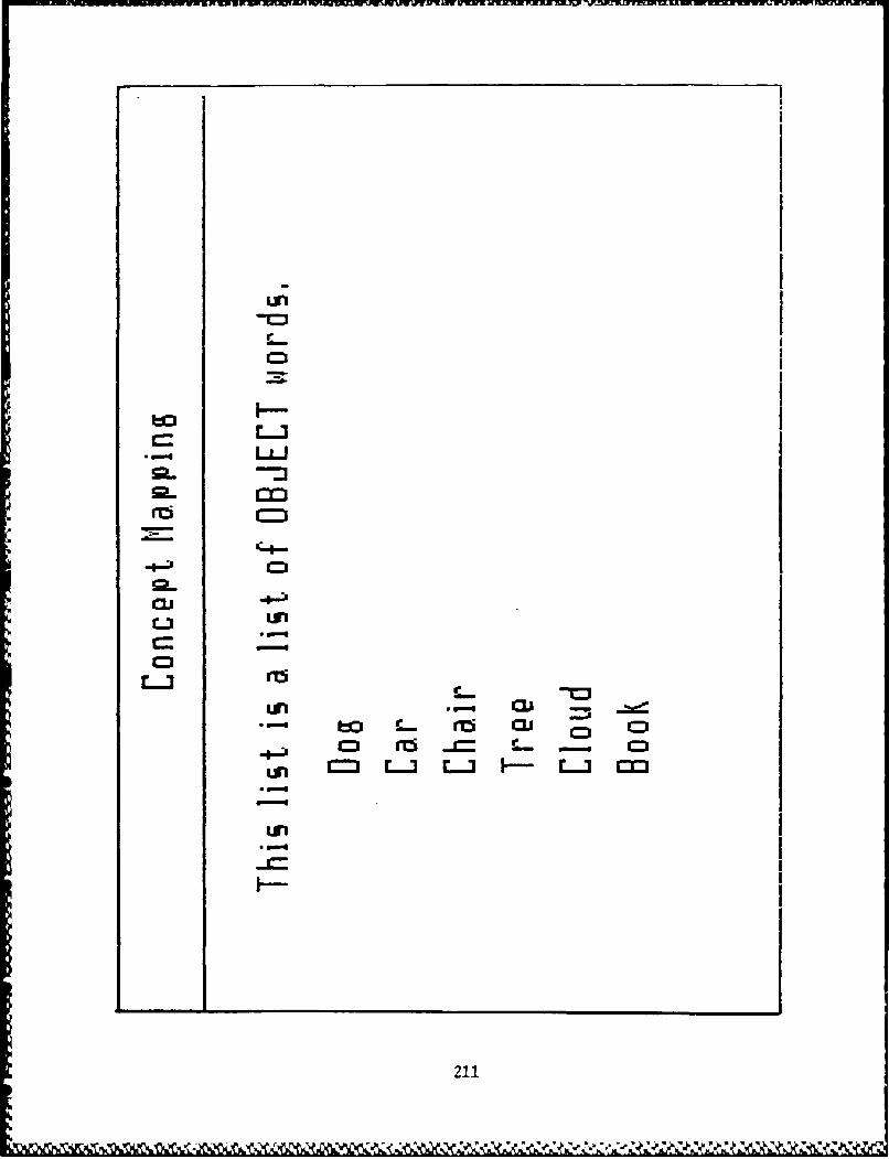
too
L-3
rcJ -#-;A
C .
Cij r-~ C - Ciun C= La I -L-3 rIcD
F-
211

a'
1=0=
rlrir= 1=
rM-'
SP-. un_
.-u
un~ a.'C= ''-=z -
L- emi
L) CD .a.! CL
C= - .=
~= OJ ea= -=c~: -~ . -
212
1=0
-o
c _ C3
LCD
2o C3 c
r~i un 0.
_ 39
CD
r-3 ro 0.1cu CD
0. D CD
121

-Zn
-ci Lii
-jj a1I-c
to to cir C CJ
C-4
ni CD
C3
cu -= ci c
L-3 4.-
0.1 rri -i
s X
r-nr- .-
L - I
Lii ~CDi
O21

II I II 1 1I I II I II 1 1I I _______ II I II I IIIIIIIIII
IIIIII
I . II. II __ I
II II �- II .- II .� II �- II - II 1I -�
I �-,
I II Ci II II � II * I
I 1=1 1I pq II II I
* I
I
I II I
I I1 1I II II II 1 II II II II I
I I � I
2.15
S

C -
___ aj0.1Lm
bo un C
cui-b W
C0.
L.).
r 'I-
rci c-
0.1 = - u,
ob 0.o-
0 r216 '

un
-L
rci _lto = bo a rizi
a= aa 1= .
rcai i:: .. c
Cl -u- c -
L217

COLD
to CO
a)to ri 3
cu n rj
I-le
aJJ Cs r11 _
06 P"-la-
0l U
0.'
Sm LLL..
-~ -- .'218

a)
rcJ
CI.
zif
1=~
cu cu Li
Cl nz0L-3~- C-
rci 0cu cu
D... -
ri >Cp a --
in'
219
-%
naiLfI 1=0
- CU
CJi _M rca.. CE un
aj cu i
9- ci e-J
riiý -C .
-~ L)
C.'l
nri r- ua C.
_ E
-C u C.C3
Liii
Cl220
L -3. 4 un, - -
u ~ -

II I
aI II I
I I
I II II II I
I II II I
I � Ia �I - 3
I �- II .* II *�-* II�- II - II II -�I .- � I
I ,- II - I �I � I
I �
I II I
I II
I I
I I
I I
aI II 1I.
221
4
- � .�'-* �
ciu
--- Ca
-r zLP= -- c p1=
a)C
-c ci aj
cn:i a)
-j ciSP un LM ~ u-0-
-~ Hz . - r- c
nr' M. C.))
aCa
Ca CDL-3 c m:-CI.u C-.
C- -F 1;s r-
-. ý 4.P
Cu 222 a

C-)
ui
CI.
Lii
CD cu
rrC.'
CJ Ca
r I
Lfi 223

aj r
S
-S
I. -c
cu cu
... aJ ci C
a nr i
cii _j r
Cl cum4-. Q-- CI
Ci un -c C
*u -%-c
cu "I-
-S Cl r- I
rai C.'it
224

i in
I inel I un
v_ Im. ITSI
CL II I ''
am I cI*MR I cm_.W
I-
I 1 r -I I - r~: - -
ere I
I I I'.S- .4-
'I I -- m-06 L6I~c CZI -t
I I - -a
4~~U I - L -
I -Ir~, _"225
sp-I
nzi to'Su
-S-
CJ
226

.0-
a.
Wzi_ (-I)
- aJ 0
zii
c~:i 1=
-I=
rci 7cu c=
L)J
cu:
Lu3-I
227
IL
I M I
i inI -j
I gem%
I I I
I 1 - I
I I *ED
I I -228

,azausna~~wrwr~~ar~arwns -l -. -lra -f -a. l fn~ - - -. -.---.---
LU 1
cu
c-J u
cucho unCD -;.
curizi_ a.-n
7Q aJ 4-'
0uu
riie._= a,
-~ LSC.-IL-3a
C, CJ LI
C-1-
o Lii
229=
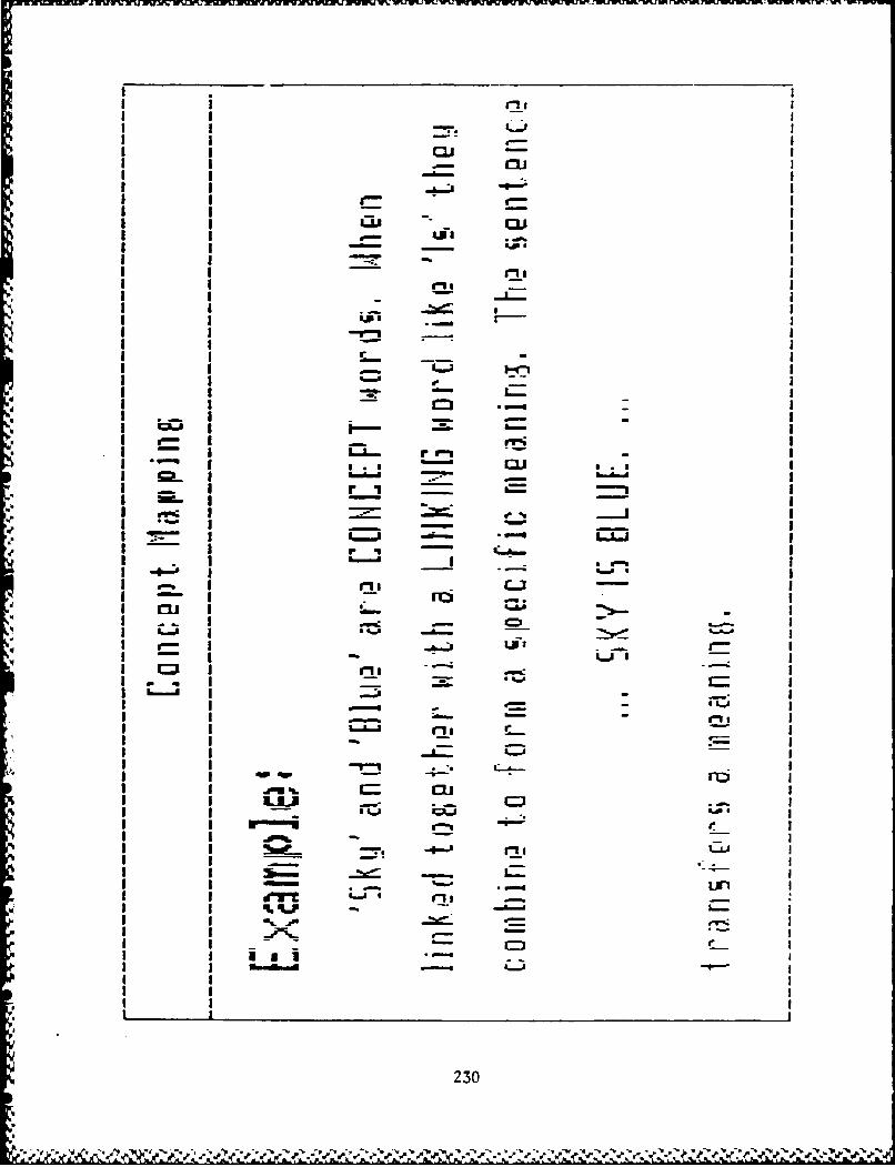
II cu
I I _ll
Q60IJ9- -
I L I UI I - I
I I LP
*~~ I a-1* I II-I'
* I I I-
Iin II IL
I I -L
I I - ~ 3-I,
I I I 230
I I -U, If

I~ inI
I in
GI II I -cI
I erg;Lin I'
s inI .- 4cI
I -. 2 31 9
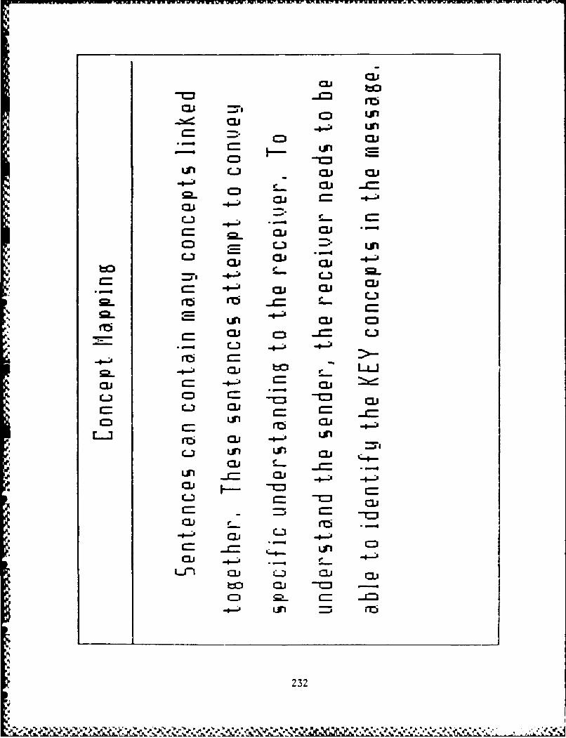
ci -u
'is'~c C..1- J .-IMnr0.' un
a i 1= -
CJ a)rn
C= aJC.
ai -#a.
aj c.
-j f.-. (.3 .a -
C . a
un (.3 Ccia us'I-
aj o=
E-3 TI u
nCi cu --
* 4- un s c
usc'
C232

rwi
aa
r.-
cii a
r. in'
a_ -@- 0.
n~i m ai
cu c cu
0. 'I5'
sp-
ciu
LflI
a's 35233

rc
# °a
, .P.i
• Lin "&-;l
I - r5 2-I .- --,I ~~ d'sitW
i0
I I 234

Fen s .I~falM'1 ~ r w.,W -- , -XUMMU~ J ' Iw~ .U ~ L t . .,S.a a .a- .
I 16
ao I
C- I7
I L II I I
I3L I I
I - 1 1ai I u'
I I r5

I I'I_..
1 "1 1 1 ,•,-
I ~--p
I I•
I --
I I
C-I-
a))
a~i boUoc
:3) 0 --
-C)
237 J

IXW FI17 LIM)
I I .-.
I inr- I- I
bol P%0 e-JI~l I -ia -I I -. --
Ii I w-
I I -~ -un
I IWO
I I -
I*Ir
IU - -=~
I ~-'I - ~ e-"
a - .~.-~ I'- U
I *~ I -238

APPENDIX B:
Storyboard and Evaluation of a
Decision Sunnort System
STORYBOARD AND EVALUATION
OF A
DECISION SUPPORT SYSTEM
Submitted To: Lt. Col. Valusek
By: Capt Bivins and Capt McFarren
20 February 1987
2)
i 239

STORYBOARD OF A
COMMAND AND CONTROL
DSS
Introduction
This paper contains the storyboards of the DSS for the command and control of
theater nuclear weapons. The storyboards are meant to be the basic displays that a decision
maker would see in a theater command post faced with the decision of when to authorize
the release of theater nuclear weapons. The level of the DM that this storyboard is designed
for is the highest level in the theater (CINCEUR or equivalent). This set of storyboards
would give the commander the "big" picture of the situation, climate, resources,
constraints, and tining required to make the decision to release nuclear weapons. The
storyboards were created by conducting a "problem def'nition." First a "concept map" was
done for the problem, then a "task analysis", a feature chart, the storyboards, and finally
the evaluation of the DSS. All of these steps lead to the identification of kernels, two of
which were identified during the "concept mapping" and are highlighted on the concept
map. The next few pages show the results of the "concept mapping" and "feature chart."
The "problem definition process" is shown below.
Problem Definition Kernel
Feature Chart
Flag Concept Task Data Storyboard EvalMap Analysis Flow
Time
24n

CONCEPT MAP
to give .not first use tey thinkingnoC mlt
Risk~~no RedSotk avnaeNtufficient force
Win War is Ady Considerations wee tl ogtr
m st be Condemnnation Do ohmrlae eed fet
Initiated Agtm oafc aaeitn
Mtd StoredW
sh ul be av4 Concerns
tac nuktt-
CiA CW~optioCn

U-. ~ ~ ~ ~ ~ U u.*WfS 5l -
wj UJ
ac

RwtwVf~ RaWWvmMW W wrv ,;T w - " r ruw v lj.
p C - 4~&n
- .E
-W )
U - .C7R
~ C<
~ C CV-
> 0
z C4
Coz QV2 0
cu P
u <=
00
>. >
q- E q~
o 0 C9
cuZ
UU--
* -~ U½.E
U CU
2 ~ V2ii. ti 0~ E'a- - ..
~ 0 0 43

U) cu
L. ~ 1=0
cu -I-. Faj i:~
4244

C-) 0
c~. 0 0. C(0 0u*
>. 4 ~ 0o C.) U U
> 2~U (
I- CA
44
uC
0 EC 0 *
(4 0>
7ýC >
'24

I.'41-I
L&In
ews-n
Im
ee246
%t

0
4n 0
> I-
.9 . 4. 0
cc0 0 C-
00
E r-
Cu C _
cc .9
cu V)
.0 0
U 0 %=E
1-. cu
*~ u 0 ~ .
>. U. CU 4. .)uu - * r-
W) a- .
CO~~ .0 V) UU
0 9uC4. 10 c
r- -(0A
U) U E
r_ 6. .In 0.0
CU~~ ~ 0 0 ~ &
Co Cu c .) C
.v.. I.-

4"
V -
=
*1
=.1 _______________________________
- � I.4., . - - .
5-
.5*
-S
-. . - e -
a - -.
S - , -*1:
' !.. 344 - ,r�C:'.S'z -
U . . - - . ..5 - PA.. P:5 C -:'V
t
'4
5-.
5-,
5-'
tIt' - - -.-- . --- -
t - - - --
II,
U, -. - -
9' i -
* 248
4%

6. -
20
C 0 C
C~ 70
M-4U cu#

LAJ
LLU
aL&J %
C=
C- P5 -
-Ss

m cc
P.- .- CLCu 0 4 1
CO cc) u
co u
'-I a .-
Ur >U, -E
LMU
E UE * F-
Cu Cu .
_ PC
Co - . 251

4A
Lai,A--
3==I.-,
4:o I I I C. u
_
I I
-
I J I-4
- I I I I c~I I I I -4
e --- Ip 0..
252I

Es'C
ECu
-�
Cu�-� U
-o0 0 Cu
A - C-, -�
Q -a-
- U
00
-� 2 2z - 00U a-o
o- .� S a
0C,, -� Cu .0
o 0 U,
.0 U, C00 4.)
z 0- U0 0 C
U - Cu- a- 0 U
* .C 004.) - -* .2 C C0 0- C CuCu 0 C-' U
U' -�- - U
Cu .0Cu U'
* '0Cu .C CC..) - Cu
a-U ob4-) C *0
0 C14.� � .�- U, U' Cu
Cu -o UU *� IU' -C 0 .0 U- .-
U� -.- Cu* -C C/*2- - .� z C
C-) rd, 0Cu C -
E.. 0 OH CuU' _
0
-oCCl0 z 0
a- -
1.) -� -�
I I I
253
� � �*�* 7� * I'
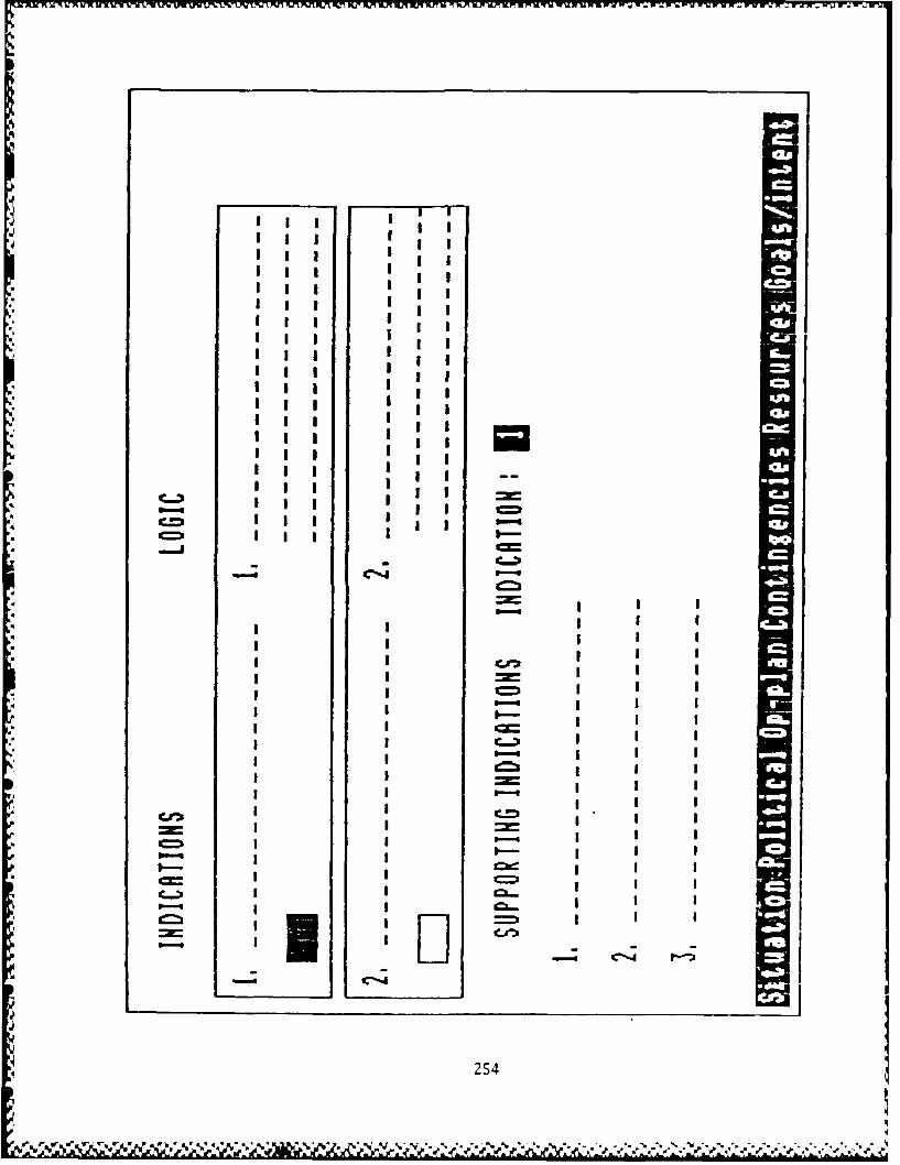
I I I I ' 'IIIII IIII III IIIii I -
IIt
III I II
* III Ihg III
* III IIIIII IIIIII III IIlii IIjg II
* III I -
III IllI I I I �Iii IIII I I I � --
C-., III =I IIII I -
_ II -
* I I I I
=-
I I
I I =
.4 I II I
I I __
I I C-� I I I -
I I -
I II I -
I I __ I.
= I I =I I -
* ______ I I ______ I I I -
I I �-
- I II -
-
254
.4= I* V* W r V .4 *- � ****�*- **.*. �

.5".
4, .0
o o-
0 0
E vC
-n o
255C
-o.0. ~A !U

LAJ -=
C=)
L&J~
4 ~= -
* Me
06.,I I I I
:PCII I II I I5
- II I I I256

.04.) -
.0
- Coo 0 -�
4.) -HCu U
.0U)
* - C
q -C4.) C-
2U)
0U� UU) 4.)CU 0
4.) - C01..0
C I-
F.'CU 4.� 4.)U .0 .0
- - -U 0
-. CoH C
- 03 Cu
oCL]
I-. .0U 0 -
�
-� 4.)Co �C 0 i�.j
U F.-U)
Q �.- .0 .- � 0UCu L)
CO
.1 0 0U) .0U -
U) Co -U) C UCU� 0 U
M C UU)C#2 . U)
- Cu
CUW�2 U
.� < .�
.- �. U0 4.)- .0
H
C .2 Z E� �
� L�.. -
Z H -z S2 E
o 2 C =- E < -' -
257
.A .$ J -�

r a-
X- LL - -~
9''
I 228
% I

:4:
)z
W-4Q..0
o4E:
00
0 •
"-(J• °
- .'
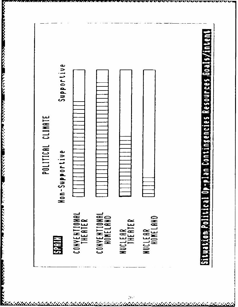
31=1CIo
-J-
.5. C=I
CIk
C=LAJ LA.J0- o 9-- - - P-- --
I- LJ _= 4 - cx_ 3=
LAJ LAJ- LU =h_

' 'A
U -UU.-•
U- 0
C -Z
SU Z o,
• ,--.• •
b(
U. ..- E".,
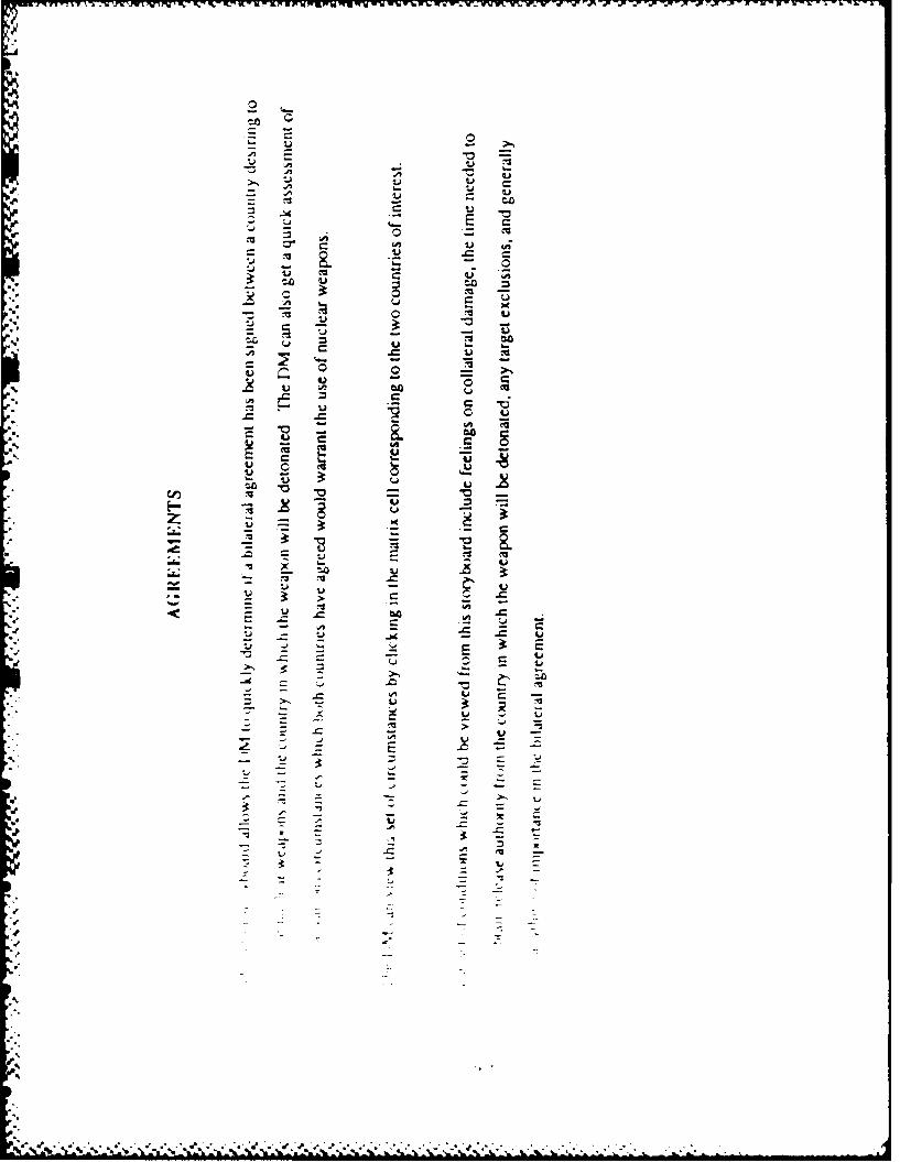
0-
�o0
- U Cu-I U
U U U-A, b�. U
- -A, U - U- -
Cu U� -'-A UU -
V Cu � 0 - Cu0- � U ui
- U -� �
U U CUU U �n
- �.o z* -� 0 Cu
S. -� U E �- Cu - 0 Cu U
U* -
p -� - -S. � Cu COb.. b..
0 o -
-� � U - -� �Co U CU
Cu U �0 U
S. - - - CO
U u -�
CU *� - -� -
U -�z U
- . - -VCui- U
U U
Cu� -� -� Co
- - U -U - U - -� - C- - - -� - -� UU -J �. � 2
- - C U- - U
-
U C -
U � ;- - U
CU
- -' -�
-� z 2-S - -�
- U -�
S... - - -
- SU -
.1� 5
5 2
A'A'
S.
*45
.5
..-.-..- *..-..-- -... -*5*>.* 5 5 5 S S *% �-�% *', * S ** ** .- -. ...--....c.....
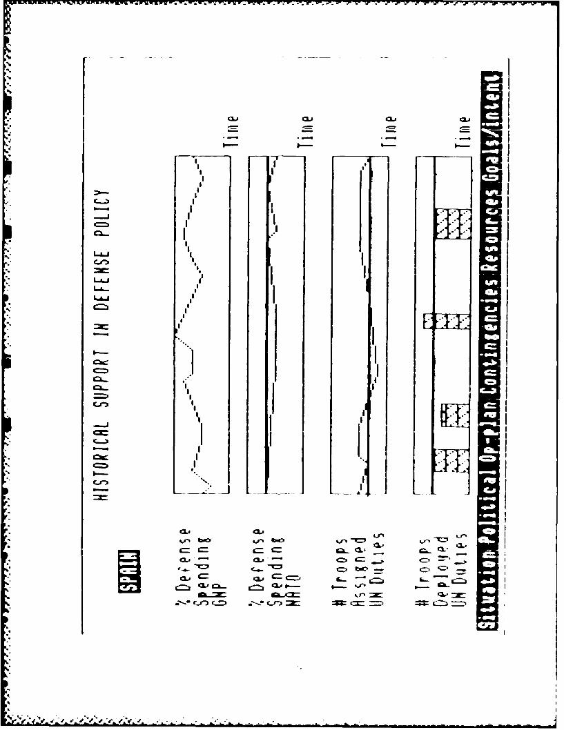
C_ -36 42.
qw I
I, 1Itwo
IILIA I -
QLA 4M S

LIMI
1= *Mo LAMJ L." LU L
LU _i
3= C
L-"I
L.A.
L.AU
L.AL-J L-- -
C02
0
E
C4C
4;.
.0
Z,
4;
10
p0
C-4n
26

A�J AMF.AI�M '.MAK AZRM� MXW1M1(11��)Q7'�IJVJX �4 L'�� �J'. .N .r)( VW IrK �t � irK v-K � IrK UY � - �
4
I
- -
-4
�.1 �qf-I
I I I II I I II I I II I I II I I II I I I
I I I I -
LJ�J I I II I I I
I I I IL.i�I I I I
I I I I
___ I I II I I I
I II I� I I
-� I I I II I I I
-� I I I II I I II I I I
I I I I
I I I I
I I I II I I I
U I I I II I I II I I II I I I
S-i I I I I-� I I I I -1
I I I I
* I I I I -
m - -
S. II266
5- 'S � � - � %* %S . � �.. S S 5' ,�
5 �-v*,

:)l
icn
- •.
Cu (Al .
°U •
J 0 Cu -
UCA
= - 2
c 0 U.u
CC
*~c Cucu
(U-
267
U, >.*
" " •,•" " ,•'" "• -,•', 'v,,,, •" ,," ,,' '' 4 •"•" ," ," ," ," . ." ." , • - . .- • . ." ,- - . ,,,- .- " . .- o" t•,-,,
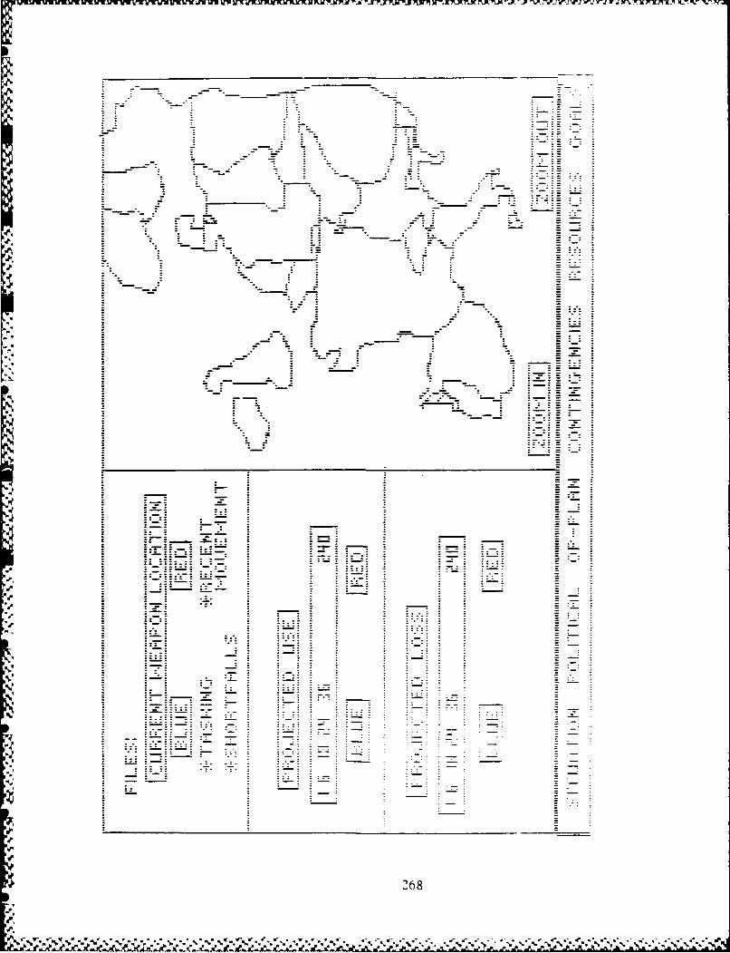
A.1�
.9.
-U
-U
-5.
A
*9I
-'It'
I'
-'9.
S.9.
S.
1%�'
3%'
1%
J-p
S.
S.
268
-S'I
S..tcr.r.�..w.%w......� * � � .* ,t&.�-* �
.t .P ..K P � .JLA P. .. J..P d. � �-a"a� _ �"2'.st. �

LLII
(A C C1
~~1 0 u-
ca 00 SUcc VU .0 uC
CA 0 - -
Cu 77 C
oo
* CA -CU 269

nIVr�rJWV7CW. i-jr. wrJrTwZrJw.rw. F 1WFWrW ir � r. rt� r,- .- t , r. r' r -
�1'pP - - - -. - eLk.
t
* 2.. e -
ece
a,'
ml-
a. * , -
Cl C�C-
4 - -
-- - .s�. *�- IC -e� -
4
'a.
-ml
a.
a,
C.
aml
-r
Iat
U
Ija
U
U
a
.9
'pat
VU 270
Cs
0�
i.e
~ <0 (A~~4 LLn) .
uu .2 0u2 00 0~
-. AU). -
S . (U
C) 0 4.2*0 .
cc 4.) U
.~ 4j
I-z
0< U
to 4
4.) j
271 4.

cal.
C-=
I I I
I I I
- ~~LAJ I I
LUL
LUL
LLJ
S.'i LUiLLi1-
1= 9= L4 --A LA __ c rM
chc L.U -J J I. -- m, l--&C LU U J -Al J
272

LA-J
LA- I
c-.,JJ
I I I
06- I-L I I
I I I I
I I I
Ic d :e -I
Id Id Ic :I-.-. IK 31 1 I
LAJ CJJI-
LA UD .L A
-J - A _=b AL -U- L
Ui Ci = =C
2L7
U UU - U
- - Cu- �C - -�
Cu -- Cu
CCo
- - � 1.)
U
C -� -- U U - -
q Cu - - -- -
.� - CuU
UU - 6.�
�,- - C -�C Cu - � CuC -= - U
Co -
S - ���04� CO U � -
C .� U
w� .� -o U .-.- U -- U -
U -E0 �-1 0
i@0�C C
U, .�
-� U �.
� S.)
I- �A �1.) o u Cu
o -
0 �' Co - urnI- >% -
- -� C C -=- - 6. o Cu
- Cu u Co �- 6. 6. C C U
U U - CuV 6. 0
C C c C� � U Cu �
-� - U -� .�
- U,0 C -� 0 Cu u c@0 U E. - 2-V U U, U,C �- o - 2 .2CU � U
U 6. 2 oCu Cu
). a-, U C - U- CU Z > U -U 2 0 -� U -� U
.0 @� '. - -* 0 C - u u CO
I- - - ..- � C C- U
U C Z � � Cu
Cu � Cu C a-, CuU � -.� U
- C �-V -� - � -EU - - - - U -
-� .j� 6. U,Cu U - 7 U � .� �J
d a-, Co U � - C CC - -� a-� Cu 0
U Cu C C UC - U U > ..C C
U � -� ..C Cu0 - Cu -U � - Co >., �-
> -� U C Cu U U
Co .� � - - -
U -
Cu - U -
-� C Co 6.
0 L. >-. Cu
-� Co C - -. - -
- - - Cu -
U
274
� � .� ?.

i�fl _ i�r.
-
ci I
I I I I I � i II I I
I I I I
- I I I - I I - I II S.. I 1
I I I I1 '3.' I I '3.'
* * C.' * C..
- - � = U -a
= IL&J
I-
I-. ci
I I I I I I I II I I I I
* =-I I I I I *-*-* 1 1 I I
* I I I I I I -
I I I 1 � I I I I
I I I I I I -Ici I I I I i I I I I
I I I I a I I I
I I I I I I I
I I I I I I I
- -
pI 275
- % � � V % � �" � %�%� � � �J

- - -- - - - - - - - ------------ vms----- - -- p-e. U - w. r Sr a- - r Sr-------
S
U
- 'A
'A -'A
U Li
- Li
* Li -� - LIA -
- -� �o -
U - - - -
U -
Li u �. -U
- A- 'A -
- -. -
'A -
CU 0 � -J -
Li - - -
U
'AU CULi Li 'A - Li
'A ). V �� U
'A u u cu �n -
-= 'A -
o I: CU 'A
I'. U 0 _
4.'
'A "SU I I � I(J Li
- - 'A'U o .�A- 'A
CU -� C Li
Si. -� - A CU
Z u � -�- �
-� aO��C Liz U =
- Li '� Z"V - A 0
CU _ Li
'A � E -0 c o �.� i .�
-o � �- 0
1"' U CU CU C
4". -e �-
I..,C 0
- CU
- 'A - - 'ALI
-V -U .� � 'A
.0 '-. ACU
C0 0 �
CU Li
- - LiLi -o'A
- -VCU E �- �- 3: A
- LiA
Li -� -Vo - Li -
- - A
- - 3:Li -
-
LiA F F
I I
V 'V 'V *�.*%S%%*W�. 55
%* � ��%%�''� .. .5- "5 .. '5 % '5-. ..- *- ---�--�-

z t III y ' r V
s-idI31. (
431I C *
( ~ ~Ch Z- I-, - -
*-~ ~ ri, g-q J
-0-
cic
1=3
C-0
gas .
e-r-
e-
--
1= I~ - ~
-~ c E~=U c ':~ p p p d
4.).CU
� CU
CU
CU CU �'CU CUo
0 .-
C.) - CUo � CU I.-
CU 4.)
z � CU CU- U 0
*0o -� � C.)
CUCU 0 0 0�o - �
* - .CU- U2 -�C.) 4.) 4.)CU� CO "-
0 aCU .CU�, M
CU C.) *.)2 C.).-
o 4.) 4.) 0C.)CU
.� CU U2 CU
4.) Cn C.)
CU -� 4.) 4.) CU
z *- CU 0 ..CU 0.4.) >.�
U � .0 - '4-
z . -o -o � 0C.? U £� U
� -� CU �4.) 4.)
4,) CU -CU .�
U U' C.) CU
= -; z- .. 0.CU .2C.) - �-. CU CU
CU C o - 04.) 4.) �CU C.) CU- �' Z CU
C; 4.)
2 --� z - -
L� 0CU � -
C.) .L � -
U vI- C.� .J0 C - -
.- -:
i.j -
- A

I-
-i
I:11!; �1
�I. =
a': a"' I I II I3.1.1 g I IC.,.) � I I
:C: � �
a"?: �i�i] - -
- C�-4 � -.
L&J
=
-I
gil I- iii
- i11= I Ii
gil
- .u-qC�4 �=
I I I I I I I I =ilil liiigillgill gIll '-'1gill I I I::: : : : �ill iigil
�za,� 2 4 4 2 j I1��- c�
279

L:iI
-
_ .1:1I
GA444
* I I I- I I I
jilI�i�l I I I
4 j I-s.-'4 C-' gEl
I- � ___ I I I.1= - *4*4 ..- � C% 9�LaJ _
=
= jil= jUl- ill= jil
ill -
- jil -= - - -- -
jill all =ill! I!!I I --
I Iji II I I I I -
jill. jEt IjIll I I Isill jillI I I I I I I Ie� � �- .�
*� .! .' I *I *I *I
280

X. ANNOTATED BIBLIOGRAPHY
Adams, James L. Conceptual Blockbusting (Third Edition).Reading, Massachuxettes: Addison-Wesley PublishingCompany, Inc., 1986.
Adams, Capt (USA) William G., Student GST 87M. Personalinterviews. AFIT, Wright-Patterson APB OH, 22 October1986 through 1 March 1987.
Adelman, Leonard, Fredrick W. Rook, and Paul E. Lehner."User and R&D Specialist Evaluation of Decision SupportSystems,' IEEE Transaction on System, Man. and Cyber-noticn, 15 (3): 334-342 (May/Juno 1985).
AFIT 1985-1987 Catalog. Course Catalog. USAF ATC AirUniversity, Air Force Institute of Technology, Wright-Patterson AFB OH. Volume XX, Number 1, 1985.
Allen, John G., Director of Engineering. Personal inter-views. Lica Systems Inc., Fairfax VA, 30 March throughI April 1987.
Anderson, David R. and others. An Introduction to ManagementScience: Quantitative Approaches to Decision Making.St Paul MN: West Publishing Co.. 1976.
Bivins. Capt Robert L., Student GST 87M. Personal inter-views. AFIT, Wright-Patterson AFS OH, 5 Januarythrough 20 February 1987.
Buxemeyer, J.R. *Decision Making Under Uncertainty. AComparison of Simple Scilability, Fixed-Sample. andSubsequent-Sampleing Models,. Journal of ExyeriamntalPsychology, 11: 538-564 (1985).
Checkland, Peter, "Achieving 'Desirable and Feasible'Change: An Application of Soft System Methodology.Journal of Operations Research Society, 36 (9): 821-831(1965).
Clements, Capt Donald W., Student GST 87M. Personalinterviews. A1lT, Wright-Patterson AID OH, 14 October1968 through 17 December 1987.
281
~i
Cohen, Marvin S., Bryan B. Thompson and James O.Chinnis,Jr. Desien Principles for personalized DecisionAiding: An AnplicatIon to Tactical Air Force RoutePlenninA1, Sep 84 -- Mar 1985. Report RADC-TR-85-140.Decision Science Consortium, Inc., Falls Church VA,July 1985 (Rome Air Development Center. GriffissAFB NY).
Converse, Lenord Z., Manager, Advanced Sensor ExplotationGroup. Personal interviews. Rome Air DevelopmentCenter. Griffith AFB NY, 2 April through 3 April1967.
Correll, John T. *Machines That Think,' Air Force Magazine.09 (7): 70-75 (July 1986).
Davis. G. B.. "Strategies for Information RequirementsDetermination.* IBM System Journal, 121 (1): 4-30(1982).
Eden, Colin and David Sims. "Subjectiviey in ProblemIdentifcation," Interfaces. 11 (1): 68-75 (February1961).
Eden. Colin. *Problem Construction and the Influenceof 0.2.." Int.rfcels. 12 (2): 50-60 (April 1982).
-----. *Perish the Thought." Journal of Overations ResearchSociety. 38 (9): 809-619 (1985).
Edwards. Ward and others. *What constitutes 'A GoodDecision'? A Panel Discussion amon# Ward Edwards,Istvan Kiss, Giandomenico MaJone and Masanao Toda&"Act& Psychologica .;,: 5-27. Elsivier Science PublishersB.1. (North-Rolland). (1984).
Zinhorn. Hillel J. and Robin M Hogarth. 'Prediction.Diagnosis, and Causal Thinking In Forecasting.* Journalof Forecastin4. 1: 23-36 (1982).
Fye. 2Lt Glenn. Engineer, Tactical Sensor Fussion. Personalinterview. Rome Air Development Center. GriggithAYR iT, 2 April through 3 April 1987.
Gentner. Dedre. and Albert Stevens. Mntal Models.Hillsdale. New Jersey: Lawrence Erlbaum Associates,Publishers. 1983
Glaser, Robert. 'The Role of Xnowledge,' Amrican Psycho-logLst. 39 (2): 93-104 (February 1964).
282
9 . ' -----------

Gowin, D. Bob & Novak. Joseph D. Lecture materials-Improving College Teaching. Cornell University,Ithaca NY, June 1982.
Grechanik, Capt Jeffeory W. and Paul Z. Trapp, StudentGUT 87M. Personal interviews. A?!?. Wright-PattersonAPR OH. 14 October 19680 through 1 March 1987.
Haitwangtr. J. and M. Waldman. 'Rational Expectationsand the Limits of Rationality. An Analysis of Heitero-gtnoity.0 American Economic Review. 71: 326-340 (1985).
Sandgraaf, Capt Darrel L. Entity-Relationship Modelvs. Extended Semantic Heirarchal Model for Concentual
Modlig'.MSThesis. Naval Postgraduate School,Monterey CA, June 19686 AD-A171 930).
Harmon, Paul. and David King. EXyert Sytetms:; ArtificialIntelligence in Business. New York: John Wiley &Sons.Xnc.. 1965.
garrison, MaJ Herbert.. Personal interviews. INYl.HQ USAF, Pentagon. Washington D.C..* 30 March through1 April 1967.
Hir&. H. and Mori. K. *Customer-Needs Analysis Procedures:C-NAP.' Recuirements Engineering Environments, editedby Y. Ohno. North-Holland Publishing Co., 1962.
Hogarth, Robin M. Generalizationl in Decision Research:The Role of Formal Models. (no date). Universityof Chicago. Graduate School of Business, Center forDecision Research. IEEE Transactions on System.Man. Cybernetics, in press.
* Hutchins. D.K. *Managing System Creation.* IZE Proceedings.133 (A 6): 343-354 (September 1986).
Keen. Peter G.W. and Scott Morton. Michael S. DeisionjSupport Systeme : An Ortanizational Perspective.Reading Massachusetts: Addison-Wesley PublishingCo.. 1976.
Kline, Col Timothy Z.. Chief, XOXID. Personal interviews.buXD. HQ USAF. Pentagon. Washington D.C.. 30 March
* thorough 1 April 1987.
Klinger, Daniel Z. *Rapid Prototyping Revisited,* Datamation.32: 131-132 (15 October 1966).
283

Kopf. Capt Thomas J., Student GST 87M. Personal interviews.LIlT, Wright-Patterxon AID OH. 10 November 1966 through1 March 1987.
Larkin, Jill and others. *Expert and Novice Performancein Solving Physics Problems.6 Scionc*.208: 1335-1342(June 1980).
Mahmood. No A. and Jeanette N. Medewitz. 'Impact o-fDesign Methods on Decision Support Systems Success: AnEmpirical Assessment.* North Holland Informationand Management, 9: 137-151 (1985).
Masai*, Joseph L. and Douglas, John. Managing - A Contemyor-&ry Introduction (Third Edition). Inglewood Cliffs.NJ: Prentice-Hall, Inc.,1981.
Mathis, MaJ Jon W., Student 08? 87M. Personal interviews.APIT. Wright-Patterson AIB ON. 25 February 1980 through30 March 1987.
Meador, C. Lawrence, Martin J. Guyote. and Peter 0. W. Keen.'DS8 in Organizations: Setting Priorities for DSSDevelopment.0 MIS Quarterly, 1 (2): 117-127 (June1984).
Metcalf e. H. Clark and others. Modern Chemistry. NowYork: Holt. Rinehart, and Winston, Inc., 1908.
Konsynski. Bonn 1. and Jay F. Nunamaker. *Plexays: ASystem Development System.' Advanced System Develovment/Feasibility Tochniacues, edited by J.Daniel Couger,Mel A Colter, and Robert W. Knapp.
Minsky. Marvin. The Society of Mind. New York: Simonand Schuster. Inc., 1986.
Morris, William T. Decision Analysis. Columbus, Ohio: Grid,Inc.. 1977.
Mylopoulos, John and Hector J. Levesque. 'An Overviewof Knowledge Representation,' On Conce2tuAl Modeling,edited by Michael Brodie, John Mylopoulos, and JoachimSchmidt. New York: Springer-Verlag. 1984.
Orr, Major George 1. Combat Operations C21: Fundamentalsand Interactions. Maxwell AFB, AL: Air UniveristyPress, July 1983.
Papagni. James, Manager, RAAP program. Personal interviews.Rome Air Development Center, Griffith AFB NY, 2 Aprilthrough 3 April 1987.
284

Quad*. E.S. and Boucher, W.I. editors. Systems Analysisand PolicY Planning: ARolications in Defense. NowYork: Elsevier North-Holland, Inc., 1977.
Rivard, Suzann* and Sid L. Huf f. *User Developmentof Applications: A Study of Model Success*. Associationof Computing Machinery (ACM 0-80781-158-3/85/005/0081)
Robinson, Lt Col James. Lecture Materials distributedin TACT 6.70, Systems Analysis and Def ense Planning.School of Engineering, Air Force Institute of Technology(AU), Wright-Patteruon APS OH. January 1987.
Bothrock, Col John Z.. Chief, INYX. Personal interviews.rNYX, HQ USAF, Pentagon, Washington D.C., 13 Januarythrough 1 April 1987.
Rouse, W.3. and R.N. Hunt. Hutman Problem-solving inFault and Diagnosis Tasks," Advances in Man-MachineSyltegs Research. edited by R. Rouse. GreenwichCT: JAI Press, 1984.
Sage. A. *Behavioral and Organizational Considerationsin the Design of Information Systems and Processesfor Planning and Decision Support.* IEEE Transactionson Systems. Man. and Cybernetics. 11 (9): 618-838(1961).
Saxon&. X.B.C. and iXaul Mohan. *A Conceptual Architecturefor DISS Generators,* North Holland Information andManagement, 10: 149-157 (1986).
Schank, Roger C. with Peter 0. Childers. The CognitiveCommuter. Reading, Massachusettes: Addison-WesleyPublishing Company, Inc., 1984.
Schneider, Mai William L., Student OST 87N. Personalinterviews. AFIT, Wright-Patterson AFB OH, 28 October1966 through 1 March 1987.
Seagle, John P. and Belardo Salvatore. "IThe FeatureChart: A Tool for Communicating The Analysis fora Decision Suport System,* North Holland Informationand Management, 10: 1-9 18)
Simon, Herbert A. The Sciences of the Artificial (SecondEdition). Cambridge, Massachusetts: The MIT Press,1985.
Shirasago. Dale T.. Student OST 87M. Personal interviews.API?, Wright-Patterson AFB OH, 30 October 1988 through1 March 1987.
285
-~~ ~~ W. 1 * * *

Sows, J.F. Concevtual Structures - Information Processingin Mind and Machine. Reading, Massachusettes: Addison-Wesley Publishing Company, 1984.
-----. *Conceptual Graphs for a Data Base Interface,"IBM Journal of Research and Development, 20 (4): 336-357(July 1978).
Sprague, Ralph H. Jr. and Carlson Eric D. BuildingEffective Decision SUcyort Systems. Englewood Cliffs,NJ: Prentice-Hall Inc.. 1982.
Sprague. Ralph H. Jr. and Watson, Hugh J. editors.Decision Support Systems: Putting Theory into Practice.Englewood Cliffs, NJ: Prentice-Hall Inc., 1988.
Suter, Col Moody (let), Consultant. Personal interview. E-Systems, Garland Division, Dallas TX, 1 April 1987.
Valusek, John R. and Dennis Fryback. "lnformation Require-ments Determination: Obstacles Within, Among, andBetween Participants,* University of Wisconsin, MadisonWisconsin, (1985).(ACM 0-89791-15a-3/85/005/0103)
Ware, Hugh C. The 1984 Measures of Effectiveness (MOE)for C31 Evaluation Symposium: Proceedings and AnalysisVolume IlI. Contract F19828-84-C-0001. The MitreCorporation, Bedford Mass, December 1984.
Wohl, Joseph G. *Force Management Decision Requirementsfor Air Force Tactical Command and Control,* IEEETransactions on Systems. Man, and Cybernetics, 11(9): 618-038 (September 1981).
Woolsey, Gene. *The Fifth Column: On System Acceptance,'Interfaces, 18 (3): 55-59 (May-June 1986).
Yadav, Surya B. "Determining an Organization's InformationRequirements: A State of the Art Survey," Data Base,14 (3): 3-20 (1983).
Yasdi, Ramin. Formal Representation of a ConceptualKnowledge Model for a Database Based Expert System,University of Stuttgart, Azenberg Str. 12, D-7000Stuttgart 1. (1985) (ACM 0-89791-156-3/85/005/-0011),
288
-l%

VITA
Captain Michael R. MoFarren was born on 25 February
1953 in Warsaw Indiana. He graduated from Warsaw Community
High School in Warsaw, Indiana, in 1971 and attended Purdue
University from which he received a Bachelor of Science
in Chemistry Education in May 1976. Upon graduation,
he received a commission in the USAF through the ROTC
program. He was employed as a chemistry teacher and football
coach for Sullivan School Corporation, Sullivan, Indiana,
until called to active duty in September 1977. He complete
Initial Qualification Training for Minuteman III/CDB system
in January 1978. He then served until June 1982 as a
missile launch officer and weapon system instructor in
the 321st Strategic Missile Wing, Grand Forks AFB, North
Dakota. While on assignment in North Dakota, Capt McFarren
graduated From the University of North Dakota, Minuteman
Education Program, with Masters degree of Business Admin-
istration, in December 1980. In June 1982 he was assigned
as an instructor to Air Force ROTC, Detachment 520, Cornell
University, Ithaca. New York until entering the School
of Enginering, Air Force Institute of Technology, in September
1985.
Permanent address: 300 Boys City Drive
Winona Lake, Indiana 48590
287