Embed Size (px)
Citation preview
11
Active Load Balancing in a Three-Phase Network by Reactive Power Compensation
Adrian Pană “Politehnica” University of Timisoara
Romania
1. Introduction
1.1 Brief overview of the causes, effects and methods to reduce voltage unbalances in three-phase networks During normal operating condition, a first cause of voltage unbalance in three-phase networks comes from the asymmetrical structure of network elements (electrical lines, transformers etc.). Best known example is the asymmetrical structure of an overhead line, as a result of asymmetrical spatial positioning of the conductors. Also the total length of the conductors on the phases of a network may be different. This asymmetry of the network element is reflected in the asymmetry of the phase equivalent impedances (self and mutual, longitudinal and transversal). The impedance asymmetry causes then different voltage drop on the phases and therefore the voltage unbalance in the network nodes. As an example of correction method for this asymmetry is the well-known method of transposition of conductors for an overhead electrical line, which allows reducing the voltage unbalance under the admissible level, of course, with the condition of a balanced load transfer on the phases. But the main reason of the voltage unbalance is the loads supply, many of which are unbalanced, single-phase - connected between two phases or between one phase and neutral. Many unbalanced loads, having small power values (a few tens of watts up to 5-10 kW), are connected to low voltage networks. But the most important unbalance is produced by high power single-phase industrial loads, with the order MW power unit, that are connected to high or medium voltage electrical networks, such as welding equipment, induction furnaces, electric rail traction etc. Current and voltage unbalances caused by these loads are most often accompanied by other forms of disturbance: harmonics, voltage sags, voltage fluctuations etc. (Czarnecki, 1995). Current unbalance, which can be associated with negative and zero sequence components flow, lead to increased longitudinal losses of active power and energy in electrical networks, and therefore lower efficiency. Voltage unbalance causes first negative effects on the rotating electrical machines. It is associated with increased heating additional losses in the windings, whose size depends on amount of negative sequence voltage component. It also produces parasitic couples, which is manifested by harmful vibrations. Both effects can reduce the useful life of electrical machines and therefore significant material damage. Transformers, capacitor banks, some protection systems (e.g. distance protection), three-phase converters (three-phase rectifiers, AC-DC converters) etc. are also affected by a three-phase unbalanced system supply voltages.
www.intechopen.com
Power Quality – Monitoring, Analysis and Enhancement
220
Regarding limiting voltage unbalances, as they primarily due to unbalanced loads, the main methods and means used are aimed at preventing respectively limiting the load unbalances. From the measures intended to prevent load unbalances, are those who realize a natural balance. It may mention here two main methods:
• balanced repartition of single-phase loads between the phases of the three-phase network. This is particularly the case of single-phase loads supplied at low voltage;
• connecting unbalanced loads to a higher voltage level, which generally corresponds to the solution of short-circuit power level increasing at their terminals. Is the case of industrial loads, high power (several MVA or tens of MVA) to which power is supplied by its own transformer, other than those of other loads supplied at the same node. Under these conditions the voltage unbalance factor will decrease proportionally with increasing the short-circuit power level.
From the category of measures to limit unbalanced conditions are:
• balancing circuits with single-phase transformers (Scott and V circuit) (UIE, 1998);
• balancing circuits through reactive power compensation (Steinmetz circuit), single and three phase, which may be applied in the form of dynamic compensators type SVC (Static Var Compensator) (Gyugyi et al., 1980; Gueth et al., 1987; San et al., 1993; Czarnecki et al., 1994; Mayordomo et al., 2002; Grünbaum et al., 2003; Said et al., 2009).
• high performance power systems controllers - based on self-commutated converters technology (e.g. type STATCOM - Static Compensator) (Dixon, 2005).
This chapter is basically a theoretical development of the mathematical model associated to the circuit proposed by Charles Proteus Steinmetz, which is founded now in major industrial applications.
2. Load balancing mechanism in the Steinmetz circuit
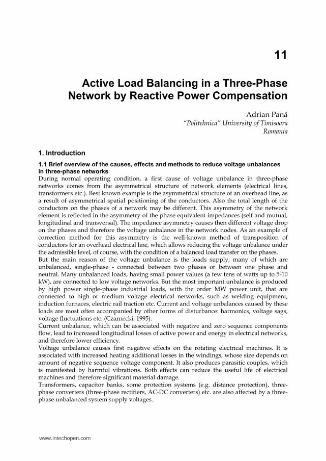
As is known, Steinmetz showed that the voltage unbalance caused by unbalanced currents
produced in a three-phase network by connecting a resistive load (with the equivalent
conductance G) between two phases, can be eliminated by installing two reactive loads, an
inductance (a coil, having equivalent susceptance / 3LB G= ) and a capacitance (a capacitor
with equivalent susceptance / 3CB G= − ). The ensemble of the three receivers, forming a
delta connection (Δ), can be equalized to a perfectly balanced three-phase loads, in star
connection (Y), having on each branch an equivalent admittance purely resistive
(conductance) with the value G (Fig. 1).
a) b)
Fig. 1. Steinmetz montage and its equivalence with a load balanced, purely resistive
www.intechopen.com

Active Load Balancing in a Three-Phase Network by Reactive Power Compensation
221
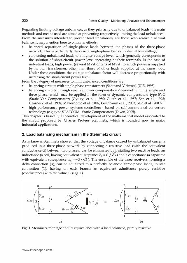
To explain how to achieve balancing by reactive power compensation of a three-phase network supplying a resistive load, it will consider successively the three receivers, supplied individually. For each receiver will determine the phase currents, which are then decomposed by reference to the corresponding phase to neutral voltages, to find active and reactive components of currents, which are used then to determine the active and reactive powers flow on the phases of the network. It is assumed that the phase-to-neutral voltages and phase-to-phase voltages at source forms perfectly symmetrical three-phase sets. Also conductor’s impedances are neglected. Therefore, for the case of supplying the resistive load having equivalent conductance G between R and S phases (Fig. 2.), a current in phase with the applied voltage is formed on the R phase conductor:
a)
b)
Fig. 2. Resistive load supplied between R and S phases
RS RSI U G= ⋅ (1)
The equation to calculate the rms value is:
3RSI U G= ⋅ ⋅ , (2)
where U is the rms value of phase-to-neutral voltage, considered the same on the three phases. On the S phase conductor, an equal but opposite current like the one on the R phase is formed:
SR RSI I= − (3)
The two currents are now reported each to the corresponding phase-to-neutral voltage, in
order to find the active respectively reactive components of each other. For this, the complex
plane is associated to the phase-to-neutral voltage; its phasor is positioned in the real axis,
www.intechopen.com
Power Quality – Monitoring, Analysis and Enhancement
222
positive direction. It is noted that the current phasor on the phase R, ( )R R RSI I= , is leading
the corresponding phase-to-neutral voltage phasor, RU , with an phase-shift equal to /6π
rad, which means that the reactive component has capacitive character:
( ) 1( ) 1( ) 1( ) 1( )
3 3cos sin
6 6 2 2R R R R a R R r R R R RI I jI I jI U G j U G
π π= + = ⋅ + ⋅ = ⋅ ⋅ + ⋅ ⋅ (4)
It can now deduce the equations for the active and reactive power flow on R phase:
* 2 2
1( )1 1 1
3 3
2 2R RR R R RS P jQ U I U G j U G= + = ⋅ = ⋅ ⋅ − ⋅ ⋅ (5)
On the S phase, the current phasor is lagging the voltage SU with a phase-shift equal to
/6π rad, which means that the reactive component has inductive character. By a similar
calculation with the above, active and reactive powers flow on the S phase are obtained:
* 2 2
1( )1 1 1
3 3
2 2S SS S S SS P jQ U I U G j U G= + = ⋅ = ⋅ ⋅ + ⋅ ⋅ (6)
It may be noted that the resistive load supplied between two phases, absorbs active power equal on the two phases. But it occurs also on the reactive power flow on the network phases, absorbing reactive power on the S phase, but returning it to the source on the R phase, without modifying the reactive power flow on all three phases. On this ensemble, result:
2 21 1 1 3 ( 3 )R SP P P U G U G= + = ⋅ ⋅ = ⋅ ⋅ şi 1 1 1 0R SQ Q Q= + = (7)
A similar demonstration can be done for supplying the capacitive load having the
equivalent susceptance / 3CB G= − , between phases S and T (Fig. 3).
The current formed on the S phase conductor is leading the voltage with a phase-shift equal
to /2π rad (the complex plane associated to the phase-to-phase voltage STU ):
ST ST CI j U B= ⋅ ⋅ (8)
The rms value can be determined by the equation:
3ST CI U B U G= ⋅ ⋅ = ⋅ (9)
The current formed on the T phase, have the same rms value and is opposite to that on the S phase:
TS STI I= − (10)
Now reporting the two currents to the corresponding phase-to-neutral voltages, it can be determined the active and reactive components of this, and then the active and reactive powers on the two phases:
* 2 2
2( )2 2 2
1 3
2 2S SS S S SS P jQ U I U G j U G= + = ⋅ = − ⋅ ⋅ − ⋅ ⋅ (11)
www.intechopen.com

Active Load Balancing in a Three-Phase Network by Reactive Power Compensation
223
* 2 2
2( )2 2 2
1 3
2 2T ST T T TS P jQ U I U G j U G= + = ⋅ = ⋅ ⋅ − ⋅ ⋅ (12)
It is noted that the capacitive load absorbs the same reactive power on the two phases at which it is connected. It occurs also on the active powers flow, absorbs active power on phase T, but returns it to the source on the phase S. On all three phases of the network, results:
2 2 2 0S TP P P= + = şi 2 22 2 2 ( 3 ) 3S T CQ Q Q U B U G= + = − ⋅ ⋅ = − ⋅ ⋅ (13)
a)
b)
Fig. 3. The capacitive load supplied between phases S and T
The same method applies now to the case of inductive load, having equivalent susceptance
/ 3LB G= supplied between T and R phases (Fig. 4).
The current formed on the T phase conductor is lagging the supplying voltage with an
phase-shift equal to /2π rad:
TR TR LI j U B= − ⋅ ⋅ (14)
The rms value can be determined using the equation:
3TR LI U B U G= ⋅ ⋅ = ⋅ (15)
The current formed on the R phase, have the same rms value and is opposite to that on the T phase:
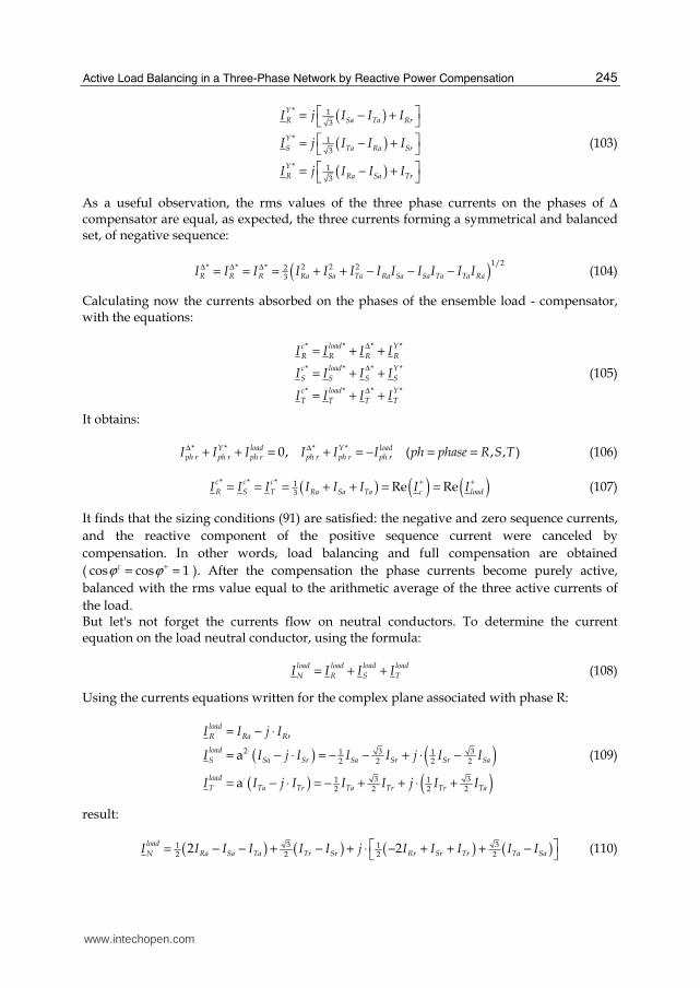
RT TRI I= − (16)
www.intechopen.com

Power Quality – Monitoring, Analysis and Enhancement
224
a)
b)
Fig. 4. Inductive load supplied between T and R phases
Now reporting the two currents to the corresponding phase-to-neutral voltages, it can be determined the active and reactive components of this, and then the active and reactive powers on the two phases:
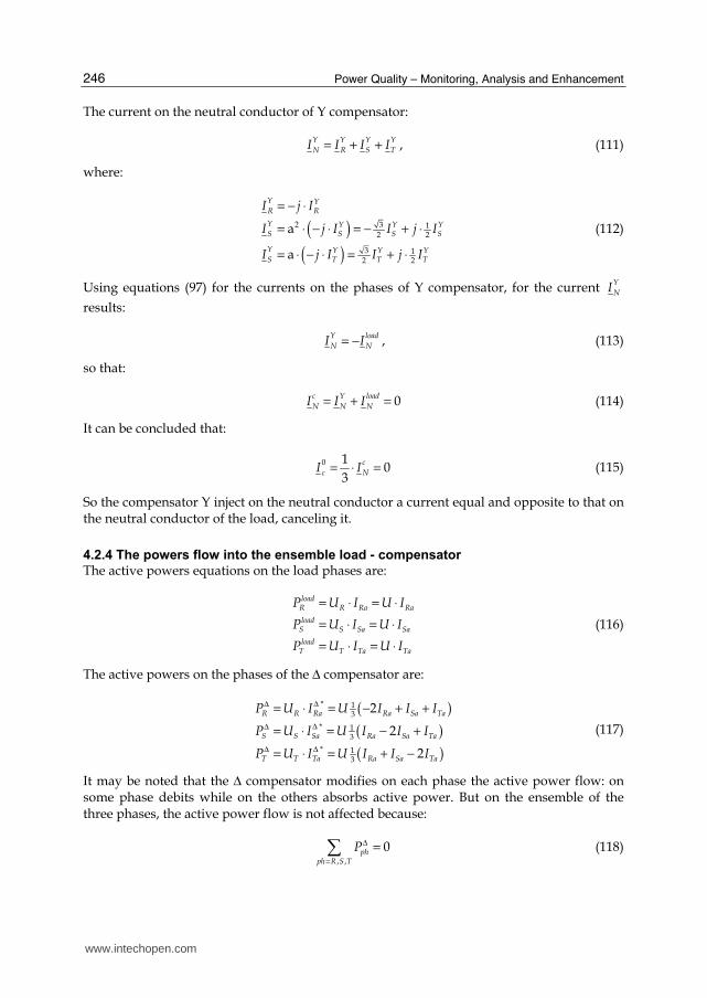
* 2 2
3( )3 3 3
1 3
2 2T TT T T TS P jQ U I U G j U G= + = ⋅ = ⋅ ⋅ + ⋅ ⋅ (17)
* 2 2
3( )3 3 3
1 3
2 2R RS S S TS P jQ U I U G j U G= + = ⋅ = − ⋅ ⋅ + ⋅ ⋅ (18)
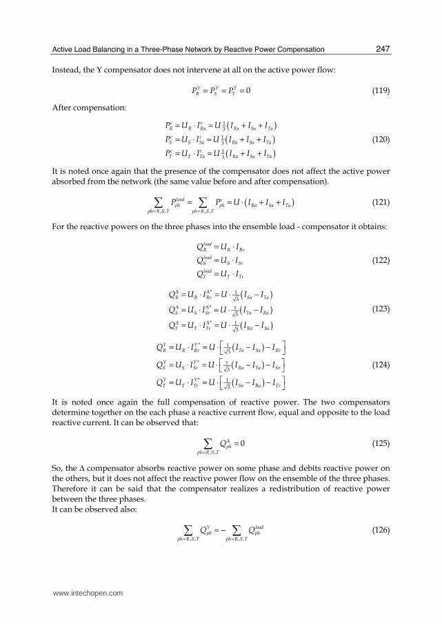
It is noted that the inductive load absorbs the same reactive power on the two phases at which it is connected. It occurs also on the active powers flow, absorbs active power on phase T, but returns it to the source on the phase R. On all three phases of the network, results:
3 3 3 0T RP P P= + = and 2 23 3 3 ( 3 ) 3T R LQ Q Q U B U G= + = ⋅ ⋅ = ⋅ ⋅ (19)
To deduce the power flow on the network phases that supply simultaneously the three loads previously considered, we can apply the superposition theorem (Fig. 5). Active and reactive powers flow run on the network phases that supply the ensemble of all three loads are obtained by algebraic addition of active and reactive power previously deducted for the individual supplying circuits. It obtains:
21 3R R RP P P U G= + = ⋅ , 1 3 0R R RQ Q Q= + = (20)
21 2S S SP P P U G= + = ⋅ 1 2 0S S SQ Q Q= + = (21)
22 3T T TP P P U G= + = ⋅ 2 3 0T T TQ Q Q= + = (22)
www.intechopen.com

Active Load Balancing in a Three-Phase Network by Reactive Power Compensation
225
23R S TP P P P U G= + + = ⋅ ⋅ 0R S TQ Q Q Q= + + = (23)
a)
b)
Fig. 5. The ensemble of the three loads
It notes that after the compensation, in the supplying network of the ensemble of the three receivers, only active power flows, the same on the three phases. The compensation
conduces to maximize the power factor ( 0Q = ) and to active load balancing on the three
phases:
23 3phaseP P U G= ⋅ = ⋅ ⋅ (24)
The ensemble of the three loads, in Δ connection can be equated with three equal active loads, single-phase, each having equivalent conductance with value G, in Y connection (Fig. 1). The three currents have the same phase-shift with the corresponding phase-to-neutral voltages and have the same rms value (Fig. 5):
R S TI I I U G= = = ⋅ (25)
3. Most common applications of Steinmetz circuit
Steinmetz circuit is usually applied to balance large loads, with values of order MW of power, whose contribution to the voltage unbalance in the connecting node is very high. Figure 6.a presents simplified supply circuit diagram of a three-phase network, of a single-phase induction furnace. Furnace coil is connected secondary of the single-phase transformer T. Its primary is connected between two phases of a medium voltage network. Capacitance C1 connected in parallel with the load, is to compensate its reactive component and therefore to improve the power factor. Capacitance C2 and inductance L2 are sized to achieve load balancing active component, as shown above. But the active power of the load is variable, depending on the specific technological process. To ensure adaptive single-phase load balancing, capacitor banks having the capacitances C1 and C2 and inductance L2 have to allow the control of these values according to load variation.
www.intechopen.com

Power Quality – Monitoring, Analysis and Enhancement
226
a)
b)
Fig. 6. Simplified circuit of Steinmetz installation for load-balancing applications in the case: a) induction furnace; b) railway electric traction
Another important application of the Steinmetz circuit is load balancing in three-phase networks which supplies electric traction railway, equivalent to a single-phase load. Figure 6.b shows the simplified circuit diagram of a substation supply of section from an electric railway line. Since the load is changing rapidly and within large limits, the compensator elements must satisfy the same requirements. Is needed a dynamic load balancing (Grünbaum et al., 2003). The solution applied use a SVC (Static Var Compensator) realized by a TCR (Thyristor Controlled Reactor). Controlling the thyristors (connected back-to-back) which are in series with the inductances L1, L2 and L3 allow a dynamic control of inductive and capacitive currents on the branches of the compensator. Thus is performed a dynamic compensation of reactive load (increasing the power factor) and dynamic balancing of active load in the supply network. Application of the Steinmetz circuit is a simple solution, relatively inexpensive and efficient, which can be applied to any voltage level at any value of load power, a perfect load balancing on the three phases is obtained. However, it presents the following inconveniences: - the frequency of 50 Hz, the ensemble load - compensator can be equated with
impedance perfectly balanced, but on other frequencies, namely the higher harmonics that can be generated by the same load or close loads, it causes a strong unbalance;
- dimensioning the compensator should be made taking into account the restriction to avoid parallel resonance between the equivalent capacitance of the compensator and the network equivalent inductance seen at the point of connection to the network, for harmonic frequencies present in the steady operation conditions, the capacitors will be included in passive filters for harmonic currents.
4. The generalized Steinmetz circuit
The circuit available for a single phase active load connected between two phases can be extended to a certain unbalanced three-phase load with active and reactive components (inductive and / or capacitive). The mathematical model for sizing the compensator elements and determining the currents flow and powers flow for the purpose of understanding the compensation mechanism and for conception of control algorithms
www.intechopen.com
Active Load Balancing in a Three-Phase Network by Reactive Power Compensation
227
depend on the presence or not of neutral conductor and so of the presence or not of zero sequence components of currents. In the following, the two situations are analyzed.
4.1 The generalized Steinmetz circuit for three-phase three-wire networks
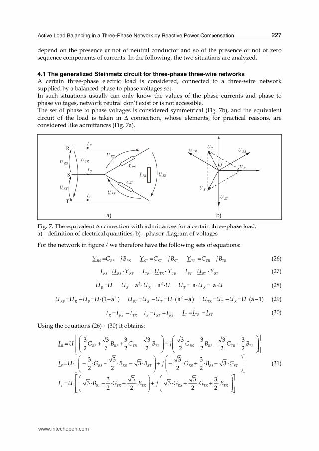
A certain three-phase electric load is considered, connected to a three-wire network supplied by a balanced phase to phase voltages set. In such situations usually can only know the values of the phase currents and phase to phase voltages, network neutral don’t exist or is not accessible. The set of phase to phase voltages is considered symmetrical (Fig. 7b), and the equivalent
circuit of the load is taken in Δ connection, whose elements, for practical reasons, are considered like admittances (Fig. 7a).
a) b)
Fig. 7. The equivalent Δ connection with admittances for a certain three-phase load: a) - definition of electrical quantities, b) - phasor diagram of voltages
For the network in figure 7 we therefore have the following sets of equations:
RS RSRSY G j B= − ST STSTY G j B= − TR TRTRY G j B= − (26)
RS RSRSI U Y= ⋅ TR TRTRI U Y= ⋅ ST STSTI U Y= ⋅ (27)
RU U= 2 2a aS RU U U= ⋅ = ⋅ a aT RU U U= ⋅ = ⋅ (28)
2(1 a )RS R SU U U U= − = ⋅ − 2(a a )ST S TU U U U= − = ⋅ − (a 1)TR T RU U U U= − = ⋅ − (29)
R RS TRI I I= − S ST RSI I I= − T TR STI I I= − (30)
Using the equations (26) ÷ (30) it obtains:
3 3 3 3 3 3 3 3
2 2 2 2 2 2 2 2
3 3 3 33 3
2 2 2 2
3 3 3 33 3
2 2 2 2
RS RS TR TR RS RS TR TRR
RS RS ST RS RS STS
ST TR TR RS TR TRT
I U G B G B j G B G B
I U G B B j G B G
I U B G B j G G B
= + + − + − − − = ⋅ − ⋅ − ⋅ − ⋅ + − ⋅ + ⋅ − ⋅
= ⋅ ⋅ − ⋅ + ⋅ + ⋅ + ⋅ + ⋅
(31)
www.intechopen.com

Power Quality – Monitoring, Analysis and Enhancement
228
Necessary and sufficient condition for the three phase currents to form a balanced set is the cancellation of the negative sequence current component:
( )21a a 0
3Si R TI I I I= ⋅ + ⋅ + ⋅ = (32)
Putting the cancellation conditions for the real and imaginary parts of Ii obtained by substituting equations (31) in (32) we obtain the conditions:
( )
( )
2 3 0
3 2 0
RS ST TR TR RS
TR RS RS ST TR
G G G B B
G G B B B
− + ⋅ − + ⋅ − =⋅ − + − ⋅ + = (33)
This system of equations define the relationship that should exist between the six elements
of the equivalent Δ connection of a load, so that, from the point of view of the network it appear as a perfectly balanced load (Ii = 0). These conditions can be obtained by changing (compensating) the equivalent parameters
using a parallel compensation circuit, also in Δ connection, so that equations (33) (Gyugyi et al., 1980) to be satisfied for the ensemble load - compensator (Fig. 8).
Fig. 8. The ensemble unbalanced load - shunt compensator
The problem lies in determining the elements of the compensator, so that, knowing the elements of the equivalent circuit of the load, to obtain an ensemble which is perfectly balanced from the point of view of the network, as it means that after the compensation, the currents on the phases satisfy the condition:
= ⋅ = ⋅2a ac c c
R S TI I I (34)
The compensator will not produce changes in the total active power absorbed from the
network (which would mean further losses) and hence will contain only reactive elements
( 0RS ST TRG G GΔ Δ Δ= = = ). In equations (33) will be replaced so:
www.intechopen.com
Active Load Balancing in a Three-Phase Network by Reactive Power Compensation
229
( ) ( ) ( )
;
; ;
load load loadRS RS ST ST TR TR
load load loadRS RS RS ST ST ST TR TR TR
G G G G G G
B B B B B B B B BΔ Δ Δ
= = =
= + = + = + (35)
From the equations (33) resulting the equation system:
2
RS TR
RS ST TR
B B A
B B B B
Δ Δ
Δ Δ Δ
− =− ⋅ + = (36)
Where:
1 2 1
3 3 3
3 2 3
load load load load loadRS RS ST TR TR
load load load load loadRS RS ST TR TR
A G B G G B
B G B B G B
= − ⋅ − + ⋅ − ⋅ +
= ⋅ − + ⋅ − ⋅ −
(37)
Unknowns are therefore: RSB Δ , STB Δ and TRB Δ . With two equations and three unknowns, we are dealing with indeterminacy. A third equation, independent of the first two, which expresses a relationship between the three unknowns, will result by imposing any of the following conditions: a. full compensation of reactive power demand from network; b. partial compensation of reactive power demand (up to a required level of power factor); c. voltage control on the load bus bars trough the control of reactive power demand; d. install a minimum reactive power for the compensator; e. minimize active power losses in the supply network of the load. In this chapter we will consider only the operation of the compensator sized according to the a criterion, other criteria can be treated similarly.
4.1.1 Sizing the compensator elements based on the criterion of total compensation of reactive power demand from the network
According to a criterion, in addition to load balancing, compensation should also lead to
cancellation of the reactive power absorbed from the network on the positive sequence
( cos 1ϕ + = ). This is equivalent to the additional condition:
( )Im 0cI+
= (38)
cI+
is the positive sequence component corresponding to the load current of the ensemble
load - compensator. But for this it can write the condition:
( )21a a
3
c c c c
c R S T RI I I I I+
= ⋅ + ⋅ + ⋅ = , (39)
because 2a ac c c
R S TI I I= ⋅ = ⋅ , where c
RI , c
SI and c
TI are the currents absorbed by the network
after the compensation. As the supplementary condition will be:
( )Im 0c
RI = (40)
mean: ( )3 0RS TR RS TRG G B B− − + = (41)
www.intechopen.com

Power Quality – Monitoring, Analysis and Enhancement
230
Associating now the equations (33) and (41), where the equations (35) are replaced, the system of three equations with three unknowns is obtained:
1 0 1
1 2 1
1 0 1
RS
ST
TR
B A
B B
B C
Δ
Δ
Δ
− − ⋅ =
(42)
where: ( )1
3 33
load load load loadRS RS TR TRC G B G B= ⋅ − ⋅ − − ⋅ (43)
Solving the system (42) leads to the following solutions:
( )
( )
( )
Δ
Δ
Δ
= ⋅ +
= ⋅ +
= ⋅ − +
1
21
21
2
RS
ST
TR
B A C
B B C
B A C
(44)
mean:
( )
( )
( )
1
3
1
3
1
3
load load loadRS RS ST TR
load load loadST ST TR RS
load load loadTR TR RS ST
B B G G
B B G G
B B G G
Δ
Δ
Δ
=− + −= − + −=− + −
(45)
Using now the equations of transformation of a delta connection circuit in a equivalent Y connection circuit, is achieved:
0
load load loadR S T RS ST TR
R S T
G G G G G G G
B B B
= = = + + =
= = = (46)
These equivalences are illustrated in Figure 9.
Fig. 9. Equivalence of the ensemble load – compensator with a balanced active load
www.intechopen.com

Active Load Balancing in a Three-Phase Network by Reactive Power Compensation
231
4.1.2 The compensation circuit elements expressed by using the sequence components of the load currents
Expressing the compensation circuit elements by using the sequence components of the load currents will allow a full interpretation of the mechanism of compensation. For this, lets’ consider again the general three-phase unbalanced load, supplied from a
balanced three-phase source, without neutral, represented by the equivalent Δ circuit as shown in Fig. 7. The three absorbed load currents will be:
2
2 2
2
(1 a ) (a 1)
(a a) (1 a )
(a 1) (a a)
load load load
R RS TR
load load load
S ST RS
load load load
T TR ST
I U Y Y
I U Y Y
I U Y Y
= ⋅ ⋅ − − ⋅ − = ⋅ ⋅ − − ⋅ − = ⋅ ⋅ − − ⋅ −
(47)
We apply the known equations for the sequence components:
2
2
0
1( a a )
31
( a a )31
( )3
load load load
load R S T
load load load
load R S T
load load load
load R S T
I I I I
I I I I
I I I I
+
−
= ⋅ + ⋅ + ⋅
= ⋅ + ⋅ + ⋅
= ⋅ + +
(48)
where loadI+
, loadI−
and 0
loadI are the positive, negative and zero sequence components
(corresponding to the reference phase, R). Replacing the equations (47) in equations (48) the
symmetrical components depending on the load admittances are obtained:
2
0
( )
(a a )
0
load load load
load RS ST TR
load load load
load RS ST TR
load
I U Y Y Y
I U Y Y Y
I
+
−
= ⋅ + +
= − ⋅ ⋅ + + ⋅
=
(49)
Symmetrical components of currents on the compensator phases are obtained by the same way:
( )
( ) ( ) ( )2
0
3 1a a 2
2 2
0
RS ST TR
RS ST TR TR RS RS ST TR
I j B B B U
I j B B B U U B B j U B B B
I
+ ΔΔ Δ
Δ
− Δ Δ Δ Δ Δ Δ Δ Δ
Δ
Δ
= − + + ⋅
= ⋅ + + ⋅ ⋅ = ⋅ ⋅ − + ⋅ ⋅ ⋅ − ⋅ +
=
(50)
Writing symmetrical components of the phase currents absorbed from the network by the ensemble load - compensator:
0
0
c load
c load
c
I I I
I I I
I
+ + +
Δ
− − −
Δ
= +
= +
=
(51)
www.intechopen.com

Power Quality – Monitoring, Analysis and Enhancement
232
The sizing conditions receive the form:
Im( ) 0
Re( ) 0
Im( ) 0
c
c
c
I
I
I
+
−
−
===
( )
( )
( )
Im( ) 0
3Re( ) 0
21
Im( ) 2 02
RS ST TRload
TR RSload
RS ST TRload
I U B B B
I U B B
I U B B B
+ Δ Δ Δ
− Δ Δ
− Δ Δ Δ
− ⋅ + + =− ⋅ − =− ⋅ − + =
(52)
Solving this system of equations give the following solutions:
1 1 1Im( ) Re( ) Im( )
3 3 3
1 1 2Im( ) Re( )
3 3 3
1 1 1Im( ) Re( ) Im( )
3 3 3
RS load load load
ST load load
TR load load load
B I I IU
B I IU
B I I IU
+ − −Δ
+ −Δ
+ − −Δ
= − ⋅ − ⋅ + − ⋅
⋅
= − ⋅ − ⋅ + ⋅ ⋅
= − ⋅ − ⋅ − − ⋅
⋅
(53)
Since the positive sequence and negative sequence currents flow can be considered
independent, Δ compensator also can be decomposed into two independent Δ
compensators, fictitious or real. Therefore one compensator will be symmetrical (Δ+) and
produce compensation (cancellation) of the reactive component of the positive sequence
load currents and the other will be unbalanced (Δ-), and will compensate the negative
sequence load current. The mechanism of the compensation of the sequence load currents components is illustrated in Figure 10.
Fig. 10. Compensator representation by two independent compensators: one for the positive sequence compensation and other for the negative sequence compensation of the load current
www.intechopen.com

Active Load Balancing in a Three-Phase Network by Reactive Power Compensation
233
The elements of the two compensators will be:
1Im( )
3
1 1Re( ) Im( )
33
2Im( )
3
1 1Re( ) Im( )
33
RS ST TR load
RS load load
ST load
TR load load
B B B IU
B I IUU
B IU
B I IUU
+Δ + Δ + Δ +
− −Δ −
−Δ−
− −Δ −
= = = ⋅⋅
= − ⋅ + ⋅⋅⋅
= − ⋅⋅
= ⋅ + ⋅⋅⋅
(54)
Expressing then real and imaginary parts of symmetrical components depending on the elements of the equivalent circuit of the load, i.e.:
( )Im( )
1 3 1 3Re( )
2 2 2 2
3 1 3 1Im( ) ,
2 2 2 2
load load loadRS ST TRload
load load load load loadRS RS ST TR TRload
load load load load loadRS RS ST TR TRload
I B B B U
I G B G G B U
I G B B G B U
+
−
−
= − + + ⋅
= ⋅ + − + ⋅ − ⋅ ⋅
= ⋅ − + − ⋅ − ⋅ ⋅
(55)
it obtain:
1( )
3
2 1 1 1( )
3 3 3 3
1 2 1 1( )
3 3 3 3
1 1 2
3 3 3
load load loadRS ST TR RS ST TR
load load load load loadRS RS ST TR TR ST
load load load load loadST RS ST TR RS TR
load loadTR RS ST T
B B B B B B
B B B B G G
B B B B G G
B B B B
Δ + Δ + Δ+
Δ −
Δ −
Δ −
= = = − ⋅ + +
= ⋅ − ⋅ − ⋅ + ⋅ −
= − ⋅ + ⋅ − ⋅ + ⋅ −
= − ⋅ − ⋅ + ⋅1
( )3
load load loadR ST RSG G+ ⋅ −
(56)
It is noted that the sum of Δ- compensator elements values is zero.
0RS ST TRB B BΔ − Δ − Δ −+ + = (57)
Instead, the sum of the Δ+ compensator elements will be equal and opposite to the sum of
the reactive elements of the load.
4.1.3 Currents flow in the ensemble load - compensator expressed by symmetrical components
On the basis of equations (53), the currents on the branches of the two Δ+ and Δ- fictitious
compensators can be determined, using real and imaginary parts of the sequence currents of load:
www.intechopen.com

Power Quality – Monitoring, Analysis and Enhancement
234
( )
( ) ( )
( )
( ) ( )
1Im
3
1Re Im
3
2Im
3
1Re Im
3
RS ST TR load
RS load load
ST load
TR load load
I I I I
I I I
I I
I I I
+Δ+ Δ+ Δ+
− −Δ−
−Δ−
− −Δ−
= = = ⋅
= − + ⋅
= − ⋅
= + ⋅
(58)
With these equations we can determine the currents on the phases of both fictitious compensators, and then the currents flow in symmetrical components, into the ensemble load - compensator.
( )
( )
( )
, , , , ,
, , , ,
, , , ,
1 3 3
2 2 2
1 32
2 2
1 32
2 2
R RS TR RS TR
S RS ST RS
T TR ST TR
I I I j I I
I I I j I
I I I j I
Δ+ − Δ+ − Δ+ − Δ+ − Δ+ −
Δ+ − Δ+ − Δ+ − Δ+ −
Δ+ − Δ+ − Δ+ − Δ+ −
= ⋅ − + − ⋅ − ⋅ = − ⋅ + ⋅ + ⋅
= ⋅ + ⋅ + ⋅
(59)
Δ+ compensator produces a three-phase set of positive sequence currents, which compensate the reactive component of the positive sequence load current on each phase,
and Δ- compensator produces a three-phase set of negative sequence currents, which compensate the negative sequence load current on each phase (both active and reactive component):
( )ImR loadI j IΔ+ +
= − ( )2a ImS loadI j IΔ+ + = ⋅ − ( )a ImT loadI j I
Δ+ + = ⋅ − (60)
R loadI IΔ− −
= − a ( )S loadI IΔ− −
= ⋅ − 2a ( )T loadI IΔ− −
= ⋅ − (61)
The currents on the three phases, after compensation, represent a balanced set, positive sequence and contain only the active component (they have zero phase-shift relative to the corresponding phase-to-neutral voltage), equal to the active component of positive sequence load current:
( )
( )
( )
2
Re
a Re
a Re
c load
R R R R load
c load
S S S S load
c load
T T T T load
I I I I I
I I I I I
I I I I I
Δ+ Δ− +
Δ+ Δ− +
Δ+ Δ− +
= + + =
= + + = ⋅
= + + = ⋅
(62)
Figure 11 shows the compensation mechanism of load currents symmetrical components using phasor diagram.
Starting from the three phasors of unbalanced load currents, considered arbitrary, but check
the condition 0R S TI I I+ + = (which means they have a common origin in the center of
gravity of the triangle formed by the peaks of the phasors), were determined the reference
www.intechopen.com
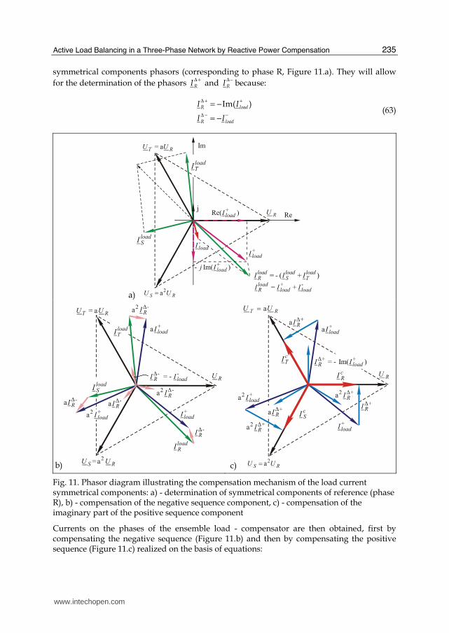
Active Load Balancing in a Three-Phase Network by Reactive Power Compensation
235
symmetrical components phasors (corresponding to phase R, Figure 11.a). They will allow
for the determination of the phasors RIΔ +
and RIΔ−
because:
Im( )R load
R load
I I
I I
Δ + +
Δ − −
= −
= − (63)
a)
b) c)
Fig. 11. Phasor diagram illustrating the compensation mechanism of the load current symmetrical components: a) - determination of symmetrical components of reference (phase R), b) - compensation of the negative sequence component, c) - compensation of the imaginary part of the positive sequence component
Currents on the phases of the ensemble load - compensator are then obtained, first by compensating the negative sequence (Figure 11.b) and then by compensating the positive sequence (Figure 11.c) realized on the basis of equations:
www.intechopen.com

Power Quality – Monitoring, Analysis and Enhancement
236
2
2
c s d i
R R R R
c s d i
S S R R
c s d i
T T R R
I I I I
I I a I a I
I I a I a I
Δ Δ
Δ Δ
Δ Δ
= + +
= + ⋅ + ⋅
= + ⋅ + ⋅
(64)
Obviously that in practical applications is not economically to use two compensators. A
single compensator, having variables susceptances will be sufficient to produce both
positive sequence compensation (increasing power factor) and the negative sequence load
currents compensation (load balancing).
4.1.4 Currents and compensation circuit elements expressed by load currents
Using the currents equations on the load phases with active and reactive components and
supposing their inductive character, mean:
2a ( )
a ( ),
load
Ra RrR
load
Sa SrS
load
Ta TrT
I I jI
I I jI
I I jI
= −
= ⋅ −
= ⋅ −
(65)
and replacing into the sequence currents equations (48) results:
1 1( ) ( )
3 3
1 1 3 1 3 1 1 3 1 3
3 2 2 2 2 3 2 2 2 2
Ra Sa Ta Rr Sr Trload
Ra Sa Sr Ta Tr Rr Sr Sa Tr Taload
I I I I j I I I
I I I I I I j I I I I I
+
−
= ⋅ + + − ⋅ + +
= ⋅ − ⋅ + ⋅ − ⋅ − ⋅ + ⋅ − + ⋅ + ⋅ + ⋅ − ⋅
(66)
By developing the equations (58), we obtain relations between currents respectively
susceptances on the compensator branches respectively active and reactive components of
currents on the load phases:
1 1( ) (2 2 )
3 3 3
1 1( ) ( 2 2 )
3 3 3
1 1( ) (2 2 )
3 3 3
Sa Ra Rr Sr TrRS
Ta Sa Rr Sr TrST
Ra Ta Rr Sr TrTR
I I I I I I
I I I I I I
I I I I I I
Δ
Δ
Δ
= ⋅ − − ⋅ ⋅ + ⋅ −
= ⋅ − − ⋅ − + ⋅ + ⋅
= ⋅ − − ⋅ ⋅ − + ⋅
(67)
1 1( ) ( 2 2 )
3 3 3
1 1( ) ( 2 2 )
3 3 3
1 1( ) ( 2 2 )
3 3 3
RS Sa Ra Tr Rr Sr
ST Ta Sa Rr Sr Tr
TR Ra Ta Sr Rr Tr
B I I I I IU
B I I I I IU
B I I I I IU
Δ
Δ
Δ
= ⋅ − + ⋅ − ⋅ − ⋅
⋅
= ⋅ − + ⋅ − ⋅ − ⋅ ⋅
= ⋅ − + ⋅ − ⋅ − ⋅
⋅
(68)
www.intechopen.com

Active Load Balancing in a Three-Phase Network by Reactive Power Compensation
237
And for the fictitious Δ+ and Δ- compensators, taking into account the equations (58), are
obtained:
1( )
3 3
1 1( ) ( 2 )
3 3 3
1 1( ) (2 )
3 3 3
1 1( ) ( 2 )
3 3 3
RS ST TR Rr Sr Tr
RS Ra Sa Rr Sr Tr
ST Sa Ta Rr Sr Tr
TR Ta Ra Rr Sr Tr
I I I I I I
I I I I I I
I I I I I I
I I I I I I
Δ+ Δ+ Δ+
Δ−
Δ−
Δ−
= = = − ⋅ + +
= ⋅ − + + ⋅ − − + ⋅
= ⋅ − + + ⋅ ⋅ − −
= ⋅ − + + ⋅ − + ⋅ −
(69)
1( )
9
1 1( 2 )
3 3 3
1 1(2 )
3 3 3
1 1( 2 )
3 3 3
RS ST TR Rr Sr Tr
RS Ra Sa Rr Sr Tr
ST Sa Ta Rr Sr Tr
TR Ta Ra Rr Sr Tr
B B B I I IU
B I I I I IU
B I I I I IU
B I I I I IU
Δ+ Δ+ Δ+
Δ−
Δ−
Δ−
= = = − ⋅ + +⋅
= − + + − − +
= − + + − −
= − + + − + −
(70)
4.1.5 The currents and powers flow into the ensemble load-compensator expressed in phase components
Analytical determination of the currents and powers flow into the ensemble load -
compensator is useful for performing calculations for sizing or for checking the accuracy of
compensation in real installations.
Using equations (59), written to the complex plane associated with phase R, is determined
the current equations ,
SIΔ+ −
, respectively ,
TIΔ+ −
written in complex plans associated to corres-
ding phase-to-neutral voltages (noted ,
SIΔ+ −∗
respectively,
TIΔ+ −∗
), making the operations:
, ,
aS SI IΔ+ −∗ Δ+ −
= ⋅ , ,2aT TI I
Δ+ −∗ Δ+ −= ⋅ (71)
Result:
, , , , ,
, , , , ,
, , , , ,
1 3( ) ( )
2 2
1 3( ) ( )
2 2
1 3( ) ( )
2 2
RS TR RS TRR
ST RS RS STS
TR ST TR STT
I I I j I I
I I I j I I
I I I j I I
Δ+ −∗ Δ+ − Δ+ − Δ+ − Δ+ −
Δ+ −∗ Δ+ − Δ+ − Δ+ − Δ+ −
Δ+ −∗ Δ+ − Δ+ − Δ+ − + −
= ⋅ − − ⋅ +
= ⋅ − − ⋅ +
= ⋅ − − ⋅ +
(72)
Combining now the equations (69) with (72) the equations for the currents on the Δ+ and Δ-
phases, relatively to the corresponding phase-to-neutral voltages are obtained:
www.intechopen.com

Power Quality – Monitoring, Analysis and Enhancement
238
[ ]
[ ]
[ ]
1( )
3
12 (2 )
3
12 (2 )
3
12 (2 )
3
Rr Sr TrR S T
Ra Sa Ta Rr Sr TrR
Sa Ta Ra Sr Tr RrS
Ta Ra Sa Tr Rr SrT
I I I j I I I
I I I I j I I I
I I I I j I I I
I I I I j I I I
Δ+∗ Δ+∗ Δ+∗
Δ−∗
Δ−∗
Δ−∗
= = = ⋅ + +
= ⋅ − ⋅ + + + ⋅ − −
= ⋅ − ⋅ + + + ⋅ − −
= ⋅ − ⋅ + + + ⋅ − −
(73)
Using now the equations (69), (72), and (73), for the currents on the compensator phases are obtained the equations:
1( 2 )
31
( 2 )31
( 2 )3
Ra Sa Ta RrR R R
Ra Sa Ta SrS S S
Ra Sa Ta TrT T T
I I I I I I jI
I I I I I I jI
I I I I I I jI
Δ∗ Δ+∗ Δ−∗
Δ∗ Δ+∗ Δ−∗
Δ∗ Δ+∗ Δ−∗
= + = ⋅ − ⋅ + + +
= + = ⋅ − ⋅ + +
= + = ⋅ + − ⋅ +
(74)
It can be seen clear that the compensator provides on each phase a reactive current component which is equal and opposite to the reactive component of load current. As the active components of the compensating currents, it is positive or negative, being equal to the difference between the active component of positive sequence current (which is the network load on each phase after compensation) and the active component of load each current. Can be now calculated the currents absorbed on each phase by the ensemble load - compensator:
c load
R R R R
c load
S S S S
c load
T T T T
I I I I
I I I I
I I I I
∗ ∗ Δ+∗ Δ−∗
∗ ∗ Δ+∗ Δ−∗
∗ ∗ Δ+∗ Δ−∗
= + +
= + +
= + +
(75)
It’s obtained:
( ) ( )1
Re3
c c c
Ra Sa TaR S T loadI I I I I I I∗ ∗ ∗ +
= = = ⋅ + + = (76)
The active and reactive powers on the three phases of the compensator can now be easily calculated:
1 12 3 ( ) ( 2 )
6 31 1
2 3 ( ) ( 2 )6 31 1
2 3 ( ) (6 3
R R Ra Ra Sa Ta Tr Sr Ra Sa Ta
S S Sa Ra Sa Ta Rr Tr Ra Sa Ta
T T Ta Ra Sa Ta Sr Rr Ra Sa
P U I U I I I I I U I I I
P U I U I I I I I U I I I
P U I U I I I I I U I I
Δ Δ∗
Δ Δ∗
Δ Δ∗
= ⋅ = ⋅ ⋅ − ⋅ + + + ⋅ − = ⋅ ⋅ − ⋅ + + = ⋅ = ⋅ ⋅ − ⋅ + + ⋅ − = ⋅ ⋅ − ⋅ + = ⋅ = ⋅ ⋅ + − ⋅ + ⋅ − = ⋅ ⋅ + − 2 )TaI⋅
(77)
www.intechopen.com
Active Load Balancing in a Three-Phase Network by Reactive Power Compensation
239
0
, ,
R S T
R R S S T T
P P P
P P P P P P
Δ+ Δ+ Δ+
Δ− Δ Δ− Δ Δ− Δ
= = =
= = = (78)
So, the positive sequence compensator intervenes only on the reactive power flow, and the negative sequence compensator, although it change the active power on each phase of the compensated network, on the ensemble of the three phases don’t change the active power balance because:
0R S TP P PΔ− Δ− Δ−+ + = (79)
This means that on some phase(s) the Δ- compensator absorbs active power, and on the other(s) debits active power as otherwise noted above. He thus produces a redistribution of active power between the phases, balancing them. It can be said that it made active power compensation. After compensation:
1
( )3
c c cR S T Ra Sa TaP P P U I I I= = = ⋅ ⋅ + + (80)
and so:
, , , ,
( )c loadph ph Ra Sa Ta
ph R S T ph R S T
P P U I I I= =
= = ⋅ + + (81)
For the reactive powers are obtained the equations:
( )
14 3 ( )
61
4 3 ( )61
4 3 )6
R Rr Sr Tr Sa Ta
S Rr Sr Tr Ta Ra
T Rr Sr Tr Ra Sa
Q U I I I I I
Q U I I I I I
Q U I I I I I
Δ
Δ
Δ
= ⋅ ⋅ − ⋅ − − + ⋅ − = ⋅ ⋅ − − ⋅ − + ⋅ − = ⋅ ⋅ − − − ⋅ + ⋅ −
(82)
( )1
3R S T Rr Sr TrQ Q Q U I I IΔ+ Δ+ Δ−
= = = − ⋅ ⋅ + + (83)
1( 2 )
31
( 2 )31
( 2 )3
R R Rr Rr Sr Tr
S S Sr Rr Sr Tr
T T Tr Rr Sr Tr
Q U I U I I I
Q U I U I I I
Q U I U I I I
Δ− Δ−
Δ− Δ−
Δ− Δ−
= ⋅ = ⋅ ⋅ − + +
= ⋅ = ⋅ ⋅ − ⋅ +
= ⋅ = ⋅ ⋅ + − ⋅
(84)
For the ensemble load-compensator:
0
0
0
c loadR R R R
c loadS S S S
c loadT T T T
Q Q Q Q
Q Q Q Q
Q Q Q Q
Δ+ Δ−
Δ+ Δ−
Δ+ Δ−
= + + =
= + + =
= + + =
(85)
www.intechopen.com
Power Quality – Monitoring, Analysis and Enhancement
240
On each phase the Δ+ compensator compensates the reactive power corresponding to the
positive sequence component of load currents and Δ- compensator the reactive power
corresponding to the negative sequence component of load currents.
On each phase the compensator produces a reactive current equal and opposite sign to the
load reactive current.
The Δ+ compensator is symmetrical and makes the total compensation for the reactive
power of the load.
, , , ,
loadph ph
ph R S T ph R S T
Q QΔ
= =
= − (86)
The Δ- compensator is unbalanced, the unbalance depends on the load unbalance.
On each phase Δ- intervenes with different reactive powers absorbed or debited, but on the
ensemble of the three phases it don’t affects the reactive power flow because:
, ,
0phph R S T
QΔ−
=
= (87)
It can be said therefore that the Δ-compensator performs a redistribution of reactive power
between phases of the compensated network.
4.2 Steinmetz generalized circuit for three-phase four-wire networks
For the case of three-phase four-wire network, displaying the mathematical model will be
brief, mathematical development method is the same as in the previous case.
Consider an unbalanced load, which may be an individual receiver or an equivalent load
reduced at the interest section of the network (e.g. bars of a low voltage transformer),
supplied from a three-phase four-wire network. The neutral conductor indicates the
presence of single-phase receivers, typical sources of current unbalance. Equivalent circuit of
such a load will always be Yn connection.
Artificial load balancing on the network phases that supply such a load can be done, as in
the case of three-wire networks, by static reactive power sources, which makes shunt
compensation. But this time will be used simultaneously two such three-phase
compensators, containing only reactive circuit elements, which need will be justified during
the exposure of the mathematical model: one with Δ connection and another with Yn
connection.
Figure 12 shows the simplified electrical circuit for an unbalanced load, using the two
compensators mentioned, where were specified in some of the notations used in the
mathematical model.
The mathematical model used the following hypotheses:
- was considered only steady operating conditions;
- three - phase sets of phase-to-phase and phase-to-neutral voltages in the interest section
are perfectly balanced;
- do not consider non-sinusoidal regime: supplying voltages waves are perfectly
sinusoidal and the load elements and the network are considered linear.
www.intechopen.com

Active Load Balancing in a Three-Phase Network by Reactive Power Compensation
241
Fig. 12. Reactive power shunt compensators installed to balance a load supplied from a three-phase four-wire network - equivalent electrical circuit
4.2.1 Criteria for sizing of the compensators elements
Setting values of the two compensators susceptances will be done on the basis of some criterions regarding both unbalanced regime and power factor improvement, interdependent actions for unbalanced power distribution networks. Moreover, a simultaneous approach of those two questions must be made necessarily because, as has been noted in the previous case, they are always interrelated. To compensate will use a single compensator or both, as the aim is only load balancing, only power factor improvement or a simultaneous action. But the reactive power flow change produced by the compensators requires intervention to check the voltage level in the network buses, which is an element of restriction. On the other hand, reactive power flow control can be a method of voltage control. We cannot forget the techno-economic efficiency of the compensation, which can be maximized by minimization the investment costs for facilities that maximize the benefits offset by increasing power quality and efficiency of electricity use. Therefore, to sizing the elements of the two compensators can be applied one of the following criteria, or sub-criteria: a. power factor improvement without taking into account the unbalanced regime;
a1. power factor improvement in the supply network by the full compensation of the reactive current component of positive sequence, using a symmetrical compensation;
a2. minimize total active power losses in the supply network; b. load balancing without taking into account the improvement of power factor; c. power factor improvement and unbalance decreasing;
c1. minimize load unbalance by cancellation the zero sequence current by compensation and power factor increase by full compensation of positive sequence reactive power;
c2. reduce the load unbalance by full compensation of the negative sequence current and power factor increase by full compensation of the positive sequence reactive power;
www.intechopen.com

Power Quality – Monitoring, Analysis and Enhancement
242
c3. full balancing and power factor maximization;
c3-1. intervention of Δ compensator only for the negative sequence current flow;
c3-2. minimization of the active power losses on the compensators; c3-3. minimization of the installed reactive power for the compensators;
c4. load balancing and reactive power compensation to a required power factor; d. Minimization of the total active power losses in the supply network. As in the case of the three-wire network are interest the components of the compensator and the currents and powers flow on the ensemble load-compensator. These objectives are necessary to both sizing the compensation equipment and process control, when the compensation is subject of dynamic control. For the present study was chosen to present the case of dimensioning the two compensators elements by applying the criterion C3 (full load balancing and power factor maximization). This criterion corresponds to a regime that can be considered the most advantageous from the technical point of view of network operating conditions. As before, the symmetrical components method is applied, based on symmetrical components of currents equations corresponding on the load phases and on the two compensators, based on the phase components:
( ) ( )
( ) ( ) ( ) ( )
( ) ( ) ( ) ( )0
1 1
3 3
1 1 3 1 3 1
3 2 2 3 2 2
1 1 3 1 3 1
3 2 2 3 2 2
Ra Sa Ta Rr Sr Trload
Ra Sa Ta Sr Tr Sa Ta Rr Sr Trload
Ra Sa Ta Sr Tr Sa Ta Rr Sr Trload
I I I I j I I I
I I I I I I j I I I I I
I I I I I I j I I I I I
+
−
= + + − + +
= − + + − + − − + +
= − + − − + − − − + +
(88)
( )
( ) ( )
( ) ( )0
1
31
3 261
3 26
Y Y YR S TY
Y Y Y Y YS T R S TY
Y Y Y Y YT S R S TY
I j I I I
I I I j I I I
I I I j I I I
+
−
= − + +
= − + − ⋅ + + = − + − ⋅ + +
(89)
( )
( ) ( )0
1
3
1 12
2 2 3
0
RS ST TR
RS TR ST RS TR
I j I I I
I I I j I I I
I
+ Δ Δ Δ
Δ
− Δ Δ Δ Δ Δ
Δ
Δ
= − + +
= − + − −
=
(90)
The meaning of the notations in the above equations is no longer needed to be explained.
4.2.2 Determination of compensation currents and susceptances
Maximizing the power factor requires the full compensation of positive sequence reactive power, so the cancellation of the imaginary component of positive sequence current. Total load balancing requires, as in the case of three-wire network, the negative sequence current
www.intechopen.com

Active Load Balancing in a Three-Phase Network by Reactive Power Compensation
243
cancellation of load currents, by the cancellation of its real and imaginary parts. But this time, in the network is also present the zero sequence component of load current; on the neutral conductor of the load flow a current three times greater than this. The reactive shunt compensation produced by the two compensators will have to cancel that component, also by the cancellation of its real and imaginary parts. From the analytical point of view results, for the sequence components of currents on the phases of the ensemble load - compensator, the following five conditions:
( ) ( ) ( ) ( ) ( )0 0Im 0, Re 0, Im 0, Re 0, Im 0c c c c cI I I I I
+ + −= = = = = (91)
where:
0 0 0 0
c load Y
c load Y
c load Y
I I I I
I I I I
I I I I
+ + + +
Δ
− − − −
Δ
Δ
= + +
= + +
= + +
(92)
To determine the six currents on the branches of the two compensators, a sixth condition is needed. In this paper we consider the condition c3-1, as shown above, results from the condition:
0RS ST TRI I IΔ Δ Δ+ + = (93)
Equation (93) refers to the reactive components of currents on the branches of the
Δ compensator. Applying equations (88) (89) (90) in (92) and by joining the conditions (91) and (93) form a system of six equations with six unknowns, which, expressed in matrix, has the form:
1 1 1 3 3 3
0 1 1 03 3
2 1 1 3 2 3 3
0 1 1 0 0 0
2 1 1 0 0 0
00 0 0 1 1 1
YR
YS
YT
RS
ST
TR
AI
BI
CI
DI
EI
I
Δ
Δ
Δ
− − − − − − − − − − −
⋅ = − −
(94)
In (94), A, B, C, D, E are known quantities, with expressions that can be written depending on active and reactive components of currents on the load phases, respectively on the sequence components of these:
( ) ( )
( ) ( )
( ) ( )
( ) ( )
( ) ( )
0
0
3Im
12 2 3 Re
3
3 2 6Im
12 2 3 Re
3
3 2 6Im
Rr Sr Tr load
Ra Sa Ta Sr Tr load
Sa Ta Rr Sr Tr load
Ra Sa Ta Sr Tr load
Sa Ta Rr Sr Tr load
A I I I I
B I I I I I I
C I I I I I I
D I I I I I I
E I I I I I I
+
−
−
= − + + =
= − + + − + = −
= − + + − − = −
= − + + + − = −
= − + − − = −
(95)
www.intechopen.com

Power Quality – Monitoring, Analysis and Enhancement
244
Solving the system of equations (94), we obtain the currents equations on the branches of two compensators:
2 3 2 3, ,
3 3 33 3 3 3
, ,6 3 3 3 6 3
Y Y YR S T
RS ST RS
A E A D E A D EI I I
B C D E C E B C D EI I IΔ Δ Δ
+ + − − −= = =
− + − − − + + + −= = =
(96)
( )
( )
( )
1
3
1
3
1
3
YR Ta Sa Rr
YS Ra Ta Sr
YT Sa Ra Tr
I I I I
I I I I
I I I I
= − −
= − −
= − −
( )
( )
( )
23
23
23
RS Sa Ra
ST Ta Sa
TR Ra Ta
I I I
I I I
I I I
Δ
Δ
Δ
= −
= −
= −
(97)
Immediately results the equations for the six susceptances:
( ) ( )
( ) ( )
( ) ( )
1 1 2
3 3 3
1 1 2
3 3 3
1 1 2
3 3 3
YR Ta Sa Rr RS Sa RaU U
YS Ra Ta Sr ST Ta SaU U
YR Sa Ra Tr TR Ra TaU U
B I I I B I I
B I I I B I I
B I I I B I I
Δ
Δ
Δ
= − − = − = − − = − = − − = −
(98)
( ) ( )
( ) ( )
( ) ( )
1 2
3 3 3
1 2
3 3 3
1 2
3 3 3
Y s s s s sR T S R RS S R
Y s s s s sS R T S ST T S
Y s s s s sR S R T TR R T
B G G B B G G
B G G B B G G
B G G B B G G
Δ
Δ
Δ
= − − = −
= − − = −
= − − = −
(99)
4.2.3 The current flow on the ensemble load - compensator, in phase components
The currents equations on the phases of Δ compensator respectively Y, written for the complex plans reported to phase-to-neutral voltages involved (notation "*"), are:
( ) ( )
( ) ( )
( ) ( )
* 312 2
* 312 2
* 312 2
RS TR RS TRR
ST RS RS STS
TR ST TR STR
I I I j I I
I I I j I I
I I I j I I
Δ Δ Δ Δ Δ
Δ Δ Δ Δ Δ
Δ Δ Δ Δ Δ
= − − +
= − − +
= − − +
(100)
*
*
*
Y YRR
Y YSS
Y YTT
I j I
I j I
I j I
= − ⋅
= − ⋅
= − ⋅
(101)
Using equations for calculating the six compensation currents resulted from the criterion C3-1 (97) currents on the phases of two compensators can be deduced:
( ) ( )
( ) ( )
( ) ( )
* 1 13 3
* 1 13 3
* 1 13 3
2
2
2
Ra Sa Ta Ta SaR
Ra Sa Ta Ra TaS
Ra Sa Ta Sa RaT
I I I I j I I
I I I I j I I
I I I I j I I
Δ
Δ
Δ
= − + + + −
= − + + −
= + − + −
(102)
www.intechopen.com
Active Load Balancing in a Three-Phase Network by Reactive Power Compensation
245
( )
( )
( )
* 1
3
* 1
3
* 1
3
Y
Sa Ta RrR
Y
Ta Ra SrS
Y
Ra Sa TrR
I j I I I
I j I I I
I j I I I
= − + = − + = − +
(103)
As a useful observation, the rms values of the three phase currents on the phases of Δ compensator are equal, as expected, the three currents forming a symmetrical and balanced set, of negative sequence:
( )1/2* * * 2 2 22
3R R R Ra Sa Ta Ra Sa Sa Ta Ta RaI I I I I I I I I I I IΔ Δ Δ= = = + + − − − (104)
Calculating now the currents absorbed on the phases of the ensemble load - compensator, with the equations:
* * * *
* * * *
* * * *
c load Y
R R R R
c load Y
S S S S
c load Y
T T T T
I I I I
I I I I
I I I I
Δ
Δ
Δ
= + +
= + +
= + +
(105)
It obtains:
* * * *0, ( , , )Y load Y loadph r ph r ph r ph r ph r ph rI I I I I I ph phase R S TΔ Δ+ + = + = − = = (106)
( ) ( ) ( )* * * 13
Re Rec c c
Ra Sa TaR S T c loadI I I I I I I I+ +
= = = + + = = (107)
It finds that the sizing conditions (91) are satisfied: the negative and zero sequence currents,
and the reactive component of the positive sequence current were canceled by
compensation. In other words, load balancing and full compensation are obtained
( cos cos 1cϕ ϕ += = ). After the compensation the phase currents become purely active,
balanced with the rms value equal to the arithmetic average of the three active currents of
the load. But let's not forget the currents flow on neutral conductors. To determine the current equation on the load neutral conductor, using the formula:
load load load load
N R S TI I I I= + + (108)
Using the currents equations written for the complex plane associated with phase R:
( ) ( )( ) ( )
2 3 31 12 2 2 2
3 31 12 2 2 2
a
a
load
Ra RrR
load
Sa Sr Sa Sr Sr SaS
load
Ta Tr Ta Tr Tr TaT
I I j I
I I j I I I j I I
I I j I I I j I I
⋅
⋅
= − ⋅
= − ⋅ = − − + ⋅ −
= − ⋅ = − + + ⋅ +
(109)
result:
( ) ( ) ( ) ( )3 31 12 2 2 2
2 2load
Ra Sa Ta Tr Sr Rr Sr Tr Ta SaNI I I I I I j I I I I I = − − + − + ⋅ − + + + − (110)
www.intechopen.com
Power Quality – Monitoring, Analysis and Enhancement
246
The current on the neutral conductor of Y compensator:
Y Y Y Y
N R S TI I I I= + + , (111)
where:
( )
( )
2 3 12 2
3 12 2
a
a
Y YRR
Y Y Y YS S SS
Y Y Y YT T TS
I j I
I j I I j I
I j I I j I
= − ⋅
= ⋅ − ⋅ = − + ⋅
= ⋅ − ⋅ = + ⋅
(112)
Using equations (97) for the currents on the phases of Y compensator, for the current Y
NI
results:
Y load
N NI I= − , (113)
so that:
0c Y load
N N NI I I= + = (114)
It can be concluded that:
0 1
03
c
c NI I= ⋅ = (115)
So the compensator Y inject on the neutral conductor a current equal and opposite to that on the neutral conductor of the load, canceling it.
4.2.4 The powers flow into the ensemble load - compensator
The active powers equations on the load phases are:
loadR R Ra Ra
loadS S Sa Sa
loadT T Ta Ta
P U I U I
P U I U I
P U I U I
= ⋅ = ⋅
= ⋅ = ⋅
= ⋅ = ⋅
(116)
The active powers on the phases of the Δ compensator are:
( )
( )
( )
* 13
* 13
* 13
2
2
2
R R Ra Ra Sa Ta
S S Sa Ra Sa Ta
T T Ta Ra Sa Ta
P U I U I I I
P U I U I I I
P U I U I I I
ΔΔ
ΔΔ
ΔΔ
= ⋅ = − + +
= ⋅ = − +
= ⋅ = + −
(117)
It may be noted that the Δ compensator modifies on each phase the active power flow: on some phase debits while on the others absorbs active power. But on the ensemble of the three phases, the active power flow is not affected because:
, ,
0phph R S T
PΔ
=
= (118)
www.intechopen.com
Active Load Balancing in a Three-Phase Network by Reactive Power Compensation
247
Instead, the Y compensator does not intervene at all on the active power flow:
0Y Y YR S TP P P= = = (119)
After compensation:
( )
( )
( )
13
13
13
c cR R Ra Ra Sa Ta
c cS S Sa Ra Sa Ta
c cT T Ta Ra Sa Ta
P U I U I I I
P U I U I I I
P U I U I I I
= ⋅ = + +
= ⋅ = + +
= ⋅ = + +
(120)
It is noted once again that the presence of the compensator does not affect the active power absorbed from the network (the same value before and after compensation).
( ), , , ,
load cph ph Ra Sa Ta
ph R S T ph R S T
P P U I I I= =
= = ⋅ + + (121)
For the reactive powers on the three phases into the ensemble load - compensator it obtains:
loadR R Rr
loadS S Sr
loadT T Tr
Q U I
Q U I
Q U I
= ⋅
= ⋅
= ⋅
(122)
( )
( )
( )
* 1
3
* 1
3
* 1
3
R R Rr Sa Ta
S S Sr Ta Ra
T T Tr Ra Sa
Q U I U I I
Q U I U I I
Q U I U I I
Δ Δ
Δ Δ
Δ Δ
= ⋅ = ⋅ −
= ⋅ = ⋅ −
= ⋅ = ⋅ −
(123)
( )
( )
( )
* 1
3
* 1
3
* 1
3
Y YR R Rr Ta Sa Rr
Y YS S Sr Ra Ta Sr
Y YT T Tr Sa Ra Tr
Q U I U I I I
Q U I U I I I
Q U I U I I I
= ⋅ = ⋅ − − = ⋅ = ⋅ − − = ⋅ = ⋅ − −
(124)
It is noted once again the full compensation of reactive power. The two compensators determine together on the each phase a reactive current flow, equal and opposite to the load reactive current. It can be observed that:
, ,
0phph R S T
QΔ
=
= (125)
So, the Δ compensator absorbs reactive power on some phase and debits reactive power on the others, but it does not affect the reactive power flow on the ensemble of the three phases. Therefore it can be said that the compensator realizes a redistribution of reactive power between the three phases. It can be observed also:
, , , ,
Y loadph ph
ph R S T ph R S T
Q Q= =
= − (126)
www.intechopen.com

Power Quality – Monitoring, Analysis and Enhancement
248
In fact, the Y compensator is that one which effectively realizes the reactive power compensation of the load.
4.2.5 The currents flow into the ensemble load - compensator expressed by symmetrical components of load currents
Expressing the compensation current depending on symmetrical components of the load currents allows a complete interpretation of the mechanism of the reactive power compensation and load balancing. Considering the same sizing criterion (c3-1), the sizing conditions (91) will be written as:
( ) ( ) ( )
( ) ( ) ( )
( ) ( ) ( )
( ) ( ) ( )
( ) ( ) ( )
0 0 0
0 0 0
Im Im Im
Re Re Re
Im Im Im
Re Re Re
Im Im Im
load Y
load Y
load Y
load Y
load Y
I I I
I I I
I I I
I I I
I I I
+ + +
Δ
− − −
Δ
− − −
Δ
Δ
Δ
= − − = − −= − − = − − = − −
(127)
Expressing the sequence components of the currents on the phases of the two compensators expressed by the compensation currents, it’s obtained the equation system:
( ) ( ) ( )
( ) ( ) ( )
( ) ( ) ( )
( ) ( )
( ) ( )
1 133
1 12 2 3
1 162 3
0 1
2 3
0 16
Im
Re
Im 2 2
Re
Im 2
Y Y YRS ST TR R S Tload
Y YTR RS T Sload
Y Y YRS ST TR R S Tload
Y YS Tload
Y Y YR S Tload
I I I I I I I
I I I I I
I I I I I I I
I I I
I I I I
+ Δ Δ Δ
− Δ Δ
− Δ Δ Δ
= + + + + + = − + −= − + + − − = − = − −
(128)
Adding the additional condition (93), results the matrix form:
0
0
1 1 1 1 1 1
3 3 3 3 3 3
1 1 1 1 Im( )0 02 22 3 2 3 Re( )
1 1 1 1 1 1Im( )
3 6 6 2 3 3 3Re( )
1 10 0 0 0 Im( )
2 3 2 301 1 1
0 0 03 6 6
0 0 0 1 1 1
YR load
Ys load
YT load
RS load
ST load
TR
I I
I I
I I
I I
I I
I
+
−
−
Δ
Δ
Δ
− − − − − ⋅ = −
− −
(129)
The solutions have the equations:
www.intechopen.com

Active Load Balancing in a Three-Phase Network by Reactive Power Compensation
249
( ) ( ) ( ) ( )
( ) ( )
( ) ( ) ( ) ( )
0 01 1
3 3
02 2
3 3
0 01 1
3 3
Re Im Re Im
Im Im
Re Im Re Im
RS load load load load
ST load load
TR load load load load
I I I I I
I I I
I I I I I
− −Δ
−Δ
− −Δ
= − + − −
= − +
= + + −
(130)
( ) ( )
( ) ( ) ( )
( ) ( ) ( )
0
0 0
0 0
Im 2Im
Im 3 Re Im
Im 3 Re Im
YR load load
YS load load load
YT load load load
I I I
I I I I
I I I I
+
+
+
= +
= + −
= − −
(131)
Now it can deduce the equations for the currents on the phases of the: Δ compensator, Y compensator, load and the ensemble of these, expressed with symmetrical components of currents on the load phases:
( ) ( ) ( )0 0312 2
2ReRS TR RS TRR load load loadI I I j I I I I IΔ −Δ Δ Δ Δ= − + − − = − + −
( ) ( )0 0312 2
2 a a 2a ReRS ST RSS load load loadI I I j I I I IΔ −Δ Δ Δ= − + + = − ⋅ + ⋅ − ⋅ (132)
( ) ( )0 02 2 2312 2
2 a a 2a ReTR ST TRT load load loadI I I j I I I IΔ −Δ Δ Δ
= + + = − ⋅ + ⋅ − ⋅
( ) ( )0 0Im 2 2Re
Y YRR load load loadI j I j I I I
+= − ⋅ = − − +
( ) ( ) ( )0 02 2 2a a Im a 2a ReY Y
SS load load loadI j I j I I I+
= ⋅ − ⋅ = − ⋅ + ⋅ + ⋅ (133)
( ) ( ) ( )0 02a a Im a 2a ReY Y
TT load load loadI j I j I I I+
= ⋅ − ⋅ = − ⋅ + ⋅ + ⋅
0load
R loadh load loadI I I I+ −
= + +
0 2a a
load
S load load loadI I I I+ −
= + ⋅ + ⋅ (134)
0 2a aload
T load load loadI I I I+ −
= + ⋅ + ⋅
( )Rec load Y
R R R R loadI I I I IΔ +
= + + =
( )2a Rec load Y
S S S S loadI I I I IΔ +
= + + = ⋅ (135)
( )a Rec load Y
T T T T loadI I I I IΔ +
= + + = ⋅
It can be observed that on the phases of the ensemble load-compensator a three phase positive sequence current it’s formed, corresponding to the active components of the positive sequence load currents. To explain the compensation mechanism, the equations of the currents on the phases of the two compensators are written so as to highlight the components of positive, negative and zero sequence sets:
www.intechopen.com

Power Quality – Monitoring, Analysis and Enhancement
250
( ) ( ) ( )
( ) ( ) ( )
( ) ( ) ( )1 2
0 0
0 0
0 02 2
Im Re
a a Im Re
a Im Re
R load load load
S load load load
R load load load
I I j I I
I I j I I
I I a j I I
− −
Δ −
Δ −
Δ −
Δ Δ
= − + −
= ⋅ − + ⋅ − = − + −
(136)
( ) ( ) ( ) ( ) ( )
( ) ( ) ( ) ( ) ( )
( ) ( ) ( ) ( ) ( )0
0 0 0 0
0 0 0 02
0 0 0 02
Im Im Re Re Im
a Im a Im Re Re Im
a Im a Im Re Re Im
Y
R load load load load load
Y
S load load load load load
Y
T load load load load load
Y YY
I j I j I I I j I
I j I j I I I j I
I j I j I I I j I
+ −
+
+
+
= − − + − −
= − − ⋅ − − − = − ⋅ − − − −
(137)
It’s found that the currents on the phases of Δ compensator can be decomposed in two three-phase sets, both of negative sequence:
• one equal and opposite two the negative sequence of the currents on the load phases
(noted 1−Δ ), which cancels,
• one which depends on the active and reactive components of the zero sequence current
on the load phases ( 2−Δ ).
The currents on the phases of the Y compensator can be decomposed in three three-phase sets:
• one of positive sequence ( Y + ), equal and opposite to the set formed by the reactive
components of positive sequence currents of the load, which cancels,
• one of negative sequence ( Y − ), equal and opposite to the set of the currents on the
phases of the compensator ( 2−
Δ ), the two sets canceling each other,
• the third one, of zero sequence ( 0Y ), equal and opposite to the zero sequence set of
currents on the load phases, which cancels. It also observes that the current on the neutral conductor of the Y compensator compensates the current on the load neutral conductor, because:
0
3Y Y Y Y
R S T N loadI I I I I+ + = = − (138)
4.2.6 The compensation susceptances expressed depending on the sequence components of the load current
Based on the equations (130) and (131), can be established equations for the calculation of the sixths compensation susceptances expressed depending on the active and reactive components of the sequence currents (available for the criterion c3-1):
( ) ( ) ( ) ( )
( ) ( )
( ) ( ) ( ) ( )
0 01 1
3 3
02 2
3 3
0 01 1
3 3
1Re Im Re Im
3
1Im Im
3
1Re Im Re Im
3
RS load load load load
ST load load
TR load load load load
B I I I IU
B I IU
B I I I IU
− −Δ
−Δ
− −Δ
= − + − − = − + = + + −
(139)
www.intechopen.com

Active Load Balancing in a Three-Phase Network by Reactive Power Compensation
251
( ) ( )
( ) ( ) ( )
( ) ( ) ( )
0
0 0
0 0
1Im 2Im
1Im 3 Re Im
1Im 3 Re Im
YR load load
YS load load load
YT load load load
B I IU
B I I IU
B I I IU
+
+
+
= + = + − = − −
(140)
Since the currents flow on the three symmetrical sequences are independent, these susceptances can be decomposed to form five fictitious compensators:
1 2 1 2 1 2
0 0 0
, ,
, ,
RS RS RS ST ST ST TR TR TR
Y Y Y Y Y Y Y Y Y Y Y YR R R R S S S S T T T T
B B B B B B B B B
B B B B B B B B B B B B
− − − − − −
+ − + − + −
Δ Δ Δ Δ Δ ΔΔ Δ Δ= + = + = +
= + + = + + = + + (141)
in which:
( ) ( )
( )
( ) ( )
1
1
1
1
3
2
3
1
3
1Re Im
31
Im31
Re Im3
RS load load
ST load
TR load load
B I IU
B IU
B I IU
−
−
−
− −Δ
−Δ
− −Δ
= − + = − = +
(142)
( ) ( )
( )
( ) ( )
2
2
2
0 01
3
02
3
0 01
3
1Re Im
31
Im31
Re Im3
RS load load
ST load
TR load load
B I IU
B IU
B I IU
−
−
−
Δ
Δ
Δ
= − − = = −
(143)
( )1
ImY Y YR S T loadB B B I
U
+ + + += = = (144)
( )
( ) ( )
( ) ( )
0
0
0
0
0 0
0 0
2Im
13 Re Im
13 Re Im
Y YR R load
Y YS S load load
Y YS S load load
B B IU
B B I IU
B B I IU
−
−
−
+ =
+ = − + = − −
(145)
It can observe that the susceptances constituted in 1−
Δ can be determined with the same
equations as in the case of the three-wire network (equations 54). To compensate the
imaginary parts of the positive sequence currents, this time it’s used a symmetrical
compensator in star connection ( Y+ ), which is not necessary the connection with the neutral
conductor of the network.
The zero sequence components of the load currents are compensated by a mix compensator 0
2 Y Y− −Δ + + . The Y− and 0Y compensators can be grouped into a single receiver Y
connection ( ,0Y− ), which must allowed the closure of zero sequence compensation currents,
which is possible only in an Yn connection.
www.intechopen.com

Power Quality – Monitoring, Analysis and Enhancement
252
Fig. 13. The decomposition of the compensators in three fictitious compensators ( Y+ , 1−Δ ,
,02 +Y− −Δ ) and the compensation mechanism illustrated by symmetrical components
a) b)
c) d)
Fig. 14. The phasor diagrams illustrate the compensation mechanism for unbalanced load in three-phase four-wire network
www.intechopen.com
Active Load Balancing in a Three-Phase Network by Reactive Power Compensation
253
The five compensators can be reduced to three, each one realizing the compensation on one of the sequences. Figure 13 presents the three fictitious compensators and the sequence currents flow into the ensemble load - compensator and Figure 14 presents the phasor diagram and the compensation mechanism. In the last one is first illustrated the three phases currents of the load constituted in a three-phase unbalanced set, by which were determined the reference sequence currents (fig. 14.a). It can be observed the successive intervention of the fictitious compensators which cancels the zero sequence components (fig. 14.b), the negative sequence component (fig. 14.c) and the reactive component of the positive sequence current (fig. 14.d). After the compensation remains a three-phase currents set perfectly balanced and purely active (in phase with corresponding simple voltages).
5. Conclusions
Unbalance of phase equivalent impedance and/or load unbalance on a three-phase electrical network, determine unequal voltage drops on the three phases and hence the voltage unbalance. The main negative effects of current and voltage unbalances in an electrical network consist of yields reduction of processes and dysfunctions at a wide range of equipment, effects which can be equated with damages caused by additional energy losses, deterioration of quality of processes and life shortening of the equipments. One of the most popular means of mitigating the load unbalance in three-phase networks is the Steinmetz circuit. It may be used to convert a purely active load, connected between two phases, in an equivalent three-phase active load, perfectly balanced, using the shunt reactive compensation. Active load balancing method in a three-phase network by shunt reactive compensation can be generalized to any three-phase loads, supplied by three or four wire networks. This chapter presents the developed mathematical model for this method, including the sizing of reactive compensation elements, the currents flow into the compensator, respectively the currents and powers flow into the load-compensator ensemble. For this, it has been used as tools both the symmetrical components method and the phase components method. Analytical relations for power flow into the load-compensator ensemble established in the mathematical model, helps to explain the mechanism of load balancing by reactive compensation, showing how the compensators determine the active and reactive power redistribution between the phases of the network, thus achieving both reactive power compensation on positive sequence (for increase the power factor to the required level or for network voltage control) and load balancing (cancellation of currents on negative and zero sequence). Shunt reactive compensation achieved with passive reactive elements (reactors and capacitors), is an efficient solution for optimization the operating conditions of networks, by increasing the power factor, voltage control and load balancing. Balancing compensators remain efficient due to relatively low cost compared to equipment type STATCOM, for the case of large loads having relatively slow variation. They will contains reactors and capacitors fixed sized so that it can compensate the higher voltage unbalances. The control of compensation currents depending on the load currents will be made by static switching equipment, with an individual command on the branches of the compensator. Such equipment is therefore SVC type and it will have like control elements reactors or capacitors
www.intechopen.com

Power Quality – Monitoring, Analysis and Enhancement
254
controlled by thyristors (TCRs – Thyristor - Controlled Reactors respectively TCCs – Thyristor - Controlled Capacitors). One of the disadvantages of such a compensator is given by the high value of reactive power that must be installed in passive reactive elements, which must be at least equal to the reactive load. Another disadvantage is given by the need to adopt efficient measures to mitigate the non-sinusoidal regime resulted from the operation of the SVC and to avoid the parallel resonances that may be produce between compensator and network and which can amplify the non-sinusoidal conditions.
6. References
Czarnecki, L., S. & Hsu, S., M. (1994). Thyristor controlled susceptances for balancing compensators operated under nonsinusoidal conditions, IEE Proceedings on Electric Power Applications, Vol. 141, No. 4, 1994, pp. 177-185
Czarnecki, L., S. (1995). Power related phenomena in three-phase unbalanced systems. IEEE Transactions on Power Delivery, Vol. 10, No. 3, 1995, pp. 1168-1176
Dixon, J., Morán, L., Rodríguez, J., Domke, R. (2005). Reactive Power Compensation Technologies, State of-the-Art Review, Proceedings of the IEEE, Vol. 93, No. 12, December 2005, pp. 2144-2164
Grünbaum, L., Petersson, A., Thorvaldsson, B. (2003). FACTS improving the performance of electrical grids, ABB Review (Special Report on Power Technologies), Year 2003, pp. 13-18
Gueth, G., Enstedt, P., Rey, A., Menzies, R., W. (1987). Individual phase control of a static compensator for load compensation and voltage balancing, IEEE Transactions on Power Systems, Vol. 2, 1987, pp. 898-904
Gyugyi, L., Otto, R., Putman, T. (1980), Principles and Applications of Static Thyristor - Controlled Shunt Compensators, IEEE Transactions on PAS, Vol. PAS-97, October 1980, No. 5, pp. 1935-1945
Mayordomo, J., G., Izzeddine, M., Asensi, R. (2002). Load and Voltage Balancing in Harmonic Power Flows by Means of Static VAr Compensators, IEEE Transactions on Power Delivery, Vol. 17, No. 3, July 2002, pp. 761-769
Said, I., K. & Pirouti, M. (2009). Neural network-based Load Balancing and Reactive Power Control by Static VAR Compensator, International Journal of Computer and Electrical Engineering, Vol. 1, No. 1, April 2009, pp. 25-31.
San, Y., L. & Chi, J., W. (1993). On-line reactive power compensation schemes for unbalanced three phase four wire distribution feeders, IEEE Transaction on Power Delivery, Vol. 8, No. 4, 1993, pp. 1958-1965
UIE [International Union for Electroheat] (1998). Power Quality Working group WG2, Guide to quality of electrical supply for industrial installations, Part 4: Voltage unbalance, January 1998
www.intechopen.com

Power Quality – Monitoring, Analysis and EnhancementEdited by Dr. Ahmed Zobaa
ISBN 978-953-307-330-9Hard cover, 364 pagesPublisher InTechPublished online 22, September, 2011Published in print edition September, 2011
InTech EuropeUniversity Campus STeP Ri Slavka Krautzeka 83/A 51000 Rijeka, Croatia Phone: +385 (51) 770 447 Fax: +385 (51) 686 166www.intechopen.com
InTech ChinaUnit 405, Office Block, Hotel Equatorial Shanghai No.65, Yan An Road (West), Shanghai, 200040, China Phone: +86-21-62489820 Fax: +86-21-62489821
This book on power quality written by experts from industries and academics from various counties will be ofgreat benefit to professionals, engineers and researchers. This book covers various aspects of power qualitymonitoring, analysis and power quality enhancement in transmission and distribution systems. Some of the keyfeatures of books are as follows: Wavelet and PCA to Power Quality Disturbance Classification applying a RBFNetwork; Power Quality Monitoring in a System with Distributed and Renewable Energy Sources; SignalProcessing Application of Power Quality Monitoring; Pre-processing Tools and Intelligent Techniques forPower Quality Analysis; Single-Point Methods for Location of Distortion, Unbalance, Voltage Fluctuation andDips Sources in a Power System; S-transform Based Novel Indices for Power Quality Disturbances; LoadBalancing in a Three-Phase Network by Reactive Power Compensation; Compensation of Reactive Power andSag Voltage using Superconducting Magnetic Energy Storage; Optimal Location and Control of Flexible ThreePhase Shunt FACTS to Enhance Power Quality in Unbalanced Electrical Network; Performance of Modificationof a Three Phase Dynamic Voltage Restorer (DVR) for Voltage Quality Improvement in Distribution System;Voltage Sag Mitigation by Network Reconfiguration; Intelligent Techniques for Power Quality Enhancement inDistribution Systems.
How to referenceIn order to correctly reference this scholarly work, feel free to copy and paste the following:
Adrian Pana (2011). Active Load Balancing in a Three-Phase Network by Reactive Power Compensation,Power Quality – Monitoring, Analysis and Enhancement, Dr. Ahmed Zobaa (Ed.), ISBN: 978-953-307-330-9, InTech, Available from: http://www.intechopen.com/books/power-quality-monitoring-analysis-and-enhancement/active-load-balancing-in-a-three-phase-network-by-reactive-power-compensation

© 2011 The Author(s). Licensee IntechOpen. This chapter is distributedunder the terms of the Creative Commons Attribution-NonCommercial-ShareAlike-3.0 License, which permits use, distribution and reproduction fornon-commercial purposes, provided the original is properly cited andderivative works building on this content are distributed under the samelicense.


![Presto: Edge-based Load Balancing for Fast Datacenter ......VMs. In-network reactive distributed load balancing schemes, e.g., CONGA [4] and Juniper VCF [28], can be effective but](https://img.dokumen.tips/doc/110x75/60ae00866ad19948164bd552/presto-edge-based-load-balancing-for-fast-datacenter-vms-in-network-reactive.jpg)