Embed Size (px)
Citation preview

University of Zagreb Faculty of Electrical Engineering and Computing Department of Electronic Systems and Information Processing
Active induction balance method for metal detector sensing head utilizing transmitter-bucking and dual current source
D. Ambrus, D. Vasic and V. Bilas

September 17, 2013 Advanced Instrumentation Group
Outline
Introduction
Induction balance problem
Sensing head – design and modeling
Active induction balance technique
Experiments and results
Conclusions
2
September 17, 2013 Advanced Instrumentation Group
Background and motivation
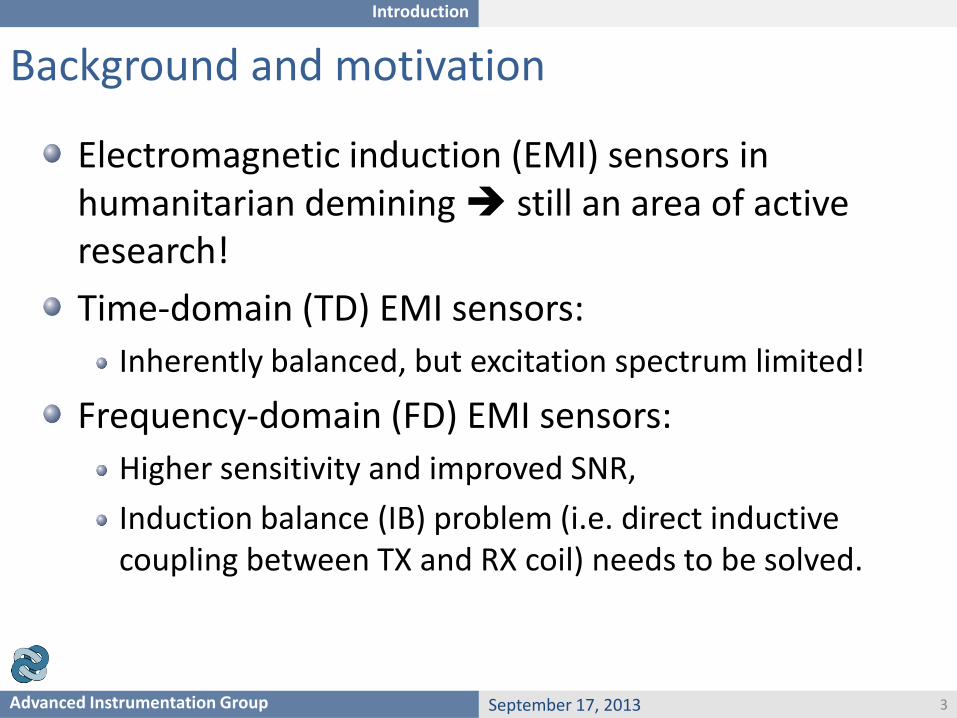
Electromagnetic induction (EMI) sensors in humanitarian demining still an area of active research!
Time-domain (TD) EMI sensors:
Inherently balanced, but excitation spectrum limited!
Frequency-domain (FD) EMI sensors:
Higher sensitivity and improved SNR,
Induction balance (IB) problem (i.e. direct inductive coupling between TX and RX coil) needs to be solved.
Introduction
3

September 17, 2013 Advanced Instrumentation Group
Induction balance problem
Suppression of primary (excitation) field achieved by sensing head geometry:
Introduction
4
a) “OO” coils b) “DD” coils c) “4B” coils
d) coaxial coils,
gradiometer conf. RX
e) concentric coils,
gradiometer conf. TX
f) concentric coils,
gradiometer conf. RX
Physical separation of coils,
Gradiometer configuration of RX coils,
Overlapping coils,
Orthogonal coils,
Transmitter-bucking,
…

September 17, 2013 Advanced Instrumentation Group
Sensing head - design objectives
Ultimate objective: handheld FD EMI landmine detector featuring model-based metal characterization and soil compensation.
Initial design requirements:
Sensing head – design and modeling
5
High sensitivity and dynamic range, Simple and compact geometry, High spatial resolution, Pinpointing accuracy, Good invertibility of measured data.
R1
R2
r
I1
I2
x
y
z
TX1 coil
TX2 coil
RX coil
I1≠ I2
active induction balance
transmitter-bucking configuration

September 17, 2013 Advanced Instrumentation Group
Sensing head model
Vertical component of magnetic field BZ as a function of radial distance r from the coil centre:
Sensing head – design and modeling
6
For a detector coil of radius r IB is obtained if:
for r ≤ R, inside loop (circular coil approx.)
Normalized voltages induced in RX coil in response to TX1 and TX2 coils.

September 17, 2013 Advanced Instrumentation Group
Induction balance sensitivity analysis
IB sensitivity to small perturbations of geometrical properties of coils (R1,R2,r) ?
For a given geometry: = -1.057, = -1.555, = 0.498
Sensing head – design and modeling
7
u
RS1
u
RS2
u
rS

September 17, 2013 Advanced Instrumentation Group
Active induction balance (AIB)
Excitation current in each transmitter coil controlled separately:
Active induction balance technique
8
Motivation:
Compensation of small imperfections of sensing head geometry and the effects of finite size coils,
Sensing head easier to produce,
Potential for more efficient soil compensation (lower loss of detector sensitivity / dynamic range).

September 17, 2013 Advanced Instrumentation Group
AIB implementation
Transmitter coil driven by current source transmitted field unaffected by changes in coil impedance, soil properties, lift-off and orientation of the sensing head.
Dual current source scheme:
Main (excitation) current source drives both TX coils,
Balancing current source additionally drives only inner TX coil.
Active induction balance technique
9
+
+
+Function
generator
Current
regulator
Feedforw.
controller
Feedback
circuitryBalance
setting
+1
-1
+1
-1
+-
x1
RS*
RS*
* Balance current setting resistors
TX1
TX2
Audio amp.
+
-
+
+
+
+
Power op. amp.

September 17, 2013 Advanced Instrumentation Group
Experiments and results
Dual current source and sensing head in transmitter-bucking configuration implemented as laboratory prototypes.
Induced voltage imbalance measured for passive IB and AIB at different frequencies (in absolute and relative terms).
Residual imbalances from passive IB can be effectively compensated by AIB.
Results and discussion
10

September 17, 2013 Advanced Instrumentation Group
Conclusions
For a design of novel, frequency-domain EMI landmine detector, we propose a sensing head configuration based on the transmitter-bucking approach.
Overall, IB sensitivities to small perturbations of sensing head geometrical properties are rather low.
Total sensor imbalances in absolute terms can become large, resulting in significant loss of sensitivity / dynamic range.
Prototype sensor with AIB and dual current source overcomes the limitations of passive IB.
Future work: further characterisation of the method, automatic compensation of soil-related imbalances.
Conclusions
11

September 17, 2013 Advanced Instrumentation Group
THANK YOU FOR YOUR ATTENTION!
Acknowledgement
12