Embed Size (px)
Citation preview

Active Earth Pressure Against Flexible RetainingWall For Finite Soils Under The Drum DeformationModeHu Weidong
Hunan Institute of Science and TechnologyZhu Xinnian ( [email protected] )
Hunan Institute of Science and TechnologyZeng Yongqing
Hunan Institute of Science and TechnologyXiaohong Liu
Hunan Institute of Science and TechnologyPeng Chucai
Hunan Institute of Science and Technology
Research Article
Keywords: active earth pressure, non-limit state, soil arch, differential level layer method, drumdeformation mode, �exible retaining wall
Posted Date: September 8th, 2021
DOI: https://doi.org/10.21203/rs.3.rs-877838/v1
License: This work is licensed under a Creative Commons Attribution 4.0 International License. Read Full License
Active earth pressure against flexible retaining wall for finite 1
soils under the drum deformation mode 2
Hu Weidong1; Zhu Xinnian*2; Zeng Yongqing 3;Liu Xiaohong4; Peng Chucai5 3
4
1 Professor, College of Civil Engineering and Architecture, Hunan Institute of Science and Technology, Yueyang 5
414000, China. Email: [email protected] 6
2 Lecturer, College of Civil Engineering and Architecture, Hunan Institute of Science and Technology, Yueyang 7
414000, China(Corresponding author). Email: [email protected] 8
3 Ph.D. College of Civil Engineering and Architecture, Hunan Institute of Science and Technology, Yueyang 9
414000, China. Email: [email protected] 10
4 Professor, College of Civil Engineering and Architecture, Hunan Institute of Science and Technology, Yueyang 11
414000, China. Email: 11991491@ hnist.edu.cn 12
5 Ph.D. College of Civil Engineering and Architecture, Hunan Institute of Science and Technology, Yueyang 13
414000, China. Email:[email protected] 14
Corresponding author: Zhu Xinnian*, Lecturer, Email: [email protected] 15
16
Abstract: A reasonable method is proposed to calculate the active earth pressure of finite soils based on the 17
drum deformation mode of the flexible retaining wall close to the basement’s outer wall. The flexible retaining 18
wall with cohesionless sand is studied, and the ultimate failure angle of finite soils close to the basement’s outer 19
wall is obtained using the Coulomb theory. Soil arch theory is led to get the earth pressure coefficient in the 20
subarea using the trace line of minor principal stress of circular arc after stress deflection. The soil layers at the top 21
and bottom part of the retaining wall are restrained when the drum deformation occurs, and the soil layers are in a 22
non-limit state. The linear relationship between the wall movement’s magnitude and the mobilization of the 23
internal friction angle and the wall friction anger is presented. The level layer analysis method is modified to 24
propose the resultant force of active earth pressure, the action point’s height, and the pressure distribution. Model 25
tests are carried out to emulate the process of drum deformation and soil rupture with limited width. Through 26
image analysis, it is found that the failure angle of soil within the limited width is larger than that of infinite soil. 27
With the increase of the aspect ratio, the failure angle gradually reduces and tends to be constant. Compared with 28
the test results, it is showed that the horizontal earth pressure reduces with the reduction of the aspect ratio within 29
critical width, and the resultant force decreases with the increase of the limit state region under the same ratio. The 30
middle part of the distribution curve is concave. The active earth pressure strength decreases less than Coulomb’s 31
value, the upper and lower soil layers are in the non-limit state, and the active earth pressure strength is more than 32

Coulomb’s value. 33
Key words: active earth pressure; non-limit state; soil arch; differential level layer method; drum deformation 34
mode; flexible retaining wall 35
36
Introducion 37
Deep foundation pits are often excavated near the basement of existing buildings in urban 38
and municipal engineering. The undisturbed soil between the retaining wall and the existing 39
basement’s outer wall is narrow and its width is limited, which is also the research object of this 40
paper. Row pile wall, underground diaphragm wall, and sheet pile wall have been great used in 41
enclosure structure of foundation pit engineering and slope engineering. The thickness of the 42
retaining wall structure is minimal compared with the height. The wall has obvious flexure 43
deformation, which can’t meet the rigid retaining wall’s assumption, called the flexible retaining 44
wall. The classical earth pressure theories of Coulomb and Rankine cannot accurately predict the 45
earth pressure on the flexible retaining wall. 46
The structural deformation of the retaining wall caused by the excavation of internal support 47
and anchor pull system can be classified into three types (Clough and O'Rourke 1990; Milligan 48
1983; Zhang et al.1998). The first type is a cantilevered triangle with the largest displacement at 49
the top of the wall. The second type is drum deformation because the upper part of the flexible 50
retaining wall is supported. The bottom of the wall is embedded in the soil, which shows that the 51
displacement of the top and bottom of the wall is unchanged. The abdomen of the retaining wall 52
structure protrudes into the foundation pit, and the displacement curve is parabolic. The third type 53
of deformation is the combination of the first two. For the supporting and anchoring flexible 54
retaining wall, the drum deformation mode bulging into the pit is the most typical one, which is 55
also the basis of studying other combined modes of wall movement. It is of great significance to 56
study the deformation’s behavior, the failure mechanism, and the earth pressure distribution. 57
The drum deformation mode of the flexible retaining wall is characterized by large 58
deformation in the middle and small deformation at both ends. The horizontal displacement of soil 59
is mostly parabolic. The earth pressure on the retaining wall is nonlinear along with the wall’s 60
height, which is affected by the magnitudes of displacement and the displacement mode of wall 61
movement. Milligan (1983) carried out the model test of flexible retaining wall with support at the 62

top, studied the relationship between the drum deformation of the wall and the displacement of the 63
soil, and the development of sliding surface behind the wall. Lu et al. (2003) carried out the active 64
earth pressure and displacement tests of a cantilever and single anchor flexible retaining wall, and 65
obtained the R-shaped distribution of active earth pressure along the anchored retaining wall. 66
Zhang et al.(1998) presented the relationship between the coefficient of earth pressure of sand and 67
the increment ratio of axial and lateral strain based on the triaxial test. They deduced the unified 68
expression of displacement and the calculation method of earth pressure under any displacement 69
state. Based on the previous experiments and numerical analysis, the calculation method of active 70
earth pressure resultant force and its distribution on flexible retaining walls under arbitrary 71
displacement is proposed by Ying et al. (2014). 72
Under the drum deformation mode, the top of the wall is constrained by the support, and the 73
soil layers constrain the bottom of the wall. The deformation feature can be seen as the upper wall 74
rotates outward around the top of the wall, while the lower wall rotates outward around the bottom 75
of the wall (Gong et al. 2005; Matsuzaw 1996; Wang et al.2003; Chang 1997; Fang 1986). There 76
is a relative displacement tendency between the upper and lower soils during the deformation, 77
resulting in the horizontal shearing stress, which cannot be ignored. Therefore, the coefficient and 78
distribution of active earth pressure are affected. The deformation and earth pressure distribution 79
of the soil layer near the top and bottom of the wall has RT mode and RB mode characteristics. 80
The existing theoretical research is still insufficient. Based on the relationship between the 81
unit earth pressure and the horizontal displacement, the calculation formulas (Zhang et al. 1998; 82
Xu 2000; Mei et al.2001) were put forward, but the relative displacement was not considered 83
under the drum deformation. The results show that the distribution of earth pressure is always 84
between the static and active states, which can’t reflect the redistribution of earth pressure caused 85
by the drum deformation of flexible retaining walls. Ying et al. (2008) considered the relative 86
displacement of the adjacent depth soil layers, but the earth pressure dropped sharply at the wall’s 87
maximum displacement, which was unreasonable. 88
The deformation of the soil layer near the top and bottom of the retaining wall is limited, and 89
it is impossible to reach a limit state in company with the soil layer in the middle abdomen. The 90
rotating angle of the retaining wall is small when in service, which makes the displacement of the 91
soil near the top and bottom of the wall very small, and it is not easy to reach the limit state. The 92
shearing strength of soil and friction between wall and soil can’t be fully mobilized, and they are 93

actually in a non-limit active state. The magnitude of active earth pressure is affected by the drum 94
deformation mode, which causes the redistribution of earth pressure. The soil layer’s active earth 95
pressure near the top and bottom of the wall increases due to the soil arching (Paik and Salgado 96
2003; Handy 1985; Hu et al. 2020a), while the active earth pressure of the soil layer in the middle 97
of the wall decreases relatively. 98
Therefore, to better study the active earth pressure against the flexible retaining wall, the wall 99
movement mode, the actual non-limit active state of the soil layer near the top and bottom of the 100
wall, and the soil arching should be taken into account (Lin et al. 2020; Hu et al. 2020a; Zhu and 101
Zhao 2014; Take and Valsangkar 2001; Liu 2018; Naki 1985). The soil behind the flexible 102
retaining wall near the outer wall of the existing basement or the vertical slope is filled with 103
limited width soil (Chen et al. 2019a; Chen et al. 2019b; Xie et al.2019; Hu et al.2020b), which 104
has attracted more and more attention in practical engineering. 105
The soil arch theory is led into this research based on the progressive rupture mechanism in 106
the cohesionless sand under drum formation mode. The differential level layer unit method is 107
applied to analyze the partition unit. Considering the shearing stress and the partial mobilization of 108
shearing strength and wall friction in a non-limit state, the distribution of the active earth pressure, 109
the resultant force’s magnitude, and the action point’s height are obtained. The model tests are 110
conducted to verify further the proposed method in the paper. 111
Analysis model of flexible retaining wall 112
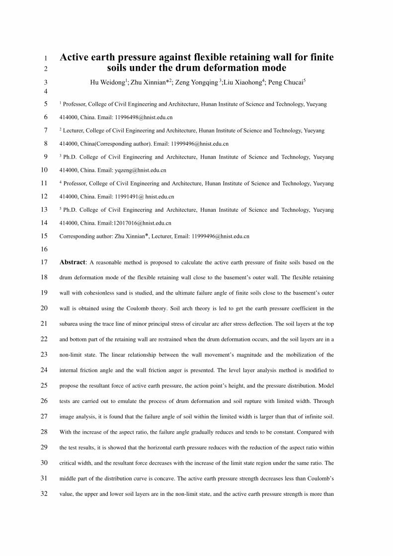
The retaining wall is close to the basement outer wall or vertical rock slope, and the height of 113
the retaining wall is H, as shown in Figure 1. Cohesionless sand is filled behind the retaining wall, 114
the narrow width is l=n∙H (n is the ratio of width to height). 115
The middle abdomen of the flexible retaining wall protrudes into the excavation under the top 116
strut’s support and the constraint of the embedded end at the bottom, forming a drum deformation. 117
The only rotation occurs at the top and bottom of the retaining wall, and its horizontal 118
displacement is assumed to be zero. It is assumed that the midpoint H/2 is the place of maximum 119
deformation and horizontal displacement. Because of the limited width of retaining sand, the slip 120
plane is cut off by the outer wall or rock slope and cannot fully develop to the sand top surface. 121
Thus, the height of the wall is divided into H1 and H2. The sliding surface is assumed to be a plane, 122
passing through the bottom of the wall and forming an angle β with the level plane. 123
Due to the different widths of the limited soil, the intersection point c of slip surface and 124

vertical external wall or rock slope may be higher or lower than the maximum horizontal 125
displacement of the midpoint, including two cases, as shown in Figure 1. When H1≤H/2, the soil 126
mass is divided into upper and lower areas with ce as the boundary. The area above the ce 127
boundary is the zone I, and the area below the ce boundary is divided into zones II, III, and IV 128
from top to bottom. The up thin layer at the maximum horizontal displacement is the intermediate 129
transition zone III (Figure 1 (a)). When the width is minimal, H1>H/2, the area below the ce 130
boundary in zone IV, and the area above the ce boundary is divided into zones I, II, and III from 131
top to bottom. The up thin layer at the maximum horizontal displacement is the intermediate 132
transition zone II (Figure 1 (b)). 133
134
(a)H1≤H/2 135
136
(b)H1>H/2 137
Fig.1 Slip surface 138
N
Wu
b
zoneⅡ
H
H/2
p
c
zoneⅣ
R
zoneⅢ
d
H1
Ea
a
e
H2
zoneⅠ
l
W
Eae
H2
zoneⅠ
H1
a
N
R
d
zoneⅣ
H
u
H/2
p
l
zoneⅡ
b
zoneⅢc

Based on the wall friction and the existence of force N, for simplifying the calculation, it is 139
approximately considered that the earth pressure distribution on the wall meets the triangular 140
distribution along with the height. Therefore, it is the same at the same depth (Jie 2019; Wang et al. 141
2014a; Hu et al.2020a). By introducing the parameter m, then: 142
21( )a a
HN mE E
H
(1) 143
Ea is the resultant force of active earth pressure acting below the normal, and its direction is δ 144
angle from the normal of the back of the wall. 145
Based on the Coulomb method, the vertical and horizontal equilibrium function of soil on the 146
sliding surface is derived. 147
2
2 2
1(2 tan )
2
sin [1 (1 tan ) ] cos cot( )[1 (1 tan ) ]a
nH n
En n
(2) 148
The extreme value of Ea can be solved ( / 0adE d ) to obtain the value of β of the most 149
dangerous sliding surface as the soil enters an active limit state. The value of the extreme thrust Ea 150
can be obtained by using Eq.(2) (Hu et al.2020a). 151
The active earth pressure coefficient 152
Firstly, taking the situation shown in Fig. 1 (a) as the research object, the earth pressure 153
coefficient and the soil arching are analyzed. ce is taken as the boundary line according to the 154
different boundary conditions of the finite soil. 155
156
Fig.2 Trajectory of minor principal stress of zone I 157
Q
dz
f
of
r
31
W
hQ
Q
Bz
H1
VQ
j
1
h 3
l
j
z
W
h

The upper zone I is located between the backs of the retaining wall and the outer wall. In the 158
process of drum deformation and ground subsidence, because of friction between two vertical 159
parallel walls, the stress deflection occurs due to the soil arch, and the horizontal stress on the 160
retaining wall is no longer minor principal stress. The horizontal layer unit at depth z (in zone I) is 161
taken for analysis. The minor principal stress trajectories of each point are connected to form a 162
continuous arch curve, as shown in Fig. 2. Although the stress and boundary conditions of the 163
retaining soil in the lower zones II, III, and IV are different from those in the upper zone I, the 164
vertical and lateral deformation are also limited by frictions (the interface friction between the 165
retaining wall and the retaining soil and the soil friction on the failure plane). Therefore, the 166
direction of the principal stress deflects, and its magnitude remains unchanged along the arch. 167
Taking the layer unit at depth z (in zones II, III and IV) for analysis shown in Fig. 3, each point’s 168
minor principal stress trajectories on the horizontal unit forms a half arch. Moreover, the 169
horizontal shearing stress exists on the level unit’s surface objectively, and the shearing stress of 170
each point is not equal because of the unequal deflection angle of each point. 171
172
Fig.3 Trajectory of minor principal stress in zone II,III,IV 173
The circular arch is employed generally for analysis by many scholars (Wang 2014b; Hu et 174
al.2020a; Lin et al. 2020; Cao et al.2019). Since the circular arch’s calculation results are close to 175
those of other shapes of arch curves, the circular arch stress trajectory is used to establish the 176
calculation model in this paper. 177
Q
1
dz
hQ
o
Q
f
h g
r
WH2
z
fvQ
g
Bz

After stress deflection occurs, an arched curve with radius r is formed at point f. The center of 178
the circle is point O. The vertical stress distribution on the layer unit at depth z is uneven 179
considering the soil arching effect. Herein, according to the study by Handy (1985) and Paik and 180
Salgado (2003), the lateral active earth pressure coefficient Kawn is defined as 181
hawn
v
K
(3) 182
Where h is the normal earth pressure on the interface between retaining wall and soil at the 183
depth z, v is the average erect pressure on the level at the same height. 184
The stress of point Q on the arch line is expressed as follows. 185
1
1
1
= (1 sin cos 2 )1 sin
= (1 sin cos 2 )1 sin
sin= sin 2
1 sin
vQ
hQ
Q
(4) 186
Where 1 is the major principal stress and θ is the deflection angle between the major principal 187
stress and the level at point Q. The deflection angles at point f and g are indicated as: 188
sin[ arcsin( ) ] / 2
sin
/ 4 / 2
f
g
(5) 189
Considering the symmetry of soil mass in zone I, half of the circular arch trajectory can be 190
taken for analysis. The horizontal span Bz is l/2, the deflection angle at point j is θj=π/2, and the 191
average vertical stress along the arch in zone I is 192
2
1 1
sin 2sin cos
3(1 sin )
j
f
vQ f
v
z
r d
B
(6) 193
In the formula, the curve radius of the minor principal stress arch curve is r194
/ (cos cos )z f jB . The lateral coefficient of active earth pressure Kawn1 in zone I can be 195
presented from Eq. (4) and Eq. (6), 196
1 2
3(1 sin cos 2 )
3(1 sin ) 2sin cos
fhawn
fv
K
(7) 197

The mean shearing stress of soil arching line in zone I is 198
3
1
sin 2sin (1 sin )
3(1 sin )cos
j
f
Q f
z f
r d
B
(8) 199
The average shearing stress coefficient k is defined as average shearing stress ratio to average 200
vertical stress on the level layer unit, which should be less than tanφ. 201
v
k
(9) 202
Thus, the average shearing stress coefficient k1 of soil in zone I can be given 203
3
1 3
2sin (1 sin )
3(1 sin )cos 2sin cos
f
f fv
k
(10) 204
To the lower soil in zones II, III and IV, the average vertical stress on the track line of minor 205
principal stress arching can be expressed as 206
3 3
1 1
sin 2sin (cos cos )
3(1 sin )(cos cos )
g
f
vQ f g
v
z f g
r d
B
(11) 207
Where, the radius r / (cos cos )z f gB . Similarly, the lateral coefficient of active earth 208
pressure Kawn2= Kawn3= Kawn4 and the coefficient of average shearing stress k2= k3= k4 can be 209
obtained in zones II, III and IV 210
2 2 2
3(1 sin cos 2 )
3(1 sin ) 2sin (cos cos cos cos )
fhawn
f g f gv
K
(12)
211
3 3
2 3 3
2sin (sin sin )
3(1 sin )(cos cos ) 2sin (cos cos )
g f
f g f gv
k
(13) 212
Suppose the ultimate rupture angle is β=π/4+φ/2, Kawn1=Kawn2, k1=k2. If β=π/4+φ/2 and δ=0, 213
Eqs. (7) and (12) is able to transform into Kawn1,2=tan2(π/4-φ/2), that is Rankine coefficient. 214
Furthermore, taking the situation shown in Fig. 1 (b) as the research object, the coefficient of 215
earth pressure and soil arching are analyzed according to the same method above. Then, we can 216
get the lateral active earth pressure coefficients Kawn1, Kawn2, Kawn3, and average shearing stress 217
coefficients k1, k2, k3 in zones I, II, and III. 218
1 2 3 2
3(1 sin cos 2 )
3(1 sin ) 2sin cos
f
awn awn awn
f
K K K
(14) 219

3
1 2 3 3
2sin (1 sin )
3(1 sin )cos 2sin cos
f
f f
k k k
(15)
220
The coefficient of lateral active earth pressure Kawn4 and average shearing stress k4 in zone IV 221
are obtained. 222
4 2 2
3(1 sin cos 2 )
3(1 sin ) 2sin (cos cos cos cos )
f
awn
f g f g
K
(16)
223
3 3
4 3 3
2sin (sin sin )
3(1 sin )(cos cos ) 2sin (cos cos )
g f
f g f g
k
(17) 224
Parameter value in non-limit state 225
The horizontal displacement of the retaining wall is s under the drum movement mode, and 226
the magnitude of displacement at the middle point is the largest, which value is smax. Assuming 227
that the horizontal displacement required for the soil to enter the full limit state is sa, the area with 228
the displacement s≥sa is the full limit state area, where the internal friction angle of the fill and 229
the external wall friction angle are fully mobilized. In this paper, the region is defined as the 230
intermediate transition region. 231
The area with horizontal displacement s<sa of retaining wall is a non-limit state area. In the 232
non-limit state, because of the small magnitude of displacement, the soil friction angle φ′ and the 233
wall friction angle δ′ partial mobilize that their values are between the initial state values φ0, δ0, 234
and the ultimate state values φ, δ, respectively. Considering that the mobilization of φ′ and δ′ are 235
affected by the magnitude of horizontal displacement of the retaining wall, it is assumed that φ′ 236
and δ′ increase linearly with the increase of horizontal displacement, the following expression is 237
given by 238
-1
0 0
-1
0 0
0 ,2 2
,2 2 2
' tan [tan (tan tan )]/ 2 / 2
'
' tan [tan (tan tan )]/ 2 /
2
,2 2 2
H zz
H z H zz
H zz
z
H z
H z
HH
z
(18) 239
and 240

-1
0 0
-1
0 0
0 ,2 2
,
' tan [tan (tan tan )]
2
/ 2 / 2
'
' tan [tan (tan
2 2
tan )]/ 2 / 2
2
,2 2
H zz
H z H z
z
z
H zz H
H z
H z
H z
(19) 241
Where, 242
-1 00
0
1sin [ ]
1
K
K
(20) 243
In which,
244
0 1 sinK
(21) 245
In general, δ=2φ/3 and δ0=φ/2. The variation of φ′ and δ′ along the retaining wall under drum 246
deformation mode is shown in Figure 4. 247
248
Fig.4 φ′ and δ′ along the height of retaining wall 249
250
(a)H1≤H/2 251
H/2
δ0
δ
s<sa
φ0
s≥sa△Z
δ
H/2-△z/2
δ0
smax φ′sa
δ′
s<sa
φ
φ0
φ
H
c
p
H/2
l
h
sa b
u
zoneⅡ
zoneⅣ
△Z
e
H2
zoneⅠ H1
smax
d
zoneⅢ
a

252
(b)H1>H/2 253
Fig.5 Drum deformation displacement mode of flexible retaining wall 254
The height of the intermediate transition zone is set as ∆z=x·H, the soil mass within the 255
height ∆z reaches the active limit equilibrium state. x is the ratio of soil layer height entering the 256
limit state along the retaining wall. For the first case of H1≤H/2, as shown in Fig. 5 (a), the depth 257
from the top surface of the transition zone to the fill’s top surface is h=H/2- ∆z/2. In this paper, the 258
depth h is limited to [H1, H/2], where h tends to H1with ∆z increases. When ∆z/2≥H/2- H1, the 259
original zone II disappears, and the depth of the top surface of the transition zone is calculated as 260
h= H1. When ∆z→0, h tends to H/2 and is calculated as h= H/2, which is the thin transition layer 261
shown in Fig. 1 (a). 262
For the second case of H1>H/2, as shown in Figure 5 (b), the height from the bottom of the 263
transition zone to the top of the fill is set as h´=H/2+∆z /2. In this paper, the depth h´ is limited to 264
[H/2, H1], where h´ tends to H1 with ∆z increases. When ∆z/2≥H1-H/2, the original area III 265
disappears, and the depth of the bottom surface of the transition zone is calculated as h´= H1. 266
When ∆z→0, h´ tends to H/2 and is calculated as h´= H/2, which is the thin transition layer shown 267
in Figure 1 (b). 268
Solution for active earth pressure strength 269
The shearing stress on the level unit surface is normally not considered under the translation 270
mode (T) because the soil mass moves as a whole, and there is no relative movement between the 271
horizontal soil layers. However, under the drum movement mode, the flexible retaining wall can 272
b
zoneⅣ
H
p
c
smax
H1
zoneⅡ△Z
d
u
sa
l
h′H/2
a
ezoneⅢ
H2
zoneⅠ

be regarded as the upper retaining wall rotating about the top of the wall (RT) and the lower 273
retaining wall rotating about the bottom of the wall (RB). Each soil layer produces relative motion 274
in the rotation direction with respect to the below layer. There must be level shearing stress 275
between the upper and lower soil. The distribution of shearing stress is very complex, and it will 276
affect the moment balance condition. If the moment equilibrium condition is not involved in the 277
derivation, then the specific distribution of shear stress is not concerned (Liu et al.2016, 2018). 278
Nevertheless, different stress distribution assumptions on the horizontal plane will not affect two 279
static equilibrium of force along with the horizontal and vertical directions. 280
In this paper, the differential level layer method is introduced. According to the relative 281
movement trend of the horizontal layer unit of the soil wedge behind the wall, the action direction 282
of the friction shearing stress between the level layer units in each zone is determined (Chen et al. 283
2009; Hu et al.2020a 2020b; Liu et al. 2016). Under the condition of satisfying the balance of 284
forces, the active earth pressure differential equation in a non-limit state is established, and then its 285
distribution is discussed. 286
Zone I 287
The level layer unit in zone I is shown in Figure 6, and the static equilibrium equations are 288
established. 289
290
Fig.6 Forces acting on level units in zone I 291
1 1 1 0h ndz dz nHd (22) 292
1 1 1 1 0w v ndz nHd dz dw (23) 293
In which, the second order differentiation has been omitted, σv1 is the vertical stress on the layer 294
unit at depth z, and σh1 is the lateral active earth pressure. 295
1 1 1h awn vK (24)
296
τ1 is the horizontal shearing stress on the surface of the layer unit, assuming it is average 297
n1
n1
v
1
h1 1
dw
1
d
v+
dz
1
1
1
+ d
v
w
1
1

distribution, it can be obtained. 298
1 1 1vk (25) 299
Where τw1 is the shearing stress on the interface, and the magnitude of τw1 is: 300
1 1 tan 'w h (26) 301
σn1 is the horizontal lateral pressure on the outer wall at depth z, and τn1 is the shearing stress. τn1
302
can be expressed by 303
1 1 tan 'n n (27)
304
dw1 is the self-weight of the level unit in zone I, and its magnitude is obtained as: 305
1dw nHdz (28) 306
In general, there are 307
1 11 1
2 tan '(1 tan ') 0v awn
v
d Kk
dz nH
(29) 308
When z=0, σv1=0 is regarded as the boundary condition of zone I, the first-order linear differential 309
equation (Eq.29) can be solved as follows. 310
( )
1
Bz
Av e
B B
(30) 311
In which 312
1
1
1 tan '
2 tan 'awn
A k
KB
nH
(31) 313
When z=H1, σv1=D1 can be regarded as the boundary condition of equivalent load on the surface of 314
the isolated body in zone II. 315
1( )
1
BH
AD eB B
(32) 316
Zone II 317
318
Fig.7 Forces acting on level units in zone II 319
n2
2
n
+
2
v2
2
2
2
w
2
d
dz
2
h2
+
d
v
2
dw
v

On the basis of the static equilibrium conditions of horizontal and vertical directions acting 320
on the layer unit (Figure 7), the equation is established. The second-order differential components 321
are omitted to obtain. 322
2 2 2 2 2cot ( )cot cot 0h n ndz dz d H z dz dz (33) 323
2 2 2 2 2 2cot ( )cot cot 0w v v n ndz dz H z d dz dz dw (34) 324
Where σv2 is the mean vertical normal stress on the surface of layer unit, and σh2 is the lateral 325
active earth pressure. 326
2 2 2h awn vK (35) 327
τ2 is the level shearing stress on the soil layer unit. It is assumed to be uniformly distributed, and 328
its magnitude is expressed as follows: 329
2 2 2vk (36) 330
Where τw2 refers to the shearing stress on the interface and its expression is 331
2 2 tan 'w h (37) 332 σn2 is the normal stress distributed uniformly on the rupture surface. τn2 is the shearing stress 333
distributed uniformly, the formula is 334
2 2 tan 'n n (38) 335
In which dw2 is the self-weight of level layer element in zone II, and its expression is 336
2 ( )cotdw H z dz (39) 337
By synthesizing the above formula, the first order differential equation is obtained, 338
2 2 0( )
v vdF G
dz H z
(40) 339
in which, 340
2
2 2 2
(1 )
tan [ tan ' cot ( cot )]
cot tan '
cot tan ' 1
awn awn
F k C
G K C k K
C
(41) 341
Eq. (40) and Eq. (32) are solved to present the following equation. 342

12 1
1
( )( )[ ]( )
G
Fv
H HH z H zD
F G F G H H
(42) 343
By substituting Eq. (42) into Eq. (35), the horizontal active earth pressure in zone II is derived. 344
When z = h, σv2= D2 is regarded as the boundary condition of equivalent load on zone III.
345
12 1
1
( )( )[ ]( )
G
FH HH h H h
D DF G F G H H
(43)
346
Zone III 347
348
Fig.8 Forces acting on level units in zone III 349
Zone III is the middle transition layer, in which the shearing strength of the soil is fully 350
mobilized, the internal friction angle of fill is φ′=φ, and the external friction angle between walls 351
and soils is δ′=δ. The mean vertical compressive stress on the top of layer (z = h) is σv3= D2, and 352
the mean vertical compressive stress at the bottom of the layer is σ′v3=σv3+∆σv3, as shown in 353
Figure 8. When ∆z is large, the whole isolator in zone III is taken as the research object, and the 354
horizontal and vertical static balance equations are established as follows: 355
'
3 3 3 3 33( ) ( )cot ( )cot sin( ) 0
2 2 2 2v vh
z H H zh k H h k R
(44) 356
and 357
'
3 3 3 33tan ( ) ( )cot ( )cot cos( ) 0
2 2 2 2v vh
z H H zh H h w R
358
(45) 359
in which, 3h
is the mean lateral horizontal stress. 360
'
3 333( )
2
v vawnh
k
(46) 361
Thus, 362
'
3 3 0v vQ S T
(47) 363
in which, 364
h3
R3+
△Z
=
3
=
3
w
3′ 3
v′
△w3
3v
△
+3
3v 3
v
△
3

3 3
3 3
1( )cot [ cos( ) sin( )] ( )[cos( ) tan sin( )]
2 2 2
1( )cot [ cos( ) sin( )] ( )[cos( ) tan sin( )]
2 2 2 2 2
1 3cot sin( )( )( )
2 2 2 2 2
awn
awn
H zQ H h k k h
H z H zS k k h
H z H zT h h
365
(48) 366
When z=h, σv3= D2 is substituted into equation (47) as a known loading condition, σ′v3 at the 367
bottom of the layer can be obtained. Assuming σ′v3= D3, it can also be regarded as the equivalent 368
load on the insulator’s top surface in zone IV. The distribution of σh3 along the height ∆z of the 369
middle transition zone can be approximately considered as a linear distribution, and its expression 370
is 371
3 3 2 2 3[ ( ) ]( / 2 / 2 )
h awn
h zk D D D
H z h
(49)
372
When ∆z→0, h= H/2 is taken for calculation, and zone III is a thin transition layer. In 373
accordance with its equilibrium conditions, the solution can be obtained. 374
3 v3v3
3
-2=
tan( )
k
k
(50) 375
The mean vertical stress at the bottom of the thin transition level unit is 376
' 3v3 v3 v3 v3
3
- tan( )=
tan( )z h
k
k
(51) 377
Therefore, when ∆z→0, the mean pressure stress at the bottom of the thin transition layer is taken 378
as the equivalent load on the insulator’s top surface in zone IV, and the formula is as follows. 379
33 2
3
- tan( )=
tan( )z h
kD D
k
(52) 380
Zone IV 381
382
Fig.9 Forces acting on level units in zone IV 383
4
d
4
4
w
n
4
4
4v
n4
4
+v v4
dw
d
+
dz
4
h4

From the static equilibrium conditions of the unit in horizontal and vertical directions (in 384
Figure 9), we can get: 385
4 4 4 4 4cot ( )cot cot 0h n ndz dz d H z dz dz (53) 386
4 4 4 4 4 4cot ( )cot cot 0w v v n ndz dz H z d dz dz dw (54) 387
In which, σv4 is the mean direct stress on the layer unit’s surface at depth z, andσh4 is the 388
horizontal active earth pressure. 389
4 4 4h awn vK (55) 390
τ4 is the level shearing stress on the surface of the layer unit, assuming a mean distribution, and its 391
expression is: 392
4 4 4vk (56) 393
Where τw4 is the shearing stress on the contact surface, and its expression is: 394
4 4 tan 'w h (57) 395 σn4 is the normal stress and τn4 is the friction shearing stress, which is expressed as: 396
4 4 tan 'n n (58) 397
In which, dw4 is the self-weight of level layer unit in zone IV, which can be expressed as: 398
4 ( )cotdw H z dz (59) 399
By synthesizing the above formula, the first order differential equation can be get, 400
4 4 0( )
v vdJ L
dz H z
(60) 401
in which, 402
4
4 4 4
(1 )
tan [ tan ' cot ( cot )]
cot tan '
cot tan ' 1
awn awn
J k C
L K C k K
C
(61) 403
By using the boundary condition, i.e. the mean vertical stress σv4= D3 on the top of zone IV, we 404
can solve the differential equation (60) and get 405
4 3
( ) ( / 2 / 2)[ ]( )
/ 2 / 2
L
Jv
H z H z H zD
J L J L H z
(62) 406

By substituting the above equation (62) with equation (55), the lateral active earth pressure in zone 407
IV is generated. 408
For calculating the second case of H1>H/2, the same method can be used for analysis. Given 409
the length of the paper, a detailed derivation is omitted. When z=0, σv1=0 is the boundary 410
condition of zone I, and the vertical stress on the surface of the level unit at depth z in zone I is 411
obtained as: 412
( )
1
Bz
Av e
B B
(63)
413
When z=H/2-∆z/2, σv1=D1 is regarded as the equivalent load on the top surface of zone II. 414
( )2 2
1
B H z
AD eB B
(64) 415
Taking into account the overall static balance of the middle transition layer in zone II, we can 416
get 417
'
2 2' ' ' 0v vQ S T
(65) 418
in which, 419
2 2
2 2
' tan ( ) ( tan 1)2 2
' tan ( ) ( tan 1)2 2
' ( )2 2
awn
awn
z HQ k h k nH
z HS k h k nH
z HT nH h
(66)
420
Taking σv2= D1 at depth z= H/2-∆z/2 as the known loading conditions, σ′v2 at the bottom of 421
the layer can be obtained. Assuming σ′v2= D2, it can also be regarded as the equivalent load on the 422
top surface of zone III. 423
Similarly, the distribution of the earth pressure σh2 along the height ∆z of the middle 424
transition zone can be considered a linear distribution approximately. 425
2 2 1 1 2
/ 2 / 2[ ( ) ]
( / 2 / 2)h awn
H z zk D D D
z h H
(67)
426
Considering the equivalent load on the top surface of zone III, the vertical stress on the surface 427
of the level unit at depth z is 428
'( )
'3 2( )
' '
Gh z
Fv D e
G G
(68) 429
in which, 430

3
3
' 1 tan '
2 tan '' awn
F k
KG
nH
(69) 431
Then we can take σv3=D3 at depth z= H1 as the known loading conditions of equivalent load on the 432
top surface of zone IV. 433
1
'( )
'3 2( )
' '
Gh H
FD D eG G
(70) 434
The vertical stress in zone IV is 435
24 3
2
( )( )( )
L
Jv
HH z H zD
J L J L H
(71) 436
Resultant force and height of action point 437
When σh1 , σh2, σh3, and σh4 are integrated along with the wall height, the horizontal 438
component Eax of resultant force for earth pressure on the whole retaining wall can be obtained. 439
1
1
1
( /2 /2
1 2 3 40 ( /2 /2)
22( )
21 11 12
2 2 321 2 3
2
4
[ 1] ( )2 2
( )[( )( ) ] ( )( )2 2 2
( )[
8( )
H h H z H
ax h h h hH h H z
BH
awnAawn
G
awn Fawn
awn
E dz dz dz dz
KH HA hK e Hh HH
B B F G
FK D DH H h H zD h H H K h
F G F G H
K H z
J L
3( ) 4 ]H z JD
(72) 440
The expression of resultant force is given by 441
cos
axa
EE
(73) 442
The height y of the point of application of the resultant force is as follows 443
1
1
1
( /2 /2)
1 2 3 40 ( /2 /2)
2 2( )
1 11 1 22 2
3 3 22 2 22 1
2
( ) ( ) ( ) ( )
( ) ( )2
( ) ( ) ( ) ( )3( ) 21
H h H z H
h h h hH h H z
ax
BH
awn Aawn
awn awn
ax
H z dz H z dz H z dz H z dzy
E
K H AH A A AHH K e H
B B B B B
K FK H H hH h H D h H
F G G F F G H
E
2
2
32 3
2
4 3
3( )( )( )
4 2 2 2 2
( ) [ ( ) 6 ]
24( 2 )
G
F
awn
awn
H
K H z H zD D h h
K H z H z JD
L J
(74) 444

In the first case, when ∆z/2≥H/2- H1, the depth of the top surface of the transition zone is h= 445
H1, and the calculation height [H1, h] of zone II is zero. In the calculation formula of Eax and y, the 446
calculation components in zone II are zero, and the original zone II is canceled. For the second 447
case, when ∆z/2≥H1- H/2, the calculated height of zone III is zero, and zone III is actually 448
canceled. 449
When the aspect ratio n is large, the slip plane slides out from the soil’s top surface. In this 450
paper, H1=0, σh1 in the zone I is always zero, and the calculation components of zone I in the 451
calculation formula of Eax and y are all zero. In fact, the original zone I has been canceled, and this 452
problem has developed into the earth pressure problem of infinite soil. 453
Model test 454
As shown in Figure 10, the self-made model is used for the experimental study (Toufigh 2012; 455
Toufigh et al. 2018 ). The movable baffle on the left side of the sandbox is polypropylene plate, 456
the fixed baffle on the right side is steel plate, the front side baffle is tempered glass, and the 457
backside baffle is frame steel plate, simulating the flexible retaining wall close to the outer wall of 458
the basement. The real object of the test model device is shown in Figure 11. 459
460
Fig.10 Construction detail of test box(unit: mm) 461
462
Motor3
Clamp steel bar
Screw Movable retaining wall
Fixed retaining wall
1200
Motor1
Motor2
Steel pedestal
700
1800
500
Control cabinet

(a) Front view 463
464
(b) Back view 465
466
(c) Top view 467
Fig.11 Entity of test box 468
469 Fig.12 Drum deformation mode of flexible retaining wall 470
Three motors are installed on the outer side of the sand loading box, as shown in Figure 12. 471
Curved steel base plate
Motor3
s
l
Motor2
Fixed retaining wall
H
Movable retaining wall
Motor1

During the test, the upper and lower motors do not operate (simulating that the top of the retaining 472
wall is supported and the bottom of the retaining wall is embedded). When the middle motor is 473
running, the transmission shaft rotates slowly. The center of the movable baffle gradually moves 474
horizontally outward, forming a certain horizontal displacement and realizing the drum-shaped 475
deformation displacement mode. 476
477
Fig.13 Layout of earth pressure cells(unit: mm) 478
The earth pressure is measured by five CYY9 micro earth pressure gauges arranged on the 479
movable retaining wall, with a measuring range of 5kPa and a size of Ф 22mm × 13mm. The 480
groove is excavated along the vertical centerline of the movable baffle at different depths, and the 481
micro earth pressure gauges are embedded. The groove’s depth is the same as the thickness of the 482
gauges so as to reduce the influence of the gauges protruding from the baffle. Then, a hole is 483
drilled at the groove side to lead out the wire of the earth pressure gauge from the back of the wall, 484
as shown in Figure 13. 485
Four groups of soil pressure tests were carried out in this model test, and the specific test 486
parameters are shown in Table 1. The mechanical parameters of sand samples are cohesion c=0, 487
internal friction angle φ=36.5°, wall friction angle δ=24.3°, and unit weight of the tested sand 488
specimen γ=15kN/m3. 489
Table 1 Parameters of tests 490
Number Height/m Width/m Ratio of width to height
1# 0.50 0.10 0.2
2# 0.50 0.15 0.3
3# 0.50 0.20 0.4
4# 0.50 0.25 0.5
600
85
Soil pressure gaugeT2
85
85
130
400
85
T3
T1
T5
30
T4
H=500

Soil deformation analysis 491
Taking the limited width as the PIV analysis area, image processing is carried out (Khosravi 492
et al. 2013; Hu et al.2020b). The deformation displacement diagram of different width sand (n= 493
0.2, 0.3, 0.4, 0.5, 0.7) under the drum movement mode is gained, as shown in Figure 14. 494
(a)n=0.2
(b)n=0.3
(c)n=0.4
(d)n=0.5
(e)n=0.7
Fig.14 Displacement fields of soil for different n (H=500mm) 495
As shown in Figure 14, the sliding failure surface is a plane developing upward from the 496
bottom of the movable baffle. With the increase of the filled sand’s width, the intersection of the 497
slip plane and fixed baffle moves upward until the slip plane slides out from the filled sand’s top 498
surface. When the ratio of width to height increases from 0.4 to 0.5, the intersection point of the 499
slip plane gradually changes from fixed retaining wall to sand top surface. Therefore, it can be 500
judged that the critical ratio of width height ratio of the finite soil in the model test is between 0.4 501
and 0.5. When the sand width is greater than the critical width, the retaining soil is considered 502
semi-infinite. 503
The ultimate fracture surface inclination angle is measured and compared with that calculated 504
on the basis of the generalized Coulomb method, as shown in Table 2. It can be seen that the 505
model test results are close to the theoretical calculation results in the limited width range. With 506
the increase of aspect ratio, the ultimate fracture angle decreases gradually and becomes stable. 507
The experimental analysis shows that the fracture angle β approaches to π/4+φ/2=63.25° under the 508
infinite width (width height ratio n= 0.5, 0.7). 509
Table 2 Slip surface inclinations under different n 510
Number Ratio of width to height Test result
/(°)
Calculation result
/(°)
1# 0.2 66.0° 64.22°
2# 0.3 64.5° 63.20°
3# 0.4 64.5° 62.07°

4# 0.5 63.5° 60.86°
5# 0.7 63.5° 60.08°
Earth pressure test results 511
By using the theoretical method in this paper, the distribution of lateral active earth pressure 512
with different ratios (n= 0.1, 0.2, 0.3, 0.4, 0.5) in the model test is calculated, as shown in Figure 513
15. 514
515
(a) x=0.1 516
517
(b) x=0.2 518
519
(c) x=0.3 520

521
(d) x=0.4 522
523
(e) x=0.5 524
Fig.15 Theoretical calculation results under different x. 525
526
(a) Resultant force 527
528

(b) Subtraction of prediction and Coulomb’s solution 529
Fig.16 Comparison of theoretical solution and Coulomb’s solution 530
The theoretical calculation solution shows that the active earth pressure in the figure is 531
nonlinear along with the height of the wall. The lateral earth pressure ruduces with the ruduce of 532
ratio within the limited width. When the ratio decreases to n= 0.1, the lateral earth pressure 533
decreases significantly. As the limit state region (x from 0.1 to 0.5) increases, the lateral earth 534
pressure near the retaining wall’s top and bottom decreases gradually. In contrast, the lateral earth 535
pressure in the middle of the retaining wall does not change significantly. 536
The resultant force increases with the increase of width to height and decreases with the rise 537
of limit state area under the same ratio. When the width (reaching and exceeding the critical width) 538
and the limit state region increase, the resultant thrust approach to that of Coulomb’s result, which 539
is consistent with the previous study, as shown in Figure 16(a). E'ax is obtained by subtracting the 540
prediction and Coulomb's solution. Figure 16(b) shows the difference at different x. 541
Figure 17 shows the comparison of the theoretical calculation of lateral earth pressure 542
distribution with the test results. It can be seen from the figure that the initial horizontal 543
displacement of the retaining wall is smaller under the same ratio. The limit state region is small 544
and only confined to the middle part of the wall. The lateral earth pressure on the upper and 545
bottom of the wall is relatively large and highly nonlinear. With the increase of the drum 546
deflection, most middle areas enter the active limit state, and the horizontal displacement increases 547
while the earth pressure decreases. With the increase of the limit state region (x from 0.1 to 0.5), 548
the horizontal lateral earth pressure distribution tends to be linearized gradually, and it is close to 549
Coulomb’s distribution of finite soil. 550
551
(a) n=0.2 552

553
(b) n=0.3 554
555
(c) n=0.4 556
557
(d) n=0.5 558
Fig.17 Comparison of theoretical calculation with experimental results 559
The distribution of the earth pressure on the retaining wall calculated theoretically is 560
consistent with that of the model test, and the distribution of the horizontal earth pressure in the 561
middle area is concave. The drum deformation mode of retaining wall under different aspect ratio 562
can be deemed that the upper part rotates about the top of the wall and the lower part rotates about 563
the bottom of the wall. The supporting anchor structure restrains the upper part of the retaining 564
wall, and the bottom is restrained by the fixed end, which makes the upper and bottom soil layers 565
fail to reach the limit state completely. They are still in the active middle state, that is, the 566
non-limit active state, and the shearing strength of the soil is insufficient. Therefore, the earth 567
pressure distribution of the upper and the bottom measuring points on the retaining wall are 568
greater than Coulomb’s solution to the finite soil, while the middle area is completely in the active 569

limit state, and the earth pressure distribution of the middle measuring points are very close to the 570
Coulomb’s solution to the finite soil. 571
572
Fig.18 Active earth pressure distribution with different internal friction angle 573
The internal friction angle is an important factor affecting the active earth pressure. When n = 574
0.3 and x = 0.2, the active earth pressure decreases with the increase of internal friction angle, as 575
shown in Figure 18. The active earth pressure without considering the soil arching is calculated 576
and compared with the theoretical solution in this paper, as shown in Figure 19. When the soil 577
arching is not considered, the active earth pressure acting on the upper part of the retaining wall is 578
almost the same as considering the soil arching. However, the earth pressure acting on the middle 579
and lower part of the retaining wall is obviously less than the earth pressure considering the soil 580
arching. In particular, the earth pressure in the transition zone decreases obviously. 581
582
Fig.19 Theoretical calculation results with arching and without arching (n=0.3) 583
Verification by comparison 584
Taking Lu's model test (2003) as an example, dry sand is used in the test, γ=16kN/m3, φ=31°, 585
δ=2φ/3, and the height of the flexible retaining wall with a single anchor is 2m. The displacement 586
of the wall under each excavation condition is typical drum deformation. Using the theoretical 587
method in this paper, the lateral earth pressure distribution is calculated for soils with infinite 588

width (the ratio of width to height is taken as n=0.5). The distribution of earth pressure at different 589
excavation depths obtained by this method, Ying’s method (2014), and Lu's test (2003) is shown 590
in Figure 20. 591
The calculated results of the proposed method are close to the calculated results of Ying 592
(2014) and the measured values of the model test by Lu (2003), and the earth pressure distribution 593
law is the same. The results show that the earth pressure on the middle part of the retaining wall 594
decreases with the increase of the drum deformation and the horizontal displacement, even less 595
than the Coulomb earth pressure strength. The earth pressure strength on the upper and lower part 596
of the retaining wall is greater than Coulomb’s solution owing to the effect of soils being in a 597
non-limit state. 598
599
(a) Excavation depth of 30 cm 600
601
(b) Excavation depth of 60 cm 602

603
(c) Excavation depth of 90 cm 604
Fig.20 Distributions of horizontal earth pressures 605
Conclusion 606
(1) Based on the characteristics of the drum deformation mode of the flexible retaining wall 607
close to the outer wall of the basement, four zones are divided to establish the mechanical analysis 608
model for the solution of the active earth pressure. The analysis model takes account of the 609
relative movement trend of the fill with the limited width. 610
(2) The coefficient of active earth pressure is obtained using the soil arch theory and 611
considering the horizontal shearing stress between differential layers. Considering the drum 612
deformation of the retaining wall and the non-limit state of upper and lower soil layers, the linear 613
relationship between the mobilization of internal friction angle and external friction angle and the 614
magnitude of displacement is presented, and the differential layer analysis method is modified. 615
(3) The model tests are conducted, it is found that the failure angle reduces gradually and 616
becomes stable with the increase of the ratio of width to height. When the ratio increases to 617
infinite soil, the failure angle approaches π/4+φ/2. 618
(4)The test results show that the active earth pressure of soils with finite width is nonlinear, 619
and the lateral earth pressure reduces with the reduction of the ratio of width to height in the 620
critical width range. As the limit state region increases, the resultant force of earth pressure 621
decreases under the same ratio of width to height. 622
(5)The earth pressure strength on the upper and bottom parts of the retaining wall is greater 623
than the Coulomb solution for finite soil. The earth pressure strength on the middle part of the 624
retaining wall decreases continuously, which is less than the Coulomb earth pressure strength. The 625

concave in the middle of the distribution curve is close to a linear line, and the lower part of the 626
distribution curve has higher nonlinearity. 627
628
Data Availability Statement:All data, models, and code generated or used during the study 629
appear in the submitted article. 630
Author Contributions: H.W.D. contributed to the idea and funding support for the paper, H.W.D. 631
and Z.X.N. carried out the analytical derivations and numerical examples, H.W.D., Z.X.N. and Z. 632
Y.Q. carried out the model tests, L.X.H. and P.C.C. contributed to the supervision and revision. 633
Acknowledgments:The work is supported by Natural Science Foundation of Hunan Province, 634
China (Grant No. 2017JJ2110), Key Scientific Program of Hunan Education Department, China 635
(Grant No. 20A228) and The Program of Hunan Province Education Department, China (Grant 636
No.19C0870) 637
Conflicts of Interest: The authors declare no conflict of interest. 638
639
References 640
Cao, W. G.(2019). “Calculation of passive earth pressure using the simplified principal stress trajectory method on 641
rigid retaining walls.” Computers and Geotechnics, https://doi.org/10.1016/j.compgeo.2019.01.021. 642
Chang, M. F. (1997). “Laterals earth pressure behind rotating walls.” Canadian Geotechnical Journal, 34(2), 643
498-509. 644
Chen,F. Q., Lin,Y. J.,and Li,D. Y.(2019a).“Solution to active earth pressure of narrow cohesionless backfill against645
rigid retaining walls under translation mode.” Soils and Foundations, 59(1), 151-161. 646
Chen, F.Q., Yang, J.T., and Lin, Y. J. (2019b). “Active earth pressure of narrow granular backfill 647
against rigid retaining wall near rock face under translation mode.” International Journal of Geomechanics, 648
19(12), 1943-5622. 649
Chen, L., Zhang, Y.X., and Ran, K.X. (2009). “Method for calculating active earth pressure considering shear 650
stress.” Rock and Soil Mechanics, 32(Supp.2), 219-223. 651
Clough, G.W., and O'Rourke T.D.(1990). “Construciton induced movements of institu walls.” Specialty 652
Conference on Design and Performance of Earth Retaining Structures, Atlantic, 439-470. 653
Fang, Y. S., and Ishibasbi, I. (1986). “Static earth pressures with various wall movements.” Journal of 654
Geotechnical Engineering, ASCE, 112(3), 317-333. 655
Gong, C., Yu, J. L., Xu, R. Q., and Wei, G. (2005). “Calculation of earth pressure against rigid retaining wall 656
rotating outward about base.” Journal of Zhejian University, 39(11), 1690-1694. 657
Handy, R. L. (1985). “The arch in soil arching.” Journal of Geotechnical Engineering, 111(3), 302-318. 658
Hu, W.D., Liu, K.X., Zhu, X.N., et al. (2020a). “Active Earth Pressure against Cantilever Retaining Wall adjacent 659

to Existing Basement exterior Wall.” International Journal of Geomechanics. https://doi. 660
org/10.1061/(ASCE)GM.1943-5622.0001853 661
Hu, W.D., Liu, K.X., Zhu, X.N., et al. (2020b). “Active earth pressure against rigid retaining walls for finite soils 662
in sloping condition considering shear stress and soil arching effect.” Advances in Civil Engineering, 663
https://doi. org/10.115/2020/6791301. 664
Hu, W.D., Zhu, X.N., and Zhou, X.Y. (2019). “Experimental study on passive earth pressures of cohesionless soils 665
with limited width against cantilever piles flexible retaining walls.” Chinese Journal of Rock Mechanics and 666
Engineering, 38(supp.2), 3748-3757. 667
Jie, Y. X. (2019). “Analyses on finite earth pressure and slope safely factors.” Journal of Tsinghua University 668
(Science and Technology), 59(8), 619-627. 669
Khosravi, M. H., Pipatpongsa, T., and Takemura,J. (2013). “Experimental analysis of earth pressure against rigid 670
retaining walls under translation mode.” Geotechnique, 63(12), 1020-1028. 671
Lin,Y.J., Chen,F.Q., Yang,J.T.et al.(2000). “Active earth pressure of narrow cohesionless backfill on inclined rigid 672
retaining walls rotating about the bottom.” International Journal of Geomechanics,20(7), https://doi. 673
org/10.1061/(asce)gm.1943-5622.0001727. 674
Liu, Z. Y. (2018). “Active earth pressure calculation of rigid retaining walls with limited granular backfill space.” 675
China Journal of Highway Transport, 31(2), 154-164. 676
Liu, Z.Y., Chen, J., Li, D.Y. (2016). “Calculation of active earth pressure against rigid retaining wall considering 677
shear stress.” Rock and Soil Mechanics, 37(9), 2443-2450. 678
Lu, P.Y., Yan, C., and Gu, X.L.( 2003). “Sand model test on the distribution of earth pressure.” China Civil 679
Engineering Journal, 36(10),84-88. 680
Matsuzaw, A. H. (1996). “Analyses of active earth pressure against rigid retaining walls subjected to different 681
modes of movement.” Soils and Foundations, 36(3), 51-65. 682
Mei, G.X., Zai, J.M., and Xu,J.(2001). “Earth pressure computing method lacement and time effect.” Chinese 683
Journal of Rock Mechanics and Engineering, 20(S1),1079-1082. 684
Milligan ,G,W,E. (1983). “Soil deformations near anchored sheet-pile walls. ” Geotechnique, 33(1),41-55. 685
Naikai, T. (1985). “Finite element computations for active and passive earth pressure problems of retaining wall.” 686
Soils and Foundations,25(3), 98-112. 687
Paik, K. H., Salgado, R. (2003). “Estimation of active earth pressure against rigid retaining walls considering 688
arching effects.” Geotechnique, 53(7), 643-653. 689
Take, W. A., and Valsangkar, A. J. (2001). “Earth pressures on unyielding retaining walls of narrow backfill width.” 690
Journal of Canadian Geotechnical, 38, 1220-1230. 691
Toufigh, V. (2012). “Experimental and Analytical Studies of Geo-Composite Applications in Soil Reinforcement.” 692
Dissertation, University of Arizona, Tucson. 693
Toufigh, V. and Pahlavani, H. (2018). “Probabilistic-Based Analysis of MSE Walls Using the Latin Hypercube 694
Sampling Method.” International Journal of Geomechanics, 18(9), 04018109. 695

Wang, Y. Z., Li, W., and Huang, C. H. (2003). “Distribution of active earth pressure with wall movement of 696
rotation about base.” Chinese Journal of Geotechnical Engineering, 25(2), 208-211. 697
Wang, H. L., Song, E. X., and Song, F. Y. (2014a). “Calculation of active earth pressure for limited soil between 698
existing building and excavation.” Engineering Mechanics, 31(4), 76-81. 699
Wang, J., Xia, T.D., and He, P.F. et al, (2014b). “Analysis of active earth pressure on rigid retaining walls 700
considering soil arching.” Rock and Soil Mechanics, 35(7), 1914-1920. 701
Xie, M.X., Zhen J. J., and Cao, W.Z. (2019). “Study of active earth pressure against embankment retaining wall of 702
limited backfill.” Journal of Huazhong University of Science and Technology (Natural Science Edition) ,47(2), 703
1-6. 704
Ying, H.W., Zhu W., Zheng, B.B., et al.(2014). “Calculation and distribution of active earth pressure against 705
flexible retaining walls. ” Chinese Journal of Geotechnical Engineering, (11),1-6. 706
Ying, H.W., Cai, Q.P, Huang, D., et al.(2008). “Numerical analysis on active earth pressure against flexible 707
retaining wall. ” Chinese Journal of Geotechnical Engineering, (10),12-15. 708
Xu, R.Q.(2000). “Methods of earth pressure calculation for excavation.” Journal of Zhejiang University, 709
34(4),370-375. 710
Zhu, J.M., and Zhao, Q. (2014). “Unified solution to active earth pressure and passive earth pressure on retaining 711
wall considering soil arching effects.” Rock and Soil Mechanics, 35(9), 2501-2505. 712
Zhang, J. M., Shamoto, Y., and Tokimatsu, K.(1998). “Evaluation of earth pressure under any lateral deformation.” 713
Soils and Foundation, 38(1), 15-33. 714