Embed Size (px)
Citation preview

1
ACS580-01…, ACH580-01… and ACQ580-01…+C135 frames R1 to R3 flange mounting kit quick installation guide
Note: Attach this end to the bottom U-bracket to make sure that the sealing is tight.
4 × M5×20 screw3 N·m4 × M6 nut6 N·m
e
e
d
d
IP21
a
IP21IP21
k
j
f
e
d
b
a
g
ci
h
4 × M4 nut
4 × M5×20 screw
R1: 10 × M6×25 screwR2: 12 × M6×25 screwR3: 14 × M6×25 screw
R1…R2: 18 × M6 nutR3: 19 × M6 nut
R1…R2: 2 × M4 ×8 screw
Part a for frames R1…R3
3
4 5
b
c
4 × M6 nut6 N·m
Note: First attach the inner sides of the brackets (1) that touch the drive, then the outer sides (2).
1
1
fg
f g
2
2
ABB parts
Available as option +C135. Also separately available for ACX580-01 IP21 and IP55 with ordering codes:3AXD50000105311(R1), 3AXD50000105328 (R2), 3AXD50000105335 (R3).
21
f
g
e
8 × M6 nut6 N·m
Note: Wear protective gloves when operating.
6 7Frames R1-R2 Frame R3
IP21
Install auxiliary cooling fan. Ordering codes:Frames R1-R2: 3AXD50000050128
Frame R3: 3AUA0000088115
2
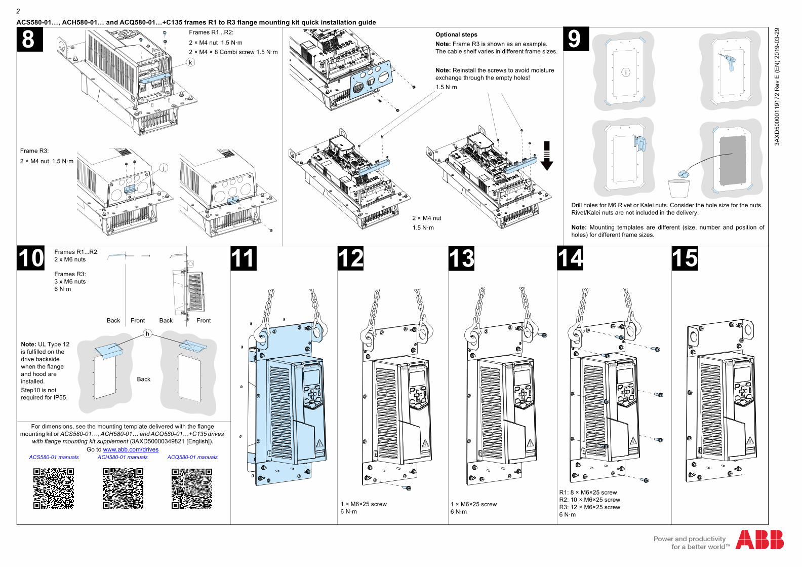
ACS580-01…, ACH580-01… and ACQ580-01…+C135 frames R1 to R3 flange mounting kit quick installation guide
k
For dimensions, see the mounting template delivered with the flange
mounting kit or ACS580-01…, ACH580-01… and ACQ580-01…+C135 drives with flange mounting kit supplement (3AXD50000349821 [English]).
Go to www.abb.com/drives ACS580-01 manuals ACH580-01 manuals ACQ580-01 manuals
Back
14
Drill holes for M6 Rivet or Kalei nuts. Consider the hole size for the nuts. Rivet/Kalei nuts are not included in the delivery.
Note: Mounting templates are different (size, number and position ofholes) for different frame sizes.
9
13
Optional stepsNote: Frame R3 is shown as an example. The cable shelf varies in different frame sizes.
Note: Reinstall the screws to avoid moisture exchange through the empty holes!1.5 N·m
1 × M6×25 screw6 N·m
1 × M6×25 screw6 N·m
R1: 8 × M6×25 screwR2: 10 × M6×25 screwR3: 12 × M6×25 screw6 N·m
15
i
Note: UL Type 12 is fulfilled on the drive backside when the flange and hood are installed. Step10 is not required for IP55.
h
8
jj
2 × M4 nut1.5 N·m
10 Frames R1...R2:2 x M6 nuts
Frames R3:3 x M6 nuts6 N·m
FrontBack Back Front
1211
Frame R3:
2 × M4 nut 1.5 N·m
Frames R1...R2:
2 × M4 nut 1.5 N·m2 × M4 × 8 Combi screw 1.5 N·m
3AXD
5000
0119
172
Rev
E (E
N) 2
019-
03-2
9