Embed Size (px)
Citation preview
0
ACR Manual on MR Safety
2020
ACR COMMITTEE ON MR SAFETY AMERICAN COLLEGE OF RADIOLOGY | 1891 Preston White Drive, Reston, VA 20191
1
ACR Manual on MR Safety
Version 1.0
2020
ACR Committee on MR Safety

2
CONTENTS ACKNOWLEDGMENTS .............................................................................................................. 3
Preface............................................................................................................................................. 4
Revisions ......................................................................................................................................... 5
Introduction ..................................................................................................................................... 6
Establishing, Implementing, and Maintaining Current MR Safety Policies and Procedures ......... 7
MR Personnel.................................................................................................................................. 7
MR Screening ................................................................................................................................. 9
Gowning ........................................................................................................................................ 14
Full stop/Final check ..................................................................................................................... 14
Special Patient Population Considerations ................................................................................... 15
MRI Contrast Agents .................................................................................................................... 18
MRI Patient Risk Assessment ....................................................................................................... 18
Physiologic Monitoring During MR Studies ................................................................................ 18
Implants, Devices, and Objects ..................................................................................................... 19
MR Environment .......................................................................................................................... 22
Static Magnetic Field-Related Issues ............................................................................................ 29
Time-Varying Gradient Magnetic Field–Related Issues .............................................................. 31
Time-Varying RF Magnetic Field–Related Issues ....................................................................... 32
References ..................................................................................................................................... 37
Appendix 1: Personnel Definitions and Organizational Structure ................................................ 43
Appendix 2: Magnetic Resonance Facility Safety Design Guidelines ......................................... 45
Appendix 3: MAgnetic Resonance Facility Emergency Preparedness Guidelines ...................... 53
3
ACKNOWLEDGMENTS Emanuel Kanal, MD, FACR University of Pittsburgh Medical Center, Pittsburgh
Todd Greenberg, MD, CSCS*D - Chair Private Practice, Seattle
Michael N. Hoff, PhD University of Washington, Seattle
Tobias B. Gilk RAD-Planning, Kansas City
Edward Jackson, PhD, FACR University of Wisconsin, Madison
Alexander M. McKinney, IV, MD University of Minnesota Medical Center, Minneapolis
Joseph Och, MS Geisinger, Danville
Ivan Pedrosa, MD, PhD University of Texas Southwestern Medical Center, Dallas
Tina Rampulla , RT WellSpan Health York Hospital, York
Scott B. Reeder, MD, PhD University of Wisconsin, Madison
Jeffrey Rogg, MD, FACR Alpert Medical School of Brown University, Providence
Frank G. Shellock, PhD, FACR University of Southern California, Los Angeles
Robert E. Watson, JR, MD Mayo Clinic, Rochester
Jeffrey C. Weinreb, MD, FACR Yale School of Medicine, New Haven
Although Dr. Emanuel Kanal was not a member of the ACR MR Safety Committee at the time this Manual was created, the ACR wishes to acknowledge that Dr. Kanal was the author and/or first author of the prior publications on which this Manual is based, and was also the primary contributor to the formulation of this MR Safety Manual.
Administration
Dina Hernandez American College of Radiology, Reston
Dustin Gress American College of Radiology, Reston
Mythreyi Chatfield American College of Radiology, Reston
4
PREFACE
The 2020 edition of the ACR Manual on MR Safety replaces all earlier versions. This document is published in a web-based format so that it can be revised and updated as needed.
In 2001, the American College of Radiology (ACR) formed a Blue-Ribbon Panel on Magnetic Resonance (MR) Safety in response to various reports in the medical literature and print media detailing MR imaging (MRI) adverse events and incidents involving patients, equipment, and personnel. Initially published in 2002, the ACR MR Safe Practices Guidelines established de facto industry standards for safe and responsible practices in clinical and research MR environments. Subsequently, these guidelines have been reviewed and updated throughout the years to address feedback from the field and installed base as well as changes in the MRI industry since the original publication. The ACR Manual on MR Safety represents the consensus of those representing the Committee on MR Safety of the ACR. The ACR Committee on MR Safety comprises professionals representing diverse fields and backgrounds that include research/academic radiologists, private-practice radiologists, MR/medical physicists, MR safety experts, patient safety experts/researchers, MR technologists, and others. It should be noted that these recommendations are not only appropriate from a scientific point of view but also reasonably applicable in the real world, with consideration given to patient care, throughput, financial pressures, and other considerations. The views expressed in this document are solely those of the authors and in no way imply a policy or position of any of the organizations represented by the authors.
This manual is copyright-protected and the property of the ACR. Any reproduction or attempt to sell this manual is strictly prohibited absent the express permission of the ACR.
5
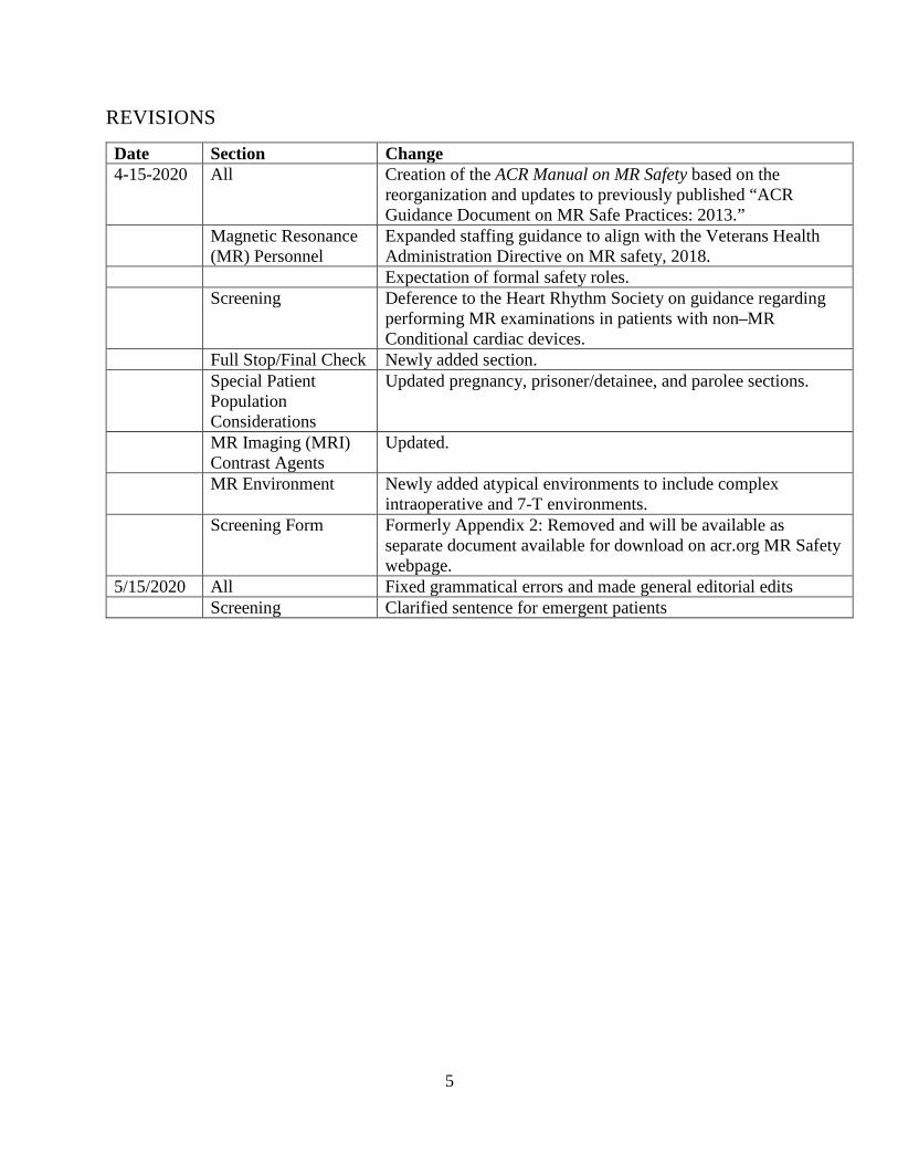
REVISIONS
Date Section Change 4-15-2020 All Creation of the ACR Manual on MR Safety based on the
reorganization and updates to previously published “ACR Guidance Document on MR Safe Practices: 2013.”
Magnetic Resonance (MR) Personnel
Expanded staffing guidance to align with the Veterans Health Administration Directive on MR safety, 2018.
Expectation of formal safety roles. Screening Deference to the Heart Rhythm Society on guidance regarding
performing MR examinations in patients with non–MR Conditional cardiac devices.
Full Stop/Final Check Newly added section. Special Patient
Population Considerations
Updated pregnancy, prisoner/detainee, and parolee sections.
MR Imaging (MRI) Contrast Agents
Updated.
MR Environment Newly added atypical environments to include complex intraoperative and 7-T environments.
Screening Form Formerly Appendix 2: Removed and will be available as separate document available for download on acr.org MR Safety webpage.
5/15/2020 All Fixed grammatical errors and made general editorial edits Screening Clarified sentence for emergent patients
6
INTRODUCTION
There are potential risks in the magnetic resonance (MR) environment, not only for the patient1,2 but also for the attending health care professionals, accompanying family members, and others, including security officers, housekeeping personnel, firefighters, police, etc, who may encounter the magnetic fields and other energy sources associated with MR scanners.3–6
The following ACR Manual on MR Safety is intended to be used as a template for MR facilities to follow in the development of a safety program. These guidelines were developed to help guide MR practitioners regarding these issues and to provide a basis for them to develop and implement their own MR policies and practices. These guidelines, along with the policies and procedures that are developed, are intended to be reviewed and updated annually.
The principles found in this safety manual are intended to apply to clinical diagnostic imaging, research, and atypical MR settings (eg, linear accelerator MR, interventional MR, etc) and encompass information for patients, research subjects, and health care personnel. It is worth noting that the use of remote MR system operation does not, in any way, diminish the obligations of the site to provide safe MR patient care.
The American College of Radiology (ACR) Committee on MR Safety supports the recommendations of the consensus document calling for formal MR safety roles and responsibilities for facility management of MR safety. These roles include MR Medical Director (MRMD), MR Safety Officer (MRSO), and MR Safety Expert (MRSE).7
Throughout this manual, the standard MR labeling terms (MR Safe, MR Conditional, and MR Unsafe) designated by the American Society for Testing Materials (ASTM) International, ASTM F2503-13 Standard Practice for Marking Medical Devices and Other Items for Safety in the MR Environment,8 are used.
Health care professionals need to recognize that one should never assume MR safety information related to an implant or device if it is not clearly documented in writing. Decisions based on published MR safety information should recognize that all safety claims regarding MR Conditional devices apply only to specifically tested conditions, such as the static magnetic field strength (B0), the strength of the static magnetic field gradient (dB/dx), the strength and duration of the transmitted radiofrequency (RF) energy (B1), and the rate of change of the time-varying imaging gradients (dB/dt).
Finally, there are many issues that impact MR safety that should be considered during site planning for a given MR installation. This document includes information in separate sections and appendices that address such issues, including cryogen emergency vent locations and pathways, the 5-G line, siting considerations, patient access pathways, and others. Despite their appearance herein, these issues, and many others, should be reviewed with those experienced with MR site planning and familiar with the patient safety and patient flow considerations prior to committing construction to a specific site design. In this regard, enlisting the assistance from an experienced architectural firm and doing so early in the design stage of the planning process will be beneficial.
7
It remains the intent of the ACR that this ACR Manual on MR Safety will prove helpful as the field of MR imaging (MRI) continues to evolve and mature, providing MR services that are not only safe but also valuable from a clinical or research point of view.
ESTABLISHING, IMPLEMENTING, AND MAINTAINING CURRENT MR SAFETY POLICIES AND PROCEDURES
All clinical and research MR facilities, irrespective of magnet format or field strength, including installations for diagnostic, research, interventional, and/or intra- or perioperative applications, should maintain MR safety policies.
These policies and procedures should be reviewed concurrently with the introduction of any substantial changes in safety parameters of the MR system or site (eg, related to hardware and/or software upgrades resulting in faster or stronger gradient capabilities or higher RF duty cycles) and updated as needed. During the review process, national and international standards and recommendations should be taken into consideration prior to establishing local guidelines, policies, and procedures.
Each MR facility will name a physician MRMD whose responsibilities will include ensuring that MR safe-practice guidelines are established and maintained as current and appropriate for the facility. The MR facility’s administrative staff must ensure that the policies and procedures that result from these MR safe-practice guidelines are implemented and adhered to at all times by all of the site’s personnel.
Procedures should be in place to ensure that all MR-related adverse events, safety incidents, or “near incidents” that occur are reported to the MRMD in a timely manner (eg, within 24 hours or 1 business day of their occurrence) and used in continuous quality improvement efforts. The US Food and Drug Administration (FDA) requests that MR facilities also report adverse events and incidents to them via their MedWatch program.9 The ACR Committee on MR Safety supports this recommendation and feels that it is in the best interest of MR practitioners to create and maintain this consolidated database of such events to help all of us learn about them and how to better avoid them in the future.10
MR PERSONNEL
MR Personnel and Non-MR Personnel
All individuals responsible for safety in Zones III or IV of the MR environment should be documented as having been successfully educated regarding MR safety issues (in a manner defined by the facility’s MRMD) at least to a level sufficient to ensure that they do not represent a danger to themselves or others in the MR environment. Such MR safety educational participation should be repeated annually, and appropriate documentation should be maintained to confirm this ongoing MR safety educational effort. These individuals will be referred to as MR Personnel. Note that that this level of training is more in depth and formal than that which might be provided to Non-MR Personnel, as described in the following paragraph.
8
Individuals who have not successfully attained this level of MR safety education will be referred to as Non-MR Personnel. Specifically, Non-MR Personnel will be the terminology used to refer to any individual who has not within the previous 12 months successfully undergone the designated formal MR safety education defined by the MRMD of that installation necessary to qualify as MR Personnel.
MR Technologists
MR technologists should comply with the technologist qualifications listed in the ACR MRI Accreditation Program requirements.11
MRI Safety Training Levels
There are 2 levels of MR Personnel, as described below.
Level 1 MR Personnel: Individuals who have passed the facility’s MR safety educational requirements (as defined by the facility’s MRMD) to ensure that they would not constitute a danger to themselves or others in the MR environment will henceforth be referred to as Level 1 MR Personnel (Appendix 1).
Level 2 MR Personnel: Those who have been more extensively trained and educated in the broader aspects of MR safety issues, including but not limited to issues related to the potential for RF-related thermal loading or burns and direct neuromuscular excitation from rapidly changing gradients, will henceforth be referred to as Level 2 MR Personnel.
Notably, it is the responsibility of the MRMD not only to identify the necessary training but also to identify those individuals who qualify as Level 1 and 2 MR Personnel (Appendix 1). Throughout this document, all references to MR Personnel that do not specify Level 1 or Level 2 will apply to both Level 1 and Level 2 MR Personnel.
Staffing
There will be a minimum of two MR technologists or one MR technologist and one other individual with the designation MR Personnel in the immediate Zone II through Zone IV MR environment whenever patients are in the MR environment. During this time, the two MR Personnel must be able to directly communicate within earshot of each other at all times. In all other ways, the ACR MR Safety Committee supports the Veterans Health Administration Responsibilities Directive 1105.05 for the Medical Facility Director of 2018:
Ensuring that when routinely scheduled patients or research subjects are present in Zones II through IV, there will be a minimum number of MR personnel in Zones III through IV to assure safe operation and adequate access control. The minimum number of MR personnel is calculated as follows:
(a) For a facility that functions with one MR machine per Zone III/IV, there will be a minimum of two MR personnel in Zones III through IV, and at least one of these personnel will be designated as Level 2 MR personnel. NOTE: Temporary exception is made when MR personnel are interviewing the patient/research subject or retrieving the patient/research subject from the waiting/changing areas.
9
(b) For a facility with two or more MR machines that share a single Zone III area where both machines are in use at the same time, there will be a minimum of one Level 2 MR Personnel for each machine and a minimum of one additional MR personnel, i.e., two machines during scheduled hours will require two Level 2 MR personnel and an additional Level 1 or 2 MR personnel. When only one machine is in use, e.g. during lunch or an evening shift, there will be a minimum of two MR personnel in Zones III through IV, and at least one of these personnel will be designated as Level 2 MR Personnel. NOTE: Facilities must prepare and plan to deal with emergencies that occur after normal business hours, e.g., fire, power outages, or water leaks, in the MR area.12
Supervision and Independent Access
Non-MR Personnel must be accompanied by, or under the immediate supervision of and in visual contact with, an individual from Level 2 MR Personnel throughout their stay in Zones III or IV, except in the changing room and/or bathroom, where verbal communication is sufficient.
Level 1 MR Personnel are permitted unaccompanied access throughout Zones III and IV. Level 1 MR Personnel are not permitted to directly admit, or to be responsible for, Non-MR Personnel in Zones III or IV.
No Level 2 MR Personnel shall relinquish their responsibility to supervise Non-MR Personnel in Zones III and/or IV until such supervision has been formally transferred to other Level 2 MR Personnel.
Formal MR Safety Roles
It is understood that the MRMD will have the necessary education and experience in MR safety to qualify as Level 2 MR Personnel. The MRMD, MRSOs, and MRSEs, as well as all MR Personnel, should undergo MR safety–specific education on an annual basis.7
MR SCREENING
All Non-MR Personnel needing to enter Zone III must first pass an MR safety screening process. Before Non-MR Personnel enter Zone III, final authorization must originate from Level 2 MR Personnel.
Nonemergent patients should be MR safety screened at least twice prior to being granted access to the MR environment. At least 1 of these screens should be performed by Level 2 MR Personnel verbally and/or interactively. For example, the patient (or their health care proxy) may complete a screening form and subsequently have the responses and contents of that form reviewed together with a Level 2 MR Technologist.
Emergent patients and their accompanying Non-MR Personnel may be screened only once, provided that the screening individual has Level 2 MR Personnel status. Any exceptions to this (such as but not limited to cases where a screening induced delay may result in imminent patient paralysis, blindness, and/or death) must be with the mutual agreement of the ordering physician

10
and covering Level 2 MR Physician, who specifically acknowledge the potential risks of a decision NOT to screen prior to granting that patient MR access.
The screening process and forms for patients, Non-MR Personnel, and MR Personnel should be essentially identical. Specifically, one should assume that screened Non-MR Personnel, health care practitioners, or MR Personnel might enter the bore of the MR system and be exposed to the static and/or time-varying magnetic fields at any time.
Examples of this include if a pediatric patient cries for his mother, who then leans into the bore of the scanner, or if an anesthesiologist leans into the bore to manually ventilate a patient in the event of a problem.
Careful screening for ferromagnetic materials by direct inspection and use of a ferromagnetic detector is recommended prior to entering Zone IV.13,14 MR Conditional devices may be ferrous, which can lead to activation of ferromagnetic detectors prior to entry into Zone IV. The manufacturers of ferromagnetic detectors today do not claim utility or sensitivity for screening of implants or foreign bodies within patients, although if sufficiently large and/or superficial, implant detection may be possible.15,16
Staff/Personnel Screening
All MR Personnel are to undergo an MR screening process as part of their employment agreement to ensure their safety in the MR environment. For their own protection and for the protection of the Non-MR Personnel under their supervision, all MR Personnel must immediately report to the MRMD any trauma, procedure, or surgery they experience or undergo where a ferromagnetic object or device may have become introduced within or on them. This will permit appropriate screening of the employee to determine the safety of permitting that employee into Zones III and/or IV.
Patient Screening
Conscious, nonemergent patients: Conscious, nonemergent patients and research and volunteer subjects are to complete written MR safety screening questionnaires prior to their introduction to Zone III. These completed MR safety screening questionnaires are then to be orally reviewed in their entirety with the patient, guardian, or research subject prior to permitting the individual clearance into Zone III.
The patient, guardian, or research subject and the screening MR staff member must both sign the completed form. This form should then become part of the individual’s medical record. No empty responses are accepted, and each question must be answered with a yes or no, or specific further information must be provided as requested. A sample pre–MR screening form is provided on the ACR.org MR Safety webpage, found at https://www.acr.org/Clinical-Resources/Radiology-Safety/MR-Safety . This is the minimum information to be obtained. Additional information may be added at the discretion of the facility.
Nonambulatory patients: MR scanning of hospitalized, higher-risk, or nonambulatory patients presents additional challenges. In many instances, these patients are too sick to enter Zone IV by themselves and must be transported into the MR scanner using an MR Conditional wheelchair or
11
stretcher. Similarly, metallic objects used for patient care (eg, needles, small oxygen tanks, etc) may be inadvertently transported after being used at other locations in the facility and hidden around the patient (ie, within sheets or pillow covers). When possible, transfer of these patients to the MR table should be done in Zone III (eg, via a detachable MR table).
Unconscious, unresponsive, altered-level-of-consciousness patients: When screening patients for whom an MR examination is deemed clinically indicated or necessary but who are unconscious or unresponsive; who cannot provide their own reliable histories regarding possible prior surgery, trauma, or injury by a metallic foreign body; or for whom such histories cannot be reliably obtained from others, the following steps should be taken.
a. Family members or guardians of such patients should complete a written MR safety screening questionnaire prior to the patient’s introduction to Zone III.
b. If no reliable patient history can be obtained, and if the requested MR examination cannot reasonably wait until a reliable history might be obtained, it is recommended that such patients undergo plain-film radiography (if recently obtained plain films, computed tomography [CT] studies, or MR studies of the following areas are not already available) to exclude potentially harmful embedded or implanted metallic foreign bodies, implants, or devices. Plain-film radiography should include the head/neck, chest, abdomen/pelvis, and upper arms and thighs. If there are obvious post-traumatic changes to the distal extremities, those regions should also undergo plain-film radiography prior to MR exposure.
Pediatric/minor patients: Children may not be reliable historians and, especially for older children and teenagers, should be questioned twice by Level 2 Personnel: once in the presence of parents or guardians and once separately to maximize the possibility that all potential dangers are disclosed. Therefore, it is recommended that they be gowned before entering Zone IV to help ensure that no metallic objects, toys, or other unacceptable items inadvertently find their way into Zone IV. Pillows, stuffed animals, and other comfort items brought from home represent potential risks and should be discouraged from entering Zone IV.
Companions in Zones III or IV: Those deemed appropriate to accompany or remain with the patient should be screened using the same criteria as anyone else entering Zone IV.
In general, it would be prudent to limit accompanying companions to a single individual. Only a qualified, responsible Level 2 MR Physician should make screening criteria exceptions.
Hearing protection and MR Safe/MR Conditional seating are recommended for accompanying companions within the MR scan room.
If an individual with Non-MR Personnel status who wishes to accompany a patient into an MRI system room (ie, Zone IV) requires screening for a possible orbital foreign body (ie, using x-rays or CT), an individual from Level 2 MR Personnel or a Level 2 MR Physician must first discuss with them the requirement for such screening prior to permitting them access to the MRI system room. Should the Non-MR Personnel individual still wish to proceed to Zone IV or past the 5-G line, and should a Level 2 MR Physician deem it medically advisable that they do so (eg, for the care of their child about to undergo an MRI examination), written informed consent should be
12
provided to the Non-MR Personnel individual prior to undergoing radiographic screening (ie, using x-rays or CT) of their orbits.
Screening Form/Risk Identification
Ferromagnetic detectors: The use of conventional metal detectors in the MR environments that do not differentiate between ferrous and nonferromagnetic materials is not recommended. The use of ferromagnetic detection systems (FMDSs) is recommended as an adjunct to thorough and conscientious screening of persons and devices prior to being permitted into Zone IV. The use of FDMSs is considered a supplement to and not a replacement for a thorough screening practice.
History of ferromagnetic foreign body penetration: All patients and Non-MR Personnel with a history of injury or implantation associated with a ferromagnetic foreign body or implant must undergo further investigation prior to being permitted entry to Zone III. Examples of acceptable methods of screening include patient history, plain x-ray films, prior CT or recent MR studies of the anatomic area in question, or access to written documentation as to the type of implant or foreign object that might be present. Once positive identification has been made as to the type of implant or foreign object that is within the patient, best-effort assessments should be made to identify the conditions for MR safety of the implant or object. Efforts at positive identification include written records of the results of formal testing of the implant prior to implantation, product labeling regarding the implant or object, and peer-reviewed publications regarding the conditions of MR safety of the specific make, model, and type of implant. MR safety testing would be of value only if the object or device had not been altered since publication of such testing results and only if it can be confirmed that the testing was performed on an implant or object of precisely the same make, model, and type.
History of orbital trauma: All patients with a history of orbital trauma by a potential ferromagnetic foreign body for which they sought medical attention are to have their orbits cleared either by plain x-ray orbit films17,18 or by a radiologist's review and assessment of prior CT or MR images (obtained since the suspected traumatic event), if available. An evaluation of a prior MRI examination’s susceptibility artifact of the region of the orbits may provide an experienced reader with important information on the ferromagnetic nature of the foreign body.
Implanted/onplanted devices: All Non-MR Personnel with implanted cardiac pacemakers, implantable cardioverter defibrillators (ICDs), diaphragmatic pacemakers, medication pumps, cochlear implants, or other electromechanically activated devices on which the Non-MR Personnel are dependent should be precluded from entering Zone IV and prevented from passing the 5-G line unless specifically cleared in writing by a Level 2 MR Physician or the MRMD of the MR facility. In such circumstances, specifics defending the risk-benefit rationale should be provided in writing and signed by the Level 2 MR Physician.
Intracranial aneurysm clips: If it is unclear whether a patient has an implanted intracranial aneurysm clip, plain films should be obtained. Alternatively, if available, recent cranial plain films or CT or MR examinations should be reviewed to assess for a possible intracranial aneurysm clip.
13
In the event that a patient is identified to have an intracranial aneurysm clip, the MR examination should not be performed until it can be documented that the specific manufacturer, model, and type of aneurysm clip within that patient are MR Conditional. All documentation of types of implanted clips, dates, etc, must be in writing and signed by a licensed physician. Phone, verbal histories, and/or histories provided by a nonphysician are not acceptable. Electronic copies of operative reports, physician statements, etc, are acceptable as long as a legible physician signature accompanies the requisite documentation. A written history of the clip describing appropriate testing for ferromagnetic properties (and description of the testing methodology used) prior to implantation by the operating surgeon is also considered acceptable if the testing follows the standard test methods established by ASTM International.
All intracranial aneurysm clips manufactured in 1995 or later for which the manufacturer’s product labeling continues to claim MR Conditional status may be accepted for MR scanning under the specified conditions without further testing. Implantation date, absent product manufacturing date information, is not sufficient to make a determination of acceptability for MR scanning without further testing.
Clips manufactured prior to 1995 require either pretesting (as per the ASTM International F2503 Standard Practice guidelines)8 prior to implantation or individual review of previous MRI of the clip or brain in that particular case, if available. By assessing the size of the artifact associated with the clip relative to the static field strength on which it was studied, the MRI pulse sequence type, and the MRI parameters selected, an opinion may be issued by one of the facility’s Level 2 MR Physicians as to whether or not the clip demonstrates significant ferromagnetic properties. Access to the MR scanner would then be based on that opinion.
A patient with an aneurysm clip (or another implant) may have safely undergone a prior MR examination at any given static magnetic field strength. This fact is insufficient evidence of the implant’s safety and should not be relied on to determine the MR safety status of that aneurysm clip (or other implant) for future MR examinations.
Variations in static magnetic field strength, static magnetic field gradient, orientation of the aneurysm clip (or other implant) relative to the static magnetic field or its static magnetic field gradient, and rate of motion through that static magnetic field gradient, as well as other factors, are variables that are impossible to control or reproduce. These variables may not have resulted in an adverse event in one circumstance but may result in significant injury or death on a subsequent MR exposure. For example, a patient who went blind from interactions between the metallic foreign body in his retina and the static magnetic field of the MR system entered the scanner and underwent the entire MR examination without difficulty. This patient only went blind on exiting the MR system at the completion of the examination.19
Barring the availability of either pretesting or prior MRI-related data for the aneurysm clip in question, the supervising physician in each case must perform a risk-benefit assessment and review. Furthermore, for patients with intracranial aneurysm clips with no available ferromagnetic or imaging data, should the risk-benefit ratio favor the performance of the MR examination, the patient or guardian should provide written informed consent that includes death as a potential risk of the MR procedure prior to permitting that patient to undergo an MR
14
examination. Because research scans in general do not offer benefit for the research subject, scanning patients without written information about the specific device is strongly discouraged.
Pacemakers/ICDs: Cardiac implantable electronic devices (CIEDs) have expanded in number and complexity since their introduction in 1958 and now include cardiac pacemakers, ICDs, cardiac resynchronization therapy (CRT) devices, implantable cardiovascular monitors (ICMs), and implantable loop recorders (ILRs). Cardiac pacemakers, which include implantable pulse generators (IPGs) and leads that are approved by the FDA and are labeled MR Conditional, became available in the United States in 2011. Since then, other commercially available CIEDs have been labeled MR Conditional, including ICDs, CRT devices, ILRs, and ICMs. Product instructions for use on wallet patient identification cards, manufacturer-maintained databases, lead and IPG identifiers visualized on plain films, and operative notes may assist in the proper identification of MR Conditional CIEDs.
Guidance regarding performing MR examinations in patients with non–MR Conditional cardiac devices, including cardiac pacemakers, ICDs, CRT devices, ILRs, and ICMs, is deferred to current recommendations from the Heart Rhythm Society.20
Previous experiences with MRI in patients who have retained metallic materials after cardiac surgery, such as epicardial pacing leads, may be helpful.21 Although some have produced survey data suggesting that in the case of postoperatively retained cardiac pacing wires, “the absence of reported complications in thousands of exposed patients suggests that the risk is low,”22 others have voiced appropriate concern as to the general relevance of these data to the overall population.23
GOWNING
Any individual undergoing an MR procedure must remove all readily removable metallic personal belongings and devices on or in them. This includes the removal of watches, jewelry, pagers, cell phones, body piercings, contraceptive diaphragms, metallic drug-delivery patches, cosmetics containing metallic particles (such as eye makeup or magnetic eyelashes), and clothing items that may contain metallic fasteners, hooks, zippers, or loose metallic components/threads or have been treated with antimicrobial electrically conductive materials. Therefore, it is advisable to require that the patients or research subjects wear site-supplied MR Safe scrubs or gowns in place of their own clothing and undergarments in the region undergoing direct RF irradiation (see thermal considerations below).
FULL STOP/FINAL CHECK
A “full stop and final check” performed by the MRI technologist is recommended to confirm the satisfactory completion of MR safety screening for the patient, support equipment, and personnel immediately prior to crossing from Zone III to Zone IV. The purpose of this final check is to confirm the patient’s identification, ensure that all screening has been appropriately performed, and ensure that there has been no change in patient and/or equipment status while in Zone III.
15
SPECIAL PATIENT POPULATION CONSIDERATIONS
Pregnancy
Health care practitioner pregnancies: Pregnant health care practitioners are permitted to work in and around the MR environment throughout all stages of their pregnancy.24 Acceptable activities include, but are not limited to, positioning patients, scanning, archiving, injecting contrast, and entering the MR system room in response to an emergency. Although permitted to work in and around the MR environment, pregnant health care practitioners are requested not to remain within the MR scanner bore or Zone IV during actual data acquisition or scanning. These recommendations are based on the preponderance of data on 3 T magnetic fields. There is a paucity of data available to date regarding human pregnancy exposures to 7 T magnetic fields.
Patient pregnancies: The vast majority of data today has failed to show that exposure to MR has deleterious effects on the developing fetus. Nevertheless, if pregnancy is established, the decision to proceed with a noncontrast MR study at 1.5 T should be based on the medical benefits weighed against unknown potential risk.
The safety of MRI at field strengths higher than 1.5 T (ie, 3 T, 7 T) during pregnancy has not been thoroughly assessed. However, the preponderance of research studies has failed to discover any reproducible harmful effects of exposure of the mother or developing fetus to the 3 T or weaker magnetic fields used in the routine clinical MRI process.25 Theoretical concerns include time-varying gradient and RF magnetic fields, potential acoustically related safety issues, and heat deposition in tissue, respectively. There is not much peer-reviewed literature regarding the acoustic safety of fetal scanning, but the majority of published material on this topic has failed to find deleterious effects on newborn hearing if exposed to MRI in utero.26–30 The thermally related theoretical concerns are mitigated by results from experiments in pregnant pigs exposed to standard MR sequences commonly used in clinical practice that are associated with relatively high specific absorption rate (SAR) levels (ie, half-Fourier single-shot spin echo). Such studies failed to demonstrate substantial heating in fetal tissues or amniotic fluid when imaging at 3 T with normal-operating-mode SAR levels and a maximum scan time of 30 minutes.31,32 Therefore, 3 T MR examinations performed within normal operating mode for durations less than 30 minutes should be considered safe in pregnant patients. Ultimately, the decision to image a pregnant patient at 3 T should be based on local institutional policies, medical needs, and accessibility to 1.5 T versus 3 T MR scanners. At this point, the safety of imaging pregnant patients at field strengths greater than 3 T (ie, 7 T) is unclear.
MR contrast agents should not be routinely administered to pregnant patients.33 Indeed, there is widespread consensus that avoiding gadolinium-based contrast agents (GBCAs) in pregnancy is prudent.33 This decision is typically made according to the institutional contrast policy, on a case-by-case basis, by the attending radiologist or designated radiology provider (eg, radiology resident, fellow), who can assess the risk-benefit ratio for that particular patient.
The decision to administer an MR GBCA to pregnant patients should be accompanied by a well-documented and thoughtful risk-benefit analysis. This analysis should be able to defend a decision to administer the contrast agent based on overwhelming potential benefit to the patient
16
or fetus outweighing the potential but unclear or unknown risks of exposure of the developing fetus to GBCAs.
Studies have demonstrated that at least some of the MR GBCAs readily pass through the placental barrier and enter the fetal circulation in nonhuman primates.34,35 Although the amount of gadolinium present in the fetoplacental circulation was at much lower quantities than in the mother, their biodistribution was comparable to that expected in an adult.34 The highest concentration of the injected dose of MR GBCAs in these experiments was found in the fetal kidney.34 From here, they are filtered and then excreted into the amniotic fluid. In this location, the gadolinium-chelate molecules are in a relatively protected space and may remain for some time before finally being reabsorbed and eliminated. A significant decrease was found in the amniotic fluid’s gadolinium-chelate concentration 45 hours after administration relative to that in the 19- to 21-hour period in nonhuman primates.34 Moreover, a study in mice reported undetectable fetal concentrations 48 hours after administration of an extracellular GBCA.35
A recent publication highlighted an increased exposure level of first-trimester pregnancies to gadolinium, suggesting that increased screening and vigilance may be warranted when administering GBCAs to potentially pregnant patient populations.36
Pediatric MR Safety Concerns
Sedation and monitoring issues: Children form the largest group requiring sedation for MRI. Sedation may not always be required: for example, if an ultrafast MR examination may be diagnostic. When necessary, sedation protocols may vary from institution to institution according to procedures performed (diagnostic vs interventional), the complexity of the patient population (healthy preschoolers vs premature infants), the method of sedation (mild sedation vs general anesthesia), and the qualifications of the sedation provider.
Adherence to standards of care mandates following the sedation guidelines developed by the American Academy of Pediatrics,37 the American Society of Anesthesiologists,38 and The Joint Commission (TJC).39 In addition, sedation providers must comply with protocols established by the individual state and the practicing institution. These guidelines require the following provisions:
a. preprocedural medical history and examination for each patient, b. fasting guidelines appropriate for age, c. uniform training and credentialing for sedation providers, d. intraprocedural and postprocedural monitors with adaptors appropriately sized for
children (MR Conditional equipment), e. method of patient observation (window, camera), f. resuscitation equipment, including oxygen delivery and suction, g. uniform system of record keeping and charting (with continuous assessment and
recording of vital signs), h. location and protocol for recovery and discharge, and i. quality assurance program that tracks complications and morbidity.
17
For the neonatal and the young pediatric population, special attention is needed in monitoring body temperature for both hypo- and hyperthermia, in addition to other vital signs. Temperature monitoring equipment that is approved for use in the MR suite is readily available. Commercially available, neonatal isolation transport units and other warming devices intended to be used in the MR environment are also available.
Claustrophobia, Anxiety, and Sedation
Adult and pediatric patient anxiolysis, sedation, analgesia, and anesthesia for any reason should follow established ACR,40 American Society of Anesthesiologists,41–43 and TJC standards.39 Implementation of standard operating procedures and policies for management of claustrophobic/anxious patients is recommended.
Prisoners/Detainees
MR scanning of patients who are incarcerated present unique MR safety challenges. These patients may present wearing ferromagnetic shackles and are accompanied by correctional officers who may be carrying ferromagnetic objects and weapons. Prior to the patient arriving to the MR department, notification to the corrections department for an alternative nonferrous restraining option should be requested. MR screening of the patient and the accompanying correctional officer(s) shall take place prior to entering Zone III. The accompanying officer(s) should be educated as to the static magnetic field safety issues and, if they agree, should accompany the technologist into Zone IV for patient positioning and retrieval. Ferromagnetic weapons should not be permitted into Zone III unless deemed absolutely essential for maintenance of security. Note that firearms with ferromagnetic components pose a potential serious threat in Zone IV (the MR system room).44,45
Any accompanying officer carrying a firearm should be instructed to refrain from entering Zone IV, as firearms represent potential projectiles and are a potential hazard to all if brought into Zone IV.44,45
Parolees
Situations wherein patients who are on parole wearing metallic prisoner-restraining devices such as RF identification or tracking bracelets could theoretically lead to adverse events, including (1) ferromagnetic attractive effects leading to patient injury, (2) ferromagnetic attractive effects leading to device/battery pack damage, (3) RF interference with the MRI study and secondary image artifact, (4) RF interference with the functionality of the device, and (5) RF power deposition leading to heating of the bracelet, tagging device, or its circuitry, and secondary patient injury (if the bracelet would be in the volume of the RF transmitter coil being used for imaging). Therefore, in cases in which a patient wearing RF bracelets, metallic handcuffs, or ankle cuffs needs an MR examination, a request should be made that the patient be accompanied by the appropriate authorities who can and will remove the restraining device prior to the MR study and be charged with its replacement following the examination.
18
MRI CONTRAST AGENTS
No patient is to be administered prescription MR contrast agents without orders from a duly licensed physician. Intravenous (IV) injection–qualified MR Personnel may establish and attend to peripheral IV access lines if they have undergone the requisite site-specified training in peripheral IV access and have demonstrated and documented appropriate proficiency in this area. IV injection–qualified MR Personnel may administer FDA-approved MR GBCAs via peripheral IV routes as a bolus or slow or continuous injection as directed by the orders of a duly licensed site physician.
Practices relating to administration of these agents and recommendations regarding GBCA usage, adverse reactions, nephrogenic systemic fibrosis, and retained or residual gadolinium should follow the ACR Committee on Drugs and Contrast Media. The most recent version of the ACR Manual on Contrast Media may be downloaded from the ACR website at https://www.acr.org/Clinical-Resources/Contrast-Manual.
MRI PATIENT RISK ASSESSMENT
Final determination of whether or not to scan a patient is to be made by the Level 2 MR Physician responsible for the patient, or the MRMD. Potential risks of proceeding with the requested MR imaging examination may include, among others, patient positioning; contrast reactions; consideration of mechanical, thermal, and functional risks associated with MRI of implants; and assessments of the safety of exposure of the device to the electromagnetic forces used in the MRI process.
PHYSIOLOGIC MONITORING DURING MR STUDIES
Using physiological monitoring for patients during MR examinations is often necessary. However, monitoring techniques should be carefully selected primarily because of the risk of thermal injury associated with monitoring equipment in the MR environment. While not all RF-induced thermal injuries can be detected as they are developing, sedated, anesthetized, or unconscious patients are especially vulnereable to such injuries as they are never able to provide the operator with adequate warning of actively developing thermal injuries. This potential for injury is greater on higher-field-strength MR scanners (eg, 1 T and above) but exists, at least theoretically, at all MRI field strengths. MR Conditional electrocardiogram (EKG) electrodes should be used and leads should be positioned per the EKG manufacturer’s direction during the scan.
Distortion of the EKG within the magnetic field can make interpretation of the EKG complex unreliable, even with filtering used by contemporary monitoring systems.
Routine monitoring of the patient’s heart rate and rhythm may also be accomplished using pulse oximetry. Use of an MR Conditional pulse oximeter can address the risks of thermal injury if MR conditions are followed and/or the device and its leads are entirely positioned outside of the volume undergoing exposure to the transmitted RF energy.
19
IMPLANTS, DEVICES, AND OBJECTS
When a patient is in the MR scanner’s bore, if reasonable care allows, no Non-MR Personnel or materials that are not required for the care of that patient should enter Zone IV until the patient has been removed fully from the scanner.
Ferrous objects, including those brought by patients, visitors, contractors, etc, should be restricted from entering Zone III whenever practical.
As part of the Zone III site restriction and equipment testing and clearing responsibilities, all sites should have ready access to a strong handheld magnet (>1000 G) and/or a ferromagnetic detection device. This will enable the site to test external, and even some superficial internal, devices or implants for the presence of grossly detectable ferromagnetic attractive forces.
a. All portable metallic or partially metallic devices that are on or external to the patient (eg, oxygen cylinders) are to be positively identified in writing as MR Unsafe or MR Conditional in the MR environment prior to permitting them into Zone III. For all device or object screening, verification and positive identification should be in writing. Examples of devices that need to be positively identified include fire extinguishers and oxygen tanks.
b. External devices or objects demonstrated to be ferromagnetic and MR Unsafe in the MR environment may be brought into Zone III under specific circumstances if, for example, they are deemed by MR Personnel to be necessary and appropriate for patient care. They should only be brought into Zone III if they are under the direct supervision of specifically designated MR Personnel who are thoroughly familiar with the device, its function, and the reason supporting its introduction to Zone III. The safe use of these devices while they are present in Zone III will be the responsibility of specifically named MR Personnel. These devices must be appropriately physically secured or restricted at all times within Zone III to ensure that they do not inadvertently come too close to the MR scanner and accidentally become exposed to static magnetic fields or gradients that might result in their becoming either hazardous projectiles or no longer accurately functional.
c. Never assume an MR Conditional or MR Safe status of a device if it is not clearly documented in writing. All unknown external objects or devices being considered for introduction beyond Zone II should be tested with a strong handheld magnet (>1000 G) and/or a ferromagnetic detection device for ferromagnetic properties prior to permitting them entry to Zone III. The results of such testing, as well as the date, time, name of the tester, and methodology used for that particular device, should be documented in writing. If a device has not been tested, or if its MR safety status is unknown, it should not be permitted unrestricted access into Zone III.
d. All portable metallic or partially metallic objects that are to be brought into Zone IV must be properly identified and appropriately labeled using the current FDA labeling criteria developed by ASTM International in ASTM Standard F2503.8 Those items that are wholly nonmetallic and not electrically conductive should be identified with a square green MR Safe label. Items that are clearly ferromagnetic should be identified as MR
20
Unsafe and labeled appropriately with the corresponding round red label. Objects with an MR Conditional status should be affixed with a triangular yellow MR Conditional label prior to being brought into the scan room/Zone IV.
e. It should be noted that alterations performed by the facility on MR Safe, MR Unsafe, and MR Conditional equipment or devices may alter the MR safety or compatibility properties of the device. For example, tying a ferromagnetic metallic twisting wire/binder onto a sign labeling the device as MR Conditional or MR Safe might result in image artifacts and/or safety issues if introduced into the MR scanner.
As noted above, if MR safety data are not prospectively available for electrically active equipment or objects, they should not be brought into Zone IV without being subjected to the testing outlined in ASTM International Standard F2503. If MR safety data are not prospectively available for a given object that is not electrically activated (eg, wash basins, scrub brushes, step stools), initial testing for the purpose of this labeling is to be accomplished by the facility’s MR Personnel exposing the object to a handheld magnet (>1000 G) or ferromagnetic detector. If grossly detectable ferromagnetic properties are observed, it is to be labeled with a circular red MR Unsafe label. If none are observed, a triangular yellow MR Conditional label is to be attached to the object. It is only when the composition of an object and its components are known to be nonmetallic and not electrically conductive that the green MR Safe label is to be affixed to a device or object.
Classifications
Particularly with regard to nonclinical and incidental equipment, current products marketed with ill-defined terminology such as nonmagnetic or outdated classifications such as MR compatible should not be presumed to conform to a particular current ASTM International classification. Similarly, any product marketed as MR Safe but with metallic construction or components should be treated with suspicion. Objects intended for use in Zone IV, including nonclinical incidental products such as stepping stools or ladders, which are not accompanied by manufacturer or third-party MR safety test results under the ASTM International Standard F2503 criteria, should be site-tested as described above.
21
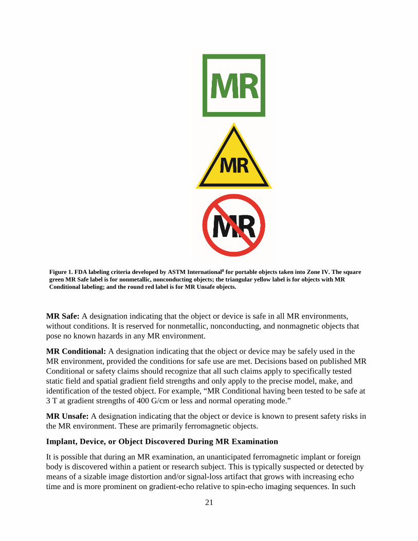
Figure 1. FDA labeling criteria developed by ASTM International8 for portable objects taken into Zone IV. The square green MR Safe label is for nonmetallic, nonconducting objects; the triangular yellow label is for objects with MR Conditional labeling; and the round red label is for MR Unsafe objects.
MR Safe: A designation indicating that the object or device is safe in all MR environments, without conditions. It is reserved for nonmetallic, nonconducting, and nonmagnetic objects that pose no known hazards in any MR environment.
MR Conditional: A designation indicating that the object or device may be safely used in the MR environment, provided the conditions for safe use are met. Decisions based on published MR Conditional or safety claims should recognize that all such claims apply to specifically tested static field and spatial gradient field strengths and only apply to the precise model, make, and identification of the tested object. For example, “MR Conditional having been tested to be safe at 3 T at gradient strengths of 400 G/cm or less and normal operating mode.”
MR Unsafe: A designation indicating that the object or device is known to present safety risks in the MR environment. These are primarily ferromagnetic objects.
Implant, Device, or Object Discovered During MR Examination
It is possible that during an MR examination, an unanticipated ferromagnetic implant or foreign body is discovered within a patient or research subject. This is typically suspected or detected by means of a sizable image distortion and/or signal-loss artifact that grows with increasing echo time and is more prominent on gradient-echo relative to spin-echo imaging sequences. In such
22
cases, it is imperative that further image acquisition is put on hold and that the MRMD and/or Level 2 MR Physician responsible for the patient be immediately notified of the suspected findings. This individual should then assess the situation, review the imaging information obtained, and decide what the best course of action might be.
It should be noted that there are numerous potentially acceptable courses that might be recommended that are dependent on many factors, including the status of the patient, the location of the suspected ferromagnetic implant/foreign body relative to local anatomic structures, the mass of the implant, and other factors. Appropriate courses of action might include proceeding with the scan underway, immobilizing and immediately removing the patient from the scanner, or other intermediate steps. Regardless of the course of action selected, it is important to note that the forces on the implant will change, and may actually increase, during the attempt to remove the patient from the scanner bore. Further, the greater the rate of motion of the patient/device through the magnetic field near the scanner bore, the greater the forces acting on that device will likely be. Thus, it is prudent to ensure, if at all possible, that immobilizing the device during patient extraction from the bore, and employing a slow, cautious, deliberate rate of extricating the patient from the bore, will likely result in weaker and potentially less harmful forces on the device as it traverses the static magnetic field gradient associated with the MR scanner. See below for further discussion regarding MR-related forces.
The magnetic fields associated with the MR scanner are 3-dimensional. Thus, especially for superconducting systems, one should avoid the temptation to have the patient sit up as soon as they are physically out of the bore. Doing so may expose the ferrous object to significant torque- and translation-related forces despite their being physically outside the scanner bore. It is therefore advisable to continue to extract the patient along a straight line course parallel to the center of the magnet while the patient remains immobilized until they are as far as physically possible from the MR scanner itself before any other patient/object motion vector is attempted or permitted.
Should an implanted device inadvertently be exposed to any level of the energies associated with the MR system, the physician responsible for the maintenance of the active device(s) should be contacted prior to the patient’s discharge from the MRI suite. Significant injuries have resulted from such partial exposures, and adequate functionality should be verified and never assumed for critical devices.
MR ENVIRONMENT
Zones
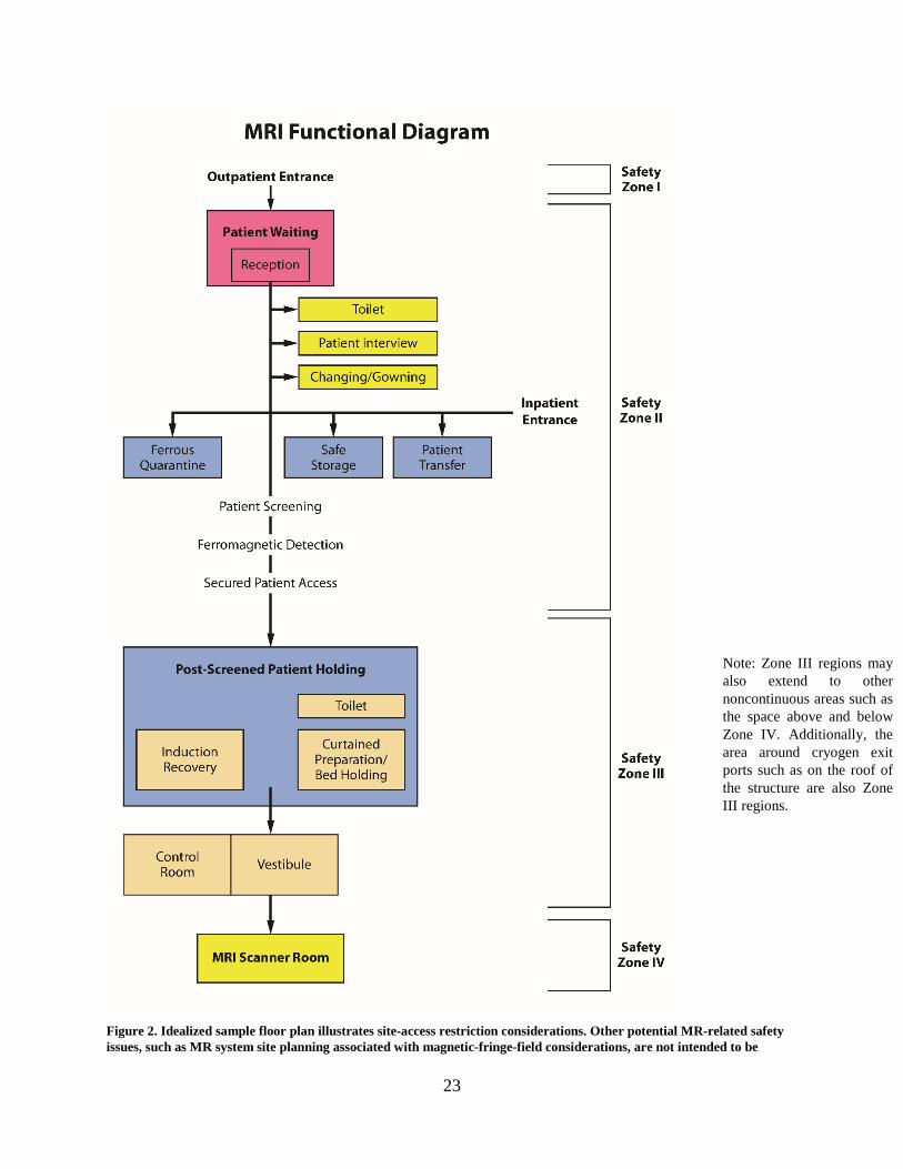
The MR facility may be conceptually divided into four zones (see Figure 2 and Appendices 2 and 3).
23
Figure 2. Idealized sample floor plan illustrates site-access restriction considerations. Other potential MR-related safety issues, such as MR system site planning associated with magnetic-fringe-field considerations, are not intended to be
Note: Zone III regions may also extend to other noncontinuous areas such as the space above and below Zone IV. Additionally, the area around cryogen exit ports such as on the roof of the structure are also Zone III regions.
24
included herein. Note: In any zone of the facility, there should be compliance with Health Insurance Portability and Accountability Act regulations in regard to privacy of patient information. However, in Zone III, there should be a privacy barrier so that unauthorized persons cannot view control panels.
Zone I: This region includes all areas that are freely accessible to the general public. This area is typically outside the MR environment itself and is the area through which patients, health care personnel, and other employees of the MR facility access the MR environment.
Zone II: This area is the interface between the publicly accessible, uncontrolled Zone I and the strictly controlled areas of Zones III and IV. Typically, patients are greeted in Zone II and are permitted to move freely throughout Zone II, under the supervision of MR Personnel, prior to entry into Zone III. It is recommended that patient preparation for the MRI examination take place in Zone II. This preparation includes MRI screening, medical history, and appropriate patient gowning.
Zone III: This area is the region in which free access by unscreened Non-MR Personnel or ferromagnetic objects and equipment can result in serious injury or death due to interactions between the individuals or equipment and the MR scanner's particular environment. Access by Non-MR Personnel to and supervision over Zone III (including Zone IV; see below) is controlled by, and entirely under the supervision of, Level 2 MR Personnel. Non-MR Personnel must be accompanied by, or under the immediate supervision of and in visual contact with, an individual who is of Level 2 MR Personnel status throughout their stay in Zones III or IV, except in the changing room and/or bathroom, where verbal communication is sufficient. To avoid misunderstandings or questions of responsibility, each Non-MR Personnel individual entering Zone III must have a specifically identified Level 2 MR Personnel individual (typically—but not necessarily—an MR technologist) responsible for them throughout their stay in Zone III. This function of the Level 2 MR Personnel is directly under the authority and responsibility of the MRMD or the Level 2 MR Physician of the day for the MR facility.
Zone III regions should be physically restricted from general public access by key locks, passkey locking systems, or any other reliable, physically restricting method that can differentiate between MR Personnel and Non-MR Personnel. The use of combination locks is discouraged because combinations often become more widely distributed than initially intended, resulting in the possibility of a facility restriction violation. Only MR Personnel should be provided free access, via methods such as the access keys or passkeys, to Zone III.
There should be no exceptions to this guideline. Specifically, this includes hospital or facility administrative staff, physicians, security personnel, and other Non-MR Personnel. Zone III should be demarcated and clearly indicated as being potentially hazardous.
Among the energies that render the MR environment potentially harmful are static magnetic fields. Being 3-dimensional, Zone III controlled-access areas may project not just around but also above and below the room housing the MR scanner. This imposes a potential magnetic field hazard on individuals on floors other than that on which the scanner is found. Similarly, the typical rooftop cryogen vent location is associated with potential hazards during an active quench (loss of superconductivity/magnetic field), and access to that vent is a Zone III region. These Zone III potentially harmful access areas should be clearly identified, and their potential hazard should be clearly marked, even in typically unoccupied areas such as rooftops or storage
25
rooms. For this reason, magnetic-field-strength spatial plots for all MRI systems should be analyzed in both horizontal and vertical orientations, identifying areas around, above, and/or below the scanner, which may pose potential hazards, and quench vent pathways should also be considered when defining Zone III regions.
Zone IV: This area is synonymous with the MR scanner room itself (ie, the physical confines of the room where the scanner is located). Zone IV, by definition, will always be located within Zone III, as it is the MR magnet and its cryostat that generate the existence of Zone III. Zone IV should also be clearly labeled as being potentially hazardous because of the presence of very strong magnetic fields. As part of the Zone IV site restriction, all MR installations should provide for visual observation by Level 2 MR Personnel to access pathways into Zone IV. By means of illustration only, the MR technologists would be able to directly observe and control, via line of sight or via video monitors, the entrances or access corridors to Zone IV from their normal positions when stationed at their desks in the scan control room. Importantly, controlled site-access restriction to Zones III and IV must be maintained during resuscitation and other emergent situations for the protection of all involved.
The entrance to Zone IV should be clearly marked with a prominently displayed red illuminated sign stating “The Magnet is Always On,” except for in the case of resistive MR systems, which should have a red illuminated sign stating “The Magnet is On” when it is energized. Ideally, signage should inform the public that the magnetic field exists even during an intentional or inadvertent power loss. This light and sign should be illuminated at all times and should be provided with a battery backup energy source to continue to remain illuminated in the event of a loss of power to the facility.
The entry door to Zone IV (ie, the MR scanner room) should be closed except when it must remain open for patient care or room/MR system maintenance. During the times that the door to the MR system room must remain open, a “caution” barrier is recommended at the entry to Zone IV to inhibit unintended passage of personnel and/or materials from Zone III to IV. Examples of caution barriers include easily adjusted straps or plastic chains secured across the doorway to Zone IV.
Emergency Response
For the safety of firefighters, code or rapid-response teams, and other emergent services responding to an emergent call at the MR facility, it is recommended that all fire alarms, cardiac arrests, or other emergent service response calls originating from or located in the MR facility should be forwarded simultaneously to a specifically designated individual from among the facility’s MR Personnel. This individual should, if possible, be on site prior to the arrival of the firefighters or emergent responders to ensure that they do not have free access to Zones III or IV. The facility might consider assigning appropriately trained security personnel, who have been trained and designated as MR Personnel, to respond to such calls.
Fire: All MR facilities should arrange to prospectively educate their local fire marshals, firefighters’ associations, and police and security personnel about the potential hazards of responding to emergencies in the MR suite.
26
It should be stressed that even in the presence of a true fire (or other emergency) in Zone III or IV, the magnetic fields may be present and fully operational. Therefore, free access to Zone III or IV by firefighters or other Non-MR Personnel with air tanks, axes, crowbars, other firefighting equipment, guns, etc, might prove catastrophic or even lethal to those responding or to others in the vicinity.
As part of the Zone III and IV restrictions, all MR facilities must have clearly marked, readily accessible MR Conditional or MR Safe fire extinguishing equipment physically stored within Zones III or IV.
All conventional fire extinguishers and other firefighting equipment not tested and verified as safe in the MR environment should be restricted from Zone III.
If a situation arises wherein emergency response personnel such as firefighting crews or police may need to emergently enter Zones III and/or IV, a decision to quench a superconducting magnet should be seriously considered to protect the health and lives of the emergent responding personnel and others. Prior to performing a quench, appropriately designated Level 2 MR Personnel must warn emergency response personnel of the need for a designated individual from among Level 2 MR Personnel to verify that the static magnetic field is either no longer detectable or at least sufficiently reduced to prevent a potential hazard to firefighters or others with particular respect to large ferromagnetic objects (eg, air tanks, pike poles, axes, etc), communication equipment, and/or helmet cameras.
In any given emergent situation, the decision about whether a system quench is or is not indicated should be made on a case-by-case basis.
For resistive systems, the magnetic field of the MR scanner should be shut down as completely as possible and verified as such prior to permitting the emergency response personnel access to Zone IV. For permanent, resistive, or hybrid systems whose magnetic fields cannot be completely shut down, MR Personnel should ideally be available to warn the emergency response personnel that a very powerful magnetic field is still operational in the MR system room.
Code: In case of cardiac or respiratory arrest or other medical emergencies within Zone IV for which emergent medical intervention or resuscitation are required, appropriately trained and certified MR Personnel should immediately initiate basic life support or cardiopulmonary resuscitation as required by the situation while the patient is being emergently removed from Zone IV to a predetermined, magnetically safe location. All priorities should be focused on stabilizing (eg, basic life support with cardiac compressions and manual ventilation) and then evacuating the patient as rapidly and safely as possible from the magnetic environment that might restrict safe resuscitative efforts.
Further, for logistical safety reasons, the patient should always be moved from Zone IV to the prospectively identified location where full resuscitative efforts are to continue.
Quenching a superconductive magnet is not routinely advised for cardiac or respiratory arrest or other medical emergencies, as quenching the magnet and having the magnetic field dissipate could easily take more than a minute. Furthermore, quenching a magnet can theoretically

27
introduce new hazards, as ideally one should evacuate Zone IV, when possible, for an intentional quench. One should rather use that time wisely to initiate life support measures while removing the patient from Zone IV to a location where the strength of the magnetic field is insufficient to be a medical concern.
Cryogens
For superconducting systems, in the event of a system quench, it is imperative that all personnel and patients be evacuated from the MR system room as quickly and safely feasible and that the site access be immediately restricted for all individuals until the arrival of MR equipment service personnel. This is especially true if cryogenic gases are observed to have vented partially or completely into the scan room, as evidenced in part by the sudden appearance of white “clouds” or “fog” around or above the MR scanner. As noted above, it is especially important to ensure that all police and fire-response personnel are restricted from entering the MR system room with their equipment (axes, air tanks, guns, etc) until it can be confirmed that the magnetic field has been successfully dissipated, as there may still be considerable static magnetic field present despite a quench or partial quench of the magnet.46
Atypical MR Environments
Complex MR settings: MR systems are increasingly being installed in environments outside of conventional diagnostic MR facilities. Examples of such facilities include intraoperative/interventional MR, positron emission tomography (PET) MR, and MR-guided radiation therapy.47–49 Each of these facilities presents unique challenges to implementing MR safety policies and standard operating procedures, particularly with regard to personnel, site-access restriction, screening, site contamination and infection control, and adverse event management.
The type and number of personnel who work in these new and complex MR settings are often more varied and numerous than in conventional diagnostic MR facilities. For example, in the intraoperative/interventional setting, such personnel commonly include interventional radiologists, surgeons, anesthesiologists, nurses, physician assistants, and others.50 Nuclear medicine personnel are necessary employees in the PET/MR facility. Many of these personnel may not have undergone MR safety education to work in those unique environments as a part of their conventional clinical training.
The MRMD, who is responsible for MR safety practices, must ensure continued appropriate evaluation and screening of patients and health care personnel, implants or devices, and equipment (eg, patient support equipment and surgical, radiation, and anesthesia devices) that enter the MR environment. All devices must undergo standardized evaluations and labeling to determine and publicly identify and acknowledge their status as being MR Safe, MR Conditional, or MR Unsafe before being brought into Zone IV.14
Standard operating procedures for cleaning the facility with respect to infection control and handling of radioactive materials and potential radioactivity contamination (eg, in the case of a PET/MR facility) must be established and implemented. All such safety procedures must be overseen by Level 2 MR Personnel under the direction of the MRMD.
28
The physical environment for intraoperative/interventional MR also presents substantial challenges. Multiple Zone IV (MR system room) entrances (eg, operative room patient entry, control room entry) each require appropriate controlled access and effective screening practices to prevent the introduction of potentially dangerous objects or equipment. Transient changes in MR Zone labeling can occur in dynamic MR environments. A space that may be Zone IV in one instance may convert to Zone III at another time or configuration. Thus, multiple points of entry and variable room configurations can considerably increase the complexity required to achieve effective MR safety planning and design of these facilities.
Attempts to “retrofit” safe practices into intraoperative/interventional MR environments that have already been constructed can be challenging and thus may lead to unintended consequences. Careful planning of the facility prior to construction is highly recommended.
Policies and procedures for emergency management must be developed by the MRMD, reviewed, and approved by personnel expected to execute the defined procedures. These environments present unique circumstances that require site-specific coordination to manage time-sensitive emergent responses. In the development of these procedures, each person’s role must be clearly identified and documented. For each MR examination and/or procedure performed in these complex MR environments, we recommend specifying a titled position fulfilled by a single person at a given time to lead emergent or adverse event management under the guidelines established by the MRMD.
Although challenges to each MR environment vary from site to site, the guiding principles of MR safety remain. MR Personnel must be appropriately educated, be vigilant in their awareness of a dynamic environment, and apply that knowledge to successfully ensure patient and staff safety in the MR suite. We recommend that all Level 1 and Level 2 MR Personnel, including the MRMD, undergo annual MR safety training in line with recent accreditation requirements from TJC.51
Seven-Tesla MR environments: The FDA clearance for clinical use of 7 T MR necessitated the development of specific guidelines for 7 T scanners.52,53
There are several particular considerations that should be taken into account for metallic implants, devices, and foreign bodies in the 7 T environment. Compared with lower-field-strength MR environments, 7 T strength is associated with greater transmitted RF energy. Importantly, this may increase the likelihood of resonant circuit–induced heating in electrically conductive materials that were too short to experience significant heating at 3 T and below. (In human tissue, resonant circuitry conditions for linear metallic implants can manifest for objects with conductive lengths as short as 5 to 7 cm.54–56 It would be 12 or 13 cm at 3 T and 25–26 cm at 1.5 T.) Although there are relatively few linear implants used in human subjects presently that are approximately 25–30 cm in length required to satisfy resonant circuitry conditions at 1.5 T, there are many more indwelling metallic implants (eg, overlapping stents, even some of the longer aneurysm clips) that approach 5–7 cm in length.57 Thus, rapid resonance-related heating leading to dangerous temperature elevations of shorter electrically conductive objects is theoretically more likely at 7 T than at 1.5 T or even 3 T. There are also significantly higher translational, rotational, and Lenz forces associated with 7 T environments.58 Certain implants, such as active implants or devices (eg, neuromodulation devices, cochlear implants, etc), that
29
retain functionality at lower field strengths may potentially malfunction or suffer interference, altered settings, or permanent damage at 7 T.59
Furthermore, the International Commission on Non-Ionizing Radiation Protection noted that temporary effects, such as vertigo, tinnitus, and hearing loss, could be a concern,60 although it was determined that there was a lack of serious permanent health effects due to an individual’s exposure to the 7 T MR environment. Other potential bioeffects that are a greater concern at 7 T include nystagmus, nausea, motion disturbances, dizziness, magnetophosphenes (perceived visual flashes of light from induced voltages in the retina and/or optic nerve), and the electrogustatory effect (eg, metallic taste in the mouth).
A major concern for implants and devices in the 7 T environment or in patients undergoing MRI is that relatively few objects have undergone standardized testing to determine their level of safety. Because 7 T MRI exposes implants and devices to higher static magnetic field strength and RF energy, each item must be evaluated at 7 T, even if the object had been previously deemed safe for a patient undergoing an MRI examination at 1.5 T or 3 T.
As with other complex MR environments, guiding MR safety principles must drive practice decisions in the 7 T setting. Although a specific implant or device may not yet be tested for MR issues (eg, magnetic field interactions, heating, and artifacts), the guiding principles of medicine suggest that we use risk-versus-benefit assessment with the most current information available to determine whether a certain patient diagnostic question, possibly with particular implant or device considerations, warrants undergoing MRI at 7 T.
STATIC MAGNETIC FIELD-RELATED ISSUES
MR Conditional labeling of implants and devices provides two numbers, the maximum static magnetic field (B0) and the maximum static magnetic field gradient (dB/dx), to determine whether a given implant or device has been tested and considered safe when implanted in a patient undergoing an MRI examination.61,62
For implants that are strongly ferromagnetic, a concern is that of magnetic translational and rotational forces on the implant that might move or dislodge the device from its implanted position. If an implant has demonstrated weak ferromagnetic forces on formal testing, it might be prudent to wait several weeks for fibrous scarring to set in, as this may help anchor the implant in position and help it resist such weakly attractive magnetic forces that might arise in MR environments.
For all implants that have been demonstrated to be nonferrous in nature, however, the risk of implant motion is essentially reduced to those resulting from Lenz forces alone.63 These tend to be trivial for typical metallic implant sizes of a few centimeters or less. Thus, a waiting period for fibrous scarring to set in is far less important, and the advisability for such a waiting period may be outweighed by the potential clinical benefits of undergoing an MR examination at that time. As always, clinical assessment of the risk-benefit ratio for the particular clinical situation and patient at hand are paramount for appropriate medical decision-making in these scenarios.
30
Spatial Field Gradient
The spatial field gradient (SFG; sometimes called the static field gradient) characterizes the variance in the temporally fixed static magnetic field surrounding the MR scanner. The SFG is the rate of change in the magnetic field as a function of position around the MR system. The SFG typically decreases with increasing distance from the physical poles of the magnet hardware of a typical cylindrical, horizontal-field magnet. The SFG decreases with increasing distance from the physical ends of the magnetic poles. For a typical cylindrical, horizontal-field magnet, the location of the magnet poles and therefore maximal SFG would correspond to a loop at the end of the magnet, corresponding to the outer edges of the openings or entrance(s) to the magnet bore.
The MR system manufacturer supplies an SFG map or chart, which demonstrates the strength of the SFG at specific locations. These can be used by the MR system operator to evaluate whether the maximum SFG to which the implant will be subjected exceeds the MR Conditional–labeled value.62,64
MR scanner vendors also provide maximum SFG values for model-specific systems. However, applying those SFG values to day-to-day decisions can be confusing. The maximum SFG values quoted by the manufacturer for a given MR system may be located behind the shroud or cover of the scanner, in a region not directly accessible to the patient. Because an implant or device within a patient may not be exposed to this region of maximum SFG associated with that particular MR scanner (depending on its position in the patient and the patient’s positioning on the MR scanner table), the model-specific maximum SFG values are unlikely to represent the actual SFG value that will be experienced by a device/implant/foreign body as the patient undergoes an MR examination in that scanner.
Lenz forces: Faraday’s Law states that a changing magnetic field will induce a voltage and subsequent current in a perpendicularly oriented electrical conductor. Lenz’s Law extends this, asserting that the induced current will generate a secondary magnetic field that opposes the original magnetic field, effectively trying to stop the motion. This has important consequences for MRI: if an electrical conductor is moved through the SFG, voltages and current will be generated within the conductor with a magnitude directly proportional to the rate of motion as well as the regional SFG value. The current will induce a secondary magnetic field oriented in opposition to the motion of the conductor, which will exert an opposing force on its motion. Note that this will occur even if the conductor is metallic but nonferromagnetic.
There are many scenarios in which these forces may pose concerns. For example, if a nonferrous metallic device such as an oxygen tank is moved toward the bore of an MR scanner, as the scanner bore is approached, Lenz forces can be sufficiently strong to virtually stop forward progress of the device. Further, the faster one moves the device into the bore, the greater the opposing force that is created to stop this motion. There are also potential consequences for large implanted metallic devices. Even if these devices do not pose projectile hazards, rapid motion of the patient/implant in a direction perpendicular to the static magnetic field orientation can result in forces on the implant opposing this motion that may be detected by the patient. If the patient were to complain of experiencing forces tugging or pulling on the implant, this might lead to the
31
patient or health care personnel erroneously concluding that the device has ferrous components, and possibly cancelling the examination. Slowly moving large metallic devices into and out of the bore is a key factor in decreasing any Lenz forces that might be induced, decreasing the likelihood of a misunderstanding or unnecessary study cancellation.
As Lenz forces are proportional to the rate of motion through an SFG, and as these can be substantially higher at 7 T than 1.5 T or 3 T, these might bear special reconsideration in or around 7 T MR scanners.53
TIME-VARYING GRADIENT MAGNETIC FIELD–RELATED ISSUES
Induced Voltages
Patients with implanted or retained wires in anatomically or functionally sensitive areas (eg, myocardium or epicardium, implanted electrodes in the brain) should be considered at higher risk, especially from faster MRI sequences, such as echo planar imaging (which may be used in such sequences as diffusion-weighted imaging, functional imaging, perfusion-weighted imaging, MR angiographic imaging, etc) that require rapid time-varying gradient magnetic fields. This risk is itself dependent on whether or not the wire(s) is (are) either directly exposed to the time-varying gradient magnetic fields of the MR scan to be performed or might be incorporated as part of an anticipated induced current pathway. The decision to limit the rate of magnetic field change (dB/dt) and maximum strength of the magnetic field of the gradient subsystems during imaging of such patients should be reviewed by the Level 2 MR Physician supervising the case or patient.
Auditory Considerations
All patients and volunteers should be offered and encouraged to use hearing protection prior to undergoing any imaging in any MR scanners. The FDA considers MRI systems capable of producing sound pressures that exceed 99 A-weighted decibels (dB(A)) with hearing protection in place as a significant risk.65 The International Electrotechnical Commission (IEC) standard on this issue (IEC 60601-2-33:2010)66 also states that, for all equipment capable of producing more than an A-weighted root mean square (r.m.s.) sound pressure level of 99 dB(A), hearing protection shall be used for the safety of the patient, and this hearing protection shall be sufficient to reduce the A-weighted r.m.s. sound pressure level to below 99 dB(A).
It is important that facilities provide instruction on proper placement of hearing protection to all persons receiving them and verify fit and function of the hearing protection prior to the MR examination.
All patients or volunteers in whom research sequences are to be performed (ie, MR scan sequences that have not yet been approved by the FDA) should also have hearing protective devices in place prior to initiating any MR sequences. Without hearing protection in place, MRI sequences that are not FDA-approved should not be performed on patients or volunteers.
32
TIME-VARYING RF MAGNETIC FIELD–RELATED ISSUES
To avoid potential issues and injuries associated with RF fields, all unnecessary or unused electrically conductive materials external to the patient should be removed from the MR system before the onset of imaging. It is insufficient to merely disconnect and leave unused, unnecessary electrically conductive devices, such as surface coils or EKG leads, in the MR scanner with the patient during imaging. All electrical connections, such as those used for surface coils or patient interfaces used for monitoring systems, must be visually checked by the scanning MR technologist prior to each use to ensure the integrity of the thermal and/or electrical insulation.
Thermal Considerations
Diffuse heating/SAR and specific energy dose: The dosimetric term used to estimate the rate of absorption of RF energy by human tissue in MR is SAR, which is the mass-normalized rate at which RF power is coupled to biological tissue. It is expressed in units of watts per kilogram on the MR system.67 The most commonly used SAR metric presented on the scanner is the whole body–averaged value.68–70 SAR is an estimation of the rate of energy absorption by the patient, not a total dose of energy. Total energy absorbed by the patient is referred to as the specific energy dose (SED) and can also be referred to as the specific absorbed energy. The SED is commonly reported in units of joules per kilogram or kilojoules per kilogram.
Recently, certain manufacturers have implemented SED limits on their MR scanners. The primary rationale for implementing SED limits is to protect a patient from experiencing core temperature elevations or physiologic stress or discomfort related to inordinately high thermal loads from long-duration and/or high-SAR pulse sequences (eg, total spine or body exams).71
It should be noted that the thermal load associated with an MR examination is a separate phenomenon from focal RF-related thermal injury (ie, burns).68 Although discomfort related to high thermal load during MR may be experienced by the patient, an actual burn does not occur if that load is sufficiently dissipated over time and/or space Additionally, limiting the SED of an MRI examination does not necessarily reduce the risks of a thermal injury (burns have occurred in patients even when MR systems were operating within guidelines for RF power deposition).61,72–74 Thus, separate precautions for burn prevention need to be implemented routinely for MRI.67
Various health conditions may impair an individual’s ability to manage a thermal challenge during MRI, including fever and obesity. Medications, including diuretics, beta-blockers, calcium blockers, amphetamines, and sedatives, can alter the patient’s thermoregulatory responses to a heat load.69 Importantly, certain medications may have a synergistic effect with RF radiation with respect to tissue heating.69
The IEC permits each MR system manufacturer to conduct its own risk assessment and structure criteria for MR system operator alerts, warnings, and/or “lockouts” as it deems appropriate.66,70 Therefore, depending on the software operating on the MR system, the scanner may not present SED information (eg, for older software versions); it may provide SED warnings at predetermined intervals with or without a lockout, or it may provide warnings and prevent additional scanning on a given patient for up to 24 hours if the MR system manufacturer–defined
33
maximum SED threshold is reached. MR health care professionals should be aware of the SED procedure that a given MR system uses and understand the context of alerts and possible scanning restrictions. If restrictions exist, it may be necessary to modify the scanning protocol to successfully and safely complete the examination.
With sufficient rest and cooling-off periods between sequences, it should be possible to safely scan the patient even with high total SED values.
Focal heating: Electrical voltages and currents can be induced within electrically conductive materials that are within the bore of the MR scanner during the MRI process. This might result in heating of this material by resistive losses. This heat might be of a caliber sufficient to cause injury to human tissue. As noted below, among the variables that determine the amount of induced voltage or current is the consideration that the larger the diameter of conductive loops, the greater the potentially induced voltages and currents, and thus the greater the potential for resultant thermal injury to adjacent or contiguous patient tissue.
Transmitting coil proximity/contact. To help safeguard against thermal injuries or burns, pads meeting the MR system manufacturer’s specifications should be placed between the patient’s skin and any transmit RF coil. These pads protect the patient from proximity to the transmit RF coil, to ensure spacing between the transmit coil and the patient’s tissues. A single-layer bedsheet is insufficient insulation or spacing. It is also important to recognize that large conducting loops may be created within the patient’s own tissues by points of skin-to-skin contact, such as thigh-to-thigh contact. Thus, providing insulation/pads in such areas may also be required to prevent burns. To prevent excessive heating and possible burns in patients in association with MR procedures, the previously published guidelines are recommended.75
Large caliber–induced current loops. The greater the caliber of an induced current loop, the greater the amount of current, and therefore potential for heating, that may be induced within that loop. Therefore, it is important to ensure that the patient’s tissues, such as their arms and/or legs, do not form large-caliber conductive loops. Examples of large caliber–induced current loops involving the patient’s own tissues for which burns have been reported include the inner thighs or the fingers and the outer thighs. Usage of supplied insulation pads to help prevent large caliber–induced current loops is recommended.
The concern for induced current loops is even greater when electrically conductive wires or leads are involved. When electrically conductive material (wires, leads, implants, etc) are required to be entirely or partially within the volume undergoing direct RF irradiation during MRI, care should be taken to ensure that no large-caliber electrically conducting loops (including patient tissue) are formed within the MR scanner during imaging. The FDA has noted several reports of serious injury, including coma and permanent neurological impairment, in patients with implanted neurological stimulators who underwent MRI examinations. The injuries in these instances resulted from heating of the electrode tips.54,76
Resonant heating. Furthermore, it is possible, with the appropriate configuration, lead length, static magnetic field strength, and other settings, to introduce resonant circuitry between the transmitted RF power and the lead. This could result in very rapid and clinically significant lead heating, especially at the lead tips, in a matter of seconds with a magnitude sufficient to result in
34
tissue thermal injury or burns. This can also theoretically occur with implanted leads or wires even when they are not connected to any other device at either end. It has been demonstrated in vitro that heating of certain implants or wires may be clinically insignificant at 1.5 T but quite significant at 3 T. However, it has also been shown that specific implants might demonstrate no significant thermal issues or heating at 3 T but may heat to clinically significant or very significant levels in seconds at 1.5 T. Thus, it is important to follow established product MR Conditional labeling and safety guidelines carefully and precisely, applying them to and only to the static magnetic field strengths at which they had been tested. MR scanning at either stronger and/or weaker magnetic field strengths than those tested may result in significant heating where none had been observed at the tested field strength(s).
For all of the above reasons, exposure of electrically conductive leads or wires to the RF-transmitted power during MR scanning should only be performed with caution and with appropriate steps taken to ensure significant lead or tissue heating does not result.
When any portion of electrically conductive materials external to the patient are required to be within the volume of the transmitting RF coil of the MR scanner during imaging, care should be taken to place thermal insulation (including air, pads, etc) between the patient and the electrically conductive material, while simultaneously attempting to keep (as much as feasible) the electrical conductor from directly contacting the patient during imaging. It is also appropriate to try to position the leads or wires as far as possible from the inner walls of the MR scanner if the body coil is being used for RF transmission. When it is necessary that electrically conductive leads directly contact the patient during imaging, consideration should be given to prophylactic application of cold compresses or ice packs to such contact areas.
As noted above, it has been demonstrated that resonant circuitry can be established during MR between the RF energy being transmitted and specific lengths of long electrically conductive wires or leads, which can thus act as efficient antennae. This can result in heating of the tips of these wires or leads to temperatures in excess of 90 °C in a few seconds. Therefore, patients in whom there are long electrically conductive leads, such as Swan-Ganz thermodilution cardiac output–capable catheters or Foley catheters with electrically conductive leads as well as electrically active implants such as pacemakers, ICDs, neurostimulators, and cochlear implants and any associated leads, should be considered at risk for MR studies if the body coil is to be used for RF transmission over the region of the electrically conductive lead, even if only part of the lead pathway is within the volume to undergo RF irradiation. This is especially true for higher-field systems (eg, greater than 0.5 T) and for imaging protocols using fast spin-echo or other high-RF-duty-cycle MR sequences. Each such patient should be reviewed and cleared by an attending Level 2 MR Physician, and a risk-benefit ratio assessment should be performed prior to permitting them access to the MR scanner.
The potential to establish substantial heating is itself dependent on multiple factors, including, among others, the static magnetic field strength of the MR scanner (as this determines the transmitted RF at which the device operates) and the length, orientation, shape, position, and inductance of the electrical conductor in the RF-irradiated volume being studied. Virtually any lead lengths of more than a few centimeters can produce substantial heating. It is critical to
35
recognize that of all electrically conductive implants, it is specifically wires, or leads, that pose the greatest potential thermal risk because of their ability to efficiently serve as antennae.
Special considerations for RF thermal issues:
Unconscious or unresponsive patient. Consideration should be given for the unconscious or unresponsive patient to have all attached leads covered with a cold compress or ice pack at the lead attachment site for the duration of the MR study.
Electrically conductive clothing. Some materials used in clothing have been increasingly associated with thermal injury and/or burns in patients undergoing MRI. Recent trends in the manufacturing of clothing and other related products have incorporated metallic and conductive materials (eg, antimicrobial silver and copper) that are not reliably disclosed in labeling.77 Such clothing products include, but are not limited to, sportswear (including underwear), brassieres, orthotic-related items (eg, stump covers or stump shrinkers), and blankets.78 Reliance on clothing labeling is not sufficient, as the Federal Trade Commission guidelines allow clothing to contain impurities at levels as high as 5%, which could be significant for a patient undergoing an MRI examination.79 For anatomic regions within or near the volume undergoing direct RF (B1) field irradiation, to avoid such thermal concerns, we recommend gowning patients to skin, wearing only MR Safe gowns or scrubs supplied by the imaging facility.
Skin staples or multiple implants in proximity to each other. Although, in general, thermal risks associated with individual small dermal implants and/or piercings are quite small, dermal implants that are in close proximity or directly contact one another may increase the risk of thermal injury if the items are in the volume associated with RF energy power deposition. An example of this might include skin staples and superficial metallic sutures (SMSs). Patients requested to undergo MR studies in whom there are skin staples or SMSs may be permitted to undergo the MR examination if the skin staples or SMSs are not ferromagnetic and are not in or near the anatomic volume undergoing direct RF power deposition. If the nonferromagnetic skin staples or SMSs are within the volume to be RF-irradiated for the requested MR study, several precautions are recommended.
a. Warn the patient and make sure that they are especially aware of the possibility that they may experience warmth or even burning along the skin staple or SMSdistribution. As is good practice for all MR studies, the patient should be instructed to report immediately if they experience warmth or burning sensations during the study (and not, for example, wait until the “end of the knocking noise”).
b. Place a cold compress or ice pack along the skin staples or SMSs if this can be safely clinically accomplished during the MRI examination. This will help to serve as a heat sink for any focal power deposition that may occur, thus decreasing the likelihood of a clinically significant thermal injury or burn to adjacent tissue.
Patients with tattoos within the RF transmit volume. For patients with extensive, dark, or loop-shaped tattoos or tattooed eyeliner, to decrease the potential for RF heating of the tattooed tissue, it is recommended that cold compresses or ice packs be placed on the tattooed areas and kept in place throughout the MR process if these tattoos are within the volume in which the body coil is being used for RF transmission. This approach is especially appropriate if fast/turbo spin-echo
36
(or other high-RF-duty-cycle) MR sequences are anticipated in the study. If another coil is being used for RF transmission, a decision must be made if high RF-transmitted power is to be anticipated by the study protocol design. If so, then the above precautions should be followed. Parenthetically, although not an RF thermal concern, patients with tattoos that had been placed within 48 hours prior to the pending MR examination should be advised of the potential for smearing or smudging of the edges of the freshly placed tattoo.
Drug-delivery patches and pads. Some drug-delivery patches contain metallic components. Scanning the region of the metallic foil may result in thermal injury or alteration in drug-delivery rate by heating, if the patch is within the volume of RF irradiation.80 Because removal or repositioning can result in altering of the patient dose, consultation with the patient’s prescribing physician would be indicated in assessing how to best manage the patient. If the metallic foil of the patch delivery system is positioned on the patient so that it is in the volume of excitation of the transmitting RF coil, the case should be specifically reviewed with the Level 2 MR Physician overseeing safe execution of the study. Alternative options may include placing a cold compress or ice pack directly on the patch. This solution may still substantially alter the rate of delivery or absorption of the medication by the patient (and be less comfortable for the patient, as well). This ramification should therefore not be treated lightly, and a decision to proceed in this manner should be made by a knowledgeable radiologist attending the patient and with the concurrence of the referring physician as well.
If the patch for a prescription medication is removed, it should only be removed on the specific order of a physician caring for that particular patient.
37
REFERENCES
1. Patient death illustrates the importance of adhering to safety precautions in magnetic resonance environments. Health Devices. 2001;30(8):311–314.
2. Chaljub G, Kramer LA, Johnson RF III, Johnson RF Jr, Singh H, Crow WN. Projectile cylinder accidents resulting from the presence of ferromagnetic nitrous oxide or oxygen tanks in the MR suite. AJR Am J Roentgenol. 2001;177(1):27–30.
3. Kanal E, Borgstede JP, Barkovich AJ, et al; American College of Radiology. American College of Radiology white paper on MR safety: 2004 update and revisions. AJR Am J Roentgenol. 2004;182(5):1111–1114.
4. Kanal E, Borgstede JP, Barkovich AJ, et al; American College of Radiology. American College of Radiology white paper on MR safety. AJR Am J Roentgenol. 2002;178(6):1335–1347.
5. Kanal E, Shellock FG; SMRI Safety Committee. Policies, guidelines, and recommendations for MR imaging safety and patient management. J Magn Reson Imaging. 1992;2(2):247–248.
6. Shellock FG, Kanal E; SMRI Safety Committee. Policies, guidelines, and recommendations for MR imaging safety and patient management. J Magn Reson Imaging. 1991;1(1):97–101.
7. Calamante F, Ittermann B, Kanal E, Norris D; Inter-Society Working Group on MR Safety. Recommended responsibilities for management of MR safety. J Magn Reson Imaging. 2016;44(5):1067–1069.
8. ASTM International. ASTM F2503-13 Standard Practice for Marking Medical Devices and Other Items for Safety in the Magnetic Resonance Environment. ASTM International; 2013. Accessed February 24, 2020. https://www.astm.org/search/fullsite-search.html?query=ASTM%20F2503-13&
9. US Food and Drug Administration. MedWatch: the FDA Safety Information and Adverse Event Reporting Program 2020. Accessed February 24, 2020. https://www.fda.gov/safety/medwatch-fda-safety-information-and-adverse-event-reporting-program
10. US Food and Drug Administration. Device advice: comprehensive regulatory assistance 2018. Accessed February 24, 2020. https://www.fda.gov/medical-devices/device-advice-comprehensive-regulatory-assistance
11. American College of Radiology. ACR MRI and Breast MRI accreditation personnel requirements 2019. Accessed March 24, 2020. https://accreditationsupport.acr.org/support/solutions/articles/11000055859-technologist-mri-breast-mri
12. Veterans Health Administration, Department of Veterans Affairs. VHA Directive 1105.05: magnetic resonance (MR) safety. Published May 29, 2018. Accessed February 24, 2020. https://www.va.gov/vhapublications/publications.cfm?pub=1&order=asc&orderby=pub_Number
13. Orchard LJ. Implementation of a ferromagnetic detection system in a clinical MRI setting. Radiography. 2015;21(3):248–253.
14. Kanal E, Barkovich AJ, Bell C, et al; Expert Panel on MR Safety. ACR guidance document on MR safe practices: 2013. J Magn Reson Imaging. 2013;37(3):501–530.
38
15. Shellock FG, Karacozoff AM. Detection of implants and other objects using a ferromagnetic detection system: implications for patient screening before MRI. AJR AM J Roentgenol. 2013;201(4):720–725.
16. Watson RE, Walsh SM, Felmlee JP, Friedman PA, Keene MN. Augmenting MRI safety screening processes: reliable identification of cardiac implantable electronic devices by a ferromagnetic detector system. J Magn Reson Imaging. 2019;49(7):e297–e299.
17. Seidenwurm DJ, McDonnell CH III, Raghavan N, Breslau J. Cost utility analysis of radiographic screening for an orbital foreign body before MR imaging. AJNR Am J Neuroradiol. 2000;21(2):426–433.
18. Jarvik JG, Ramsey S. Radiographic screening for orbital foreign bodies prior to MR imaging: is it worth it? AJNR Am J Neuroradiol. 2000;21(2):245–247.
19. Kelly WM, Paglen PG, Pearson JA, San Diego AG, Soloman MA. Ferromagnetism of intraocular foreign body causes unilateral blindness after MR study. AJNR Am J Neuroradiol. 1986;7(2):243–245.
20. Indik JH, Gimbel JR, Abe H, et al. 2017 HRS expert consensus statement on magnetic resonance imaging and radiation exposure in patients with cardiovascular implantable electronic devices. Heart Rhythm. 2017;14(7):e97–e153.
21. Hartnell GG, Spence L, Hughes LA, Cohen MC, Saouaf R, Buff B. Safety of MR imaging in patients who have retained metallic materials after cardiac surgery. AJR Am J Roentgenol. 1997;168(5):1157–1159.
22. Murphy KJ, Cohan RH, Ellis JH. MR imaging in patients with epicardial pacemaker wires. AJR Am J Roentgenol. 1999;172(3):727–728.
23. Kanal E. Safety of MR imaging in patients with retained epicardial pacer wires. AJR Am J Roentgenol. 1998;170(1):213–214.
24. Kanal E, Gillen J, Evans JA, Savitz DA, Shellock FG. Survey of reproductive health among female MR workers. Radiology. 1993;187(2):395–399.
25. American College of Radiology; Society for Pediatric Radiology. ACR-SPR practice parameter for the safe and optimal performance of fetal magnetic resonance imaging (MRI). Published 2015. Accessed February 24, 2020. https://www.acr.org/-/media/ACR/Files/Practice-Parameters/mr-fetal.pdf
26. Jaimes C, Delgado J, Cunnane MB, et al. Does 3-T fetal MRI induce adverse acoustic effects in the neonate? A preliminary study comparing postnatal auditory test performance of fetuses scanned at 1.5 and 3 T. Pediatr Radiol. 2019;49(1):37–45.
27. Baker PN, Johnson IR, Harvey PR, Gowland PA, Mansfield P. A three-year follow-up of children imaging in utero with echo-planar magnetic resonance. Am J Obstet Gynecol. 1994;170(1, pt 1):32–33.
28. Glover P, Hykin J, Gowland P, Wright J, Johnson I, Mansfield P. An assessment of the intrauterine sound intensity level during obstetric echo-planar magnetic resonance imaging. Br J Radiol. 1995;68(814):1090–1094.
29. Bulas D, Egloff A. Benefits and risks of MRI in pregnancy. Semin Perinatol. 2013;37(5):301–304.
30. Strizek B, Jani JC, Mucyo E, et al. Safety of MR imaging at 1.5 T in fetuses: a retrospective case-control study of birth weights and the effects of acoustic noise. Radiology. 2015;275(2):530–537.

39
31. Cannie M, De Keyzer F, Van Laere S, et. al. Potential heating effect in the gravid uterus by using 3-T MR imaging protocols: experimental study in miniature pigs. Radiology. 2016;279(3):754–761.
32. Levine D, Zuo C, Faro CB, Chen Q. Potential heating effect in the gravid uterus during MR HASTE imaging. J Magn Reson Imaging. 2001;13(6):856–861.
33. Kallmes DF, Watson RE Jr. Gadolinium administration in undetected pregnancy: cause for alarm? Radiology. 2019;293(1):201–202.
34. Oh KY, Roberts VH, Schabel MC, Grove KL, Woods M, Frias AE. Gadolinium chelate contrast material in pregnancy: fetal biodistribution in the nonhuman primate. Radiology. 2015;276(1):110–118.
35. Mühler MR, Clément O, Salomon LJ, et al. Maternofetal pharmacokinetics of a gadolinium chelate contrast agent in mice. Radiology. 2011;258(2):455–460.
36. Bird ST, Gelperin K, Sahin L, et al. First-trimester exposure to gadolinium-based contrast agents: a utilization study of 4.6 million U.S. pregnancies. Radiology. 2019;293(1):193–200.
37. Cote CJ, Wilson S. Guidelines for monitoring and management of pediatric patients before, during, and after sedation for diagnostic and therapeutic procedures. Pediatr Dent. 2019;41(4):26E–52E.
38. American Society of Anesthesiologists Task Force on Sedation and Analgesia by Non-Anesthesiologists. Practice guidelines for sedation and analgesia by non-anesthesiologists. Anesthesiology. 2002;96(4):1004–1017.
39. The Joint Commission. Report no. TX 2-2: standards and intents of sedations and anesthesia care. Comprehensive Accreditation Manual for Hospitals. Joint Commission on Accreditation of Healthcare Organizations; 2002.
40. American College of Radiology; Society of Interventional Radiology. ACR-SIR practice parameter for adult sedation/analgesia. Revised 2015. Accessed February 24, 2020. https://www.acr.org/-/media/ACR/Files/Practice-Parameters/Sed-Analgesia.pdf?la=en
41. Committee on Standards and Practice Parameters, American Society of Anesthesiologists. Standards for basic anesthetic monitoring (approved by the ASA House of Delegates on October 21, 1986, last amended on October 20, 2010, and last affirmed on October 28, 2015). American Society of Anesthesiologists; 2015.
42. Committee on Standards and Practice Parameters, American Society of Anesthesiologists. Standards for postanesthesia care (approved by the ASA House of Delegates on October 27, 2004 and last amended on October 21, 2009). American Society of Anesthesiologists; 2009.
43. Committee on Standards and Practice Parameters, American Society of Anesthesiologists. Statement on non-operating room anesthetizing locations (approved by the ASA House of Delegates on October 19, 1994, last amended on October 16, 2013, and reaffirmed on October 17, 2018). American Society of Anesthesiologists; 2018.
44. Kanal E, Shaibani A. Firearm safety in the MR imaging environment. Radiology. 1994;193(3):875–876.
45. Beitia AO, Meyers SP, Kanal E, Bartell W. Spontaneous discharge of a firearm in an MR imaging environment. AJR Am J Roentgenol. 2002;178(5):1092–1094.
46. International Electrotechnical Commission. IEC 60601-2-33:2009: Medical Electrical Equipment - Part 2-33: Particular Requirements for the Safety of Magnetic Resonance Equipment for Medical Diagnosis. 2nd ed. International Electrotechnical Commission; 2009.
40
47. Do RKG, Dick DW. PET/MRI: safety considerations. In: Iagaru A, Hope T, Veit-Haibach P, eds. PET/MRI in Oncology. Springer; 2018:115–130.
48. Johnston T, Moser R, Moeller K, Moriarty TM. Intraoperative MRI: safety. Neurosurg Clin N Am. 2009;20(2):147–153.
49. Rai R, Kumar S, Batumalai V, et al. The integration of MRI in radiation therapy: collaboration of radiographers and radiation therapists. J Med Radiat Sci. 2017;64(1):61–68.
50. Kacher DF, Fairhurst J, Martin RF, et al. Safety issues for interventional MR systems, In: Shellock FG, Crues JV, eds. MRI Bioeffects, Safety, and Management. Biomedical Research Publishing Group; 2014.
51. The Joint Commission. Diagnostic imaging requirements. Published August 10, 2015. Accessed February 24, 2020. https://www.jointcommission.org/diagnostic_imaging_standards/
52. US Department of Health and Human Services, Food and Drug Administration. FDA clears first 7T magnetic resonance imaging device. Published October 12, 2017. Accessed February 24, 2020. https://www.fda.gov/news-events/press-announcements/fda-clears-first-7t-magnetic-resonance-imaging-device
53. Hoff MN, McKinney A IV, Shellock FG, et al. Safety considerations of 7-T MRI in clinical practice. Radiology. 2019;292(3):509–518.
54. Konings MK, Bartels LW, Smits HF, Bakker CJ. Heating around intravascular guidewires by resonating RF waves. J Magn Reson Imaging. 2000;12(1):79–85.
55. Wezel J, Kooij BJ, Webb AG. Assessing the MR compatibility of dental retainer wires at 7 Tesla. Magn Reson Med. 2014;72(4):1191–1198.
56. Schick F. Whole-body MRI at high field: technical limits and clinical potential. Eur Radiol. 2005;15(5):946–959.
57. Ladd ME. High-field-strength magnetic resonance: potential and limits. Top Magn Reson Imaging. 2007;18(2):139–152.
58. van Osch MJP, Webb AG. Safety of ultra-high field MRI: what are the risks? Curr Radiol Rep. 2014;2:61. doi:10.1007/s40134-014-0061-0
59. Mirzayan MJ, Klinge PM, Samii M, Goetz F, Krauss JK. MRI safety of a programmable shunt assistant at 3 and 7 Tesla. Br J Neurosurg. 2012;26(3):397–400.
60. International Commission on Non-Ionizing Radiation Protection. Guidelines on limits of exposure to static magnetic fields. Health Phys. 2009;96(4):504–514.
61. Shellock FG, ed. Reference Manual for Magnetic Resonance Safety, Implants, and Devices. Biomedical Research Publishing Group; 2018
62. Shellock FG, Woods TO, Crues JV III. MR labeling information for implants and devices: explanation of terminology. Radiology. 2009;253(1):26–30.
63. Condon B, Hadley DM. Potential MR hazard to patients with metallic heart valves: the Lenz effect. J Magn Reson Imaging. 2000;12(1):171–176.
64. Shellock FG, Kanal E, Gilk TB. Regarding the value reported for the term "spatial gradient magnetic field" and how this information is applied to labeling of medical implants and devices. AJR Am J Roentgenol. 2011;196(1):142–145.
65. U.S. Food and Drug Administration. Criteria for significant risk investigation of magnetic resonance diagnostic devices. Guidance for industry and food and drug administration staff.
41
Rockville, MD: Food and Drug Administration Center for Devices and Radiological Health, 2014. Accessed April 1, 2020. https://www.fda.gov/media/71385/download
66. International Electrotechnical Commission. IEC 60601-2-33:2010: Medical Electrical Equipment - Part 2-33: Particular Requirements for the Basic Safety and Essential Performance of Magnetic Resonance Equipment for Medical Diagnosis. 3rd ed. International Electrotechnical Commission; 2010:219.
67. Bottomley PA, Edelstein WA. Power deposition in whole-body NMR imaging. Med Phys. 1981;8(4):510–512.
68. Shellock FG, Crues JV. Temperature, heart rate, and blood pressure changes associated with clinical MR imaging at 1.5 T. Radiology. 1987;163(1):259–262.
69. Shellock FG. Radiofrequency energy-induced heating during MR procedures: a review. J Magn Reson Imaging. 2000;12(1):30–36.
70. US Food and Drug Administration. Criteria for significant risk investigation of magnetic resonance diagnostic devices - guidance for industry and food and drug administration staff. Published June 20, 2014. Accessed February 24, 2020. https://www.fda.gov/regulatory-information/search-fda-guidance-documents/criteria-significant-risk-investigations-magnetic-resonance-diagnostic-devices-guidance-industry-and
71. Kirsh J. Specific absorption rate (SAR) and specific energy dose (SED)-scanning safety with RF, MRI Basic Principles Classroom Course. Siemens Healthineers webinar. August 18, 2016. Accessed February 24, 2020. https://pep.siemens-info.com/en-us/specific-absorption-rate-sar-and-specific-energy-dose-sed-scanning-safely-with-rf-webinar
72. Shellock FG, Schaefer DJ, Crues JV. Alterations in body and skin temperatures caused by magnetic resonance imaging: is the recommended exposure for radiofrequency radiation too conservative? Br J Radiol. 1989;62(742):904–909.
73. Shellock FG, Schaefer DJ, Kanal E. Physiologic responses to an MR imaging procedure performed at a specific absorption rate of 6.0 W/kg. Radiology. 1994;192(3):865–868.
74. Boss A, Graf H, Berger A, et al. Tissue warming and regulatory responses induced by radio frequency energy deposition on a whole-body 3-Tesla magnetic resonance imager. J Magn Reson Imaging. 2007;26(5):1334–1339.
75. Shellock FG, Crues JV. MR procedures: biologic effects, safety, and patient care. Radiology. 2004; 232(3):635–652.
76. Gandhi OP, Chen XB. Specific absorption rates and induced current densities for an anatomy-based model of the human for exposure to time-varying magnetic fields of MRI. Magn Reson Med. 1999;41(4):816–823.
77. Pietryga JA, Fonder MA, Rogg JM, North DL, Bercovitch LG. Invisible metallic microfiber in clothing presents unrecognized MRI risk for cutaneous burn. AJNR Am J Neuroradiol. 2013;34(5):E47–E50.
78. Bertrand A, Brunel S, Habert MO, et al. A new fire hazard for MR imaging systems: blankets-case report. Radiology. 2018;286(2):568–570.
79. Federal Trade Commission. Threading your way through the labeling requirements under the textile and wool acts. Published July 2014. Accessed February 24, 2020. https://www.ftc.gov/tips-advice/business-center/guidance/threading-your-way-through-labeling-requirements-under-textile
42
80. US Food and Drug Administration Public Health Advisory. Risk of burns during MRI scans from the transdermal drug patches with metallic backings. Published March 5, 2009. Updated March 9, 2009. Accessed March 24, 2020. https://wayback.archive-it.org/7993/20170111190504/http://www.fda.gov/Drugs/DrugSafety/PostmarketDrugSafetyInformationforPatientsandProviders/ucm111313.htm
81. The Facility Guidelines Institute. Guidelines for the Design and Construction of Health Care Facilities. 2010 ed. American Society of Healthcare Engineering; 2010.
82. Greenberg KL, Weinreb J, Shellock FG. "MR conditional" respiratory ventilator system incident in a 3-T MRI environment. Magn Reson Imaging. 2011;29(8):1150–1154.
43
APPENDIX 1: PERSONNEL DEFINITIONS AND ORGANIZATIONAL STRUCTURE Personnel Definitions
Non-MR Personnel: Patients, visitors, or facility staff who do not meet the criteria of Level 1 or Level 2 Magnetic Resonance (MR) Personnel will be referred to as Non-MR Personnel.
Level 1 MR Personnel: Individuals who have successfully passed safety educational efforts as defined by the facility’s MR Medical Director (MRMD), sufficient to ensure their own safety and that they do not pose a potential threat to themselves or others as they work within Zone III will be referred to as Level 1 MR Personnel (eg, MR imaging [MRI] department office staff and patient aides.) Note that Level I MR Personnel must regularly and routinely work within Zone III in order for them to maintain their Level 1 status. (For illustration purposes, undergoing a single lecture once a year and virtually never stepping foot in the MRI suite may be insufficient to satisfy the requirements of Level 1 MR Personnel.)
Level 2 MR Personnel: Individuals who have been more extensively trained and educated in the broader aspects of MR safety issues, including, but not limited to, RF safety, dB/dt-related safety of time-varying imaging gradients, cryogen safety, contrast agent safety, etc, will be referred to as Level 2 MR Personnel (eg, MRI technologists, radiologists, radiology department nursing staff).
Organizational Structure
The following personnel organizational structure recommendations are aimed to ensure the implementation and management of MR safety in and around MRI facilities.
Consistent with the consensus document,7 the development, implementation, and ongoing management of MR facility responsibility will be shared between a designated Physician MRMD, an MR Safety Officer (MRSO) Technologist, and, in an advisory role, an MR Safety Expert (MRSE). The specific job roles and responsibilities are described below.
MRMD: This responsibility will be assumed by a licensed physician/radiologist with appropriate training in MR safety. The MRMD assumes overall and ultimate responsibility for MR facility operational safety. The MRMD shall ensure, at all times, either in person or via delegation to another qualified individual, the satisfactory performance of the following responsibilities: (1) the safe execution of all MR examinations; (2) the appointment of an MRSO and advisory MRSE; (3) the development, implementation, and maintenance of specific policies and procedures pertaining to the safe operation of MR services; (4) the implementation and maintenance of appropriate MR safety and quality assurance programs; (5) the development of an appropriate system for record keeping and analysis of adverse events (with the MRSO and MRSE as needed); (6) the development of an appropriate ongoing assessment of risk for the facility; and (7) the development of an appropriate investigation and recording of all reported MR safety adverse events.
MRSO: This responsibility will be assumed by a suitably trained individual, often an MR technologist. Multiple MRSOs can be appointed by a facility, but a single MRSO should be
44
identified as being responsible and should oversee safety practices within a defined component of the MRI practice at all times. It might be appropriate to name an MRSO for each facility location for each shift (ie, three magnets in the same location). The MRSO responsibilities include (1) ensuring accessibility at all times to the operators of active MR facilities; (2) ensuring that proper policies and procedures of the MRMD are implemented and enforced on an ongoing basis; (3) development, documentation, and execution, in conjunction with and under the authority of the MRMD, of safe working procedures for the MR environment; (4) ensuring that adequate written safety procedures, emergency procedures, and operating instructions are issued, in consultation with the MRMD and MRSE as needed; (5) ensuring the implementation and monitoring of appropriate measures for minimizing risks to staff and patients, in cooperation with the MRMD; (6) managing hazards posed by the MR equipment and monitoring the measures taken to protect against such hazards; (7) ensuring, in cooperation with the MRMD, that medical, technical, nursing, emergency, and all other relevant staff groups (including ancillary workers) who may be exposed to the MR environment are educated appropriately and updated as necessary as to MR safety requirements; (8) providing and/or ensuring the provision of MR safety education and training in cooperation with and as per the policies of the MRMD and maintaining records of personnel education; (9) consulting the MRMD and/or MRSE when further advice is required regarding MR safety; (10) reporting back to the MRMD in a timely fashion any and all MR safety-related issues; (11) ensuring that there is a clear policy for purchasing, testing, and clearly marking of all equipment that will be taken into Zones III and IV; (12) providing safety advice on the modification of MR protocols (in cooperation with the MRMD and/or MRSE) if/as needed; (13) maintaining regular contact with other relevant groups or committees responsible for the safety and welfare of personnel on site; and (14) providing expertise in root cause analyses, solutions meetings, etc, related to MRI adverse events.
MRSE: This individual is expected to serve as a resource for the MRMD and MRSO for nonmedically related MR safety issues (ie, issues other than contrast agents, anxiolytics, and other pharmaceuticals). It is assumed the MRMD and MRSO are part of the organization performing the scan. However, the MRSE may be external to the organization. It is expected that each organization will have an MRSE prospectively identified. The MRSE is often an MR physicist, but others with suitable expertise could also fill this role. It is expected that the MRSE will serve in an advisory role for 1 or several MR facilities and thereby does not need to be physically present at the MR facility, although a prospectively and clearly defined means to contact this individual is expected. The MRSE responsibilities include (1) providing advice on the engineering, scientific, and administrative aspects of the safe use of MR equipment, which includes quantification assistance for energy, force, and risk exposures; (2) providing advice on the development and continuing evaluation of a safety framework for the MR environment; (3) providing advice for the development of local rules and procedures to ensure the safe use of MR equipment; (4) providing safety advice regarding nonroutine MR procedures, which includes advice regarding safety related to implanted devices and other similar issues; (5) providing advice on the choice of MR Safety programs and MR Quality Assurance programs, evaluations, and audits; (6) providing safety advice regarding equipment acceptance testing; (7) establishing and maintaining links with appropriate regional and professional bodies and reporting back to the MRMD and MRSO on safety-related issues; and (7) providing expertise in root cause analyses, solutions meetings, etc, related to MRI adverse events.
45
APPENDIX 2: MAGNETIC RESONANCE FACILITY SAFETY DESIGN GUIDELINES
According to safety and human factors engineering principles, multiple safety strategies must be adopted to be effective. This approach is sometimes termed defense in depth. The safety strategies outlined in the main body of this magnetic resonance (MR) safety manual include, for instance, policies that restrict personnel access, specialized training and drills for MR Personnel, and warning labels for devices to be brought into Zone IV regions.
Along with these people-oriented strategies for policies and training, organizations also need to adopt the strategies of safety-oriented architectural and interior design. These design elements can support the other safety strategies by making them easier or more obvious to follow. The architectural enhancements described herein add one or more strong barriers to enhance defense in depth.
This appendix includes descriptions of architectural and interior design recommendations organized around the many MR suite functional areas. Note that a facility’s design can encourage safety and best practices by improving the flow of patients, various health care personnel, and equipment and devices, and not just by preventing MR Unsafe items from becoming missiles or screening out patients with hazardous implanted devices.
Placing design elements strategically in a suite layout such that the elements support best-practice workflow patterns will increase compliance with safer practices. For example, having a private area for patient screening interviews will make it more likely that patients will disclose sensitive types of implants. Another example of designing for safety is to include dedicated space and temporary storage for MR Unsafe equipment (eg, ferromagnetic intravenous poles, transport stretchers) out of direct sight and away from peoples’ flow patterns.
Effective and safe MR suites must balance the technical demands of the MR equipment with local and state building codes, standards of accrediting bodies, clinical and patient population needs, payor requirements, and a collage of civil requirements from the Health Insurance Portability and Accountability Act (HIPAA) to the Americans With Disabilities Act.
Although it would be desirable to provide a universal MR imaging (MRI) suite safety design, the variables are too numerous to adequately address in a single template. The following MRI Facility Safety Design Guidelines are provided to provide information in support of planning, design, and construction of MR facilities, including updates to existing MR facilities, which enhance the safety of patients, visitors, and staff. This information is intended to supplement and expand on patient safety guidance provided throughout the ACR Manual on MR Safety.
1. MR Equipment Vendor Templates
Design templates provided by MR equipment manufacturers are invaluable in developing suites that meet the minimum technical siting requirements for the specific equipment. Vendor design templates, however, typically depict only the control and equipment rooms, in addition to the magnet room, Zone IV.
46
Patient/family waiting, interview areas, physical screening/changing areas, access controls, storage, crash carts, induction, medical gas services, post-screened patient holding areas, infection control provisions, and interventional applications, among many other issues, are not addressed in typical vendor-provided drawings. These issues are left to facility owners, operators, and their design professionals to resolve. The guidance that follows is designed to address many of these issues, which directly impact safety within the MR suite.
2. Patient Interview/Clinical Screening Areas (Zone II)
Reviewing the patient Safety Screening Form and MR Hazard Checklist requires discussing confidential personal information. To facilitate full and complete patient disclosure of their medical history, this clinical screening should be conducted in an area that provides auditory and visual privacy for the patient. Facilities should prospectively plan for electronic patient medical records, which are useful in clinical screening, and should provide for access to records in the MR suite in support of clinical patient screening.
Clinical screening of inpatients may be completed in the patient room for hospital-based MR facilities. However, all screenings are to be double-checked and verified by appropriately trained Level 2 MR Personnel prior to MR examination.
3. Physical Screening and Patient Changing/Gowning Rooms (Zone II)
All persons and objects entering Zone III should be physically screened for the presence of ferromagnetic materials that may pose threats in the MR environment. A location should be provided for patients in which they may change out of their street clothes and into facility-provided gowns or scrubs. All facilities must provide means of identifying, removing, and temporarily storing items that the patient may have brought with them that might pose threats in the MR environment.
A strong handheld magnet is a recommended tool to evaluate the gross magnetic characteristics of objects of unknown composition. Magnetic strength for these permanent magnets decreases quickly as one moves away from the face of the magnet. Thus, these may not demonstrate attraction for ferromagnetic components that are not superficially located or cannot for whatever reason be brought into close proximity to the surface of this handheld magnet.
Ferromagnetic detection systems have been demonstrated to be highly effective as adjuncts to the MR safety screening process. It is recommended that new facility construction anticipate the use of ferromagnetic detection screening and provide for installation of the devices in a location that facilitates use and throughput. Many current ferromagnetic detection devices are capable of being positioned within Zone III, even at the door to the magnet room; however, a recommended use of ferromagnetic detection is to verify the screening of patients prior to passing through the controlled point of access into Zone III.
Physical screening of patients should consist of removal of all jewelry, metallic/ferromagnetic objects, and prostheses and of either having patients change out of their street clothes into facility-provided gowns/scrubs or performing thorough screening of
47
street clothes, including identifying the contents of pockets and the composition of metallic fibers, fasteners, and reinforcing.
4. Transfer Area/Ferrous Quarantine Storage (Zone II)
Patients arriving with wheelchairs, walkers, portable oxygen, and other appliances that may be unsafe in the MR environment should be provided by the facility with appropriate MR Safe or MR Conditional appliances. These must be clearly identified with MR Safe or MR Conditional labels. An area should be provided to transfer the patient from unsafe appliances to ones appropriate for the MR environment. Unsafe appliances brought by the patient should be secured in a “ferrous quarantine” storage area, distinct from storage areas for MR Safe and MR Conditional equipment and ideally locked out of sight. Patient belongings should be retrieved from the ferrous quarantine area only when discharging the patient from the MR suite.
5. Access Control (Zones III and IV)
Means of physically securing and restricting access to Zone III from all adjacent areas must be provided. Access to Zone III must be limited to only appropriately trained MR Personnel and/or Non-MR Personnel accompanied by Level 2 MR Personnel.
6. Patient Holding (Zone III)
Depending on facility capacity and patient volume, it may be advisable to provide a post-screened patient holding area. Zone III holding areas should be equipped and appointed to prevent patient exit and subsequent reentry. This will help prevent the inadvertent, or even intentional, introduction of unscreened objects and personnel.
Many multimodal radiology facilities combine patient holding and/or induction areas for patients of different modalities. This presents safety challenges when, for example, patients scheduled to undergo a computed tomography (CT) scan are held in a patient holding area shared by post-screened MR patients. As CT patients would not typically be screened for MR contraindications or ferrous materials, this poses risks to both the CT patient with a contraindicated implant and to those in the MRI Zone IV should an unscreened individual inadvertently enter with a ferrous object or implant.
Unless all persons in patient holding areas used for post-screened MR patients are screened for MRI, the practice of shared patient holding areas between MR and other modalities is discouraged. Ultimately, it is the responsibility of trained MR staff to verify the screening of any comingled patient prior to permitting them access to Zones III and IV.
7. Lines of Sight/Situational Awareness (Zone III)
Trained Level 2 MR Personnel are arguably the single greatest safety resource of MR facilities. These individuals should have a direct line of sight of all entrances and exits to Zones III or IV. The technologist seated at the MR operator console should therefore be able to view not only the patient in the MR scanner but also the approach and entrance into Zone IV. The line of sight between the MR system operator console and both the Zone IV entrance(s) and the patient within the MR scanner are requirements of the 2010 edition of the
48
Guidelines for the Design and Construction of Health Care Facilities.81 When practical, suites should also be prospectively designed to provide a view from the MR operator’s console to patient holding areas. If this cannot be satisfactorily achieved by a direct line of sight, remote video viewing devices are an acceptable substitute toward accomplishing this objective.
8. Emergency Resuscitation Equipment (Zones II or III)
Because of risks associated with contrast agents, sedation, anesthesia, and even the frail health of patients undergoing MR examinations, it is advised that each facility have appropriate provisions for stabilization and resuscitation of patients.
It is recommended that crash carts and emergency resuscitation equipment be stored in a readily accessible area within either Zone II or Zone III. This emergency resuscitation equipment is to be appropriately labeled and also tested and verified as safe for usage in the MR environment for the anticipated conditions of usage.
MR facilities should maintain a supply of emergency medications to treat adverse reactions to administered contrast agents.
MR facilities providing care to patients who require clinical support during the MR examination should have emergency response equipment and personnel, trained in MR safety issues as well as to respond to anticipatable adverse events, readily available to respond to patient adverse events or distress in the MR arena.
9. Potential Harmful Unique Aspects of the MR Environment (Zones II or III)
For many MR system installations, potentially harmful unique aspects of the MR environment may project beyond the confines of the magnet room and can superimpose potential hazards on spaces that may be outside the MR suite, even on floors above or below the MR facility and perhaps even outside the building. Facilities must identify all areas, including those outside the MR suite (including rooftops, storage areas, mechanical closets, etc) that are exposed to potentially hazardous forces related to the MR environment and that may be occupied. Areas of potential hazard must be clearly identified, and access to these areas must be restricted, just as they would be within the MR suite.
10. Cryogen Safety (Zone IV)
Cryogenic liquids are used in superconductive MR environments. The physical properties of these cryogenic liquids present significant potential safety hazards. If exposed to room air, these cryogenic liquids will rapidly boil off and expand into a gaseous state. This produces several potential safety concerns, including
• asphyxiation potential as cryogenic gases replace oxygenated air,
• frostbite considerations at the exceedingly low temperatures of these cryogenic liquids,
49
• existence of fire hazards in the unlikely event of a quench, especially if some of the cryogenic gases escape into the magnet room/Zone IV, and
• rare existence of pressure considerations within Zone IV in the unlikely event of a quench in which some of the cryogenic gases escape into the magnet room/Zone IV.
a. Cryogen transfills:
There are risks associated with interacting with cryogenic liquids in superconductive magnet installations. Therefore, cryogen transfill and handling should only be undertaken by appropriately trained personnel.
• Dewars containing cryogenic liquids should never be stored inside an MRI facility.
• Cryogen transfills should only be performed with appropriate precautions in place to prevent pressure entrapment and asphyxiation.
b. Magnetic room cryogen safety:
For most MRI systems, if the magnet quenches (ie, loss of superconductivity/magnetic field), the escaping cryogenic gases are ducted outside the building to an unoccupied discharge area. However, there have been documented failures of cryogen vent/quench pipe assemblies that have led to considerable quantities of cryogenic gases being inadvertently discharged into the magnet room/Zone IV. The thermal expansion of the cryogens, if released into the magnet room, can positively pressurize the magnet room and entrap persons inside until such time that the pressure is equalized. Note that recently superconductive MR scanners with very small volumes of cryogen have been introduced in the market, and this design does not require a quench pipe in the room.
The following recommended MRI suite design and construction elements reduce patient and staff risks in the unlikely event of a quench in which the cryogen vent pathway (quench pipe) ruptures or leaks into Zone IV.
• All magnet rooms/Zone IV regions for superconducting magnets should be provided with an emergency exhaust pathway (unless the vendor specifically indicates that the magnet does not require one). The emergency exhaust grille is to be located in the ceiling opposite the entrance to the magnet room (Zone IV) door. At this location, when activated in the unlikely event of a quench breach (inadvertent venting of cryogenic gases into Zone IV), the exhaust fan is positioned to draw the cryogenic cloud away from the magnet room exit.
• Many MR manufacturers now require that magnet rooms for superconducting magnets also be provided with an additional form of passive pressure relief/pressure equalization to minimize the risks of positive-pressure entrapment. Designs for passive pressure-relief mechanisms should follow design criteria
50
similar to that of cryogen vent pathway and active exhaust, including discharge to a protected area.
Some MR facilities are constructed without open waveguides or glass observation windows to Zone IV regions. In these facilities, the potential risks of entrapment are even greater.
Although it can provide a degree of redundancy, it should be noted that, even with an exhaust fan, designing the door to Zone IV to swing outward is not, by itself, an appropriate means of pressure relief. In a severe positive-pressure situation, unlatching an outward-swinging door might permit the door to burst open with tremendous pressure, potentially injuring person(s) opening the door. If employed as the only means of pressure equalization, an outward-swinging door may actually introduce new hazards to any person attempting to open the door to a pressurized magnet room from the outside.
Similarly, although it has proven effective in life-threatening situations, breaking a control window should not be advocated as a primary means of relieving/equalizing Zone IV pressure in a quench situation. It should be noted that the current construction of many radiofrequency (RF)-shielded observation windows is such that it would make breaking the window very difficult, further diminishing it as a viable means of timely pressure relief.
Once provided with appropriate pressure equalization and emergency exhaust, magnet room door-swing direction and design should be left to the discretion of a facility and their design professionals.
c. Cryogen vent pathway:
Obstructions, inappropriate pipe materials, insufficient pipe caliber and/or length, or faulty connections in the length of the cryogen vent pathway can cause failure between the magnet and point of discharge. An evaluation and inspection of the current cryogen vent piping/ducting assembly are recommended to help identify and correct weaknesses that could potentially fail in a quench.
Because minimum design requirements for some cryogen vent systems have been revised by magnet system vendors, facilities should obtain current standards from the original equipment manufacturers to use in evaluating their cryogen vent assembly and not rely on original siting requirements.
Beyond the assessment of the current construction of the cryogen vent system, it is prudent for MRI facilities to do the following.
• At least annually, and after any significant seismic event or damage to the building’s structure or enclosure, inspect cryogen vent systems, identifying stress/wear of pipe sections and couplings, loose fittings and supports, or signs of condensation/water within the cryogen vent pathway that may indicate a blockage.
• Following any quench of a superconducting magnet, conduct a thorough inspection of cryogen vent system, including pipe sections, fittings, couplings, hangers, and clamps, prior to returning the magnet to service.
51
Because obstructions/occlusions of the cryogen vent can increase the likelihood of rupture in a quench event, facilities should ensure that
• the discharge point has an appropriate weather-head that prevents horizontal, wind-driven precipitation from entering, collecting, or freezing in the quench exhaust pipe;
• the discharge point is positioned so that snow or debris cannot enter or occlude the pipe; and
• the discharge is covered by a material of sufficiently small openings to prevent birds, other animals, or other material from entering the quench pipe, while not occluding cryogenic gaseous egress in a quench situation.
Facilities that discover failings in any of these basic protections of the cryogen discharge point should immediately take additional steps to verify the patency of the cryogen vent and provide the minimum current discharge protections recommended by the original equipment manufacturer.
To protect persons from cryogen exposure at the point of discharge during a quench, facilities should ensure the following.
• At the point of cryogen discharge, a quench safety exclusion zone should be established and clearly marked with surface warnings and signage. Note that the quench pathway discharge point constitutes a Zone III region and must be surrounded by physical restrictions for Non-MR Personnel.
• The quench safety exclusion zone should be devoid of serviceable equipment, air intakes, operable windows or unsecured doors that either require servicing or offer a pathway for cryogenic gases to reenter the building.
11. MR Conditional Devices (Zone IV)
The normal or safe operation of many medical devices designed for use in the MR environment may be disrupted by exposure to conditions exceeding the device’s conditional rating thresholds. It is advisable for MR facilities to identify and label the approved conditional labeling for static field (B0) and spatial field gradient (dB/dx) exposure (as well as RF power rate/duration limitations, and [if any] gradient dB/dt-tested exposure limits) for each MR Conditional device that may be brought into Zones III and IV. MR Conditional devices may be safe at 1 specific static magnetic field strength but unsafe at higher or lower field strength. Additionally, MR Conditional devices may be safe in 1 region of the magnet but not in another (eg, a device may be labeled as MR Conditional at 1.5 T yet stipulate that it should not be exposed to a magnetic field of greater than 200 G [0.02 T], and thus should be kept outside of the magnet regions with this or higher fields to avoid potentially harmful torque and/or translational forces resulting from such exposure). Projectile incidents of conditional devices have been reported when all conditions are not met.82 It is recommended that the location of 1 or multiple critical isogauss line(s) be identified for MR Conditional equipment and devices used within the MR suite and delineated on the floor and walls of the magnet room to aid in
52
the positioning and safe and effective operation of said equipment. Similarly, the use of tethering hooks in the wall of the MR suite (Zone IV) and tethers with specific length to prevent the conditional device from moving closer to the MR scanner beyond the conditions specified by the vendor are strongly recommended in those facilities using such devices routinely. Ideally and if possible, tether anchor points should be prospectively planned in the design and construction of the Zone IV enclosure, as penetrations into existing RF-shielded walls or floors could damage the function of an RF-shielded enclosure.
Level 2 MR Personnel should confirm proper labeling of all MR Conditional patient monitoring, ventilators, medication pumps, anesthesia machines, monitoring devices, biopsy devices, and other devices and equipment that may be brought into the magnet room for static magnetic field and static field gradient safe tolerance limits. Designated Level 2 MR Personnel should be responsible for evaluating and tagging new MR equipment and/or equipment returning from repair with use of magnets, ferromagnetic detectors, or, preferably, documentation from the vendor. Similarly, MR Conditional complex multicomponent devices such as crash carts or ventilators that for any duration leave the direct control of Level 2 MR Personnel must be retested, and the MR Safe or MR Conditional labeling must be reconfirmed on returning to the MR environment and control of Level 2 MR Personnel.
Any devices, implants, or materials that will be brought into Zone IV regions and that may contain metallic components must be physically marked with attached appropriate MR Safe, MR Conditional, or MR Unsafe American Society for Testing Materials–approved icons/labels.
12. Infection Control (Zone IV)
Magnet system room finishes and construction details should be designed to facilitate cleaning by appropriately trained staff with nonmotorized equipment. Additionally, as the numbers of MR-guided procedures and interventional applications grow, basic infection control protocols, such as seamless floorings, scrubbable surfaces, and hand-washing stations should be considered.
13. Disclaimers and Recommendations
The facility design issues identified in this appendix only address general safety design issues for MRI suites. There are a multitude of site-specific and magnet-specific operational and technical design considerations relevant to MR facility design and construction that are not addressed in this appendix. These issues include, but are not limited to, patient acuity, staff access, modality conflicts, vibration sensitivity, throughput/efficiency, HIPAA considerations, magnetic contamination, sound transmission, magnet shim tolerances, shielding design, moving metal interferences, MR equipment upgrades, and electromagnetic interference.
In addition to incorporating the guidance from this appendix, a facility would be well advised to seek expert assistance in the planning and design of MRI and multimodal radiology suites.
53
APPENDIX 3: MAGNETIC RESONANCE FACILITY EMERGENCY PREPAREDNESS GUIDELINES
Health care facilities have a unique obligation to minimize the disruption from disasters and hasten their ability to restore critical patient care services when interrupted.
Those charged with the operation of magnetic resonance (MR) imaging (MRI) facilities have the added complexities of protecting not only the staff and structure but also the equipment, which may be extraordinarily sensitive to changes in its environment, including vibration, power supply, and water damage.
Depending on location, facilities may have to contend with earthquakes, tornadoes, fires, ice storms, snowstorms, or blackouts. Prospective disaster planning may prove beneficial to such sites.
1. Water Damage
Whether from roof failure, burst pipes, storm surges, or rising water levels, every facility has the potential for water damage to equipment and facilities. It takes only a small quantity of water in contact with an MRI scanner to incapacitate or destroy the equipment.
In the event of impending water damage, facilities may decide to prepare by covering gantries and equipment with sturdy plastic, taped in place. Where possible, electronic components should be raised from the ground. Radiofrequency (RF) shields, particularly the floor assembly, may be significantly damaged and may need to be replaced following a flood if not designed to protect against water damage.
Temporary electrical power may be provided either through on-site or portable emergency generators. Facilities should evaluate risks from water damage and assess their preparations for failure of the building enclosure and be especially sensitive to emergency generators that may be located in basements or other low-lying areas.
2. Structural Damage
MRI presents a particular challenge with structural failure. Although unlikely with current magnet systems, vibrations from seismic events do have the potential to initiate a quench of the magnet system. Structural damage or motion may also damage the RF shield enclosure, potentially degrading image quality.
3. Power Outage
Without electrical power to the vacuum pump/cold head to reliquify the cryogen within a superconducting MR system, the cryogens will begin to boil off at an accelerated rate. Depending on cryogen vent design and boil-off rate, the additional cryogenic gas discharge may freeze any accumulated water in the cryogen vent, occluding the pipe and increasing the possibility for a cryogen vent breach in the event of a quench.
At some point, if power to the vacuum pump is not restored, likely a couple days to perhaps a week after power is lost, the magnet will spontaneously quench, discharging most or all of its
54
remaining cryogenic gases. This poses a safety risk to anyone near the discharge and runs a risk of potentially permanently damaging the magnet coils.
However, if power to the vacuum pump/cold head and cryogen levels is restored prior to a quench, there should be no long-term consequences to the magnet’s operation from a power interruption.
4. Quench
Because of the risks to personnel, equipment, and physical facilities, manual magnet quenches are to be initiated only after careful consideration and preparation. In addition to following those specific recommendations provided by the MRI manufacturer, a facility should initiate a preemptive quench in nonemergent situations only after verifying the function of emergency exhaust systems and verifying or providing means of pressure relief. The facility should check for water leaking from fittings or condensation forming on vent pipe sections as possible signs for water or ice inside the pipe. If/when feasible, a discussion with the device manufacturer regarding an intentional controlled static magnetic field ramp-down may be advisable.
5. Code
The impulse to respond immediately must be tempered by an orderly and efficient process to minimize risks to patients, staff, and equipment. This requires specialized training for code teams and, as with fire/police responses, clear lines of authority for screening, access restrictions, and quench. Full resuscitation of patients within Zone IV is complicated by the inability to accurately interpret electrocardiographic data. Furthermore, this may place at risk of injury all within the Zone IV from ferromagnetic objects that may be on, within, or brought into Zone IV by emergency response personnel responding to a code if one is called into that area. Therefore, after initiating basic cardiopulmonary resuscitation, the patient should be immediately moved out of Zone IV to a prospectively designated location where the code can be run or where the patient will remain until the arrival of emergent response personnel.
It is strongly advised that all MR facilities perform regular drills to rehearse and refine emergency response protocols to protect patients, MR staff, and responders.
6. Prevention
Although it is the nature of emergencies to be surprises, we can anticipate the types of incidents that have higher likelihoods given our facilities, practices, and locations. Every facility can anticipate the potential for flooding, fire, and code situations.
State and federal offices of emergency preparedness are dedicated to anticipating and preparing for the specific threats to your region. These can serve as an excellent resource regarding risks and strategies for preparation.
Once a disaster has struck, it is important to assess what the immediate needs of the community are and to restore those critical patient care services first.
55
Damage to MRI equipment and facilities may not be repaired as quickly. For gravely incapacitated facilities, semi–trailer-based MRI units may be the only means of quickly restoring radiology capacity.
All health care facilities should have emergency preparedness plans. The health care plans for MRI facilities should specifically address the unique aspects of MRI equipment. These plans should define who has the authority to authorize nonemergent quenches, procedures for emergency or backup power for the vacuum pump/cold head, and instructions on how to protect gantries and sensitive electronics. Facilities should have the necessary supplies prepositioned and checklists for preparatory and responsive actions. Emergency preparedness plans should also include information necessary for restoring clinical services, including contacts for the MRI system vendor, RF shield vendor, cryogen contractor, MR suite architect and construction contractor, local and state officials, and affiliated hospital and professional organizations.
Below are a few questions that may facilitate the development of an emergency preparedness plan specific to the needs of a facility.
• What are the likely/possible natural disasters to affect the area? • What are the likely/possible man-made disasters to affect the area? • Is electrical power likely to be interrupted? • Would other utilities (natural gas, telecommunications, etc) likely be interrupted? • What equipment would be inoperative during the emergency? • What equipment could be damaged by the emergency? • What equipment should be provided with critical or backup power? • If the utility service is not quickly restored, what other risks may arise? • Would patients and staff be able to get to the facility? • Would patients or staff be trapped at the facility? • How critical is each patient care service provided at the facility? • How does the facility protect the equipment needed to support each service? • How does the facility protect the patient data (including such options as off-site storage)
from each service? • If the facility does not have the resources for the above on site, who can provide them?