Embed Size (px)
Citation preview

Acquisition and Relaying of Data from a FloatingWireless Sensor Node using an Unmanned Aerial
VehicleRemus Barbatei, Amund Skavhaug, Tor A. Johansen
Abstract—This paper describes a technological de-velopment project in charge of collecting and relayingdata using UAVs (Unmanned Aerial Vehicles) from oneor more small, low power, modular sensor nodes thatcan be placed in remote areas or floating on the watersurface. The overall characteristics and architecture ofthe proposed sensor nodes and system around themare described. Field tests for one custom-built hardwareprototype were carried out and the results are presentedand discussed. The tests included: a proof-of-conceptsensor node in water, an X-8 UAV for gathering andrelaying the data and a base station connected to acomputer used as an endpoint for the sensor data. Thesystem was created using a combination of standardizedand custom tailored communication protocols, firmwareand application software. The experiments concludedwith data successfully being relayed from the remotesensor floating in water to a UAV and further on toa base station that can be located at tens of kilometersaway from the UAV.
Index Terms—Unmanned Aerial Vehicles; Pay-loads; Unmanned Aviation; Wireless Sensor Networks;Oceanography; Embedded System Design; Communica-tion Relays; Floating Sensors; Modular Sensors; SensorFusion; Communication Protocols
I. INTRODUCTION
Oceanography, marine environmental monitor-ing and offshore operations have been around formany years. The application range for these kindsof systems varies from research and observationin fisheries and aquaculture, oil spill response,iceberg tracking to marine biology research andenvironmental studies. There is a potential to moveaway from the use of large ships towards small
Corresponding author: [email protected] - Center forAutonomous Marine Operations and Systems (AMOS), Departmentof Engineering Cybernetics, Norwegian University of Science andTechnology, Trondheim, Norway.
and autonomous unmanned vehicles systems. Inmany cases, the usage of UAVs can reduce timeand facilitate communication acting as a relay nodefor networks of underwater, surface or aerial sensornodes, thus collectively contributing to remotesensing, in-situ sensing and data acquisition [1],[2]. This research is motivated by the use of UAVswith increased autonomy, large data storage andhigh bandwidth radio communication capability[3], [4], [5].
Buoy sensor networks nodes operating at theocean surface [6], [7] are suitable for many mon-itoring applications, but they also face some chal-lenges: size, cost and, in some cases, limited com-munication capabilities. Particularly, there may bepoor conditions for transmission of radio signalsover large distances to other assets that are at theocean surface, or at low altitude onshore. This ismainly due to electromagnetic waves propagationrelated phenomena at microwave frequencies. Mi-crowave and UHF frequency signals require Line-of-Sight (LOS) which, on longer distances, is dis-turbed by the Earth curvature and affected by firstFresnel Zone requirements [8]. Moreover, signalreflections and changes in pressure, humidity andtemperature at the Atmospheric Boundary Layer(ABL) can directly influence waves characteristicand propagation paths which effect in ’fading’.Considering water environment, it has been proventhat sea state - both wave height and frequency- has direct influence on fading effect [9]. Inaddition, the endurance of autonomous buoys andother floating sensor nodes depend on low powerconsumption (i.e. low radio transmission power)and their design usually prevents the use of largeor elevated antennas.
A first alternative to LOS data transmission

would be to use elevated antenna relays that greatlyimprove the radio communication channel. Butthese require a suitable platform to provide ele-vation. Mountains, tall masts and aerostats mayprovide the necessary means onshore or on alarger mother-ship, but for data nodes far fromthe shoreline, another type of elevated platform isneeded near their location.
Yet another option for communication is theuse of a satellite link. An example of a success-ful implementation of satellite communication inoceanic observations is Argo [10], [7]. It is a globalarray composed of approximately 3000 profilingsensor nodes that are free-drifting in the oceansof the world. They are not only floating, but cansubmerge down to 2000m under the ocean sur-face, allowing for continual monitoring of salinity,temperature and the velocity of the upper ocean.The data they gather is sent via satellite to acentralized database which is publicly available.This kind of sensor network can also be part ofbigger projects and experiments such as [11] or[12]. These projects are carried out by internationalorganizations and governments with the purposeof having a global ocean observing network andprediction system.
Another solution for deep ocean monitoringis the second-generation Deep-Ocean Assessmentand Reporting of Tsunamis system know as DARTII [13]. Tsunami data from the DART system canbe combined with seismic data ingested into a fore-cast model to generate accurate tsunami forecastsfor coastal areas. The system is composed of twophysical components: a ’tsunameter’ on the oceanfloor and a surface buoy with Iridium satellite net-work telecommunications capability. The DART IIsystems have bi-directional communication linksand are thus able to send and receive data fromthe Tsunami Warning Center and similar sensorsvia the Internet.
Even though for Argo and DART II satellitecommunication is appropriate, for systems withsmall footprint, in some cases, coverage may belimited [14]. Furthermore, price-performance ratiofor Iridium satellite communication does not facil-itate its integration into any system, especially insystems with low-power, size constrains or largeamount of data transfer requirements.
In order to address the matters previously de-scribed and, at the same time, try to resolvecommunication, cost, and small footprint issuesthat current solutions have, we propose a solutionbuilt around a custom made sensor node andits interaction with UAVs. The main contributionof the present paper is a complete design of afloating sensor node in terms of hardware, softwareand mechanical prototype. It is custom made tohost various sensing modules as well as a digitalradio communication link towards a UAV payloadthat implements data storage, real-time commu-nication relaying, and delay-tolerant networkingusing DUNE and the IMC (Inter-Module Com-munication) protocol towards a central data hubwith operators interfaces based on NEPTUS. IMC,DUNE and NEPTUS are part of the softwaretoolchain developed for inter-operable networkedaerial, surface and underwater vehicles by Univer-sity of Porto, [15]. The overall system is composedof one or several units, UAVs and a base station forcollecting the data and interacting with the devicesas represented in Figure 1.
Fig. 1: General Overview of System Componentsand Interaction
This paper focuses on describing and presentinga new system that could, potentially, resolve someof the issues that current solutions have.
Information presented in this document:• Proposed solution and main characteristics
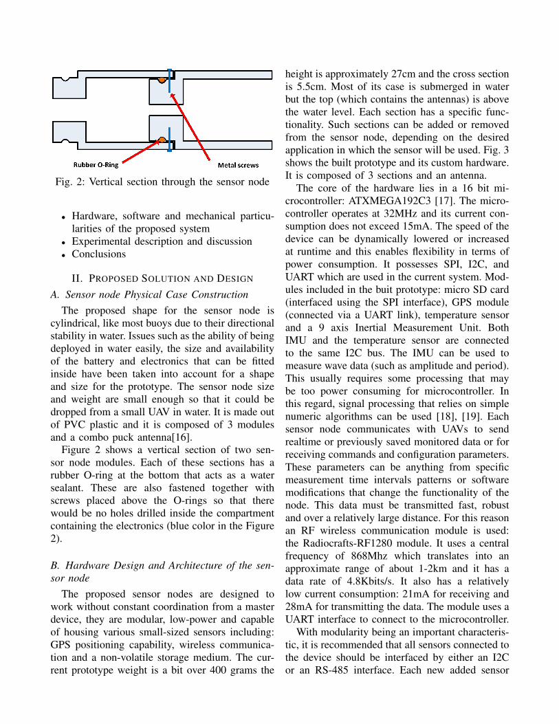
Fig. 2: Vertical section through the sensor node
• Hardware, software and mechanical particu-larities of the proposed system
• Experimental description and discussion• Conclusions
II. PROPOSED SOLUTION AND DESIGN
A. Sensor node Physical Case ConstructionThe proposed shape for the sensor node is
cylindrical, like most buoys due to their directionalstability in water. Issues such as the ability of beingdeployed in water easily, the size and availabilityof the battery and electronics that can be fittedinside have been taken into account for a shapeand size for the prototype. The sensor node sizeand weight are small enough so that it could bedropped from a small UAV in water. It is made outof PVC plastic and it is composed of 3 modulesand a combo puck antenna[16].
Figure 2 shows a vertical section of two sen-sor node modules. Each of these sections has arubber O-ring at the bottom that acts as a watersealant. These are also fastened together withscrews placed above the O-rings so that therewould be no holes drilled inside the compartmentcontaining the electronics (blue color in the Figure2).
B. Hardware Design and Architecture of the sen-sor node
The proposed sensor nodes are designed towork without constant coordination from a masterdevice, they are modular, low-power and capableof housing various small-sized sensors including:GPS positioning capability, wireless communica-tion and a non-volatile storage medium. The cur-rent prototype weight is a bit over 400 grams the
height is approximately 27cm and the cross sectionis 5.5cm. Most of its case is submerged in waterbut the top (which contains the antennas) is abovethe water level. Each section has a specific func-tionality. Such sections can be added or removedfrom the sensor node, depending on the desiredapplication in which the sensor will be used. Fig. 3shows the built prototype and its custom hardware.It is composed of 3 sections and an antenna.
The core of the hardware lies in a 16 bit mi-crocontroller: ATXMEGA192C3 [17]. The micro-controller operates at 32MHz and its current con-sumption does not exceed 15mA. The speed of thedevice can be dynamically lowered or increasedat runtime and this enables flexibility in terms ofpower consumption. It possesses SPI, I2C, andUART which are used in the current system. Mod-ules included in the buit prototype: micro SD card(interfaced using the SPI interface), GPS module(connected via a UART link), temperature sensorand a 9 axis Inertial Measurement Unit. BothIMU and the temperature sensor are connectedto the same I2C bus. The IMU can be used tomeasure wave data (such as amplitude and period).This usually requires some processing that maybe too power consuming for microcontroller. Inthis regard, signal processing that relies on simplenumeric algorithms can be used [18], [19]. Eachsensor node communicates with UAVs to sendrealtime or previously saved monitored data or forreceiving commands and configuration parameters.These parameters can be anything from specificmeasurement time intervals patterns or softwaremodifications that change the functionality of thenode. This data must be transmitted fast, robustand over a relatively large distance. For this reasonan RF wireless communication module is used:the Radiocrafts-RF1280 module. It uses a centralfrequency of 868Mhz which translates into anapproximate range of about 1-2km and it has adata rate of 4.8Kbits/s. It also has a relativelylow current consumption: 21mA for receiving and28mA for transmitting the data. The module uses aUART interface to connect to the microcontroller.
With modularity being an important characteris-tic, it is recommended that all sensors connected tothe device should be interfaced by either an I2Cor an RS-485 interface. Each new added sensor
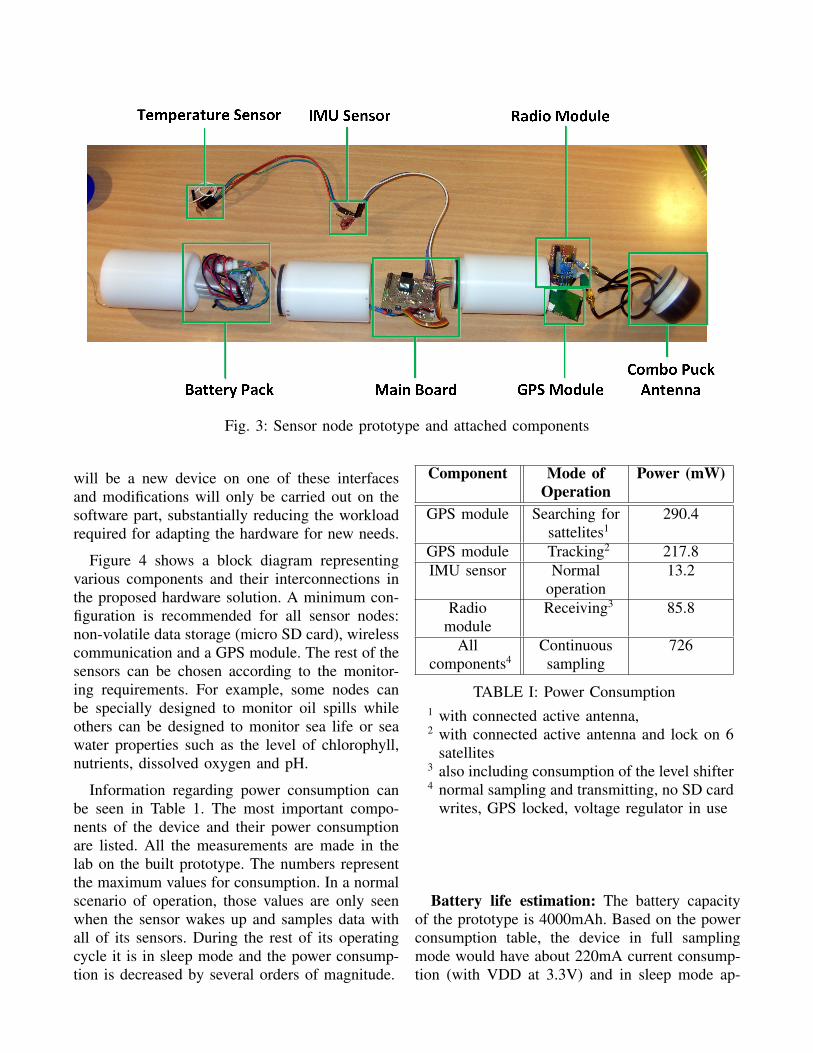
Fig. 3: Sensor node prototype and attached components
will be a new device on one of these interfacesand modifications will only be carried out on thesoftware part, substantially reducing the workloadrequired for adapting the hardware for new needs.
Figure 4 shows a block diagram representingvarious components and their interconnections inthe proposed hardware solution. A minimum con-figuration is recommended for all sensor nodes:non-volatile data storage (micro SD card), wirelesscommunication and a GPS module. The rest of thesensors can be chosen according to the monitor-ing requirements. For example, some nodes canbe specially designed to monitor oil spills whileothers can be designed to monitor sea life or seawater properties such as the level of chlorophyll,nutrients, dissolved oxygen and pH.
Information regarding power consumption canbe seen in Table 1. The most important compo-nents of the device and their power consumptionare listed. All the measurements are made in thelab on the built prototype. The numbers representthe maximum values for consumption. In a normalscenario of operation, those values are only seenwhen the sensor wakes up and samples data withall of its sensors. During the rest of its operatingcycle it is in sleep mode and the power consump-tion is decreased by several orders of magnitude.
Component Mode ofOperation
Power (mW)
GPS module Searching forsattelites1
290.4
GPS module Tracking2 217.8IMU sensor Normal
operation13.2
Radiomodule
Receiving3 85.8
Allcomponents4
Continuoussampling
726
TABLE I: Power Consumption1 with connected active antenna,2 with connected active antenna and lock on 6
satellites3 also including consumption of the level shifter4 normal sampling and transmitting, no SD card
writes, GPS locked, voltage regulator in use
Battery life estimation: The battery capacityof the prototype is 4000mAh. Based on the powerconsumption table, the device in full samplingmode would have about 220mA current consump-tion (with VDD at 3.3V) and in sleep mode ap-

Fig. 4: Overall Hardware Block DiagramArchitecture and Interconnects
proximatively 5mA1. The battery life for a scenarioin which the device samples data2 for 5 minutesevery hour is about 1 week. But not all applica-tions require this kind of sampling frequency. Forexample monitoring during the night might not beneeded all the time and wireless communicationcan be turned on only in specific pre-definedperiods in which the devices expects a UAV flying
1including the voltage regulator loss and current running throughsome passive components connected to the microcontroller in sleepmode
2with all sensors and wireless communication turned on
around to collect data. If no radio communicationis used and the devices only samples data 3 timesevery day, the battery life would be extended to27 days. These calculations provide only a generalestimate for the built prototype hardware and mayvary for other scenarios and sensor configurations.
C. Software Architecture of the sensor node
The software running on the embedded deviceis a state machine. Figure 5 represents the mainsystem states and their transition. The system hasan initial state to which it cannot switch back toonce it has been completed except for reset. Thisinitial state is mainly responsible for the startingup of the system, loading of the drivers, initializ-ing the filesystem, configuring the microcontrollerfrequencies, allocating the necessary memory forthe peripherals used and performing an initial self-check and calibration of the sensors. Another stateis the monitoring state. This is how the devicewill behave most of the time. During this stateit samples data from the sensors and stores itfor later transmission or sends it in realtime toany surrounding UAV. The third state in whichthe device can be is the command and control.The device transits from the monitoring state tocommand and control state only when the UAVissues a specific command. If the device enters thecommand and control state it waits for commandsfrom the UAV or a timeout, before it can resumenormal sensor sampling. The commands can besimple identification requests, or reconfiguring thedevice parameters (change of sampling rates forthe sensors, deactivating certain sensors, etc.). Thedevice can go into sleep mode either at specificpre-programmed time intervals or when issued bya command coming from a UAV.
Figure 6 shows the dynamic workflow of thesoftware on the sensor node, starting from theinitial state and proceeding to the monitoring state.Each of these steps are described below:
• Configure MCU internals. It is the firstset of operations carried out by the micro-controller. It configures the clock systems,interrupt routines and allocates the necessarydata memory. At this point an interrupt routineis started. This routine is dedicated to handing
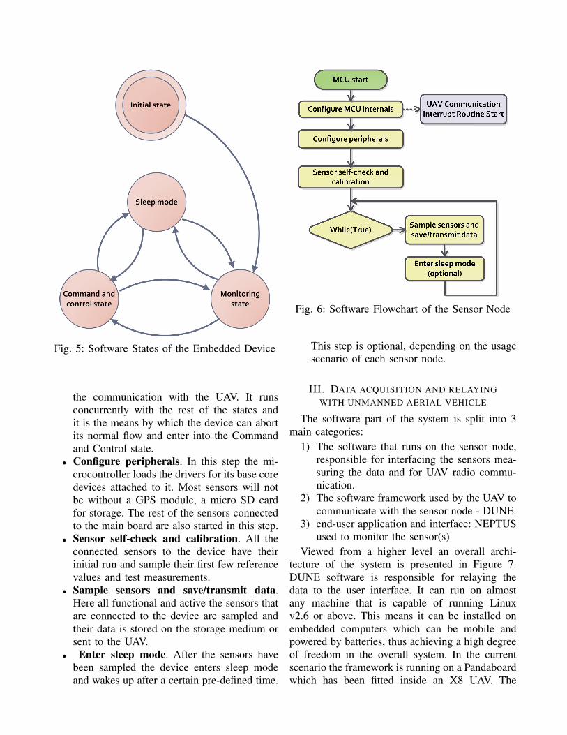
Fig. 5: Software States of the Embedded Device
the communication with the UAV. It runsconcurrently with the rest of the states andit is the means by which the device can abortits normal flow and enter into the Commandand Control state.
• Configure peripherals. In this step the mi-crocontroller loads the drivers for its base coredevices attached to it. Most sensors will notbe without a GPS module, a micro SD cardfor storage. The rest of the sensors connectedto the main board are also started in this step.
• Sensor self-check and calibration. All theconnected sensors to the device have theirinitial run and sample their first few referencevalues and test measurements.
• Sample sensors and save/transmit data.Here all functional and active the sensors thatare connected to the device are sampled andtheir data is stored on the storage medium orsent to the UAV.
• Enter sleep mode. After the sensors havebeen sampled the device enters sleep modeand wakes up after a certain pre-defined time.
Fig. 6: Software Flowchart of the Sensor Node
This step is optional, depending on the usagescenario of each sensor node.
III. DATA ACQUISITION AND RELAYINGWITH UNMANNED AERIAL VEHICLE
The software part of the system is split into 3main categories:
1) The software that runs on the sensor node,responsible for interfacing the sensors mea-suring the data and for UAV radio commu-nication.
2) The software framework used by the UAV tocommunicate with the sensor node - DUNE.
3) end-user application and interface: NEPTUSused to monitor the sensor(s)
Viewed from a higher level an overall archi-tecture of the system is presented in Figure 7.DUNE software is responsible for relaying thedata to the user interface. It can run on almostany machine that is capable of running Linuxv2.6 or above. This means it can be installed onembedded computers which can be mobile andpowered by batteries, thus achieving a high degreeof freedom in the overall system. In the currentscenario the framework is running on a Pandaboardwhich has been fitted inside an X8 UAV. The

Fig. 7: Communication flow between the sensornode, the UAV running DUNE and a computer
running NEPTUS
Pandaboard is connected via a UTP cable to aRocket M5 5GHz AirMax wireless radio deviceand with the Radiocraft-RF1280 Radio moduleusing the serial port. A DUNE task has beenprogrammed to read the incoming data from theserial port (radio link with the sensor node), parseit and pack it into IMC messages packages and tosend these packages to a ground station runningNEPTUS via a 5 GHz link. The protocol usedfor the wireless radio link between the UAV andthe sensor node is custom built based on the IMCprotocol: non-relevant data packets present in IMCsuch as timestamp have been removed in order tominimize unnecessary traffic over the low powerradio link. IMC messages are sent through thenetwork as UDP packets.
One possibility in which a UAV can collectdata from a sensor node is as follows: A sensornode can be preprogrammed to constantly sendthe sampled data at a predefined time intervalwhile the UAV flying above the sensor is constanlyreading for incoming data. Alternatively, the UAVcan wake-up the sensor node when it comes inrange with it and issue a read transaction. Toconserve as much power as possible the UAV isthe one that continually polls for signals comingfrom the sensor node. The unit sends basic ping
messages at configurable time interval. When anyof these messages are received by the UAV it issuesa wake-up command to the sensor and that in turnstarts sending data to the UAV.
IV. TESTS AND RESULTS
Tests have been performed in order to check thefeasibility of the entire system as described in Fig.7.
Test scenario and setup: Hopavagen, Agdenes,Norway was selected for the test location. Thesensor node has been placed next to the shore inshallow waters, (about 1m deep) anchored to theground using rope. The UAV was loitering above itto collect its data and to forward it to a base station.Figure 8) shows the UAV and its payload. In this
Fig. 8: X8 UAV payload
test scenario the sensor node has been programedto sample data at a fixed timed interval, send itto the UAV and log it to the SD card as well.No sleep modes were used. The data sent by thesensor node is composed of temperature read andits GPS coordinates. The DUNE task running onthe Pandaboard performs the following:
• reads the data coming from the sensor nodeand logs it in its own not-volatile memory
• sends an acknowledge message back to thesensor node
• forwards the received sensor data via the5GHz link to the base station.
The base station is a computer running NEPTUSsoftware which is also connected to a ROCKET
M5 5GHz 2x2 MIMO AirMax TDMA BaseSta-tion.
Test Results: The flight time was approximately12 minutes. The maximum distance at which theUAV was situated from the sensor node was 264m(measured using Google maps) and the maximumaltitude measured during tests was approximately100m. Within this distance, for the entire flighttime there was a valid data link between the sensornode, the UAV and the base station. Previousexperiments carried out by the author[20] haveshown that the Radiocraft modules can commu-nicate further than 600m, meaning that this testscenario was well within the previously testedlimitations of the radio device. Figure 10 showsthe generated flight trajectory logged by the UAV.During the test 344 data packages (IMC Messages)representing sensor readings were sent from thesensor node to the UAV. Out of these, 3 weredropped as having a CRC fail. The size of an IMCmessage ranges between a few tens to hundreds ofbytes [21]. Two packages (GPS fix and tempera-ture) were sent every 1200 milliseconds from thesensor node to the UAV. Precisely measuring thelink speed during the flight test was not the mainpurpose of the experiment, but some estimatescan be presented: The link between the UAV andthe base station was done by interconnecting twoROCKET M5 AirMax Base Stations. Since theywere at a maximum distance of 264m during theflight, the data rate would be in the range of tensof mbps 3 [22]. The maximum data rate for theradio device used to make the communication linkbetween the sensor node and the UAV is 4.8KB/s[23].
Figure 9 shows NETPUS command interfaceshowing the sensor node on the map, its coordi-nates and its temperature readings. Further techni-cal details and more in depth test results for thisproject can be found at [20]. A video of the flighttests (including weather conditions and experimentsetup) is available in: [24].
3Even though the devices are 5GHz capable, the networkinginterface with the PC/embedded computer is done using a 10/100BASE-TX Ethernet Interface, limiting the whole system to 100mbps
V. CONCLUSIONS
With regard to other similar solutions, some keydifferences between what has already been madein this field and what was described above are:
• The sensor nodes are modular and can be eas-ily adapted to new environments, both fromsoftware and hardware point of view.
• The ecosystem around the sensor nodes usesopen source software that is compatible withmost operating systems and has very flexiblehardware requirements [15].
• Because of their adaptability, the sensor nodesare meant to be used together and intercon-nected with other types UAS and AUVs andeven other sensor types.
The results of the tests suggest that the designedsystem can be used in the monitoring applicationslisted in the introduction. Some particular conclu-sions following the tests are:
• The tested range of the radio devices andantennas used in the sensor node proved tobe sufficient, allowing for a good sensor nodeto UAV communication.
• The proposed physical case design proved tofloat in the water, be directionally stable andwater-tight.
• The designed PCB and firmware in the em-bedded device have properly met the applica-tion requirements
• DUNE software framework was found to besuitable for this type data acquisition scenar-ios
• NEPTUS command interface can be usedwith ease for displaying senor readings forsuch application types.
The research and work that has been carried outso far and the prototype built lead us to concludethat the approach and the idea for the project sofar is valid. The DUNE and NEPTUS softwareused is open source, making it free, easy to ex-pand, upgrade and debug, having a community ofdevelopers that support it.
VI. ACKNOWLEDGMENTS
This work was supported by the Research Coun-cil of Norway through the Centers of Excellencefunding scheme, Project number 223254 - Centre

Fig. 9: Screen capture of Neptus showing the sensor node being placed in the water
Fig. 10: Flight trajectory of the UAV during the test (generated with Google Earth)

for Autonomous Marine Operations and Systems(AMOS). The authors are grateful for the assis-tance provided by the team at NTNU, in particularFrederik Leira, Kristian Klausen, Jo Arve Alfred-sen, John Olav Horrigmo, Per Inge Snildal, TerjeHaugen, Lars Semb and Torkel Hansen, and theteam at University of Porto, in particular JoaoFortuna, Filipe Ferreira and Joao Sousa.
REFERENCES
[1] P. McGillivary, J. B. de Sousa, R. Martins, K. Rajan, andF. Leroy, “Integrating autonomous underwater vessels, surfacevessels and aircraft as persistent surveillance components ofocean observing studies,” in IEEE/OES Conf. AutonomousUnderwater Vehicles (AUV), 2012.
[2] M. Faria, J. Pinto, F. Py, J. Fortuna, H. Dias, R. Martins,F. Leira, T. A. Johansen, J. Sousa, and K. Rajan, “Coordi-nating UAVs and AUVs for oceanographic field experiments:Challenges and lessons learned experiments in UAV and AUVcontrol for coastal oceanography,” in Proc. IEEE Int. Conf.Robotics and Automation, Hong Kong, 2014.
[3] V. E. Hovstein, A. Sægrov, and T. A. Johansen, “Experienceswith coastal and maritime UAS BLOS operation with phased-array antenna digital payload data link,” in Int. Conf. Un-manned Aerial Systems (ICUAS), Orlando, 2014.
[4] T. A. Johansen, A. Zolich, T. Hansen, and A. J. Sorensen,“Unmanned aerial vehicle as communication relay for au-tonomous underwater vehicle - field tests.” Austin, TX: IEEEGlobecom Workshop - Wireless Networking and Control forUnmanned Autonomous Vehicles, 2014.
[5] D. T. Ho, E. I. Grotli, P. B. Sujit, and T. J. Borges De Sousa,“Performance evaluation of cooperative relay and particleswarm optimization path planning for uav and wireless sensornetwork.” Atlanta: Globecom Workshop - Wireless Network-ing and Control for Unmanned Autonomous Vehicles, 2013.
[6] “Catalina sea ranch and the nomadbuoy,” 2014. [Online]. Available: catalinasear-anch.com/Catalinasearanch.com/Monitoring.html
[7] D. Roemmich, G. C. Johnson, S. Riser, R. Davis, J. Gilson,W. B. Owens, S. L. Garzoli, C. Schmid, and M. Ignaszewski,“The argo program: Observing the global ocean with profilingfloats,” in Oceanography, vol. 22, 2009.
[8] K. S. Zaidi, V. Jeoti, and A. Awang, “Wireless backhaulfor broadband communication over sea,” in IEEE MalaysiaInternational Conference on Communications (MICC), 2013,pp. 298–303.
[9] S. Ohmori, A. Irimata, H. Morikawa, K. Kondo, Y. Hase, andS. Miura, “Characteristics of sea reflection fading in maritimesatellite communications,” in IEEE Transactions on Antennasand Propagation, vol. 33, Aug 1985, pp. 838–945.
[10] Argo Science Team 2001, “Argo: The global array of profilingfloats.” GODAE Project Office and Bureau of Meteorology,2011.
[11] N. Smith, “The global ocean data assimilation experiment,”in Advances in Space Research, vol. 25, 2000.
[12] J. W. Hurrell, M. Visbeck, A. Busalacchi, R. A. Clarke, T. L.Delworth, R. R. Dickson, W. E. Johns, K. P. Koltermann,Y. Kushnir, D. Marshall, C. Mauritzen, M. S. McCartney,A. Piola, C. Reason, G. Reverdin, F. Schott, R. Sutton,
I. Wainer, and D. Wright, “Atlantic climate variability andpredictability: A CLIVAR perspective,” in Journal of Climate,vol. 19, 2006.
[13] C. Meinig, S. E.Stalin, A. I. Nakamura, H. B. Milburn,R. L. Molinari, S. L. Garzoli, and G. C. Johnson, “Thenoaa dart ii description and disclosure,” in Real-Time Deep-Ocean Tsunami Measuring, Monitoring, and Reporting Sys-tem, 2005.
[14] Stephen R. Pratt, Richard A. Raines, Carl E. Fossa Jr.,and Michael A. Temple, “An operational and performanceoverview of the IRIDIUM low earth orbit satellite system,”in IEEE Communications Surveys, 1999.
[15] J. Pinto, P. S. Dias, R. Martins, J. Fortuna, E. Marques,and J. Sousa, “The LSTS toolchain for networked vehiclesystems,” in MTS/IEEE OCEANS, Bergen, 2013.
[16] “MA104 GPS/cellular combo hercules penta-band cellular antenna,” in Specification DocumentMA104.C.A301111.B301111. Taoglas antenna solutions.
[17] “Atxmega c3 documentation,” De-cember 2014. [Online]. Available:http://www.atmel.com/devices/ATxmega192C3.aspx
[18] Havard Fjaer Grip, Thor I. Fossen, Tor A. Johansen, and AliSaberi, “Attitude estimation using biased gyro and vector mea-surements with time-varying reference vectors,” in AutomaticControl, vol. 57. IEEE Trans, 2012, pp. 1332–1338.
[19] H. F. Grip, T. I. Fossen, T. A. Johansen, and A. Saberi,“Nonlinear observer for GNSS-aided inertial navigation withquaternion-based attitude estimation.” American ControlConference (ACC), 2013, pp. 272 – 279.
[20] Remus Barbatei, “Data acquisition with unmanned aerialvehicle (UAV) from floating sensor nodes,” in Master Thesis.Norwegian University of Science and Technology, Depart-ment of Engineering Cybernetics, 2014.
[21] “Detailed imc message format,” December 2014. [Online].Available: http://lsts.pt/docs/imc/imc-5.4.3/Sensors.html
[22] “Ubiquiti Networks Technical Specs Document,” June 2014.[Online]. Available: https://www.ubnt.com/airmax/rocketm/
[23] “Radiocrafts technical specs document,” April 2014. [Online].Available: http://www.radiocrafts.com/index.php?sideID=246
[24] “UAV and floating sensor node wa-ter tests,” June 2014. [Online]. Available:https://www.youtube.com/watch?v=d3XSWpmu6tk