Embed Size (px)
Citation preview

Acoustic Treatment One
1
Acoustic Treatment –- one (Noise and Vibration Control)
MEBS 6008

Acoustic Treatment One
2
Heat radiation operation (all cooling operation)
Heat recovery operation (cooling & heating operation)
Heat absorption tendency heat recovery operation (mainly heating, part cooling operation)
Heat absorption operation (all heating operation)
VRV with Heat Pump

Acoustic Treatment One
3
Balanced vs unbalanced air flows
Exhaust air flow/ supply air flow
Sensible Effectiveness
1 0.5 90%
2 0.55 85%
3 0.6 80%
4 0.65 75%
5 0.7 70%
6 0.75 65%
Unbalanced flow increase effectiveness of heat exchanger
Heat exchanger transfer less overall heat, why?
The following example illustrates the reasons:
Balanced Flow
Unbalanced Flow
4.7 cub.m.
4.7 cub.m
35.7 deg C
31.9 deg C
28.9 deg C
25.6 deg C
4.7 cub.m.
35.7 deg C
30.0 deg C
33.2 deg C3.3 cub.m.
25.6 deg C

Acoustic Treatment One
4

Acoustic Treatment One
5
Hot gas Bypass ?????
Do you want to ask ???
Hot gas Bypass Line
Hot gas bypass diverts hot, high-pressure refrigerant vaporfrom the discharge line to low-pressure side of refrigeration system.
This added “false load” to maintain an acceptable suction pressure andtemperature.
Hot gas bypass not reduce energy consumption (not allow the compressor to shut off at low load)

Acoustic Treatment One
6
What is Sound?
Audible emissions from vibration of molecules within an elastic medium
Generated by vibrating surface or movement of a fluid
Through air or structure
Noise is unwanted sound

Acoustic Treatment One
7
ACOUSTICAL DESIGN OBJECTIVE
The primary objective for the acoustical design of HVAC systems and equipment is to ensure that the acoustical environment in a given space is not degraded.
Sound and vibration are created by a source, are transmitted along one or more paths, and reach a receiver.
Treatments and modifications can be applied to any or all of these elements to achieve an acceptable acoustical environment.

Acoustic Treatment One
8
CHARACTERISTICS OF SOUND
Sound is a propagating disturbance in a fluid (gas or liquid) or in a solid.
In fluid media, the disturbance travels as a longitudinal compression wave.
Airborne sound
Sound in air is called airborne sound or simply sound.
Generated by a vibrating surface or a turbulent fluid stream.
Structure borne sound
In solids, sound travels as bending waves, compression waves, torsion waves, shear waves and others.
Sound in solids is generally called structure borne sound.
In HVAC system design, both airborne and structure borne sound propagation are important.

Acoustic Treatment One
9
What is frequency?
Comparison of Pitch and Frequency
FrequencyFrequency
- an objective quantity
- independent of sound-pressure level.
PitchPitch
- subjective quantity
- primarily based on frequency
- dependent on sound-pressure level and composition
- not measured
- described with terms like bass and tenor

Acoustic Treatment One
10
The speed of sound transmission depend on the physical property of the medium.
For air, the speed varies slightly with temperature change.
The speed of sound = a constant (344 m/s) in consideration of narrow temperature range in HVAC system.
Sound traveling through the air at a frequency of 200 Hz has a wavelength of 1.7 m.
Speed of Sound and Wavelength

Acoustic Treatment One
11
Sounds are of a broadband nature,
Sound is composed of several frequencies and amplitudes, all generated at the same time.
The sound energy is greater at some frequencies than at others.
Sound

Acoustic Treatment One
12
Octave Bands
Human ear perception: sounds at frequencies 20 to 16,000 Hz,
HVAC system sounds 45 to 11,200 Hz (11,156 data points).
HVAC sounds frequencies smaller ranges (octave bands).
The highest frequency in the band is two times the lowest frequency.
Center frequency = square root of the product of the lowest and highest frequencies in the band.
The frequency range (45 to 11,200 Hz) eight octave bands with center frequencies of 63, 125, 250, 500, 1,000, 2,000, 4,000, and 8,000 Hz.

Acoustic Treatment One
13
• Acoustical energy emitted by the sound source
• Unaffected by the environment
• Expressed in terms of watts (W)
Sound Power and Sound Pressure
Sound power
Sound pressure• Pressure disturbance in the atmosphere
• Expressed in terms of Pascal (Pa) Can be measured directly
• What our ears hear and what sound meters measure
• Affected by strength of source, surroundings, and distance between source and receiver
• Affected by strength of source, surroundings, and distance between source and receiver
• Also Affected by room is carpeted or tiled/ furnished or bare

Acoustic Treatment One
14
Sound Level
The loudest sound the human ear can hear = 1,000,000,000 x perceptible sound
A logarithmic scale is used.
A decibel is a calculated value
A decibel is based on the ratio of measured and reference values.
It is defined as shown on the left equation

Acoustic Treatment One
15
Sound Power Level
The reference value used for calculating sound-power level is 10-12 watts.
Sound-power level (Lw) in dB is calculated using the upper left equation
Sound Pressure
The reference value used for calculating sound-pressure level is 2 ×10⁻⁵ Pa.
Sound-pressure level (Lp) in dB is shown on the lower left equation
Sound power is proportional to the square of sound pressure multiplier 20 is used (not 10).
Reference values are the threshold of hearing.

Acoustic Treatment One
16

Acoustic Treatment One
17
The sensation of loudness = f(sound pressure & frequency).
Each contour approximates an equal loudness level across the frequency range shown.
Human ear is more sensitive to high frequencies than low frequencies.
Ear’s sensitivity at a particular frequency changes with sound-pressure level.
Loudness Contour
Loudness to human ear : 60 dB 100 Hz = 50 dB at 1,000 Hz.
Human ears are less sensitive to low-frequency sounds.
Contours are flatter at higher decibels a more uniform response to “loud” sounds.
Human ear not respond linearly to pressure and frequency.
1

Acoustic Treatment One
18
Single-Number Rating Methods
Human ear : sound as loudness and pitch
Electronic Sound-measuring equipment : Sound as pressure and frequency.
Most frequent single-number descriptors to express both the intensity and quality of a sound :–
1) A-weighting network
2) Noise criteria (NC)
3) Room criteria (RC)

Acoustic Treatment One
19
Steps to calculate A-weighted Sound Pressure Level
1) List actual sound-pressure levels for the eight octave bands
2) Add or subtract the decibel values represented by the A-weighting curve.
3) Logarithmically sum all eight octave bands to get an overall A-weighted sound-pressure level.
A-weighted Sound Pressure Level - Example
A-weighted sound-pressure level is 42 dBA in this example.
Most sound meters can automatically calculate and display the A-weighted sound-pressure level.
Acoustic Treatment One
20
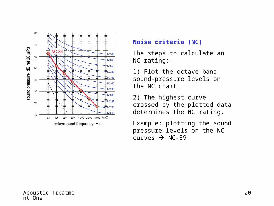
Noise criteria (NC)
The steps to calculate an NC rating:-
1) Plot the octave-band sound-pressure levels on the NC chart.
2) The highest curve crossed by the plotted data determines the NC rating.
Example: plotting the sound pressure levels on the NC curves NC-39
Acoustic Treatment One
21
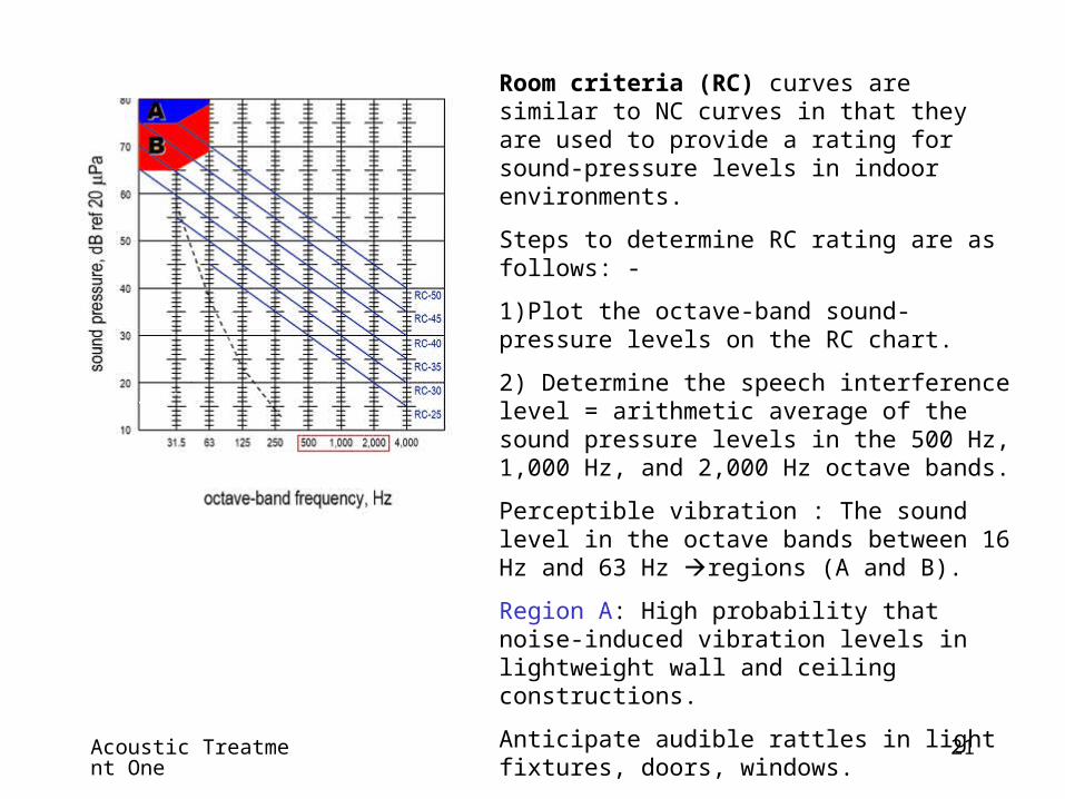
Room criteria (RC) curves are similar to NC curves in that they are used to provide a rating for sound-pressure levels in indoor environments.
Steps to determine RC rating are as follows: -
1)Plot the octave-band sound-pressure levels on the RC chart.
2) Determine the speech interference level = arithmetic average of the sound pressure levels in the 500 Hz, 1,000 Hz, and 2,000 Hz octave bands.
Perceptible vibration : The sound level in the octave bands between 16 Hz and 63 Hz regions (A and B).
Region A: High probability that noise-induced vibration levels in lightweight wall and ceiling constructions.
Anticipate audible rattles in light fixtures, doors, windows.
Region B: Noise-induced vibration levels in lightweight wall and ceiling constructions may be felt.
Slight possibility of rattles in light fixtures, doors, windows.

Acoustic Treatment One
22
Setting a Design Goal
The first step of an acoustical design is to quantify the goal.
Several single-number descriptors that designers commonly use to define the acoustical design goal for a space.
Each descriptor has its advantages its and drawbacks.
In general, when defining the acoustical design goal for an interior space, either an NC value or an RC value is used.

Acoustic Treatment One
23
• A balanced distribution of sound energy over a broad frequency range
• No audible tonal or other characteristics such as whine, whistle, hum, or rumble
• No noticeable time-varying levels from beats or other system induced aerodynamic instability
• No fluctuations in level such as a throbbing or pulsing
Other goals to be achieved:
Setting a Design Goal

Acoustic Treatment One
24
1. Noise from domestic premises and public places (often referred to as general neighbourhood noise);
2. Noise from construction activities (including piling);
3. Noise from places other than domestic premises, public places or construction sites (for example, noise from industrial or commercial premises);
4. Noise from intruder alarm system installed in any premises or vehicle;
5. Noise from individual items of plant or equipment (referred to in the Ordinance as Product Noise, for example, noise from hand-held breaker and air compressor); and
6. Noise emission from motor vehicles.
The Noise Control OrdinanceNoise Control Ordinance deals with the following forms of noise:
When defining the acoustical design goal for an outdoor environment, to meet noise ordinance for example, the Environmental Protection Department specified A-weighted scale.

Acoustic Treatment One
25
Environmental Protection Department, HKSARG

Acoustic Treatment One
26

Acoustic Treatment One
27

Acoustic Treatment One
28
Source–path–receiver model This modeling method traces sound from the source to the receiver.
How the sound travels between the source and the receiver, and everything it encounters as it travels along the way, constitutes the path.
The receiver is the person working in the adjacent conditioned space.
The supply duct provides one of the paths for sound to travel from the source to the receiver.
To specify the maximum allowable equipment sound power not exceeding the sound-pressure target for the space.

Acoustic Treatment One
29
Typical Sound Paths
Airborne
Sound that travels through supply ductwork, return ductwork, or an open plenum
Can travel with or against the direction of airflow
Breakout
Sound that breaks out through the walls of the supply
or return ductwork
Transmission
Sound that travels through walls, floors, or ceilings

Acoustic Treatment One
30
Identifying Sound Sources and Paths
One piece of equipment may contain several sound sources.
For example,a packaged rooftop air conditioner contains supply and exhaust (or return) fans, compressors, and condenser fans.
Sound may travel from a single source to the receiver along multiple paths: supply airborne, supply breakout, return airborne, and transmission through the adjacent wall.
The total sound heard = the sum of all the sounds from various sources traveling along several paths.
Supply airborne path contributes to the total sound-pressure level in the space much more than the other three paths.

Acoustic Treatment One
31
In theory, a free field is a homogeneous, isotropic medium that is free from boundaries.
In practice, an example of a free field over a reflecting plane would be a large open area void of obstructions.
An ideal sound source, that is, one that radiates sound equally in all directions, placed in a free field generates sound-pressure waves in a spherical pattern.
At equal distances from the source, the sound pressure is same in all directions.
As the sound waves travel farther away from the source, the area of the sphere increases.
Doubling of the distance from the source spreads the sound over four times as much surface area.
Free field

Acoustic Treatment One
32
The near field is an area adjacent to the source where sound not behave as in a free field.
Most sound sources, including all HVAC equipment, do not radiate sound in perfectly spherical waves.
This is due to the irregular shape of the equipment and different magnitudes of sounds radiating from the various surfaces of the equipment.
These irregularities cause pressure-wave interactions the behavior of the sound waves unpredictable.
Sound-pressure measurements should not, therefore, be made in the near field.
The size of the near field depends on the type of source and dimensions of the equipment.
Near field

Acoustic Treatment One
33
Reverberant Field
A reverberant field is nearly the opposite of a free field. Reverberant fields exist in rooms with reflective walls, floors, and ceilings.
When a sound source is placed in an enclosed room, the sound waves from the source bounce back and forth between the reflective walls many times.
This can create a uniform, or diffuse, sound field.
In a perfectly reverberant room, the sound-pressure level is equal at all points within the room.

Acoustic Treatment One
34
Semi-reverberant field Buildings are somewhere between a free field and a reverberant field environment.
The walls, floor, and ceiling prevent the sound from behaving as it would in a free field.
Some of the sound is reflected by these surfaces ( but a portion of the sound is absorbed or transmitted).
The characteristics of the sound field change with distance when a small sound source is placed in the center of a room.
Close to the source, in the near field, sound measurement is unpredictable.
Near the wall, in the reverberant field, the reflected sound begins to add to the sound coming directly from the source.
The reduction in sound level due to the distance from the source tends to be cancelled out by the addition of the sound reflecting off the wall a near-constant sound-pressure level near the wall.
Semi-reverberant field

Acoustic Treatment One
35
Free-Field Method

Acoustic Treatment One
36
This equation is used to determine how loud a piece of equipment will be at a given distance.
For example, the manufacturer of an aircooled chiller lists the sound-pressure level of the chiller as 95 dB at a distance of 9.1 m from the chiller.
The sound-pressure level at 36.6 m from the chiller is 83 dB.
Acoustic Treatment One
37
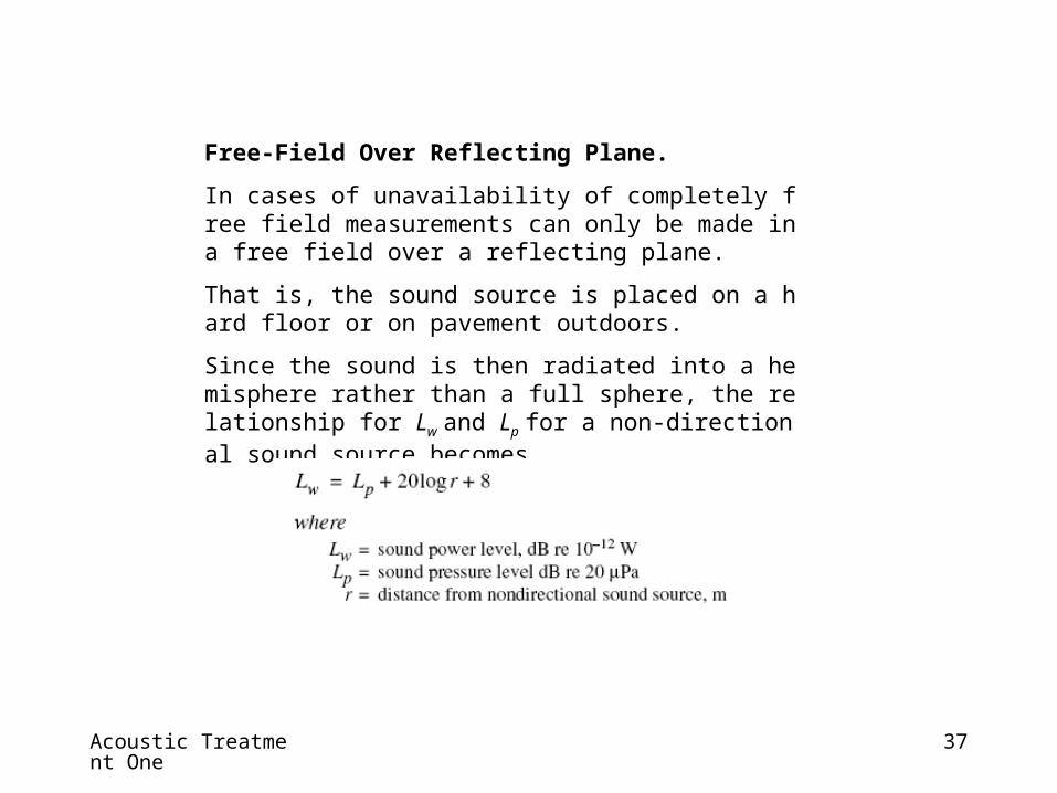
Free-Field Over Reflecting Plane.
In cases of unavailability of completely free field measurements can only be made in a free field over a reflecting plane.
That is, the sound source is placed on a hard floor or on pavement outdoors.
Since the sound is then radiated into a hemisphere rather than a full sphere, the relationship for Lw and Lp for a non-directional sound source becomes
Acoustic Treatment One
38
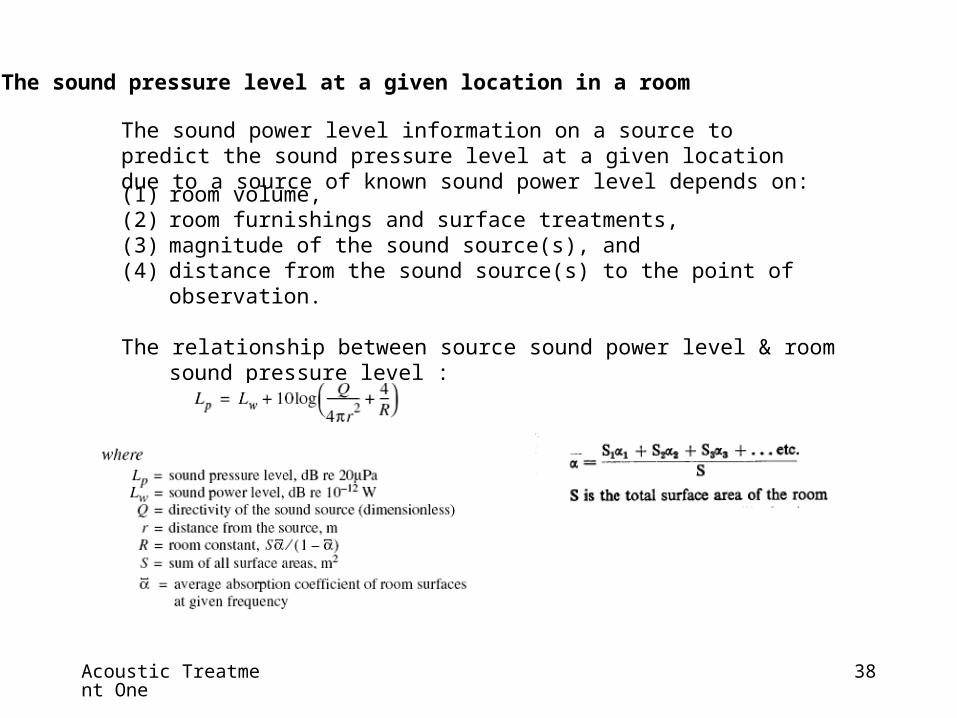
(1) room volume,(2) room furnishings and surface treatments, (3) magnitude of the sound source(s), and (4) distance from the sound source(s) to the point of observation.
The relationship between source sound power level & room sound pressure level :
The sound pressure level at a given location in a room
The sound power level information on a source to predict the sound pressure level at a given location due to a source of known sound power level depends on:

Acoustic Treatment One
39

Acoustic Treatment One
40
Insertion loss (IL)
The difference in sound pressure measured in a single location with and without a noise-control device located between the source and receiver.
The difference in the sound pressure measured in the occupied space with the wall versus without the wall is the IL of the wall
Sound transmission loss (TL) of a partition or other building element
It equals 10 times the logarithm (base 10) of the ratio of the airborne sound power incident on the partition to the sound power transmitted by the partition and radiated on the other side.
The quantity so obtained is expressed in decibels.

Acoustic Treatment One
41
Transmission loss (TL)
It also depends on material properties, such as stiffness and internal damping.
16 mm gypsum boardTL depends mainly on the surface mass of the wall at frequencies below about 1 kHz (match with mass law)
At higher frequencies, there is a dip in the TL curve (coincidence dip) the the wavelength of flexural vibrations in the wall coincides with the wavelength of sound in the air.
Critical frequency
The frequency where the minimum value of TL occurs in the coincidence dip
The stiffer or thicker the layer of material, the lower the critical frequency.
Transmission Loss of Partition

Acoustic Treatment One
42
Sound transmission through partitions

Acoustic Treatment One
43
Reduction in reverberant sound pressure level in a room due to the enclosure of a source in the same room:
Noise reduction due to enclosure

Acoustic Treatment One
44
Sound Barriers
A sound barrier is a solid structure that intercepts the direct sound path from a sound source to a receiver.
It reduces the sound pressure level within its shadow zone.
Figure illustrates the geometrical aspects of an outdoor barrier where no extraneous surfaces reflect sound into the protected area.
Scattering and refraction of sound into the shadow zone formed by the barrierthe limiting value of about 24 dB
Practical constructions, size and space restrictions often limit sound barrier performance to 10 to 15 dB.

Acoustic Treatment One
45

Acoustic Treatment One
46
Attenuation refers to the reduction in sound level as sound travels along the path from a source to a receiver( through a duct system).
Straight ducts, elbows, junctions, and silencers are examples of elements that attenuate sound.

Acoustic Treatment One
47
Regenerated sound results from components of the duct system that create turbulence in the air stream.
An abrupt change in airflow direction or velocity with a corresponding static-pressure lossTurbulence
Regenerated sound increases with air velocity or when the air is forced to make sharp turns.
Elbows, junctions, diffusers, silencers, and dampers regenerate sound.
Notice that some elements can both attenuate and regenerate sound.
Air makes a 90-degree turn in a rectangular duct elbow, some of the sound is reflected back upstream, attenuating the airborne sound downstream of the elbow.
The turbulence created by the air turning the sharp corner causes some regenerated sound.

Acoustic Treatment One
48
• The total sound energy that strikes a surface is either reflected, absorbed by the material, or transmitted through the material.
• A material provides a barrier to the incident sound energy when it reduces the amount of sound energy that is transmitted through the material.
• Materials that are dense (such as masonry block or wallboard) or stiff (such as glass) are generally better at reducing transmitted sound than materials that are lightweight or flexible.
• Increasing the thickness of a material reduces the amount of sound transmitted through it.
• High-frequency sound is more easily reduced than low-frequency sound when it pass through material.

Acoustic Treatment One
49
Noise reduction (NR)
The difference between sound-pressure measurements taken on each side of a barrier.
The NR for this same door is the difference in the sound-pressure level inside the office space, with the door closed, and on the other side of the door inside the equipment room.
Sound Absorption of Materials
Absorptive materials work by converting acoustical energy into heat energy.
The absorbed energy is the portion of the incident sound energy that is neither transmitted through the material nor reflected off the material.
The absorptivity of a material depends on several factors, including thickness, frequency of the sound, and whether there is a reflective surface located behind the absorptive material.
The absorptivity of a material is typically described in terms of an absorption coefficient.

Acoustic Treatment One
50
BASIC DESIGN TECHNIQUES
Selecting fans (or other related mechanical equipment) and designing air distribution systems + minimization of sound transmitted from different components to the occupied spaces :
Step 1- Design the air distribution system to minimize flow resistance and turbulenceStep 1- Design the air distribution system to minimize flow resistance and turbulence .
High flow resistance increases the required fan pressure, which results in higher noise being generated by the fan.
Turbulence increases the flow noise generated by duct fittings and dampers in the air distribution system(especially at low frequencies).

Acoustic Treatment One
51
BASIC DESIGN TECHNIQUES
Step 2 - Select of a fanStep 2 - Select of a fan
A fan operating close to its rated peak efficiency at design quantity of air and static pressure.
A fan generates the lowest possible noise at design conditions
Oversized or undersized fan not operate at or near rated peak efficiency substantially higher noise levels.
Step 3- design duct connections (the fan inlet and outlet) for uniform & straight air flow.Step 3- design duct connections (the fan inlet and outlet) for uniform & straight air flow.
Failure to do this can result in severe turbulence at the fan inlet and outlet and in flow separation at the fan blades significantly increase the noise generated by the fan.

Acoustic Treatment One
52
BASIC DESIGN TECHNIQUES
Step 4 - Selection of SilencerStep 4 - Selection of Silencer
Select duct silencers that do not significantly increase the fan total static pressure.
Duct silencers can significantly increase the required fan static pressure if improperly selected.
Selecting silencers with maximum static pressure losses of 87 Pa. minimize silencer airflow regenerated noise.

Acoustic Treatment One
53
BASIC DESIGN TECHNIQUES
Step 5 – fan powered mixing boxesStep 5 – fan powered mixing boxes
Place fan-powered mixing boxes associated with variable-volume air distribution systems away from noise-sensitive areas.
Step 6 – Flow at elbow/ duct branch takeoffStep 6 – Flow at elbow/ duct branch takeoff
Locating elbows or duct branch takeoffs at least five duct diameters apart Minimize flow-generated noise by them (10 dia for high vel and critical areas).
Step 7 – Flow velocity and duct areaStep 7 – Flow velocity and duct area
Keep airflow velocity in the duct as low as possible (max. 7.5 m/s) near critical noise areas by expanding the duct cross-section area.
Do not exceed an included expansion angle of greater than 15°(Flow separation, resulting from expansion angles greater than 15°, may produce rumble noise).
Expanding the duct cross-section area reduce potential flow noise associated with turbulence in these areas.

Acoustic Treatment One
54
BASIC DESIGN TECHNIQUES
Step 8 – Turning vanes at elbowsStep 8 – Turning vanes at elbows
Use turning vanes in large 90° rectangular elbows and branch takeoffs.
This provides a smoother transition for air smoothly change flow direction reducing turbulence.
Step 8 – Turning vanes at elbowsStep 8 – Turning vanes at elbows
Place grilles, diffusers and registers into occupied spaces as faras possible from elbows and branch takeoffs.
Step 9 - volume dampers near grills, diffusers and registers Step 9 - volume dampers near grills, diffusers and registers
Minimize the use of volume dampers near grills, diffusers and registers in acoustically critical situations.

Acoustic Treatment One
55
BASIC DESIGN TECHNIQUES
Step 10 – Vibration Isolators/ Flexible ConnectorsStep 10 – Vibration Isolators/ Flexible Connectors
Vibration isolation to all vibrating reciprocating and rotating equipment (mechanical equipment on upper floors or is roof-mounted).
Vibration isolation to piping supported from the ceiling slab of a basement, directly below tenant space.
Use flexible piping connectors and flexible electrical conduit between rotating or reciprocating equipment, pipes and ducts connecting to equipment.
Vibration isolate ducts and pipes, using spring and/or neoprene hangers for at least the first 15 m from the vibration-isolated equipment.

Acoustic Treatment One
56
Acoustic Treatment One
57
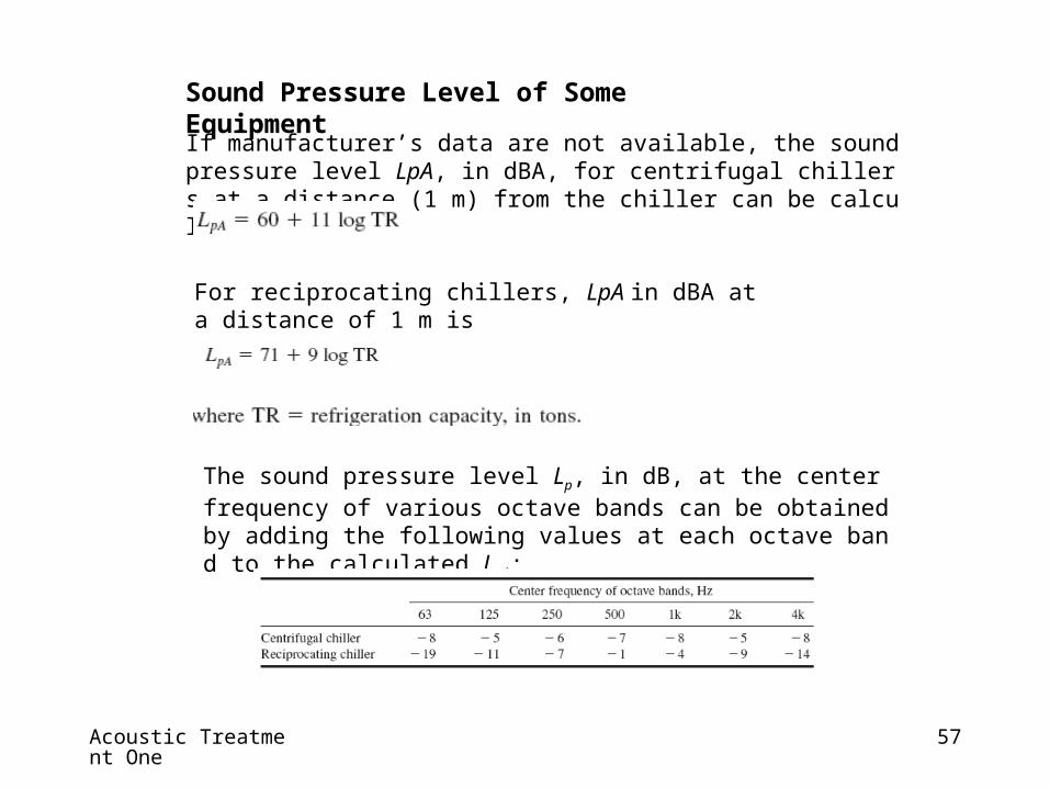
If manufacturer’s data are not available, the sound pressure level LpA, in dBA, for centrifugal chillers at a distance (1 m) from the chiller can be calculated as
For reciprocating chillers, LpA in dBA at a distance of 1 m is
The sound pressure level Lp, in dB, at the center frequency of various octave bands can be obtained by adding the following values at each octave band to the calculated LpA:
Sound Pressure Level of Some Equipment

Acoustic Treatment One
58
Circulating pumps
LpA at a distance of 1 m is
where hp power input to the pump, hp.
For fan, predicting equation was found giving very inaccurate result use manufacturer data

Acoustic Treatment One
59
A silencer is for reduction of the sound power level of a fan, an airflow noise, or other sound source transmitted along a duct-borne path or airborne path.
Rectangular and cylindrical silencers: (a) rectangular silencer and (b) cylindrical silencer.
Silencer

Acoustic Treatment One
60
Silencers used in HVAC&R systems :
Dissipative silencers.
These silencers often use face-covered or encapsulated acoustic material ( fiberglass, mineral wool, and acrylic polymers) to attenuate noise over a broad range of frequencies.
The facing material can be made of Galvanized or aluminum sheet with perforation.
Packless silencers.
There is no fibrous fill. Noise is attenuated by means of acoustically resistive perforations in the splitters. They are often made of sintered aluminum or acrylic plastics.
Reflection-dissipative silencers.
These silencers use the combined effect of sound reflection and dissipation in airflow passages of successive square elbows.
Active silencers.
These silencers produce low-frequency inverse sound waves to cancel the unwanted noise.

Acoustic Treatment One
61
• Silencers can be classified into rectangular, cylindrical, and sound-attenuating plenum according to their configuration.
• Inside the rectangular casing are a number of flat splitters, depending on the width of the silencer.
• These splitters direct the airflow into small sound-attenuating passages.
• The splitter is made from an envelope containing sound-attenuating material, such as fiberglass or mineral wool, with protected non-eroding facing.
• The thickness of a splitter is often between 25 and 100 mm.
Silencer

Acoustic Treatment One
62
• Splitters often have a round instead of a flat nose, to reduce their airflow resistance.
• A rectangular silencer is often connected with rectangular ducts or sometimes with rectangular fan intakes and discharges.
• A cylindrical silencer has an outer cylindrical jacket and an inner concentric center body.
• Both the cylindrical jacket and the center body contain sound-attenuating material and non-eroding facing.
• A cylindrical silencer is often used in conjunction with vane-axial fans and in round duct systems.
Silencer

Acoustic Treatment One
63
Characteristics of Silencers
The acoustic and aerodynamic characteristics of a silencer are mainly indicated by four parameters.
Insertion Loss.
Meaning - capacity to reduce the sound power level noise at various frequencies.
Affected by - air- flow direction (especially air velocity > 1 m/s).
A sound wave that propagates in the same direction forward flow,
Opposite to the airflow reverse flow.
Low frequencies reverse flow has a longer contact time higher IL
High frequencies, sound waves tend to refract toward the absorptive surface in a silencer under reverse flow
Large high-frequency attenuation in the forward flow and less in reverse flow.

Acoustic Treatment One
64
Typical free air ratio = 0.3 to 0.8.
The actual mean air velocity inside the airflow passages in a silencer vfree, in m/s, may be 1.25 to 3.3 times the face velocity vsil.
The face velocity of a silencer and sound-attenuating plenum is 2.5 -10 m/s.
Silencer
Acoustic Treatment One
65
Self-Noise.
This is the lower limit of sound power level, in dB, that a specific silencer can approachat various octave band center frequencies.
Pressure Drop psil.
This is the total pressure drop of airstream when it flows through a silencer.
Pressure drop psil is a function of its face velocity, free area ratio, length, and the con-figuration of the splitter or the center body.
In general, if psil > 87Pa, both vfree and airflow noise should be investigated.
Silencer

Acoustic Treatment One
66
Location of Silencers
A minimum distance Lsil kept between the upstream fan discharge outlet or other duct fittings and the silencerensure a uniform approach velocity at silencer inlet or an undisturbed discharging velocity at the silencer exit.
From the fan discharge, Lsil must be equal to or greater than the distance of one duct diameter for every 5 m/s average duct velocity.
From the fan intake, Lsil should be equal to or greater than 0.75 duct diameter for every 5 m/s average duct velocity.

Acoustic Treatment One
67
Active silencers use ducted enclosure to cancel duct-borne, low-frequency fan noise (including rumbles)
This is done by producing sound waves of equal amplitude and opposite phase.
The primary sound source is the unwanted fan noise.
The secondary sound source cancel;ing the unwanted source comprises the inverse sound waves from a loudspeaker.
Active Silencers

Acoustic Treatment One
68
Operating-Characteristics.
An active silencer consists of microphones, a microprocessor-based controller, a loudspeaker, and a ducted enclosure.
Fan noise is propagated along a duct, an input microphone measures noise and sends an electric signal proportional to the sound wave to the controller.
The microprocessor-based controller calculates the amplitude, frequency, and phase of the propagating sound and sends a cancel signal to the loudspeaker.
The loudspeaker broadcasts sound waves of the same amplitude and frequency as the unwanted noise (180° out of phase).
The destructive interference between these two sound sources results in the cancellation of the incident fan noise by the secondary source broadcasted by the loudspeaker.
The amplitude of the fan noise is reduced downstream of the loudspeaker.
An error microphone measures the residual noise optimize the performance of the active silencer.

Acoustic Treatment One
69
System Characteristics.
In an active silencer, sound energy is added to the fan noise to cancel it, whereas in a traditional passive silencer, sound energy is converted to heat and removed from the system.
Because the microphone in an active silencer cannot distinguish the fan noise and the turbulent air-flow noise, air velocity in the ducted enclosure of an active silencer not exceed 7.5 m/s.
When the duct velocity exceeds 12.5 m/s, the turbulent noise may completely mask fan noise, and the effect of an active silencer is reduced to nil.
Pressure drop of a passive silencer is often 50 to 63 Pa.
The electric energy required to produce the canceling sound is only 40 W, a substantial saving compared to a passive silencer.

Acoustic Treatment One
70
Performance.
It was found that :
Active silencer has a good sound attenuation in frequencies between 31 and 125 Hz
Duct liner provides effective sound attenuation in frequencies of 500 Hz and more
A say 2m length prefabricated silencer is effective in frequencies between 63 and 4000 Hz

Acoustic Treatment One
71
Lined Plenums