Embed Size (px)
Citation preview
ACOUSTIC SCATTERING FROM ELLIPSES BY THE MODAL
ELEMENT METHOD
Kevin L. Kreider
The University of AkronDepartment of Mathematical Sciences
Akron, Ohio 44325-4002
and
Kenneth J. Baumeister
National Aeronautics and Space AdministrationLewis Research CenterCleveland, Ohio 44135
ABSTRACT
The modal element method is used to study acoustic scattering from ellipses, which may beacoustically soft (absorbing) or hard (reflecting). Because exact solutions are available, the results provide abenchmark for algorithm performance for scattering from airfoils and similar shapes. Numerical results for
scattering from rigid ellipses are presented for a wide variety of eccentricities at moderate frequencies. Theseresults indicate that the method is practical.
INTRODUCTION
Acoustic and electromagnetic scattering from airfoils is of interest to the aerospace industry in, forexample, studies of noise abatement and identification by radar signature. The study of scattering fromcylinders and bodies embedded in circular cylinders using the modal element method was recently presented
by Baumeister and Kreider (1993a). The modal element method is a computationally efficient formulation inwhich both analytical and finite element solutions are combined. This study is concerned with scattering fromellipses using the modal element method. The elliptic geometry can be computationally efficient in manyaeronautic applications. For example, thin airfoil shapes can be more naturally embedded in an ellipse than ina circle.
The modal element method has been employed in electromagnetic and acoustic scattering and ducttransmission problems (Baumeister and Baumeister (1994), Baumeister and Kreider (1993a), Baumeister andKreider (1993b), Lee & Cendes (1987), Astley and Eversman (1981), and Chang & Mei (1976), for example).In this method, the acoustic pressure or electromagnetic field in and on the scattering body is represented byfinite elements (the finite element solution), while the field is represented by an eigenfunction expansionaway from the body (the modal solution). The two solution forms are coupled through an interface condition.
The purpose of this paper is to present the results of the study of acoustic scattering from ellipsesusing an elliptic interface rather than a circular one. The modal element method using an elliptic interfacecan be used effectively to study scattering from airfoil shapes for two reasons. First, if the far field resultsmatch the exact solution for hard ellipses of high eccentricity, it can be inferred that the method can beapplied to scattering from a similar shape, such as an airfoil. Second, airfoils can be more efficientlyembedded in an ellipse than in a circle, which decreases the size of the finite element domain, savingcomputation time and lessening computer memory requirements. For example, a reduction of grid size by 10yields a savings in the global matrix size of 100.
There have been many recent studies of scattering from ellipses and more complicated shapes using
other analytical methods; among them are Kim (1991), Jin and Liepa (1988), and Rojas (1988). The presentwork adds to these studies by allowing more flexibility in setting absorbing material around the surface of theellipse.
https://ntrs.nasa.gov/search.jsp?R=19950022980 2018-08-31T04:04:58+00:00Z

Thenumerical results presented here are for scattering from hard ellipses. The modal element methodcould also be used t0r scattering from soft ellipses, with the modifications mentioned under Results.
SOLUTION METHOD
The goal here is to compute numerically the acoustic scattering of a plane wave, travelling in the +xdirection, that strikes an ellipse. The spatial domain is divided into two subdomains, the finite elementdomain, which contains the body, and the homogeneous domain, which surrounds the body and extends toinfinity (fig. 1). Linear triangular elements are used in the finite element domain to calculate the pressure atthe nodes (the finite element solution). In the homogeneous domain, an eigenfunction expansion withunknown modal coefficients represents the acoustic pressure (the modal solution). The two solution forms are
coupled by imposing continuity on the pressure and velocity at the elliptical interface between the twosubdomains. This coupling results in a single matrix equation in which the eigenfunction coefficients and thepressures at the finite element nodes are calculated simultaneously, yielding a global representation of theacoustic field.
GEOMETRICAL MODEL
For the numerical studies done here, the scattering ellipse is taken to be rigid; in this case, it can berepresented by a thin ring of finite elements as shown in figure 2. The elliptic co-ordinate system used is shownin figure 3. The variables are standard:
dx =--coshu cosv
2
y = dcoshu sinv (1)2
Z=Z
= coshu, 11= cosy
In (u,v) co-ordinates, u is the radial and v is the angular component; in (_,rl) co-ordinates, _ is the radial and
rl is the angular component. The semi-major and semi-minor axes are denoted a and b, respectively, andd = 2 (a2-b2) 112 is the interfocal distance. The major axis is oriented along the x axis. The eccentricity of the
ellipse is defined as
d 1e_u_m.
2a(2)
GOVERNING EQUATION
Acoustic propagation in two dimensional space can be modeled by the continuity, momentum, andstate linearized gas dynamic equations in the absence of flow. For harmonic pressure propagation in aninhomogeneous material, the following dimensionless wave equation applies:

,:o. (3)
The harmonic time dependence e-ic°t has been factored out. In analogy with electromagnetic scattering, e isthe acoustic "permittivity", IXis the acoustic "permeability" and co is the dimensionless frequency. Details ofthese acoustic properties can be found in Baumeister and Dahl (1987). The wave number is
(4)
At the interface between the finite element region and the analytic region, continuity is imposed on
the pressure and velocity. The radiation boundary condition at infinity is automatically satisfied by theeigenfunction expansion introduced in the next section.
ANALYTIC SOLUTION
In the homogeneous domain, an exact eigenfunction expansion can be derived from equation (3) by
separation of variables. In elliptic co-ordinates, the eigenfunctions are the Mathieu functions. A plane wavewith incident angle _0 that strikes the rigid ellipse generates a pressure field written as (Bowman, et al.,
(1969), pg. 146, equation (3.76))
00 I Re(lm)'(c'_l) Re(3m)(C'_) Sem(C'C°S¢°) Sem(C'lq)Pa = pi + pS =eik(xcos% +ysin_o)_._7_ Z im N_e) Re(3m)'(C'_l )
m--O k
1 R°(lm)'(C'{l) _"_(3)¢c _ So tc cost. "_ )+ (o) _ "win t ,"_/ rn', ' "ro"SOm(C'TI) (5)
N m Ro m (C,_l) )
pi is the incident plane wave, pS is the scattered field, c = kd/2 and _0 is measured counterclockwise from the
+x axis. _1 represents the surface of the ellipse, while the observation point (_,rl) is exterior to the ellipse. The
even and odd radial Mathieu functions of the firstt t_em ' tC°m ] and third kinds are analogous,
respectively, to the Bessel functions Jm and the Hankel function of the first kind H_ ) for polar co-ordinates.
The even and odd angular Mathieu functions (Se m, So m) are analogous to the cosine and sine functions,
respectively, in polar co-ordinates. The normalization factors, N(me) and N(m°) are defined by Stratton (1941,
equations (18) and (19) pg. 376).If the incident angle _0 is set to 0, equation (5) simplifies to
m_o'ml 1 Re(Im)'(C'_l) Re(3m)(c,{)Sem(C, lq))Pa = pi -I- pS =eikX --_-87C = l -N_me) Re(3m),(C,_l)
(6)
This exact solution (eq. (5) or (6)) is used to validate the modal element solution. In general, the
scattered field is represented by

M¢o a - 1
pS E + (3) e + + (3)= AmRe m (c,_)S m(C,'q) BmRO m (c,_)SOm(C,'q)
m=O
(7)
where the unknown coefficients A+m and B+m are to be determined by solving the global matrix equation. If the
incident angle 0p0= 0, then the odd terms vanish (B+= = 0). If the incident angle is nonzero, or if the scatterer
is not symmetric about the x axis, then the odd terms must be included.Formulas to estimate the number of modes Mcoa needed for convergence for scattering from circles
can be found in Baumeister and Kreider (1993a). As the eccentricity of the ellipse increases, this numberincreases to a limit of roughly twice the value for circles.
The numerical calculation of Mathieu functions is challenging. There are several sets of acceptednotation and several types of normalization of the functions. The functions are represented as a series, eachterm of which depends on an eigenvalue that must be calculated by solving an equation involving a continuedfraction. Details of the theory of Mathieu functions may be found in Magnus, et al., (1966). Details of thenumerical calculation of Mathieu functions may be found in Blanch (1964), Canosa (1971), Clemm (1969),Hirsch (1972) and Toyama and Shogen (1984). Clemm's algorithm, as improved by Hirsch, was adapted foruse in this study.
INTERFACE CONDITIONS
At the interface S between the finite element domain and the homogeneous domain, both pressure andvelocity are continuous (Temkin, 1981, pg. 80). The continuity of pressure
Pls÷ - Pis- = o (8)
is expressed numerically by an integral weighting procedure, so the continuity of pressure at the interface is
represented by the set of equations
0=2X
_S Wm*[Pa-Plds=O %* =Sem*(C"q)'
0=0
m* = 0,1,2 ..... Mcoef - 1 (9)
There must be one weight equation for each unknown in eqn (7); if odd terms are included thenadditional weights Som(c,rl) are introduced.
The choice of weight functions is crucial, since, as discussed under Results, the solution is quitesensitive to the weights used. The natural choice is to use Wrn = Sere, since the angular Mathieu functions are
orthogonal over the surface of the ellipse (Abramowitz and Stegun (1972), section 20.5). However, this choicedoes not give perfect results, so that possibly a better choice of weights could be found, although after someexperimentation, it seems unlikely.
The integration element ds in equation (9) is given by
b2 [ e4 cos 2 0sin 2 01ds 2 = r2d02 + dr 2 = 14
l_e2 cos2 0 _ _-_e2_os-_0)2 ] d02 (10)
where the radius at any point on the ellipse is
4

r2 = b 21 - e 2 cos 2 0'
(11)
The discretization of these equations, as well as the imposition of the continuity of the pressure
gradient across S, is done as in Baumeister and Kreider (1993a).
FINITE ELEMENT SOLUTION
The finite element domain is divided into triangular elements with unknown acoustic pressure at the
nodes. It is assumed that all material properties are constant in each element. The setup of the global matrixfollows the derivation in Baumeister and Kreider (1993a).
The weak finite element formulation of equation (3) contains a surface integral with the normalderivative of p, which is equated to the normal derivative of Pa. The normal derivative of the scattered field
pS = _ M_f-la+ l_,,(3)tu'_ Sere(v) (12)
requires some explanation. Notice that the notation for the arguments of the Mathieu functions has beenstreamlined, and uses (u,v) co-ordinates instead of (_,rl), to be consistent with the computer code. It isconvenient to write the normal derivative in terms of rectangular co-ordinates
= cos 1_+ sin 139n
(13)
where 13 is the angle between the normal to the surface and the horizontal. The code can provide the values of
dps/du and dps/dv, so by writing
Ox 3u Ox Ov Ox
_y _u ¢_y _v _y
(14)
it remains only to determine du/dx, du/dy, dv/dx and dv/dy. This is done by differentiating the transformation
equations (1) each with respect to x and y to obtain
a 0 °= 0 A 0
B 0 A
3x I
a±!_y I
3v I
3x I
_v I-- i
_,_y)
(15)
where A = d sinh u cos v and B = d cosh u sin v. This 4 by 4 block matrix is easily inverted to give the desired
quantities. Substituting them into equation (14) and then equation (13) gives the final form of the normalderivative

OPs_(cos_Jsinhucosv+sinfjcoshu sinv_'' ++ <3) _"On-_ d(sinh2u c_s2v _-c--osh_u s_n2_)"_ _-'AmIRem (u))Sere(v)
(-COS_ coshu sinv +_ sin_ si__.uu cosv./_--_ _+n (3)..
+L
(16)
where the primes signify derivatives with respect to the arguments.
RESULTS
Three examples were chosen to illustrate the behavior of the modal element method when applied toscattering from ellipses. In Example 1, the scattered pressure in the near field is shown for a range ofeccentricities. Example 2 shows the near and far scattered fields for a higher frequency. In Example 3, thefinite element solution is compared to the modal solution at the surface of the ellipse.
In each of the examples, the ellipse is defined with semi-major axis a = 1 (oriented along the x axis),and the semi-minor axis b varies between 0 and 1 to change the eccentricity. Near and far field polar plots(Examples 1 and 2) are taken on circles of the indicated radius to conform to usual far field results, while thesurface plots of Example 3 are taken on the surface of the ellipse. The incident plane wave travels in the +xdirection with a fixed frequency.
In the examples, the ellipse is taken to be hard, which is simulated numerically through an impedancemismatch induced by setting e = I - 1019i and ix = 1 for each internal finite element. This feature allowsgreater flexibility in the numerical implementation of the method, because penetrable or coated rigid bodiesmay be studied with only slight modifications to the computer code, mainly in grid generation. For penetrablebodies, the internal grid is more extensive, while for coated bodies, several rings in the coating region may beneeded.
For examples with wave number k = 1, there are 264 grid points and 11 modal terms used, while forthose with wave number k = 5, there are 384 grid points and 16 modal terms used. For all examples, theincident angle 00 is set to 0 and the thickness of the ring (fig. 2) is set to 0.001.
Example 1--Varying The Eccentricity Of The Ellipse.--The incident plane wave has wave numberk = 1. Figures 4(a) to (d) show the modal solution for the scattered pressure field in the near field for a set ofellipses of increasing eccentricity. The exact solutions are represented by solid lines. As seen in figure 4, theerrors increase slightly as b gets smaller (thinner ellipse). However, even for the most elongated scatterer, themethod successfully calculates the field. For this reason, it is believed that the calculation of the far fieldpressure field from a realistic airfoil shape would be trustworthy.
Example 2--Near And Far Fields At Higher Frequeney.--The incident plane wave has wavenumber k = 5 with semi-major axis a = 1 and semi-minor axis b = 0.5. Figures 5(a) to (d)show polar plots ofthe modal solution around circles of increasing radius. The exact solutions are represented by solid lines. It is
clear that the solution improves farther from the scatterer, which is a consequence of the fact that theconvergence properties of equation (7) improve as _ (or u) increases. If only the far field is desired, arelatively coarse grid and fewer modal terms can be used. In the near field, more terms are required to obtainthe same level of accuracy (Baumeister and Kreider 1993a, fig 4). Of course, as the frequency increases, afiner finite element grid and more modal terms must be used, leading to a larger global matrix and longercomputation times.
Example 3---Comparison Of Finite Element And Modal Solutions.--The incident plane wave haswave number k = 1 with semi-major axis a = 1 and semi-minor axis b = 0.8. Figures 6(a) and (b) show thescattered pressure field at the surface of the ellipse based on the finite element (fig. 6(a)) and the modal(fig. 6(b)), solutions. The exact solutions are represented by solid lines. Previously, as has been shown in
figures 4 and 5, the modal element solution has been shown to be very accurate in the far field. Now, as seenin figure 6(b), the modal element solution is quite good in the near field on the surface of the ellipse.
6
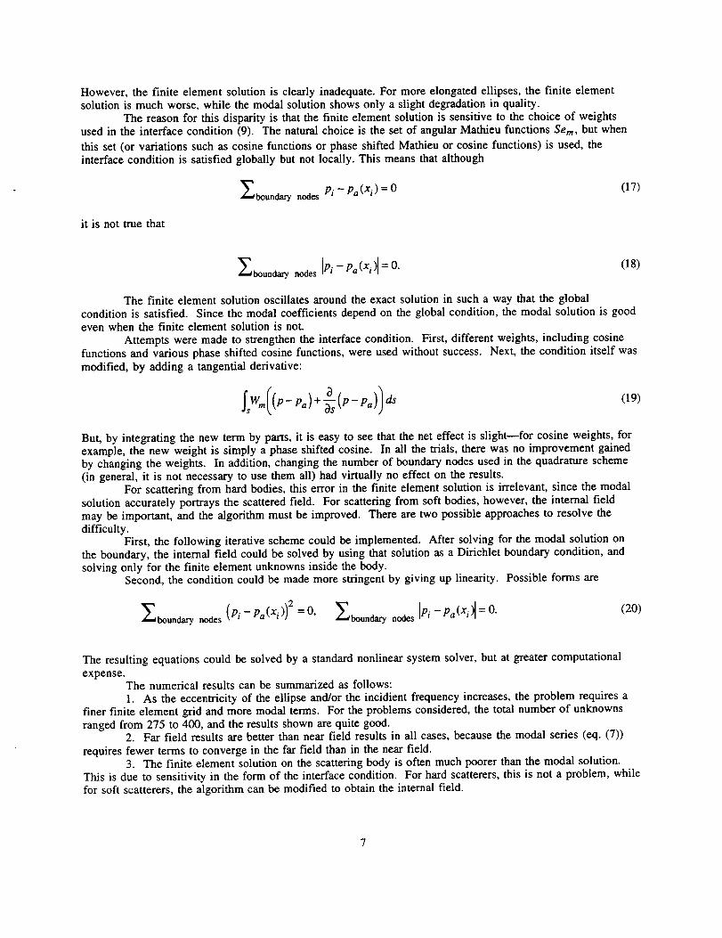
However,thefiniteelementsolutionis clearlyinadequate.Formoreelongatedellipses,thefiniteelementsolutionismuchworse,whilethemodalsolutionshowsonlyaslightdegradationinquality.
Thereasonfor thisdisparityis thatthefiniteelementsolutionissensitiveto thechoiceof weightsusedin theinterfacecondition(9). Thenaturalchoiceis thesetof angularMathieufunctionsSere, but when
this set (or variations such as cosine functions or phase shifted Mathieu or cosine functions) is used, theinterface condition is satisfied globally but not locally. This means that although
_boundary nodes Pi - Pa (xi) = 0(17)
it is not true that
_boundary nodes IPi -- Pa(Xi) = O.(18)
The finite element solution oscillates around the exact solution in such a way that the globalcondition is satisfied. Since the modal coefficients depend on the global condition, the modal solution is goodeven when the finite element solution is not.
Attempts were made to strengthen the interface condition. First, different weights, including cosinefunctions and various phase shifted cosine functions, were used without success. Next, the condition itself was
modified, by adding a tangential derivative:
_sWml(P-Pa)'t'_'_(P-Pa)) dS(19)
But, by integrating the new term by parts, it is easy to see that the net effect is slight--for cosine weights, forexample, the new weight is simply a phase shifted cosine. In all the trials, there was no improvement gainedby changing the weights. In addition, changing the number of boundary nodes used in the quadrature scheme(in general, it is not necessary to use them all) had virtually no effect on the results.
For scattering from hard bodies, this error in the finite element solution is irrelevant, since the modalsolution accurately portrays the scattered field. For scattering from soft bodies, however, the internal field
may be important, and the algorithm must be improved. There are two possible approaches to resolve thedifficulty.
First, the following iterative scheme could be implemented. After solving for the modal solution onthe boundary, the internal field could be solved by using that solution as a Dirichlet boundary condition, and
solving only for the finite element unknowns inside the body.Second, the condition could be made more stringent by giving up linearity. Possible forms are
_boundary nodes (Pi- Pa(Xi)) 2 =0, _boundary nodes Pi - Pa(Xi ) = O.(20)
The resulting equations could be solved by a standard nonlinear system solver, but at greater computational
expense.The numerical results can be summarized as follows:
1. As the eccentricity of the ellipse and/or the incidient frequency increases, the problem requires afiner finite element grid and more modal terms. For the problems considered, the total number of unknownsranged from 275 to 400, and the results shown are quite good.
2. Far field results are better than near field results in all cases, because the modal series (eq. (7))
requires fewer terms to converge in the far field than in the near field.3. The finite element solution on the scattering body is often much poorer than the modal solution.
This is due to sensitivity in the form of the interface condition. For hard scatterers, this is not a problem, whilefor soft scatterers, the algorithm can be modified to obtain the internal field.

CONCLUSION
A studyof acoustic scattering by ellipses using the modal element method has been presented. Themethod yields acceptable numerical results for scattering from hard ellipses of any eccentricity for a range ofmoderate frequencies. For soft ellipses, the method must be modified to obtain the internal field. Thenumerical cases presented are used as validation for the method, and indicate that when applied to scatteringfrom realistic airfoil shapes, the modal element method should yield accurate results. In addition, the airfoilcan be embedded in an ellipse rather than a circle, decreasing the size of the finite element grid, and hencereducing the computing requirements for the problem.
REFERENCES
Abramowitz, M. and Stegun, I., 1972, "Handbook of Mathematical Functions," Dover Press, New York.
Astley, R.J., and Eversman, W., 1981, "Acoustic Transmission in Non-Uniform Ducts with Mean Flow, Part H:The Finite Element Method," Journal of Sound and Vibration, Vol. 74, pp. 103-121.
Baumeister, K.J. and Baumeister, J.F., "Modal Element Method for Potential Flow in Non-Uniform Duct:Combining Closed Form Analysis With CFD," AIAA Paper 94--0813.
Baumeister, K.J. and Dahl, M.D., 1987, "A finite element model for wave propagation in an inhomogeneousmaterial including experimental validation," AIAA Paper 87-2741 (also NASA TM-100149).
Baumeister, K.J. and Kreider, K.L., 1993a, "Modal Element Method for Scattering and Absorbing of Sound byTwo-Dimensional Bodies," Journal of Vibration and Acoustics, Vol. 115, pp. 314-323.
Baumeister, K.J. and Kreider, K.L., 1993b, "Modal Ring Method for the Scattering of Sound," NASATM-106342.
Bowman, J.J., Senior, T.B.A. and Uslenghi, P.L.E., 1969, "Electromagnetic and Acoustic Scattering by SimpleShapes," North-Holland Publishing Company, Amsterdam.
Blanch, G., 1964, "Numerical Evaluation of Continued Fractions," SIAM Review, pp. 383-421.
Canosa, J., 1971, "Numerical Solution of Mathieu's Equation," Journal of Computational Physics, Vol. 7,
pp. 255-272.
Chang, S.K. and Mei, K.K., 1976, "Application of the Unimoment Method to Electromagnetic Scattering ofDielectric Cylinders," IEEE Transactions on Antennas and Propagation, pp. 35-42.
Clemm, D., 1969, "Characteristic Values and Associated Solutions of Mathieu's Differential Equation,"Communications of the ACM, Vol. 12, pp. 399-407.
Hirsch, C., 1972, "Computation of Individual Characteristic Values and Associated Solutions of Mathieu'sEquation," Vrije Universiteit Te Brussel, Report VUB-STR-1.
Jin, J.M. and Liepa, V., 1988, "Application of Hybrid Finite Element Method to Electromagnetic Scatteringfrom Coated Cylinders," IEEE Transactions on Antennas and Propagation, Vol. 36, pp. 50--54.
Kim, C.S., 1991, "Scattering of an Obliquely Incident Wave by a Coated Elliptical Conducting Cylinder,"Journal of Electromagnetic Waves and Applications, Vol. 5, pp. 1169-I 186.
Lee, Jin-Fa and Cendes, Z.J., 1987, "The Transfinite Element Method for Computing Electromagnetic
Scattering From Arbitrary Lossy Cylinders," AP-S International Symposium, paper AP03-5, Blacksburg,Virginia.

Magnus,W.,Operhettinger,F.andSoni,R.P.,1966,"FormulasandTheoremsfortheSpecialFunctionsofMathematicalPhysics,"Springer-Verlag,NewYork.
Rojas,R., 1988,"ScatteringbyanInhomogeneousDielectric/FerriteCylinderof ArbitraryCross-SectionShape- ObliqueIncidenceCase,"IEEETransactionsonAntennasandPropagation,Vol.36,pp.238-246.
Stratton,J.A.,1941,"ElectromagneticTheory,"McGraw-Hill,NewYork.
Temkin,S.,1981,"Elementsof Acoustics,"JohnWileyandSons,NewYork.
Toyama,N.andShogen,K.,1984,"MathieuFunctionforGivenParametersandArguments,"IEEETransactionsonAntennasandPropagation,Vol.AP-32,pp.537-539.

Homogeneousdomain
In_cid_t
plane wave
/Interfacial /
boundary S --_
Figure 1 .inFinite element grid system.
Homogeneousdomain
plane wave___Z__ _I
Interfacial _ iboundary S --_ L_ Finite element
domainc = 1-1019i
p. = 1.0
Figure 2.inFinite element ring grid system for rigid bodies.
Y
v= 2 _r_ 2
v _ ! _ I u=C
v.__d
I
= _(x, y)
v=_
d
I
Figure 3.--Elliptic cylindrical geometry.
10

Exact analysis, ABS P[] Numerical solution, ABS P
0 . . 2.0
/ _ \ \ _.,,_l J J/ / Pressure / Pressure
mplitude _/_mplitude
. @ .
0 0
I \_ \ _ :! I ,_u,e 1 \ _\ \I_/' I/ l ,,e_u,e
Figure 4.BNear field polar plot of total acoustic pressure around a rigid ellipse subjected to plane wave impingement recon-structed from calculated modal coefficients at specified b (k = 1, a = 1, r = 1.0). (a) b = 1.0. (b) b = 0.8. (c) b = 0.5. (d) b = 0.2.
1!

Exactanalysis,ABSP[] Numericalsolution,ABSP
0 DI
Figure 5._Polar plot of total acoustic pressure around a rigid ellipse subjected to plane wave impingement reconstructed from
calculated modal coefficients at specified radius r (k = 5, a = 1, b = 0.5). (a) r = 1. (b) r = 3. (c) r = 5. (d) r = 10.
]2

Exactanalysis,ABSPNumericalsolution,ABSP
o [] o
i° ee
(a) _ Co)
Figure 6.--Total pressure amplitude on the surface of an ellipse subject to plane wave scattering (k = 1, b = 0.8). (a) Finite
element solution. (b) Modal solution.
]3

FormApprovedREPORT DOCUMENTATION PAGE OMBNo.0704-0188
Pul_i¢ rspo_ burden for this colbc_on ot kzformEionis mtl .mawd.to .average 1 Iw. I_..ms. I_. I_udlng the time for ..reviewS..In_'u¢_, _ ¢l_i_.klg_ _umm,,
collectiond Infommitlon,incluolngsuggestionslot"reducing mls ouroen, to Wasnlrtl_onHeaoquaners _ u fecu_m " mejm.arrr_t_n.__U_l_lm_. " =a_Mepo_,___1_1o 4enmsonDavis HIglwmy, _ 1204, AdbOton, VA 22202-4302, and to the Offlm af Management and BudgeLPapemom Heaucuon mole= (u,,u4-u Ueh wasn gton, u_ zuouu.
1. AGENCY USE ONLY (Leave blank) 2. REPORT DATE 3. REPORT TYPE AND DATES COVERED
Jm-,c1995 TechnicalMcmora_mn
4. TITLE AND SUBTITLE 5. FUNDING NUMBERS
AcousticScaUcringFrom Ellipsesby tic Modal ElementMethod
e. AUTt_R(S)
Kevin L. Kreider and Kenneth J. Baumeister
7. PER_ ORGANIZATION NAME(S) AND ADDRESS(ES)
National Aeronautics and Space AdministrationLewis Research Center
Cleveland, Ohio 44135-3191
9. SPONSORING/MONrrORING AGENCY NAME(S) AND ADDRESS(ES)
National Aeronautics and Space AdminisWafionWashington, D.C. 20546-0001
WU-505---62--52
8. PERFORMING ORGANIZATIONREPORT NUMBER
E-9663
10. SPONSORING/MONITORING
AGENCY REPORT NUMBER
NASA TM-106935
11. SUPPLEMENTARY NOTES
Kevin L. Kreider, The University of Akron, Depamnent of Mathematical Sciences, Akron, Ohio 44325 and Kenneth J.Baumcister, NASA Lewis Research Center. Responsible person, Kenneth J. Baumeiste¢, organization code 2660,(216) 433-5886.
12a. DI STRIBUTIOWAVAILAB ILrrY STATEMENT
Unclassified -Unlimited
Subject Categcxy 71
This publication is available from the NASA Center for Aerospace Information, (301) 621-0390.
i12b. DISTRIBUTION CODE
13. ABSTRACT (JibJdrnutn200 words)
The modal clementmethod is usedto sludyacousticscaueringfrom ellipses, which may be aco,sfica]]y soft (absorbing)or hard (reflecting). Became exact solutionsare available,the mstdts provide a benchmarkfor algoddunpcffo_ forscattering from airfoils and similar shapes. Numerical insulinfor scattering fi'om rigid ellipses are presented for a widevariety of eccentricities at moderate frequencies. These results indicate that the method is practical.
14. SUBJECT TERMS
Finite elements; Modes; Scattering
17. SECURITY CLASSIFICATIONOF REPORT
Unclassified
18. SECURITY CLASSIFICATIONOF THIS PAGE
Unclassified
NSN 7540-01-280-5500
19. SECURITY CLASSIFICATIONOF ABSTRACT
Unclassified
lS. NUMBER OF PAGES
1516. PRICE CODE
A0320. LIMITATION OF ABSTRACT
Standard Form 298 (Rev. 2-89)
Prescribed by ANSI Sld. Z39-18296-102