Embed Size (px)
Citation preview
1
ACOUSTIC NAVIGATION FOR MOBILE ROBOTS
Critical Design Review
Josh Earley Trent Foley
Thomas Garner Chris Gonzales
CPSC 483 – Spr ing 2003
3 MAR 2003

2
Table of Contents
Introduction............................................................ pg.3
Current Design....................................................... pg.3
Changes from Proposal .......................................... pg.4
Current Design Problems ....................................... pg.5
Future Design/Implementation Issues..................... pg.7
PCB Generation ..................................................... pg.8
Robot ..................................................................... pg.8
Scheduling/Order Status......................................... pg.8
Future Plans ........................................................... pg.9

3
Introduction
Our design project is going according to plan. We have already ordered a majority of the
major parts and are working diligently on the final aspects of our design. Our parts have begun
arriving and we are beginning the testing phase. Below is on outline of our status concerning
different aspects of the design, as well as an update on our scheduling, cost, and new
implementations that differ from our original proposal.
Cur rent Design
Figure 1 illustrates our current design. We have decided to fabricate two separate printed
circuit boards: one for the microphone array itself and one for the microcontroller. This will
allow us more modularity and ease of maintenance and fabrication. The microphone array board
will consist of the 8 microphones patterned in such a way that each microphone has 45o of
coverage. Further, the board will have the resistors and capacitors that develop the output signal
for each microphone. We will route the signals to the microcontroller board via a 10-pin
connector: 8 pins for the microphone signals, 1 pin for Vcc, and 1 pin for ground. The
microcontroller prepares the microphone signal to be presented to the microprocessor of the
Mark III. This board will accept the eight microphones data into an 8:1 multiplexor that is
controlled by the Mark III’s processor. Once a microphone is selected, it will be sent to the filter
(LMF100). The filter has two inputs, one for the microphone data and one from the crystal and
4-bit counter (74LS191) circuit, which will provide 8 center frequencies through a processor
controlled 8:1 multiplexor. After the filter, the signal will be rectified and sent to the A/D

4
converter (ADC0801). This will convert the rectified signal into an 8-bit digital signal that is
sent to the processor. In all, we will use 14 interface bits on the Mark III. Six bits will be used
for the multiplexors, and eight bits will be used for the microphone signal. However, we also
have the capability to send the microphone signal to the processor in analog format, since the
Mark III has 4 analog inputs onboard that route to analog-to-digital converters.
Changes from our proposed design
The most critical changes from our proposed design is that we have decided to use a
switched-capacitor filter as opposed to the static low and high pass filters in the original design.
This will allow us to utilize an efficient bandpass filtering system which we can dynamically
control the center frequency from the processor of the Mark III. The filter that our team chose is
the LMF100 from National Semiconductor (Figure 2). It is operable with a single power supply
and offers many modes of simultaneous filtering. The LMF100 datasheet details how to
configure the device for our needs. With this change in filtering design from our proposed
design, a clock, counters, and 8:1 digital multiplexer will be additionally required. The clock
will drive the counter, so that the clock signal will be halved at each bit, granting lower
frequencies. These frequencies from the clock will then be multiplexed to be the clock input to
the LMF100 filter. The eight center frequencies are 5 kHz, 2.5 kHz, 1.25 kHz, 625 Hz, 312.5
Hz, 156.5 Hz, 78.12 Hz, and 39.06 Hz as shown in Figure 3. This will give us a broad range to
test and demonstrate the tracking abilities of our design.
Another aspect of our design that changed was that we switched microphone sampling
control from the hardwired circuit to the processor, which allows us greater flexibility in
monitoring a specific microphone. In our proposal, we constantly polled each microphone in a
5
loop based on the time specified by our clock. By using the processor we are now able to select
a certain microphone at any time.
Our original proposal also stated that we would be using the Motorola Coldfire UART.
However, we have decided to use the Mark III robot (Figure 4). It is small, expandable, and is
serial port programmable. One of the main reasons that we chose this robot is that it is much
cheaper than other robots we were considering. Also, our advisors had recommended we go
with the Mark III because many of the other design groups were using Boebots. This robot also
features both analog and digital inputs which could possible be used to bypass the need for A/D
converters in our initial design. Unlike other robots we looked at, the Mark III is programmable
in C or Java. We also purchased an upgrade for the robot that includes OOPicII+ and more
memory. The robot has already been ordered and we should receive it soon.
Lastly, we chose to have 8-bit resolution for our microphone signal as opposed to our
original proposal of 4-bit resolution. The main reason for this is due to the fact that the Mark III
gives us a more robust I/O interface.
Cur rent Design Problems
Sinusoidal Signal Rectification
In order to aid in the design of the rectifier, we modeled both a half-wave and full-wave
rectifier coupled with a low-pass filter using PSpice. We started with the simplest forms of each
of these rectifiers, tweaked resistance and capacitance values, and attempted to model the
behavior of the input signal as close to that of our microphones output. The following is an
overview of what we encountered during the process.
Two problems/questions we ran into during the simulations were:

6
1. What exactly is the behavior of the microphone signal going to resemble?
2. How can we simulate this behavior in PSpice?
For the first issue, we decided that in order to get a better idea of the signal, we would
need to physically test our microphones with an oscilloscope. We were assuming that the signal
generated would be a sinusoid around a constant dc voltage (Vref), oscillating anywhere between
ground and 2*Vref.
Concerning how to simulate this signal, we used a sinusoidal frequency modulating
voltage source and altered its parameters to test different frequencies and signal levels. This
could be a valid method depending on whether our assumptions about the microphone signal
above are correct. Otherwise, we will have to derive other methods to simulate the behavior.
Half wave rectifier
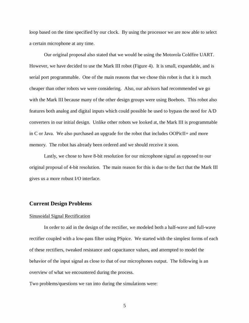
The half wave rectifier proved to be a more feasible solution over the full wave rectifier.
It is a very simple design and it accomplishes what we need. Figure 5 shows our half-wave
rectifier model. Figure 6 shows the voltage relationships between the input and output signals
with a constant 4V signal around 400 Hz. The green line is the rectified output, and the red line
is the simulated microphone input signal. Figure 7 shows the voltage relationships between the
input and output signals with a smaller input frequency of 70 Hz. The smaller frequencies
demonstrate the worst case for rectification purposes since the capacitor has more time to lose its
charge. Again, the green line is the rectified output, and the red line is the simulated microphone
input signal.

7
Microphone Sensitivity and Power Noise
After receiving our parts in, the first thing we did was connect a microphone to a simple
circuit with an oscilloscope to get an idea of the signal we would have to work with. In doing so,
we ran into two problems: microphone sensitivity and power noise.
The microphone was relatively insensitive to sound sources greater than 6-12 inches
away. In order to obtain a signal much greater than the best case noise levels, we would have to
place our sound source (in this case a computer speaker driving a single frequency) inches from
the microphone.
The second problem concerning power noise occurred when we connected an oscillator
within the same circuit using the same power supply. This introduced a large amount of noise
into the signal from the microphone that leaves the microphone signal almost unreadable.
Future Design/Implementation Issues
Concerning the microphone sensitivity, we decided to purchase a different microphone
for comparison. We chose an omnidirectional electret condenser microphone from RadioShack
(270-090). With this microphone, we received slightly better sensitivity; however, the trade-off
would be directionality.
Concerning the noise caused by the oscillator, we plan to study the noise more
thoroughly and see if we cannot eliminate it with a filter. Also, upon the successful
implementation of the dual switched capacitor, we will test for a cleaner signal.

8
PCB Generation
We have decided on the PureSoft’s EAGLE 4.0 (http://www.puresoft.co.uk/eagle/)
printed circuit board design software. This software appears to be easy to use. Powerful, and
allows for a free trial version to download. We have already generated the pcb for the
microphone array board. However, we are still working out the final details of the circuit’ s
layout on the board. Once this is accomplished, we will use the resources Prof. Gutierrez-Osuna
has provided us to get it built.
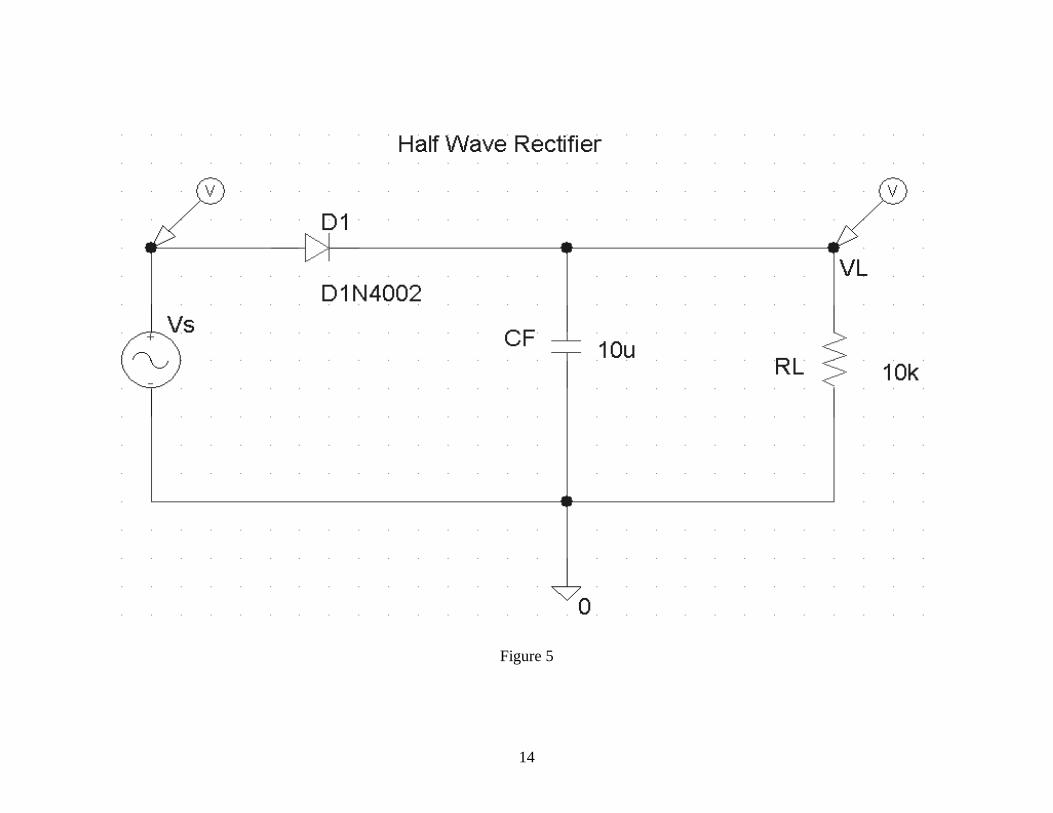
Schedule/Order Status
As far as our initial scheduling goes, we are right on time with our initial proposed work
schedule (Figure 8). We have already ordered the robot, the microphones needed for our
microphone array, some sample IC’s, the sound dampening foam, and other parts need for
construction. The only parts we have yet to order are just resistors and capacitors needed for our
filter and construction of the signal rectifier. We will get these parts either from the EE Lab on
campus or purchase them at Radio Shack. Figure 9 shows our working parts list of what we
have ordered and what we plan to get.

9
Future Plans
The signals we have observed from the microphone have been on the order of millivolts
and thus will need to be amplified. We have since ordered samples of singled powered
operational amplifies for this purpose. Our robot kit should be in shortly and we will begin
construction of the robot. This will take some time because our robot is not assembled. While
that is going on, we hope to have everything necessary for our circuit design. Time is moving
fast and we must have a completed design soon to send to be constructed.

10
Figure 1 – Current Design Diagram

11
Figure 2 – Switched Capacitor Filter

12
Figure 3

13
Figure 4 – Mark III Robot
14
Figure 5

15
Figure 6 - Voltage relationships between the input and output signals with a constant 4V signal at 400 Hz

16
Figure 7 - Voltage relationships between the input and output signals with a constant 4V signal at 70 Hz
17
Figure 8 – Updated Gantt Chart

18
Figure 9 – Working Parts List
Nomenclature Part Number Contact Quantity Price Total Electret Microphone - Panasonic
WM-65A103 www.digikey.com Navigate to online ordering and enter quantity and part number Telephone: 800-344-4539
16 1.82 29.31
8:1 Analog Mux
MC74LVX4051D www.onsemi.com (Ordered already)
5 Free samples
0.00
2:1 Analog Mux
NLAS1053US www.onsemi.com (Ordered already)
5 Free samples
0.00
Dynamat Sound Dampening Sheet - Dynamat Original Speaker Kit
10115 www.dynamat.com (Follow online store link and look for part number)
1 15.00 15.00
Analog-Digital Converter
ADC0801 www.national.com (Ordered already)
5 Free samples
0.00
Switched Filter
LMF100 www.national.com 5 Free samples
0.00
Mark 3 (OOPEC)
Junun.org 98.00 98.00
OOPEC 2+ upgrade
Junun.org 30.00 30.00
Diode D1N4002 16 Capacitor 1uF 5 Resistors 20kOhm 5