Embed Size (px)
Citation preview

Änderungen vorbehalten – Tilman Betz 02.99 – Application Note1GA39_0D
Products: Audio Analyzer UPL Digital Radiocommunication Tester CMD
Acoustic Measurements on GSM Mobile Phoneswith Audio Analyzer UPL and
Digital Radiocommunication Tester CMD
Application NoteThis application note describes test methods for commercial GSM mobiles which yield results comparable
with those of a type-approval test.

Acoustic Measurements on GSM Mobile Phones
1GA39_0D 2 Rohde & Schwarz
Contents
1 Introduction............................................................................................3
2 Preparation and Start of Application Software...................................3Required Measuring Instruments and Accessories............................3Installing the Software ........................................................................5Test Setup ..........................................................................................6Starting the Application Software .......................................................6Configuring the Application.................................................................7Setup Conversion for Firmware Updates ...........................................7
3 Operating Concept ................................................................................8
4 Measurements .......................................................................................9General...............................................................................................9Notes on Individual Measurements ..................................................10Sending Frequency Response and Loudness Rating ......................11
Sending Frequency Response ....................................................11Sending Loudness Rating ...........................................................12
Receiving Frequency Response and Loudness Rating....................13Receiving Frequency Response .................................................13Receiving Loudness Rating.........................................................13
Sidetone Masking Rating STMR ......................................................14Listener Sidetone Rating LSTR........................................................15Echo Loss.........................................................................................16Stability Margin .................................................................................17Sending Distortion ............................................................................17Receiving Distortion..........................................................................18Idle channel noise sending ...............................................................19Idle channel noise receiving .............................................................19
5 Calibration Routines ...........................................................................20Microphone Calibration.....................................................................20Calibration of Artificial Mouth............................................................21Calibration of Voice Coder Loop.......................................................22Adjustment Routine for Sending Loudness Rating using a ReferenceMobile ...............................................................................................22Adjustment Routine for Receiving Loudness Rating using aReference Mobile .............................................................................23
6 Processing of Measurement Results ................................................24Printing, Storing and Display of Measurement Results ....................24
7 Terminating the Application ...............................................................26
8 Ordering information...........................................................................26

Acoustic Measurements on GSM Mobile Phones
1GA39_0D 3 Rohde & Schwarz
1 Introduction
The acoustic transmission and reproduction quality of a mobile phone is itsmost important characteristic in every-day use. The most visually appealingdesign or a wonderfully sophisticated means of operation are not much use,when the operator user hardly understand what is being said at the otherend.
Instruments and procedures for measuring acoustic characteristics aretherefore essential tools for determining the quality and suitability of a mobile.
The special Audio Analyzer UPL16 was developed for acoustic measurementsfor the type approval of GSM mobiles. It performs all audio measurements inline with chapter 30 of GSM 11.10 on special test mobiles which are providedwith a digital audio interface (DAI).
There is however great interest in testing mobiles without a DAI. Tradejournals, consumer test institutes, or GSM network operators areparticularly interested in measuring and comparing acoustic characteristicsof commercial mobiles. Network operators, for instance, must be able tocheck customer complaints or test the quality of supplied phones. A highlyaccurate test method is also required in the quality assurance ofcommercial mobiles and for sampling inspection in production.
Mobile Phone Test UPL-B8 of Audio Analyzer UPL is now available forthese applications. With the aid of this option all the necessary audiomeasurements can be performed on conventional GSM mobiles without theDAI interface.
2 Preparation
Required Measuring Instruments and Accessories
The Audio Analyzer UPL with the following options is required :
• Extended Analysis Functions UPL-B6
• Universal Sequence Controller UPL-B10
• Mobile Phone Test UPL-B8
The GSM test mobile is driven by CMD Digital Radiocommunication Testervia the RF interface. CMD simulates a base station for the mobile so that acall can be set up. Depending on the required GSM band, CMD 52, CMD55or CMD65 is used. The selected CMD must be equipped with the Real-Time Speech Coder/Decoder option CMD-B5.
Acoustic devices such as an artificial mouth, artificial ear and otheraccessories, are also required for the measurements. The followingequipment from Brüel & Kjaer or G.R.A.S. is normally used:
Acoustic Measurements on GSM Mobile Phones
1GA39_0D 4 Rohde & Schwarz
Device Description Type
Telephone Test Head Device for fixing the DUT in theprescribed position
B&K 4602B
Ear Simulator <Measuring microphone withadapters for connection to the earpiece of the DUT
B&K 4185 (type 1)
Artificial Mouth Special loudspeaker for simulationof the mouth
B&K 4227
Acoustic Calibrator Sound level calibrator for measuringmicrophone
B&K 4231
Microphone Power Supply Power supply and preamplifier forthe measuring microphone
B&K 2690A0S2
or G.R.A.S. XYZ
Note: With the amplifier set to 0 dB, the microphone power supplyB&K 2690A0S2 produces too much noise for measuring idlenoise and distortion. It is therefore advisable to set a gain of atleast 20 dB. A low-noise power supply such as XYZ fromG.R.A.S is preferable.
Adapter Set UPL-Z1 using commercial BNC cables is recommended forconnecting the CMD accessories to Audio Analyzer UPL.
A cable a with BNC connector and a special angled banana plug is requiredfor connecting the artificial mouth, as the space between the mouthconnector and the test rack is too small for common banana plugs.
The transformer supplied with option UPL-B8 is connected betweengenerator output 1 of Audio Analyzer UPL and the connector of the artificialmouth. The transformer matches the impedance of the loudspeaker in theartificial mouth to that of the UPL’s generator . Without this transformer theavailable power is too low for driving the artificial mouth.
Alternatively an amplifier could be connected between generator output andmouth instead of the transformer.
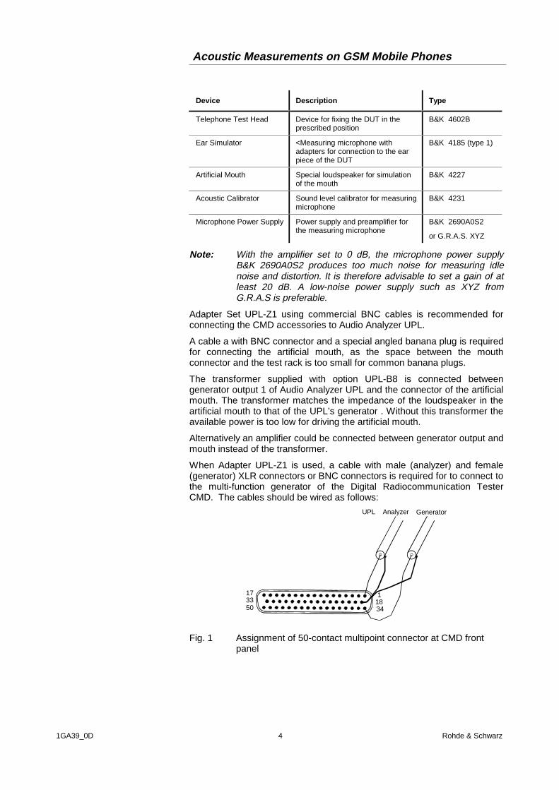
When Adapter UPL-Z1 is used, a cable with male (analyzer) and female(generator) XLR connectors or BNC connectors is required for to connect tothe multi-function generator of the Digital Radiocommunication TesterCMD. The cables should be wired as follows:
1171834
3350
UPL Analyzer Generator
Fig. 1 Assignment of 50-contact multipoint connector at CMD frontpanel

Acoustic Measurements on GSM Mobile Phones
1GA39_0D 5 Rohde & Schwarz
An external PC keyboard must also be connected to the UPL (large DINconnector). A driver for country-specific keyboards can be defined in theC:\UPL\USERKEYB.BAT file, see the UPL manual.
The BASIC program required for automatic sequence control and the filesfor generating the artificial voice are on the three floppies supplied withoption UPL-B8. The audio analyzer should meet the following firmwarerequirements:
• UPL firmware version 1.40 or higher
• Extended Analysis Functions option UPL-B6 installed
• Universal Sequence Controller option UPL-B10 installed
• Mobile Phone Test option UPL-B8 installed(will be done automatically during the installation of the software)
• UPL configured with 64 Kbyte program memory and 32 Kbyte data memoryfor automatic sequence control (using configuration tool UPLSET setting 3).
Installing the Software
The application software be installed with the aid of the PHONINST.BATinstallation program on program floppy 1. The installation number of theoptional Mobile Phone Test UPL-B8 must be known.
Caution: The software can only be installed on the specified AudioAnalyzer UPL with matching serial number.
À Quit the measurement software by pressing the SYSTEM key on theinstrument or Ctrl + F9 on the keyboard
À Insert floppy No. 1
À Select floppy disk drive (enter A:)
À Call the installation program (enter PHONINST)You are requested to enter the installation number of option UPL-B8
À Enter the installation number supplied with option UPL-B8. If the numberdoes not match the serial number of the UPL, the installation is aborted.
À Insert floppy No. 2 when asked and press any key
À Insert floppy No. 3 when asked and press any key
À Return to UPL program (enter C:\UPL)The PHONINST program creates the C:\PHONETST directory in the audioanalyzer (if it is not already available) and copies the BASIC program, theartificial voice and all setups and files required for the application into thisdirectory.

Acoustic Measurements on GSM Mobile Phones
1GA39_0D 6 Rohde & Schwarz
Test Setup
C ON TROL
ST AR T SINGLE C ON T H CO PY SYSTE M OUT PUT LOCALS TOP OFF REM
D ATA / PAN EL EDIT C URS OR / VA RIATION
OPTION S SHOW I/O ENTE R
D IS PLAY GRA PH CAN CEL
ST ATUS FILE B ACK SP
GEN A NLR FILTER SELEC T
ANALOG
GENE RAT OR A NALYZER
1 2
GE NOVLD
DIGITAL AU DIO
U NBA LOU T PU T
OPTICA L
BAL
INPU TU NBA L OPTICA L
BAL
POW ER
AUDIO ANALYZER 10 Hz ... 110 kHz UPL..
7
4 5 6
8 9
5 71
0 .+
/ -
21
35 V RMS / 100 V PK
.
8 97
5 64
21
. -0E F
PROBE ONSTANDBY
D IGITA L R A D IOC OM MU N IC ATIO N TES TE R CMD..
CLEAROFF
ENTERON
VAR
50 Ω50 Ω
RF IN/OUT RF IN 2 RF OUT 2 AF GENOUTPUT
AF VOLTMINPUT
MULTIFUNCTION
STOPBREAK
STARTCONT
MEMORY CARDDATA
MADE IN GERMANY
HARDCOPY
MEMCARD
SAVE RECALL RESET
CONF IG
LOCAL
ILLUM USERBACKSPACE
KEYHELP
3
MHz AmV%
kHz BµVW
Hz CtimedBµV
dB DdB mrad/°
MENUHOME
MENUUP
VOLU ME I VDC DC
CON TRA ST 10 A MAX 30 V MAX
1050.9008...
50 Ω
MicrophoneSupply
Transformer
art ear
art mouth
RF to Mobile
Fig. 2 Test setup and connection of external components
Starting the Application Software
The application program is executed by the automatic sequence control.The audio analyzer is switched to automatic sequence control using the F3key (on the external keyboard).
The logging function is switched off; check set "logging off" is displayed atthe bottom right of the screen; toggle logging on and off with F2. With thelogging function on, all commands entered in the manual mode would beappended to the program and so use up memory.
The application programs are called from path C:\PHONETST in order tofind all the required program routines and setups. The path can be changedin any of the following ways:
• in the manual mode with the "Working Dir" command in the FILE panel
• by calling one of the setups required for measurements on the mobile
• in the automatic sequence control mode with the BASIC command lineUPL OUT "MMEM:CDIR ’C:\PHONETST"
• under BASIC with the SHELL command by entering CD\PHONETST andpressing ENTER
• at DOS level by entering CD\PHONETST.
Acoustic Measurements on GSM Mobile Phones
1GA39_0D 7 Rohde & Schwarz
Program floppy 1 contains the BASIC program GSM_TST.BAS formeasurements on GSM mobiles. It is loaded and started by entering:
1. LOAD"GSM_TST"
2. RUN
The softkeys displayed at the bottom of the screen in the automaticsequence control mode can be used instead.
Configuring the Application
"Default-Printer" is factory set in the OPTION panel. This means that theprinter configuration does not depend on the setup, the printer last used bythe audio analyzer remains configured. New settings need not therefore bemade by the user. It is useful to select the desired printout with type, format,and scaling in manual mode before the program is started. All subsequentprintouts triggered with the hardcopy key will then be printed with thesesettings.
IMPORTANT: Correct execution of the software cannot be guaranteed ifsettings in the setup are changed!
Setup Conversion for Firmware Updates
For an update of the UPL firmware, the setups may have to be converted.This is done automatically when the setup is loaded, but the conversiondelays the loading. To avoid the delay, the setups can be converted beforethe application software is started; at DOS level call the UPL conversionprogram:
DO_CONV \PHONETST
This converts all setups in the PHONETST directory.

Acoustic Measurements on GSM Mobile Phones
1GA39_0D 8 Rohde & Schwarz
3 Operating Concept
Softkeys are displayed at the bottom of the screen for operation and testprogram selection. The softkey functions are also assigned to hardkeys onthe external keyboard so that the keyboard can be used for selectingprogram routines.
After the program has been started, the title page:
"Measurement ofGSM Mobiles
via Speech Codecwith Audio Analyzer UPL"
and the following softkey line are displayed:
F5 F6 F7 F8 F9 F10 F11 F12
CONT
Press F6 CONT, the following message is displayed on the screen:
“Please establish call to Mobile and set CMD to Speech Mode Handset“
To do so press the MANUAL TEST key on the CMD and then switch on themobile. After successful registration, press the CALL TO MOBILE key on theCMD or dial a number on the mobile and press the transmit key.
The following softkey line are displayed:
F5 F6 F7 F8 F9 F10 F11 F12
CONT
Press F6 CONT, the following message is displayed:
"Measurement of GSM Mobiles via Speech Codec with Audio AnalyzerUPL"
"Select Test to be performed"
The measurements on the test mobile can now be started as all requiredcalibration values are stored in the UPL.
During the initial installation of the test setup, the microphone in the artificialear, the artificial mouth and the CMD voice codec have to be calibrated(see “Calibration Routines” on page). In this case the message requesting acall setup to the test mobile can be skipped with CONT.
To select the individual measurements, softkeys F5 to F12 withabbreviations for the measurement names are displayed.
F5 F6 F7 F8 F9 F10 F11 F12
END SEND RECEIVE STMR LSTR ECHO STAB-MRG ->
A click on the respective key starts the test routine. Since there are moreselection items than softkeys, the next set of softkey definitions are called withF12.

Acoustic Measurements on GSM Mobile Phones
1GA39_0D 9 Rohde & Schwarz
F5 F6 F7 F8 F9 F10 F11 F12
<- DIST_SND DIST_REC IDLE_SND IDLE_REC ->
--- CALIBRATION ---
F5 F6 F7 F8 F9 F10 F11 F12
<- CAL_MIC CAL_MOU CODEC ADJ_SLR ADJ_RLR
If F12 shows an arrow, press F12 to see the next set of softkey definitions.Press F5 to go back to the previous set. If F5 shows END, pressing F5ends the program.
4 Measurements
General
Special problems are encountered when measuring acoustic characteristics,caused by the GSM coder and decoder algorithms.
In type-approval tests, where highly accurate measurements are required,the coder and decoder are excluded from the measurement, as testmobiles are equipped with a digital audio interface DAI for the transmissionof audio signals with linear PCM coding. Audio Analyzer UPL16 is alsoequipped with a DAI interface, so that direct transmission of the test signalto and from the mobile is possible. In commercial mobiles measurementsduring normal operation can only be performed via the air interface with thevoice coder and decoder included. A so-called vocoder is used to attain thelowest possible data rate, only the filter and fundamental parameters requiredfor signal reconstruction are transmitted, not the actual voice.
Standard measurements using sinusoidal tones cannot be performedbecause the static sinusoidal input signal becomes a more or lessstochastic output signal as a result of coding, particularly in the medium andhigh audio frequency ranges. If, for instance, a tone of approx. 2.5 kHz isapplied to the telephone with a constant sound pressure, the amplitude ofthe signal obtained at the decoder output varies by approx. 20 dB, whichmakes the signal unsuitable for measurements.
With frequencies up to slightly above 1 kHz, the sinusoidal tone is transmittedwith sufficient stability to allow common distortion measurements to beperformed at 1 kHz using a sinewave signal.
Sufficient stability throughout the transmission range can only be achievedwith test signals simulating the characteristics of the human voice withtones that are harmonic multiples of the fundamental. Whether the resultsobtained for the fundamental are favourable depends on how far the valuescoincide with the clock of the coding algorithm. Through a skilful choice offundamental frequencies, test signals with an overlapping spectraldistribution can be generated giving a sufficient number of test points insubsequent measurements at different fundamental frequencies so that apractically continuous frequency response curve is obtained. Evaluation is

Acoustic Measurements on GSM Mobile Phones
1GA39_0D 10 Rohde & Schwarz
by means of FFT analysis with a special window function and selection ofresult bins.
After sorting and smoothing, the result is displayed as a frequency responsecurve and, depending on the measurement, the sending and receiving loudnessrating is calculated in line with CCITT Pl79 and indicated in the graphics display.As with type-approval measurements via the DAI interface, the measuredfrequency response in the transmit and receive direction is checked forcompliance with the limits specified by GSM 11.10, and a PASS or FAIL verdictis issued as appropriate.
Fig. 3 Example results display with RLR values and PASS verdict
Notes on Individual Measurements
The measurements to be performed are described below in the sequencein which they are carried out.
Perform all measurements in an anechoic chamber with sufficient isolationagainst interfering sound. Since special distortion measurements andparticularly the measurement of idle noise set high demands onmeasurement conditions, the A-weighted noise in the test chamber shouldbe below 30 dB(A).
Measurements are started by pressing the corresponding softkey orfunction key on the external keyboard. When the measurement iscompleted, the results are shown and the following softkey line is displayed.

Acoustic Measurements on GSM Mobile Phones
1GA39_0D 11 Rohde & Schwarz
F5 F6 F7 F8 F9 F10 F11 F12
CONT TRC_FILE PCX_FILE HARDCOPY
A return to the selection level is possible with CONT or the results can beprinted or saved, see section 6, Processing of Measurement Results.
Sending Frequency Response and Loudness Rating
Sending Frequency Response
The transmit frequency response is specified as the transmission ratio in dBof the voltage at the decoder output to the input noise pressure at theartificial mouth.
The mobile under test is installed in the LRGP position (loudness ratingguard ring position to CCITT P.76) and the speaker is sealed to the artificialear.
Tones with a sound pressure of -4.7 dBPa are created with the artificialmouth at the MRP (mouth reference point) and the corresponding outputvoltage is measured at the CMD’s voice decoder output and evaluated.
The transmit frequency response must be within the tolerances specified byGSM 11.10, table 30.1. The absolute sensitivity is not yet taken intoaccount.
Table 1 Tolerances specified by GSM 11.10, table 30.1
Frequency (Hz) Upper Limit (dB) Lower Limit (dB)
100 -12
200 0
300 0 -12
1000 0 -6
2000 4 -6
3000 4 -6
3400 4 -9
4000 0
The offset of the measured frequency response to the upper or lower limitcurve is calculated and then the whole trace is shifted by the mean value ofthe maximum and minimum offset. Then another limit check is performed.If the shifted curve is now within the limit lines, a PASS is output, if not,FAIL is displayed. The limit check is performed at each measuredfrequency. If the measured value and the end point of the limit curve are notat the same frequency, it may happen that the trace slightly crosses acorner of the limit curve although there are no limit violations.
Acoustic Measurements on GSM Mobile Phones
1GA39_0D 12 Rohde & Schwarz
Sending Loudness Rating
The sending loudness rating (SLR) takes into account the absoluteloudness in the transmit direction and weights the tones in compliance withthe normal sensitivity of the average human ear.
To this end the frequencies of bands 4 to 17 are evaluated according totable 2 of CCITT P.79.
Table 2 Frequencies of bands 4 to 17 according to table 2 of CCITTP.79.
200 1000
250 1250
315 1600
400 2000
500 2500
630 3150
800 4000
Due to multitone analysis, the above frequencies may shift slightly. Themaximum deviation of the individual frequencies from the rated values is 5%, the resulting errors are negligible.
The sensitivity at each frequency is defined as the ratio dBV/Pa referring tothe rated internal level in dBm0, and the sending loudness rating iscalculated according to formula 4.19b of CCITT P.79. The result iscorrected by a total of -0.3 dB according to table 3 of CCITT P.79.
Due to the inevitable input sensitivity spread of the CMDs coder, there is adegree of uncertainty in the calculation of the sending loudness rating. Thesensitivity of the CMD can be taken into using of a special tuning routine, isa test mobile with known SLR is used for adjustments (see “calibrationroutines” on page).
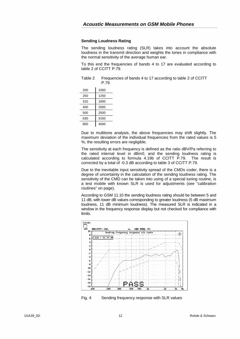
According to GSM 11.10 the sending loudness rating should be between 5 and11 dB, with lower dB values corresponding to greater loudness (5 dB maximumloudness, 11 dB minimum loudness). The measured SLR is indicated in awindow in the frequency response display but not checked for compliance withlimits.
Fig. 4 Sending frequency response with SLR values

Acoustic Measurements on GSM Mobile Phones
1GA39_0D 13 Rohde & Schwarz
Receiving Frequency Response and Loudness Rating
Receiving Frequency Response
The input frequency response is specified as the transmission ratio in dB ofthe sound pressure in the artificial ear to the input voltage at the voice coderinput of CMD.
The mobile under test is installed in the LRGP position (CCITT P.76) andthe speaker is sealed to the artificial ear.
The voice coder is driven so that tones with an internal reference level of -16 dBm0 are obtained. The noise pressure in the artificial ear is measuredand evaluated.
The receiving frequency response must be within the limit lines specified intable 30.2 of GSM 11.10. The absolute sensitivity is not yet taken intoaccount.
Table 3 Limit lines according to GSM 11.10 table 30.2
Frequency (Hz) Upper Limit (dB) Lower Limit (dB)
100 -12
200 0
300 2 -7
500 * -5
1000 0 -5
3000 2 -5
3400 2 -10
4000 2
* Intermediate values are obtained when a straight line is drawn between the specifiedvalues and a logarithmic frequency scale and a linear dB scale are used.
The offset of the measured frequency response to the upper or lower limitcurve is calculated and then the total curve is shifted by the mean value ofthe maximum and minimum offset. Then another limit check is performed.If the shifted curve is within the limit lines, PASS is output, otherwise FAIL isoutput. The limit check is performed at each measured frequency. If themeasured value and the end point of a limit curve are not at the samefrequency, it may happen that the trace slightly crosses a corner of the limittrace although there are no limit violations.
Receiving Loudness Rating
The receiving loudness rating (SLR) takes into account the absoluteloudness in the receive direction and weights the tones in compliance withthe normal sensitivity of the average human ear.
To this end the frequencies (Hz) of bands 4 to 17 are evaluated accordingto table 2 of CCITT P.79.

Acoustic Measurements on GSM Mobile Phones
1GA39_0D 14 Rohde & Schwarz
Table 4 Frequencies (Hz) of bands 4 to 17 according to table 2 of CCITTP.79
200 1000
250 1250
315 1600
400 2000
500 2500
630 3150
800 4000
Due to multitone analysis, the above frequencies may shift slightly. Themaximum deviation of the individual frequencies from the rated values is 5%, the resulting errors are negligible.
The sensitivity at each frequency is specified as a ratio in dBPA/V referringto the rated internal signal level, and the receiving loudness rating iscalculated according to formula 4.19c of CCITT P.79 with correction of theear sensitivity according to table 4 of CCITT P.79.
Due to the inevitable input sensitivity spread of the CMD’s voice coder,there is degree of uncertainty in the calculation of the sending loudnessrating. The sensitivity of the CMD can be taken into account using a specialtuning routine if a test mobile with known RLR is used for adjustments (see“calibration routines” on page).
The receiving loudness rating depends on the volume set on the test mobileand, according to GSM 10.11, should be between -1 V and +5 V at a ratedvolume setting, with lower dB values corresponding to a higher volume.
The RLR should not fall below -13 dB when maximum volume is set on thephone (i.e. the maximum receiving loudness should not exceed a certainvalue to avoid damage to the human ear). The measured SLR is indicatedin a window in the frequency response display but not checked forcompliance with limits.
Sidetone Masking Rating STMR
The so-called sidetone path is the desired output from the part of the signalpicked up by the microphone from the phone's speaker. This should createa natural hearing impression for the person speaking on the phone as isencountered under normal call conditions, i.e. via the acoustic pathbetween his mouth and ear.
The mobile under test is installed in the LRGP position (CCITT P.76) andthe speaker is sealed to the artificial ear.
The artificial mouth generates tones with a sound pressure of -4.7 dBPa atthe MRP (mouth reference point) and the sound pressure is measured inthe artificial ear.
The suppression of the sidetone path is determined at each frequencyaccording to table 2, CCITT P.79, and the side tone masking rating STMRcalculated according to formula 8.4 of CCITT P.79 with the weightingfactors of tables 6 and 4 of CCITT P.79 taken into account.
When the phone is set to the rated volume, the STMR should be within 8and 18 dB.

Acoustic Measurements on GSM Mobile Phones
1GA39_0D 15 Rohde & Schwarz
Fig. 5 Display of numeric values on the screen, e.g. for sidetonemasking rating
Listener Sidetone Rating LSTR
The listener sidetone rating defines the effect of interference sound on thevoice quality. The telephone microphone not only picks up the caller’s voicebut also any noise in the environment. The listener sidetone rating is theratio of the wanted to the unwanted sound. For measuring the LSTR, astandard sound field is required, which is created with the aid of eight noisegenerators producing pink noise with a sound pressure of 70 dB(A).Provided the eight sources are adequately arranged in the test chamber, ahomogeneous sound field is obtained in the center. Refer to GSM 11.10,section 30.5.2.4.2, for information on setup and levels.
Since a standard sound field is required for the LSTR measurement, themeasurement is far more involved than most of the other acousticmeasurements, but the complexity is necessary to test for the effects ofinterfering sound on the transmission quality. An automatic evaluation isincluded in the test program.
The sound field has to be created by means of external generators. Thetest program determines the listener sidetone rating on the assumption thatthe sound field is in compliance with the standard.
The mobile under test is installed in the LRGP position (CCITT P.76) andthe speaker sealed to the artificial ear.
The setup is installed in a chamber with a standard sound field. The energydistribution in this field is defined by GSM 11.10 and therefore known.
The energy of the sound pressure in the artificial ear is measured by meansof third-octave analysis in the 14 bands with center frequencies from 200 to4000 Hz, and the suppression of the listener sidetone path is determined foreach band from the known rated values of the sound field. The listenersidetone rating LSTR is then calculated with formula 8.4 of CCITT P.79 bytaking into account the weighting factors of tables 6 and 4 of CCITT P.79.
The LSTR should not be less than 15 dB.

Acoustic Measurements on GSM Mobile Phones
1GA39_0D 16 Rohde & Schwarz
Echo Loss
The echo loss is the attenuation between the voice coder input and thevoice decoder output (gain of voice coder + decoder = 1). Normally theecho loss is caused by internal acoustic coupling between the telephonereceiver and the microphone. Since the echo considerably reduces thesound transmission quality, it should not exceed a certain value.
To obtain realistic results, an artificial voice is used for the echo loss test.The currently applicable GSM 11.10 standard does not take into accountthat the RMS value (referred to the peak level) of the stochastic signal ofthe artificial voice is considerably lower than that of previously used testsignals with sinusoidal tones (crest factor of voice signals approx. 20 dBcompared with 3 dB of sinewave signal). As a result the system can only bedriven at low level and the demanded echo loss value of 46 dB correspondsto about the theoretical quantization noise of the GSM system. For thisreason a PASS verdict will normally not be issued from this test. Althoughthese measurements are of great importance from an acoustic point ofview, the echo loss measurement in the type approval test of GSM mobilesis currently suspended until a new definition is available.
The numeric values obtained in the echo loss measurement maynevertheless be used for a quality assessment of the telephone.
The mobile under test is installed in the LRGP position (CCITT P.76) andthe speaker is sealed to the artificial ear.
The artificial voice defined by CCITT P.50 is generated as a test signal andapplied to the voice coder. The voice is sent for 10 seconds. During thisperiod the spectral energy distribution of this signal is measured in the third-octave bands from 200 Hz to 4 kHz. The same part of the voice is sentagain for 10 seconds and the spectral distribution in the output signal of thevoice decoder is measured. The echo loss is then calculated from thedifferences of the bands according to CCITT G.122. This measurement isperformed for a male and a female voice and the final result is the meanvalue of the two measurements.
The real gain of the voice coder and decoder must also be considered inthe result. The gain of the coder path is be determined using of an auxiliaryroutine (see “calibration routines” on page).
GSM 11.10 specifies an echo loss of at least 46 dB. Normally this cannotbe achieved for the above reasons, but values of up to approximately 40 dBcan be expected. Since the microphone also picks up any side noise andtreats it like an echo, it is essential that the test chamber is shielded againstexternal noise.

Acoustic Measurements on GSM Mobile Phones
1GA39_0D 17 Rohde & Schwarz
Stability Margin
The stability margin is measured to test the susceptibility of the phone toacoustic feedback and instability.
For the test, the telephone is placed on an even, hard board with thereceiver and microphone pointing downwards.
A loop is closed in the UPL between the receive and the voice channeland an overall gain of 6 dB set. The gain of the coder is automatically takeninto account (see also echo loss).
To activate the loop, a noise signal of -10 dBm0 in line with CCITT O.131 isapplied for 1 seconds and then switched off with the loop remaining closed.
Listening for whether resonances or oscillations are produced. If there areno oscillations, the minimum requirements to GSM 11.10 for a stabilitymargin of 6 dB are complied with.
Sending Distortion
The S/N ratio in the transmit path is measured as a function of the soundlevel. As specified by GSM 11.10, the voice coder is excluded from themeasurement, but when a standard GSM mobile is used, this measurementcan only be performed with the voice coder and decoder included. For thisreason the limit values to GSM 11.10 may be taken as a reference but theyneed not necessarily be adhered to.
A sinusoidal tone of 1015 Hz is used for the measurement. At thisfrequency, coding yields a sufficiently stable output signal.
The mobile under test is installed in the LRGP position (CCITT P.76) andthe speaker is sealed to the artificial ear.
The test signal is generated with the artificial mouth at the MRP (mouthreference point) and the SINAD value of the received signal is measured atthe CMD’s decoder output.
The acoustic reference level ARL is defined as the sound pressure whichcreates a signal level of -10 dBm0 in the transmit channel. An automaticroutine varies the sound pressure at the artificial mouth until the desiredlevel is attained. This value is then used as a reference for determining theSINAD value versus level.
The SINAD value is measured at sound pressures between -35 dB and +10dB relative to the acoustic reference level ARL and compared with the limitlines specified in table 30.3 of GSM 11.10.
Table 5 Limit lines specified in table 30.3 of GSM 11.10
dB relative to ARL Level ratio
-35 dB 17.5 dB
-30 dB 22.5 dB
-20 dB 30.7 dB
-10 dB 33.3 dB
0 dB 33.7 dB
7 dB 31.7 dB
10 dB 25.5 dB

Acoustic Measurements on GSM Mobile Phones
1GA39_0D 18 Rohde & Schwarz
The measurement is performed up to a maximum sound pressure of 10dBPa at the artificial mouth so the actual trace may end at an lowerpressure
If the measured trace is above the limit line, a PASS is output otherwise aFAIL is displayed. Since this measurement includes voice coding in contrastto type approval tests, a PASS verdict cannot always be expected. In thiscase the offset of the trace to the limit line has to be visually checked.
Receiving Distortion
The S/N ratio in the receive path is measured as a function of the acousticsignal level. As specified by GSM 11.10 the voice coder is excluded fromthe measurement, but when a standard GSM mobile is used, themeasurement can only be performed with the voice coder and decoderincluded. For this reason the limit values to GSM 11.10 can be taken as areference but they need not necessarily be adhered to.
A sinusoidal tone of 1015 Hz is used for the measurement. At thisfrequency, coding yields a sufficiently stable output signal.
The mobile under test is installed in the LRGP position (CCITT P.76) andthe speaker is sealed to the artificial ear.
The test signal is applied to the input of the CMD voice coder and theSINAD of the sound pressure in the artificial ear is measured withpsophometric weighting to CCITT G.714.
The SINAD of the sound pressure is measured at levels between -45 dBm0and 0 dBm0 and compared with the limit lines given in table 30.4 of GSM11.10.
Table 6 Limit lines given in table 30.4 of GSM 11.10
Level Level ratio
-45 dBm0 17.5 dB
-40 dBm0 22.5 dB
-30 dBm0 30.5 dB
-20 dBm0 33.0 dB
-10 dBm0 33.5 dB
-3 dBm0 31.2 dB
0 dBm0 25.5 dB
The measurement is performed up to a maximum sound pressure of 10dBPa in the artificial ear, so that the actual trace may end at a lowerpressure.
If the measured trace is above the limit line, a PASS is issued otherwise a FAIL.Since this measurement includes voice coding in contrast to the type approvaltest, a PASS verdict cannot always be expected. In this case the offset of thetrace to the limit line has to be visually checked.

Acoustic Measurements on GSM Mobile Phones
1GA39_0D 19 Rohde & Schwarz
Fig. 6 Typical result of receiving distortion measurement
Idle channel noise sending
The noise voltage at the voice decoder output is measured with thetelephone set up in a quiet environment (< 30 dB(A)).
The mobile under test is installed in the LRGP position (CCITT P.76) andthe speaker is sealed to the artificial ear.
The decoder output voltage is measured, psophometrically weightedaccording to CCITT G.223 and calculated at the internal level in dBm0p.
The idle noise level should not exceed -64 dBm0p.
Idle channel noise receiving
The sound pressure in the artificial ear is measured with the phone set up ina quiet environment (<30 dB(A)).
The mobile under test is installed in the LRGP position (CCITT P.76) andthe speaker is sealed to the artificial ear.
The sound pressure in the artificial ear is measured with A-weighting on.
With optimum volume set on the mobile, the sound pressure should notexceed -57 dBPa(A).
At maximum volume, the sound pressure should not exceed -54 dBPa(A).
This measurement makes high demands on the sound insulation of the testchamber and the S/N ratio of the measuring microphone includingpreamplifier in the artificial ear. A comparison measurement with the testmobile switched off or without a DUT shows the measurement reserves ofthe test equipment. Due to the inherent noise of the Audio Analyzer UPL,measurements can be made to about -80 dBPa(A) at 0 dB microphonegain, and even to lower values when a higher microphone gain is set.
Thus the compliance with the interfering noise level of below 30 dB(A) asspecified by GSM 11.10 for the test chamber can be checked. 30 dB(A)corresponds to -64 dBPa(A) (1 Pa corresponds to a sound pressure level of94 dB).

Acoustic Measurements on GSM Mobile Phones
1GA39_0D 20 Rohde & Schwarz
5 Calibration Routines
Microphone Calibration
Before a mobiles can be rested, the absolute sensitivity of the microphonein the artificial ear is determined using a sound level calibrator such as 4231from Brüel & Kjaer with a sound pressure level of 94 dBSPL or a soundpressure of 1 Pa at 1 kHz.
1. After switching off the microphone power supply.
Note: The 200 V polarization voltage of the microphone may causea slight electric shock. The current is harmless but themicrophone amplifier may be damaged
2. Remove the microphone from the artificial ear.
3. Screw back the microphone capsule and switch on the operating voltage.
4. Insert the microphone fully into the adapter of the sound level calibrator andswitch on the calibrator.
Note: After inserting the microphone wait about 10 s to allow forstatic pressure compensation.
1. Select the CALIBRATION level with function key F12.
--- CALIBRATION ---
F5 F6 F7 F8 F9 F10 F11 F12
<- CAL_MIC CAL_MOU CODEC ADJ_SLR ADJ_RLR
2. Call the test routine with function key F6 CAL_MIC.
The output voltage of the microphone is measured and the sensitivitydisplayed with reference to 1 Pa. With 0 dB preamplification of themicrophone, the displayed sensitivity should be about the value in thecalibration certificate of the microphone capsule (typical value formicrophone capsule 4134 and artificial ear 4185 is approx. 12 mV/Pa). Ifthe measured voltage is below 3 mV, an error message is displayed.Possible error sources may be a switched off microphone power supply or adisabled calibrator. In this case the program requests the test to berepeated. After switching on the microphone power supply wait for 20seconds before restarting the measurement with RUN.
The measured reference value is stored in a nonvolatile memory and usedfor all subsequent measurements with the artificial ear.

Acoustic Measurements on GSM Mobile Phones
1GA39_0D 21 Rohde & Schwarz
Artificial Mouth Calibration
Before a mobiles can be rested, the absolute sensitivity and frequencyresponse of the artificial mouth have to be measured and corrected with theaid of the removed and previously calibrated measuring microphone of theartificial ear. The measuring microphone is used as a reference fordetermining the frequency response of the mouth. The frequency responseof the microphone can be ignored in the test frequency range (100 Hz to 8kHz) (see also calibration certificate of microphone capsule).
Since interfering sound falsifies the corrections, the artificial mouth shouldbe calibrated in a sound-proof test chamber.
Fit the microphone at right angles to the mouth at the reference point MRPusing the gauge supplied with the mouth (positioning at right angles isnecessary because microphone capsule 4134 from ear 4185 is pressure-calibrated).
À Press F12 to display the calibration keys:
--- CALIBRATION ---
F5 F6 F7 F8 F9 F10 F11 F12
<- CAL_MIC CAL_MOU CODEC ADJ_SLR ADJ_RLR
À Call the test routine by pressing function key F7 CAL_MOU.
First the sound pressure generated at the MRP is set to exactly -4.7dBPa in an automatic measurement routine at 1 kHz. The requiredgenerator voltage is stored in a nonvolatile memory and used as areference for all subsequent settings with the artificial mouth. If thesound pressure cannot be adjusted to -4.7 dBPa, an error message isdisplayed with a request to check the connection of the artificial mouthand to repeat the measurement. A possible error source could be thatthe supplied transformer is not connected between the generator andthe artificial mouth.
The uncorrected frequency response of the artificial mouth is nowmeasured and displayed. Next, the frequency response is measuredwith the inverse frequency response correction automatically selected inthe generator (equalization). Residual errors caused by non-linearities ofthe speaker in the mouth are measured and considered as finecorrection in the final equalization file.
To verify the results, the absolute sound pressure versus frequency ismeasured at a sound pressure of 4.7 dBPa (reference value for most ofthe measurements). The absolute sound pressure at each frequencymust be within a tolerance band of -4.7 dBPa ±0.2 dB. Correctcalibration without interfering sound yields an almost straight line in themiddle between the two limit lines.

Acoustic Measurements on GSM Mobile Phones
1GA39_0D 22 Rohde & Schwarz
Calibration of Voice Coder Loop
For measuring the echo loss or stability margin, the test signal is routed viathe voice coder to the test mobile and back again via the voice decoder. Toobtain correct measurement results the total gain of this loop must beknown. This loop cannot be closed in the CMD.
A mobile has to be connected to the CMD’s RF interface to measure theloop gain. Using a standard Layer 3 command, the mobile can be set sothat the audio data sent via the RF interface is returned unchanged, i.e. atotal echo is obtained for the audio data. The overall loop gain is then themeasured echo loss. The measured gain is saved and used for correctionsin subsequent echo loss measurements. The typical gain of the CMD loopis approx. 19 dB.
À Press F12 to display the calibration keys:
--- CALIBRATION ---
F5 F6 F7 F8 F9 F10 F11 F12
<- CAL_MIC CAL_MOU CODEC ADJ_SLR ADJ_RLR
À Call the test routine with the F8 CODEC function key
À Select the CODEC CAL speech mode when requested to do so.This selection is only possible if the LOOP COMMAND is activated withENABLE. Select LOOP COMMAND on the CMD by pressing NETWORKand then NEXT PAGE and then ENABLE.
An echo loss measurement is now performed with the aid of the artificialvoice but, in contrast to a normal echo loss measurement, theconnected mobile is set to total echo. This echo is measured accordingto CCITT P.50 for a male and a female voice. The mean value of thetwo voices gives the final result which should be approx. 19 dB.
Adjustment Routine for Sending Loudness Rating (SLR)Using a Reference Mobile
The sensitivity of the CMD voice decoder must be considered whenmeasuring the sending loudness rating. With the previously describedcalibration of the voice coder loop, only the sum gain but not the separategains of coder and decoder can be measured.
For this reason the nominal gain of the voice decoder is used for calculatingthe SLR, but the nominal gain may differ by up to approx. 2 dB. Theaccuracy of the SLR calculation can be considerably increased when a testmobile with a known SLR is used for calibration, e.g. a mobile from a typeapproval mobile with measurement via the DAI interface.
The adjustment routine asks for the rated SLR of the connected mobile,performs three SLR measurements and then averages the results. A correctionvalue is calculated from the difference between the nominal SLR and themeasured SLR, stored and used for all subsequent SLR measurements. Thisadjustment takes into account the characteristics of the CMD and need only berepeated when the CMD is replaced.

Acoustic Measurements on GSM Mobile Phones
1GA39_0D 23 Rohde & Schwarz
À The mobile under test is installed in the LRGP position (CCITT P.76) and thespeaker is sealed to the artificial ear.
À Set up a CALL to the CMD and select the HANDSET mode, if necessary.
À Press F12 display the calibration keys:
--- CALIBRATION ---
F5 F6 F7 F8 F9 F10 F11 F12
<- CAL_MIC CAL_MOU CODEC ADJ_SLR ADJ_RLR
À Call the test routine by pressing function key F9 ADJ_SLR.
À Enter the known SLR value and confirm with RETURN.
The program performs the measurement and saves the correction value ina nonvolatile memory.
Adjustment Routine for Receiving Loudness Rating (CLR)Using a Reference Mobile
The sensitivity of the CMD’s voice coder must be considered whenmeasuring the receiving loudness rating. With the previously describedcalibration of the voice coder loop, the sum gain but not the separate gainsof coder and decoder can be measured.
For this reason the nominal gain of the voice decoder is used for calculatingthe RLR, but the nominal gain may differ by up to approx. 2 dB. Theaccuracy of the RLR calculation can be considerably increased when a testmobile with known RLR is used for calibration, e.g. a mobile from a typeapproval measurement via the DAI interface.
The adjustment routine asks for the rated RLR of the connected mobile,performs three RLR measurements and then averages the results. A correctionvalue is calculated from the difference between the nominal RLR and themeasured RLR, saved and used for all subsequent RLR measurements. Thisadjustment takes into account the characteristics of the CMD and need only berepeated when the CMD is replaced.
À The mobile under test with known SLR is installed in the LRGP position(CCITT P.76) and the speaker sealed to the artificial ear.
À Set up a CALL to the CMD and select the HANDSET mode, if necessary.
À Press to the display F12 calibration keys:.
--- CALIBRATION ---
F5 F6 F7 F8 F9 F10 F11 F12
<- CAL_MIC CAL_MOU CODEC ADJ_SLR ADJ_RLR

Acoustic Measurements on GSM Mobile Phones
1GA39_0D 24 Rohde & Schwarz
À Call the test routine by pressing function key F10 ADJ_RLR.
À Enter the known RLR value and confirm with RETURN.The program performs the measurement and saves the correction value innonvolatile memory.
6 Processing of Measurement Results
Printing, Storing and Displaying of Measurement Results
The result of each measurement is graphically or numerically displayed onthe screen and, if applicable, a PASS or FAIL verdict is output.
The following softkeys are displayed.
F5 F6 F7 F8 F9 F10 F11 F12
CONT TRC_FILE PCX_FILE HARDCOPY
Pressing the CONT key brings back the selection menu for themeasurement.
When the TRC_FILE key is pressed, the displayed trace is saved in ASCIIformat in a file. This file has the name TRCxx.TRC, with xx representing aconsecutive number (of max. 5 digits). This allows processing ofmeasurement results with other programs. The TRC_FILE key has tofunction when the results are numerically displayed.
The screen content can be copied into a PCX file using the PCX_FILE key.This file has the fixed name PICxx.PCX, with xx representing a consecutivenumber (of max. 5 digits). Thus the measurement results can also be usedin word processing programs, for instance. To allow also numeric values tobe stored in a PCX file, the whole screen content without the softkey line iscopied.
Since both the TRC and the PCX files are consecutively numbered, it isuseful to copy the files of a measurement sequence, for instance, and tosave them under a new name. In this case the original TRCxx.TRC andPICxx.PCX files can be cleared. Thus results can be identified more easilyand a mix up between them avoided. (The files can be copied and renamedusing common DOS commands.)
Call end a DOS shell called after terminating of the test program (e.g. withkey F5) by entering the command SHELL <RETURN>. Entering EXIT<RETURN> brings back BASIC without the program being cleared. Theprogram can be restarted immediately by entering RUN.
The screen content can be output to a printer by pressing the HARDCOPYkey.
Printer type and desired settings are not selected by the program but theprinter selected last and set in UPL manual mode will be chosen. For thisreason the desired printer, scaling and format should be manually set oncein the OPTION panel of UPL prior to the measurement. It is recommendedto select a LOW or MEDIUM resolution and as far as possible integer scalefactors for the printer output. If fractional scale factors (especially values <

Acoustic Measurements on GSM Mobile Phones
1GA39_0D 25 Rohde & Schwarz
1) are used, the pixels values are interpolated and the print quality could bereduced.
It may be useful to first print a test copy to check the print quality. Contraryto manual operation, no COMMENT line is printed in this case and theprogram automatically sends a FORM FEED after each print to throw outthe hardcopy.
Numerical values are automatically added to a result file after eachmeasurement. This file has the name RES_GSM.LOG.
Each result is written in a separate line with the measurement in plain text,showing the value, date and time. Thus all numeric measurement resultscan be called again after a test sequence has been performed andevaluated.
As with TRC and PCX files, it may be useful to copy the RES_GSM.LOGfile after a measurement sequence and to save it under a new name. Afterthis the RES_GSM.LOG file can be cleared. Thus results can be identifiedmore easily and a mix up between them avoided. To this end a DOS shellcan be called after termination of the test program (e.g. with key F5) byentering the command SHELL <RETURN>. The files can be copied andsaved under another name using common DOS commands.
Entering EXIT <RETURN> brings back BASIC without the program beingcleared. The program can be immediately restarted with RUN.

Acoustic Measurements on GSM Mobile Phones
1GA39_0D 26 Rohde & Schwarz
7 Terminating the Application
As long as the arrow → is displayed below the F12 key, another set ofsoftkeys can be called with this key. With F5 the user can return to theprevious set of softkeys, so long as the arrow ← is displayed below the key.If F5 displays END, there is no previous set.
F5 F6 F7 F8 F9 F10 F11 F12
END SEND RECEIVE STMR LSTR ECHO STAB-MRG ->
After selecting END by pressing the F5 key, the following query isdisplayed:
À "Do you want to terminate the program <Y><N>?“
Upon confirmation with Y, the program is aborted but not cleared. Thesoftkey line for BASIC is then restored.
The software can be terminated any time under BASIC with the keycombination CTRL BREAK. The program can be continued with CONTand restarted with RUN.
8 Ordering information
Audio AnalyzerUPL DC to 110 kHz 1078.2008.06
Option required for UPLUPL-B6 Extended Analysis 1078.4500.02UPL-B8 Mobile Phone Test Set 1117.3505.02UPL-B10 Universal Sequence Controller 1078.3904.02
Radiocommunicattion TesterCMD52 GSM 900 /GSM 1800 1050.9008.52CMD53 GSM 900 /GSM 1800 1050.9008.53CMD55 GSM 900 /GSM 1800 1050.9008.55
Option required for CMDCMD-B5 Real Time Speech
Coder/Decoder for GSM1051.8657.02
ROHDE & SCHWARZ GmbH & Co. KG . Mühldorfstraße 15 . D-81671 MünchenPostfach 80 14 69 . D-81614 München . Tel (089) 4129 -0 · Fax (089) 4129 - 3777 . Internet: http://www.rsd.de


![[Jeffie Betz] Playing Piano](https://img.dokumen.tips/doc/110x75/577cd07b1a28ab9e78925f4b/jeffie-betz-playing-piano.jpg)