Embed Size (px)
Citation preview

Acoustic holography
LMS Test.Lab
Rev 12A
Copyright LMS International 2012


Rev 12A 3
Table of Contents
Chapter 1 Introduction ................................................................................................... 5
Chapter 2 Acoustic holography concepts .................................................................... 7
Section 2.1 Temporal and spatial frequency ........................................................... 7 Section 2.2 Time domain ........................................................................................ 8 Section 2.3 Spatial domain ..................................................................................... 8 Section 2.4 (Back) propagating to other planes .................................................... 12 Section 2.5 The Wiener filter and the AdHoc window ......................................... 13 Section 2.6 Derivation of other acoustic quantities .............................................. 14


Chapter 1 Introduction
Rev 12A 5
Chapter 1 Introduction
Acoustic holography allows you to accurately localize noise sources. It
therefore helps in both the reduction of unwanted vibro-acoustic noise and
optimization of noise levels.
It :
estimates the acoustic power and the spectral content emitted by the object
under examination.
maps sound pressure, velocity and intensity on the measurement plane and
on all parallel planes. The mapping of these acoustical quantities outside
the measurement plane is done through acoustical holography (near field -
far field).
estimates the acoustic level of the principal sources, including contribution
analysis.
This document describes the principles of taking acoustic measurements and the
subsequent analysis of acoustic holography data, for both stationary and
transient measurements.
Basic principles
In performing acoustic holography, you need to measure cross spectra between
a set of reference transducers and the hologram microphones. From these
measurements you can derive sound intensity, particle velocity and sound
power values.
A basic assumption is that you are operating in free field conditions and that the
energy flow is coming directly from the source. Measurements need to be taken
close to the source.
It provides you with an accurate 3D characterization of the sound field and the
source with a higher spatial resolution than is possible with conventional
intensity measurements.


Chapter 2 Acoustic holography concepts
Rev 12A 7
Chapter 2 Acoustic holography concepts
In This Chapter
Temporal and spatial frequency ......................................... 7
Time domain....................................................................... 8
Spatial domain .................................................................... 8
(Back) propagating to other planes..................................... 12
The Wiener filter and the AdHoc window ......................... 13
Derivation of other acoustic quantities ............................... 14
The principle of acoustic holography is to decompose the measured pressure
field in plane waves, by using a spatial Fourier transform. With the frequency
being fixed, we can calculate how each of these plane waves propagates, and by
adding them we can find the pressure field on any plane which is parallel to the
measurement plane.
Consider an acoustic wave. Measuring the pressure on a plane means cutting the
wavefronts by the measurement plane:
The goal is to determine the whole acoustic wavefront from the known pressure
on the measurement plane. Each microphone in the array measures the
complex pressure (amplitude and phase).
Section 2.1 Temporal and spatial frequency
In considering how to do this we will compare the time and the spatial domain.

Chapter 2 Acoustic holography concepts
8 LMS Test.Lab Acoustic holography
Section 2.2 Time domain
When considering measurements in the time domain, then the position from the
sound source (m) is fixed and we obtain a measure of the pressure variation as a
function of time.
The transformation from the time to the frequency domain is achieved using the
Fourier Transform given below
Section 2.3 Spatial domain
If we now consider measurements where time is fixed and pressure varies as a
function of distance, we can obtain a measure of energy flow.
The spatial frequency of this function or wavenumber (k0) is defined as :
If we fix the temporal frequency, this means that the acoustic wavelength is
fixed too.

Chapter 2 Acoustic holography concepts
Rev 12A 9
The complex pressure as a function of the space is called the pressure image at
the specified frequency.
Conversion from the spatial domain is also done using a Fourier transform. In
Acoustic holography pressure is measured in two dimensions (x and y for
example), so a 2-dimensional transformation is performed.
where S (kx , ky) is the spatial transform of the measured pressure field to the
wavenumber (kx and ky)
domain resulting in the 2-D hologram pressure field.
A measured pressure (sound) wave with a particular temporal frequency can
propagate in a number of directions, so the wavenumber vector (k) will have a
number of components. The appearance of these vectors depends on the plane
on which you are looking at them. The aim is to find the components of these
vectors in the 2 dimensions that define the plane and to do this projections of
the vectors in the plane are made.
Summation of plane waves

Chapter 2 Acoustic holography concepts
10 LMS Test.Lab Acoustic holography
The spatial Fourier transform implies that a measured pressure field can be
considered as a sum of sinusoidal functions.
Each of these sinusoidal functions can be understood as the result of cutting the
wavefronts of a plane wave by the measurement plane.
There is a coincidence between the nodes of the sinusoidal function and the
wavefronts. In effect, decomposing the pressure field into a sum of sinusoidal
functions means decomposing the real acoustic wave into a sum of plane waves.
Whatever the angle of incidence, the spatial periodicity must be greater than the
wavelength (l). Propagating and evanescent waves
There are two kinds of plane waves :
propagating waves - whose level remains the same as they propagate but
who undergo a phase shift.
evanescent waves - whose level decreases as they propagate.
Propagating waves represent the sound field that is propagated away from the
near towards the far field. Evanescent waves describe the complex sound field

Chapter 2 Acoustic holography concepts
Rev 12A 11
in the near field of the source.
To understand why we must take evanescent plane waves into account, let us
consider our decomposition of the pressure field into sinusoidal functions. If the
spatial periodicity of a sinusoidal function is shorter than the wavelength, it
cannot be the result of cutting a propagating plane wave by the measurement
plane :
Whatever the direction of the propagating plane wave may be, there is no
possible coincidence between the nodes of the sinusoidal function and the
wavefronts. Therefore, this sinusoidal function must be understood as the
intersection between an evanescent wave (which can have a smaller spatial
periodicity than propagating waves) and the measurement plane.
A mathematical interpretation of the evanescent waves is based on the value of
kz which is the component perpendicular to the measurement directions in the
wave number domain.
kz can be determined from the wave number k0 and the known values of kx and
ky from the transformation.
Chapter 2 Acoustic holography concepts
12 LMS Test.Lab Acoustic holography
kz is real when (the spatial periodicity is greater than
the wavelength). This means that the waves lie in the circle defined by the
radius w/c in the wave number domain. kz is imaginary outside of this region.
When kz is imaginary, the propagation factor becomes a damped exponential
function (e-jkz z) meaning that a propagated wave undergoes an amplitude
modification while the phase is not changed.
Section 2.4 (Back) propagating to other planes
Pressure levels at other planes can be found using Raleigh's integral Equation
with Dirichlet's Green function :
where the Green function Gd can be thought of as the transformation function to
transform the sound pressure field from one plane to another. We can use wave
domain properties (k) to predict the pressure at a different spatial position (z).
The practical computation of Raleigh's equation is:
where z' is the measurement plane and z is the position of the required plane.
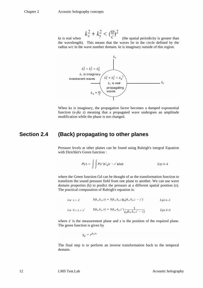
The green function is given by
The final step is to perform an inverse transformation back to the temporal
domain.

Chapter 2 Acoustic holography concepts
Rev 12A 13
Section 2.5 The Wiener filter and the AdHoc window
As mentioned above, evanescent waves undergo a change in amplitude when
propagating. Propagating towards the source implies an amplification of the
signal that is a function of kz. Evanescent waves that lie far away from the unit
circle have a large kz, therefore their amplitude is amplified significantly when
propagating to the source. The contribution of these evanescent waves results
in an increase of spatial resolution. Note that the inclusion of evanescent waves
is only appropriate when propagating towards the source.
Propagating away from the source, the evanescent waves decrease so rapidly in
amplitude that their contribution to the spatial resolution becomes negligible.
However the further away a wave is located from the circle, the less accurate
the amplitude estimate becomes so that at a certain point noise is propagated
and at that point the propagated image starts to blur.
When propagating towards the source, a Wiener filter can be used to include a
certain number of evanescent waves to improve the resolution. Taking a higher
number of waves taken into account may result in the amplification becoming
unstable. This depends on a parameter of the Wiener filter known as the Signal
to Noise Ratio (SNR). When the SNR value is greater than 15dB, then the
amplification will become unstable as the number of evanescent waves included
increases. Using an low SNR value (5dB for example) means that the
evanescent waves are taken into account but they are so attenuated that the
improvement in resolution is negligible. The default value of 15dB provides the
best compromise in terms of resolution and amplification.
When the Wiener filter is used, the pressure image needs to be multiplied by a
two-dimensional window. As is the case with a single FFT, the observed
pressure must be 'periodic' within the observed hologram. If this is not the case,
then truncation errors occur as with a single FFT. These truncation errors
manifest themselves as ghost sources at the borders of the observed area.
Two windows are used:
The rectangular window,
which does not modify the pressure image. In case of a rectangular window,
only propagating waves are included in the calculations resulting in a resolution
equivalent to an intensity measurement.
The so-called Ad Hoc window
For a time signal, the FFT algorithm takes the time signal and duplicates it from
minus to plus infinity. If the amplitude of the measured time signal differs

Chapter 2 Acoustic holography concepts
14 LMS Test.Lab Acoustic holography
between the start and the end of the window, a discontinuity occurs during this
multiplication introducing an error in the FFT algorithm. This can be corrected
using a Hanning window. Holography used a double FFT so the AdHoc
window is used, which is basically a two dimensional Hanning window thus
removing discontinuities in the both the x and y directions.
The one-dimension Ad Hoc window (W) would be:
Section 2.6 Derivation of other acoustic quantities
If we know how the plane waves propagate, we can calculate the pressure field
in any parallel plane, by adding the contributions of all plane waves. This will
be correct only if all acoustic sources are on the same side of both planes :
Knowing the pressure field on the parallel plane, it is possible to calculate the
particle velocity and eventually the intensity on this plane.
The particle velocity (V) will be known if the pressure differential can be
determined -which is the case with Acoustic holography since the pressure can
be measured at r and (r + dr)

Chapter 2 Acoustic holography concepts
Rev 12A 15
Once the pressure and the velocity are known then the intensity is just the
product of the two.

Rev 12A 17
Index
(
(Back) propagating to other planes • 13
A
Acoustic holography concepts • 7
D
Derivation of other acoustic quantities • 15
I
Introduction • 5
S
Spatial domain • 8
T
Temporal and spatial frequency • 7
The Wiener filter and the AdHoc window • 14
Time domain • 7