Embed Size (px)
Citation preview
AcomSoftware Configuration
System Versions4.0.28, 4.0.28.1, and 4.0.29
025-9529P
©Zetron, Inc. All rights reserved. This publication is protected by copyright; information in this document is subject to change without notice. Zetron and the Zetron logo are registered trademarks of Zetron, Inc. Other company names and product names may be the trademarks or registered trademarks of their respective owners. This publication may not be reproduced, translated, or altered, in whole or in part, without prior written consent from Zetron, Inc.
Software License
The Zetron software described in this manual is subject to the terms and conditions of Zetron's Software License Agreement, a copy of which is contained on the product distribution media or otherwise provided or presented to buyer. Installation and/or use of the Zetron software constitutes acceptance of Zetron's Software License Agreement.
Limited Warranty
Buyer assumes responsibility for the selection of the Products to achieve buyer's or its customer's intended results obtained from the Products. If buyer has provided Zetron with any requirements, specifications or drawings, or if Zetron provides buyer with such materials, such materials are provided solely for buyer's convenience and shall not be binding on Zetron unless agreed in writing by the President of Zetron. ZETRON DOES NOT WARRANT THAT THE PRODUCTS OR ITS CUSTOMER'S REQUIREMENTS OR SPECIFICATIONS OR THAT OPERATION OF THE PRODUCTS WILL BE UNINTERRUPTED OR ERROR FREE. SUBJECT TO THE LIMITATIONS SET FORTH BELOW, Zetron warrants that all Zetron Products and Zetron Accessories will be free from material defects in material and workmanship for one year from date of shipment (except where indicated otherwise in the Zetron Price Book). For buyer's convenience, Zetron may purchase and supply additional items manufactured by others. In these cases, although Zetron's warranty does not apply, buyer shall be the beneficiary of any applicable third party manufacturer's warranties, subject to the limitations therein. Zetron's warranty covers parts and Zetron factory labor. Buyer must provide written notice to Zetron within the warranty period of any defect. If the defect is not the result of improper or excessive use, or improper service, maintenance or installation, and if the Zetron Products or Zetron Accessories have not been otherwise damaged or modified after shipment, AS ZETRON'S SOLE AND EXCLUSIVE LIABILITY AND BUYER'S SOLE AND EXCLUSIVE REMEDY, Zetron shall either replace or repair the defective parts, replace the Zetron Products or Zetron Accessories or refund the purchase price, at Zetron's option, after return of such items by buyer to Zetron. Shipment shall be paid for by the buyer. No credit shall be allowed for work performed by the buyer. Zetron Products or Zetron Accessories which are not defective shall be returned at buyer's expense, and testing and handling expense shall be borne by buyer. Out-of-warranty repairs will be invoiced at the then - current Zetron hourly rate plus the cost of needed components. THE FOREGOING WARRANTY AND THE THIRD PARTY MANUFACTURER'S WARRANTIES, IF ANY, ARE IN LIEU OF ANY AND ALL OTHER WARRANTIES EXPRESSED, IMPLIED OR ARISING UNDER LAW, INCLUDING, BUT NOT LIMITED TO, THE IMPLIED WARRANTIES OF MERCHANTABILITY, NON-INFRINGEMENT AND FITNESS FOR A PARTICULAR PURPOSE.
Limitation of Liability
Zetron makes no representation with respect to the contents of this document and/or the contents, performance, and function of any accompanying software.
ZETRON SHALL NOT UNDER ANY CIRCUMSTANCES BE LIABLE TO BUYER OR ANY THIRD PARTY FOR ANY INCIDENTAL, SPECIAL, CONSEQUENTIAL OR INDIRECT LOSS OR DAMAGE ARISING OUT OF OR CONNECTED WITH BUYER'S PURCHASE OR USE OF PRODUCTS OR SERVICES, INCLUDING WITHOUT LIMITATION, LOSS OF USE, LOSS OR ALTERATION OF DATA, DELAYS, LOST PROFITS OR SAVINGS, EVEN IF ZETRON HAS BEEN ADVISED OF THE POSSIBILITY OF SUCH DAMAGES AND EVEN IF THE LIMITED REMEDY ABOVE IS FOUND TO FAIL OF ITS ESSENTIAL PURPOSE. IN NO EVENT SHALL ZETRON'S LIABILITY (WHETHER FOR NEGLIGENCE OR OTHER TORT, IN CONTRACT OR OTHERWISE) EXCEED THE PRICE PAID TO ZETRON FOR THE PRODUCTS.
IP networks by their nature are subject to a number of limitations, such as security, reliability, and performance. Anyone using non-dedicated IP networks, such as shared WANs or the Internet, to connect to any Zetron Products or systems should consider and is responsible for these limitations.
3
Compliance Statements
Safety Summary
• Follow all warnings and instructions marked on the equipment or included in documentation.
• Only technically qualified service personnel are permitted to install or service the equipment.
• Be aware of and avoid contact with areas subject to high voltage or amperage. Because some components can store dangerous charges even after power is disconnected, always discharge components before touching.
• Never insert objects of any kind through openings in the equipment. Conductive foreign objects could produce a short circuit that could cause fire, electrical shock, or equipment damage.
• Remove rings, watches, and other metallic objects from your body before opening equipment. These could be electrical shock or burn hazards.
• Ensure that a proper electrostatic discharge device is used, to prevent damage to electronic components.
• Do not attempt internal service of equipment unless another person, capable of rendering aid and resuscitation, is present.
• Do not work near rotating fans unless absolutely necessary. Exercise caution to prevent fans from taking in foreign objects, including hair, clothing, and loose objects.
• Use care when moving equipment, especially rack-mounted modules, which could become unstable. Certain items may be heavy. Use proper care when lifting.
Warning! For your safety and the protection of the equipment, observe these precautions when installing or servicing Zetron equipment:
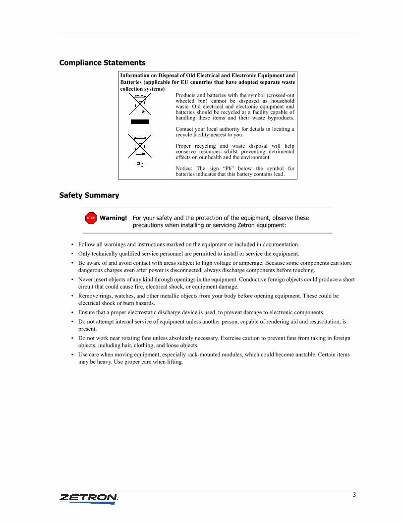
Products and batteries with the symbol (crossed-out wheeled bin) cannot be disposed as household waste. Old electrical and electronic equipment and batteries should be recycled at a facility capable of handling these items and their waste byproducts.
Contact your local authority for details in locating a recycle facility nearest to you.
Proper recycling and waste disposal will help conserve resources whilst preventing detrimental effects on our health and the environment.
Notice: The sign “Pb” below the symbol for batteries indicates that this battery contains lead.
Information on Disposal of Old Electrical and Electronic Equipment and Batteries (applicable for EU countries that have adopted separate waste collection systems)
STOP
4 025-9529P
Change List for Rev P, 25 August 2011
• Added several CAD tone options, starting with EnablePCTonesToMonSpk1=True/False on page 351
• Added a note to No Time Updates on page 247
• Updated table in SNMP Traps on page 421 to mention that rack types are now included
• Several updates to [Local Digital Inputs] on page 356
• Updated ISDN Interface on page 115
• Updated DFSI Tab on page 106 for new labels and to add Tx Audio Format.
• Updated To add or edit a Profile entry on page 301 to reflect new tabbed design for Acom Profile Management
• Updated LocalGPDigitalInputX=Function on page 356 with new options.
• Updated ZFD Installation on page 390 to reflect that ZFD is now part of the Acom Console Software installer.
• Added the following new sections:
• Trunking Groups on page 96
• MAC Addresses on page 209
• ShowEmergencyAlertClearButton=True/False on page 339
• RememberScreenPositions=True/False on page 339
• AVCX=text on page 330
• AllowIntercomsDuringPhoneCall=True on page 349
• CommsRetryDelay=500 on page 336
• Close the Copy form if there are no errors on page 394 and related screen shot on page 394
• EIU Card Options on page 215
• Appendix B: Voter Serial Interface on page 377
• [Dedicated Lines] on page 342
• Deprecated or removed:
• SplitRadioPhoneAudio=True/False on page 351
• Appendix B: Entity Management replaced by the Acom Entity Manager manual (P/N 025-9653)

Contents
5
Contents
Getting Started . . . . . . . . . . . . . . . . . . . . . . . . . . . . . . . . . . . . . . . . . . . . . . 15Associated Manuals . . . . . . . . . . . . . . . . . . . . . . . . . . . . . . . . . . . . . . . . . . . . . . . . . . . . . 15Using This Manual . . . . . . . . . . . . . . . . . . . . . . . . . . . . . . . . . . . . . . . . . . . . . . . . . . . . . 16Software Installation Order . . . . . . . . . . . . . . . . . . . . . . . . . . . . . . . . . . . . . . . . . . . . . . . 16Supported Software and Firmware Versions . . . . . . . . . . . . . . . . . . . . . . . . . . . . . . . . . . . . 17
Console Software Suite. . . . . . . . . . . . . . . . . . . . . . . . . . . . . . . . . . . . . . . . . . . . . . . . 17Integrated Management System (IMS) Software Suite. . . . . . . . . . . . . . . . . . . . . . . . . . 18Firmware . . . . . . . . . . . . . . . . . . . . . . . . . . . . . . . . . . . . . . . . . . . . . . . . . . . . . . . . . 18
Configuring Acom Line Subracks with the IMS ALS Module . . . . . . . . . . . 19Getting Started . . . . . . . . . . . . . . . . . . . . . . . . . . . . . . . . . . . . . . . . . . . . . . . . . . . . . . . . 20
Supported Cards . . . . . . . . . . . . . . . . . . . . . . . . . . . . . . . . . . . . . . . . . . . . . . . . . . . . 20Using IMS ALS with or without IMS Terminal . . . . . . . . . . . . . . . . . . . . . . . . . . . . . . . . 21Main Window . . . . . . . . . . . . . . . . . . . . . . . . . . . . . . . . . . . . . . . . . . . . . . . . . . . . . . 22Running the Program . . . . . . . . . . . . . . . . . . . . . . . . . . . . . . . . . . . . . . . . . . . . . . . . . 23
Managing Configurations (File Menu) . . . . . . . . . . . . . . . . . . . . . . . . . . . . . . . . . . . . . . . . 25Save To Disk . . . . . . . . . . . . . . . . . . . . . . . . . . . . . . . . . . . . . . . . . . . . . . . . . . . . . . . 26Load From Disk . . . . . . . . . . . . . . . . . . . . . . . . . . . . . . . . . . . . . . . . . . . . . . . . . . . . . 26Save To Router . . . . . . . . . . . . . . . . . . . . . . . . . . . . . . . . . . . . . . . . . . . . . . . . . . . . . 27Load From Router . . . . . . . . . . . . . . . . . . . . . . . . . . . . . . . . . . . . . . . . . . . . . . . . . . . 27Update to Rack . . . . . . . . . . . . . . . . . . . . . . . . . . . . . . . . . . . . . . . . . . . . . . . . . . . . . 27Firmware Upgrade . . . . . . . . . . . . . . . . . . . . . . . . . . . . . . . . . . . . . . . . . . . . . . . . . . . 28Exit . . . . . . . . . . . . . . . . . . . . . . . . . . . . . . . . . . . . . . . . . . . . . . . . . . . . . . . . . . . . . 28
Communicating with the Subrack (Communication Menu) . . . . . . . . . . . . . . . . . . . . . . . . . . 28Connect . . . . . . . . . . . . . . . . . . . . . . . . . . . . . . . . . . . . . . . . . . . . . . . . . . . . . . . . . . 28Disconnect . . . . . . . . . . . . . . . . . . . . . . . . . . . . . . . . . . . . . . . . . . . . . . . . . . . . . . . . 30Setting . . . . . . . . . . . . . . . . . . . . . . . . . . . . . . . . . . . . . . . . . . . . . . . . . . . . . . . . . . . 30Debug . . . . . . . . . . . . . . . . . . . . . . . . . . . . . . . . . . . . . . . . . . . . . . . . . . . . . . . . . . . 30
Configuring ALS Parameters (Configure Menu) . . . . . . . . . . . . . . . . . . . . . . . . . . . . . . . . . 32Set Address. . . . . . . . . . . . . . . . . . . . . . . . . . . . . . . . . . . . . . . . . . . . . . . . . . . . . . . . 32Clock . . . . . . . . . . . . . . . . . . . . . . . . . . . . . . . . . . . . . . . . . . . . . . . . . . . . . . . . . . . . 32Change Password . . . . . . . . . . . . . . . . . . . . . . . . . . . . . . . . . . . . . . . . . . . . . . . . . . . 33System . . . . . . . . . . . . . . . . . . . . . . . . . . . . . . . . . . . . . . . . . . . . . . . . . . . . . . . . . . . 34RVA Sequencing . . . . . . . . . . . . . . . . . . . . . . . . . . . . . . . . . . . . . . . . . . . . . . . . . . . . 34PTT Load Parameters . . . . . . . . . . . . . . . . . . . . . . . . . . . . . . . . . . . . . . . . . . . . . . . . . 37Radio Tone Database . . . . . . . . . . . . . . . . . . . . . . . . . . . . . . . . . . . . . . . . . . . . . . . . . 38Function Data . . . . . . . . . . . . . . . . . . . . . . . . . . . . . . . . . . . . . . . . . . . . . . . . . . . . . . 40
Contents
6 025-9529P
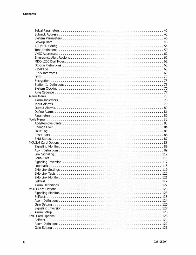
Selcal Parameters . . . . . . . . . . . . . . . . . . . . . . . . . . . . . . . . . . . . . . . . . . . . . . . . . . . . 42Subrack Address . . . . . . . . . . . . . . . . . . . . . . . . . . . . . . . . . . . . . . . . . . . . . . . . . . . . . 45System Parameters . . . . . . . . . . . . . . . . . . . . . . . . . . . . . . . . . . . . . . . . . . . . . . . . . . . 46Lookup Data . . . . . . . . . . . . . . . . . . . . . . . . . . . . . . . . . . . . . . . . . . . . . . . . . . . . . . . . 48ACD/LED Config . . . . . . . . . . . . . . . . . . . . . . . . . . . . . . . . . . . . . . . . . . . . . . . . . . . . . 54Tone Definitions . . . . . . . . . . . . . . . . . . . . . . . . . . . . . . . . . . . . . . . . . . . . . . . . . . . . . 59VNIC Addresses. . . . . . . . . . . . . . . . . . . . . . . . . . . . . . . . . . . . . . . . . . . . . . . . . . . . . . 62Emergency Alert Regions . . . . . . . . . . . . . . . . . . . . . . . . . . . . . . . . . . . . . . . . . . . . . . . 62MDC-1200 Dial Types . . . . . . . . . . . . . . . . . . . . . . . . . . . . . . . . . . . . . . . . . . . . . . . . . . 62GE-Star Definitions . . . . . . . . . . . . . . . . . . . . . . . . . . . . . . . . . . . . . . . . . . . . . . . . . . . 63P25/DFSI . . . . . . . . . . . . . . . . . . . . . . . . . . . . . . . . . . . . . . . . . . . . . . . . . . . . . . . . . . 65RFSS Interfaces. . . . . . . . . . . . . . . . . . . . . . . . . . . . . . . . . . . . . . . . . . . . . . . . . . . . . . 69DFSI. . . . . . . . . . . . . . . . . . . . . . . . . . . . . . . . . . . . . . . . . . . . . . . . . . . . . . . . . . . . . . 72Encryption . . . . . . . . . . . . . . . . . . . . . . . . . . . . . . . . . . . . . . . . . . . . . . . . . . . . . . . . . 73Station Id Definitions . . . . . . . . . . . . . . . . . . . . . . . . . . . . . . . . . . . . . . . . . . . . . . . . . . 75System Clocking . . . . . . . . . . . . . . . . . . . . . . . . . . . . . . . . . . . . . . . . . . . . . . . . . . . . . 76Ring Cadence . . . . . . . . . . . . . . . . . . . . . . . . . . . . . . . . . . . . . . . . . . . . . . . . . . . . . . . 77
Alarm Menu . . . . . . . . . . . . . . . . . . . . . . . . . . . . . . . . . . . . . . . . . . . . . . . . . . . . . . . . . . . 78Alarm Indicators . . . . . . . . . . . . . . . . . . . . . . . . . . . . . . . . . . . . . . . . . . . . . . . . . . . . . 78Input Alarms . . . . . . . . . . . . . . . . . . . . . . . . . . . . . . . . . . . . . . . . . . . . . . . . . . . . . . . . 79Output Alarms. . . . . . . . . . . . . . . . . . . . . . . . . . . . . . . . . . . . . . . . . . . . . . . . . . . . . . . 80Define Alarms . . . . . . . . . . . . . . . . . . . . . . . . . . . . . . . . . . . . . . . . . . . . . . . . . . . . . . . 81Parameters . . . . . . . . . . . . . . . . . . . . . . . . . . . . . . . . . . . . . . . . . . . . . . . . . . . . . . . . . 82
Tools Menu . . . . . . . . . . . . . . . . . . . . . . . . . . . . . . . . . . . . . . . . . . . . . . . . . . . . . . . . . . . 83Add/Remove Cards . . . . . . . . . . . . . . . . . . . . . . . . . . . . . . . . . . . . . . . . . . . . . . . . . . . 83Change Over. . . . . . . . . . . . . . . . . . . . . . . . . . . . . . . . . . . . . . . . . . . . . . . . . . . . . . . . 84Fault Log . . . . . . . . . . . . . . . . . . . . . . . . . . . . . . . . . . . . . . . . . . . . . . . . . . . . . . . . . . 85Reset Rack . . . . . . . . . . . . . . . . . . . . . . . . . . . . . . . . . . . . . . . . . . . . . . . . . . . . . . . . . 86SMU Status . . . . . . . . . . . . . . . . . . . . . . . . . . . . . . . . . . . . . . . . . . . . . . . . . . . . . . . . . 87
MCU3/4 Card Options . . . . . . . . . . . . . . . . . . . . . . . . . . . . . . . . . . . . . . . . . . . . . . . . . . . . 88Signaling Monitor. . . . . . . . . . . . . . . . . . . . . . . . . . . . . . . . . . . . . . . . . . . . . . . . . . . . . 89Acom Definitions . . . . . . . . . . . . . . . . . . . . . . . . . . . . . . . . . . . . . . . . . . . . . . . . . . . . . 89Link Signaling . . . . . . . . . . . . . . . . . . . . . . . . . . . . . . . . . . . . . . . . . . . . . . . . . . . . . . 112Serial Port. . . . . . . . . . . . . . . . . . . . . . . . . . . . . . . . . . . . . . . . . . . . . . . . . . . . . . . . . 115Signaling Inversion . . . . . . . . . . . . . . . . . . . . . . . . . . . . . . . . . . . . . . . . . . . . . . . . . . 117Loopback . . . . . . . . . . . . . . . . . . . . . . . . . . . . . . . . . . . . . . . . . . . . . . . . . . . . . . . . . 1182Mb Link Settings . . . . . . . . . . . . . . . . . . . . . . . . . . . . . . . . . . . . . . . . . . . . . . . . . . . 1192Mb Link Tests . . . . . . . . . . . . . . . . . . . . . . . . . . . . . . . . . . . . . . . . . . . . . . . . . . . . . 1202Mb Link Monitor. . . . . . . . . . . . . . . . . . . . . . . . . . . . . . . . . . . . . . . . . . . . . . . . . . . . 121Selftest. . . . . . . . . . . . . . . . . . . . . . . . . . . . . . . . . . . . . . . . . . . . . . . . . . . . . . . . . . . 122Alarm Definitions . . . . . . . . . . . . . . . . . . . . . . . . . . . . . . . . . . . . . . . . . . . . . . . . . . . . 122
MSU3 Card Options . . . . . . . . . . . . . . . . . . . . . . . . . . . . . . . . . . . . . . . . . . . . . . . . . . . . 123Signaling Monitor. . . . . . . . . . . . . . . . . . . . . . . . . . . . . . . . . . . . . . . . . . . . . . . . . . . . 123Selftest. . . . . . . . . . . . . . . . . . . . . . . . . . . . . . . . . . . . . . . . . . . . . . . . . . . . . . . . . . . 123Acom Definitions . . . . . . . . . . . . . . . . . . . . . . . . . . . . . . . . . . . . . . . . . . . . . . . . . . . . 124Gain Setting . . . . . . . . . . . . . . . . . . . . . . . . . . . . . . . . . . . . . . . . . . . . . . . . . . . . . . . 126Signaling Inversion . . . . . . . . . . . . . . . . . . . . . . . . . . . . . . . . . . . . . . . . . . . . . . . . . . 127Alarm Setup . . . . . . . . . . . . . . . . . . . . . . . . . . . . . . . . . . . . . . . . . . . . . . . . . . . . . . . 128
EMU Card Options . . . . . . . . . . . . . . . . . . . . . . . . . . . . . . . . . . . . . . . . . . . . . . . . . . . . . 128Selftest. . . . . . . . . . . . . . . . . . . . . . . . . . . . . . . . . . . . . . . . . . . . . . . . . . . . . . . . . . . 129Acom Definitions . . . . . . . . . . . . . . . . . . . . . . . . . . . . . . . . . . . . . . . . . . . . . . . . . . . . 129Gain Setting . . . . . . . . . . . . . . . . . . . . . . . . . . . . . . . . . . . . . . . . . . . . . . . . . . . . . . . 136
7
Contents
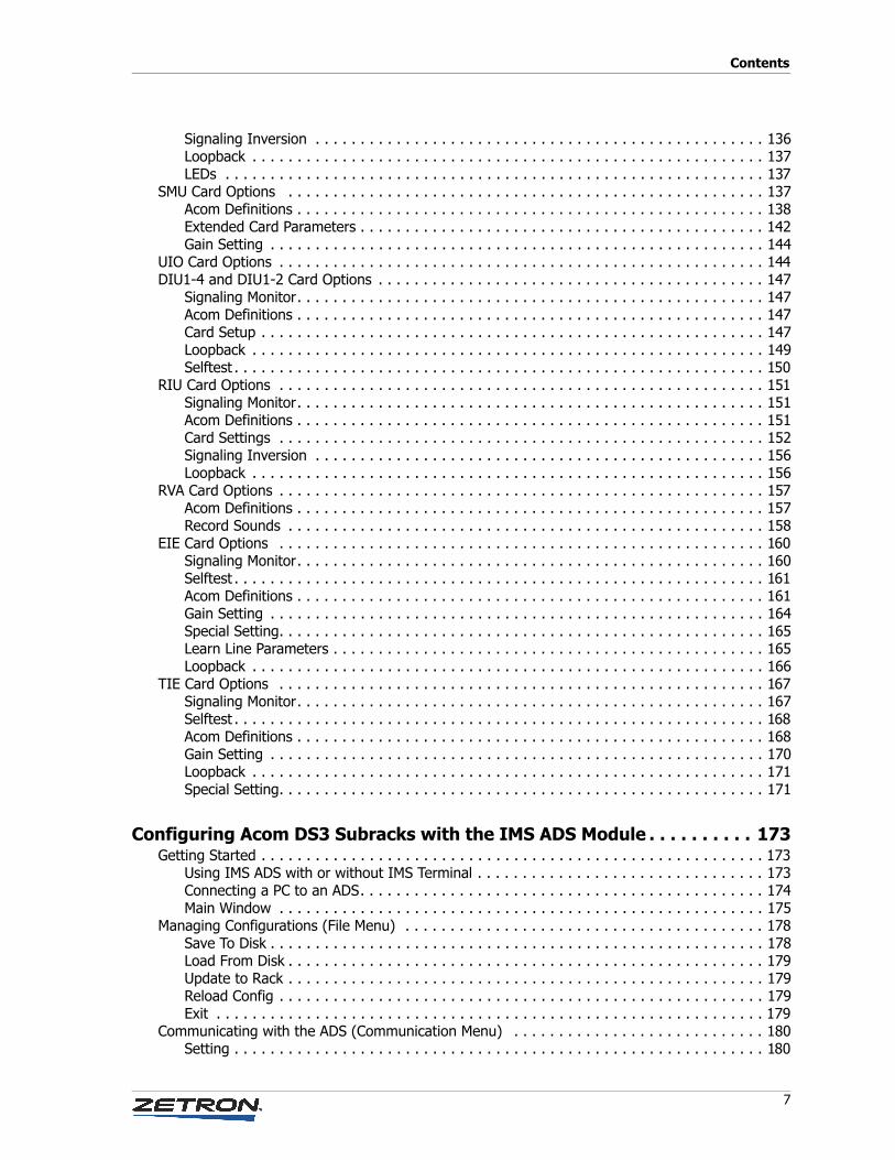
Signaling Inversion . . . . . . . . . . . . . . . . . . . . . . . . . . . . . . . . . . . . . . . . . . . . . . . . . . 136Loopback . . . . . . . . . . . . . . . . . . . . . . . . . . . . . . . . . . . . . . . . . . . . . . . . . . . . . . . . . 137LEDs . . . . . . . . . . . . . . . . . . . . . . . . . . . . . . . . . . . . . . . . . . . . . . . . . . . . . . . . . . . . 137
SMU Card Options . . . . . . . . . . . . . . . . . . . . . . . . . . . . . . . . . . . . . . . . . . . . . . . . . . . . . 137Acom Definitions . . . . . . . . . . . . . . . . . . . . . . . . . . . . . . . . . . . . . . . . . . . . . . . . . . . . 138Extended Card Parameters . . . . . . . . . . . . . . . . . . . . . . . . . . . . . . . . . . . . . . . . . . . . . 142Gain Setting . . . . . . . . . . . . . . . . . . . . . . . . . . . . . . . . . . . . . . . . . . . . . . . . . . . . . . . 144
UIO Card Options . . . . . . . . . . . . . . . . . . . . . . . . . . . . . . . . . . . . . . . . . . . . . . . . . . . . . . 144DIU1-4 and DIU1-2 Card Options . . . . . . . . . . . . . . . . . . . . . . . . . . . . . . . . . . . . . . . . . . . 147
Signaling Monitor. . . . . . . . . . . . . . . . . . . . . . . . . . . . . . . . . . . . . . . . . . . . . . . . . . . . 147Acom Definitions . . . . . . . . . . . . . . . . . . . . . . . . . . . . . . . . . . . . . . . . . . . . . . . . . . . . 147Card Setup . . . . . . . . . . . . . . . . . . . . . . . . . . . . . . . . . . . . . . . . . . . . . . . . . . . . . . . . 147Loopback . . . . . . . . . . . . . . . . . . . . . . . . . . . . . . . . . . . . . . . . . . . . . . . . . . . . . . . . . 149Selftest . . . . . . . . . . . . . . . . . . . . . . . . . . . . . . . . . . . . . . . . . . . . . . . . . . . . . . . . . . . 150
RIU Card Options . . . . . . . . . . . . . . . . . . . . . . . . . . . . . . . . . . . . . . . . . . . . . . . . . . . . . . 151Signaling Monitor. . . . . . . . . . . . . . . . . . . . . . . . . . . . . . . . . . . . . . . . . . . . . . . . . . . . 151Acom Definitions . . . . . . . . . . . . . . . . . . . . . . . . . . . . . . . . . . . . . . . . . . . . . . . . . . . . 151Card Settings . . . . . . . . . . . . . . . . . . . . . . . . . . . . . . . . . . . . . . . . . . . . . . . . . . . . . . 152Signaling Inversion . . . . . . . . . . . . . . . . . . . . . . . . . . . . . . . . . . . . . . . . . . . . . . . . . . 156Loopback . . . . . . . . . . . . . . . . . . . . . . . . . . . . . . . . . . . . . . . . . . . . . . . . . . . . . . . . . 156
RVA Card Options . . . . . . . . . . . . . . . . . . . . . . . . . . . . . . . . . . . . . . . . . . . . . . . . . . . . . . 157Acom Definitions . . . . . . . . . . . . . . . . . . . . . . . . . . . . . . . . . . . . . . . . . . . . . . . . . . . . 157Record Sounds . . . . . . . . . . . . . . . . . . . . . . . . . . . . . . . . . . . . . . . . . . . . . . . . . . . . . 158
EIE Card Options . . . . . . . . . . . . . . . . . . . . . . . . . . . . . . . . . . . . . . . . . . . . . . . . . . . . . . 160Signaling Monitor. . . . . . . . . . . . . . . . . . . . . . . . . . . . . . . . . . . . . . . . . . . . . . . . . . . . 160Selftest . . . . . . . . . . . . . . . . . . . . . . . . . . . . . . . . . . . . . . . . . . . . . . . . . . . . . . . . . . . 161Acom Definitions . . . . . . . . . . . . . . . . . . . . . . . . . . . . . . . . . . . . . . . . . . . . . . . . . . . . 161Gain Setting . . . . . . . . . . . . . . . . . . . . . . . . . . . . . . . . . . . . . . . . . . . . . . . . . . . . . . . 164Special Setting. . . . . . . . . . . . . . . . . . . . . . . . . . . . . . . . . . . . . . . . . . . . . . . . . . . . . . 165Learn Line Parameters . . . . . . . . . . . . . . . . . . . . . . . . . . . . . . . . . . . . . . . . . . . . . . . . 165Loopback . . . . . . . . . . . . . . . . . . . . . . . . . . . . . . . . . . . . . . . . . . . . . . . . . . . . . . . . . 166
TIE Card Options . . . . . . . . . . . . . . . . . . . . . . . . . . . . . . . . . . . . . . . . . . . . . . . . . . . . . . 167Signaling Monitor. . . . . . . . . . . . . . . . . . . . . . . . . . . . . . . . . . . . . . . . . . . . . . . . . . . . 167Selftest . . . . . . . . . . . . . . . . . . . . . . . . . . . . . . . . . . . . . . . . . . . . . . . . . . . . . . . . . . . 168Acom Definitions . . . . . . . . . . . . . . . . . . . . . . . . . . . . . . . . . . . . . . . . . . . . . . . . . . . . 168Gain Setting . . . . . . . . . . . . . . . . . . . . . . . . . . . . . . . . . . . . . . . . . . . . . . . . . . . . . . . 170Loopback . . . . . . . . . . . . . . . . . . . . . . . . . . . . . . . . . . . . . . . . . . . . . . . . . . . . . . . . . 171Special Setting. . . . . . . . . . . . . . . . . . . . . . . . . . . . . . . . . . . . . . . . . . . . . . . . . . . . . . 171
Configuring Acom DS3 Subracks with the IMS ADS Module . . . . . . . . . . 173Getting Started . . . . . . . . . . . . . . . . . . . . . . . . . . . . . . . . . . . . . . . . . . . . . . . . . . . . . . . . 173
Using IMS ADS with or without IMS Terminal . . . . . . . . . . . . . . . . . . . . . . . . . . . . . . . . 173Connecting a PC to an ADS. . . . . . . . . . . . . . . . . . . . . . . . . . . . . . . . . . . . . . . . . . . . . 174Main Window . . . . . . . . . . . . . . . . . . . . . . . . . . . . . . . . . . . . . . . . . . . . . . . . . . . . . . 175
Managing Configurations (File Menu) . . . . . . . . . . . . . . . . . . . . . . . . . . . . . . . . . . . . . . . . 178Save To Disk . . . . . . . . . . . . . . . . . . . . . . . . . . . . . . . . . . . . . . . . . . . . . . . . . . . . . . . 178Load From Disk . . . . . . . . . . . . . . . . . . . . . . . . . . . . . . . . . . . . . . . . . . . . . . . . . . . . . 179Update to Rack . . . . . . . . . . . . . . . . . . . . . . . . . . . . . . . . . . . . . . . . . . . . . . . . . . . . . 179Reload Config . . . . . . . . . . . . . . . . . . . . . . . . . . . . . . . . . . . . . . . . . . . . . . . . . . . . . . 179Exit . . . . . . . . . . . . . . . . . . . . . . . . . . . . . . . . . . . . . . . . . . . . . . . . . . . . . . . . . . . . . 179
Communicating with the ADS (Communication Menu) . . . . . . . . . . . . . . . . . . . . . . . . . . . . 180Setting . . . . . . . . . . . . . . . . . . . . . . . . . . . . . . . . . . . . . . . . . . . . . . . . . . . . . . . . . . . 180
Contents
8 025-9529P
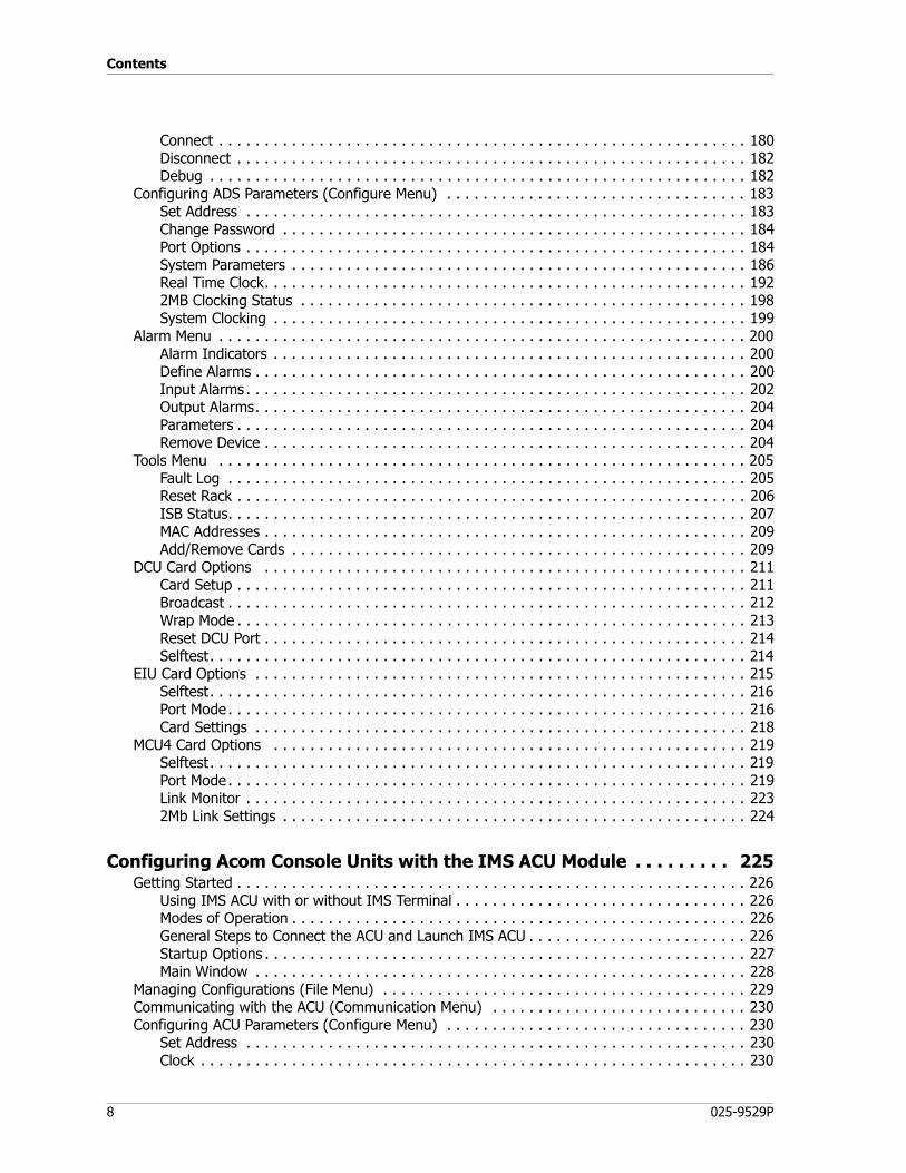
Connect . . . . . . . . . . . . . . . . . . . . . . . . . . . . . . . . . . . . . . . . . . . . . . . . . . . . . . . . . . 180Disconnect . . . . . . . . . . . . . . . . . . . . . . . . . . . . . . . . . . . . . . . . . . . . . . . . . . . . . . . . 182Debug . . . . . . . . . . . . . . . . . . . . . . . . . . . . . . . . . . . . . . . . . . . . . . . . . . . . . . . . . . . 182
Configuring ADS Parameters (Configure Menu) . . . . . . . . . . . . . . . . . . . . . . . . . . . . . . . . . 183Set Address . . . . . . . . . . . . . . . . . . . . . . . . . . . . . . . . . . . . . . . . . . . . . . . . . . . . . . . 183Change Password . . . . . . . . . . . . . . . . . . . . . . . . . . . . . . . . . . . . . . . . . . . . . . . . . . . 184Port Options . . . . . . . . . . . . . . . . . . . . . . . . . . . . . . . . . . . . . . . . . . . . . . . . . . . . . . . 184System Parameters . . . . . . . . . . . . . . . . . . . . . . . . . . . . . . . . . . . . . . . . . . . . . . . . . . 186Real Time Clock. . . . . . . . . . . . . . . . . . . . . . . . . . . . . . . . . . . . . . . . . . . . . . . . . . . . . 1922MB Clocking Status . . . . . . . . . . . . . . . . . . . . . . . . . . . . . . . . . . . . . . . . . . . . . . . . . 198System Clocking . . . . . . . . . . . . . . . . . . . . . . . . . . . . . . . . . . . . . . . . . . . . . . . . . . . . 199
Alarm Menu . . . . . . . . . . . . . . . . . . . . . . . . . . . . . . . . . . . . . . . . . . . . . . . . . . . . . . . . . . 200Alarm Indicators . . . . . . . . . . . . . . . . . . . . . . . . . . . . . . . . . . . . . . . . . . . . . . . . . . . . 200Define Alarms . . . . . . . . . . . . . . . . . . . . . . . . . . . . . . . . . . . . . . . . . . . . . . . . . . . . . . 200Input Alarms . . . . . . . . . . . . . . . . . . . . . . . . . . . . . . . . . . . . . . . . . . . . . . . . . . . . . . . 202Output Alarms. . . . . . . . . . . . . . . . . . . . . . . . . . . . . . . . . . . . . . . . . . . . . . . . . . . . . . 204Parameters . . . . . . . . . . . . . . . . . . . . . . . . . . . . . . . . . . . . . . . . . . . . . . . . . . . . . . . . 204Remove Device . . . . . . . . . . . . . . . . . . . . . . . . . . . . . . . . . . . . . . . . . . . . . . . . . . . . . 204
Tools Menu . . . . . . . . . . . . . . . . . . . . . . . . . . . . . . . . . . . . . . . . . . . . . . . . . . . . . . . . . . 205Fault Log . . . . . . . . . . . . . . . . . . . . . . . . . . . . . . . . . . . . . . . . . . . . . . . . . . . . . . . . . 205Reset Rack . . . . . . . . . . . . . . . . . . . . . . . . . . . . . . . . . . . . . . . . . . . . . . . . . . . . . . . . 206ISB Status. . . . . . . . . . . . . . . . . . . . . . . . . . . . . . . . . . . . . . . . . . . . . . . . . . . . . . . . . 207MAC Addresses . . . . . . . . . . . . . . . . . . . . . . . . . . . . . . . . . . . . . . . . . . . . . . . . . . . . . 209Add/Remove Cards . . . . . . . . . . . . . . . . . . . . . . . . . . . . . . . . . . . . . . . . . . . . . . . . . . 209
DCU Card Options . . . . . . . . . . . . . . . . . . . . . . . . . . . . . . . . . . . . . . . . . . . . . . . . . . . . . 211Card Setup . . . . . . . . . . . . . . . . . . . . . . . . . . . . . . . . . . . . . . . . . . . . . . . . . . . . . . . . 211Broadcast . . . . . . . . . . . . . . . . . . . . . . . . . . . . . . . . . . . . . . . . . . . . . . . . . . . . . . . . . 212Wrap Mode . . . . . . . . . . . . . . . . . . . . . . . . . . . . . . . . . . . . . . . . . . . . . . . . . . . . . . . . 213Reset DCU Port . . . . . . . . . . . . . . . . . . . . . . . . . . . . . . . . . . . . . . . . . . . . . . . . . . . . . 214Selftest. . . . . . . . . . . . . . . . . . . . . . . . . . . . . . . . . . . . . . . . . . . . . . . . . . . . . . . . . . . 214
EIU Card Options . . . . . . . . . . . . . . . . . . . . . . . . . . . . . . . . . . . . . . . . . . . . . . . . . . . . . . 215Selftest. . . . . . . . . . . . . . . . . . . . . . . . . . . . . . . . . . . . . . . . . . . . . . . . . . . . . . . . . . . 216Port Mode. . . . . . . . . . . . . . . . . . . . . . . . . . . . . . . . . . . . . . . . . . . . . . . . . . . . . . . . . 216Card Settings . . . . . . . . . . . . . . . . . . . . . . . . . . . . . . . . . . . . . . . . . . . . . . . . . . . . . . 218
MCU4 Card Options . . . . . . . . . . . . . . . . . . . . . . . . . . . . . . . . . . . . . . . . . . . . . . . . . . . . 219Selftest. . . . . . . . . . . . . . . . . . . . . . . . . . . . . . . . . . . . . . . . . . . . . . . . . . . . . . . . . . . 219Port Mode. . . . . . . . . . . . . . . . . . . . . . . . . . . . . . . . . . . . . . . . . . . . . . . . . . . . . . . . . 219Link Monitor . . . . . . . . . . . . . . . . . . . . . . . . . . . . . . . . . . . . . . . . . . . . . . . . . . . . . . . 2232Mb Link Settings . . . . . . . . . . . . . . . . . . . . . . . . . . . . . . . . . . . . . . . . . . . . . . . . . . . 224
Configuring Acom Console Units with the IMS ACU Module . . . . . . . . . 225Getting Started . . . . . . . . . . . . . . . . . . . . . . . . . . . . . . . . . . . . . . . . . . . . . . . . . . . . . . . . 226
Using IMS ACU with or without IMS Terminal . . . . . . . . . . . . . . . . . . . . . . . . . . . . . . . . 226Modes of Operation . . . . . . . . . . . . . . . . . . . . . . . . . . . . . . . . . . . . . . . . . . . . . . . . . . 226General Steps to Connect the ACU and Launch IMS ACU . . . . . . . . . . . . . . . . . . . . . . . . 226Startup Options . . . . . . . . . . . . . . . . . . . . . . . . . . . . . . . . . . . . . . . . . . . . . . . . . . . . . 227Main Window . . . . . . . . . . . . . . . . . . . . . . . . . . . . . . . . . . . . . . . . . . . . . . . . . . . . . . 228
Managing Configurations (File Menu) . . . . . . . . . . . . . . . . . . . . . . . . . . . . . . . . . . . . . . . . 229Communicating with the ACU (Communication Menu) . . . . . . . . . . . . . . . . . . . . . . . . . . . . 230Configuring ACU Parameters (Configure Menu) . . . . . . . . . . . . . . . . . . . . . . . . . . . . . . . . . 230
Set Address . . . . . . . . . . . . . . . . . . . . . . . . . . . . . . . . . . . . . . . . . . . . . . . . . . . . . . . 230Clock . . . . . . . . . . . . . . . . . . . . . . . . . . . . . . . . . . . . . . . . . . . . . . . . . . . . . . . . . . . . 230
9
Contents
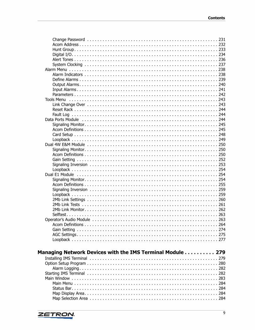
Change Password . . . . . . . . . . . . . . . . . . . . . . . . . . . . . . . . . . . . . . . . . . . . . . . . . . . 231Acom Address . . . . . . . . . . . . . . . . . . . . . . . . . . . . . . . . . . . . . . . . . . . . . . . . . . . . . . 232Hunt Group . . . . . . . . . . . . . . . . . . . . . . . . . . . . . . . . . . . . . . . . . . . . . . . . . . . . . . . . 233Digital I/O. . . . . . . . . . . . . . . . . . . . . . . . . . . . . . . . . . . . . . . . . . . . . . . . . . . . . . . . . 234Alert Tones . . . . . . . . . . . . . . . . . . . . . . . . . . . . . . . . . . . . . . . . . . . . . . . . . . . . . . . . 236System Clocking . . . . . . . . . . . . . . . . . . . . . . . . . . . . . . . . . . . . . . . . . . . . . . . . . . . . 237
Alarm Menu . . . . . . . . . . . . . . . . . . . . . . . . . . . . . . . . . . . . . . . . . . . . . . . . . . . . . . . . . . 238Alarm Indicators . . . . . . . . . . . . . . . . . . . . . . . . . . . . . . . . . . . . . . . . . . . . . . . . . . . . 238Define Alarms . . . . . . . . . . . . . . . . . . . . . . . . . . . . . . . . . . . . . . . . . . . . . . . . . . . . . . 239Output Alarms . . . . . . . . . . . . . . . . . . . . . . . . . . . . . . . . . . . . . . . . . . . . . . . . . . . . . . 240Input Alarms . . . . . . . . . . . . . . . . . . . . . . . . . . . . . . . . . . . . . . . . . . . . . . . . . . . . . . . 241Parameters . . . . . . . . . . . . . . . . . . . . . . . . . . . . . . . . . . . . . . . . . . . . . . . . . . . . . . . . 242
Tools Menu . . . . . . . . . . . . . . . . . . . . . . . . . . . . . . . . . . . . . . . . . . . . . . . . . . . . . . . . . . 243Link Change Over . . . . . . . . . . . . . . . . . . . . . . . . . . . . . . . . . . . . . . . . . . . . . . . . . . . 243Reset Rack . . . . . . . . . . . . . . . . . . . . . . . . . . . . . . . . . . . . . . . . . . . . . . . . . . . . . . . . 244Fault Log . . . . . . . . . . . . . . . . . . . . . . . . . . . . . . . . . . . . . . . . . . . . . . . . . . . . . . . . . 244
Data Ports Module . . . . . . . . . . . . . . . . . . . . . . . . . . . . . . . . . . . . . . . . . . . . . . . . . . . . . 244Signaling Monitor. . . . . . . . . . . . . . . . . . . . . . . . . . . . . . . . . . . . . . . . . . . . . . . . . . . . 245Acom Definitions . . . . . . . . . . . . . . . . . . . . . . . . . . . . . . . . . . . . . . . . . . . . . . . . . . . . 245Card Setup . . . . . . . . . . . . . . . . . . . . . . . . . . . . . . . . . . . . . . . . . . . . . . . . . . . . . . . . 248Loopback . . . . . . . . . . . . . . . . . . . . . . . . . . . . . . . . . . . . . . . . . . . . . . . . . . . . . . . . . 249
Dual 4W E&M Module . . . . . . . . . . . . . . . . . . . . . . . . . . . . . . . . . . . . . . . . . . . . . . . . . . . 250Signaling Monitor. . . . . . . . . . . . . . . . . . . . . . . . . . . . . . . . . . . . . . . . . . . . . . . . . . . . 250Acom Definitions . . . . . . . . . . . . . . . . . . . . . . . . . . . . . . . . . . . . . . . . . . . . . . . . . . . . 250Gain Setting . . . . . . . . . . . . . . . . . . . . . . . . . . . . . . . . . . . . . . . . . . . . . . . . . . . . . . . 252Signaling Inversion . . . . . . . . . . . . . . . . . . . . . . . . . . . . . . . . . . . . . . . . . . . . . . . . . . 253Loopback . . . . . . . . . . . . . . . . . . . . . . . . . . . . . . . . . . . . . . . . . . . . . . . . . . . . . . . . . 254
Dual E1 Module . . . . . . . . . . . . . . . . . . . . . . . . . . . . . . . . . . . . . . . . . . . . . . . . . . . . . . . 254Signaling Monitor. . . . . . . . . . . . . . . . . . . . . . . . . . . . . . . . . . . . . . . . . . . . . . . . . . . . 254Acom Definitions . . . . . . . . . . . . . . . . . . . . . . . . . . . . . . . . . . . . . . . . . . . . . . . . . . . . 255Signaling Inversion . . . . . . . . . . . . . . . . . . . . . . . . . . . . . . . . . . . . . . . . . . . . . . . . . . 259Loopback . . . . . . . . . . . . . . . . . . . . . . . . . . . . . . . . . . . . . . . . . . . . . . . . . . . . . . . . . 2592Mb Link Settings . . . . . . . . . . . . . . . . . . . . . . . . . . . . . . . . . . . . . . . . . . . . . . . . . . . 2602Mb Link Tests . . . . . . . . . . . . . . . . . . . . . . . . . . . . . . . . . . . . . . . . . . . . . . . . . . . . . 2612Mb Link Monitor. . . . . . . . . . . . . . . . . . . . . . . . . . . . . . . . . . . . . . . . . . . . . . . . . . . . 262Selftest . . . . . . . . . . . . . . . . . . . . . . . . . . . . . . . . . . . . . . . . . . . . . . . . . . . . . . . . . . . 263
Operator’s Audio Module . . . . . . . . . . . . . . . . . . . . . . . . . . . . . . . . . . . . . . . . . . . . . . . . . 263Acom Definitions . . . . . . . . . . . . . . . . . . . . . . . . . . . . . . . . . . . . . . . . . . . . . . . . . . . . 264Gain Setting . . . . . . . . . . . . . . . . . . . . . . . . . . . . . . . . . . . . . . . . . . . . . . . . . . . . . . . 274AGC Settings . . . . . . . . . . . . . . . . . . . . . . . . . . . . . . . . . . . . . . . . . . . . . . . . . . . . . . . 275Loopback . . . . . . . . . . . . . . . . . . . . . . . . . . . . . . . . . . . . . . . . . . . . . . . . . . . . . . . . . 277
Managing Network Devices with the IMS Terminal Module . . . . . . . . . . 279Installing IMS Terminal . . . . . . . . . . . . . . . . . . . . . . . . . . . . . . . . . . . . . . . . . . . . . . . . . . 279Option Setup Program . . . . . . . . . . . . . . . . . . . . . . . . . . . . . . . . . . . . . . . . . . . . . . . . . . . 280
Alarm Logging . . . . . . . . . . . . . . . . . . . . . . . . . . . . . . . . . . . . . . . . . . . . . . . . . . . . . . 282Starting IMS Terminal . . . . . . . . . . . . . . . . . . . . . . . . . . . . . . . . . . . . . . . . . . . . . . . . . . . 282Main Window . . . . . . . . . . . . . . . . . . . . . . . . . . . . . . . . . . . . . . . . . . . . . . . . . . . . . . . . . 283
Main Menu . . . . . . . . . . . . . . . . . . . . . . . . . . . . . . . . . . . . . . . . . . . . . . . . . . . . . . . . 284Status Bar. . . . . . . . . . . . . . . . . . . . . . . . . . . . . . . . . . . . . . . . . . . . . . . . . . . . . . . . . 284Map Display Area. . . . . . . . . . . . . . . . . . . . . . . . . . . . . . . . . . . . . . . . . . . . . . . . . . . . 284Map Selection Area . . . . . . . . . . . . . . . . . . . . . . . . . . . . . . . . . . . . . . . . . . . . . . . . . . 284
Contents
10 025-9529P
Logging On and Off . . . . . . . . . . . . . . . . . . . . . . . . . . . . . . . . . . . . . . . . . . . . . . . . . . . . 285Locking the Console . . . . . . . . . . . . . . . . . . . . . . . . . . . . . . . . . . . . . . . . . . . . . . . . . . . . 285System Map Setup . . . . . . . . . . . . . . . . . . . . . . . . . . . . . . . . . . . . . . . . . . . . . . . . . . . . . 285
Using the Map Builder . . . . . . . . . . . . . . . . . . . . . . . . . . . . . . . . . . . . . . . . . . . . . . . . 286Send to Router . . . . . . . . . . . . . . . . . . . . . . . . . . . . . . . . . . . . . . . . . . . . . . . . . . . . . 288Retrieve from Router . . . . . . . . . . . . . . . . . . . . . . . . . . . . . . . . . . . . . . . . . . . . . . . . . 289
Tools . . . . . . . . . . . . . . . . . . . . . . . . . . . . . . . . . . . . . . . . . . . . . . . . . . . . . . . . . . . . . . . 289Find Device . . . . . . . . . . . . . . . . . . . . . . . . . . . . . . . . . . . . . . . . . . . . . . . . . . . . . . . . 289Find Map . . . . . . . . . . . . . . . . . . . . . . . . . . . . . . . . . . . . . . . . . . . . . . . . . . . . . . . . . 290Send File . . . . . . . . . . . . . . . . . . . . . . . . . . . . . . . . . . . . . . . . . . . . . . . . . . . . . . . . . 290Receive File. . . . . . . . . . . . . . . . . . . . . . . . . . . . . . . . . . . . . . . . . . . . . . . . . . . . . . . . 290Refresh All Files. . . . . . . . . . . . . . . . . . . . . . . . . . . . . . . . . . . . . . . . . . . . . . . . . . . . . 290
Configuration . . . . . . . . . . . . . . . . . . . . . . . . . . . . . . . . . . . . . . . . . . . . . . . . . . . . . . . . . 290Show Alarms. . . . . . . . . . . . . . . . . . . . . . . . . . . . . . . . . . . . . . . . . . . . . . . . . . . . . . . 290Print Alarms . . . . . . . . . . . . . . . . . . . . . . . . . . . . . . . . . . . . . . . . . . . . . . . . . . . . . . . 291Users . . . . . . . . . . . . . . . . . . . . . . . . . . . . . . . . . . . . . . . . . . . . . . . . . . . . . . . . . . . . 291Add New User . . . . . . . . . . . . . . . . . . . . . . . . . . . . . . . . . . . . . . . . . . . . . . . . . . . . . . 292Edit User . . . . . . . . . . . . . . . . . . . . . . . . . . . . . . . . . . . . . . . . . . . . . . . . . . . . . . . . . 292
Alarms . . . . . . . . . . . . . . . . . . . . . . . . . . . . . . . . . . . . . . . . . . . . . . . . . . . . . . . . . . . . . . 293
Console Applications and Administrative Tools . . . . . . . . . . . . . . . . . . . 295Windows 7 Configuration . . . . . . . . . . . . . . . . . . . . . . . . . . . . . . . . . . . . . . . . . . . . . . . . 295
Windows 7 User Account Control. . . . . . . . . . . . . . . . . . . . . . . . . . . . . . . . . . . . . . . . . 295Windows 7 Touchscreen . . . . . . . . . . . . . . . . . . . . . . . . . . . . . . . . . . . . . . . . . . . . . . . 296
Console Applications . . . . . . . . . . . . . . . . . . . . . . . . . . . . . . . . . . . . . . . . . . . . . . . . . . . . 296Administrative Tools . . . . . . . . . . . . . . . . . . . . . . . . . . . . . . . . . . . . . . . . . . . . . . . . . . . . 297Installation Order . . . . . . . . . . . . . . . . . . . . . . . . . . . . . . . . . . . . . . . . . . . . . . . . . . . . . . 297User Management System (UMS) . . . . . . . . . . . . . . . . . . . . . . . . . . . . . . . . . . . . . . . . . . . 297
Establishing Permissions. . . . . . . . . . . . . . . . . . . . . . . . . . . . . . . . . . . . . . . . . . . . . . . 298Acom Console Software (ACS) . . . . . . . . . . . . . . . . . . . . . . . . . . . . . . . . . . . . . . . . . . . . . 298Text Messaging . . . . . . . . . . . . . . . . . . . . . . . . . . . . . . . . . . . . . . . . . . . . . . . . . . . . . . . 299Database of Operators . . . . . . . . . . . . . . . . . . . . . . . . . . . . . . . . . . . . . . . . . . . . . . . . . . 299Paging Configuration . . . . . . . . . . . . . . . . . . . . . . . . . . . . . . . . . . . . . . . . . . . . . . . . . . . . 307
New Configuration File Format . . . . . . . . . . . . . . . . . . . . . . . . . . . . . . . . . . . . . . . . . . 308Page Global. . . . . . . . . . . . . . . . . . . . . . . . . . . . . . . . . . . . . . . . . . . . . . . . . . . . . . . . 308Page Format . . . . . . . . . . . . . . . . . . . . . . . . . . . . . . . . . . . . . . . . . . . . . . . . . . . . . . . 309Instant Pages . . . . . . . . . . . . . . . . . . . . . . . . . . . . . . . . . . . . . . . . . . . . . . . . . . . . . . 318M25ES Option . . . . . . . . . . . . . . . . . . . . . . . . . . . . . . . . . . . . . . . . . . . . . . . . . . . . . . 323
Subscriber Configuration . . . . . . . . . . . . . . . . . . . . . . . . . . . . . . . . . . . . . . . . . . . . . . . . . 324
Appendix A: Acom Console Software Configuration File (AcomConsole.ini). 327
Overview . . . . . . . . . . . . . . . . . . . . . . . . . . . . . . . . . . . . . . . . . . . . . . . . . . . . . . . . . . . . 327[ACD Area Names] . . . . . . . . . . . . . . . . . . . . . . . . . . . . . . . . . . . . . . . . . . . . . . . . . . . . . 328[ACD Queue Names] . . . . . . . . . . . . . . . . . . . . . . . . . . . . . . . . . . . . . . . . . . . . . . . . . . . . 328[Acom Updates] . . . . . . . . . . . . . . . . . . . . . . . . . . . . . . . . . . . . . . . . . . . . . . . . . . . . . . . 328[Alarms] . . . . . . . . . . . . . . . . . . . . . . . . . . . . . . . . . . . . . . . . . . . . . . . . . . . . . . . . . . . . 329[Avcall] . . . . . . . . . . . . . . . . . . . . . . . . . . . . . . . . . . . . . . . . . . . . . . . . . . . . . . . . . . . . . 331[Call History] . . . . . . . . . . . . . . . . . . . . . . . . . . . . . . . . . . . . . . . . . . . . . . . . . . . . . . . . . 331[Call Transfer] . . . . . . . . . . . . . . . . . . . . . . . . . . . . . . . . . . . . . . . . . . . . . . . . . . . . . . . . 332[Clean Touch Screen] . . . . . . . . . . . . . . . . . . . . . . . . . . . . . . . . . . . . . . . . . . . . . . . . . . . 333
11
Contents
[Colors] . . . . . . . . . . . . . . . . . . . . . . . . . . . . . . . . . . . . . . . . . . . . . . . . . . . . . . . . . . . . . 333[Communications] . . . . . . . . . . . . . . . . . . . . . . . . . . . . . . . . . . . . . . . . . . . . . . . . . . . . . 336[Conference] . . . . . . . . . . . . . . . . . . . . . . . . . . . . . . . . . . . . . . . . . . . . . . . . . . . . . . . . . 337[Console] . . . . . . . . . . . . . . . . . . . . . . . . . . . . . . . . . . . . . . . . . . . . . . . . . . . . . . . . . . . . 337[Console Groups] . . . . . . . . . . . . . . . . . . . . . . . . . . . . . . . . . . . . . . . . . . . . . . . . . . . . . . 340[Console Intrude] . . . . . . . . . . . . . . . . . . . . . . . . . . . . . . . . . . . . . . . . . . . . . . . . . . . . . . 341[Console PTT Active] . . . . . . . . . . . . . . . . . . . . . . . . . . . . . . . . . . . . . . . . . . . . . . . . . . . . 341[Console Ring] . . . . . . . . . . . . . . . . . . . . . . . . . . . . . . . . . . . . . . . . . . . . . . . . . . . . . . . . 341[Consoles] . . . . . . . . . . . . . . . . . . . . . . . . . . . . . . . . . . . . . . . . . . . . . . . . . . . . . . . . . . . 342[Cursors] . . . . . . . . . . . . . . . . . . . . . . . . . . . . . . . . . . . . . . . . . . . . . . . . . . . . . . . . . . . . 342[Dedicated Lines] . . . . . . . . . . . . . . . . . . . . . . . . . . . . . . . . . . . . . . . . . . . . . . . . . . . . . . 342[Dial Pad] . . . . . . . . . . . . . . . . . . . . . . . . . . . . . . . . . . . . . . . . . . . . . . . . . . . . . . . . . . . 343[Digital Outputs] . . . . . . . . . . . . . . . . . . . . . . . . . . . . . . . . . . . . . . . . . . . . . . . . . . . . . . . 344[Fast Keys] . . . . . . . . . . . . . . . . . . . . . . . . . . . . . . . . . . . . . . . . . . . . . . . . . . . . . . . . . . . 345[GE-Star] . . . . . . . . . . . . . . . . . . . . . . . . . . . . . . . . . . . . . . . . . . . . . . . . . . . . . . . . . . . . 347[Incoming Call Queue] . . . . . . . . . . . . . . . . . . . . . . . . . . . . . . . . . . . . . . . . . . . . . . . . . . 347[Incoming Calls] . . . . . . . . . . . . . . . . . . . . . . . . . . . . . . . . . . . . . . . . . . . . . . . . . . . . . . . 348[Initial Level] . . . . . . . . . . . . . . . . . . . . . . . . . . . . . . . . . . . . . . . . . . . . . . . . . . . . . . . . . 348[Intercoms] . . . . . . . . . . . . . . . . . . . . . . . . . . . . . . . . . . . . . . . . . . . . . . . . . . . . . . . . . . 349[Interfaces] . . . . . . . . . . . . . . . . . . . . . . . . . . . . . . . . . . . . . . . . . . . . . . . . . . . . . . . . . . 349[IRR] . . . . . . . . . . . . . . . . . . . . . . . . . . . . . . . . . . . . . . . . . . . . . . . . . . . . . . . . . . . . . . . 353[Line Groups] . . . . . . . . . . . . . . . . . . . . . . . . . . . . . . . . . . . . . . . . . . . . . . . . . . . . . . . . . 354[Line Selection] . . . . . . . . . . . . . . . . . . . . . . . . . . . . . . . . . . . . . . . . . . . . . . . . . . . . . . . 354[Line Volume] . . . . . . . . . . . . . . . . . . . . . . . . . . . . . . . . . . . . . . . . . . . . . . . . . . . . . . . . 356[Local Digital Inputs] . . . . . . . . . . . . . . . . . . . . . . . . . . . . . . . . . . . . . . . . . . . . . . . . . . . 356[Local Digital Outputs] . . . . . . . . . . . . . . . . . . . . . . . . . . . . . . . . . . . . . . . . . . . . . . . . . . 357[MDC] . . . . . . . . . . . . . . . . . . . . . . . . . . . . . . . . . . . . . . . . . . . . . . . . . . . . . . . . . . . . . . 358[Monitor] . . . . . . . . . . . . . . . . . . . . . . . . . . . . . . . . . . . . . . . . . . . . . . . . . . . . . . . . . . . . 359[Mouse] . . . . . . . . . . . . . . . . . . . . . . . . . . . . . . . . . . . . . . . . . . . . . . . . . . . . . . . . . . . . . 359[Paging] . . . . . . . . . . . . . . . . . . . . . . . . . . . . . . . . . . . . . . . . . . . . . . . . . . . . . . . . . . . . 359[Ports] . . . . . . . . . . . . . . . . . . . . . . . . . . . . . . . . . . . . . . . . . . . . . . . . . . . . . . . . . . . . . . 361[Queue Box] . . . . . . . . . . . . . . . . . . . . . . . . . . . . . . . . . . . . . . . . . . . . . . . . . . . . . . . . . 361[Radio Lines] . . . . . . . . . . . . . . . . . . . . . . . . . . . . . . . . . . . . . . . . . . . . . . . . . . . . . . . . . 363[Screen Positions] . . . . . . . . . . . . . . . . . . . . . . . . . . . . . . . . . . . . . . . . . . . . . . . . . . . . . . 365[Screens] . . . . . . . . . . . . . . . . . . . . . . . . . . . . . . . . . . . . . . . . . . . . . . . . . . . . . . . . . . . . 366[Selcal] . . . . . . . . . . . . . . . . . . . . . . . . . . . . . . . . . . . . . . . . . . . . . . . . . . . . . . . . . . . . . 367[Sounds] . . . . . . . . . . . . . . . . . . . . . . . . . . . . . . . . . . . . . . . . . . . . . . . . . . . . . . . . . . . . 368[Talker IDs] . . . . . . . . . . . . . . . . . . . . . . . . . . . . . . . . . . . . . . . . . . . . . . . . . . . . . . . . . . 371[Telephone Lines] . . . . . . . . . . . . . . . . . . . . . . . . . . . . . . . . . . . . . . . . . . . . . . . . . . . . . . 372[Timeout Periods] . . . . . . . . . . . . . . . . . . . . . . . . . . . . . . . . . . . . . . . . . . . . . . . . . . . . . . 373[UMS] . . . . . . . . . . . . . . . . . . . . . . . . . . . . . . . . . . . . . . . . . . . . . . . . . . . . . . . . . . . . . . 374[UMS.Screens] . . . . . . . . . . . . . . . . . . . . . . . . . . . . . . . . . . . . . . . . . . . . . . . . . . . . . . . . 374[User Defined Line Groups] . . . . . . . . . . . . . . . . . . . . . . . . . . . . . . . . . . . . . . . . . . . . . . . 375
Appendix B: Voter Serial Interface . . . . . . . . . . . . . . . . . . . . . . . . . . . . . . 377Overview . . . . . . . . . . . . . . . . . . . . . . . . . . . . . . . . . . . . . . . . . . . . . . . . . . . . . . . . . . . . 377User Interface Design and Console Operation . . . . . . . . . . . . . . . . . . . . . . . . . . . . . . . . . . 377ACOM Setup . . . . . . . . . . . . . . . . . . . . . . . . . . . . . . . . . . . . . . . . . . . . . . . . . . . . . . . . . 382
Physical Connection . . . . . . . . . . . . . . . . . . . . . . . . . . . . . . . . . . . . . . . . . . . . . . . . . . 382Acom Definitions . . . . . . . . . . . . . . . . . . . . . . . . . . . . . . . . . . . . . . . . . . . . . . . . . . . . 383
JPS Voter Simulator . . . . . . . . . . . . . . . . . . . . . . . . . . . . . . . . . . . . . . . . . . . . . . . . . . . . 384Troubleshooting . . . . . . . . . . . . . . . . . . . . . . . . . . . . . . . . . . . . . . . . . . . . . . . . . . . . . . . 386
Contents
12 025-9529P
Debug Commands . . . . . . . . . . . . . . . . . . . . . . . . . . . . . . . . . . . . . . . . . . . . . . . . . . . 386Fault Logs . . . . . . . . . . . . . . . . . . . . . . . . . . . . . . . . . . . . . . . . . . . . . . . . . . . . . . . . . 387
Appendix C: Distributing Console Files . . . . . . . . . . . . . . . . . . . . . . . . . . 389Overview . . . . . . . . . . . . . . . . . . . . . . . . . . . . . . . . . . . . . . . . . . . . . . . . . . . . . . . . . . . . 389Installation . . . . . . . . . . . . . . . . . . . . . . . . . . . . . . . . . . . . . . . . . . . . . . . . . . . . . . . . . . 390
Initial Startup . . . . . . . . . . . . . . . . . . . . . . . . . . . . . . . . . . . . . . . . . . . . . . . . . . . . . . 390The User Interface . . . . . . . . . . . . . . . . . . . . . . . . . . . . . . . . . . . . . . . . . . . . . . . . . . . . . 392
One Button Window. . . . . . . . . . . . . . . . . . . . . . . . . . . . . . . . . . . . . . . . . . . . . . . . . . 392Main Window . . . . . . . . . . . . . . . . . . . . . . . . . . . . . . . . . . . . . . . . . . . . . . . . . . . . . . 393Simple Window . . . . . . . . . . . . . . . . . . . . . . . . . . . . . . . . . . . . . . . . . . . . . . . . . . . . . 397Console Window . . . . . . . . . . . . . . . . . . . . . . . . . . . . . . . . . . . . . . . . . . . . . . . . . . . . 398
Setting Up and Using ZFD . . . . . . . . . . . . . . . . . . . . . . . . . . . . . . . . . . . . . . . . . . . . . . . . 401Log File . . . . . . . . . . . . . . . . . . . . . . . . . . . . . . . . . . . . . . . . . . . . . . . . . . . . . . . . . . 403Editing the Selected Consoles List . . . . . . . . . . . . . . . . . . . . . . . . . . . . . . . . . . . . . . . . 404Creating Configurations . . . . . . . . . . . . . . . . . . . . . . . . . . . . . . . . . . . . . . . . . . . . . . . 405Determine What Needs to be Changed . . . . . . . . . . . . . . . . . . . . . . . . . . . . . . . . . . . . 406
The Configuration File . . . . . . . . . . . . . . . . . . . . . . . . . . . . . . . . . . . . . . . . . . . . . . . . . . . 406
Appendix D: OpenSky Configuration . . . . . . . . . . . . . . . . . . . . . . . . . . . . 409Voice Network Interface Controller (VNIC) . . . . . . . . . . . . . . . . . . . . . . . . . . . . . . . . . . . . 409Emergency Alert Regions . . . . . . . . . . . . . . . . . . . . . . . . . . . . . . . . . . . . . . . . . . . . . . . . 410Network Administration System (NAS) . . . . . . . . . . . . . . . . . . . . . . . . . . . . . . . . . . . . . . . 411Signaling Management Unit (SMU) . . . . . . . . . . . . . . . . . . . . . . . . . . . . . . . . . . . . . . . . . . 411
SMU Resources . . . . . . . . . . . . . . . . . . . . . . . . . . . . . . . . . . . . . . . . . . . . . . . . . . . . . 414Transport Slot . . . . . . . . . . . . . . . . . . . . . . . . . . . . . . . . . . . . . . . . . . . . . . . . . . . . . . 416
Main Control Unit (MCU) . . . . . . . . . . . . . . . . . . . . . . . . . . . . . . . . . . . . . . . . . . . . . . . . . 417
Appendix E: SNMP . . . . . . . . . . . . . . . . . . . . . . . . . . . . . . . . . . . . . . . . . . 421Overview . . . . . . . . . . . . . . . . . . . . . . . . . . . . . . . . . . . . . . . . . . . . . . . . . . . . . . . . . . . . 421SNMP Traps . . . . . . . . . . . . . . . . . . . . . . . . . . . . . . . . . . . . . . . . . . . . . . . . . . . . . . . . . . 421SNMP MIB/OID Polling/Retrieval . . . . . . . . . . . . . . . . . . . . . . . . . . . . . . . . . . . . . . . . . . . 423SNMP Site information SET & GET . . . . . . . . . . . . . . . . . . . . . . . . . . . . . . . . . . . . . . . . . . 425
SET Contact, Name and Location . . . . . . . . . . . . . . . . . . . . . . . . . . . . . . . . . . . . . . . . 425GET information . . . . . . . . . . . . . . . . . . . . . . . . . . . . . . . . . . . . . . . . . . . . . . . . . . . . 425SET information. . . . . . . . . . . . . . . . . . . . . . . . . . . . . . . . . . . . . . . . . . . . . . . . . . . . . 426
Troubleshooting . . . . . . . . . . . . . . . . . . . . . . . . . . . . . . . . . . . . . . . . . . . . . . . . . . . . . . . 426
Appendix F: Intersite Bearers . . . . . . . . . . . . . . . . . . . . . . . . . . . . . . . . . 427Overview . . . . . . . . . . . . . . . . . . . . . . . . . . . . . . . . . . . . . . . . . . . . . . . . . . . . . . . . . . . . 427
Introduction . . . . . . . . . . . . . . . . . . . . . . . . . . . . . . . . . . . . . . . . . . . . . . . . . . . . . . . 427Capabilities . . . . . . . . . . . . . . . . . . . . . . . . . . . . . . . . . . . . . . . . . . . . . . . . . . . . . . . . 429Feature Limitations . . . . . . . . . . . . . . . . . . . . . . . . . . . . . . . . . . . . . . . . . . . . . . . . . . 430Performance Limitations . . . . . . . . . . . . . . . . . . . . . . . . . . . . . . . . . . . . . . . . . . . . . . . 430
Operation . . . . . . . . . . . . . . . . . . . . . . . . . . . . . . . . . . . . . . . . . . . . . . . . . . . . . . . . . . . 431Architecture . . . . . . . . . . . . . . . . . . . . . . . . . . . . . . . . . . . . . . . . . . . . . . . . . . . . . . . . . . 432Redundancy . . . . . . . . . . . . . . . . . . . . . . . . . . . . . . . . . . . . . . . . . . . . . . . . . . . . . . . . . . 433
Equipment Redundancy . . . . . . . . . . . . . . . . . . . . . . . . . . . . . . . . . . . . . . . . . . . . . . . 433Path Redundancy. . . . . . . . . . . . . . . . . . . . . . . . . . . . . . . . . . . . . . . . . . . . . . . . . . . . 434

13
Contents
Maintenance . . . . . . . . . . . . . . . . . . . . . . . . . . . . . . . . . . . . . . . . . . . . . . . . . . . . . . . . . 435
Appendix G: Acom Glossary . . . . . . . . . . . . . . . . . . . . . . . . . . . . . . . . . . . 437
Index . . . . . . . . . . . . . . . . . . . . . . . . . . . . . . . . . . . . . . . . . . . . . . . . . . . . . 449

Contents
14 025-9529P
Associated Manuals
15
Getting Started
In this chapter:
• Associated Manuals on page 15
• Using This Manual on page 16
• Software Installation Order on page 16
• Supported Software and Firmware Versions on page 17
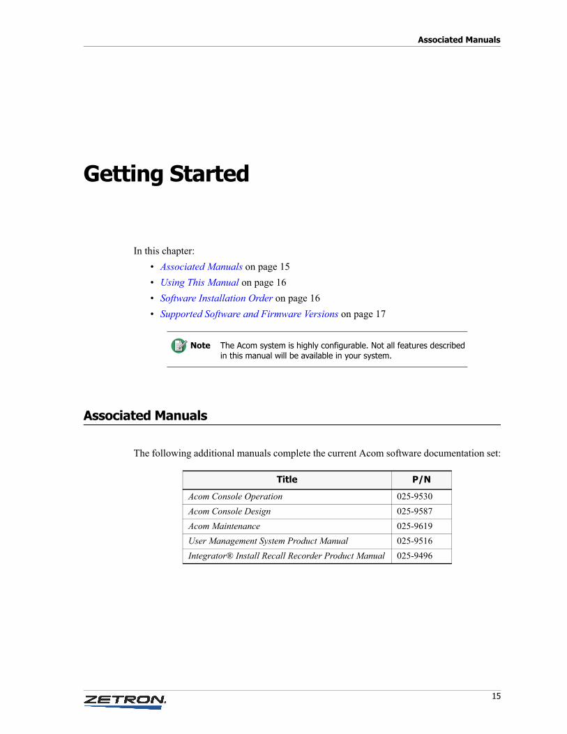
Associated Manuals
The following additional manuals complete the current Acom software documentation set:
Note The Acom system is highly configurable. Not all features described in this manual will be available in your system.
Title P/N
Acom Console Operation 025-9530
Acom Console Design 025-9587
Acom Maintenance 025-9619
User Management System Product Manual 025-9516
Integrator® Install Recall Recorder Product Manual 025-9496
Getting Started
16 025-9529P
Using This Manual
This manual covers configuration of Acom and related Zetron software. It is designed for personnel who are responsible for installing the software and configuring the Acom system.
The Integrated Management System (IMS) is a suite of applications for configuring all of the primary hardware components. IMS is divided into four software modules, which are presented in this manual in the following order:
• IMS ALS — for configuring Acom Line Subracks (ALSes). Acom supports up to 2,200 lines.
• IMS ADS — for configuring Acom DS3 Subracks (ADSes).
• IMS ACU — for configuring Acom Console Units (ACUs), which interface and control the behavior of the call-taking consoles. Acom supports up to 200 consoles.
• IMS Terminal — for graphically accessing and managing ALSes, ADSes, and ACUs.
The manual also covers the suite of console configuration utilities.
Software Installation Order
The remaining chapters of this manual describe Acom software configuration tasks in the order in which they are typically performed. Refer to the appropriate chapter as you reach that point in the installation/configuration process.
• Configuring Acom Line Subracks with the IMS ALS Module on page 19
• Configuring Acom DS3 Subracks with the IMS ADS Module on page 173
• Configuring Acom Console Units with the IMS ACU Module on page 225
• Managing Network Devices with the IMS Terminal Module on page 279
• Console Applications and Administrative Tools on page 295
Caution! There are two prerequisite programs for some of Zetron’s software: Microsoft .NET Framework (.NET) and Borland Database Engine (BDE). They are provided on the Acom CD and need to be installed before the rest of the software.
After installing BDE, see Installing IMS Terminal on page 279. There is a setting in BDE that you must change from its default before you install IMS Terminal. Otherwise you will get the BLOB error mentioned there and have to reinstall everything!
!
17
Supported Software and Firmware Versions
• Appendix A: Acom Console Software Configuration File (AcomConsole.ini) on page 327
• Appendix B: Voter Serial Interface on page 377
• Appendix C: Distributing Console Files on page 389
• Appendix D: OpenSky Configuration on page 409
• Appendix E: SNMP on page 421
• Appendix F: Intersite Bearers on page 427
• Appendix G: Acom Glossary on page 437
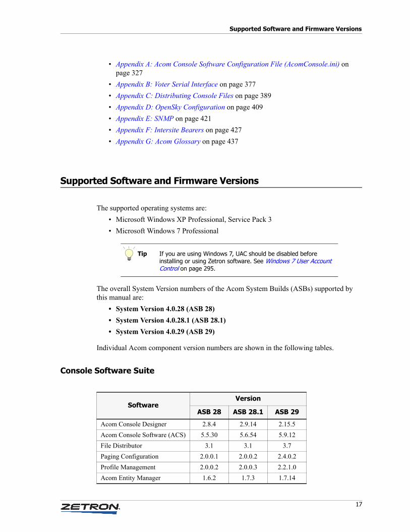
Supported Software and Firmware Versions
The supported operating systems are:
• Microsoft Windows XP Professional, Service Pack 3
• Microsoft Windows 7 Professional
The overall System Version numbers of the Acom System Builds (ASBs) supported by this manual are:
• System Version 4.0.28 (ASB 28)
• System Version 4.0.28.1 (ASB 28.1)
• System Version 4.0.29 (ASB 29)
Individual Acom component version numbers are shown in the following tables.
Console Software Suite
Tip If you are using Windows 7, UAC should be disabled before installing or using Zetron software. See Windows 7 User Account Control on page 295.
SoftwareVersion
ASB 28 ASB 28.1 ASB 29
Acom Console Designer 2.8.4 2.9.14 2.15.5
Acom Console Software (ACS) 5.5.30 5.6.54 5.9.12
File Distributor 3.1 3.1 3.7
Paging Configuration 2.0.0.1 2.0.0.2 2.4.0.2
Profile Management 2.0.0.2 2.0.0.3 2.2.1.0
Acom Entity Manager 1.6.2 1.7.3 1.7.14
Getting Started
18 025-9529P
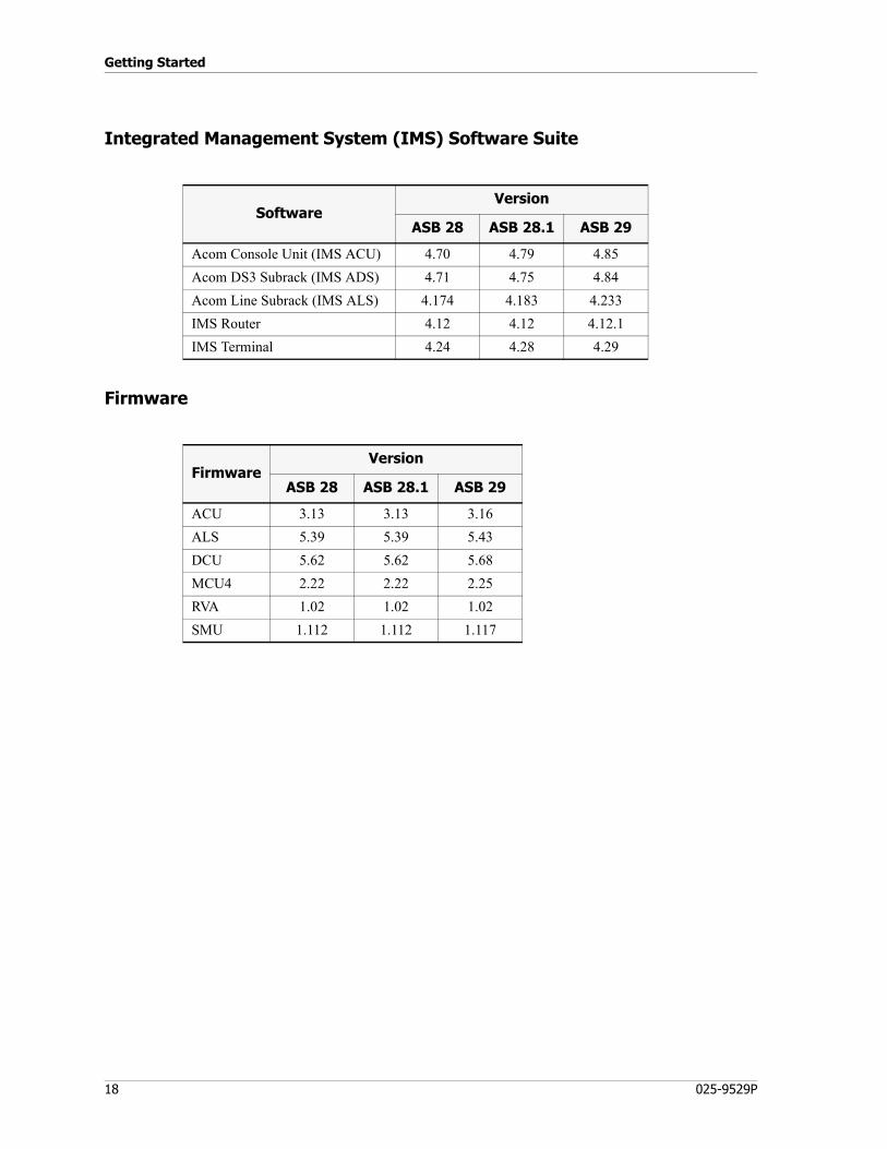
Integrated Management System (IMS) Software Suite
Firmware
SoftwareVersion
ASB 28 ASB 28.1 ASB 29
Acom Console Unit (IMS ACU) 4.70 4.79 4.85
Acom DS3 Subrack (IMS ADS) 4.71 4.75 4.84
Acom Line Subrack (IMS ALS) 4.174 4.183 4.233
IMS Router 4.12 4.12 4.12.1
IMS Terminal 4.24 4.28 4.29
FirmwareVersion
ASB 28 ASB 28.1 ASB 29
ACU 3.13 3.13 3.16
ALS 5.39 5.39 5.43
DCU 5.62 5.62 5.68
MCU4 2.22 2.22 2.25
RVA 1.02 1.02 1.02
SMU 1.112 1.112 1.117
19
Configuring Acom Line Subracks with the IMS ALS Module
This chapter describes the ALS module of the Integrated Management System (IMS), software designed for configuring and managing standalone or networked Line Subracks (ALSes) that are part of an Acom system.
In this chapter:
• Getting Started on page 20
• Managing Configurations (File Menu) on page 25
• Communicating with the Subrack (Communication Menu) on page 28
• Configuring ALS Parameters (Configure Menu) on page 32
• Alarm Menu on page 78
• Tools Menu on page 83
• MCU3/4 Card Options on page 88
• MSU3 Card Options on page 123
• EMU Card Options on page 128
• SMU Card Options on page 137
• UIO Card Options on page 144
• DIU1-4 and DIU1-2 Card Options on page 147
• RIU Card Options on page 151
• RVA Card Options on page 157
• EIE Card Options on page 160
• TIE Card Options on page 167
Configuring Acom Line Subracks with the IMS ALS Module
20 025-9529P
Getting Started
Supported Cards
The IMS ALS application is capable of configuring numerous types of interface cards. This chapter describes only the “core” cards, which are as follows:
• MCU3 or MCU4 (Main Control Unit) — The primary voice and data switching card in the system.
The MCU3/4 is a switch equipped with dual T1/E1/ISDN interfaces (electrical or optical) that are used to connect with digital phone lines, other MCU3/4s in the system, and operator consoles. Each subrack contains one or more MCU3/4s. When installed in slot 0, it also acts as the Main Controller for the rack. For more information, see MCU3/4 Card Options on page 88.
• MSU3 (Main Supply Unit) — Provides DC-DC conversion to power a subrack from an external voltage source, converting –48V to +5V and ±12V. Each subrack typically has just one MSU3, but a second can be added to provide redundant power supplies at the subrack level. For more information, see MSU3 Card Options on page 123.
• EMU (Ear and Mouth (E&M) Unit) — Provides six E&M 4-wire interfaces to connect the Acom switch to external communication equipment such as radios, operator audio equipment, voice loggers, and 4-wire PABX lines. Tone remote control of radios is also provided by the EMU. For more information, see EMU Card Options on page 128.
• SMU (Signaling Management Unit) — Provides a variety of tone signaling and digital audio capabilities such as DTMF, tone remote control, voice-detect (VOX), paging, Selcal, 5/6 tone generation, specialized custom tone generation and detection, VoIP, and caller ID. For more information, see SMU Card Options on page 137.
• UIO (Universal Input/Output) — Provides connections from the channel interfaces to the primary MCU3/4 by way of the backplane data bus. Provides an interface between the Acom system and external equipment requiring discrete contact closure signals. Each ALS may contain up to 10 UIO cards, for a maximum of 160 digital inputs and 160 digital outputs. An Acom system as a whole will support up to 228 digital inputs and 228 digital outputs. For more information, see UIO Card Options on page 144.
• DIU1-4 (Data Interface Unit) — Provides a serial data connection between external data equipment and the Acom system. When DIU1-4 cards are placed at multiple sites across a network and connected by way of T1 or E1 links, transparent connections can be established that allow the various pieces of equipment to communicate with each other (that is, Zetron or third party data equipment can be
Note Since an ALS can take either an MCU3-class or an MCU4-class card, they are referred to collectively in this chapter as MCU3/4 cards.
21
Getting Started
multiplexed through the Acom system). For more information, see DIU1-4 and DIU1-2 Card Options on page 147.
• RIU (Radio Interface Unit) — Provides a generic connection to up to six local radios. For more information, see RIU Card Options on page 151.
• RVA (Recorded Voice Announcement) — Provides configuration of up to 32 recorded voice announcements, each capable of 15 separate sequences of events. For more information, see RVA Card Options on page 157.
• EIE (Exchange Interface Equipment) — Provides six lines for telephone system access. The EIE card provides 2-wire interfaces to connect the Acom switch to a Private Automatic Branch Exchange (PABX) or Public Switched Telephone Network (PSTN) and handles all ring detection and telephone line state detection. For more information, see EIE Card Options on page 160.
• TIE (Telephone Interface Equipment) — Provides six circuits for ringdown (direct connect) telephone lines. The TIE card provides 2-wire interfaces to connect the Acom switch to analog handsets for dedicated connections between operators and local or remote, direct-connect phones. A Ring Generator Unit provides the ring voltage for the subscriber handsets. For more information, see TIE Card Options on page 167.
Using IMS ALS with or without IMS Terminal
IMS ALS may be operated in conjunction with IMS Terminal or as an independent module. If it is used with IMS Terminal, you must copy the IMS_ALS.EXE file into the IMS Terminal folder and register IMS ALS with IMS Terminal. To register, run IMS Terminal Config, check the box labeled ACOMIII, and click OK.
For more information, see Managing Network Devices with the IMS Terminal Module on page 279.
Configuring Acom Line Subracks with the IMS ALS Module
22 025-9529P
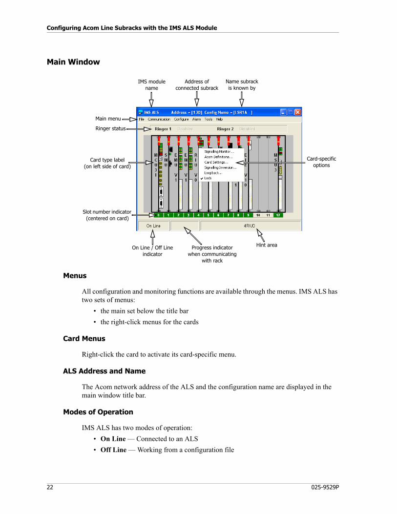
Main Window
Menus
All configuration and monitoring functions are available through the menus. IMS ALS has two sets of menus:
• the main set below the title bar
• the right-click menus for the cards
Card Menus
Right-click the card to activate its card-specific menu.
ALS Address and Name
The Acom network address of the ALS and the configuration name are displayed in the main window title bar.
Modes of Operation
IMS ALS has two modes of operation:
• On Line — Connected to an ALS
• Off Line — Working from a configuration file
IMS modulename
Address ofconnected subrack
Name subrackis known by
Card-specificoptions
On Line / Off Lineindicator
Progress indicatorwhen communicating
with rack
Hint area
Ringer status
Card type label(on left side of card)
Slot number indicator (centered on card)
Main menu
23
Getting Started
The operating mode is displayed in the lower left corner of the main window. When offline, certain menu items are not available. Unavailable menu items are grayed out.
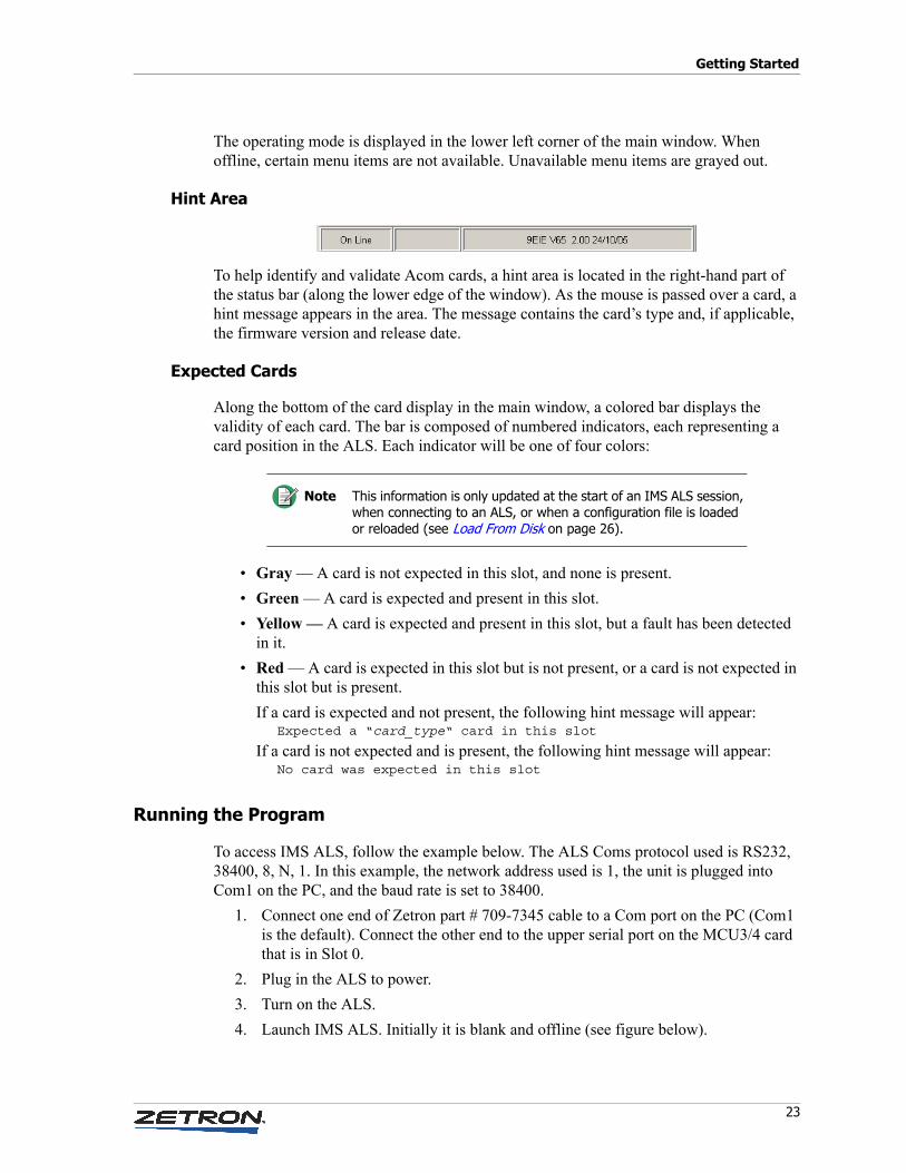
Hint Area
To help identify and validate Acom cards, a hint area is located in the right-hand part of the status bar (along the lower edge of the window). As the mouse is passed over a card, a hint message appears in the area. The message contains the card’s type and, if applicable, the firmware version and release date.
Expected Cards
Along the bottom of the card display in the main window, a colored bar displays the validity of each card. The bar is composed of numbered indicators, each representing a card position in the ALS. Each indicator will be one of four colors:
• Gray — A card is not expected in this slot, and none is present.
• Green — A card is expected and present in this slot.
• Yellow — A card is expected and present in this slot, but a fault has been detected in it.
• Red — A card is expected in this slot but is not present, or a card is not expected in this slot but is present.
If a card is expected and not present, the following hint message will appear:Expected a “card_type“ card in this slot
If a card is not expected and is present, the following hint message will appear:No card was expected in this slot
Running the Program
To access IMS ALS, follow the example below. The ALS Coms protocol used is RS232, 38400, 8, N, 1. In this example, the network address used is 1, the unit is plugged into Com1 on the PC, and the baud rate is set to 38400.
1. Connect one end of Zetron part # 709-7345 cable to a Com port on the PC (Com1 is the default). Connect the other end to the upper serial port on the MCU3/4 card that is in Slot 0.
2. Plug in the ALS to power.
3. Turn on the ALS.
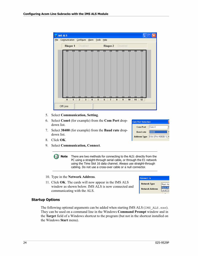
4. Launch IMS ALS. Initially it is blank and offline (see figure below).
Note This information is only updated at the start of an IMS ALS session, when connecting to an ALS, or when a configuration file is loaded or reloaded (see Load From Disk on page 26).
Configuring Acom Line Subracks with the IMS ALS Module
24 025-9529P
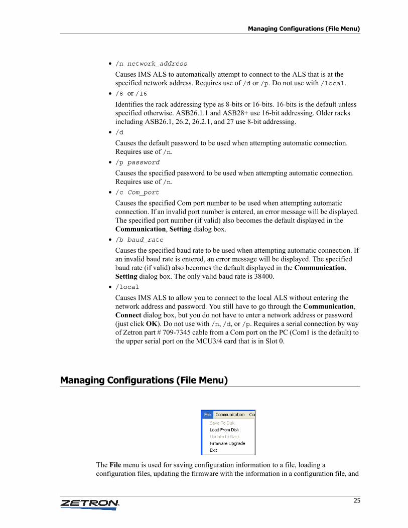
5. Select Communication, Setting.
6. Select Com4 (for example) from the Com Port drop-down list.
7. Select 38400 (for example) from the Baud rate drop-down list.
8. Click OK.
9. Select Communication, Connect.
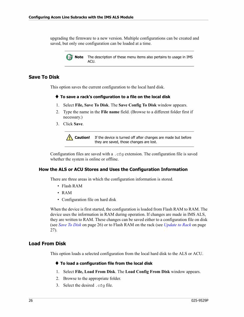
10. Type in the Network Address.
11. Click OK. The cards will now appear in the IMS ALS window as shown below. IMS ALS is now connected and communicating with the ALS.
Startup Options
The following optional arguments can be added when starting IMS ALS (IMS_ALS.exe). They can be used on a command line in the Windows Command Prompt window and in the Target field of a Windows shortcut to the program (but not in the shortcut installed on the Windows Start menu).
Note There are two methods for connecting to the ALS: directly from the PC using a straight-through serial cable, or through the E1 network using the Time Slot 16 data channel. Always use straight-through cabling. Do not use a cross-over cable or a null connector.
25
Managing Configurations (File Menu)
• /n network_address
Causes IMS ALS to automatically attempt to connect to the ALS that is at the specified network address. Requires use of /d or /p. Do not use with /local.
• /8 or /16
Identifies the rack addressing type as 8-bits or 16-bits. 16-bits is the default unless specified otherwise. ASB26.1.1 and ASB28+ use 16-bit addressing. Older racks including ASB26.1, 26.2, 26.2.1, and 27 use 8-bit addressing.
• /d
Causes the default password to be used when attempting automatic connection. Requires use of /n.
• /p password
Causes the specified password to be used when attempting automatic connection. Requires use of /n.
• /c Com_port
Causes the specified Com port number to be used when attempting automatic connection. If an invalid port number is entered, an error message will be displayed. The specified port number (if valid) also becomes the default displayed in the Communication, Setting dialog box.
• /b baud_rate
Causes the specified baud rate to be used when attempting automatic connection. If an invalid baud rate is entered, an error message will be displayed. The specified baud rate (if valid) also becomes the default displayed in the Communication, Setting dialog box. The only valid baud rate is 38400.
• /local
Causes IMS ALS to allow you to connect to the local ALS without entering the network address and password. You still have to go through the Communication, Connect dialog box, but you do not have to enter a network address or password (just click OK). Do not use with /n, /d, or /p. Requires a serial connection by way of Zetron part # 709-7345 cable from a Com port on the PC (Com1 is the default) to the upper serial port on the MCU3/4 card that is in Slot 0.
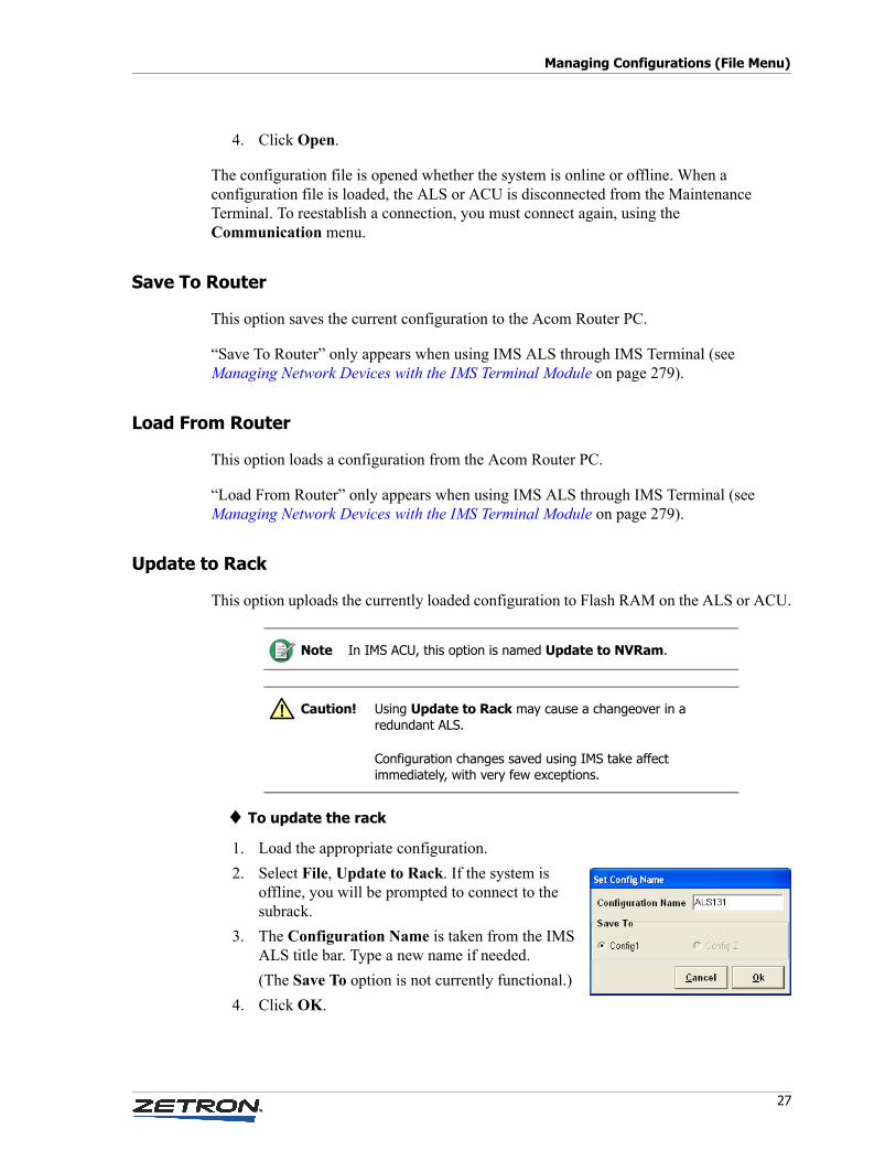
Managing Configurations (File Menu)
The File menu is used for saving configuration information to a file, loading a configuration files, updating the firmware with the information in a configuration file, and
Configuring Acom Line Subracks with the IMS ALS Module
26 025-9529P
upgrading the firmware to a new version. Multiple configurations can be created and saved, but only one configuration can be loaded at a time.
Save To Disk
This option saves the current configuration to the local hard disk.
♦ To save a rack’s configuration to a file on the local disk
1. Select File, Save To Disk. The Save Config To Disk window appears.
2. Type the name in the File name field. (Browse to a different folder first if necessary.)
3. Click Save.
Configuration files are saved with a .cfg extension. The configuration file is saved whether the system is online or offline.
How the ALS or ACU Stores and Uses the Configuration Information
There are three areas in which the configuration information is stored.
• Flash RAM
• RAM
• Configuration file on hard disk
When the device is first started, the configuration is loaded from Flash RAM to RAM. The device uses the information in RAM during operation. If changes are made in IMS ALS, they are written to RAM. These changes can be saved either to a configuration file on disk (see Save To Disk on page 26) or to Flash RAM on the rack (see Update to Rack on page 27).
Load From Disk
This option loads a selected configuration from the local hard disk to the ALS or ACU.
♦ To load a configuration file from the local disk
1. Select File, Load From Disk. The Load Config From Disk window appears.
2. Browse to the appropriate folder.
3. Select the desired .cfg file.
Note The description of these menu items also pertains to usage in IMS ACU.
Caution! If the device is turned off after changes are made but before they are saved, those changes are lost.
!
27
Managing Configurations (File Menu)
4. Click Open.
The configuration file is opened whether the system is online or offline. When a configuration file is loaded, the ALS or ACU is disconnected from the Maintenance Terminal. To reestablish a connection, you must connect again, using the Communication menu.
Save To Router
This option saves the current configuration to the Acom Router PC.
“Save To Router” only appears when using IMS ALS through IMS Terminal (see Managing Network Devices with the IMS Terminal Module on page 279).
Load From Router
This option loads a configuration from the Acom Router PC.
“Load From Router” only appears when using IMS ALS through IMS Terminal (see Managing Network Devices with the IMS Terminal Module on page 279).
Update to Rack
This option uploads the currently loaded configuration to Flash RAM on the ALS or ACU.
♦ To update the rack
1. Load the appropriate configuration.
2. Select File, Update to Rack. If the system is offline, you will be prompted to connect to the subrack.
3. The Configuration Name is taken from the IMS ALS title bar. Type a new name if needed.
(The Save To option is not currently functional.)
4. Click OK.
Note In IMS ACU, this option is named Update to NVRam.
Caution! Using Update to Rack may cause a changeover in a redundant ALS.
Configuration changes saved using IMS take affect immediately, with very few exceptions.
!
Configuring Acom Line Subracks with the IMS ALS Module
28 025-9529P
Firmware Upgrade
This option is not currently functional. Refer to Acom Maintenance (P/N 025-9619) for complete information on firmware upgrades.
Exit
When you select this option, the IMS ALS application closes.
Communicating with the Subrack (Communication Menu)
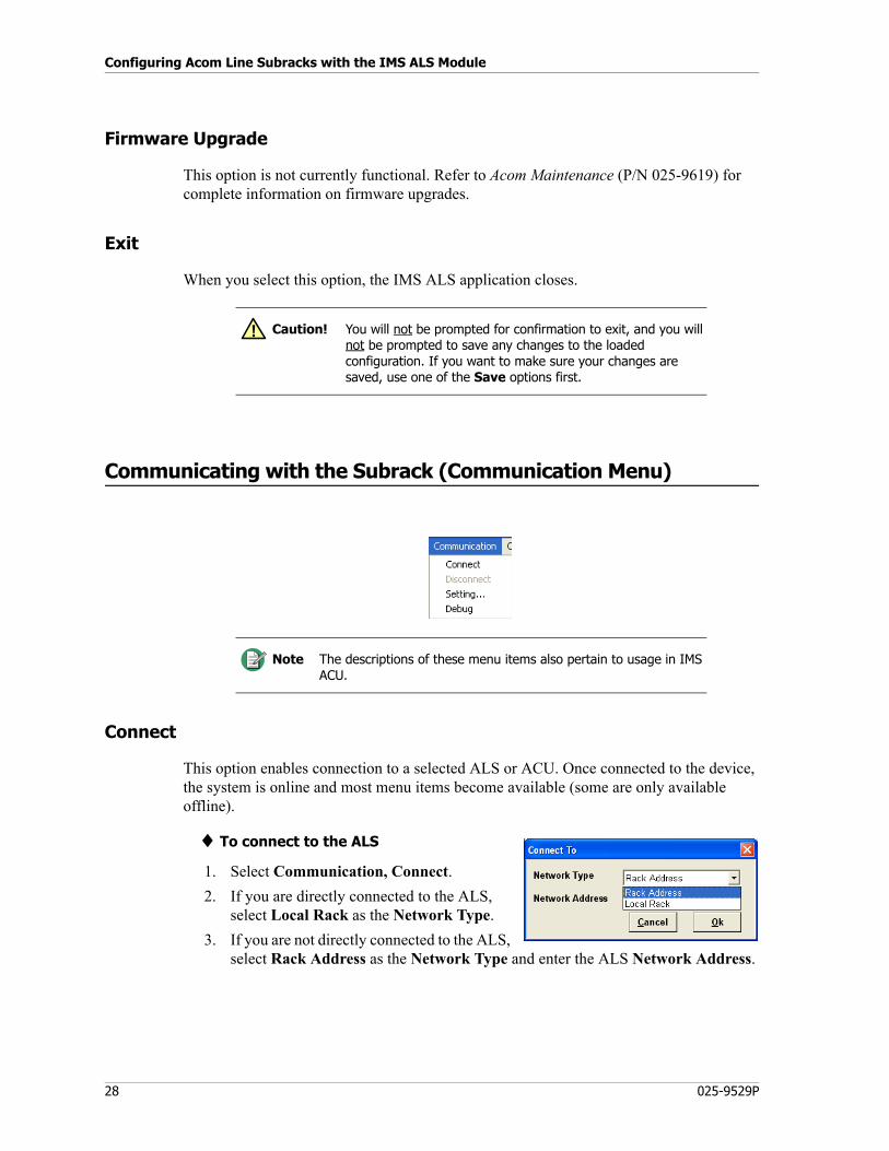
Connect
This option enables connection to a selected ALS or ACU. Once connected to the device, the system is online and most menu items become available (some are only available offline).
♦ To connect to the ALS
1. Select Communication, Connect.
2. If you are directly connected to the ALS, select Local Rack as the Network Type.
3. If you are not directly connected to the ALS, select Rack Address as the Network Type and enter the ALS Network Address.
Caution! You will not be prompted for confirmation to exit, and you will not be prompted to save any changes to the loaded configuration. If you want to make sure your changes are saved, use one of the Save options first.
!
Note The descriptions of these menu items also pertain to usage in IMS ACU.
29
Communicating with the Subrack (Communication Menu)
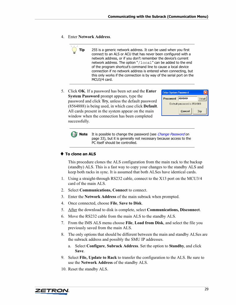
4. Enter Network Address.
5. Click OK. If a password has been set and the Enter System Password prompt appears, type the password and click Try, unless the default password (8564888) is being used, in which case click Default. All cards present in the system appear on the main window when the connection has been completed successfully.
♦ To clone an ALS
This procedure clones the ALS configuration from the main rack to the backup (standby) ALS. This is a fast way to copy your changes to the standby ALS and keep both racks in sync. It is assumed that both ALSes have identical cards.
1. Using a straight-through RS232 cable, connect to the X13 port on the MCU3/4 card of the main ALS.
2. Select Communications, Connect to connect.
3. Enter the Network Address of the main subrack when prompted.
4. Once connected, choose File, Save to Disk.
5. After the download to disk is complete, select Communications, Disconnect.
6. Move the RS232 cable from the main ALS to the standby ALS.
7. From the IMS ALS menu choose File, Load from Disk, and select the file you previously saved from the main ALS.
8. The only options that should be different between the main and standby ALSes are the subrack address and possibly the SMU IP addresses.
a. Select Configure, Subrack Address. Set the option to Standby, and click Save.
9. Select File, Update to Rack to transfer the configuration to the ALS. Be sure to use the Network Address of the standby ALS.
10. Reset the standby ALS.
Tip 255 is a generic network address. It can be used when you first connect to an ALS or ACU that has never been configured with a network address, or if you don’t remember the device’s current network address. The option “/local” can be added to the end of the program shortcut’s command line to cause a local device connection if no network address is entered when connecting, but this only works if the connection is by way of the serial port on the MCU3/4 card.
Note It is possible to change the password (see Change Password on page 33), but it is generally not necessary because access to the PC itself should be controlled.
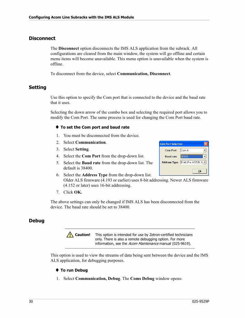
Configuring Acom Line Subracks with the IMS ALS Module
30 025-9529P
Disconnect
The Disconnect option disconnects the IMS ALS application from the subrack. All configurations are cleared from the main window, the system will go offline and certain menu items will become unavailable. This menu option is unavailable when the system is offline.
To disconnect from the device, select Communication, Disconnect.
Setting
Use this option to specify the Com port that is connected to the device and the baud rate that it uses.
Selecting the down arrow of the combo box and selecting the required port allows you to modify the Com Port. The same process is used for changing the Com Port baud rate.
♦ To set the Com port and baud rate
1. You must be disconnected from the device.
2. Select Communication.
3. Select Setting.
4. Select the Com Port from the drop-down list.
5. Select the Baud rate from the drop-down list. The default is 38400.
6. Select the Address Type from the drop-down list. Older ALS firmware (4.193 or earlier) uses 8-bit addressing. Newer ALS firmware (4.152 or later) uses 16-bit addressing.
7. Click OK.
The above settings can only be changed if IMS ALS has been disconnected from the device. The baud rate should be set to 38400.
Debug
This option is used to view the streams of data being sent between the device and the IMS ALS application, for debugging purposes.
♦ To run Debug
1. Select Communication, Debug. The Coms Debug window opens:
Caution! This option is intended for use by Zetron-certified technicians only. There is also a remote debugging option. For more information, see the Acom Maintenance manual (025-9619).
!
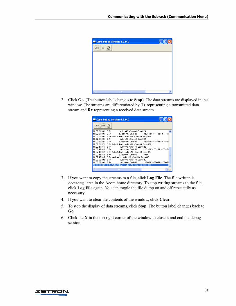
31
Communicating with the Subrack (Communication Menu)
2. Click Go. (The button label changes to Stop). The data streams are displayed in the window. The streams are differentiated by Tx representing a transmitted data stream and Rx representing a received data stream.
3. If you want to copy the streams to a file, click Log File. The file written is comsdbg.txt in the Acom home directory. To stop writing streams to the file, click Log File again. You can toggle the file dump on and off repeatedly as necessary.
4. If you want to clear the contents of the window, click Clear.
5. To stop the display of data streams, click Stop. The button label changes back to Go.
6. Click the X in the top right corner of the window to close it and end the debug session.
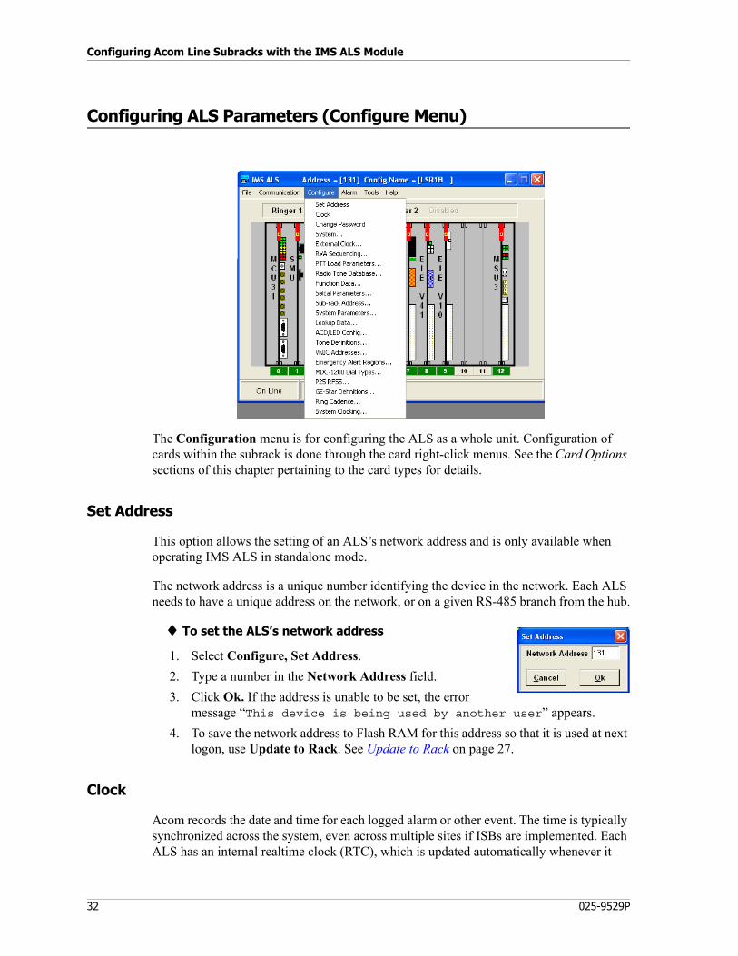
Configuring Acom Line Subracks with the IMS ALS Module
32 025-9529P
Configuring ALS Parameters (Configure Menu)
The Configuration menu is for configuring the ALS as a whole unit. Configuration of cards within the subrack is done through the card right-click menus. See the Card Options sections of this chapter pertaining to the card types for details.
Set Address
This option allows the setting of an ALS’s network address and is only available when operating IMS ALS in standalone mode.
The network address is a unique number identifying the device in the network. Each ALS needs to have a unique address on the network, or on a given RS-485 branch from the hub.
♦ To set the ALS’s network address
1. Select Configure, Set Address.
2. Type a number in the Network Address field.
3. Click Ok. If the address is unable to be set, the error message “This device is being used by another user” appears.
4. To save the network address to Flash RAM for this address so that it is used at next logon, use Update to Rack. See Update to Rack on page 27.
Clock
Acom records the date and time for each logged alarm or other event. The time is typically synchronized across the system, even across multiple sites if ISBs are implemented. Each ALS has an internal realtime clock (RTC), which is updated automatically whenever it
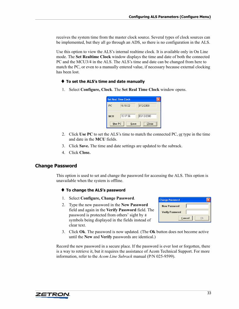
33
Configuring ALS Parameters (Configure Menu)
receives the system time from the master clock source. Several types of clock sources can be implemented, but they all go through an ADS, so there is no configuration in the ALS.
Use this option to view the ALS’s internal realtime clock. It is available only in On Line mode. The Set Realtime Clock window displays the time and date of both the connected PC and the MCU3/4 in the ALS. The ALS’s time and date can be changed from here to match the PC, or even to a manually entered value, if necessary because external clocking has been lost.
♦ To set the ALS’s time and date manually
1. Select Configure, Clock. The Set Real Time Clock window opens.
2. Click Use PC to set the ALS’s time to match the connected PC, or type in the time and date in the MCU fields.
3. Click Save. The time and date settings are updated to the subrack.
4. Click Close.
Change Password
This option is used to set and change the password for accessing the ALS. This option is unavailable when the system is offline.
♦ To change the ALS’s password
1. Select Configure, Change Password.
2. Type the new password in the New Password field and again in the Verify Password field. The password is protected from others’ sight by # symbols being displayed in the fields instead of clear text.
3. Click Ok. The password is now updated. (The Ok button does not become active until the New and Verify passwords are identical.)
Record the new password in a secure place. If the password is ever lost or forgotten, there is a way to retrieve it, but it requires the assistance of Acom Technical Support. For more information, refer to the Acom Line Subrack manual (P/N 025-9599).
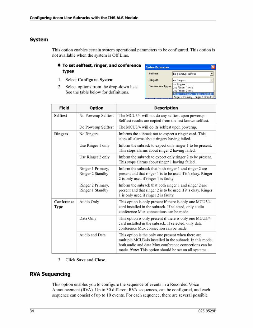
Configuring Acom Line Subracks with the IMS ALS Module
34 025-9529P
System
This option enables certain system operational parameters to be configured. This option is not available when the system is Off Line.
♦ To set selftest, ringer, and conference types
1. Select Configure, System.
2. Select options from the drop-down lists. See the table below for definitions.
3. Click Save and Close.
RVA Sequencing
This option enables you to configure the sequence of events in a Recorded Voice Announcement (RVA). Up to 30 different RVA sequences, can be configured, and each sequence can consist of up to 10 events. For each sequence, there are several possible
Field Option Description
Selftest No Powerup Selftest The MCU3/4 will not do any selftest upon powerup. Selftest results are copied from the last known selftest.
Do Powerup Selftest The MCU3/4 will do its selftest upon powerup.
Ringers No Ringers Informs the subrack not to expect a ringer card. This stops all alarms about ringers having failed.
Use Ringer 1 only Inform the subrack to expect only ringer 1 to be present. This stops alarms about ringer 2 having failed.
Use Ringer 2 only Inform the subrack to expect only ringer 2 to be present. This stops alarms about ringer 1 having failed.
Ringer 1 Primary,Ringer 2 Standby
Inform the subrack that both ringer 1 and ringer 2 are present and that ringer 1 is to be used if it’s okay. Ringer 2 is only used if ringer 1 is faulty.
Ringer 2 Primary,Ringer 1 Standby
Inform the subrack that both ringer 1 and ringer 2 are present and that ringer 2 is to be used if it’s okay. Ringer 1 is only used if ringer 2 is faulty.
ConferenceType
Audio Only This option is only present if there is only one MCU3/4 card installed in the subrack. If selected, only audio conference Mux connections can be made.
Data Only This option is only present if there is only one MCU3/4 card installed in the subrack. If selected, only data conference Mux connection can be made.
Audio and Data This option is the only one present when there are multiple MCU3/4s installed in the subrack. In this mode, both audio and data Mux conference connections can be made. Note: This option should be set on all systems.
35
Configuring ALS Parameters (Configure Menu)
commands, including playing recorded messages from the RVA card, plus other options, which allows for considerable flexibility of recorded announcements.
RVA sequencing is typically used in conjunction with Automatic Call Distribution (ACD). A non-ACD line can be configured to begin an RVA sequence automatically with an incoming call. Set the RVA Seq ID in the Acom Definitions Miscellaneous tab (see Miscellaneous Tab on page 100).
For example, when a call is received, it triggers the playing of a certain RVA sequence (such as an announcement that an operator will be with the caller shortly). But RVA sequencing is not limited to ACD. It can be used to complement other tasks in the ALS, such as autoconnect.
RVA sequencing is not dependent on having an RVA card in the ALS, although it is most effective in conjunction with an RVA card, being able to play customizable announcements. The only command not available without an RVA card is Play RVA Message.
Interactive Voice Response (IVR)
For information on applying RVA sequences to enhance ACD, see ACD/LED Config on page 54.
This feature requires the Autocall feature. See To set up a line to use the Autocall feature, as required by IVR and Auto Answer on page 112.
The purpose of this feature is to give a caller in the ACD queue the option of leaving a message rather than remaining in the queue. Queues can be configured to play a message prompting the caller to press a key to leave a voice message. The system will expect a DTMF response from the caller, which will be used to direct the call to the PABX voice mail system.
When a caller presses a key during an RVA sequence configured for IVR, and if the key pressed matches the configuration, the RVA sequence will be paused and an Autocall placed to the voice mailbox. If the Autocall to the voice mailbox cannot be established, the RVA sequence will continue. If it is established successfully, the call is removed from the ACD queue.
The RVA Sequence shown in the following figure would be used for an incoming call on a line whose RVA Seq ID is set to 4. This is done by way of the ACD/LED Config option on the Configuration menu. See Queue Configuration Tab on page 56.
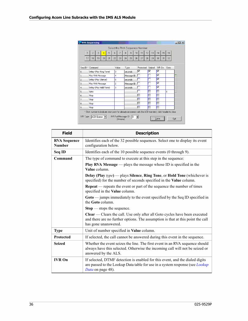
Configuring Acom Line Subracks with the IMS ALS Module
36 025-9529P
Field Description
RVA SequenceNumber
Identifies each of the 32 possible sequences. Select one to display its event configuration below.
Seq ID Identifies each of the 10 possible sequence events (0 through 9).
Command The type of command to execute at this step in the sequence:
Play RVA Message — plays the message whose ID is specified in the Value column.
Delay (Play type) — plays Silence, Ring Tone, or Hold Tone (whichever is specified) for the number of seconds specified in the Value column.
Repeat — repeats the event or part of the sequence the number of times specified in the Value column.
Goto — jumps immediately to the event specified by the Seq ID specified in the Goto column.
Stop — stops the sequence.
Clear — Clears the call. Use only after all Goto cycles have been executed and there are no further options. The assumption is that at this point the call has gone unanswered.
Type Unit of number specified in Value column.
Protected If selected, the call cannot be answered during this event in the sequence.
Seized Whether the event seizes the line. The first event in an RVA sequence should always have this selected. Otherwise the incoming call will not be seized or answered by the ALS.
IVR On If selected, DTMF detection is enabled for this event, and the dialed digits are passed to the Lookup Data table for use in a system response (see Lookup Data on page 48).
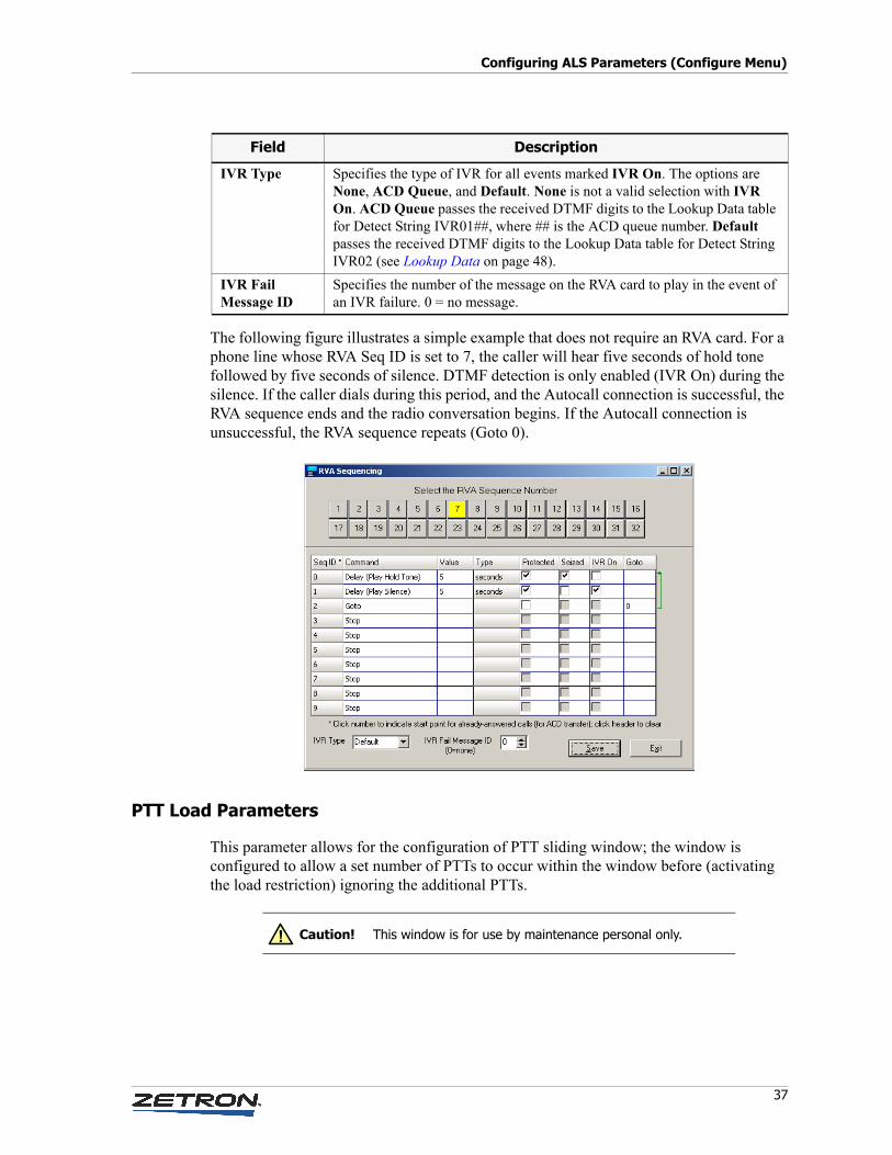
37
Configuring ALS Parameters (Configure Menu)
The following figure illustrates a simple example that does not require an RVA card. For a phone line whose RVA Seq ID is set to 7, the caller will hear five seconds of hold tone followed by five seconds of silence. DTMF detection is only enabled (IVR On) during the silence. If the caller dials during this period, and the Autocall connection is successful, the RVA sequence ends and the radio conversation begins. If the Autocall connection is unsuccessful, the RVA sequence repeats (Goto 0).
PTT Load Parameters
This parameter allows for the configuration of PTT sliding window; the window is configured to allow a set number of PTTs to occur within the window before (activating the load restriction) ignoring the additional PTTs.
IVR Type Specifies the type of IVR for all events marked IVR On. The options are None, ACD Queue, and Default. None is not a valid selection with IVR On. ACD Queue passes the received DTMF digits to the Lookup Data table for Detect String IVR01##, where ## is the ACD queue number. Default passes the received DTMF digits to the Lookup Data table for Detect String IVR02 (see Lookup Data on page 48).
IVR FailMessage ID
Specifies the number of the message on the RVA card to play in the event of an IVR failure. 0 = no message.
Field Description
Caution! This window is for use by maintenance personal only.!
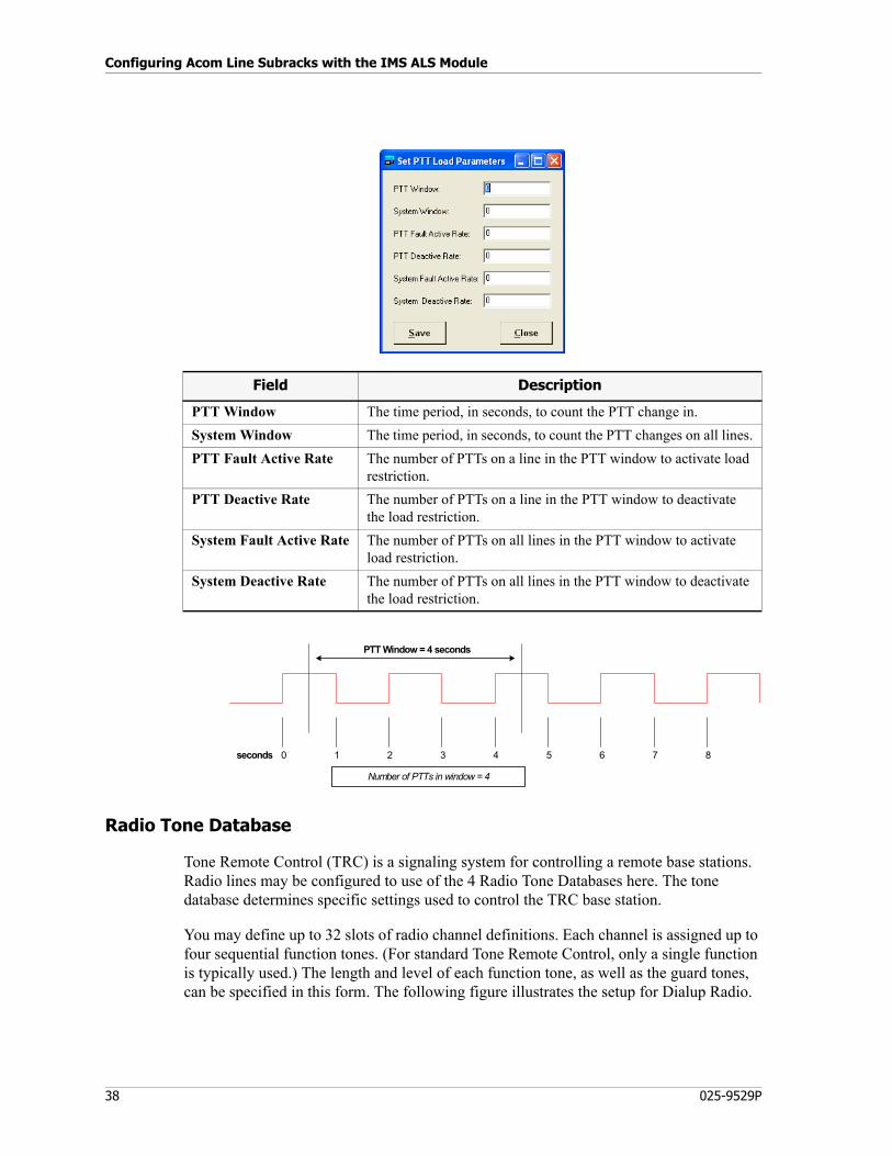
Configuring Acom Line Subracks with the IMS ALS Module
38 025-9529P
Radio Tone Database
Tone Remote Control (TRC) is a signaling system for controlling a remote base stations. Radio lines may be configured to use of the 4 Radio Tone Databases here. The tone database determines specific settings used to control the TRC base station.
You may define up to 32 slots of radio channel definitions. Each channel is assigned up to four sequential function tones. (For standard Tone Remote Control, only a single function is typically used.) The length and level of each function tone, as well as the guard tones, can be specified in this form. The following figure illustrates the setup for Dialup Radio.
Field Description
PTT Window The time period, in seconds, to count the PTT change in.
System Window The time period, in seconds, to count the PTT changes on all lines.
PTT Fault Active Rate The number of PTTs on a line in the PTT window to activate load restriction.
PTT Deactive Rate The number of PTTs on a line in the PTT window to deactivate the load restriction.
System Fault Active Rate The number of PTTs on all lines in the PTT window to activate load restriction.
System Deactive Rate The number of PTTs on all lines in the PTT window to deactivate the load restriction.
0 2 4 6 81 3 5 7
PTT Window = 4 seconds
Number of PTTs in window = 4
seconds
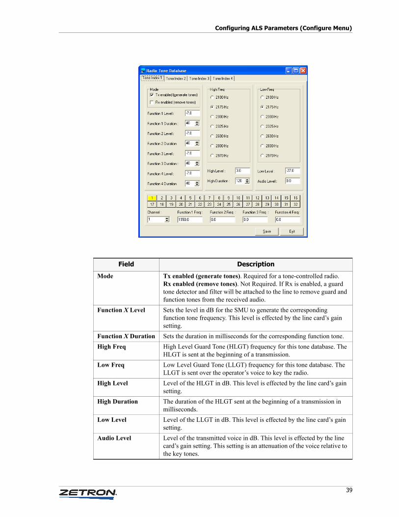
39
Configuring ALS Parameters (Configure Menu)
Field Description
Mode Tx enabled (generate tones). Required for a tone-controlled radio.Rx enabled (remove tones). Not Required. If Rx is enabled, a guard tone detector and filter will be attached to the line to remove guard and function tones from the received audio.
Function X Level Sets the level in dB for the SMU to generate the corresponding function tone frequency. This level is effected by the line card’s gain setting.
Function X Duration Sets the duration in milliseconds for the corresponding function tone.
High Freq High Level Guard Tone (HLGT) frequency for this tone database. The HLGT is sent at the beginning of a transmission.
Low Freq Low Level Guard Tone (LLGT) frequency for this tone database. The LLGT is sent over the operator’s voice to key the radio.
High Level Level of the HLGT in dB. This level is effected by the line card’s gain setting.
High Duration The duration of the HLGT sent at the beginning of a transmission in milliseconds.
Low Level Level of the LLGT in dB. This level is effected by the line card’s gain setting.
Audio Level Level of the transmitted voice in dB. This level is effected by the line card’s gain setting. This setting is an attenuation of the voice relative to the key tones.
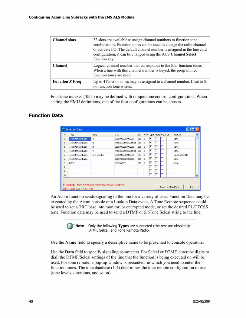
Configuring Acom Line Subracks with the IMS ALS Module
40 025-9529P
Four tone indexes (Tabs) may be defined with unique tone control configurations. When setting the EMU definitions, one of the four configurations can be chosen.
Function Data
An Acom function sends signaling to the line for a variety of uses. Function Data may be executed by the Acom console or a Lookup Data event, A Tone Remote sequence could be used to set a TRC base into monitor, or encrypted mode, or set the desired PL/CTCSS tone. Function data may be used to send a DTMF or 5/6Tone Selcal string to the line.
Use the Name field to specify a descriptive name to be presented to console operators.
Use the Data field to specify signaling parameters. For Selcal or DTMF, enter the digits to dial; the DTMF/Selcal settings of the line that the function is being executed on will be used. For tone remote, a pop-up window is presented, in which you need to enter the function tones. The tone database (1-4) determines the tone remote configuration to use (tone levels, durations, and so on).
Channel slots 32 slots are available to assign channel numbers to function tone combinations. Function tones can be used to change the radio channel or activate I/O. The default channel number is assigned in the line card configuration; it can be changed using the ACS Channel Select function key.
Channel Logical channel number that corresponds to the four function tones. When a line with this channel number is keyed, the programmed function tones are used.
Function X Freq Up to 4 function tones may be assigned to a channel number. If set to 0, no function tone is sent.
Note Only the following Types are supported (the rest are obsolete): DTMF, Selcal, and Tone Remote Radio.
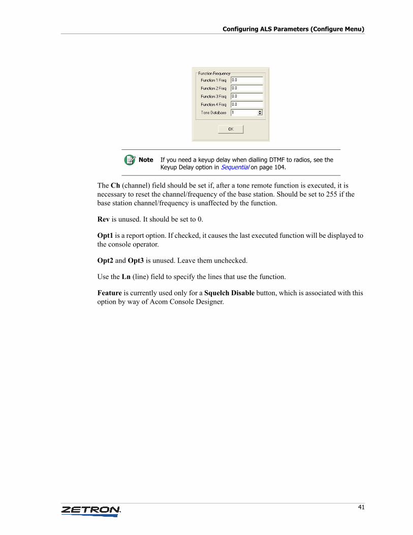
41
Configuring ALS Parameters (Configure Menu)
The Ch (channel) field should be set if, after a tone remote function is executed, it is necessary to reset the channel/frequency of the base station. Should be set to 255 if the base station channel/frequency is unaffected by the function.
Rev is unused. It should be set to 0.
Opt1 is a report option. If checked, it causes the last executed function will be displayed to the console operator.
Opt2 and Opt3 is unused. Leave them unchecked.
Use the Ln (line) field to specify the lines that use the function.
Feature is currently used only for a Squelch Disable button, which is associated with this option by way of Acom Console Designer.
Note If you need a keyup delay when dialling DTMF to radios, see the Keyup Delay option in Sequential on page 104.
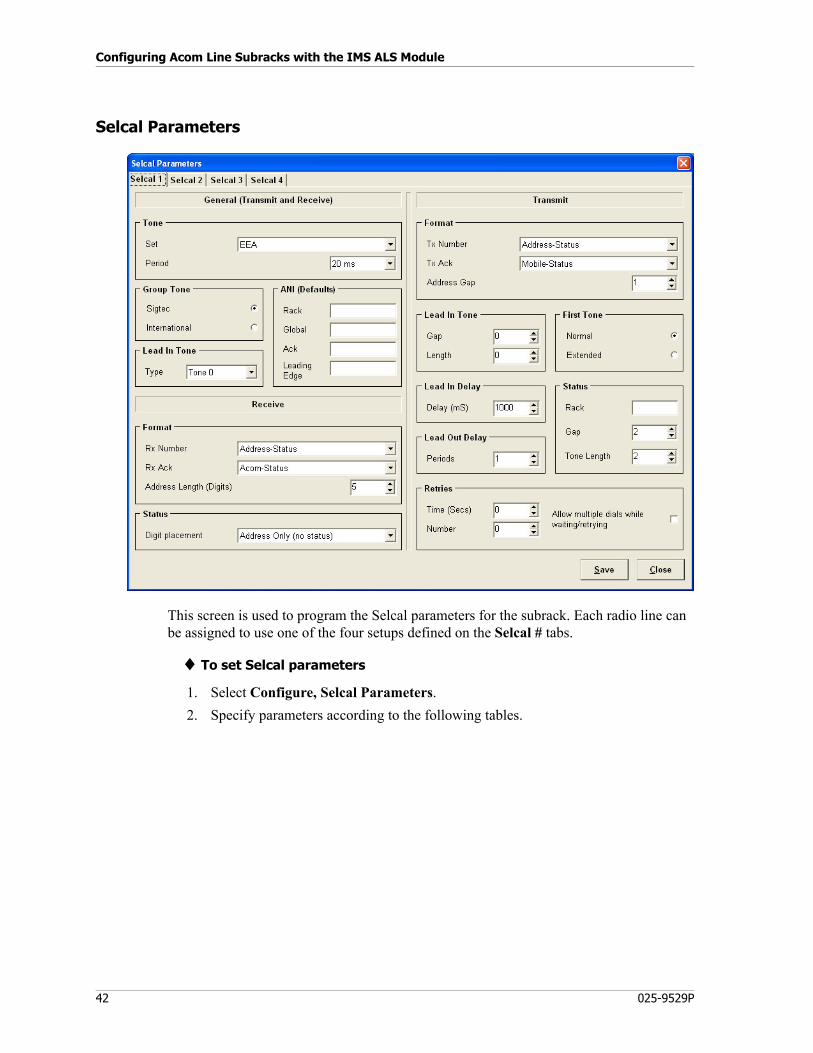
Configuring Acom Line Subracks with the IMS ALS Module
42 025-9529P
Selcal Parameters
This screen is used to program the Selcal parameters for the subrack. Each radio line can be assigned to use one of the four setups defined on the Selcal # tabs.
♦ To set Selcal parameters
1. Select Configure, Selcal Parameters.
2. Specify parameters according to the following tables.
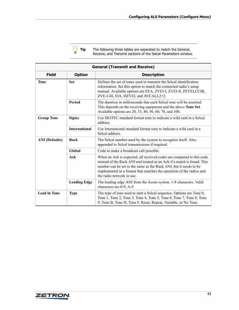
43
Configuring ALS Parameters (Configure Menu)
Tip The following three tables are separated to match the General, Receive, and Transmit sections of the Selcal Parameters window.
General (Transmit and Receive)
Field Option Description
Tone Set Defines the set of tones used to transmit the Selcal identification information. Set this option to match the connected radio’s setup manual. Available options are EEA, ZVEI-I, ZVEI-II, PZVEI,CCIR, ZVE-I-III, EIA, DZVEI, and AVCALL2+2.
Period The duration in milliseconds that each Selcal tone will be asserted. This depends on the receiving equipment and the above Tone Set. Available options are 20, 33, 40, 50, 60, 70, and 100.
Group Tone Sigtec Use SIGTEC standard format tone to indicate a wild card in a Selcal address.
International Use International standard format tone to indicate a wild card in a Selcal address.
ANI (Defaults) Rack The Selcal number used by the system to recognize itself. Also appended to Selcal transmissions if required.
Global Code to make a broadcast call possible.
Ack When an Ack is expected, all received codes are compared to this code instead of the Rack ANI and treated as an Ack if a match is found. This number can be set to the same as the Rack ANI, but it needs to be implemented in a format that matches the operation of the radios and the radio network in use.
Leading Edge The leading edge ANI from the Acom system. 1-8 characters. Valid characters are 0-9, A-F.
Lead in Tone Type The type of tone used to start a Selcal sequence. Options are Tone 0, Tone 1, Tone 2, Tone 3, Tone 4, Tone 5, Tone 6, Tone 7, Tone 8, Tone 9, Tone B, Tone D, Tone F, Reset, Repeat, Variable, or No Tone.
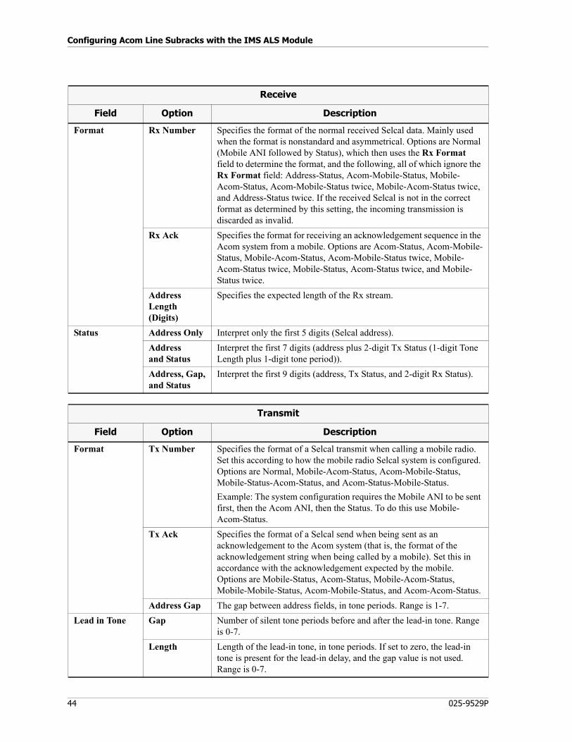
Configuring Acom Line Subracks with the IMS ALS Module
44 025-9529P
Receive
Field Option Description
Format Rx Number Specifies the format of the normal received Selcal data. Mainly used when the format is nonstandard and asymmetrical. Options are Normal (Mobile ANI followed by Status), which then uses the Rx Format field to determine the format, and the following, all of which ignore the Rx Format field: Address-Status, Acom-Mobile-Status, Mobile-Acom-Status, Acom-Mobile-Status twice, Mobile-Acom-Status twice, and Address-Status twice. If the received Selcal is not in the correct format as determined by this setting, the incoming transmission is discarded as invalid.
Rx Ack Specifies the format for receiving an acknowledgement sequence in the Acom system from a mobile. Options are Acom-Status, Acom-Mobile-Status, Mobile-Acom-Status, Acom-Mobile-Status twice, Mobile-Acom-Status twice, Mobile-Status, Acom-Status twice, and Mobile-Status twice.
Address Length (Digits)
Specifies the expected length of the Rx stream.
Status Address Only Interpret only the first 5 digits (Selcal address).
Address and Status
Interpret the first 7 digits (address plus 2-digit Tx Status (1-digit Tone Length plus 1-digit tone period)).
Address, Gap,and Status
Interpret the first 9 digits (address, Tx Status, and 2-digit Rx Status).
Transmit
Field Option Description
Format Tx Number Specifies the format of a Selcal transmit when calling a mobile radio. Set this according to how the mobile radio Selcal system is configured. Options are Normal, Mobile-Acom-Status, Acom-Mobile-Status, Mobile-Status-Acom-Status, and Acom-Status-Mobile-Status.
Example: The system configuration requires the Mobile ANI to be sent first, then the Acom ANI, then the Status. To do this use Mobile-Acom-Status.
Tx Ack Specifies the format of a Selcal send when being sent as an acknowledgement to the Acom system (that is, the format of the acknowledgement string when being called by a mobile). Set this in accordance with the acknowledgement expected by the mobile. Options are Mobile-Status, Acom-Status, Mobile-Acom-Status, Mobile-Mobile-Status, Acom-Mobile-Status, and Acom-Acom-Status.
Address Gap The gap between address fields, in tone periods. Range is 1-7.
Lead in Tone Gap Number of silent tone periods before and after the lead-in tone. Range is 0-7.
Length Length of the lead-in tone, in tone periods. If set to zero, the lead-in tone is present for the lead-in delay, and the gap value is not used. Range is 0-7.
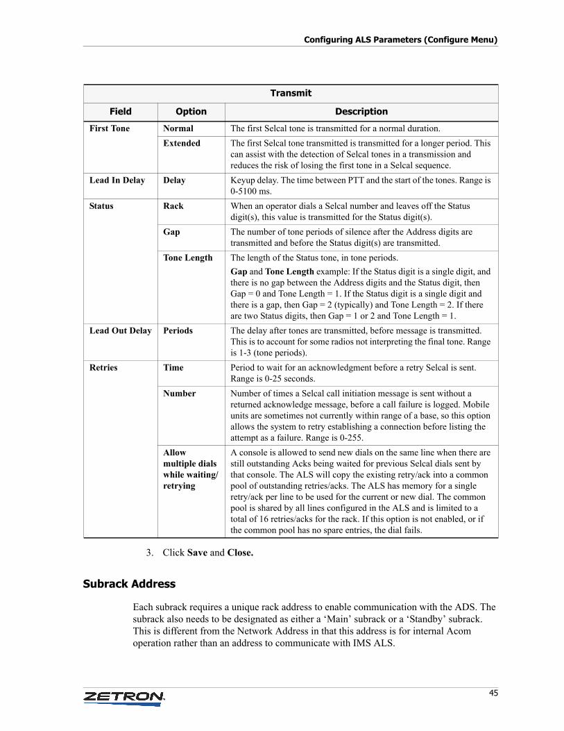
45
Configuring ALS Parameters (Configure Menu)
3. Click Save and Close.
Subrack Address
Each subrack requires a unique rack address to enable communication with the ADS. The subrack also needs to be designated as either a ‘Main’ subrack or a ‘Standby’ subrack. This is different from the Network Address in that this address is for internal Acom operation rather than an address to communicate with IMS ALS.
First Tone Normal The first Selcal tone is transmitted for a normal duration.
Extended The first Selcal tone transmitted is transmitted for a longer period. This can assist with the detection of Selcal tones in a transmission and reduces the risk of losing the first tone in a Selcal sequence.
Lead In Delay Delay Keyup delay. The time between PTT and the start of the tones. Range is 0-5100 ms.
Status Rack When an operator dials a Selcal number and leaves off the Status digit(s), this value is transmitted for the Status digit(s).
Gap The number of tone periods of silence after the Address digits are transmitted and before the Status digit(s) are transmitted.
Tone Length The length of the Status tone, in tone periods.
Gap and Tone Length example: If the Status digit is a single digit, and there is no gap between the Address digits and the Status digit, then Gap = 0 and Tone Length = 1. If the Status digit is a single digit and there is a gap, then Gap = 2 (typically) and Tone Length = 2. If there are two Status digits, then Gap = 1 or 2 and Tone Length = 1.
Lead Out Delay Periods The delay after tones are transmitted, before message is transmitted. This is to account for some radios not interpreting the final tone. Range is 1-3 (tone periods).
Retries Time Period to wait for an acknowledgment before a retry Selcal is sent. Range is 0-25 seconds.
Number Number of times a Selcal call initiation message is sent without a returned acknowledge message, before a call failure is logged. Mobile units are sometimes not currently within range of a base, so this option allows the system to retry establishing a connection before listing the attempt as a failure. Range is 0-255.
Allow multiple dials while waiting/retrying
A console is allowed to send new dials on the same line when there are still outstanding Acks being waited for previous Selcal dials sent by that console. The ALS will copy the existing retry/ack into a common pool of outstanding retries/acks. The ALS has memory for a single retry/ack per line to be used for the current or new dial. The common pool is shared by all lines configured in the ALS and is limited to a total of 16 retries/acks for the rack. If this option is not enabled, or if the common pool has no spare entries, the dial fails.
Transmit
Field Option Description
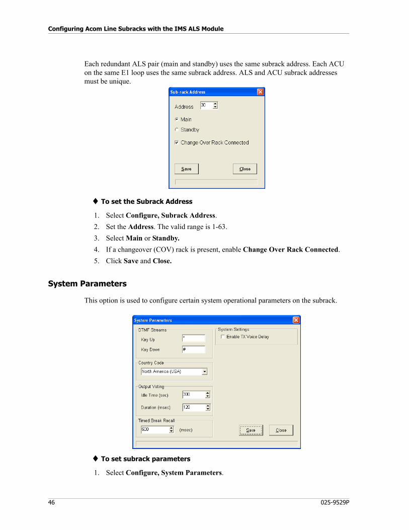
Configuring Acom Line Subracks with the IMS ALS Module
46 025-9529P
Each redundant ALS pair (main and standby) uses the same subrack address. Each ACU on the same E1 loop uses the same subrack address. ALS and ACU subrack addresses must be unique.
♦ To set the Subrack Address
1. Select Configure, Subrack Address.
2. Set the Address. The valid range is 1-63.
3. Select Main or Standby.
4. If a changeover (COV) rack is present, enable Change Over Rack Connected.
5. Click Save and Close.
System Parameters
This option is used to configure certain system operational parameters on the subrack.
♦ To set subrack parameters
1. Select Configure, System Parameters.
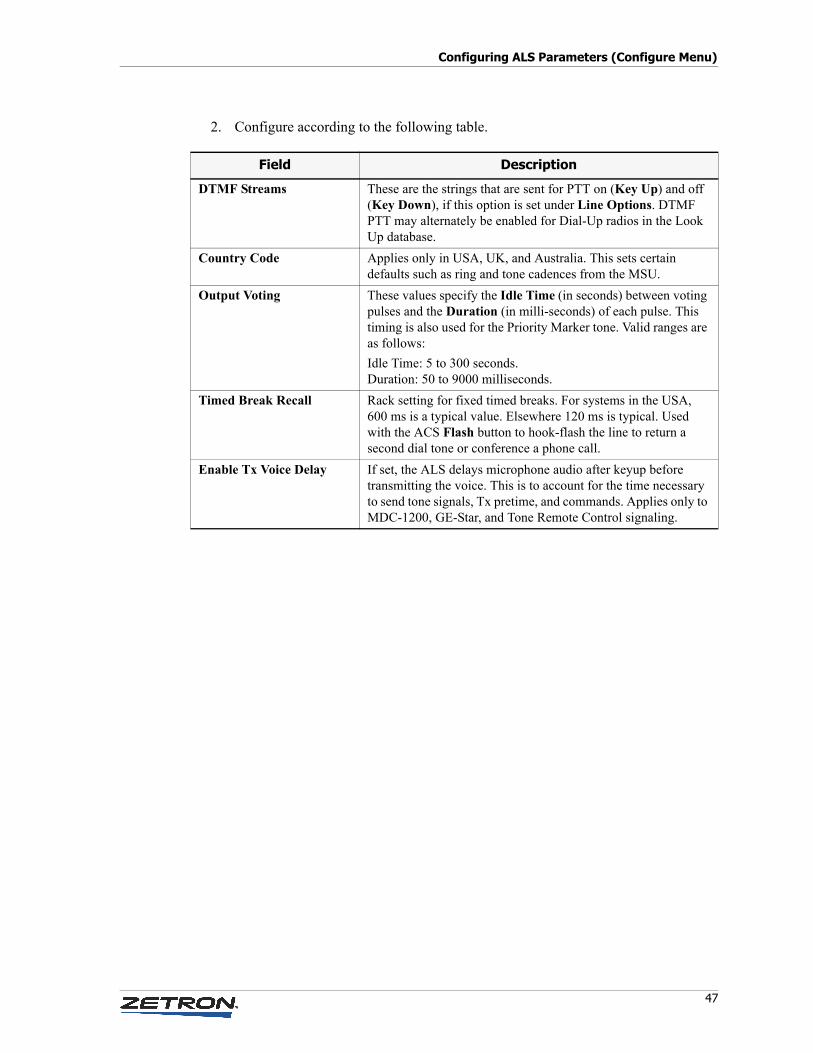
47
Configuring ALS Parameters (Configure Menu)
2. Configure according to the following table.
Field Description
DTMF Streams These are the strings that are sent for PTT on (Key Up) and off (Key Down), if this option is set under Line Options. DTMF PTT may alternately be enabled for Dial-Up radios in the Look Up database.
Country Code Applies only in USA, UK, and Australia. This sets certain defaults such as ring and tone cadences from the MSU.
Output Voting These values specify the Idle Time (in seconds) between voting pulses and the Duration (in milli-seconds) of each pulse. This timing is also used for the Priority Marker tone. Valid ranges are as follows:
Idle Time: 5 to 300 seconds.Duration: 50 to 9000 milliseconds.
Timed Break Recall Rack setting for fixed timed breaks. For systems in the USA, 600 ms is a typical value. Elsewhere 120 ms is typical. Used with the ACS Flash button to hook-flash the line to return a second dial tone or conference a phone call.
Enable Tx Voice Delay If set, the ALS delays microphone audio after keyup before transmitting the voice. This is to account for the time necessary to send tone signals, Tx pretime, and commands. Applies only to MDC-1200, GE-Star, and Tone Remote Control signaling.
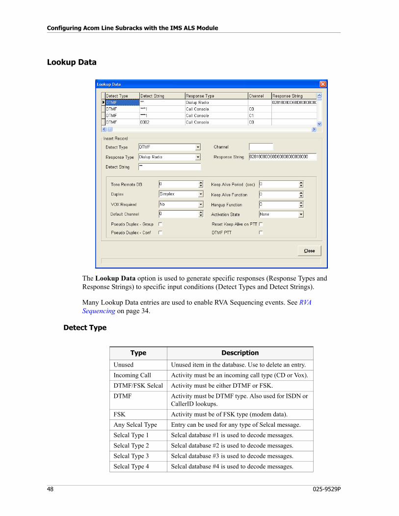
Configuring Acom Line Subracks with the IMS ALS Module
48 025-9529P
Lookup Data
The Lookup Data option is used to generate specific responses (Response Types and Response Strings) to specific input conditions (Detect Types and Detect Strings).
Many Lookup Data entries are used to enable RVA Sequencing events. See RVA Sequencing on page 34.
Detect Type
Type Description
Unused Unused item in the database. Use to delete an entry.
Incoming Call Activity must be an incoming call type (CD or Vox).
DTMF/FSK Selcal Activity must be either DTMF or FSK.
DTMF Activity must be DTMF type. Also used for ISDN or CallerID lookups.
FSK Activity must be of FSK type (modem data).
Any Selcal Type Entry can be used for any type of Selcal message.
Selcal Type 1 Selcal database #1 is used to decode messages.
Selcal Type 2 Selcal database #2 is used to decode messages.
Selcal Type 3 Selcal database #3 is used to decode messages.
Selcal Type 4 Selcal database #4 is used to decode messages.
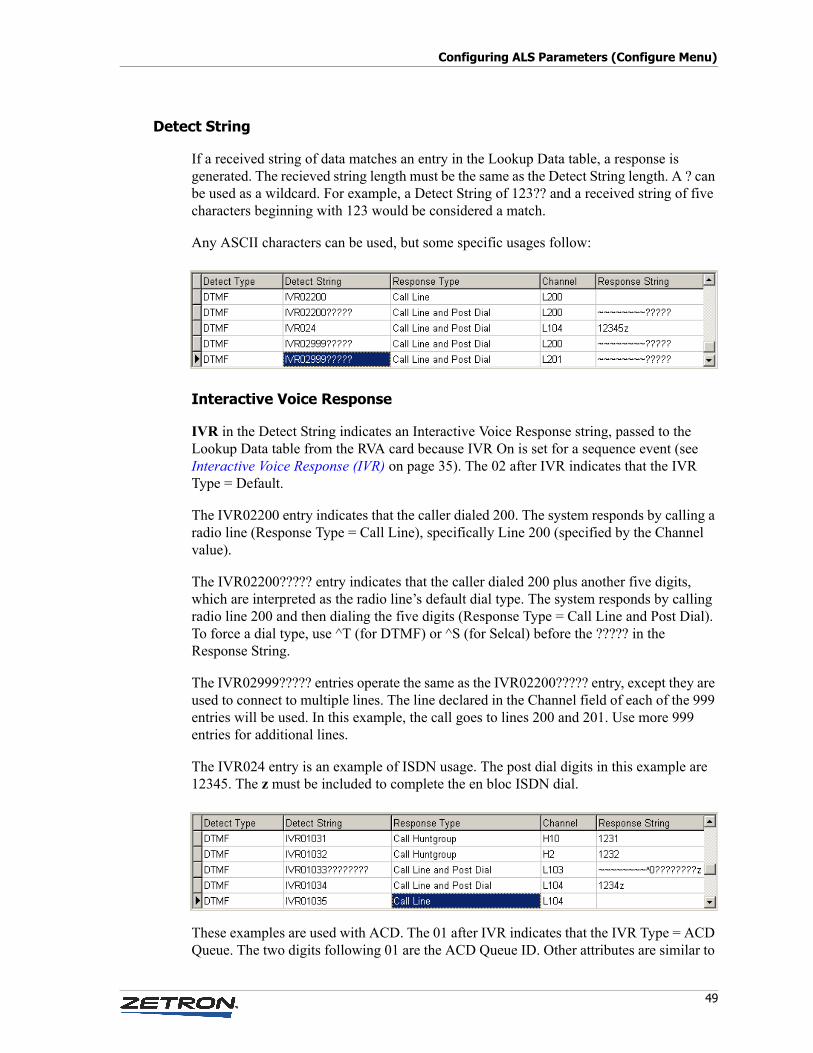
49
Configuring ALS Parameters (Configure Menu)
Detect String
If a received string of data matches an entry in the Lookup Data table, a response is generated. The recieved string length must be the same as the Detect String length. A ? can be used as a wildcard. For example, a Detect String of 123?? and a received string of five characters beginning with 123 would be considered a match.
Any ASCII characters can be used, but some specific usages follow:
Interactive Voice Response
IVR in the Detect String indicates an Interactive Voice Response string, passed to the Lookup Data table from the RVA card because IVR On is set for a sequence event (see Interactive Voice Response (IVR) on page 35). The 02 after IVR indicates that the IVR Type = Default.
The IVR02200 entry indicates that the caller dialed 200. The system responds by calling a radio line (Response Type = Call Line), specifically Line 200 (specified by the Channel value).
The IVR02200????? entry indicates that the caller dialed 200 plus another five digits, which are interpreted as the radio line’s default dial type. The system responds by calling radio line 200 and then dialing the five digits (Response Type = Call Line and Post Dial). To force a dial type, use ^T (for DTMF) or ^S (for Selcal) before the ????? in the Response String.
The IVR02999????? entries operate the same as the IVR02200????? entry, except they are used to connect to multiple lines. The line declared in the Channel field of each of the 999 entries will be used. In this example, the call goes to lines 200 and 201. Use more 999 entries for additional lines.
The IVR024 entry is an example of ISDN usage. The post dial digits in this example are 12345. The z must be included to complete the en bloc ISDN dial.
These examples are used with ACD. The 01 after IVR indicates that the IVR Type = ACD Queue. The two digits following 01 are the ACD Queue ID. Other attributes are similar to
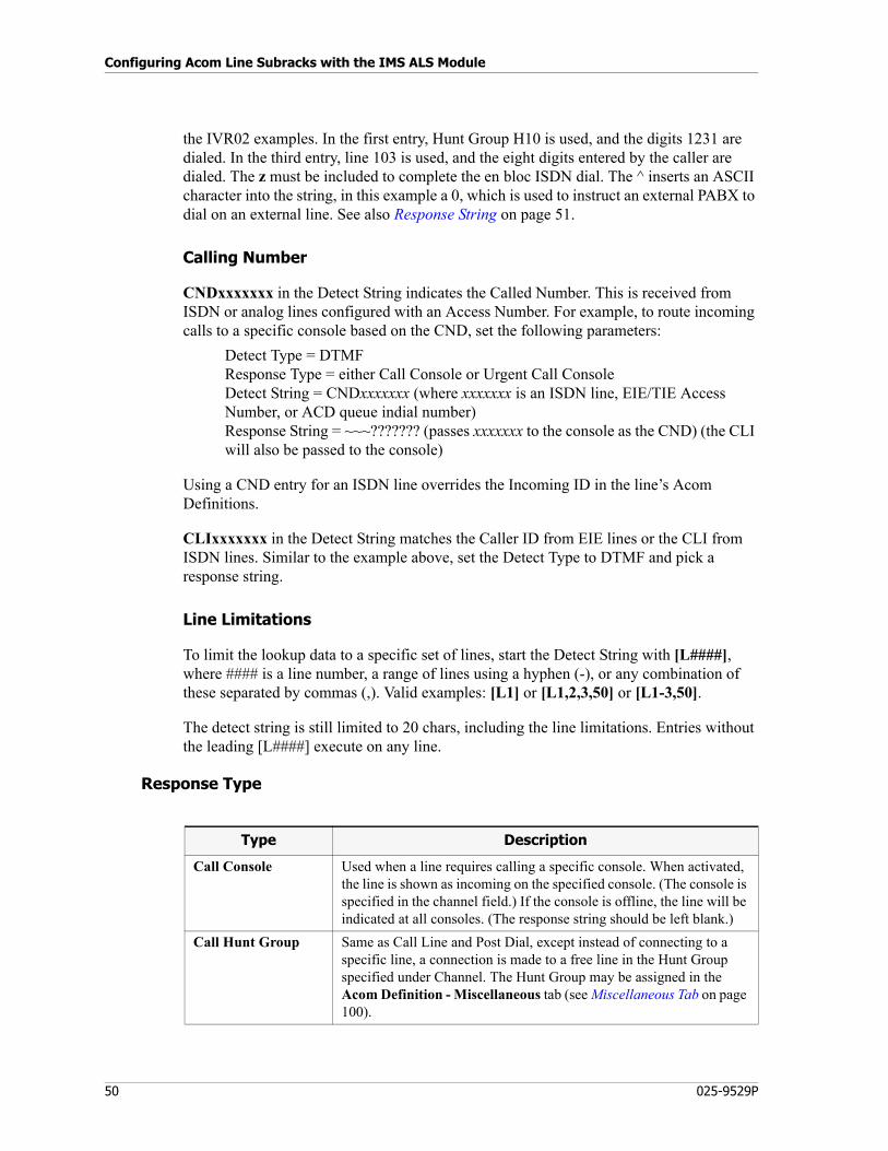
Configuring Acom Line Subracks with the IMS ALS Module
50 025-9529P
the IVR02 examples. In the first entry, Hunt Group H10 is used, and the digits 1231 are dialed. In the third entry, line 103 is used, and the eight digits entered by the caller are dialed. The z must be included to complete the en bloc ISDN dial. The ^ inserts an ASCII character into the string, in this example a 0, which is used to instruct an external PABX to dial on an external line. See also Response String on page 51.
Calling Number
CNDxxxxxxx in the Detect String indicates the Called Number. This is received from ISDN or analog lines configured with an Access Number. For example, to route incoming calls to a specific console based on the CND, set the following parameters:
Detect Type = DTMFResponse Type = either Call Console or Urgent Call ConsoleDetect String = CNDxxxxxxx (where xxxxxxx is an ISDN line, EIE/TIE Access Number, or ACD queue indial number)Response String = ~~~??????? (passes xxxxxxx to the console as the CND) (the CLI will also be passed to the console)
Using a CND entry for an ISDN line overrides the Incoming ID in the line’s Acom Definitions.
CLIxxxxxxx in the Detect String matches the Caller ID from EIE lines or the CLI from ISDN lines. Similar to the example above, set the Detect Type to DTMF and pick a response string.
Line Limitations
To limit the lookup data to a specific set of lines, start the Detect String with [L####], where #### is a line number, a range of lines using a hyphen (-), or any combination of these separated by commas (,). Valid examples: [L1] or [L1,2,3,50] or [L1-3,50].
The detect string is still limited to 20 chars, including the line limitations. Entries without the leading [L####] execute on any line.
Response Type
Type Description
Call Console Used when a line requires calling a specific console. When activated, the line is shown as incoming on the specified console. (The console is specified in the channel field.) If the console is offline, the line will be indicated at all consoles. (The response string should be left blank.)
Call Hunt Group Same as Call Line and Post Dial, except instead of connecting to a specific line, a connection is made to a free line in the Hunt Group specified under Channel. The Hunt Group may be assigned in the Acom Definition - Miscellaneous tab (see Miscellaneous Tab on page 100).
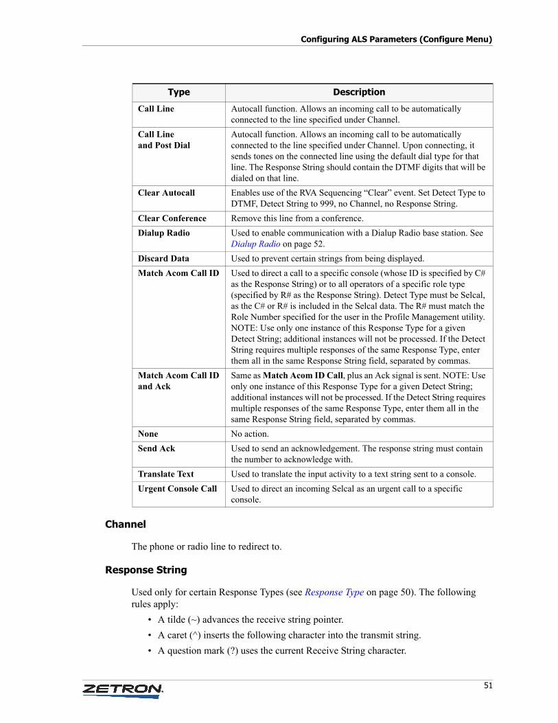
51
Configuring ALS Parameters (Configure Menu)
Channel
The phone or radio line to redirect to.
Response String
Used only for certain Response Types (see Response Type on page 50). The following rules apply:
• A tilde (~) advances the receive string pointer.
• A caret (^) inserts the following character into the transmit string.
• A question mark (?) uses the current Receive String character.
Call Line Autocall function. Allows an incoming call to be automatically connected to the line specified under Channel.
Call Lineand Post Dial
Autocall function. Allows an incoming call to be automatically connected to the line specified under Channel. Upon connecting, it sends tones on the connected line using the default dial type for that line. The Response String should contain the DTMF digits that will be dialed on that line.
Clear Autocall Enables use of the RVA Sequencing “Clear” event. Set Detect Type to DTMF, Detect String to 999, no Channel, no Response String.
Clear Conference Remove this line from a conference.
Dialup Radio Used to enable communication with a Dialup Radio base station. See Dialup Radio on page 52.
Discard Data Used to prevent certain strings from being displayed.
Match Acom Call ID Used to direct a call to a specific console (whose ID is specified by C# as the Response String) or to all operators of a specific role type (specified by R# as the Response String). Detect Type must be Selcal, as the C# or R# is included in the Selcal data. The R# must match the Role Number specified for the user in the Profile Management utility. NOTE: Use only one instance of this Response Type for a given Detect String; additional instances will not be processed. If the Detect String requires multiple responses of the same Response Type, enter them all in the same Response String field, separated by commas.
Match Acom Call IDand Ack
Same as Match Acom ID Call, plus an Ack signal is sent. NOTE: Use only one instance of this Response Type for a given Detect String; additional instances will not be processed. If the Detect String requires multiple responses of the same Response Type, enter them all in the same Response String field, separated by commas.
None No action.
Send Ack Used to send an acknowledgement. The response string must contain the number to acknowledge with.
Translate Text Used to translate the input activity to a text string sent to a console.
Urgent Console Call Used to direct an incoming Selcal as an urgent call to a specific console.
Type Description
Configuring Acom Line Subracks with the IMS ALS Module
52 025-9529P
• Any other character replaces a Receive String character.
• Maximum length of string is 20 characters.
For Dialup Radio, this string is automatically generated by Acom. Do not edit it.
C# is a console ID. R# is an operator role type. C and R must be upper case. For example, the string “R2,C10-13” calls role 2 (regardless of console) and consoles 10 through 13; the string “R1,3-5” calls role 1 and roles 3 through 5 (regardless of console). This response string is only applicable for the response type Match Acom Call ID.
A single entry can be applied to multiple consoles by using the response string “[C######]”. Consoles can be listed individually using commas, as a range using a hyphen, or a mixture of the two. For example: “[C1,2,3,10-20]”. The maximum number of consoles is 40. This response string is only applicable for the following response types: Call Console, Urgent Call Console, and Translate Text.
Other strings are dial strings. A dial string may include a modifier at the beginning. If the response string has no dial modifier, the post dial is determined by the called line's default dial type setting. The dial modifier for DTMF is ^T. For Selcal it is ^S.
Dialup Radio
Almost all cities in the USA and Canada have dialup base stations and receivers that enable aircraft to make and receive phone calls. Acom can interface to base stations that include these radio types:
• Baker RDI-7000
• S-COM AGI200
• S-COM AGI1100
The figure under Lookup Data on page 48 illustrates a typical setup for the dialup radio feature. When Response Type is set to Dialup Radio, the Response String is automatically generated by Acom (do not edit it), and the fields in the lower half of the window appear. They only appear for the Dialup Radio feature.
♦ To insert a record
This is a generic example.
1. Select Configure.
2. Select Lookup Data.
3. Select an option from Detect Type section.
4. Type in a value in Detect String field in the Insert Record section.
5. Select an option from Response Type section.
6. Type in a value in Response String field in the Insert Record section.
7. Click Insert.
8. Click Save.
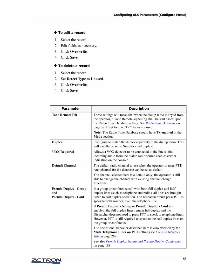
53
Configuring ALS Parameters (Configure Menu)
♦ To edit a record
1. Select the record.
2. Edit fields as necessary.
3. Click Overwrite.
4. Click Save.
♦ To delete a record
1. Select the record.
2. Set Detect Type to Unused.
3. Click Overwrite.
4. Click Save.
Parameter Description
Tone Remote DB These settings will mean that when the dialup radio is keyed from the operator, a Tone Remote signalling shall be sent based upon the Radio Tone Database setting. See Radio Tone Database on page 38. If set to 0, no TRC tones are used.
Note: The Radio Tone Database should have Tx enabled in the Mode section.
Duplex Configure to match the duplex capability of the dialup radio. This will usually be set to Simplex (half duplex).
VOX Required Allows a VOX detector to be connected to the line so that incoming audio from the dialup radio source enables carrier indication on the console.
Default Channel The default radio channel to use when the operator presses PTT. Any channel fro the database can be set as default.
The channel selected here is a default only; the operator is still able to change the channel with existing channel change functions.
Pseudo Duplex - GroupandPseudo Duplex - Conf
In a group or conference call with both full duplex and half duplex lines (such as telephone and radio), all lines are brought down to half duplex operation. The Dispatcher must press PTT to speak to both sources, even the telephone line.
If Pseudo Duplex - Group or Pseudo Duplex - Conf are enabled, the full duplex lines remain full duplex and the Dispatcher does not need to press PTT to speak to telephone lines. However, PTT is still required to speak to the half duplex lines on the group or conference.
The operational behavior described here is also affected by the Mute Telephone Lines on PTT setting (see Console Interface Tab on page 267).
See also Pseudo Duplex Group and Pseudo Duplex Conference on page 188.
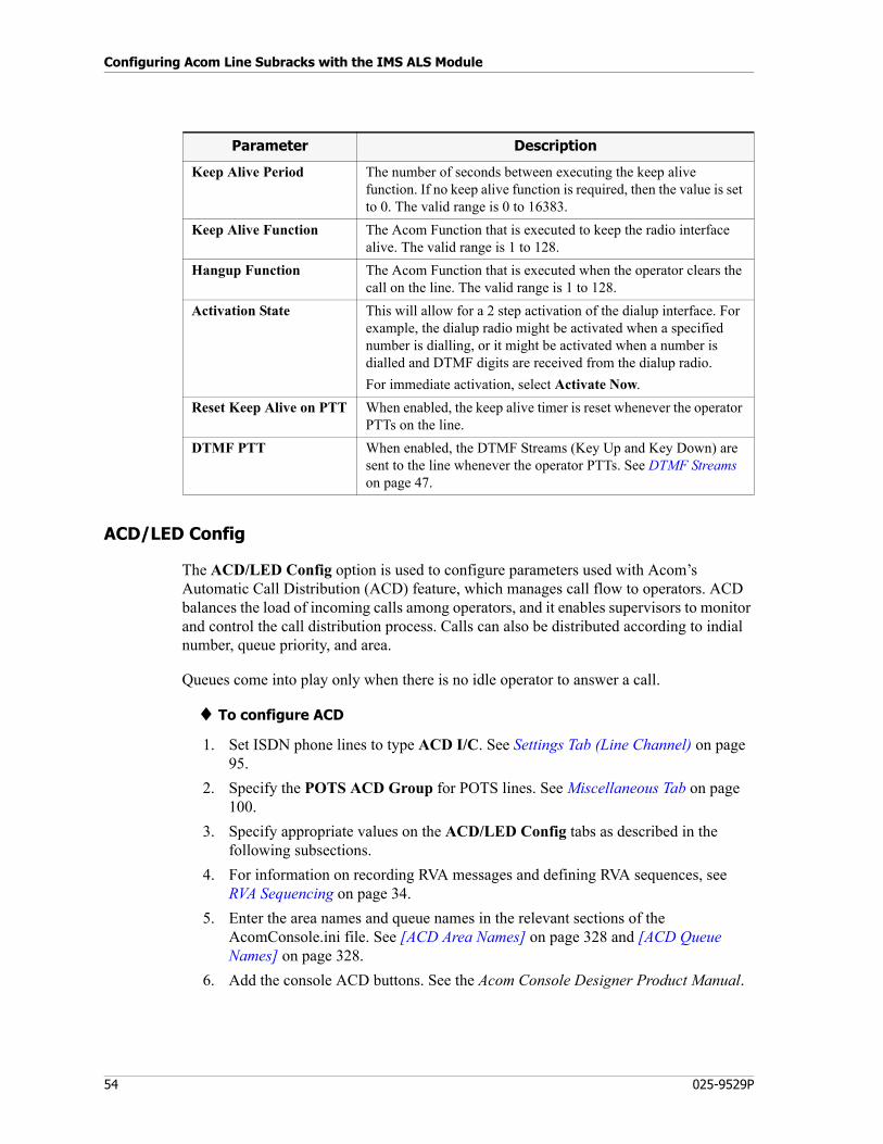
Configuring Acom Line Subracks with the IMS ALS Module
54 025-9529P
ACD/LED Config
The ACD/LED Config option is used to configure parameters used with Acom’s Automatic Call Distribution (ACD) feature, which manages call flow to operators. ACD balances the load of incoming calls among operators, and it enables supervisors to monitor and control the call distribution process. Calls can also be distributed according to indial number, queue priority, and area.
Queues come into play only when there is no idle operator to answer a call.
♦ To configure ACD
1. Set ISDN phone lines to type ACD I/C. See Settings Tab (Line Channel) on page 95.
2. Specify the POTS ACD Group for POTS lines. See Miscellaneous Tab on page 100.
3. Specify appropriate values on the ACD/LED Config tabs as described in the following subsections.
4. For information on recording RVA messages and defining RVA sequences, see RVA Sequencing on page 34.
5. Enter the area names and queue names in the relevant sections of the AcomConsole.ini file. See [ACD Area Names] on page 328 and [ACD Queue Names] on page 328.
6. Add the console ACD buttons. See the Acom Console Designer Product Manual.
Keep Alive Period The number of seconds between executing the keep alive function. If no keep alive function is required, then the value is set to 0. The valid range is 0 to 16383.
Keep Alive Function The Acom Function that is executed to keep the radio interface alive. The valid range is 1 to 128.
Hangup Function The Acom Function that is executed when the operator clears the call on the line. The valid range is 1 to 128.
Activation State This will allow for a 2 step activation of the dialup interface. For example, the dialup radio might be activated when a specified number is dialling, or it might be activated when a number is dialled and DTMF digits are received from the dialup radio.
For immediate activation, select Activate Now.
Reset Keep Alive on PTT When enabled, the keep alive timer is reset whenever the operator PTTs on the line.
DTMF PTT When enabled, the DTMF Streams (Key Up and Key Down) are sent to the line whenever the operator PTTs. See DTMF Streams on page 47.
Parameter Description
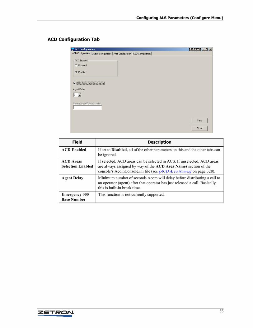
55
Configuring ALS Parameters (Configure Menu)
ACD Configuration Tab
Field Description
ACD Enabled If set to Disabled, all of the other parameters on this and the other tabs can be ignored.
ACD Areas Selection Enabled
If selected, ACD areas can be selected in ACS. If unselected, ACD areas are always assigned by way of the ACD Area Names section of the console’s AcomConsole.ini file (see [ACD Area Names] on page 328).
Agent Delay Minimum number of seconds Acom will delay before distributing a call to an operator (agent) after that operator has just released a call. Basically, this is built-in break time.
Emergency 000 Base Number
This function is not currently supported.
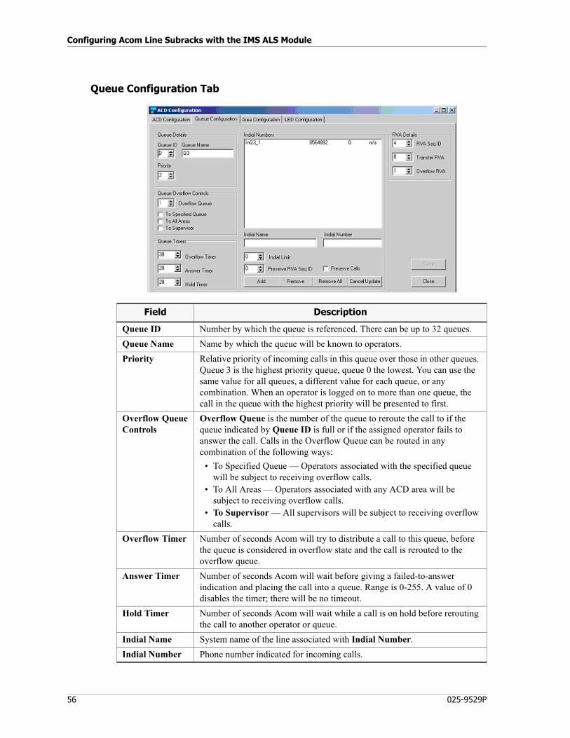
Configuring Acom Line Subracks with the IMS ALS Module
56 025-9529P
Queue Configuration Tab
Field Description
Queue ID Number by which the queue is referenced. There can be up to 32 queues.
Queue Name Name by which the queue will be known to operators.
Priority Relative priority of incoming calls in this queue over those in other queues. Queue 3 is the highest priority queue, queue 0 the lowest. You can use the same value for all queues, a different value for each queue, or any combination. When an operator is logged on to more than one queue, the call in the queue with the highest priority will be presented to first.
Overflow QueueControls
Overflow Queue is the number of the queue to reroute the call to if the queue indicated by Queue ID is full or if the assigned operator fails to answer the call. Calls in the Overflow Queue can be routed in any combination of the following ways:
• To Specified Queue — Operators associated with the specified queue will be subject to receiving overflow calls.
• To All Areas — Operators associated with any ACD area will be subject to receiving overflow calls.
• To Supervisor — All supervisors will be subject to receiving overflow calls.
Overflow Timer Number of seconds Acom will try to distribute a call to this queue, before the queue is considered in overflow state and the call is rerouted to the overflow queue.
Answer Timer Number of seconds Acom will wait before giving a failed-to-answer indication and placing the call into a queue. Range is 0-255. A value of 0 disables the timer; there will be no timeout.
Hold Timer Number of seconds Acom will wait while a call is on hold before rerouting the call to another operator or queue.
Indial Name System name of the line associated with Indial Number.
Indial Number Phone number indicated for incoming calls.
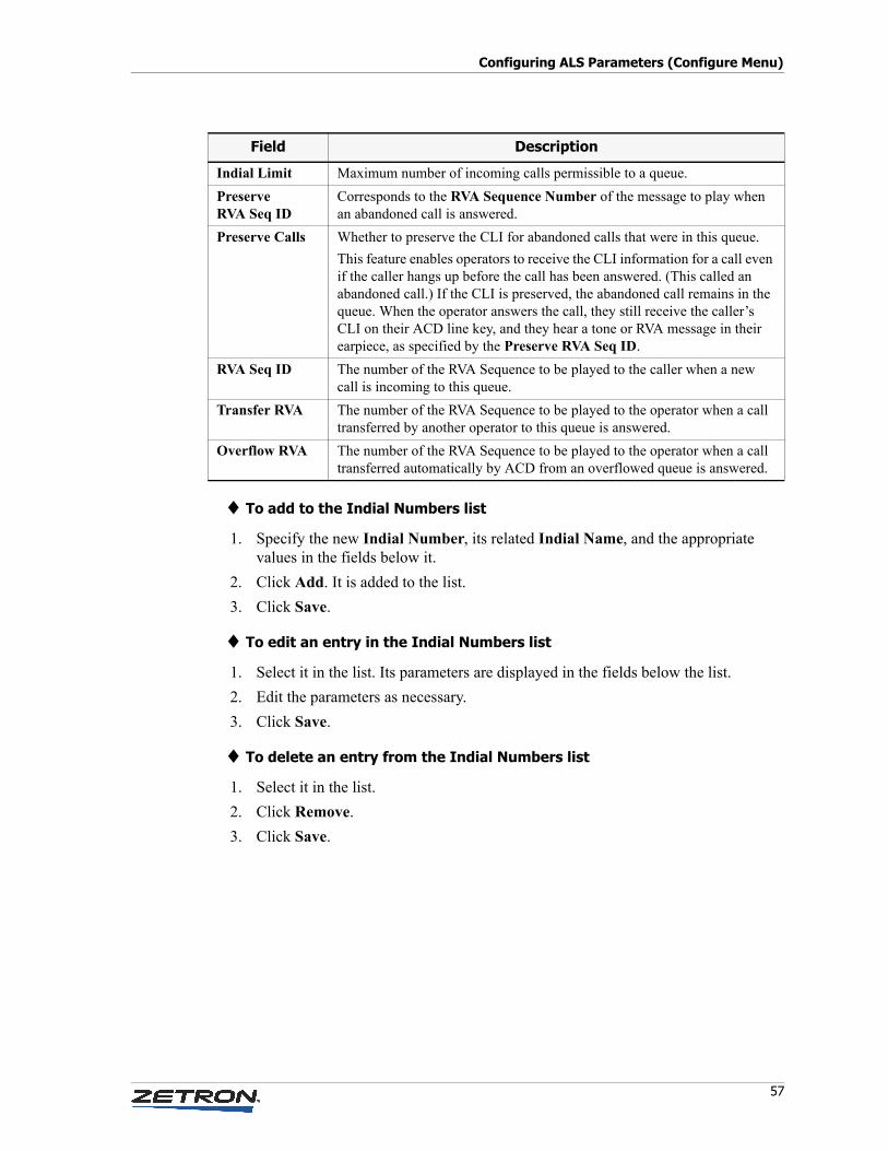
57
Configuring ALS Parameters (Configure Menu)
♦ To add to the Indial Numbers list
1. Specify the new Indial Number, its related Indial Name, and the appropriate values in the fields below it.
2. Click Add. It is added to the list.
3. Click Save.
♦ To edit an entry in the Indial Numbers list
1. Select it in the list. Its parameters are displayed in the fields below the list.
2. Edit the parameters as necessary.
3. Click Save.
♦ To delete an entry from the Indial Numbers list
1. Select it in the list.
2. Click Remove.
3. Click Save.
Indial Limit Maximum number of incoming calls permissible to a queue.
Preserve RVA Seq ID
Corresponds to the RVA Sequence Number of the message to play when an abandoned call is answered.
Preserve Calls Whether to preserve the CLI for abandoned calls that were in this queue.
This feature enables operators to receive the CLI information for a call even if the caller hangs up before the call has been answered. (This called an abandoned call.) If the CLI is preserved, the abandoned call remains in the queue. When the operator answers the call, they still receive the caller’s CLI on their ACD line key, and they hear a tone or RVA message in their earpiece, as specified by the Preserve RVA Seq ID.
RVA Seq ID The number of the RVA Sequence to be played to the caller when a new call is incoming to this queue.
Transfer RVA The number of the RVA Sequence to be played to the operator when a call transferred by another operator to this queue is answered.
Overflow RVA The number of the RVA Sequence to be played to the operator when a call transferred automatically by ACD from an overflowed queue is answered.
Field Description
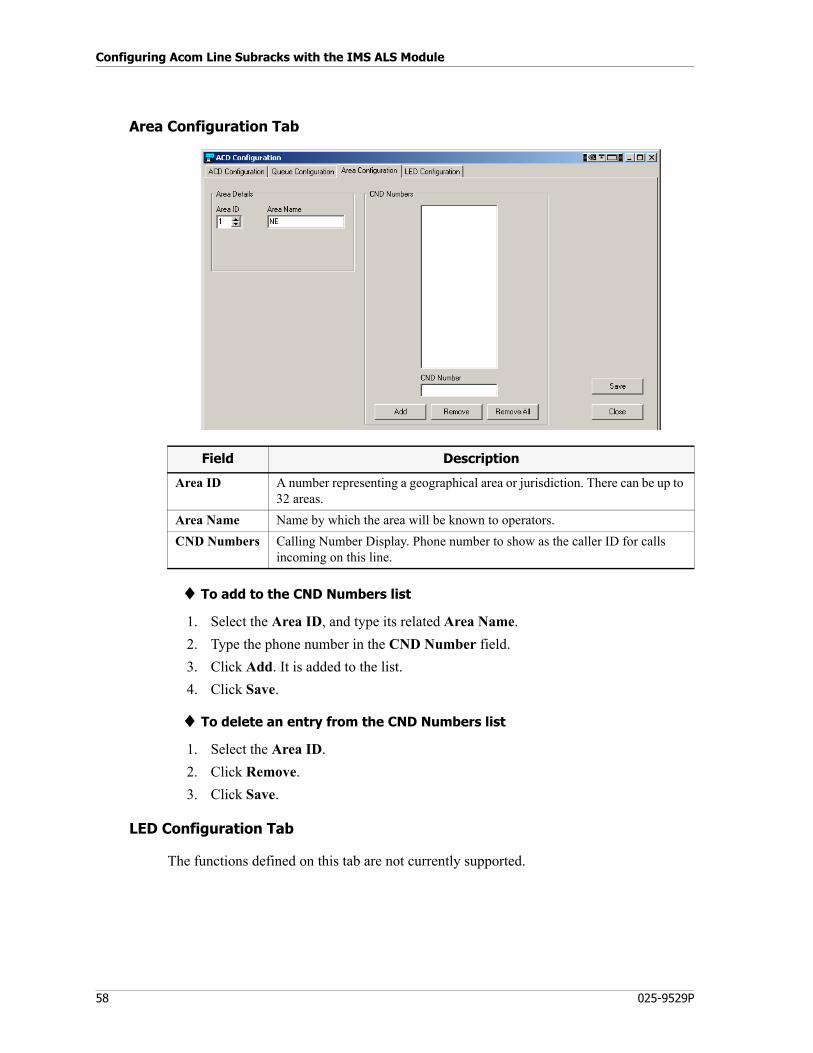
Configuring Acom Line Subracks with the IMS ALS Module
58 025-9529P
Area Configuration Tab
♦ To add to the CND Numbers list
1. Select the Area ID, and type its related Area Name.
2. Type the phone number in the CND Number field.
3. Click Add. It is added to the list.
4. Click Save.
♦ To delete an entry from the CND Numbers list
1. Select the Area ID.
2. Click Remove.
3. Click Save.
LED Configuration Tab
The functions defined on this tab are not currently supported.
Field Description
Area ID A number representing a geographical area or jurisdiction. There can be up to 32 areas.
Area Name Name by which the area will be known to operators.
CND Numbers Calling Number Display. Phone number to show as the caller ID for calls incoming on this line.
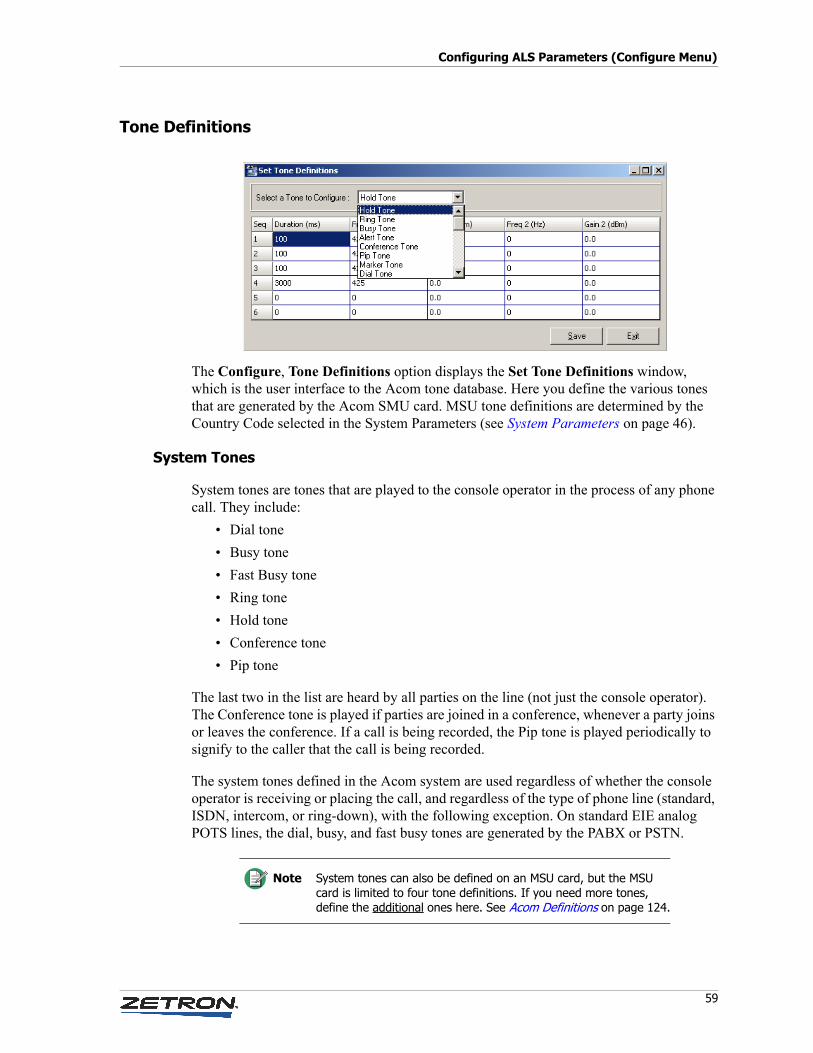
59
Configuring ALS Parameters (Configure Menu)
Tone Definitions
The Configure, Tone Definitions option displays the Set Tone Definitions window, which is the user interface to the Acom tone database. Here you define the various tones that are generated by the Acom SMU card. MSU tone definitions are determined by the Country Code selected in the System Parameters (see System Parameters on page 46).
System Tones
System tones are tones that are played to the console operator in the process of any phone call. They include:
• Dial tone
• Busy tone
• Fast Busy tone
• Ring tone
• Hold tone
• Conference tone
• Pip tone
The last two in the list are heard by all parties on the line (not just the console operator). The Conference tone is played if parties are joined in a conference, whenever a party joins or leaves the conference. If a call is being recorded, the Pip tone is played periodically to signify to the caller that the call is being recorded.
The system tones defined in the Acom system are used regardless of whether the console operator is receiving or placing the call, and regardless of the type of phone line (standard, ISDN, intercom, or ring-down), with the following exception. On standard EIE analog POTS lines, the dial, busy, and fast busy tones are generated by the PABX or PSTN.
Note System tones can also be defined on an MSU card, but the MSU card is limited to four tone definitions. If you need more tones, define the additional ones here. See Acom Definitions on page 124.
Configuring Acom Line Subracks with the IMS ALS Module
60 025-9529P
For each system tone that is defined here, an SMU resource must be configured. The Type of the resource must be set to the name of the tone, and the Tone Encoder field for that resource must be checked. See To configure an SMU resource on page 138.
Each system tone, whether defined here or on the MSU card, must also have a time slot assigned to it on the MCU3/4 card that is in slot 0. See LCB Connection Type on page 91.
System tones are not replicated across ISBs, with the possible exception of the ring tone. See Source Ring Tone From Bearer on page 222.
Marker Tone
Marker Tone defines how to generate a marker tone. This is the tone used when a Priority Marker is set on a line in ACS to indicate that the line is reserved for high-priority use.
♦ To configure Marker Tone
Prerequisite: An SMU Resource must be defined for Marker Tone. See To configure an SMU resource on page 138.
1. Go to the Configure, System Parameters window for the ALS (described under System Parameters on page 46).
2. Enter the Output Voting values. This has a direct relationship with the Voting values that are entered as part of the ALS System Parameters. The Vote Duration must be long enough to include the keyup sequence and the marker tone.
• Idle Vote — The time between generation of the tones.
• Vote Duration — How much time the channel is keyed. If tone remote radios are being used, this value must include the time it takes to send the High Level Guard, the Function Tone, and the Marker Tone.
For example, if you set Idle Vote to 60 seconds and Vote Duration to 1000 ms, every 60 seconds there will be a voting pulse of 1000 ms duration. However, if an operator PTTs the line, the Idle Vote timer will reset.
3. Configure the tone from the Configure, Tone Definitions window. Select Marker Tone. Enter the Duration, one Frequency, and one Gain.
Alert Tones
Alert tones fall into two categories and are defined and implemented in two ways.
• Those used in paging (known as paging alert tones or simply paging tones) are defined here and implemented by way of the Acom Paging Configuration utility.
Caution! For each system tone that is defined here, the equivalent system tone on the MSU card must not be defined. Right-click the MSU card, select Acom Definitions, and for each channel check the System tab to verify that the tone is not configured.
!
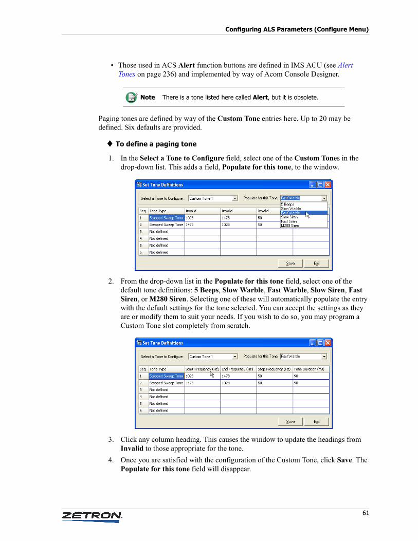
61
Configuring ALS Parameters (Configure Menu)
• Those used in ACS Alert function buttons are defined in IMS ACU (see Alert Tones on page 236) and implemented by way of Acom Console Designer.
Paging tones are defined by way of the Custom Tone entries here. Up to 20 may be defined. Six defaults are provided.
♦ To define a paging tone
1. In the Select a Tone to Configure field, select one of the Custom Tones in the drop-down list. This adds a field, Populate for this tone, to the window.
2. From the drop-down list in the Populate for this tone field, select one of the default tone definitions: 5 Beeps, Slow Warble, Fast Warble, Slow Siren, Fast Siren, or M280 Siren. Selecting one of these will automatically populate the entry with the default settings for the tone selected. You can accept the settings as they are or modify them to suit your needs. If you wish to do so, you may program a Custom Tone slot completely from scratch.
3. Click any column heading. This causes the window to update the headings from Invalid to those appropriate for the tone.
4. Once you are satisfied with the configuration of the Custom Tone, click Save. The Populate for this tone field will disappear.
Note There is a tone listed here called Alert, but it is obsolete.
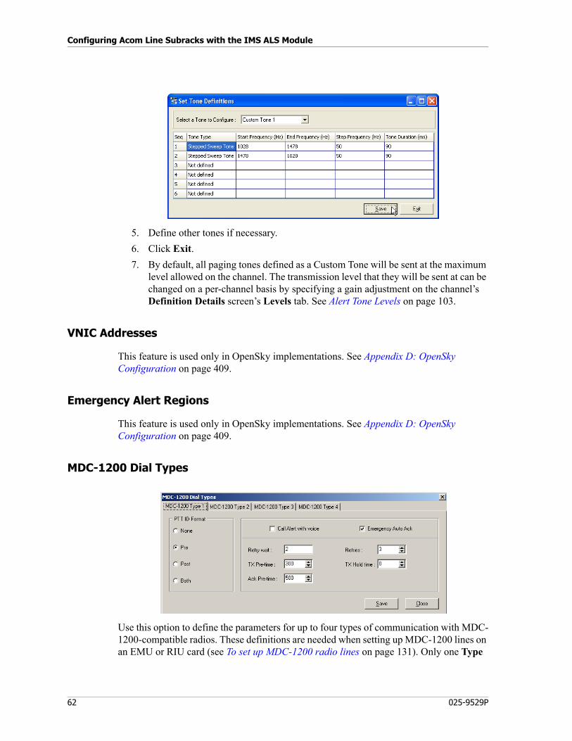
Configuring Acom Line Subracks with the IMS ALS Module
62 025-9529P
5. Define other tones if necessary.
6. Click Exit.
7. By default, all paging tones defined as a Custom Tone will be sent at the maximum level allowed on the channel. The transmission level that they will be sent at can be changed on a per-channel basis by specifying a gain adjustment on the channel’s Definition Details screen’s Levels tab. See Alert Tone Levels on page 103.
VNIC Addresses
This feature is used only in OpenSky implementations. See Appendix D: OpenSky Configuration on page 409.
Emergency Alert Regions
This feature is used only in OpenSky implementations. See Appendix D: OpenSky Configuration on page 409.
MDC-1200 Dial Types
Use this option to define the parameters for up to four types of communication with MDC-1200-compatible radios. These definitions are needed when setting up MDC-1200 lines on an EMU or RIU card (see To set up MDC-1200 radio lines on page 131). Only one Type
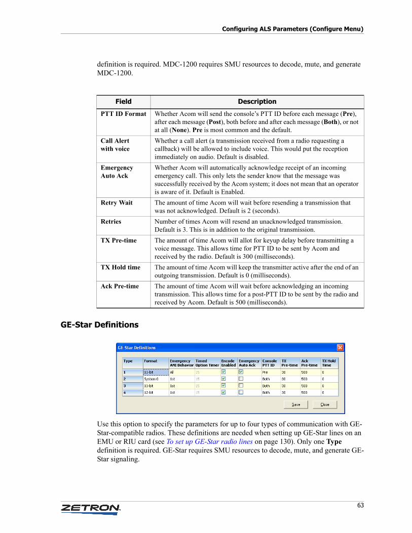
63
Configuring ALS Parameters (Configure Menu)
definition is required. MDC-1200 requires SMU resources to decode, mute, and generate MDC-1200.
GE-Star Definitions
Use this option to specify the parameters for up to four types of communication with GE-Star-compatible radios. These definitions are needed when setting up GE-Star lines on an EMU or RIU card (see To set up GE-Star radio lines on page 130). Only one Type definition is required. GE-Star requires SMU resources to decode, mute, and generate GE-Star signaling.
Field Description
PTT ID Format Whether Acom will send the console’s PTT ID before each message (Pre), after each message (Post), both before and after each message (Both), or not at all (None). Pre is most common and the default.
Call Alert with voice
Whether a call alert (a transmission received from a radio requesting a callback) will be allowed to include voice. This would put the reception immediately on audio. Default is disabled.
Emergency Auto Ack
Whether Acom will automatically acknowledge receipt of an incoming emergency call. This only lets the sender know that the message was successfully received by the Acom system; it does not mean that an operator is aware of it. Default is Enabled.
Retry Wait The amount of time Acom will wait before resending a transmission that was not acknowledged. Default is 2 (seconds).
Retries Number of times Acom will resend an unacknowledged transmission. Default is 3. This is in addition to the original transmission.
TX Pre-time The amount of time Acom will allot for keyup delay before transmitting a voice message. This allows time for PTT ID to be sent by Acom and received by the radio. Default is 300 (milliseconds).
TX Hold time The amount of time Acom will keep the transmitter active after the end of an outgoing transmission. Default is 0 (milliseconds).
Ack Pre-time The amount of time Acom will wait before acknowledging an incoming transmission. This allows time for a post-PTT ID to be sent by the radio and received by Acom. Default is 500 (milliseconds).
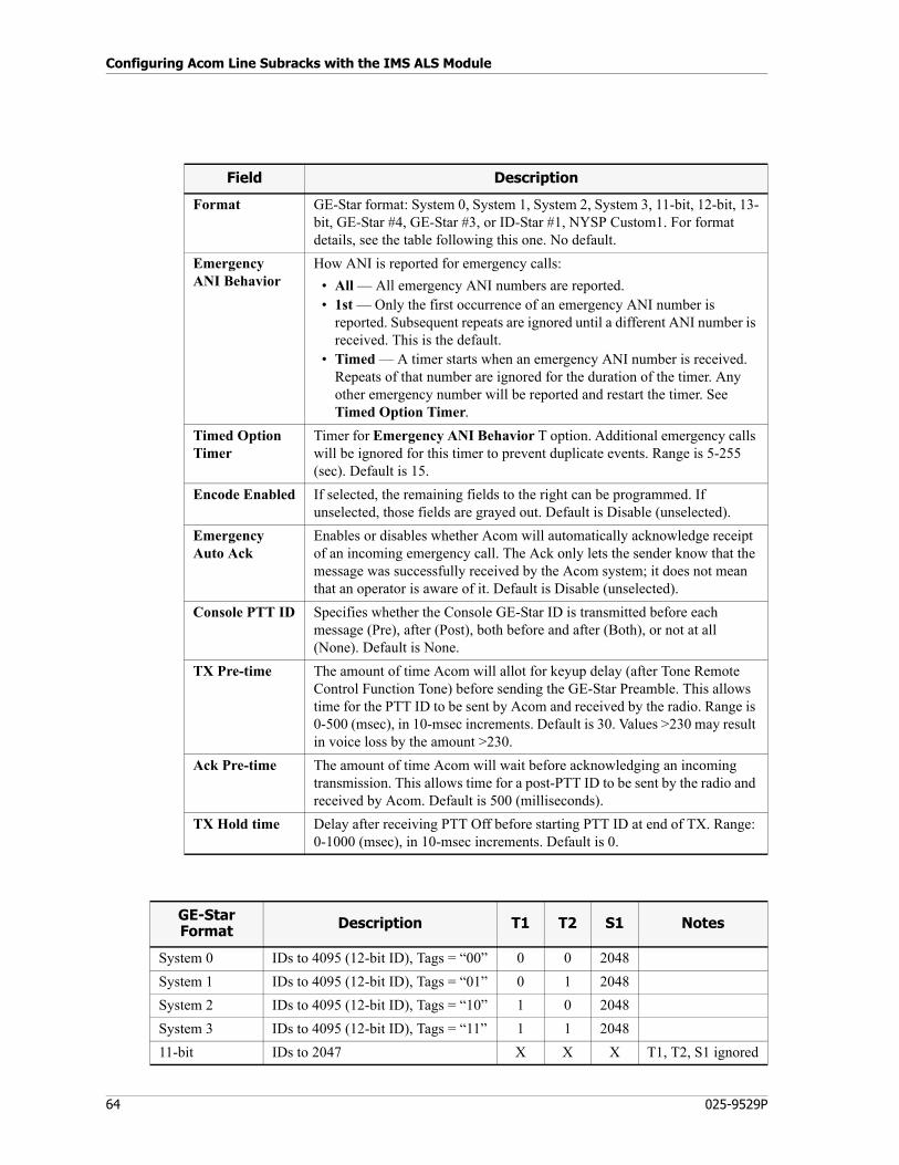
Configuring Acom Line Subracks with the IMS ALS Module
64 025-9529P
Field Description
Format GE-Star format: System 0, System 1, System 2, System 3, 11-bit, 12-bit, 13-bit, GE-Star #4, GE-Star #3, or ID-Star #1, NYSP Custom1. For format details, see the table following this one. No default.
Emergency ANI Behavior
How ANI is reported for emergency calls:
• All — All emergency ANI numbers are reported.• 1st — Only the first occurrence of an emergency ANI number is
reported. Subsequent repeats are ignored until a different ANI number is received. This is the default.
• Timed — A timer starts when an emergency ANI number is received. Repeats of that number are ignored for the duration of the timer. Any other emergency number will be reported and restart the timer. See Timed Option Timer.
Timed Option Timer
Timer for Emergency ANI Behavior T option. Additional emergency calls will be ignored for this timer to prevent duplicate events. Range is 5-255 (sec). Default is 15.
Encode Enabled If selected, the remaining fields to the right can be programmed. If unselected, those fields are grayed out. Default is Disable (unselected).
Emergency Auto Ack
Enables or disables whether Acom will automatically acknowledge receipt of an incoming emergency call. The Ack only lets the sender know that the message was successfully received by the Acom system; it does not mean that an operator is aware of it. Default is Disable (unselected).
Console PTT ID Specifies whether the Console GE-Star ID is transmitted before each message (Pre), after (Post), both before and after (Both), or not at all (None). Default is None.
TX Pre-time The amount of time Acom will allot for keyup delay (after Tone Remote Control Function Tone) before sending the GE-Star Preamble. This allows time for the PTT ID to be sent by Acom and received by the radio. Range is 0-500 (msec), in 10-msec increments. Default is 30. Values >230 may result in voice loss by the amount >230.
Ack Pre-time The amount of time Acom will wait before acknowledging an incoming transmission. This allows time for a post-PTT ID to be sent by the radio and received by Acom. Default is 500 (milliseconds).
TX Hold time Delay after receiving PTT Off before starting PTT ID at end of TX. Range: 0-1000 (msec), in 10-msec increments. Default is 0.
GE-StarFormat Description T1 T2 S1 Notes
System 0 IDs to 4095 (12-bit ID), Tags = “00” 0 0 2048
System 1 IDs to 4095 (12-bit ID), Tags = “01” 0 1 2048
System 2 IDs to 4095 (12-bit ID), Tags = “10” 1 0 2048
System 3 IDs to 4095 (12-bit ID), Tags = “11” 1 1 2048
11-bit IDs to 2047 X X X T1, T2, S1 ignored
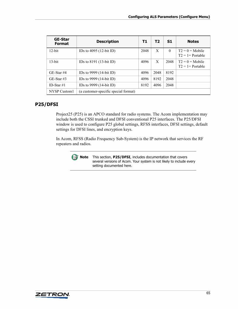
65
Configuring ALS Parameters (Configure Menu)
P25/DFSI
Project25 (P25) is an APCO standard for radio systems. The Acom implementation may include both the CSSI trunked and DFSI conventional P25 interfaces. The P25/DFSI window is used to configure P25 global settings, RFSS interfaces, DFSI settings, default settings for DFSI lines, and encryption keys.
In Acom, RFSS (Radio Frequency Sub-System) is the IP network that services the RF repeaters and radios.
12-bit IDs to 4095 (12-bit ID) 2048 X 0 T2 = 0 = MobileT2 = 1= Portable
13-bit IDs to 8191 (13-bit ID) 4096 X 2048 T2 = 0 = MobileT2 = 1= Portable
GE-Star #4 IDs to 9999 (14-bit ID) 4096 2048 8192
GE-Star #3 IDs to 9999 (14-bit ID) 4096 8192 2048
ID-Star #1 IDs to 9999 (14-bit ID) 8192 4096 2048
NYSP Custom1 (a customer-specific special format)
GE-StarFormat Description T1 T2 S1 Notes
Note This section, P25/DFSI, includes documentation that covers several versions of Acom. Your system is not likely to include every setting documented here.
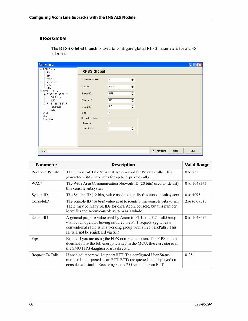
Configuring Acom Line Subracks with the IMS ALS Module
66 025-9529P
RFSS Global
The RFSS Global branch is used to configure global RFSS parameters for a CSSI interface.
Parameter Description Valid Range
Reserved Private The number of TalkPaths that are reserved for Private Calls. This guarantees SMU talkpaths for up to X private calls.
0 to 255
WACN The Wide Area Communication Network ID (20 bits) used to identify this console subsystem.
0 to 1048575
SystemID The System ID (12 bits) value used to identify this console subsystem. 0 to 4095
ConsoleID The console ID (16 bits) value used to identify this console subsystem. There may be many SUIDs for each Acom console, but this number identifies the Acom console system as a whole.
256 to 65535
DefaultID A general purpose value used by Acom to PTT on a P25 TalkGroup without an operator having initiated the PTT request. (eg when a conventional radio is in a working group with a P25 TalkPath). This ID will not be registered via SIP.
0 to 1048575
Fips Enable if you are using the FIPS-compliant option. The FIPS option does not store the full encryption key in the MCU, these are stored in the SMU FIPS daughterboards directly.
—
Request To Talk If enabled, Acom will support RTT. The configured User Status number is interpreted as an RTT. RTTs are queued and displayed on console call stacks. Receiving status 255 will delete an RTT.
0-254

67
Configuring ALS Parameters (Configure Menu)
Failsoft
Failsoft is a non-trunked fall back operation mode for the P25 control station.
SIP
SIP is a standard signaling protocol used to control communications sessions. In Acom, it is used for call control and SDS.
IGMP
IGMP (Internet Group Management Protocol) is used in Acom for multicast and ping.
Parameter Description Valid Range
Failsoft Priority The PTT priority given to a FailSoft channel. 1 to 7
Leave Timer (sec) The time (in seconds) that the P25 TalkPath shall remain a member of a multicast group after the incoming/outgoing PTT has stopped.
2-255
Failsoft Type The value passed in the RTP SSRC “Source Type” when a repeater in FailSoft mode is receiving audio. It is the first part of RTP SRCC from a failsoft channel.
5-15
Parameter Description Valid Range
ReRegister timer The timer used to perform SIP re-register of TalkGroups. Default is 10 minutes.
5 to 60 (minutes)
Discrete timer The timer used to wait for an incoming individual call after discrete monitoring has been requested. Default is 30 seconds.
1 to 120 (seconds)
T1 timer SIP retransmission timer 1. Value is in 100ms units. Default is 500ms. 100 to 10000 (100 msec)
T2 timer SIP retransmission timer 2. Value is in 100ms units. Default is 4 seconds.
100 to 10000 (100 msec)
Short data end to end timer
The timer is used to wait for a Supplementary Data Response after a Supplementary Data Request message has been sent. Value rounded to 100ms units. Default is 3.8 seconds.
800 to 9800 (100 msec)
Parameter Description Valid Range
Count The number of times an IGMP Join should be sent when a multicast address is joined for the first time. Default is 3.
1 to 5
Period The time between sending the initial IGMP Join messages. Default is 200ms.
100 to 3000 (msec)
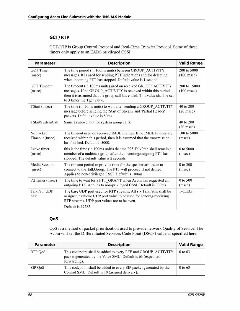
Configuring Acom Line Subracks with the IMS ALS Module
68 025-9529P
GCT/RTP
GCT/RTP is Group Control Protocol and Real-Time Transfer Protocol. Some of these timers only apply to an EADS privileged CSSI.
QoS
QoS is a method of packet prioritization used to provide network Quality of Service. The Acom will set the Differentiated Services Code Point (DSCP) value as specified here.
Parameter Description Valid Range
GCT Timer (msec)
The time period (in 100ms units) between GROUP_ACTIVITY messages. It is used for sending PTT indications and for detecting when incoming PTT has stopped. Default value is 1 second.
200 to 5000 (100 msec)
GCT Timeout (msec)
The timeout (in 100ms units) used on received GROUP_ACTIVITY messages. If no GROUP_ACTIVITY is received within this period then it is assumed that the group call has ended. This value shall be set to 3 times the Tgct value.
200 to 15000 (100 msec)
TStart (msec) The time (in 20ms units) to wait after sending a GROUP_ACTIVITY message before sending the 'Start of Stream' and 'Partial Header' packets. Default value is 80ms.
40 to 200(20 msec)
TStartSystemCall Same as above, but for system group calls. 40 to 200(20 msec)
No Packet Timeout (msec)
The timeout used on received IMBE Frames. If no IMBE Frames are received within this period, then it is assumed that the transmission has finished. Default is 5000.
100 to 5000 (msec)
Leave timer (msec)
this is the time (in 100ms units) that the P25 TalkPath shall remain a member of a multicast group after the incoming/outgoing PTT has stopped. The default value is 2 seconds.
0 to 5000 (msec)
Media Session (msec)
The timeout period to provide time for the speaker arbitrator to connect to the TalkGroup. The PTT will proceed if not denied. Applies to non-privileged CSSI. Default is 100ms
0 to 300 (msec)
Ptt Timer (msec) The time to wait for a PTT_GRANT when Acom has requested an outgoing PTT. Applies to non-privileged CSSI. Default is 300ms
0 to 500 (msec)
TalkPath UDP base
The base UDP port used for RTP streams. All six TalkPaths shall be assigned a unique UDP port value to be used for sending/receiving RTP streams. UDP port values are to be even.
Default is 49282.
1-65535
Parameter Description Valid Range
RTP QoS This codepoint shall be added to every RTP and GROUP_ACTIVITY packet generated by the Voice SMU. Default is 63 (expedited forwarding).
0 to 63
SIP QoS This codepoint shall be added to every SIP packet generated by the Control SMU. Default is 10 (assured delivery).
0 to 63
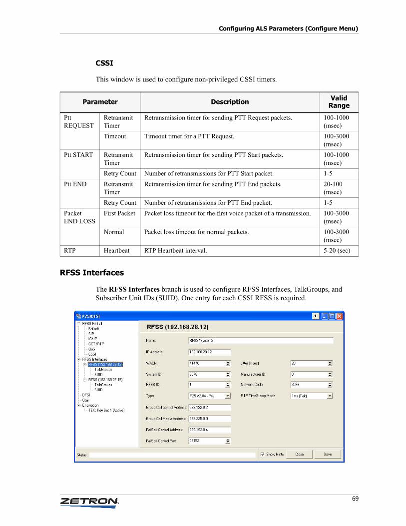
69
Configuring ALS Parameters (Configure Menu)
CSSI
This window is used to configure non-privileged CSSI timers.
RFSS Interfaces
The RFSS Interfaces branch is used to configure RFSS Interfaces, TalkGroups, and Subscriber Unit IDs (SUID). One entry for each CSSI RFSS is required.
Parameter Description Valid Range
Ptt REQUEST
Retransmit Timer
Retransmission timer for sending PTT Request packets. 100-1000 (msec)
Timeout Timeout timer for a PTT Request. 100-3000 (msec)
Ptt START Retransmit Timer
Retransmission timer for sending PTT Start packets. 100-1000 (msec)
Retry Count Number of retransmissions for PTT Start packet. 1-5
Ptt END Retransmit Timer
Retransmission timer for sending PTT End packets. 20-100 (msec)
Retry Count Number of retransmissions for PTT End packet. 1-5
Packet END LOSS
First Packet Packet loss timeout for the first voice packet of a transmission. 100-3000 (msec)
Normal Packet loss timeout for normal packets. 100-3000 (msec)
RTP Heartbeat RTP Heartbeat interval. 5-20 (sec)
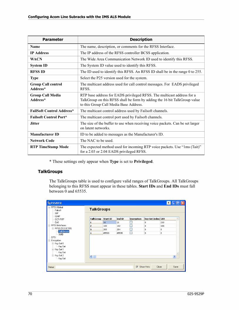
Configuring Acom Line Subracks with the IMS ALS Module
70 025-9529P
* These settings only appear when Type is set to Privileged.
TalkGroups
The TalkGroups table is used to configure valid ranges of TalkGroups. All TalkGroups belonging to this RFSS must appear in these tables. Start IDs and End IDs must fall between 0 and 65535.
Parameter Description
Name The name, description, or comments for the RFSS Interface.
IP Address The IP address of the RFSS controller BCSS application.
WACN The Wide Area Communication Network ID used to identify this RFSS.
System ID The System ID value used to identify this RFSS.
RFSS ID The ID used to identify this RFSS. An RFSS ID shall be in the range 0 to 255.
Type Select the P25 version used for the system.
Group Call control Address*
The multicast address used for call control messages. For EADS privileged RFSS.
Group Call Media Address*
RTP base address for EADS privileged RFSS. The multicast address for a TalkGroup on this RFSS shall be form by adding the 16 bit TalkGroup value to this Group Call Media Base Address.
FailSoft Control Address* The multicast control address used by Failsoft channels.
Failsoft Control Port* The multicast control port used by Failsoft channels.
Jitter The size of the buffer to use when receiving voice packets. Can be set larger on latent networks.
Manufacturer ID ID to be added to messages as the Manufacturer's ID.
Network Code The NAC to be used.
RTP TimeStamp Mode The expected method used for incoming RTP voice packets. Use “1ms (Tait)” for a 2.03 or 2.04 EADS privileged RFSS.
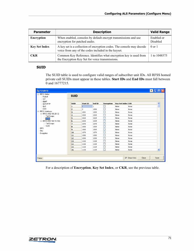
71
Configuring ALS Parameters (Configure Menu)
SUID
The SUID table is used to configure valid ranges of subscriber unit IDs. All RFSS homed private call SUIDs must appear in these tables. Start IDs and End IDs must fall between 0 and 16777215.
For a description of Encryption, Key Set Index, or CKR, see the previous table.
Parameter Description Valid Range
Encryption When enabled, consoles by default encrypt transmissions and use encryption for patched audio.
Enabled or Disabled
Key Set Index A key set is a collection of encryption codes. The console may decode voice from any of the codes included in the keyset.
0 or 1
CKR Common Key Reference. Identifies what encryption key is used from the Encryption Key Set for voice transmissions.
1 to 1048575
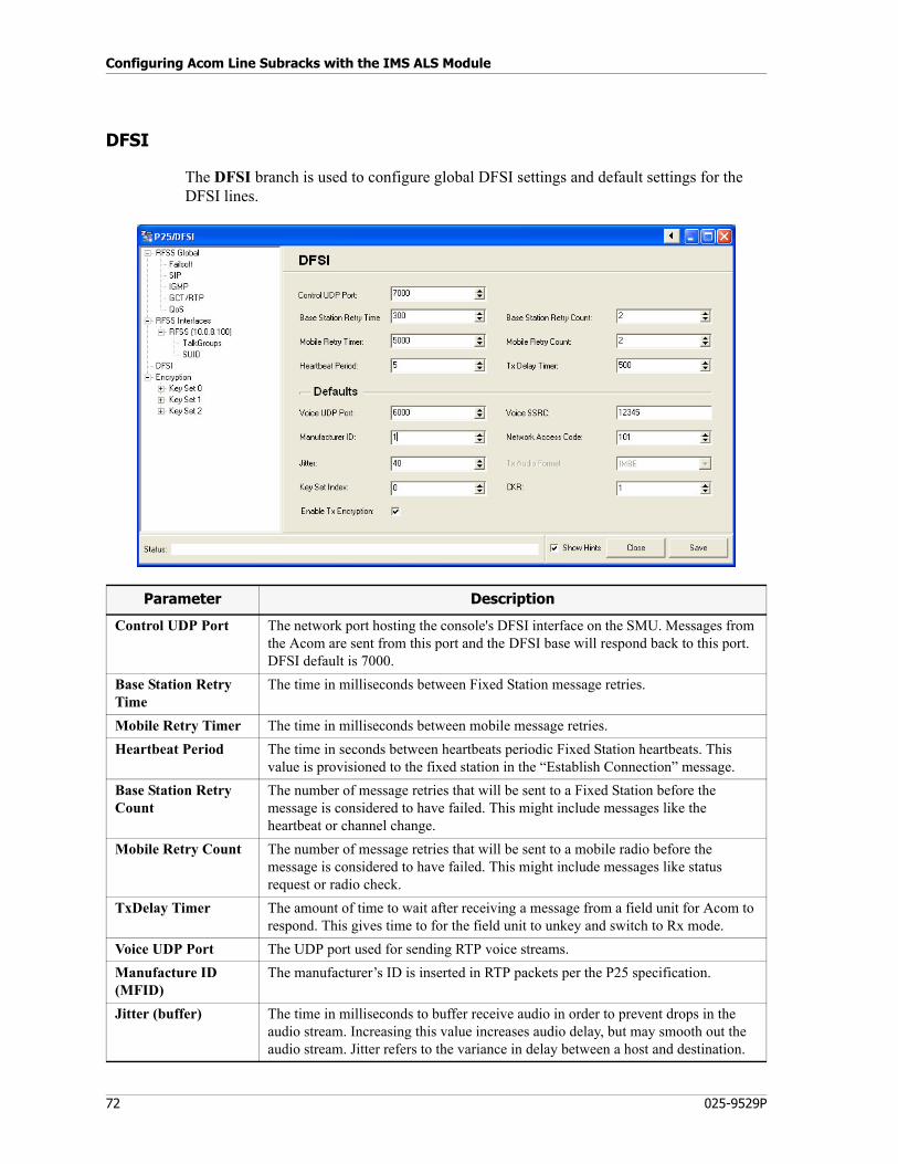
Configuring Acom Line Subracks with the IMS ALS Module
72 025-9529P
DFSI
The DFSI branch is used to configure global DFSI settings and default settings for the DFSI lines.
Parameter Description
Control UDP Port The network port hosting the console's DFSI interface on the SMU. Messages from the Acom are sent from this port and the DFSI base will respond back to this port. DFSI default is 7000.
Base Station Retry Time
The time in milliseconds between Fixed Station message retries.
Mobile Retry Timer The time in milliseconds between mobile message retries.
Heartbeat Period The time in seconds between heartbeats periodic Fixed Station heartbeats. This value is provisioned to the fixed station in the “Establish Connection” message.
Base Station Retry Count
The number of message retries that will be sent to a Fixed Station before the message is considered to have failed. This might include messages like the heartbeat or channel change.
Mobile Retry Count The number of message retries that will be sent to a mobile radio before the message is considered to have failed. This might include messages like status request or radio check.
TxDelay Timer The amount of time to wait after receiving a message from a field unit for Acom to respond. This gives time to for the field unit to unkey and switch to Rx mode.
Voice UDP Port The UDP port used for sending RTP voice streams.
Manufacture ID (MFID)
The manufacturer’s ID is inserted in RTP packets per the P25 specification.
Jitter (buffer) The time in milliseconds to buffer receive audio in order to prevent drops in the audio stream. Increasing this value increases audio delay, but may smooth out the audio stream. Jitter refers to the variance in delay between a host and destination.
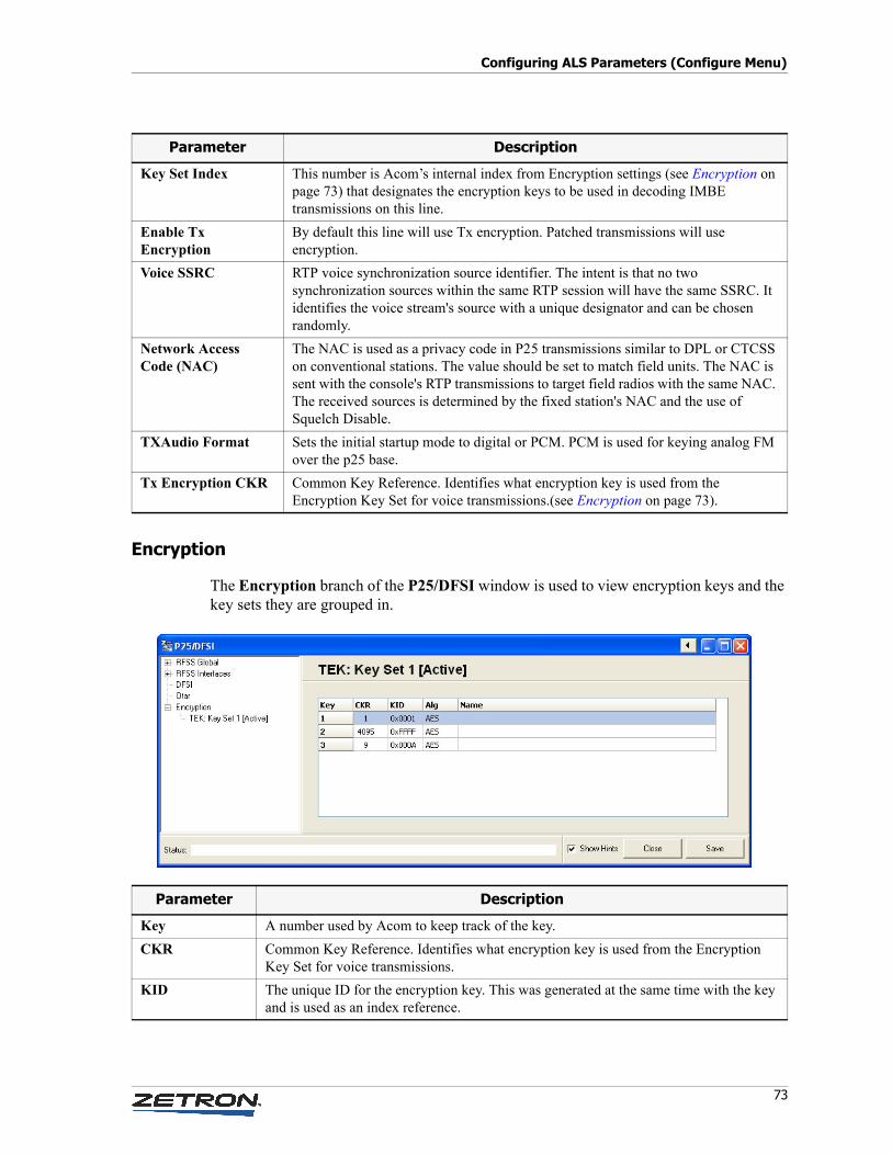
73
Configuring ALS Parameters (Configure Menu)
Encryption
The Encryption branch of the P25/DFSI window is used to view encryption keys and the key sets they are grouped in.
Key Set Index This number is Acom’s internal index from Encryption settings (see Encryption on page 73) that designates the encryption keys to be used in decoding IMBE transmissions on this line.
Enable Tx Encryption
By default this line will use Tx encryption. Patched transmissions will use encryption.
Voice SSRC RTP voice synchronization source identifier. The intent is that no two synchronization sources within the same RTP session will have the same SSRC. It identifies the voice stream's source with a unique designator and can be chosen randomly.
Network Access Code (NAC)
The NAC is used as a privacy code in P25 transmissions similar to DPL or CTCSS on conventional stations. The value should be set to match field units. The NAC is sent with the console's RTP transmissions to target field radios with the same NAC. The received sources is determined by the fixed station's NAC and the use of Squelch Disable.
TXAudio Format Sets the initial startup mode to digital or PCM. PCM is used for keying analog FM over the p25 base.
Tx Encryption CKR Common Key Reference. Identifies what encryption key is used from the Encryption Key Set for voice transmissions.(see Encryption on page 73).
Parameter Description
Parameter Description
Key A number used by Acom to keep track of the key.
CKR Common Key Reference. Identifies what encryption key is used from the Encryption Key Set for voice transmissions.
KID The unique ID for the encryption key. This was generated at the same time with the key and is used as an index reference.
Configuring Acom Line Subracks with the IMS ALS Module
74 025-9529P
These fields are for display only in IMS ALS. The actual key and related information is entered by a key loader device as described in the following procedure.
♦ To load key metadata into the MCU
This procedure describes how to load key metadata using a Motorola KVL-3000 keyloader and TAIT 9000 adapter.
1. Use IMS ALS to configure the MCU serial port for keyloading:
a. Right-click the MCU4 and select Serial Port, Port 1. (You can use Port 2 instead, but you will need a serial convertor to convert Port 2 from RS-422 to RS-232).
b. Set the connection to Keyfill, 8, N, 1, 19200, no handshaking.
c. Click File, Update to Rack.
2. Connect the Motorola KVL-3000 keyloader to the TAIT 9000 adapter.
3. Connect the TAIT 9000 adapter to the MCU debug port (the top DB-9 port) using a straight-through, 9-pin serial patch cable. (Or the lower DB-9 port, if using an RS-422 to RS-232 adapter.)
4. Turn on the keyloader.
5. If you want to clear the key metadata in the MCU first:
• Single key:
TARGET | ZERO | KEY | (◄ or ► to select key) | ZERO
• A group of keys:
TARGET | ZERO | GROUP | (◄ or ► to select group) | ZERO
• All keys in the keyloader:
TARGET | ZERO | ALL | YES
6. To load key metadata to the MCU (actual keys are not stored in the MCU):
• Single key:
TARGET | LOAD | KEY | (◄ or ► to select key) | LOAD
• A group of keys:
TARGET | LOAD | GROUP | (◄ or ► to select group) | LOAD
• All keys in the keyloader:
TARGET | LOAD | ALL | YES
7. Use IMS ALS to double-check the key metadata loaded:
Alg The algorithm used for encryption.
Name An informal name for the key.
Parameter Description
Note The MCU only stores the keys' metadata. The keys themselves are stored only in Secure Cryptographic Modules.
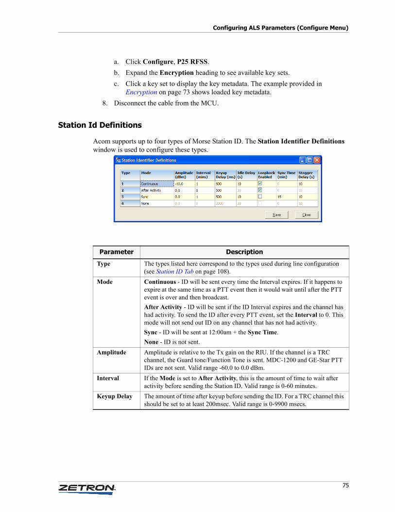
75
Configuring ALS Parameters (Configure Menu)
a. Click Configure, P25 RFSS.
b. Expand the Encryption heading to see available key sets.
c. Click a key set to display the key metadata. The example provided in Encryption on page 73 shows loaded key metadata.
8. Disconnect the cable from the MCU.
Station Id Definitions
Acom supports up to four types of Morse Station ID. The Station Identifier Definitions window is used to configure these types.
Parameter Description
Type The types listed here correspond to the types used during line configuration (see Station ID Tab on page 108).
Mode Continuous - ID will be sent every time the Interval expires. If it happens to expire at the same time as a PTT event then it would wait until after the PTT event is over and then broadcast.
After Activity - ID will be sent if the ID Interval expires and the channel has had activity. To send the ID after every PTT event, set the Interval to 0. This mode will not send out ID on any channel that has not had activity.
Sync - ID will be sent at 12:00am + the Sync Time.
None - ID is not sent.
Amplitude Amplitude is relative to the Tx gain on the RIU. If the channel is a TRC channel, the Guard tone/Function Tone is sent. MDC-1200 and GE-Star PTT IDs are not sent. Valid range -60.0 to 0.0 dBm.
Interval If the Mode is set to After Activity, this is the amount of time to wait after activity before sending the Station ID. Valid range is 0-60 minutes.
Keyup Delay The amount of time after keyup before sending the ID. For a TRC channel this should be set to at least 200msec. Valid range is 0-9900 msecs.
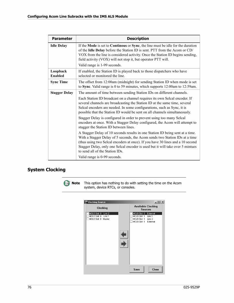
Configuring Acom Line Subracks with the IMS ALS Module
76 025-9529P
System Clocking
Idle Delay If the Mode is set to Continous or Sync, the line must be idle for the duration of the Idle Delay before the Station ID is sent. PTT from the Acom or CD/VOX from the line is considered activity. Once the Station ID begins sending, field activity (VOX) will not stop it, but operator PTT will.
Valid range is 1-99 seconds.
Loopback Enabled
If enabled, the Station ID is played back to those dispatchers who have selected or monitored the line.
Sync Time The offset from 12:00am (midnight) for sending Station ID when mode is set to Sync. Valid range is 0 to 59 minutes, which supports 12:00am to 12:59am.
Stagger Delay The amount of time between sending Station IDs on different channels.
Each Station ID broadcast on a channel requires its own Selcal encoder. If several channels are broadcasting the Station ID at the same time, several Selcal encoders are needed. In some configurations, such as Sync, it is possible that the Station ID would be sent on all channels simultaneously.
Stagger Delay is configured in order to prevent using too many Selcal encoders at once. With a Stagger Delay configured, the Acom will attempt to stagger the Station ID between lines.
A Stagger Delay of 10 seconds results in one Station ID being sent at a time. With a Stagger Delay of 5 seconds, the Acom sends two Station IDs at a time (thus using two Selcal encoders at once). If you have 30 lines and a 10 second Stagger Delay, only one Selcal encoder is used but it will take over 5 mintues to send all of the Station IDs.
Valid range is 0-99 seconds.
Note This option has nothing to do with setting the time on the Acom system, device RTCs, or consoles.
Parameter Description
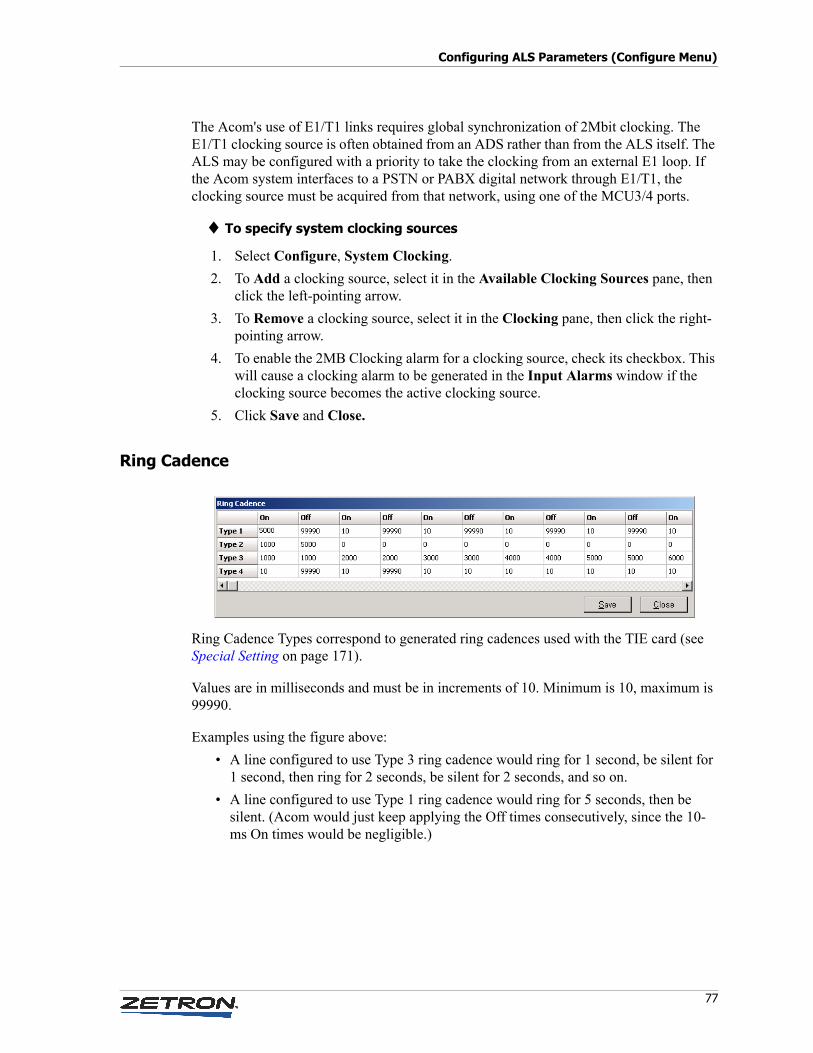
77
Configuring ALS Parameters (Configure Menu)
The Acom's use of E1/T1 links requires global synchronization of 2Mbit clocking. The E1/T1 clocking source is often obtained from an ADS rather than from the ALS itself. The ALS may be configured with a priority to take the clocking from an external E1 loop. If the Acom system interfaces to a PSTN or PABX digital network through E1/T1, the clocking source must be acquired from that network, using one of the MCU3/4 ports.
♦ To specify system clocking sources
1. Select Configure, System Clocking.
2. To Add a clocking source, select it in the Available Clocking Sources pane, then click the left-pointing arrow.
3. To Remove a clocking source, select it in the Clocking pane, then click the right-pointing arrow.
4. To enable the 2MB Clocking alarm for a clocking source, check its checkbox. This will cause a clocking alarm to be generated in the Input Alarms window if the clocking source becomes the active clocking source.
5. Click Save and Close.
Ring Cadence
Ring Cadence Types correspond to generated ring cadences used with the TIE card (see Special Setting on page 171).
Values are in milliseconds and must be in increments of 10. Minimum is 10, maximum is 99990.
Examples using the figure above:
• A line configured to use Type 3 ring cadence would ring for 1 second, be silent for 1 second, then ring for 2 seconds, be silent for 2 seconds, and so on.
• A line configured to use Type 1 ring cadence would ring for 5 seconds, then be silent. (Acom would just keep applying the Off times consecutively, since the 10-ms On times would be negligible.)
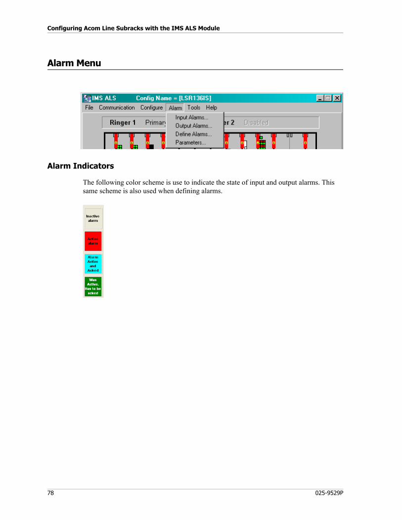
Configuring Acom Line Subracks with the IMS ALS Module
78 025-9529P
Alarm Menu
Alarm Indicators
The following color scheme is use to indicate the state of input and output alarms. This same scheme is also used when defining alarms.
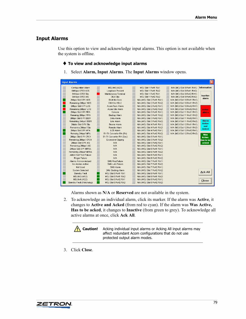
79
Alarm Menu
Input Alarms
Use this option to view and acknowledge input alarms. This option is not available when the system is offline.
♦ To view and acknowledge input alarms
1. Select Alarm, Input Alarms. The Input Alarms window opens.
Alarms shown as N/A or Reserved are not available in the system.
2. To acknowledge an individual alarm, click its marker. If the alarm was Active, it changes to Active and Acked (from red to cyan). If the alarm was Was Active, Has to be acked, it changes to Inactive (from green to grey). To acknowledge all active alarms at once, click Ack All.
3. Click Close.
Caution! Acking individual input alarms or Acking All input alarms may affect redundant Acom configurations that do not use protected output alarm modes.
!
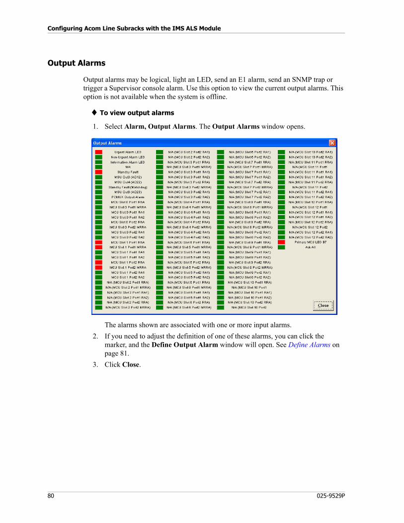
Configuring Acom Line Subracks with the IMS ALS Module
80 025-9529P
Output Alarms
Output alarms may be logical, light an LED, send an E1 alarm, send an SNMP trap or trigger a Supervisor console alarm. Use this option to view the current output alarms. This option is not available when the system is offline.
♦ To view output alarms
1. Select Alarm, Output Alarms. The Output Alarms window opens.
The alarms shown are associated with one or more input alarms.
2. If you need to adjust the definition of one of these alarms, you can click the marker, and the Define Output Alarm window will open. See Define Alarms on page 81.
3. Click Close.
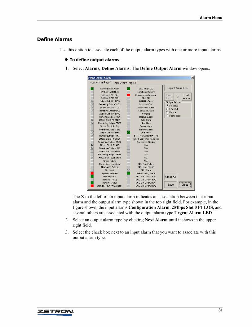
81
Alarm Menu
Define Alarms
Use this option to associate each of the output alarm types with one or more input alarms.
♦ To define output alarms
1. Select Alarms, Define Alarms. The Define Output Alarm window opens.
The X to the left of an input alarm indicates an association between that input alarm and the output alarm type shown in the top right field. For example, in the figure shown, the input alarms Configuration Alarm, 2Mbps Slot 0 P1 LOS, and several others are associated with the output alarm type Urgent Alarm LED.
2. Select an output alarm type by clicking Next Alarm until it shows in the upper right field.
3. Select the check box next to an input alarm that you want to associate with this output alarm type.
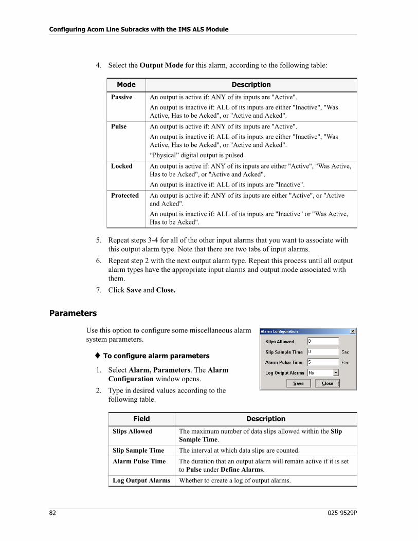
Configuring Acom Line Subracks with the IMS ALS Module
82 025-9529P
4. Select the Output Mode for this alarm, according to the following table:
5. Repeat steps 3-4 for all of the other input alarms that you want to associate with this output alarm type. Note that there are two tabs of input alarms.
6. Repeat step 2 with the next output alarm type. Repeat this process until all output alarm types have the appropriate input alarms and output mode associated with them.
7. Click Save and Close.
Parameters
Use this option to configure some miscellaneous alarm system parameters.
♦ To configure alarm parameters
1. Select Alarm, Parameters. The Alarm Configuration window opens.
2. Type in desired values according to the following table.
Mode Description
Passive An output is active if: ANY of its inputs are "Active".
An output is inactive if: ALL of its inputs are either "Inactive", "Was Active, Has to be Acked", or "Active and Acked".
Pulse An output is active if: ANY of its inputs are "Active".
An output is inactive if: ALL of its inputs are either "Inactive", "Was Active, Has to be Acked", or "Active and Acked".
“Physical” digital output is pulsed.
Locked An output is active if: ANY of its inputs are either "Active", "Was Active, Has to be Acked", or "Active and Acked".
An output is inactive if: ALL of its inputs are "Inactive".
Protected An output is active if: ANY of its inputs are either "Active", or "Active and Acked".
An output is inactive if: ALL of its inputs are "Inactive" or "Was Active, Has to be Acked".
Field Description
Slips Allowed The maximum number of data slips allowed within the Slip Sample Time.
Slip Sample Time The interval at which data slips are counted.
Alarm Pulse Time The duration that an output alarm will remain active if it is set to Pulse under Define Alarms.
Log Output Alarms Whether to create a log of output alarms.
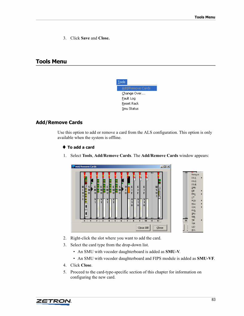
83
Tools Menu
3. Click Save and Close.
Tools Menu
Add/Remove Cards
Use this option to add or remove a card from the ALS configuration. This option is only available when the system is offline.
♦ To add a card
1. Select Tools, Add/Remove Cards. The Add/Remove Cards window appears:
2. Right-click the slot where you want to add the card.
3. Select the card type from the drop-down list.
• An SMU with vocoder daughterboard is added as SMU-V.
• An SMU with vocoder daughterboard and FIPS module is added as SMU-VF.
4. Click Close.
5. Proceed to the card-type-specific section of this chapter for information on configuring the new card.
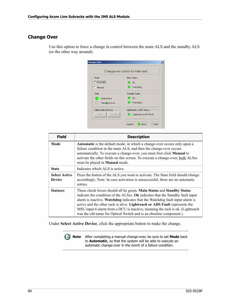
Configuring Acom Line Subracks with the IMS ALS Module
84 025-9529P
Change Over
Use this option to force a change in control between the main ALS and the standby ALS (or the other way around).
Under Select Active Device, click the appropriate button to make the change.
Field Description
Mode Automatic is the default mode, in which a change-over occurs only upon a failure condition in the main ALS, and then the change-over occurs automatically. To execute a change-over, you must first click Manual to activate the other fields on this screen. To execute a change-over, both ALSes must be placed in Manual mode.
State Indicates which ALS is active.
Select ActiveDevice
Press the button of the ALS you want to activate. The State field should change accordingly. Note: In case activation is unsuccessful, there are no automatic retries.
Statuses These check boxes should all be green. Main Status and Standby Status indicate the condition of the ALSes. Ok indicates that the Standby fault input alarm is inactive. Watchdog indicates that the Watchdog fault input alarm is active and the other rack is alive. Lightreach or ADS Fault represents the MSU input 6 alarm from a DCU is inactive, meaning the rack is ok. (Lightreach was the old name for Optical Switch and is an obsolete component.)
Note After completing a manual change-over, be sure to set Mode back to Automatic, so that the system will be able to execute an automatic change-over in the event of a failure condition.
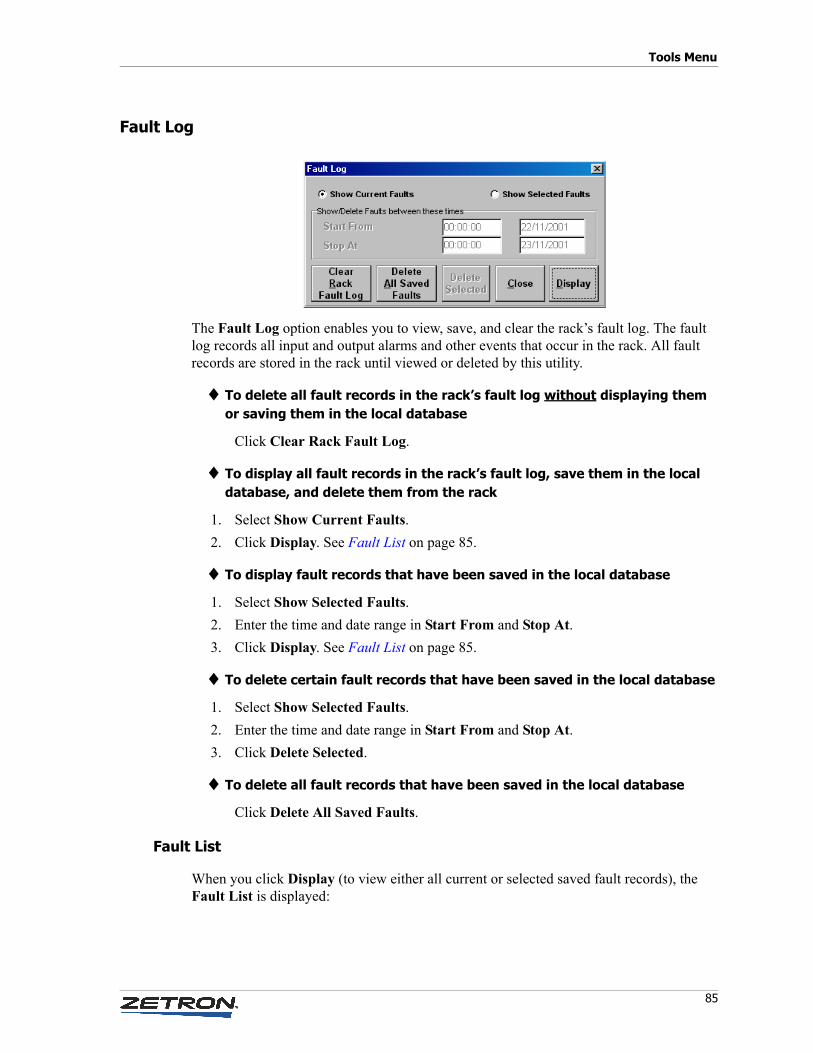
85
Tools Menu
Fault Log
The Fault Log option enables you to view, save, and clear the rack’s fault log. The fault log records all input and output alarms and other events that occur in the rack. All fault records are stored in the rack until viewed or deleted by this utility.
♦ To delete all fault records in the rack’s fault log without displaying them or saving them in the local database
Click Clear Rack Fault Log.
♦ To display all fault records in the rack’s fault log, save them in the local database, and delete them from the rack
1. Select Show Current Faults.
2. Click Display. See Fault List on page 85.
♦ To display fault records that have been saved in the local database
1. Select Show Selected Faults.
2. Enter the time and date range in Start From and Stop At.
3. Click Display. See Fault List on page 85.
♦ To delete certain fault records that have been saved in the local database
1. Select Show Selected Faults.
2. Enter the time and date range in Start From and Stop At.
3. Click Delete Selected.
♦ To delete all fault records that have been saved in the local database
Click Delete All Saved Faults.
Fault List
When you click Display (to view either all current or selected saved fault records), the Fault List is displayed:
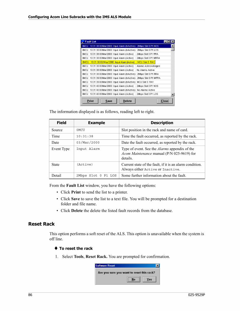
Configuring Acom Line Subracks with the IMS ALS Module
86 025-9529P
The information displayed is as follows, reading left to right.
From the Fault List window, you have the following options:
• Click Print to send the list to a printer.
• Click Save to save the list to a text file. You will be prompted for a destination folder and file name.
• Click Delete the delete the listed fault records from the database.
Reset Rack
This option performs a soft reset of the ALS. This option is unavailable when the system is off line.
♦ To reset the rack
1. Select Tools, Reset Rack. You are prompted for confirmation.
Field Example Description
Source 0MCU Slot position in the rack and name of card.
Time 10:31:38 Time the fault occurred, as reported by the rack.
Date 03/Mar/2000 Date the fault occurred, as reported by the rack.
Event Type Input Alarm Type of event. See the Alarms appendix of the Acom Maintenance manual (P/N 025-9619) for details.
State (Active) Current state of the fault, if it is an alarm condition. Always either Active or Inactive.
Detail 2Mbps Slot 0 P1 LOS Some further information about the fault.
87
Tools Menu
2. When you click Yes, the ALS resets, IMS ALS goes offline, and the main window is cleared.
SMU Status
SMU Status in the Tools menu displays ping and DFSI status as described below.
Ping Result
The Ping Result tab provides a list of all IP addresses that are configured to be “pinged” in order to verify the connectivity of external IP components. The IP addresses are configured in the SMU Extended Parameters (see Extended Card Parameters on page 142).
DFSI
The DFSI tab provides a list of all the DFSI lines defined in the Acom subrack and what their current status is.
Caution! Any configuration changes that have not been updated to the rack will be lost.
!
Column Description
Slot The position of the SMU card that is performing the ping.
Lan Cable The status of the LAN cable connected to this SMU.
IP Address The IP address that is being pinged by the SMU card.
State The current status of the ping (good or bad).
Alarm This indicates if this SMU is actively causing the SMU Ping alarm (in the Acom input alarms) to be set.
Failures This is a count of the number of times the ping has failed.
Column Description
Slot The position of the SMU card that is controlling the DFSI line.
Circuit This is the virtual circuit number that is controlling the DFSI line (DFSI line are required to IMBE vocoders and as such can only be defined on the second DSP of a SMU card. A total of 6 IMBE vocoders are supported).
IP Address The IP address of the DFSI radio.
State Indicates if the connection to the DFSI radio is OK or failed.
Acom Line Number
The Acom Line Number associated with this DFSI interface.
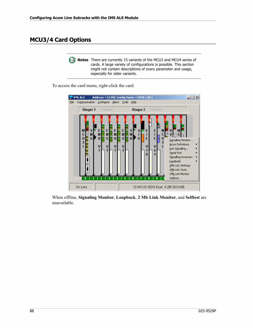
Configuring Acom Line Subracks with the IMS ALS Module
88 025-9529P
MCU3/4 Card Options
To access the card menu, right-click the card.
When offline, Signaling Monitor, Loopback, 2 Mb Link Monitor, and Selftest are unavailable.
Notes There are currently 15 variants of the MCU3 and MCU4 series of cards. A large variety of configurations is possible. This section might not contain descriptions of every parameter and usage, especially for older variants.
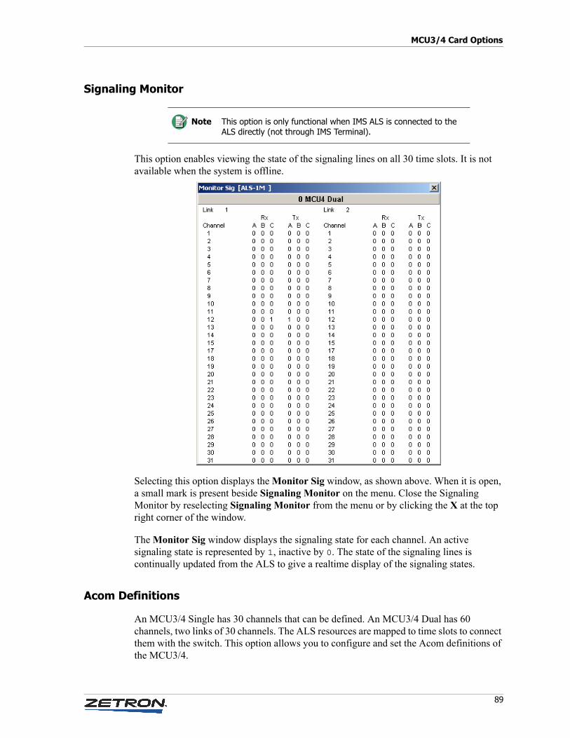
89
MCU3/4 Card Options
Signaling Monitor
This option enables viewing the state of the signaling lines on all 30 time slots. It is not available when the system is offline.
Selecting this option displays the Monitor Sig window, as shown above. When it is open, a small mark is present beside Signaling Monitor on the menu. Close the Signaling Monitor by reselecting Signaling Monitor from the menu or by clicking the X at the top right corner of the window.
The Monitor Sig window displays the signaling state for each channel. An active signaling state is represented by 1, inactive by 0. The state of the signaling lines is continually updated from the ALS to give a realtime display of the signaling states.
Acom Definitions
An MCU3/4 Single has 30 channels that can be defined. An MCU3/4 Dual has 60 channels, two links of 30 channels. The ALS resources are mapped to time slots to connect them with the switch. This option allows you to configure and set the Acom definitions of the MCU3/4.
Note This option is only functional when IMS ALS is connected to the ALS directly (not through IMS Terminal).
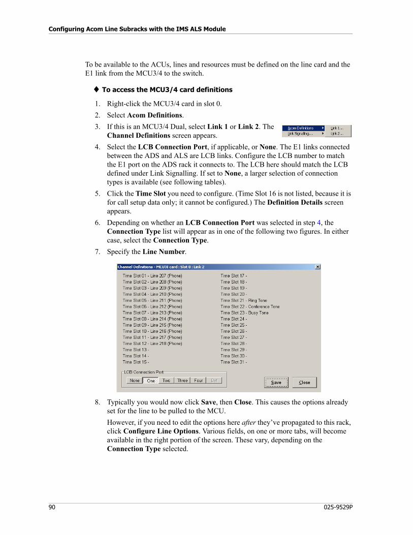
Configuring Acom Line Subracks with the IMS ALS Module
90 025-9529P
To be available to the ACUs, lines and resources must be defined on the line card and the E1 link from the MCU3/4 to the switch.
♦ To access the MCU3/4 card definitions
1. Right-click the MCU3/4 card in slot 0.
2. Select Acom Definitions.
3. If this is an MCU3/4 Dual, select Link 1 or Link 2. The Channel Definitions screen appears.
4. Select the LCB Connection Port, if applicable, or None. The E1 links connected between the ADS and ALS are LCB links. Configure the LCB number to match the E1 port on the ADS rack it connects to. The LCB here should match the LCB defined under Link Signalling. If set to None, a larger selection of connection types is available (see following tables).
5. Click the Time Slot you need to configure. (Time Slot 16 is not listed, because it is for call setup data only; it cannot be configured.) The Definition Details screen appears.
6. Depending on whether an LCB Connection Port was selected in step 4, the Connection Type list will appear as in one of the following two figures. In either case, select the Connection Type.
7. Specify the Line Number.
8. Typically you would now click Save, then Close. This causes the options already set for the line to be pulled to the MCU.
However, if you need to edit the options here after they’ve propagated to this rack, click Configure Line Options. Various fields, on one or more tabs, will become available in the right portion of the screen. These vary, depending on the Connection Type selected.
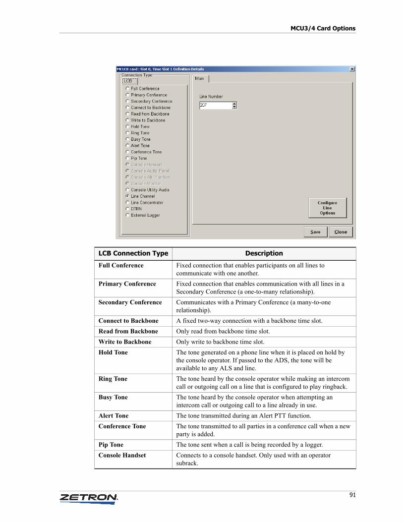
91
MCU3/4 Card Options
LCB Connection Type Description
Full Conference Fixed connection that enables participants on all lines to communicate with one another.
Primary Conference Fixed connection that enables communication with all lines in a Secondary Conference (a one-to-many relationship).
Secondary Conference Communicates with a Primary Conference (a many-to-one relationship).
Connect to Backbone A fixed two-way connection with a backbone time slot.
Read from Backbone Only read from backbone time slot.
Write to Backbone Only write to backbone time slot.
Hold Tone The tone generated on a phone line when it is placed on hold by the console operator. If passed to the ADS, the tone will be available to any ALS and line.
Ring Tone The tone heard by the console operator while making an intercom call or outgoing call on a line that is configured to play ringback.
Busy Tone The tone heard by the console operator when attempting an intercom call or outgoing call to a line already in use.
Alert Tone The tone transmitted during an Alert PTT function.
Conference Tone The tone transmitted to all parties in a conference call when a new party is added.
Pip Tone The tone sent when a call is being recorded by a logger.
Console Handset Connects to a console handset. Only used with an operator subrack.
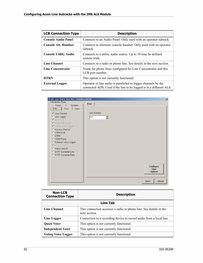
Configuring Acom Line Subracks with the IMS ALS Module
92 025-9529P
Console Audio Panel Connects to an Audio Panel. Only used with an operator subrack.
Console Alt. Handset Connects to alternate console handset. Only used with an operator subrack.
Console Utility Audio Connects to a utility audio source. Up to 10 may be defined system-wide.
Line Channel Connects to a radio or phone line. See details in the next section.
Line Concentrator Trunk for phone lines configured for Line Concentrator and this LCB port number.
DTRN This option is not currently functional.
External Logger Operator or line audio is paralleled to logger channels by the connected ADS. Used if the line to be logged is in a different ALS.
LCB Connection Type Description
Non-LCBConnection Type Description
Line Tab
Line Channel This connection accesses a radio or phone line. See details in the next section.
Line Logger Connection to a recording device to record audio from a local line.
Quasi Voter This option is not currently functional.
Independent Voter This option is not currently functional.
Voting Voice Logger This option is not currently functional.
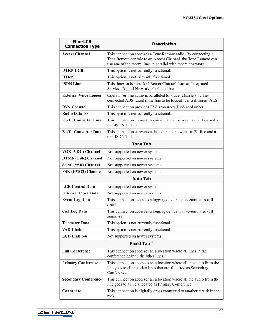
93
MCU3/4 Card Options
Access Channel This connection accesses a Tone Remote radio. By connecting a Tone Remote console to an Access Channel, the Tone Remote can use one of the Acom lines in parallel with Acom operators.
DTRN LCB This option is not currently functional.
DTRN This option is not currently functional.
ISDN Line This timeslot is a trunked Bearer Channel from an Integrated Services Digital Network telephone line.
External Voice Logger Operator or line audio is paralleled to logger channels by the connected ADS. Used if the line to be logged is in a different ALS.
RVA Channel This connection provides RVA resources (RVA card only).
Radio Data I/F This option is not currently functional.
E1/T1 Converter Line This connection converts a voice channel between an E1 line and a non-ISDN T1 line.
E1/T1 Converter Data This connection converts a data channel between an E1 line and a non-ISDN T1 line.
Tone Tab
VOX (VDC) Channel Not supported on newer systems.
DTMF (TSR) Channel Not supported on newer systems.
Selcal (SSR) Channel Not supported on newer systems.
FSK (FMO2) Channel Not supported on newer systems.
Data Tab
LCB Control Data Not supported on newer systems.
External Clock Data Not supported on newer systems.
Event Log Data This connection accesses a logging device that accumulates call detail.
Call Log Data This connection accesses a logging device that accumulates call summary.
Telemetry Data This option is not currently functional.
VAD Chain This option is not currently functional.
LCB Link 1-4 Not supported on newer systems.
Fixed Tab 1
Full Conference This connection accesses an allocation where all lines in the conference hear all the other lines.
Primary Conference This connection accesses an allocation where all the audio from the line goes to all the other lines that are allocated as Secondary Conference.
Secondary Conference This connection accesses an allocation where all the audio from the line goes to a line allocated as Primary Conference.
Connect to This connection is digitally cross connected to another circuit in the rack.
Non-LCBConnection Type Description
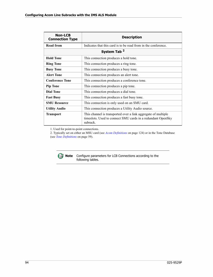
Configuring Acom Line Subracks with the IMS ALS Module
94 025-9529P
Read from Indicates that this card is to be read from in the conference.
System Tab 2
Hold Tone This connection produces a hold tone.
Ring Tone This connection produces a ring tone.
Busy Tone This connection produces a busy tone.
Alert Tone This connection produces an alert tone.
Conference Tone This connection produces a conference tone.
Pip Tone This connection produces a pip tone.
Dial Tone This connection produces a dial tone.
Fast Busy This connection produces a fast busy tone.
SMU Resource This connection is only used on an SMU card.
Utility Audio This connection produces a Utility Audio source.
Transport This channel is transported over a link aggregate of multiple timeslots. Used to connect SMU cards in a redundant OpenSky subrack.
1. Used for point-to-point connections.2. Typically set on either an MSU card (see Acom Definitions on page 124) or in the Tone Database (see Tone Definitions on page 59).
Note Configure parameters for LCB Connections according to the following tables.
Non-LCBConnection Type Description
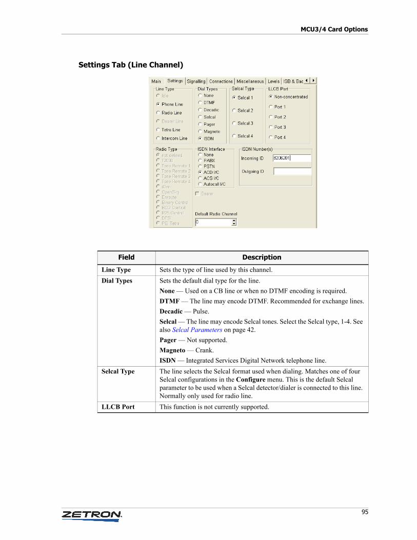
95
MCU3/4 Card Options
Settings Tab (Line Channel)
Field Description
Line Type Sets the type of line used by this channel.
Dial Types Sets the default dial type for the line.
None — Used on a CB line or when no DTMF encoding is required.
DTMF — The line may encode DTMF. Recommended for exchange lines.
Decadic — Pulse.
Selcal — The line may encode Selcal tones. Select the Selcal type, 1-4. See also Selcal Parameters on page 42.
Pager — Not supported.
Magneto — Crank.
ISDN — Integrated Services Digital Network telephone line.
Selcal Type The line selects the Selcal format used when dialing. Matches one of four Selcal configurations in the Configure menu. This is the default Selcal parameter to be used when a Selcal detector/dialer is connected to this line. Normally only used for radio line.
LLCB Port This function is not currently supported.
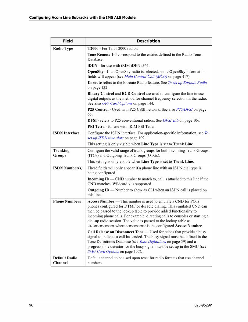
Configuring Acom Line Subracks with the IMS ALS Module
96 025-9529P
Radio Type T2000 - For Tait T2000 radios.
Tone Remote 1-4 correspond to the entries defined in the Radio Tone Database.
iDEN - for use with iRIM iDEN i365.
OpenSky - If an OpenSky radio is selected, some OpenSky information fields will appear (see Main Control Unit (MCU) on page 417).
Enroute refers to the Enroute Radio feature. See To set up Enroute Radio on page 132.
Binary Control and BCD Control are used to configure the line to use digital outputs as the method for channel frequency selection in the radio. See also UIO Card Options on page 144.
P25 Control - Used with P25 CSSI network. See also P25/DFSI on page 65.
DFSI - refers to P25 conventional radios. See DFSI Tab on page 106.
PEI Tetra - for use with iRIM PEI Tetra.
ISDN Interface Configure the ISDN interface. For application-specific information, see To set up ISDN time slots on page 109.
This setting is only visible when Line Type is set to Trunk Line.
Trunking Groups
Configure the valid range of trunk groups for both Incoming Trunk Groups (ITGs) and Outgoing Trunk Groups (OTGs).
This setting is only visible when Line Type is set to Trunk Line.
ISDN Number(s) These fields will only appear if a phone line with an ISDN dial type is being configured.
Incoming ID — CND number to match to, call is attached to this line if the CND matches. Wildcard x is supported.
Outgoing ID — Number to show as CLI when an ISDN call is placed on this line.
Phone Numbers Access Number — This number is used to emulate a CND for POTs phones configured for DTMF or decadic dialing. This emulated CND can then be passed to the lookup table to provide added functionality to incoming phone calls. For example, directing calls to consoles or starting a dial-up radio session. The value is passed to the lookup table as CNDxxxxxxxx where xxxxxxxx is the configured Access Number.
Call Release on Disconnect Tone — Used for telcos that provide a busy signal to indicate a call has ended. The busy signal must be defined in the Tone Definitions Database (see Tone Definitions on page 59) and a progress tone detector for the busy signal must be set up in the SMU (see SMU Card Options on page 137).
Default Radio Channel
Default channel to be used upon reset for radio formats that use channel numbers.
Field Description
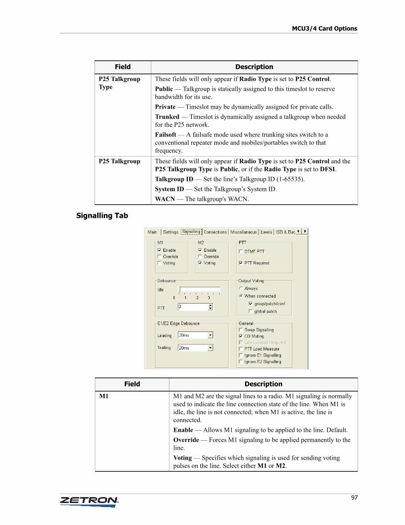
97
MCU3/4 Card Options
Signalling Tab
P25 Talkgroup Type
These fields will only appear if Radio Type is set to P25 Control.
Public — Talkgroup is statically assigned to this timeslot to reserve bandwidth for its use.
Private — Timeslot may be dynamically assigned for private calls.
Trunked — Timeslot is dynamically assigned a talkgroup when needed for the P25 network.
Failsoft — A failsafe mode used where trunking sites switch to a conventional repeater mode and mobiles/portables switch to that frequency.
P25 Talkgroup These fields will only appear if Radio Type is set to P25 Control and the P25 Talkgroup Type is Public, or if the Radio Type is set to DFSI.
Talkgroup ID — Set the line’s Talkgroup ID (1-65535).
System ID — Set the Talkgroup’s System ID.
WACN — The talkgroup's WACN.
Field Description
Field Description
M1 M1 and M2 are the signal lines to a radio. M1 signaling is normally used to indicate the line connection state of the line. When M1 is idle, the line is not connected; when M1 is active, the line is connected.
Enable — Allows M1 signaling to be applied to the line. Default.
Override — Forces M1 signaling to be applied permanently to the line.
Voting — Specifies which signaling is used for sending voting pulses on the line. Select either M1 or M2.
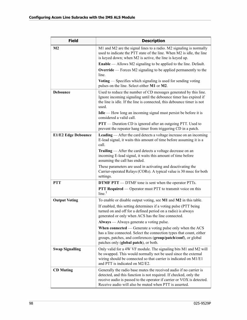
Configuring Acom Line Subracks with the IMS ALS Module
98 025-9529P
M2 M1 and M2 are the signal lines to a radio. M2 signaling is normally used to indicate the PTT state of the line. When M2 is idle, the line is keyed down; when M2 is active, the line is keyed up.
Enable — Allows M2 signaling to be applied to the line. Default.
Override — Forces M2 signaling to be applied permanently to the line.
Voting — Specifies which signaling is used for sending voting pulses on the line. Select either M1 or M2.
Debounce Used to reduce the number of CD messages generated by this line. Ignore incoming signaling until the debounce timer has expired if the line is idle. If the line is connected, this debounce timer is not used.
Idle — How long an incoming signal must persist be before it is considered a valid call.
PTT — Duration CD is ignored after an outgoing PTT. Used to prevent the repeater hang timer from triggering CD in a patch.
E1/E2 Edge Debounce Leading — After the card detects a voltage increase on an incoming E-lead signal, it waits this amount of time before assuming it is a call.
Trailing — After the card detects a voltage decrease on an incoming E-lead signal, it waits this amount of time before assuming the call has ended.
These parameters are used in activating and deactivating the Carrier-operated Relays (CORs). A typical value is 30 msec for both settings.
PTT DTMF PTT — DTMF tone is sent when the operator PTTs.
PTT Required — Operator must PTT to transmit voice on this line.1
Output Voting To enable or disable output voting, see M1 and M2 in this table.
If enabled, this setting determines if a voting pulse (PTT being turned on and off for a defined period on a radio) is always generated or only when ACS has the line connected.
Always — Always generate a voting pulse.
When connected — Generate a voting pulse only when the ACS has a line connected. Select the connection types that count, either groups, patches, and conferences (group/patch/conf), or global patches only (global patch), or both.
Swap Signalling Only valid for a 4W VF module. The signaling bits M1 and M2 will be swapped. This would normally not be used since the external wiring should be connected so that carrier is indicated on M1/E1 and PTT is indicated on M2/E2.
CD Muting Generally the radio base mutes the received audio if no carrier is detected, and this function is not required. If checked, only the receive audio is passed to the operator if carrier or VOX is detected. Receive audio will also be muted when PTT is asserted.
Field Description
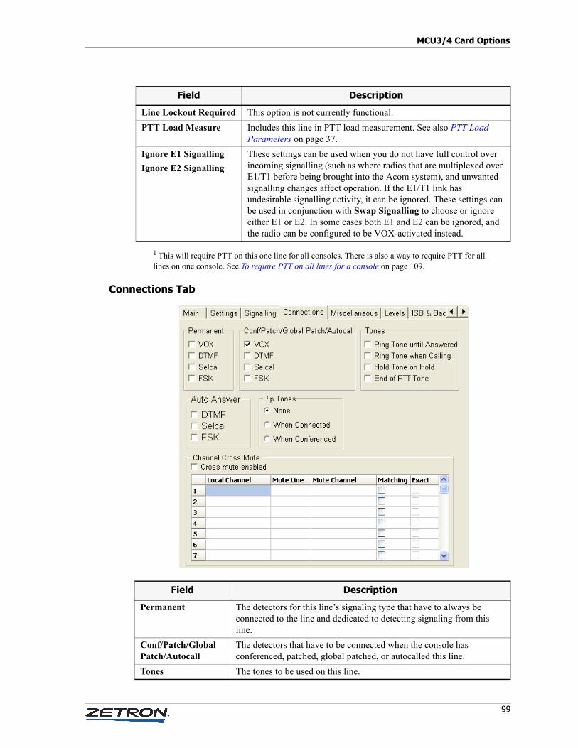
99
MCU3/4 Card Options
1 This will require PTT on this one line for all consoles. There is also a way to require PTT for all lines on one console. See To require PTT on all lines for a console on page 109.
Connections Tab
Line Lockout Required This option is not currently functional.
PTT Load Measure Includes this line in PTT load measurement. See also PTT Load Parameters on page 37.
Ignore E1 Signalling
Ignore E2 Signalling
These settings can be used when you do not have full control over incoming signalling (such as where radios that are multiplexed over E1/T1 before being brought into the Acom system), and unwanted signalling changes affect operation. If the E1/T1 link has undesirable signalling activity, it can be ignored. These settings can be used in conjunction with Swap Signalling to choose or ignore either E1 or E2. In some cases both E1 and E2 can be ignored, and the radio can be configured to be VOX-activated instead.
Field Description
Field Description
Permanent The detectors for this line’s signaling type that have to always be connected to the line and dedicated to detecting signaling from this line.
Conf/Patch/Global Patch/Autocall
The detectors that have to be connected when the console has conferenced, patched, global patched, or autocalled this line.
Tones The tones to be used on this line.
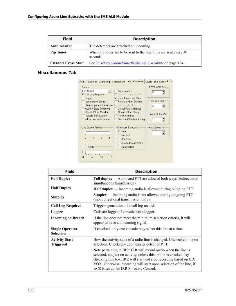
Configuring Acom Line Subracks with the IMS ALS Module
100 025-9529P
Miscellaneous Tab
Auto Answer The detectors are attached on incoming.
Pip Tones When pip tones are to be sent to the line. Pips are sent every 30 seconds.
Channel Cross Mute See To set up channel/line/frequency cross-mute on page 134.
Field Description
Field Description
Full Duplex
Half Duplex
Simplex
Full duplex — Audio and PTT are allowed both ways (bidirectional simultaneous transmission).
Half duplex — Incoming audio is allowed during outgoing PTT.
Simplex — Incoming audio is not allowed during outgoing PTT (monodirectional transmission only).
Call Log Required Triggers generation of a call log record.
Logger Calls are logged if console has a logger.
Incoming on Breach If the line does not meet the minimum selection criteria, it will appear to have an incoming signal.
Single Operator Selection
If checked, only one console may select this line at a time.
Activity State Triggered
How the activity state of a radio line is changed. Unchecked = upon selection. Checked = upon carrier detect or PTT.
Note pertaining to IRR: IRR will record audio when the line is selected, not just on activity, unless this option is checked. By checking this box, IRR will start and stop recording based on CD/VOX. Otherwise, recording will start upon selection of the line, if ACS is set up for IRR Software Control.
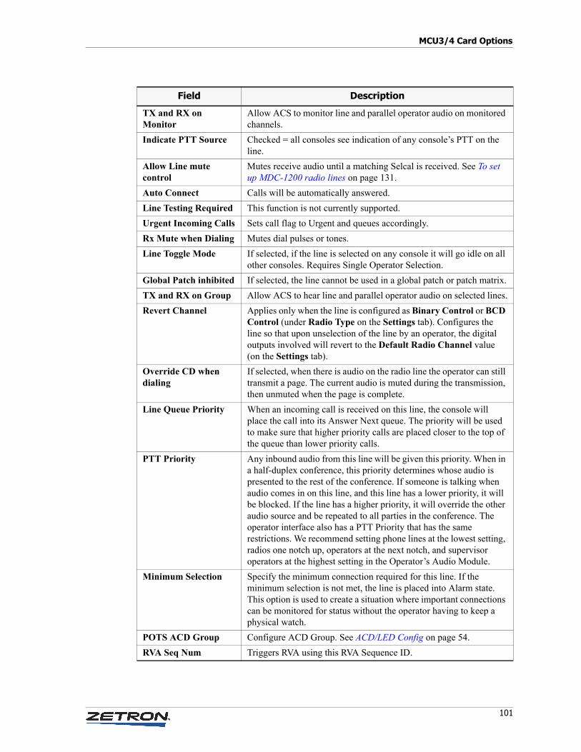
101
MCU3/4 Card Options
TX and RX on Monitor
Allow ACS to monitor line and parallel operator audio on monitored channels.
Indicate PTT Source Checked = all consoles see indication of any console’s PTT on the line.
Allow Line mute control
Mutes receive audio until a matching Selcal is received. See To set up MDC-1200 radio lines on page 131.
Auto Connect Calls will be automatically answered.
Line Testing Required This function is not currently supported.
Urgent Incoming Calls Sets call flag to Urgent and queues accordingly.
Rx Mute when Dialing Mutes dial pulses or tones.
Line Toggle Mode If selected, if the line is selected on any console it will go idle on all other consoles. Requires Single Operator Selection.
Global Patch inhibited If selected, the line cannot be used in a global patch or patch matrix.
TX and RX on Group Allow ACS to hear line and parallel operator audio on selected lines.
Revert Channel Applies only when the line is configured as Binary Control or BCD Control (under Radio Type on the Settings tab). Configures the line so that upon unselection of the line by an operator, the digital outputs involved will revert to the Default Radio Channel value (on the Settings tab).
Override CD when dialing
If selected, when there is audio on the radio line the operator can still transmit a page. The current audio is muted during the transmission, then unmuted when the page is complete.
Line Queue Priority When an incoming call is received on this line, the console will place the call into its Answer Next queue. The priority will be used to make sure that higher priority calls are placed closer to the top of the queue than lower priority calls.
PTT Priority Any inbound audio from this line will be given this priority. When in a half-duplex conference, this priority determines whose audio is presented to the rest of the conference. If someone is talking when audio comes in on this line, and this line has a lower priority, it will be blocked. If the line has a higher priority, it will override the other audio source and be repeated to all parties in the conference. The operator interface also has a PTT Priority that has the same restrictions. We recommend setting phone lines at the lowest setting, radios one notch up, operators at the next notch, and supervisor operators at the highest setting in the Operator’s Audio Module.
Minimum Selection Specify the minimum connection required for this line. If the minimum selection is not met, the line is placed into Alarm state. This option is used to create a situation where important connections can be monitored for status without the operator having to keep a physical watch.
POTS ACD Group Configure ACD Group. See ACD/LED Config on page 54.
RVA Seq Num Triggers RVA using this RVA Sequence ID.
Field Description
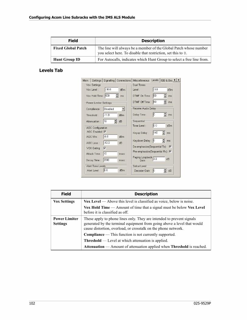
Configuring Acom Line Subracks with the IMS ALS Module
102 025-9529P
Levels Tab
Fixed Global Patch The line will always be a member of the Global Patch whose number you select here. To disable that restriction, set this to 0.
Hunt Group ID For Autocalls, indicates which Hunt Group to select a free line from.
Field Description
Field Description
Vox Settings Vox Level — Above this level is classified as voice, below is noise.
Vox Hold Time — Amount of time that a signal must be below Vox Level before it is classified as off.
Power Limiter Settings
These apply to phone lines only. They are intended to prevent signals generated by the terminal equipment from going above a level that would cause distortion, overload, or crosstalk on the phone network.
Compliance — This function is not currently supported.
Threshold — Level at which attenuation is applied.
Attenuation — Amount of attenuation applied when Threshold is reached.
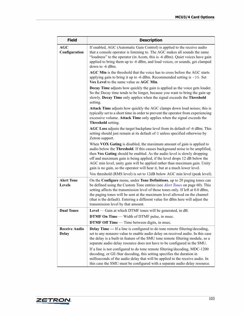
103
MCU3/4 Card Options
AGC Configuration
If enabled, AGC (Automatic Gain Control) is applied to the receive audio that a console operator is listening to. The AGC makes all sounds the same “loudness” to the operator (in Acom, this is -6 dBm). Quiet voices have gain applied to bring them up to -6 dBm, and loud voices, or sounds, get clamped down to -6 dBm.
AGC Min is the threshold that the voice has to cross before the AGC starts applying gain to bring it up to -6 dBm. Recommended setting is -35. Set Vox Level to the same value as AGC Min.
Decay Time adjusts how quickly the gain is applied as the voice gets louder. So the Decay time tends to be longer, because you want to bring the gain up slowly. Decay Time only applies when the signal exceeds the Threshold setting.
Attack Time adjusts how quickly the AGC clamps down loud noises; this is typically set to a short time in order to prevent the operator from experiencing excessive volume. Attack Time only applies when the signal exceeds the Threshold setting.
AGC Loss adjusts the target backplane level from its default of -6 dBm. This setting should just remain at its default of 0 unless specified otherwise by Zetron support.
When VOX Gating is disabled, the maximum amount of gain is applied to audio below the Threshold. If this causes background noise to be amplified, then Vox Gating should be enabled. As the audio level is slowly dropping off and maximum gain is being applied, if the level drops 12 dB below the AGC min level, unity gain will be applied rather than maximum gain. Unity gain is no gain, so the operator will hear it, but at a much lower level.
Vox threshold (RMS level) is set to 12dB below AGC min level (peak level).
Alert Tone Levels
On the Configure menu, under Tone Definitions, up to 20 paging tones can be defined using the Custom Tone entries (see Alert Tones on page 60). This setting affects the transmission level of those tones only. If left at 0.0 dBm, the paging tones will be sent at the maximum level allowed on the channel (that is the default). Entering a different value for dBm here will adjust the transmission level by that amount.
Dual Tones Level — Gain at which DTMF tones will be generated, in dB.
DTMF On Time — Width of DTMF pulse, in msec.
DTMF Off Time — Time between digits, in msec.
Receive Audio Delay
Delay Time — If a line is configured to do tone remote filtering/decoding, set to any nonzero value to enable audio delay on received audio. In this case the delay is a built-in feature of the SMU tone remote filtering module, so a separate audio delay resource does not have to be configured in the SMU.
If a line is not configured to do tone remote filtering/decoding, MDC-1200 decoding, or GE-Star decoding, this setting specifies the duration in milliseconds of the audio delay that will be applied to the receive audio. In this case the SMU must be configured with a separate audio delay resource.
Field Description
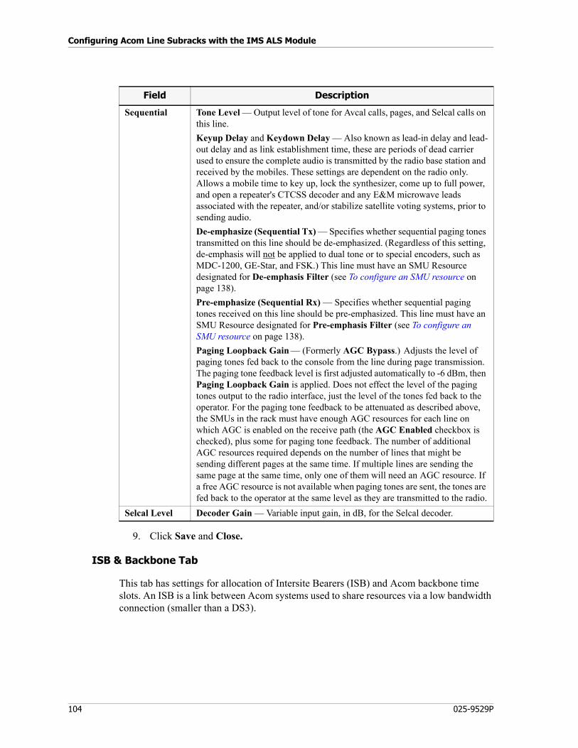
Configuring Acom Line Subracks with the IMS ALS Module
104 025-9529P
9. Click Save and Close.
ISB & Backbone Tab
This tab has settings for allocation of Intersite Bearers (ISB) and Acom backbone time slots. An ISB is a link between Acom systems used to share resources via a low bandwidth connection (smaller than a DS3).
Sequential Tone Level — Output level of tone for Avcal calls, pages, and Selcal calls on this line.
Keyup Delay and Keydown Delay — Also known as lead-in delay and lead-out delay and as link establishment time, these are periods of dead carrier used to ensure the complete audio is transmitted by the radio base station and received by the mobiles. These settings are dependent on the radio only. Allows a mobile time to key up, lock the synthesizer, come up to full power, and open a repeater's CTCSS decoder and any E&M microwave leads associated with the repeater, and/or stabilize satellite voting systems, prior to sending audio.
De-emphasize (Sequential Tx) — Specifies whether sequential paging tones transmitted on this line should be de-emphasized. (Regardless of this setting, de-emphasis will not be applied to dual tone or to special encoders, such as MDC-1200, GE-Star, and FSK.) This line must have an SMU Resource designated for De-emphasis Filter (see To configure an SMU resource on page 138).
Pre-emphasize (Sequential Rx) — Specifies whether sequential paging tones received on this line should be pre-emphasized. This line must have an SMU Resource designated for Pre-emphasis Filter (see To configure an SMU resource on page 138).
Paging Loopback Gain — (Formerly AGC Bypass.) Adjusts the level of paging tones fed back to the console from the line during page transmission. The paging tone feedback level is first adjusted automatically to -6 dBm, then Paging Loopback Gain is applied. Does not effect the level of the paging tones output to the radio interface, just the level of the tones fed back to the operator. For the paging tone feedback to be attenuated as described above, the SMUs in the rack must have enough AGC resources for each line on which AGC is enabled on the receive path (the AGC Enabled checkbox is checked), plus some for paging tone feedback. The number of additional AGC resources required depends on the number of lines that might be sending different pages at the same time. If multiple lines are sending the same page at the same time, only one of them will need an AGC resource. If a free AGC resource is not available when paging tones are sent, the tones are fed back to the operator at the same level as they are transmitted to the radio.
Selcal Level Decoder Gain — Variable input gain, in dB, for the Selcal decoder.
Field Description
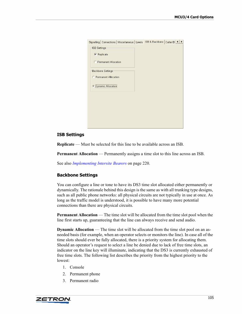
105
MCU3/4 Card Options
ISB Settings
Replicate — Must be selected for this line to be available across an ISB.
Permanent Allocation — Permanently assigns a time slot to this line across an ISB.
See also Implementing Intersite Bearers on page 220.
Backbone Settings
You can configure a line or tone to have its DS3 time slot allocated either permanently or dynamically. The rationale behind this design is the same as with all trunking type designs, such as all public phone networks: all physical circuits are not typically in use at once. As long as the traffic model is understood, it is possible to have many more potential connections than there are physical circuits.
Permanent Allocation — The time slot will be allocated from the time slot pool when the line first starts up, guaranteeing that the line can always receive and send audio.
Dynamic Allocation — The time slot will be allocated from the time slot pool on an as-needed basis (for example, when an operator selects or monitors the line). In case all of the time slots should ever be fully allocated, there is a priority system for allocating them. Should an operator’s request to select a line be denied due to lack of free time slots, an indicator on the line key will illuminate, indicating that the DS3 is currently exhausted of free time slots. The following list describes the priority from the highest priority to the lowest:
1. Console
2. Permanent phone
3. Permanent radio
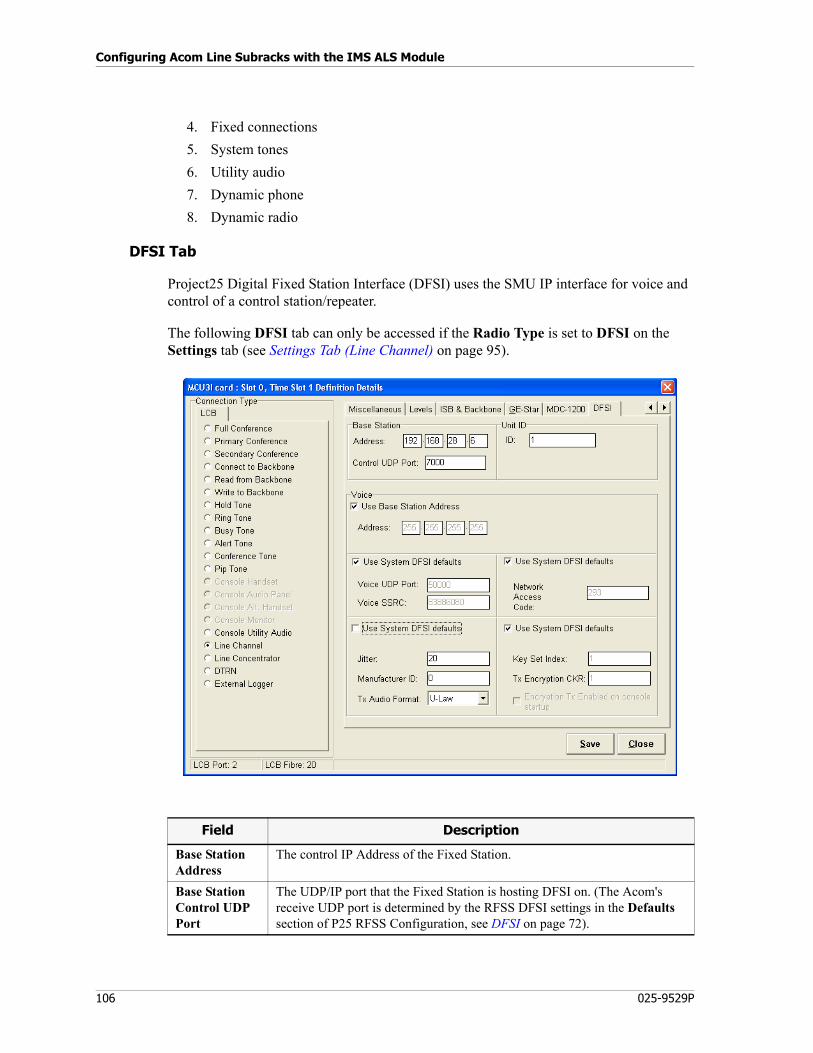
Configuring Acom Line Subracks with the IMS ALS Module
106 025-9529P
4. Fixed connections
5. System tones
6. Utility audio
7. Dynamic phone
8. Dynamic radio
DFSI Tab
Project25 Digital Fixed Station Interface (DFSI) uses the SMU IP interface for voice and control of a control station/repeater.
The following DFSI tab can only be accessed if the Radio Type is set to DFSI on the Settings tab (see Settings Tab (Line Channel) on page 95).
Field Description
Base Station Address
The control IP Address of the Fixed Station.
Base Station Control UDP Port
The UDP/IP port that the Fixed Station is hosting DFSI on. (The Acom's receive UDP port is determined by the RFSS DFSI settings in the Defaults section of P25 RFSS Configuration, see DFSI on page 72).
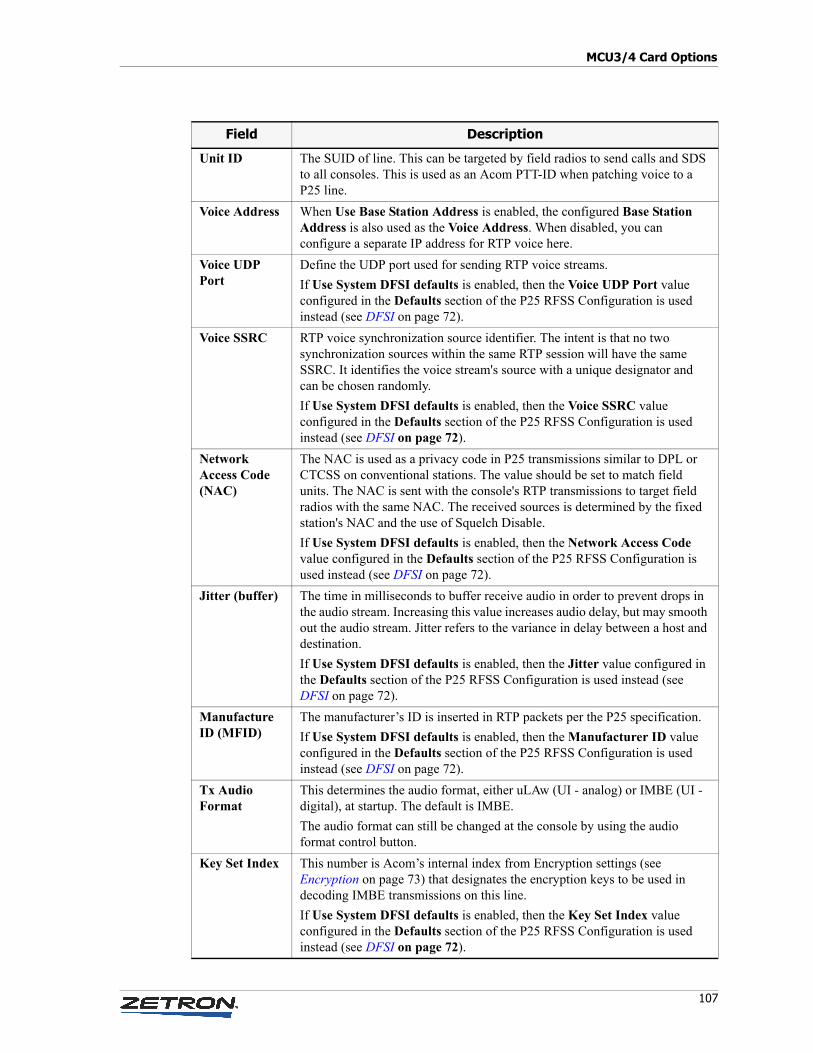
107
MCU3/4 Card Options
Unit ID The SUID of line. This can be targeted by field radios to send calls and SDS to all consoles. This is used as an Acom PTT-ID when patching voice to a P25 line.
Voice Address When Use Base Station Address is enabled, the configured Base Station Address is also used as the Voice Address. When disabled, you can configure a separate IP address for RTP voice here.
Voice UDP Port
Define the UDP port used for sending RTP voice streams.
If Use System DFSI defaults is enabled, then the Voice UDP Port value configured in the Defaults section of the P25 RFSS Configuration is used instead (see DFSI on page 72).
Voice SSRC RTP voice synchronization source identifier. The intent is that no two synchronization sources within the same RTP session will have the same SSRC. It identifies the voice stream's source with a unique designator and can be chosen randomly.
If Use System DFSI defaults is enabled, then the Voice SSRC value configured in the Defaults section of the P25 RFSS Configuration is used instead (see DFSI on page 72).
Network Access Code (NAC)
The NAC is used as a privacy code in P25 transmissions similar to DPL or CTCSS on conventional stations. The value should be set to match field units. The NAC is sent with the console's RTP transmissions to target field radios with the same NAC. The received sources is determined by the fixed station's NAC and the use of Squelch Disable.
If Use System DFSI defaults is enabled, then the Network Access Code value configured in the Defaults section of the P25 RFSS Configuration is used instead (see DFSI on page 72).
Jitter (buffer) The time in milliseconds to buffer receive audio in order to prevent drops in the audio stream. Increasing this value increases audio delay, but may smooth out the audio stream. Jitter refers to the variance in delay between a host and destination.
If Use System DFSI defaults is enabled, then the Jitter value configured in the Defaults section of the P25 RFSS Configuration is used instead (see DFSI on page 72).
Manufacture ID (MFID)
The manufacturer’s ID is inserted in RTP packets per the P25 specification.
If Use System DFSI defaults is enabled, then the Manufacturer ID value configured in the Defaults section of the P25 RFSS Configuration is used instead (see DFSI on page 72).
Tx Audio Format
This determines the audio format, either uLAw (UI - analog) or IMBE (UI - digital), at startup. The default is IMBE.
The audio format can still be changed at the console by using the audio format control button.
Key Set Index This number is Acom’s internal index from Encryption settings (see Encryption on page 73) that designates the encryption keys to be used in decoding IMBE transmissions on this line.
If Use System DFSI defaults is enabled, then the Key Set Index value configured in the Defaults section of the P25 RFSS Configuration is used instead (see DFSI on page 72).
Field Description
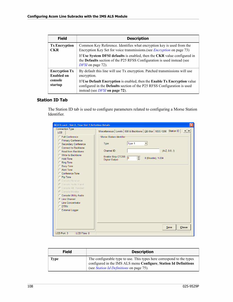
Configuring Acom Line Subracks with the IMS ALS Module
108 025-9529P
Station ID Tab
The Station ID tab is used to configure parameters related to configuring a Morse Station Identifier.
Tx Encryption CKR
Common Key Reference. Identifies what encryption key is used from the Encryption Key Set for voice transmissions.(see Encryption on page 73)
If Use System DFSI defaults is enabled, then the CKR value configured in the Defaults section of the P25 RFSS Configuration is used instead (see DFSI on page 72).
Encryption Tx Enabled on console startup
By default this line will use Tx encryption. Patched transmissions will use encryption.
If Use Default Encryption is enabled, then the Enable Tx Encryption value configured in the Defaults section of the P25 RFSS Configuration is used instead (see DFSI on page 72).
Field Description
Field Description
Type The configurable type to use. This types here correspond to the types configured in the IMS ALS menu Configure, Station Id Definitions (see Station Id Definitions on page 75).
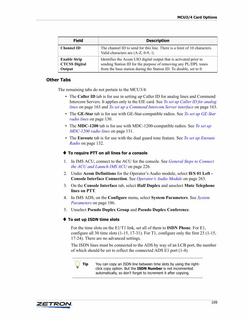
109
MCU3/4 Card Options
Other Tabs
The remaining tabs do not pertain to the MCU3/4:
• The Caller ID tab is for use in setting up Caller ID for analog lines and Commend Intercom Servers. It applies only to the EIE card. See To set up Caller ID for analog lines on page 163 and To set up a Commend Intercom Server interface on page 163.
• The GE-Star tab is for use with GE-Star-compatible radios. See To set up GE-Star radio lines on page 130.
• The MDC-1200 tab is for use with MDC-1200-compatible radios. See To set up MDC-1200 radio lines on page 131.
• The Enroute tab is for use with the dual guard tone feature. See To set up Enroute Radio on page 132.
♦ To require PTT on all lines for a console
1. In IMS ACU, connect to the ACU for the console. See General Steps to Connect the ACU and Launch IMS ACU on page 226.
2. Under Acom Definitions for the Operator’s Audio module, select H/S 01 Left - Console Interface Connection. See Operator’s Audio Module on page 263.
3. On the Console Interface tab, select Half Duplex and unselect Mute Telephone lines on PTT.
4. In IMS ADS, on the Configure menu, select System Parameters. See System Parameters on page 186.
5. Unselect Pseudo Duplex Group and Pseudo Duplex Conference.
♦ To set up ISDN time slots
For the time slots on the E1/T1 link, set all of them to ISDN Phone. For E1, configure all 30 time slots (1-15, 17-31). For T1, configure only the first 23 (1-15, 17-24). There are no advanced settings.
The ISDN lines must be connected to the ADS by way of an LCB port, the number of which should be set to reflect the connected ADS E1 port (1-4).
Channel ID The channel ID to send for this line. There is a limit of 10 characters. Valid characters are (A-Z, 0-9, /).
Enable Strip CTCSS Digital Output
Identifies the Acom UIO digital output that is activated prior to sending Station ID for the purpose of removing any PL/DPL tones from the base station during the Station ID. To disable, set to 0.
Field Description
Tip You can copy an ISDN line between time slots by using the right-click copy option. But the ISDN Number is not incremented automatically, so don’t forget to increment it after copying.
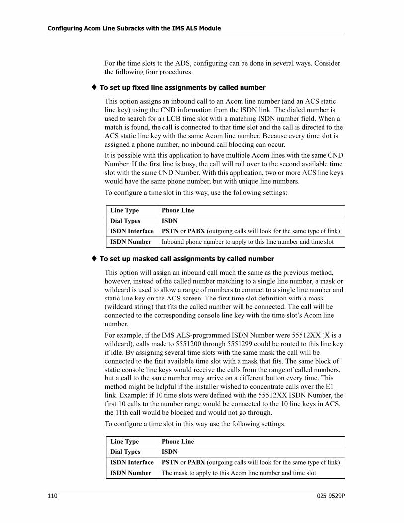
Configuring Acom Line Subracks with the IMS ALS Module
110 025-9529P
For the time slots to the ADS, configuring can be done in several ways. Consider the following four procedures.
♦ To set up fixed line assignments by called number
This option assigns an inbound call to an Acom line number (and an ACS static line key) using the CND information from the ISDN link. The dialed number is used to search for an LCB time slot with a matching ISDN number field. When a match is found, the call is connected to that time slot and the call is directed to the ACS static line key with the same Acom line number. Because every time slot is assigned a phone number, no inbound call blocking can occur.
It is possible with this application to have multiple Acom lines with the same CND Number. If the first line is busy, the call will roll over to the second available time slot with the same CND Number. With this application, two or more ACS line keys would have the same phone number, but with unique line numbers.
To configure a time slot in this way, use the following settings:
♦ To set up masked call assignments by called number
This option will assign an inbound call much the same as the previous method, however, instead of the called number matching to a single line number, a mask or wildcard is used to allow a range of numbers to connect to a single line number and static line key on the ACS screen. The first time slot definition with a mask (wildcard string) that fits the called number will be connected. The call will be connected to the corresponding console line key with the time slot’s Acom line number.
For example, if the IMS ALS-programmed ISDN Number were 55512XX (X is a wildcard), calls made to 5551200 through 5551299 could be routed to this line key if idle. By assigning several time slots with the same mask the call will be connected to the first available time slot with a mask that fits. The same block of static console line keys would receive the calls from the range of called numbers, but a call to the same number may arrive on a different button every time. This method might be helpful if the installer wished to concentrate calls over the E1 link. Example: if 10 time slots were defined with the 55512XX ISDN Number, the first 10 calls to the number range would be connected to the 10 line keys in ACS, the 11th call would be blocked and would not go through.
To configure a time slot in this way use the following settings:
Line Type Phone Line
Dial Types ISDN
ISDN Interface PSTN or PABX (outgoing calls will look for the same type of link)
ISDN Number Inbound phone number to apply to this line number and time slot
Line Type Phone Line
Dial Types ISDN
ISDN Interface PSTN or PABX (outgoing calls will look for the same type of link)
ISDN Number The mask to apply to this Acom line number and time slot
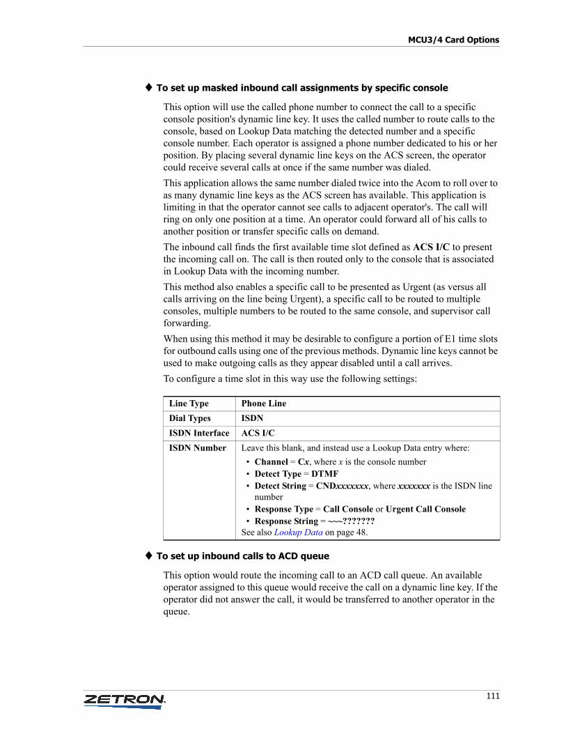
111
MCU3/4 Card Options
♦ To set up masked inbound call assignments by specific console
This option will use the called phone number to connect the call to a specific console position's dynamic line key. It uses the called number to route calls to the console, based on Lookup Data matching the detected number and a specific console number. Each operator is assigned a phone number dedicated to his or her position. By placing several dynamic line keys on the ACS screen, the operator could receive several calls at once if the same number was dialed.
This application allows the same number dialed twice into the Acom to roll over to as many dynamic line keys as the ACS screen has available. This application is limiting in that the operator cannot see calls to adjacent operator's. The call will ring on only one position at a time. An operator could forward all of his calls to another position or transfer specific calls on demand.
The inbound call finds the first available time slot defined as ACS I/C to present the incoming call on. The call is then routed only to the console that is associated in Lookup Data with the incoming number.
This method also enables a specific call to be presented as Urgent (as versus all calls arriving on the line being Urgent), a specific call to be routed to multiple consoles, multiple numbers to be routed to the same console, and supervisor call forwarding.
When using this method it may be desirable to configure a portion of E1 time slots for outbound calls using one of the previous methods. Dynamic line keys cannot be used to make outgoing calls as they appear disabled until a call arrives.
To configure a time slot in this way use the following settings:
♦ To set up inbound calls to ACD queue
This option would route the incoming call to an ACD call queue. An available operator assigned to this queue would receive the call on a dynamic line key. If the operator did not answer the call, it would be transferred to another operator in the queue.
Line Type Phone Line
Dial Types ISDN
ISDN Interface ACS I/C
ISDN Number Leave this blank, and instead use a Lookup Data entry where:
• Channel = Cx, where x is the console number• Detect Type = DTMF• Detect String = CNDxxxxxxx, where xxxxxxx is the ISDN line
number• Response Type = Call Console or Urgent Call Console• Response String = ~~~???????
See also Lookup Data on page 48.
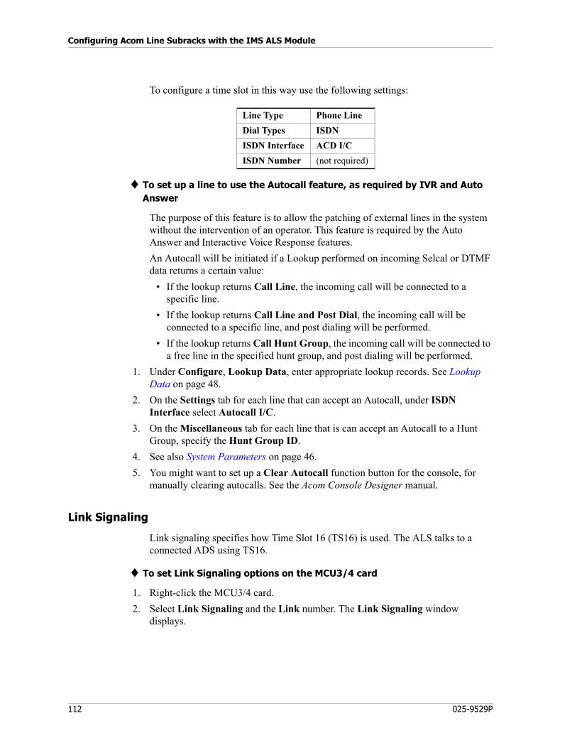
Configuring Acom Line Subracks with the IMS ALS Module
112 025-9529P
To configure a time slot in this way use the following settings:
♦ To set up a line to use the Autocall feature, as required by IVR and Auto Answer
The purpose of this feature is to allow the patching of external lines in the system without the intervention of an operator. This feature is required by the Auto Answer and Interactive Voice Response features.
An Autocall will be initiated if a Lookup performed on incoming Selcal or DTMF data returns a certain value:
• If the lookup returns Call Line, the incoming call will be connected to a specific line.
• If the lookup returns Call Line and Post Dial, the incoming call will be connected to a specific line, and post dialing will be performed.
• If the lookup returns Call Hunt Group, the incoming call will be connected to a free line in the specified hunt group, and post dialing will be performed.
1. Under Configure, Lookup Data, enter appropriate lookup records. See Lookup Data on page 48.
2. On the Settings tab for each line that can accept an Autocall, under ISDN Interface select Autocall I/C.
3. On the Miscellaneous tab for each line that is can accept an Autocall to a Hunt Group, specify the Hunt Group ID.
4. See also System Parameters on page 46.
5. You might want to set up a Clear Autocall function button for the console, for manually clearing autocalls. See the Acom Console Designer manual.
Link Signaling
Link signaling specifies how Time Slot 16 (TS16) is used. The ALS talks to a connected ADS using TS16.
♦ To set Link Signaling options on the MCU3/4 card
1. Right-click the MCU3/4 card.
2. Select Link Signaling and the Link number. The Link Signaling window displays.
Line Type Phone Line
Dial Types ISDN
ISDN Interface ACD I/C
ISDN Number (not required)
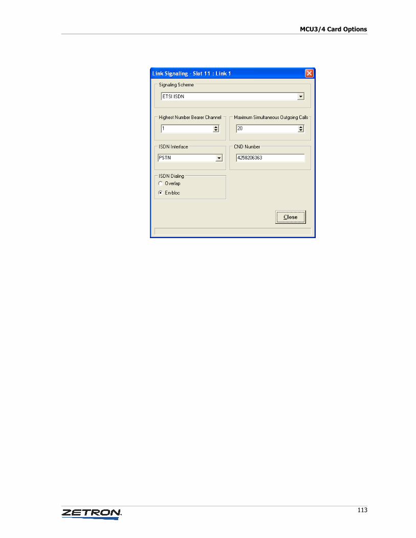
113
MCU3/4 Card Options
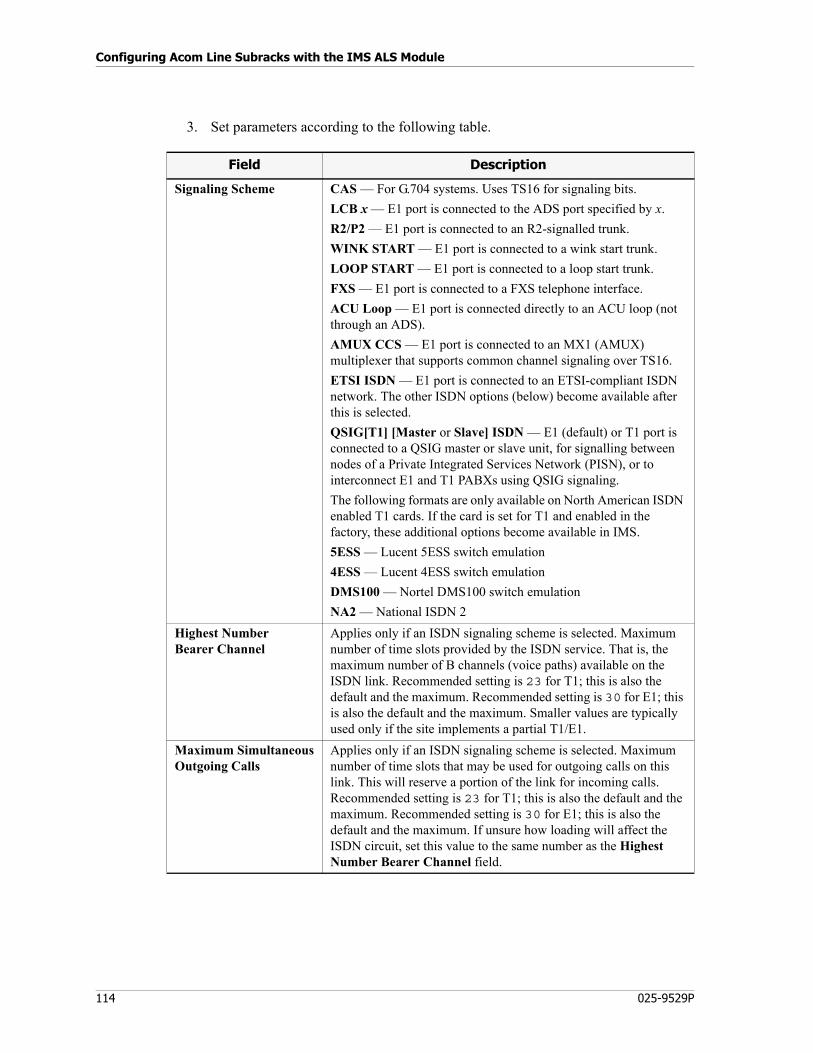
Configuring Acom Line Subracks with the IMS ALS Module
114 025-9529P
3. Set parameters according to the following table.
Field Description
Signaling Scheme CAS — For G.704 systems. Uses TS16 for signaling bits.
LCB x — E1 port is connected to the ADS port specified by x.
R2/P2 — E1 port is connected to an R2-signalled trunk.
WINK START — E1 port is connected to a wink start trunk.
LOOP START — E1 port is connected to a loop start trunk.
FXS — E1 port is connected to a FXS telephone interface.
ACU Loop — E1 port is connected directly to an ACU loop (not through an ADS).
AMUX CCS — E1 port is connected to an MX1 (AMUX) multiplexer that supports common channel signaling over TS16.
ETSI ISDN — E1 port is connected to an ETSI-compliant ISDN network. The other ISDN options (below) become available after this is selected.
QSIG[T1] [Master or Slave] ISDN — E1 (default) or T1 port is connected to a QSIG master or slave unit, for signalling between nodes of a Private Integrated Services Network (PISN), or to interconnect E1 and T1 PABXs using QSIG signaling.
The following formats are only available on North American ISDN enabled T1 cards. If the card is set for T1 and enabled in the factory, these additional options become available in IMS.
5ESS — Lucent 5ESS switch emulation
4ESS — Lucent 4ESS switch emulation
DMS100 — Nortel DMS100 switch emulation
NA2 — National ISDN 2
Highest NumberBearer Channel
Applies only if an ISDN signaling scheme is selected. Maximum number of time slots provided by the ISDN service. That is, the maximum number of B channels (voice paths) available on the ISDN link. Recommended setting is 23 for T1; this is also the default and the maximum. Recommended setting is 30 for E1; this is also the default and the maximum. Smaller values are typically used only if the site implements a partial T1/E1.
Maximum SimultaneousOutgoing Calls
Applies only if an ISDN signaling scheme is selected. Maximum number of time slots that may be used for outgoing calls on this link. This will reserve a portion of the link for incoming calls. Recommended setting is 23 for T1; this is also the default and the maximum. Recommended setting is 30 for E1; this is also the default and the maximum. If unsure how loading will affect the ISDN circuit, set this value to the same number as the Highest Number Bearer Channel field.

115
MCU3/4 Card Options
Serial Port
This function is used to specify the device connection type and configure communication settings for each of the card’s two serial ports.
ISDN Interface Used to route outgoing calls. The ISDN line is configured to find a free trunk on either a PABX trunk, a PSTN trunk, or a configurable trunk (Trunk 1-8). Set this to the same setting used on the Line Channel definitions on the E1 link to the ADS. If all ISDN calls will be going to the same switch, set this to PSTN, and use the same setting when configuring the line channels on the MCU3/4 card. If using Trunk 1-8, the trunk must be configured in the MCU card channel definitions;there must be a configured trunking plan (i.e. using CND/CLI ISDN calls setup).
CND Number The phone number used to represent the Acom switch when making outgoing calls. This number will become the Caller ID of the Acom switch. This number is a default; it may be overridden by a unique CLI in the Acom line’s Acom Definitions.
ACU Type This function is not currently supported.
ACU Loop LR Loop Primary — Port connects to the ADS.
LR Loop Secondary — Port connects to the redundant ADS at the other end of the loop.
ACU Loop Primary — Port connects to the first ACU in the console loop.
ACU Loop Secondary — Port connects to the last ACU in the console loop.
ISDN Dialing Applies only if an ISDN Signaling Scheme is selected.
Overlap — ISDN phone is taken off-hook, dial tone is returned by remote equipment. Dialed digits are sent in individual messages.
En-bloc — ISDN phone is taken off-hook, dial tone is returned by ALS. Dialed digits are sent as part of a Call Setup message.
Field Description
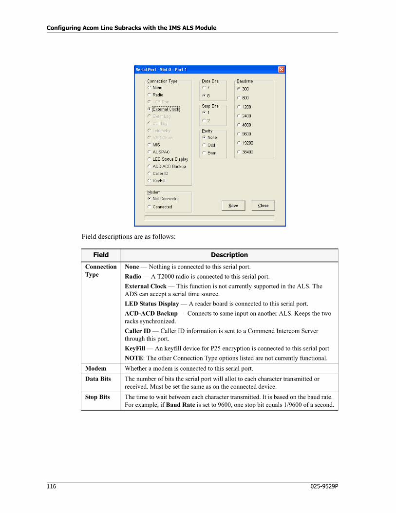
Configuring Acom Line Subracks with the IMS ALS Module
116 025-9529P
Field descriptions are as follows:
Field Description
ConnectionType
None — Nothing is connected to this serial port.
Radio — A T2000 radio is connected to this serial port.
External Clock — This function is not currently supported in the ALS. The ADS can accept a serial time source.
LED Status Display — A reader board is connected to this serial port.
ACD-ACD Backup — Connects to same input on another ALS. Keeps the two racks synchronized.
Caller ID — Caller ID information is sent to a Commend Intercom Server through this port.
KeyFill — An keyfill device for P25 encryption is connected to this serial port.
NOTE: The other Connection Type options listed are not currently functional.
Modem Whether a modem is connected to this serial port.
Data Bits The number of bits the serial port will allot to each character transmitted or received. Must be set the same as on the connected device.
Stop Bits The time to wait between each character transmitted. It is based on the baud rate. For example, if Baud Rate is set to 9600, one stop bit equals 1/9600 of a second.
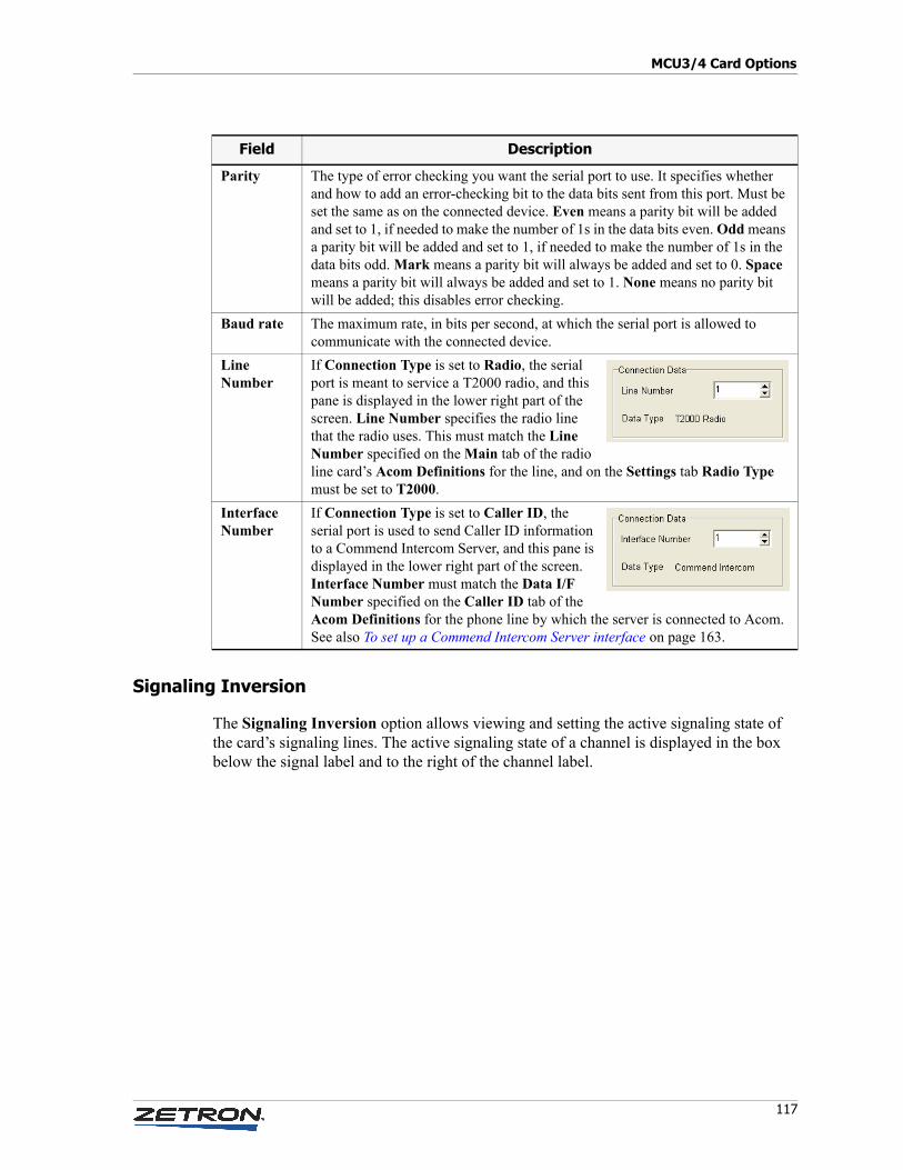
117
MCU3/4 Card Options
Signaling Inversion
The Signaling Inversion option allows viewing and setting the active signaling state of the card’s signaling lines. The active signaling state of a channel is displayed in the box below the signal label and to the right of the channel label.
Parity The type of error checking you want the serial port to use. It specifies whether and how to add an error-checking bit to the data bits sent from this port. Must be set the same as on the connected device. Even means a parity bit will be added and set to 1, if needed to make the number of 1s in the data bits even. Odd means a parity bit will be added and set to 1, if needed to make the number of 1s in the data bits odd. Mark means a parity bit will always be added and set to 0. Space means a parity bit will always be added and set to 1. None means no parity bit will be added; this disables error checking.
Baud rate The maximum rate, in bits per second, at which the serial port is allowed to communicate with the connected device.
Line Number
If Connection Type is set to Radio, the serial port is meant to service a T2000 radio, and this pane is displayed in the lower right part of the screen. Line Number specifies the radio line that the radio uses. This must match the Line Number specified on the Main tab of the radio line card’s Acom Definitions for the line, and on the Settings tab Radio Type must be set to T2000.
InterfaceNumber
If Connection Type is set to Caller ID, the serial port is used to send Caller ID information to a Commend Intercom Server, and this pane is displayed in the lower right part of the screen. Interface Number must match the Data I/F Number specified on the Caller ID tab of the Acom Definitions for the phone line by which the server is connected to Acom. See also To set up a Commend Intercom Server interface on page 163.
Field Description
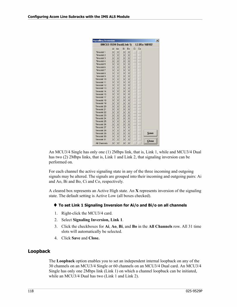
Configuring Acom Line Subracks with the IMS ALS Module
118 025-9529P
An MCU3/4 Single has only one (1) 2Mbps link, that is, Link 1, while and MCU3/4 Dual has two (2) 2Mbps links, that is, Link 1 and Link 2, that signaling inversion can be performed on.
For each channel the active signaling state in any of the three incoming and outgoing signals may be altered. The signals are grouped into their incoming and outgoing pairs: Ai and Ao, Bi and Bo, Ci and Co, respectively.
A cleared box represents an Active High state. An X represents inversion of the signaling state. The default setting is Active Low (all boxes checked).
♦ To set Link 1 Signaling Inversion for Ai/o and Bi/o on all channels
1. Right-click the MCU3/4 card.
2. Select Signaling Inversion, Link 1.
3. Click the checkboxes for Ai, Ao, Bi, and Bo in the All Channels row. All 31 time slots will automatically be selected.
4. Click Save and Close.
Loopback
The Loopback option enables you to set an independent internal loopback on any of the 30 channels on an MCU3/4 Single or 60 channels on an MCU3/4 Dual card. An MCU3/4 Single has only one 2Mbps link (Link 1) on which a channel loopback can be initiated, while an MCU3/4 Dual has two (Link 1 and Link 2).
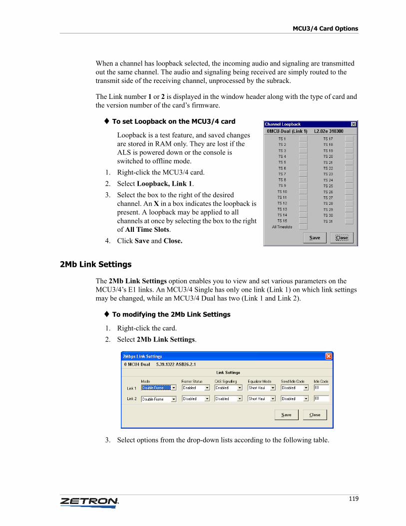
119
MCU3/4 Card Options
When a channel has loopback selected, the incoming audio and signaling are transmitted out the same channel. The audio and signaling being received are simply routed to the transmit side of the receiving channel, unprocessed by the subrack.
The Link number 1 or 2 is displayed in the window header along with the type of card and the version number of the card’s firmware.
♦ To set Loopback on the MCU3/4 card
Loopback is a test feature, and saved changes are stored in RAM only. They are lost if the ALS is powered down or the console is switched to offline mode.
1. Right-click the MCU3/4 card.
2. Select Loopback, Link 1.
3. Select the box to the right of the desired channel. An X in a box indicates the loopback is present. A loopback may be applied to all channels at once by selecting the box to the right of All Time Slots.
4. Click Save and Close.
2Mb Link Settings
The 2Mb Link Settings option enables you to view and set various parameters on the MCU3/4’s E1 links. An MCU3/4 Single has only one link (Link 1) on which link settings may be changed, while an MCU3/4 Dual has two (Link 1 and Link 2).
♦ To modifying the 2Mb Link Settings
1. Right-click the card.
2. Select 2Mb Link Settings.
3. Select options from the drop-down lists according to the following table.
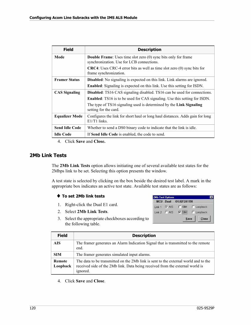
Configuring Acom Line Subracks with the IMS ALS Module
120 025-9529P
4. Click Save and Close.
2Mb Link Tests
The 2Mb Link Tests option allows initiating one of several available test states for the 2Mbps link to be set. Selecting this option presents the window.
A test state is selected by clicking on the box beside the desired test label. A mark in the appropriate box indicates an active test state. Available test states are as follows:
♦ To set 2Mb link tests
1. Right-click the Dual E1 card.
2. Select 2Mb Link Tests.
3. Select the appropriate checkboxes according to the following table.
4. Click Save and Close.
Field Description
Mode Double Frame: Uses time slot zero (0) sync bits only for frame synchronization. Use for LCB connections.
CRC4: Uses CRC-4 error bits as well as time slot zero (0) sync bits for frame synchronization.
Framer Status Disabled: No signaling is expected on this link. Link alarms are ignored.
Enabled: Signaling is expected on this link. Use this setting for ISDN.
CAS Signaling Disabled: TS16 CAS signaling disabled. TS16 can be used for connections.
Enabled: TS16 is to be used for CAS signaling. Use this setting for ISDN.
The type of TS16 signaling used is determined by the Link Signaling setting for the card.
Equalizer Mode Configures the link for short haul or long haul distances. Adds gain for long E1/T1 links.
Send Idle Code Whether to send a DS0 binary code to indicate that the link is idle.
Idle Code If Send Idle Code is enabled, the code to send.
Field Description
AIS The framer generates an Alarm Indication Signal that is transmitted to the remote end.
SIM The framer generates simulated input alarms.
RemoteLoopback
The data to be transmitted on the 2Mb link is sent to the external world and to the received side of the 2Mb link. Data being received from the external world is ignored.
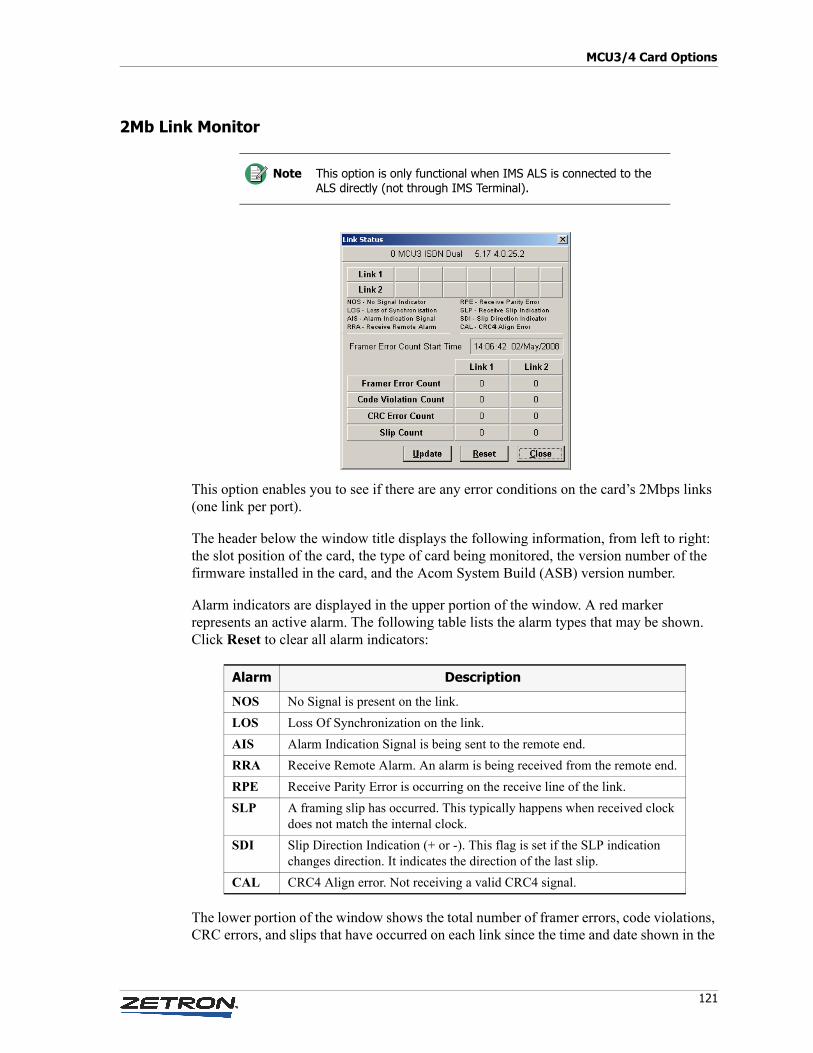
121
MCU3/4 Card Options
2Mb Link Monitor
This option enables you to see if there are any error conditions on the card’s 2Mbps links (one link per port).
The header below the window title displays the following information, from left to right: the slot position of the card, the type of card being monitored, the version number of the firmware installed in the card, and the Acom System Build (ASB) version number.
Alarm indicators are displayed in the upper portion of the window. A red marker represents an active alarm. The following table lists the alarm types that may be shown. Click Reset to clear all alarm indicators:
The lower portion of the window shows the total number of framer errors, code violations, CRC errors, and slips that have occurred on each link since the time and date shown in the
Note This option is only functional when IMS ALS is connected to the ALS directly (not through IMS Terminal).
Alarm Description
NOS No Signal is present on the link.
LOS Loss Of Synchronization on the link.
AIS Alarm Indication Signal is being sent to the remote end.
RRA Receive Remote Alarm. An alarm is being received from the remote end.
RPE Receive Parity Error is occurring on the receive line of the link.
SLP A framing slip has occurred. This typically happens when received clock does not match the internal clock.
SDI Slip Direction Indication (+ or -). This flag is set if the SLP indication changes direction. It indicates the direction of the last slip.
CAL CRC4 Align error. Not receiving a valid CRC4 signal.
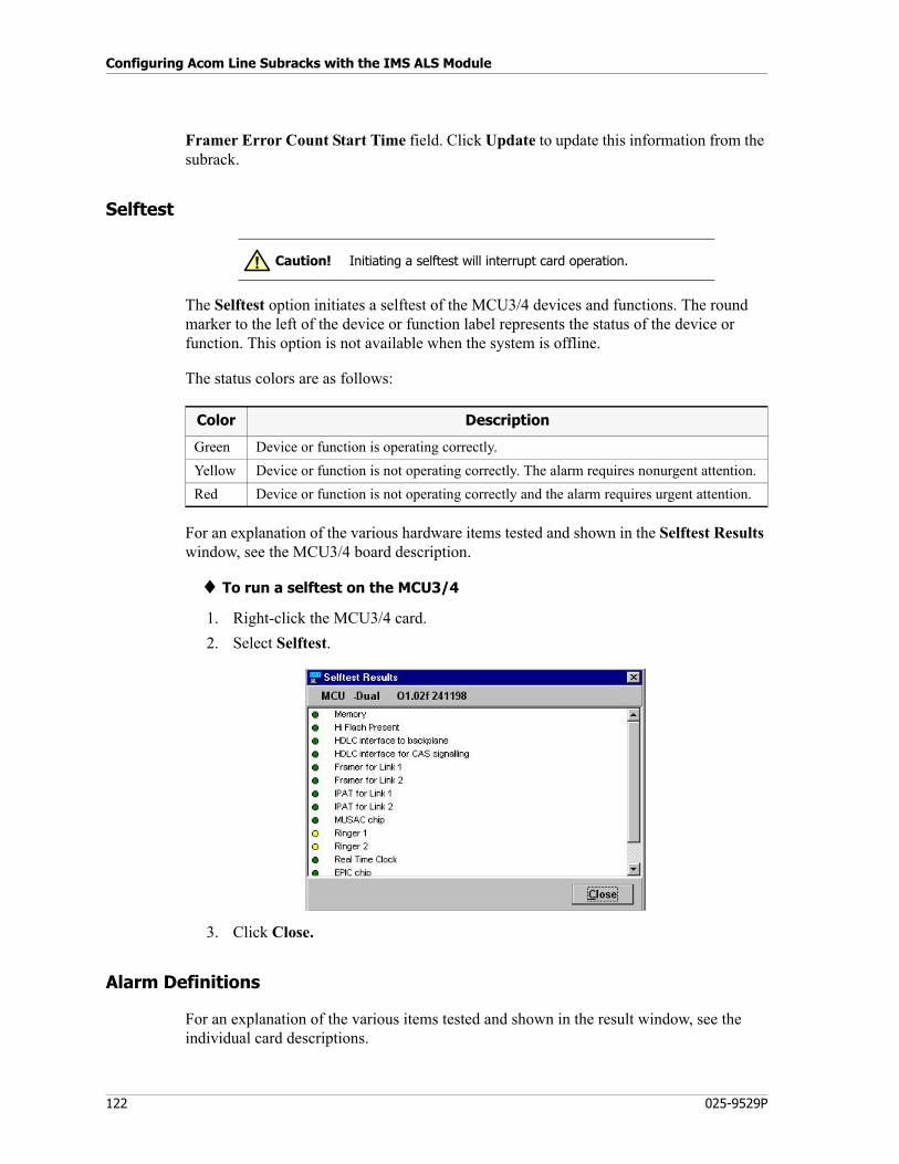
Configuring Acom Line Subracks with the IMS ALS Module
122 025-9529P
Framer Error Count Start Time field. Click Update to update this information from the subrack.
Selftest
The Selftest option initiates a selftest of the MCU3/4 devices and functions. The round marker to the left of the device or function label represents the status of the device or function. This option is not available when the system is offline.
The status colors are as follows:
For an explanation of the various hardware items tested and shown in the Selftest Results window, see the MCU3/4 board description.
♦ To run a selftest on the MCU3/4
1. Right-click the MCU3/4 card.
2. Select Selftest.
3. Click Close.
Alarm Definitions
For an explanation of the various items tested and shown in the result window, see the individual card descriptions.
Caution! Initiating a selftest will interrupt card operation.!
Color Description
Green Device or function is operating correctly.
Yellow Device or function is not operating correctly. The alarm requires nonurgent attention.
Red Device or function is not operating correctly and the alarm requires urgent attention.
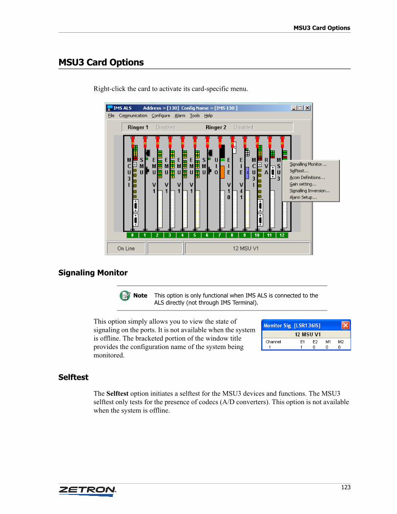
123
MSU3 Card Options
MSU3 Card Options
Right-click the card to activate its card-specific menu.
Signaling Monitor
This option simply allows you to view the state of signaling on the ports. It is not available when the system is offline. The bracketed portion of the window title provides the configuration name of the system being monitored.
Selftest
The Selftest option initiates a selftest for the MSU3 devices and functions. The MSU3 selftest only tests for the presence of codecs (A/D converters). This option is not available when the system is offline.
Note This option is only functional when IMS ALS is connected to the ALS directly (not through IMS Terminal).

Configuring Acom Line Subracks with the IMS ALS Module
124 025-9529P
♦ To run a self-test on the MSU3 card
1. Right-click the Dual E1 card.
2. Select Selftest.
3. Click Close.
Acom Definitions
The MSU3 card has four channels that can be defined. MSU3 channels are often used for rack or system tone generation.
♦ To configure the MSU3 card
1. Right-click the MSU3 card.
2. Select Acom Definitions.
3. Click the Channel that you need to configure. The Channel Definitions Detail screen appears:
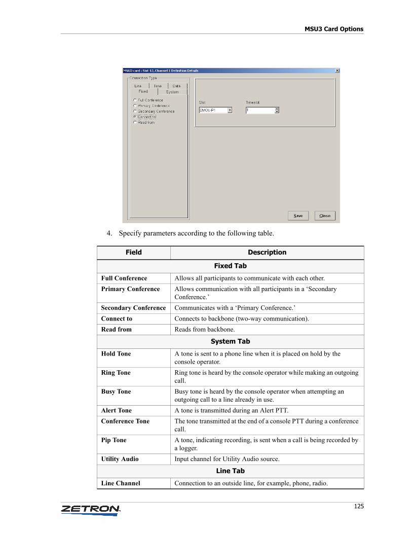
125
MSU3 Card Options
4. Specify parameters according to the following table.
Field Description
Fixed Tab
Full Conference Allows all participants to communicate with each other.
Primary Conference Allows communication with all participants in a ‘Secondary Conference.’
Secondary Conference Communicates with a ‘Primary Conference.’
Connect to Connects to backbone (two-way communication).
Read from Reads from backbone.
System Tab
Hold Tone A tone is sent to a phone line when it is placed on hold by the console operator.
Ring Tone Ring tone is heard by the console operator while making an outgoing call.
Busy Tone Busy tone is heard by the console operator when attempting an outgoing call to a line already in use.
Alert Tone A tone is transmitted during an Alert PTT.
Conference Tone The tone transmitted at the end of a console PTT during a conference call.
Pip Tone A tone, indicating recording, is sent when a call is being recorded by a logger.
Utility Audio Input channel for Utility Audio source.
Line Tab
Line Channel Connection to an outside line, for example, phone, radio.
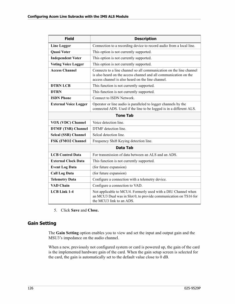
Configuring Acom Line Subracks with the IMS ALS Module
126 025-9529P
5. Click Save and Close.
Gain Setting
The Gain Setting option enables you to view and set the input and output gain and the MSU3’s impedance on the audio channel.
When a new, previously not configured system or card is powered up, the gain of the card is the implemented hardware gain of the card. When the gain setup screen is selected for the card, the gain is automatically set to the default value close to 0 dB.
Line Logger Connection to a recording device to record audio from a local line.
Quasi Voter This option is not currently supported.
Independent Voter This option is not currently supported.
Voting Voice Logger This option is not currently supported.
Access Channel Connects to a line channel so all communication on the line channel is also heard on the access channel and all communication on the access channel is also heard on the line channel.
DTRN LCB This function is not currently supported.
DTRN This function is not currently supported.
ISDN Phone Connect to ISDN Network.
External Voice Logger Operator or line audio is paralleled to logger channels by the connected ADS. Used if the line to be logged is in a different ALS.
Tone Tab
VOX (VDC) Channel Voice detection line.
DTMF (TSR) Channel DTMF detection line.
Selcal (SSR) Channel Selcal detection line.
FSK (FMO2 Channel Frequency Shift Keying detection line.
Data Tab
LCB Control Data For transmission of data between an ALS and an ADS.
External Clock Data This function is not currently supported.
Event Log Data (for future expansion)
Call Log Data (for future expansion)
Telemetry Data Configure a connection with a telemetry device.
VAD Chain Configure a connection to VAD.
LCB Link 1-4 Not applicable to MCU4. Formerly used with a DIU Channel when an MCU3 Dual was in Slot 0, to provide communication on TS16 for the MCU3 link to an ADS.
Field Description
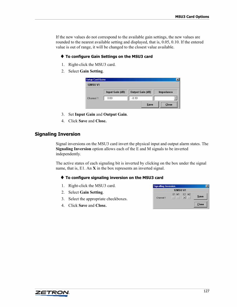
127
MSU3 Card Options
If the new values do not correspond to the available gain settings, the new values are rounded to the nearest available setting and displayed, that is, 0.05, 0.10. If the entered value is out of range, it will be changed to the closest value available.
♦ To configure Gain Settings on the MSU3 card
1. Right-click the MSU3 card.
2. Select Gain Setting.
3. Set Input Gain and Output Gain.
4. Click Save and Close.
Signaling Inversion
Signal inversions on the MSU3 card invert the physical input and output alarm states. The Signaling Inversion option allows each of the E and M signals to be inverted independently.
The active states of each signaling bit is inverted by clicking on the box under the signal name, that is, E1. An X in the box represents an inverted signal.
♦ To configure signaling inversion on the MSU3 card
1. Right-click the MSU3 card.
2. Select Gain Setting.
3. Select the appropriate checkboxes.
4. Click Save and Close.
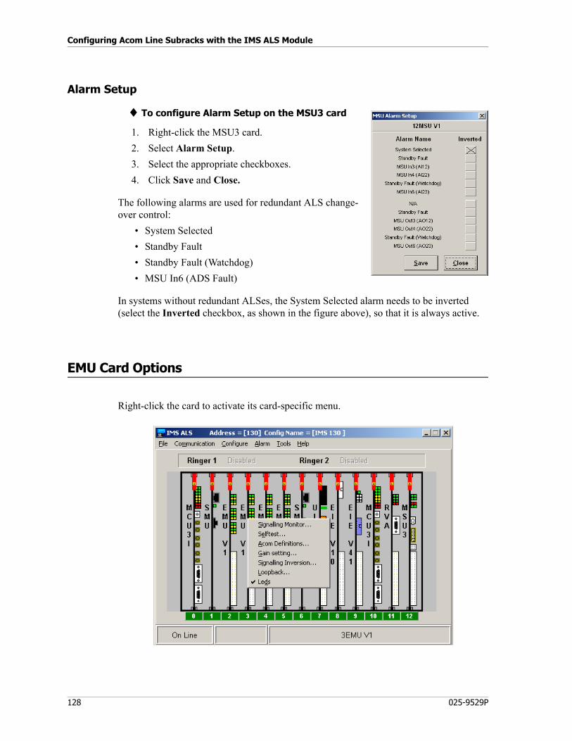
Configuring Acom Line Subracks with the IMS ALS Module
128 025-9529P
Alarm Setup
♦ To configure Alarm Setup on the MSU3 card
1. Right-click the MSU3 card.
2. Select Alarm Setup.
3. Select the appropriate checkboxes.
4. Click Save and Close.
The following alarms are used for redundant ALS change-over control:
• System Selected
• Standby Fault
• Standby Fault (Watchdog)
• MSU In6 (ADS Fault)
In systems without redundant ALSes, the System Selected alarm needs to be inverted (select the Inverted checkbox, as shown in the figure above), so that it is always active.
EMU Card Options
Right-click the card to activate its card-specific menu.
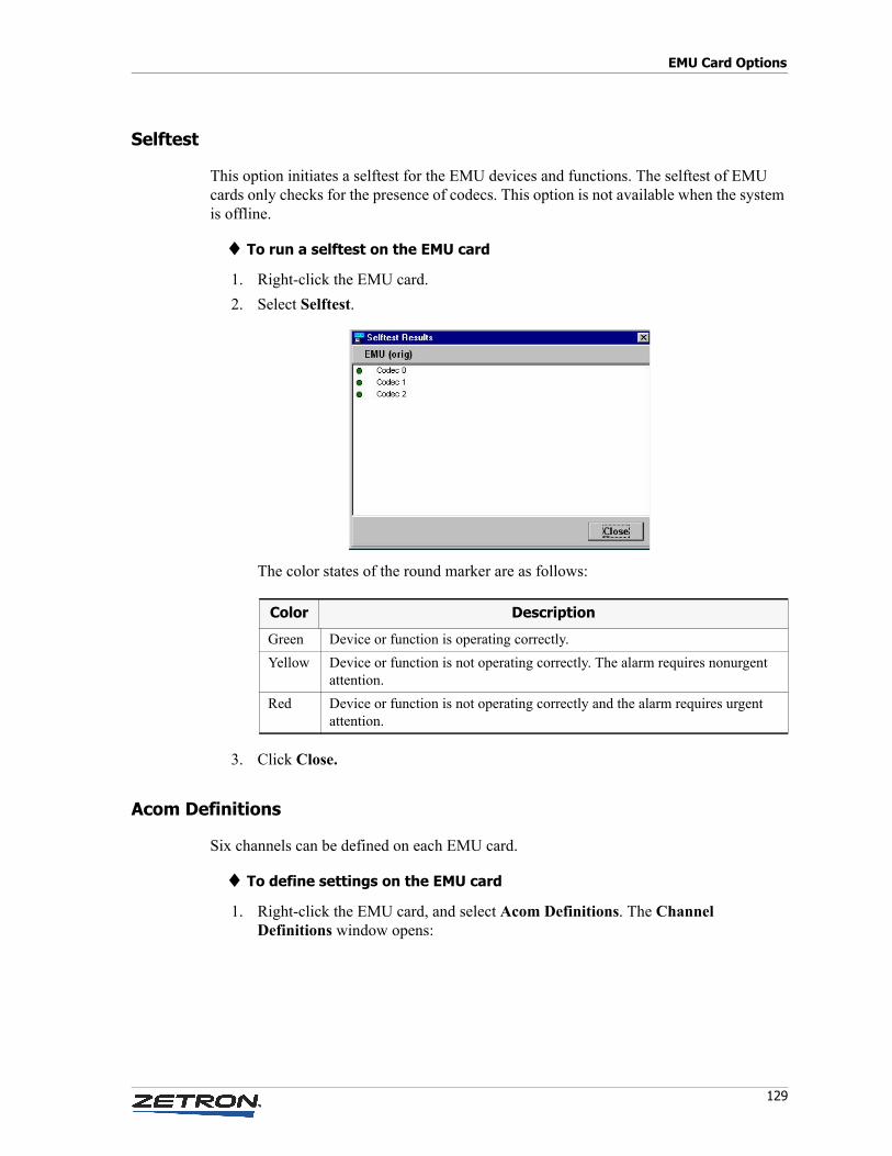
129
EMU Card Options
Selftest
This option initiates a selftest for the EMU devices and functions. The selftest of EMU cards only checks for the presence of codecs. This option is not available when the system is offline.
♦ To run a selftest on the EMU card
1. Right-click the EMU card.
2. Select Selftest.
The color states of the round marker are as follows:
3. Click Close.
Acom Definitions
Six channels can be defined on each EMU card.
♦ To define settings on the EMU card
1. Right-click the EMU card, and select Acom Definitions. The Channel Definitions window opens:
Color Description
Green Device or function is operating correctly.
Yellow Device or function is not operating correctly. The alarm requires nonurgent attention.
Red Device or function is not operating correctly and the alarm requires urgent attention.
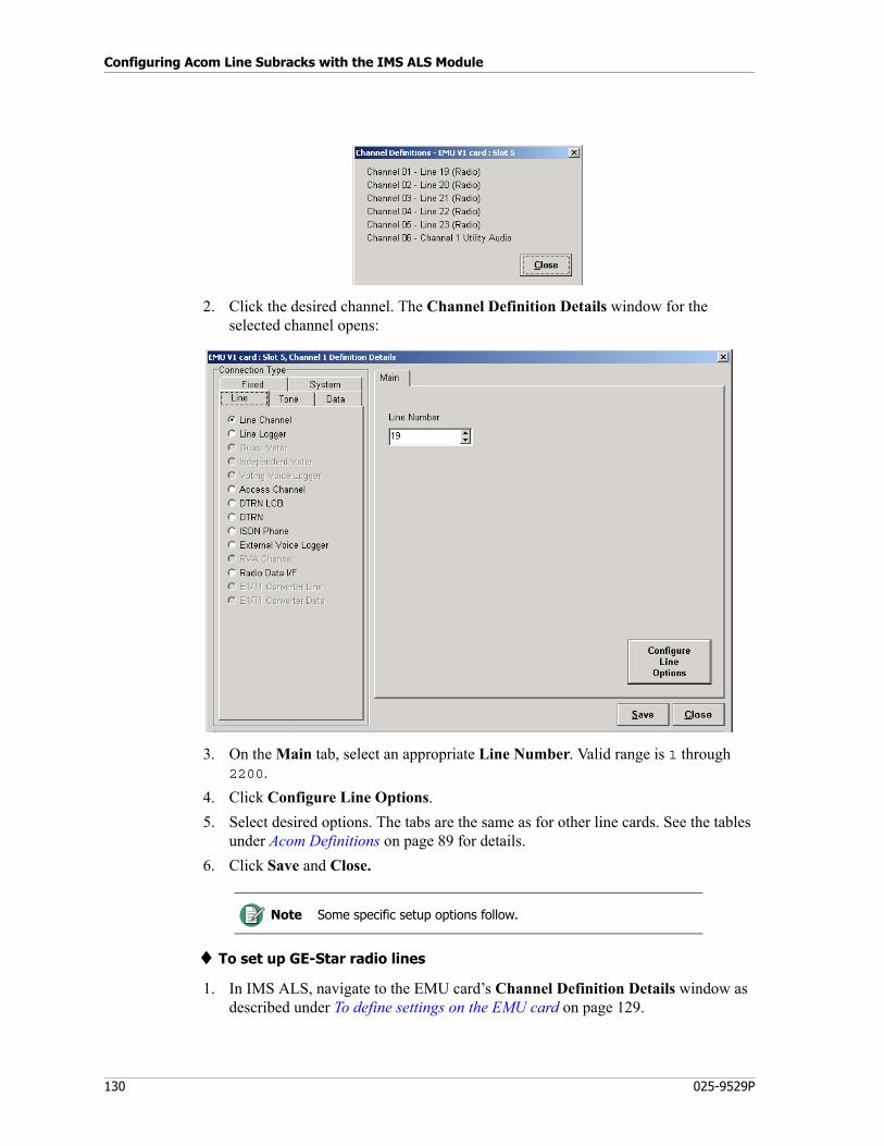
Configuring Acom Line Subracks with the IMS ALS Module
130 025-9529P
2. Click the desired channel. The Channel Definition Details window for the selected channel opens:
3. On the Main tab, select an appropriate Line Number. Valid range is 1 through 2200.
4. Click Configure Line Options.
5. Select desired options. The tabs are the same as for other line cards. See the tables under Acom Definitions on page 89 for details.
6. Click Save and Close.
♦ To set up GE-Star radio lines
1. In IMS ALS, navigate to the EMU card’s Channel Definition Details window as described under To define settings on the EMU card on page 129.
Note Some specific setup options follow.
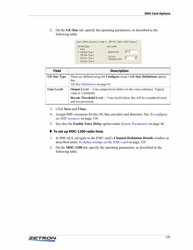
131
EMU Card Options
2. On the GE-Star tab, specify the operating parameters, as described in the following table.
3. Click Save and Close.
4. Assign SMU resources for the GE-Star encoders and detectors. See To configure an SMU resource on page 138.
5. See also the Enable Voice Delay option under System Parameters on page 46.
♦ To set up MDC-1200 radio lines
1. In IMS ALS, navigate to the EMU card’s Channel Definition Details window as described under To define settings on the EMU card on page 129.
2. On the MDC-1200 tab, specify the operating parameters, as described in the following table.
Field Description
GE-Star Type These are defined using the Configure menu’s GE-Star Definitions option. See GE-Star Definitions on page 63.
Line Levels Output Level — Line output level relative to the voice reference. Typical value is 0 (default).
Decode Threshold Level — Line levels below this will be considered noise and not processed.
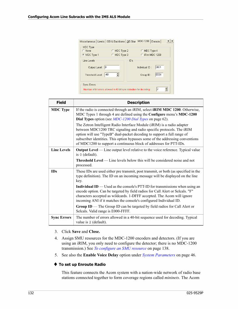
Configuring Acom Line Subracks with the IMS ALS Module
132 025-9529P
3. Click Save and Close.
4. Assign SMU resources for the MDC-1200 encoders and detectors. (If you are using an iRIM, you only need to configure the detector; there is no MDC-1200 transmission.) See To configure an SMU resource on page 138.
5. See also the Enable Voice Delay option under System Parameters on page 46.
♦ To set up Enroute Radio
This feature connects the Acom system with a nation-wide network of radio base stations connected together to form coverage regions called mininets. The Acom
Field Description
MDC Type If the radio is connected through an iRIM, select iRIM MDC 1200. Otherwise, MDC Types 1 through 4 are defined using the Configure menu’s MDC-1200 Dial Types option (see MDC-1200 Dial Types on page 62).
The Zetron Intelligent Radio Interface Module (iRIM) is a radio adapter between MDC1200 TRC signaling and radio specific protocols. The iRIM option will use "TypeB" dual-packet decoding to support a full range of subscriber identities. This option bypasses some of the addressing conventions of MDC1200 to support a continuous block of addresses for PTT-IDs.
Line Levels Output Level — Line output level relative to the voice reference. Typical value is 0 (default).
Threshold Level — Line levels below this will be considered noise and not processed.
IDs These IDs are used either pre transmit, post transmit, or both (as specified in the type definition). The ID on an incoming message will be displayed on the line key.
Individual ID — Used as the console's PTT-ID for transmissions when using an encode option. Can be targeted by field radios for Call Alert or Selcals. "F" characters accepted as wildcards. 1-DFFF accepted. The Acom will ignore incoming ANI if it matches the console's configured Individual ID.
Group ID — The Group ID can be targeted by field radios for Call Alert or Selcals. Valid range is E000-FFFF.
Sync Errors The number of errors allowed in a 40-bit sequence used for decoding. Typical value is 2 (default).
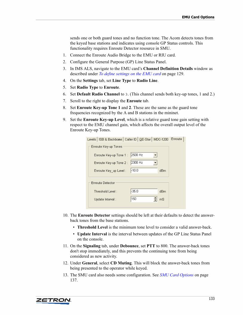
133
EMU Card Options
sends one or both guard tones and no function tone. The Acom detects tones from the keyed base stations and indicates using console GP Status controls. This functionality requires Enroute Detector resource in SMU.
1. Connect the Enroute Audio Bridge to the EMU or RIU card.
2. Configure the General Purpose (GP) Line Status Panel.
3. In IMS ALS, navigate to the EMU card’s Channel Definition Details window as described under To define settings on the EMU card on page 129.
4. On the Settings tab, set Line Type to Radio Line.
5. Set Radio Type to Enroute.
6. Set Default Radio Channel to 3. (This channel sends both key-up tones, 1 and 2.)
7. Scroll to the right to display the Enroute tab.
8. Set Enroute Key-up Tone 1 and 2. These are the same as the guard tone frequencies recognized by the A and B stations in the mininet.
9. Set the Enroute Key-up Level, which is a relative guard tone gain setting with respect to the EMU channel gain, which affects the overall output level of the Enroute Key-up Tones.
10. The Enroute Detector settings should be left at their defaults to detect the answer-back tones from the base stations.
• Threshold Level is the minimum tone level to consider a valid answer-back.
• Update Interval is the interval between updates of the GP Line Status Panel on the console.
11. On the Signaling tab, under Debounce, set PTT to 800. The answer-back tones don't stop immediately, and this prevents the continuing tone from being considered as new activity.
12. Under General, select CD Muting. This will block the answer-back tones from being presented to the operator while keyed.
13. The SMU card also needs some configuration. See SMU Card Options on page 137.
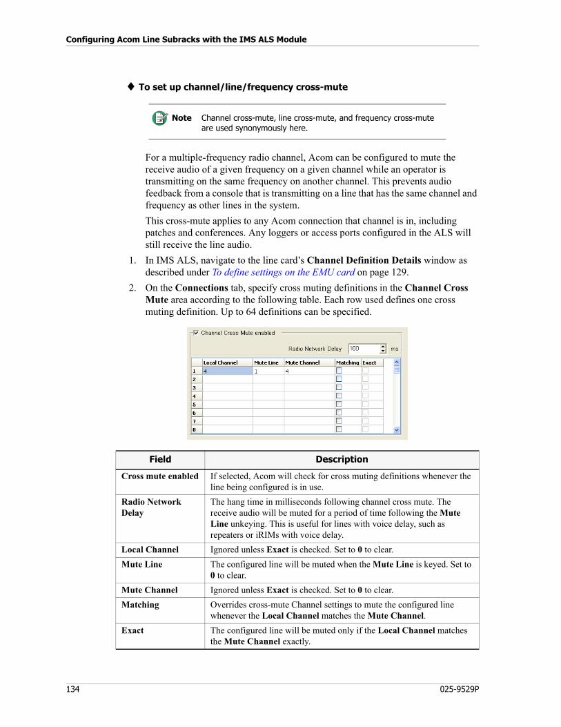
Configuring Acom Line Subracks with the IMS ALS Module
134 025-9529P
♦ To set up channel/line/frequency cross-mute
For a multiple-frequency radio channel, Acom can be configured to mute the receive audio of a given frequency on a given channel while an operator is transmitting on the same frequency on another channel. This prevents audio feedback from a console that is transmitting on a line that has the same channel and frequency as other lines in the system.
This cross-mute applies to any Acom connection that channel is in, including patches and conferences. Any loggers or access ports configured in the ALS will still receive the line audio.
1. In IMS ALS, navigate to the line card’s Channel Definition Details window as described under To define settings on the EMU card on page 129.
2. On the Connections tab, specify cross muting definitions in the Channel Cross Mute area according to the following table. Each row used defines one cross muting definition. Up to 64 definitions can be specified.
Note Channel cross-mute, line cross-mute, and frequency cross-mute are used synonymously here.
Field Description
Cross mute enabled If selected, Acom will check for cross muting definitions whenever the line being configured is in use.
Radio Network Delay
The hang time in milliseconds following channel cross mute. The receive audio will be muted for a period of time following the Mute Line unkeying. This is useful for lines with voice delay, such as repeaters or iRIMs with voice delay.
Local Channel Ignored unless Exact is checked. Set to 0 to clear.
Mute Line The configured line will be muted when the Mute Line is keyed. Set to 0 to clear.
Mute Channel Ignored unless Exact is checked. Set to 0 to clear.
Matching Overrides cross-mute Channel settings to mute the configured line whenever the Local Channel matches the Mute Channel.
Exact The configured line will be muted only if the Local Channel matches the Mute Channel exactly.
135
EMU Card Options
For example, the configuration shown in the figure above enables the following cross mute scenarios. Assuming the line being configured is line 1, line 1’s Rx audio is muted if:
• Line 2 is transmitting on channel 10, and line 1 is on channel 5.
• Line 3 is transmitting on the same channel as line 1.
• Line 4 is transmitting on any channel.
♦ To set up a listen-in line
This feature enables an operator to “listen in” on a phone call that is currently being handled at another console. (Only Zetron Series 3200 phones are supported.) Audio is passed one-way from the original console to the listening operator’s console. The audio is automatically routed to the headset. If radio audio is already or subsequently routed to the headset, it is automatically switched to the select speaker; the phone audio remains in the headset. The listening operator's transmit audio is not passed to the caller or to the original console.
A PTT can still be performed on a radio channel while a listen-in is active. Selecting a radio channel does not affect listen-in line selection.
If the original operator changes lines, the listening operator will still be listening in, on the newly active line. An operator can only listen in on one console’s call at a time. If the listening operator selects another listen-in line, she will be disconnected from the first and connected to the second.
An operator cannot have both a regular phone line and a listen-in line active at the same time.
This feature is enabled by configuring the EMU as a phone line and configuring the phone and radio audio to be sent to the console on separate time slots, which are the Headset and Audio Panel audio interfaces. By sending the phone (Headset time slot) and radio (Audio Panel time slot) audio to the console separately, the ACU can route the audio to different audio interfaces.
1. In IMS ALS, navigate to the EMU card’s Channel Definition Details window as described under To define settings on the EMU card on page 129.
2. In the Connection Type pane, on the Line tab, select Line Channel.
3. On the Settings tab, set Line Type to Phone Line and Dial Type to None.
4. On the Signaling tab, make sure CD Muting is unselected.
5. On the Connection Data tab, set Line Type to CB Line.
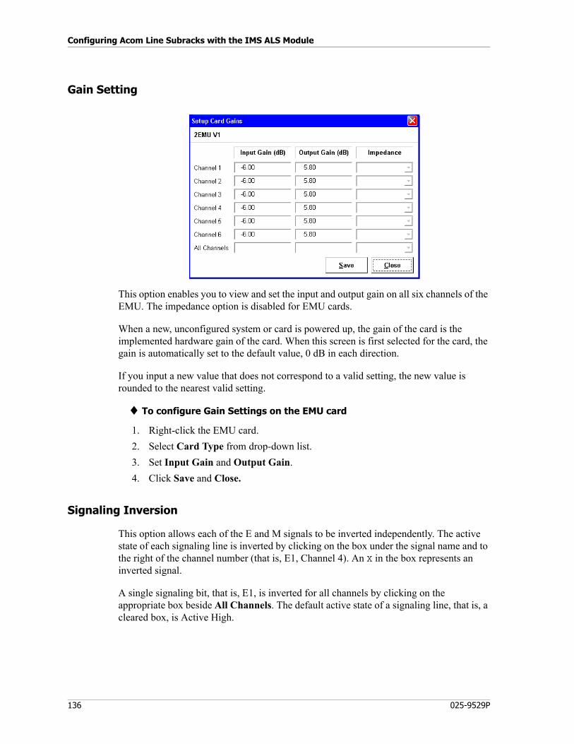
Configuring Acom Line Subracks with the IMS ALS Module
136 025-9529P
Gain Setting
This option enables you to view and set the input and output gain on all six channels of the EMU. The impedance option is disabled for EMU cards.
When a new, unconfigured system or card is powered up, the gain of the card is the implemented hardware gain of the card. When this screen is first selected for the card, the gain is automatically set to the default value, 0 dB in each direction.
If you input a new value that does not correspond to a valid setting, the new value is rounded to the nearest valid setting.
♦ To configure Gain Settings on the EMU card
1. Right-click the EMU card.
2. Select Card Type from drop-down list.
3. Set Input Gain and Output Gain.
4. Click Save and Close.
Signaling Inversion
This option allows each of the E and M signals to be inverted independently. The active state of each signaling line is inverted by clicking on the box under the signal name and to the right of the channel number (that is, E1, Channel 4). An X in the box represents an inverted signal.
A single signaling bit, that is, E1, is inverted for all channels by clicking on the appropriate box beside All Channels. The default active state of a signaling line, that is, a cleared box, is Active High.
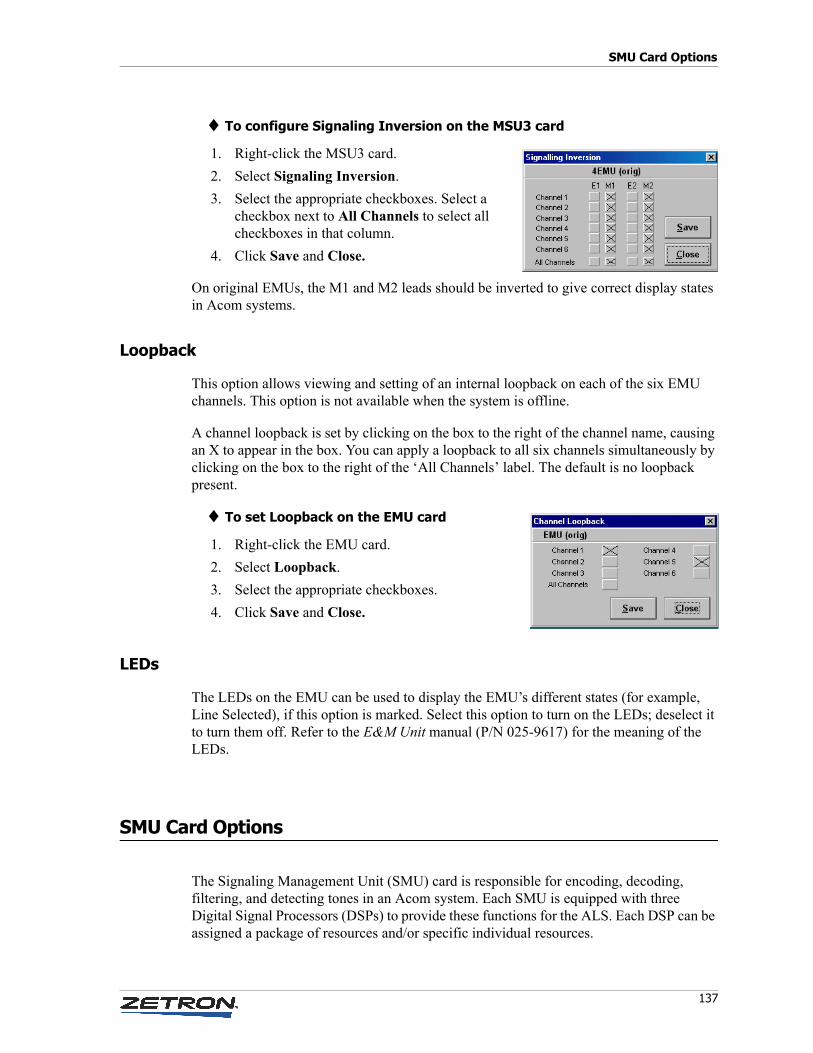
137
SMU Card Options
♦ To configure Signaling Inversion on the MSU3 card
1. Right-click the MSU3 card.
2. Select Signaling Inversion.
3. Select the appropriate checkboxes. Select a checkbox next to All Channels to select all checkboxes in that column.
4. Click Save and Close.
On original EMUs, the M1 and M2 leads should be inverted to give correct display states in Acom systems.
Loopback
This option allows viewing and setting of an internal loopback on each of the six EMU channels. This option is not available when the system is offline.
A channel loopback is set by clicking on the box to the right of the channel name, causing an X to appear in the box. You can apply a loopback to all six channels simultaneously by clicking on the box to the right of the ‘All Channels’ label. The default is no loopback present.
♦ To set Loopback on the EMU card
1. Right-click the EMU card.
2. Select Loopback.
3. Select the appropriate checkboxes.
4. Click Save and Close.
LEDs
The LEDs on the EMU can be used to display the EMU’s different states (for example, Line Selected), if this option is marked. Select this option to turn on the LEDs; deselect it to turn them off. Refer to the E&M Unit manual (P/N 025-9617) for the meaning of the LEDs.
SMU Card Options
The Signaling Management Unit (SMU) card is responsible for encoding, decoding, filtering, and detecting tones in an Acom system. Each SMU is equipped with three Digital Signal Processors (DSPs) to provide these functions for the ALS. Each DSP can be assigned a package of resources and/or specific individual resources.
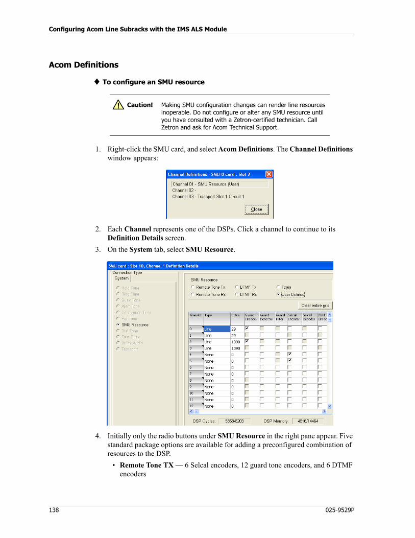
Configuring Acom Line Subracks with the IMS ALS Module
138 025-9529P
Acom Definitions
♦ To configure an SMU resource
1. Right-click the SMU card, and select Acom Definitions. The Channel Definitions window appears:
2. Each Channel represents one of the DSPs. Click a channel to continue to its Definition Details screen.
3. On the System tab, select SMU Resource.
4. Initially only the radio buttons under SMU Resource in the right pane appear. Five standard package options are available for adding a preconfigured combination of resources to the DSP.
• Remote Tone TX — 6 Selcal encoders, 12 guard tone encoders, and 6 DTMF encoders
Caution! Making SMU configuration changes can render line resources inoperable. Do not configure or alter any SMU resource until you have consulted with a Zetron-certified technician. Call Zetron and ask for Acom Technical Support.
!
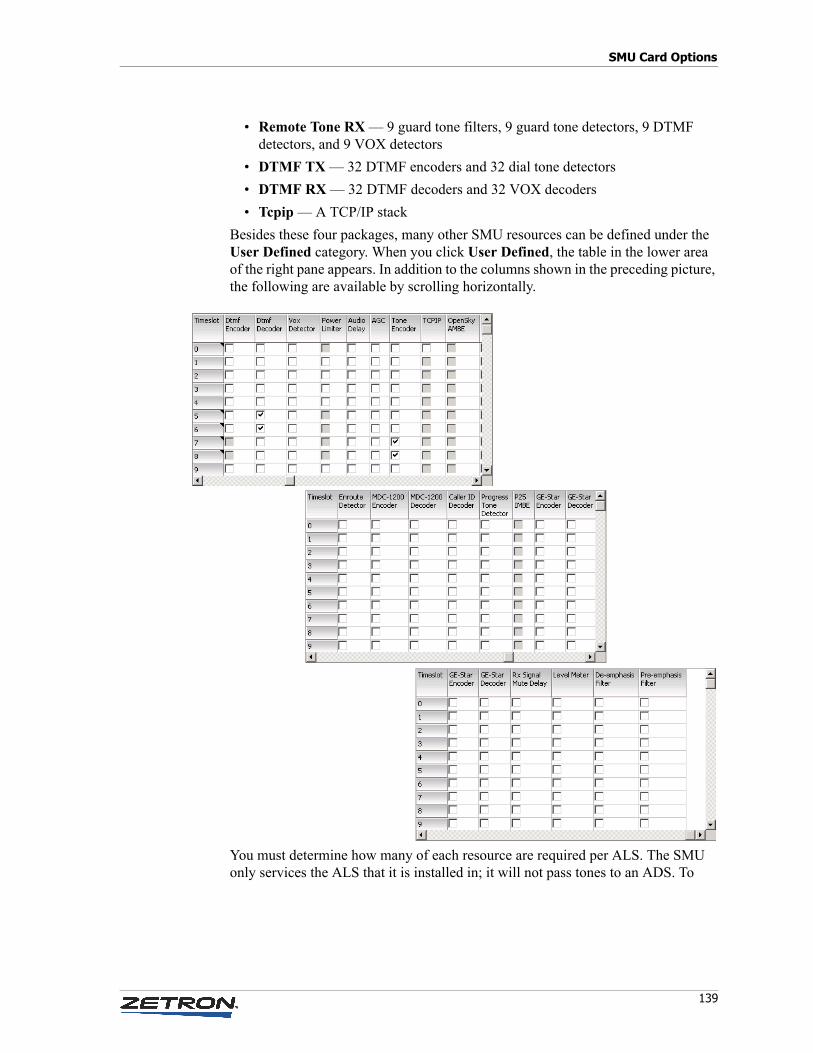
139
SMU Card Options
• Remote Tone RX — 9 guard tone filters, 9 guard tone detectors, 9 DTMF detectors, and 9 VOX detectors
• DTMF TX — 32 DTMF encoders and 32 dial tone detectors
• DTMF RX — 32 DTMF decoders and 32 VOX decoders
• Tcpip — A TCP/IP stack
Besides these four packages, many other SMU resources can be defined under the User Defined category. When you click User Defined, the table in the lower area of the right pane appears. In addition to the columns shown in the preceding picture, the following are available by scrolling horizontally.
You must determine how many of each resource are required per ALS. The SMU only services the ALS that it is installed in; it will not pass tones to an ADS. To
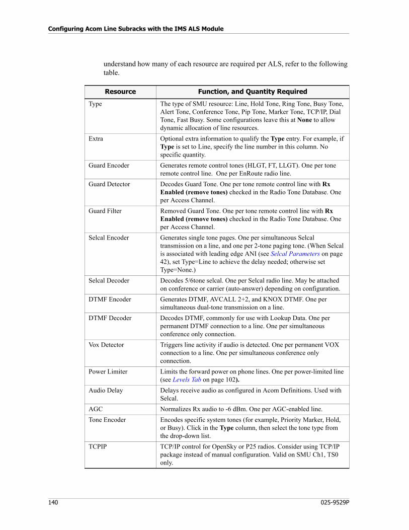
Configuring Acom Line Subracks with the IMS ALS Module
140 025-9529P
understand how many of each resource are required per ALS, refer to the following table.
Resource Function, and Quantity Required
Type The type of SMU resource: Line, Hold Tone, Ring Tone, Busy Tone, Alert Tone, Conference Tone, Pip Tone, Marker Tone, TCP/IP, Dial Tone, Fast Busy. Some configurations leave this at None to allow dynamic allocation of line resources.
Extra Optional extra information to qualify the Type entry. For example, if Type is set to Line, specify the line number in this column. No specific quantity.
Guard Encoder Generates remote control tones (HLGT, FT, LLGT). One per tone remote control line. One per EnRoute radio line.
Guard Detector Decodes Guard Tone. One per tone remote control line with Rx Enabled (remove tones) checked in the Radio Tone Database. One per Access Channel.
Guard Filter Removed Guard Tone. One per tone remote control line with Rx Enabled (remove tones) checked in the Radio Tone Database. One per Access Channel.
Selcal Encoder Generates single tone pages. One per simultaneous Selcal transmission on a line, and one per 2-tone paging tone. (When Selcal is associated with leading edge ANI (see Selcal Parameters on page 42), set Type=Line to achieve the delay needed; otherwise set Type=None.)
Selcal Decoder Decodes 5/6tone selcal. One per Selcal radio line. May be attached on conference or carrier (auto-answer) depending on configuration.
DTMF Encoder Generates DTMF, AVCALL 2+2, and KNOX DTMF. One per simultaneous dual-tone transmission on a line.
DTMF Decoder Decodes DTMF, commonly for use with Lookup Data. One per permanent DTMF connection to a line. One per simultaneous conference only connection.
Vox Detector Triggers line activity if audio is detected. One per permanent VOX connection to a line. One per simultaneous conference only connection.
Power Limiter Limits the forward power on phone lines. One per power-limited line (see Levels Tab on page 102).
Audio Delay Delays receive audio as configured in Acom Definitions. Used with Selcal.
AGC Normalizes Rx audio to -6 dBm. One per AGC-enabled line.
Tone Encoder Encodes specific system tones (for example, Priority Marker, Hold, or Busy). Click in the Type column, then select the tone type from the drop-down list.
TCPIP TCP/IP control for OpenSky or P25 radios. Consider using TCP/IP package instead of manual configuration. Valid on SMU Ch1, TS0 only.
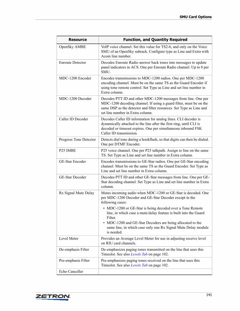
141
SMU Card Options
OpenSky AMBE VoIP voice channel. Set this value for TS2-6, and only on the Voice SMU of an OpenSky subrack. Configure type as Line and Extra with Acom line number.
Enroute Detector Decodes Enroute Radio answer back tones into messages to update panel indicators in ACS. One per Enroute Radio channel. Up to 8 per SMU.
MDC-1200 Encoder Encodes transmissions to MDC-1200 radios. One per MDC-1200 encoding channel. Must be on the same TS as the Guard Encoder if using tone remote control. Set Type as Line and set line number in Extra column.
MDC-1200 Decoder Decodes PTT ID and other MDC-1200 messages from line. One per MDC-1200 decoding channel. If using a guard filter, must be on the same DSP as the detector and filter resources. Set Type as Line and set line number in Extra column.
Caller ID Decoder Decodes Caller ID information for analog lines. CLI decoder is dynamically attached to the line after the first ring, until CLI is decoded or timeout expires. One per simultaneous inbound FSK Caller ID transmission.
Progress Tone Detector Detects dial tone during a hookflash, so that digits can then be dialed. One per DTMF Encoder.
P25 IMBE P25 voice channel. One per P25 talkpath. Assign to line on the same TS. Set Type as Line and set line number in Extra column.
GE-Star Encoder Encodes transmissions to GE-Star radios. One per GE-Star encoding channel. Must be on the same TS as the Guard Encoder. Set Type as Line and set line number in Extra column.
GE-Star Decoder Decodes PTT ID and other GE-Star messages from line. One per GE-Star decoding channel. Set Type as Line and set line number in Extra column.
Rx Signal Mute Delay Mutes incoming audio when MDC-1200 or GE-Star is decoded. One per MDC-1200 Decoder and GE-Star Decoder except in the following cases:
• MDC-1200 or GE-Star is being decoded over a Tone Remote line, in which case a mute/delay feature is built into the Guard Filter.
• MDC-1200 and GE-Star Decoders are being allocated to the same line, in which case only one Rx Signal Mute Delay module is needed.
Level Meter Provides an Average Level Meter for use in adjusting receive level on RIU card channels.
De-emphasis Filter De-emphasizes paging tones transmitted on the line that uses this Timeslot. See also Levels Tab on page 102.
Pre-emphasis Filter Pre-emphasizes paging tones received on the line that uses this Timeslot. See also Levels Tab on page 102.
Echo Canceller
Resource Function, and Quantity Required
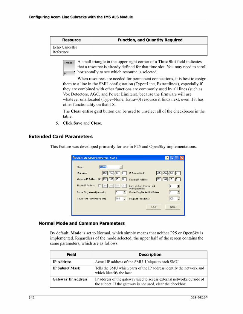
Configuring Acom Line Subracks with the IMS ALS Module
142 025-9529P
A small triangle in the upper right corner of a Time Slot field indicates that a resource is already defined for that time slot. You may need to scroll horizontally to see which resource is selected.
When resources are needed for permanent connections, it is best to assign them to a line in the SMU configuration (Type=Line, Extra=line#), especially if they are combined with other functions are commonly used by all lines (such as Vox Detectors, AGC, and Power Limiters), because the firmware will use whatever unallocated (Type=None, Extra=0) resource it finds next, even if it has other functionality on that TS.
The Clear entire grid button can be used to unselect all of the checkboxes in the table.
5. Click Save and Close.
Extended Card Parameters
This feature was developed primarily for use in P25 and OpenSky implementations.
Normal Mode and Common Parameters
By default, Mode is set to Normal, which simply means that neither P25 or OpenSky is implemented. Regardless of the mode selected, the upper half of the screen contains the same parameters, which are as follows:
Echo Canceller Reference
Resource Function, and Quantity Required
Field Description
IP Address Actual IP address of the SMU. Unique to each SMU.
IP Subnet Mask Tells the SMU which parts of the IP address identify the network and which identify the host.
Gateway IP Address IP address of the gateway used to access external networks outside of the subnet. If the gateway is not used, clear the checkbox.
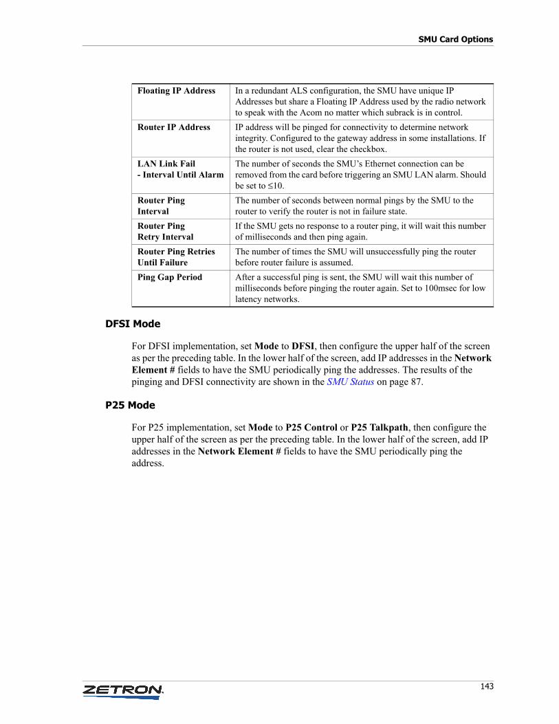
143
SMU Card Options
DFSI Mode
For DFSI implementation, set Mode to DFSI, then configure the upper half of the screen as per the preceding table. In the lower half of the screen, add IP addresses in the Network Element # fields to have the SMU periodically ping the addresses. The results of the pinging and DFSI connectivity are shown in the SMU Status on page 87.
P25 Mode
For P25 implementation, set Mode to P25 Control or P25 Talkpath, then configure the upper half of the screen as per the preceding table. In the lower half of the screen, add IP addresses in the Network Element # fields to have the SMU periodically ping the address.
Floating IP Address In a redundant ALS configuration, the SMU have unique IP Addresses but share a Floating IP Address used by the radio network to speak with the Acom no matter which subrack is in control.
Router IP Address IP address will be pinged for connectivity to determine network integrity. Configured to the gateway address in some installations. If the router is not used, clear the checkbox.
LAN Link Fail - Interval Until Alarm
The number of seconds the SMU’s Ethernet connection can be removed from the card before triggering an SMU LAN alarm. Should be set to ≤10.
Router Ping Interval
The number of seconds between normal pings by the SMU to the router to verify the router is not in failure state.
Router Ping Retry Interval
If the SMU gets no response to a router ping, it will wait this number of milliseconds and then ping again.
Router Ping Retries Until Failure
The number of times the SMU will unsuccessfully ping the router before router failure is assumed.
Ping Gap Period After a successful ping is sent, the SMU will wait this number of milliseconds before pinging the router again. Set to 100msec for low latency networks.
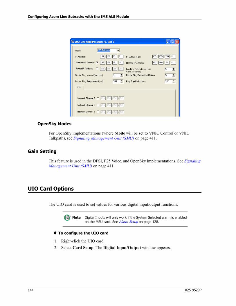
Configuring Acom Line Subracks with the IMS ALS Module
144 025-9529P
OpenSky Modes
For OpenSky implementations (where Mode will be set to VNIC Control or VNIC Talkpath), see Signaling Management Unit (SMU) on page 411.
Gain Setting
This feature is used in the DFSI, P25 Voice, and OpenSky implementations. See Signaling Management Unit (SMU) on page 411.
UIO Card Options
The UIO card is used to set values for various digital input/output functions.
♦ To configure the UIO card
1. Right-click the UIO card.
2. Select Card Setup. The Digital Input/Output window appears.
Note Digital Inputs will only work if the System Selected alarm is enabled on the MSU card. See Alarm Setup on page 128.
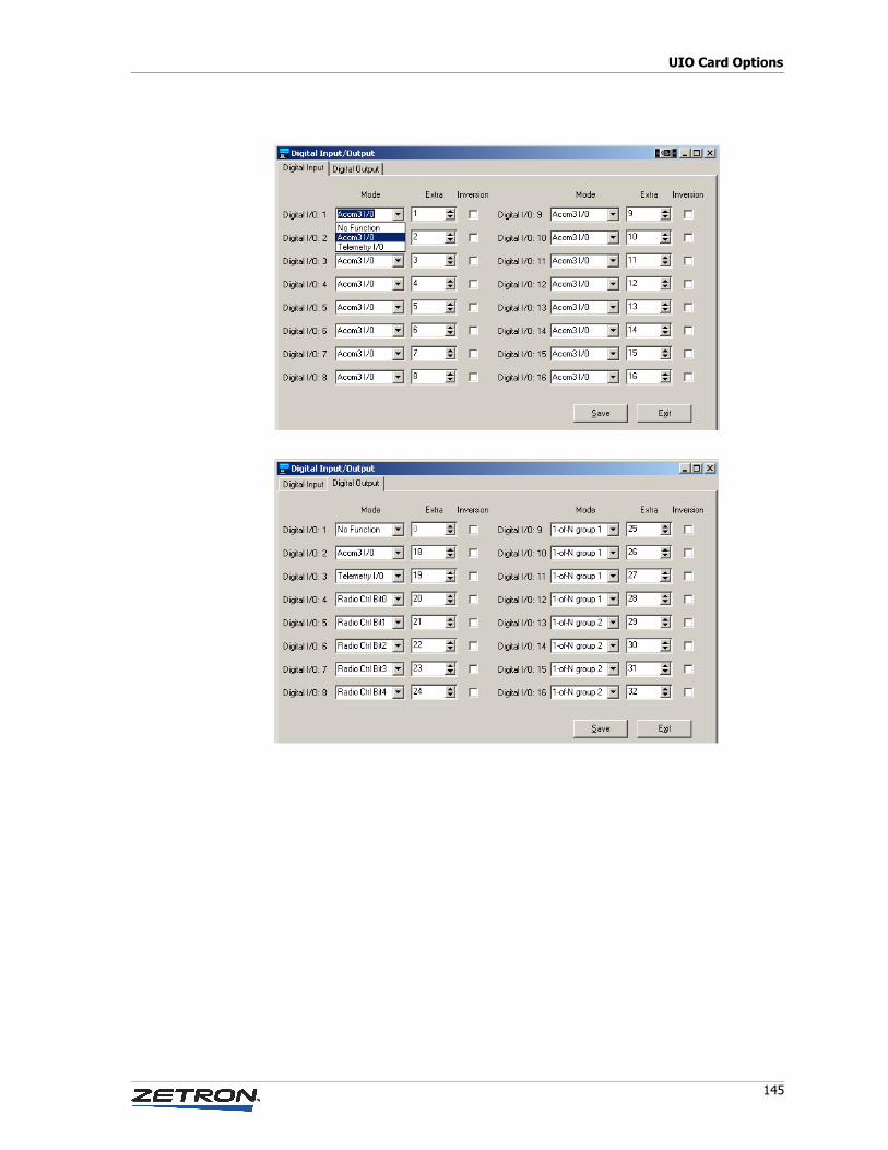
145
UIO Card Options
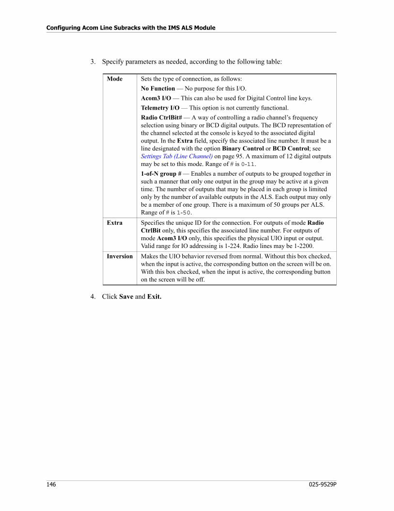
Configuring Acom Line Subracks with the IMS ALS Module
146 025-9529P
3. Specify parameters as needed, according to the following table:
4. Click Save and Exit.
Mode Sets the type of connection, as follows:
No Function — No purpose for this I/O.
Acom3 I/O — This can also be used for Digital Control line keys.
Telemetry I/O — This option is not currently functional.
Radio CtrlBit# — A way of controlling a radio channel’s frequency selection using binary or BCD digital outputs. The BCD representation of the channel selected at the console is keyed to the associated digital output. In the Extra field, specify the associated line number. It must be a line designated with the option Binary Control or BCD Control; see Settings Tab (Line Channel) on page 95. A maximum of 12 digital outputs may be set to this mode. Range of # is 0-11.
1-of-N group # — Enables a number of outputs to be grouped together in such a manner that only one output in the group may be active at a given time. The number of outputs that may be placed in each group is limited only by the number of available outputs in the ALS. Each output may only be a member of one group. There is a maximum of 50 groups per ALS. Range of # is 1-50.
Extra Specifies the unique ID for the connection. For outputs of mode Radio CtrlBit only, this specifies the associated line number. For outputs of mode Acom3 I/O only, this specifies the physical UIO input or output. Valid range for IO addressing is 1-224. Radio lines may be 1-2200.
Inversion Makes the UIO behavior reversed from normal. Without this box checked, when the input is active, the corresponding button on the screen will be on. With this box checked, when the input is active, the corresponding button on the screen will be off.
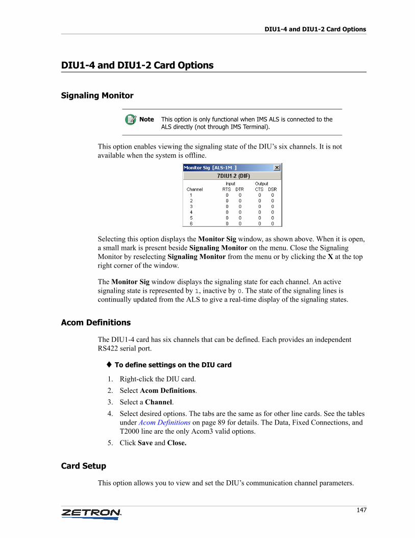
147
DIU1-4 and DIU1-2 Card Options
DIU1-4 and DIU1-2 Card Options
Signaling Monitor
This option enables viewing the signaling state of the DIU’s six channels. It is not available when the system is offline.
Selecting this option displays the Monitor Sig window, as shown above. When it is open, a small mark is present beside Signaling Monitor on the menu. Close the Signaling Monitor by reselecting Signaling Monitor from the menu or by clicking the X at the top right corner of the window.
The Monitor Sig window displays the signaling state for each channel. An active signaling state is represented by 1, inactive by 0. The state of the signaling lines is continually updated from the ALS to give a real-time display of the signaling states.
Acom Definitions
The DIU1-4 card has six channels that can be defined. Each provides an independent RS422 serial port.
♦ To define settings on the DIU card
1. Right-click the DIU card.
2. Select Acom Definitions.
3. Select a Channel.
4. Select desired options. The tabs are the same as for other line cards. See the tables under Acom Definitions on page 89 for details. The Data, Fixed Connections, and T2000 line are the only Acom3 valid options.
5. Click Save and Close.
Card Setup
This option allows you to view and set the DIU’s communication channel parameters.
Note This option is only functional when IMS ALS is connected to the ALS directly (not through IMS Terminal).
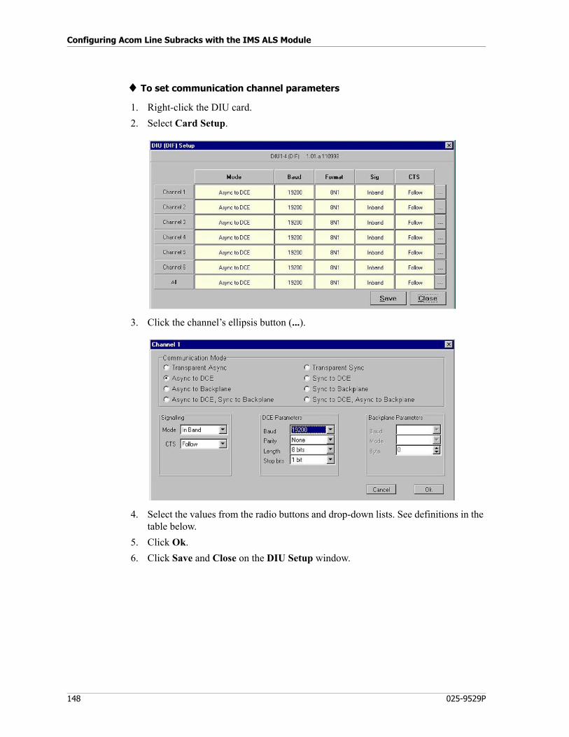
Configuring Acom Line Subracks with the IMS ALS Module
148 025-9529P
♦ To set communication channel parameters
1. Right-click the DIU card.
2. Select Card Setup.
3. Click the channel’s ellipsis button (...).
4. Select the values from the radio buttons and drop-down lists. See definitions in the table below.
5. Click Ok.
6. Click Save and Close on the DIU Setup window.
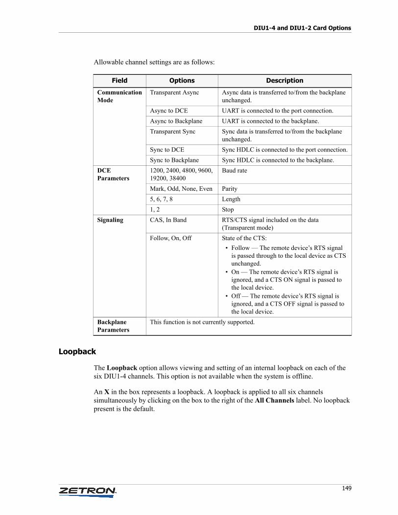
149
DIU1-4 and DIU1-2 Card Options
Allowable channel settings are as follows:
Loopback
The Loopback option allows viewing and setting of an internal loopback on each of the six DIU1-4 channels. This option is not available when the system is offline.
An X in the box represents a loopback. A loopback is applied to all six channels simultaneously by clicking on the box to the right of the All Channels label. No loopback present is the default.
Field Options Description
CommunicationMode
Transparent Async Async data is transferred to/from the backplane unchanged.
Async to DCE UART is connected to the port connection.
Async to Backplane UART is connected to the backplane.
Transparent Sync Sync data is transferred to/from the backplane unchanged.
Sync to DCE Sync HDLC is connected to the port connection.
Sync to Backplane Sync HDLC is connected to the backplane.
DCE Parameters
1200, 2400, 4800, 9600, 19200, 38400
Baud rate
Mark, Odd, None, Even Parity
5, 6, 7, 8 Length
1, 2 Stop
Signaling CAS, In Band RTS/CTS signal included on the data (Transparent mode)
Follow, On, Off State of the CTS:
• Follow — The remote device’s RTS signal is passed through to the local device as CTS unchanged.
• On — The remote device’s RTS signal is ignored, and a CTS ON signal is passed to the local device.
• Off — The remote device’s RTS signal is ignored, and a CTS OFF signal is passed to the local device.
Backplane Parameters
This function is not currently supported.
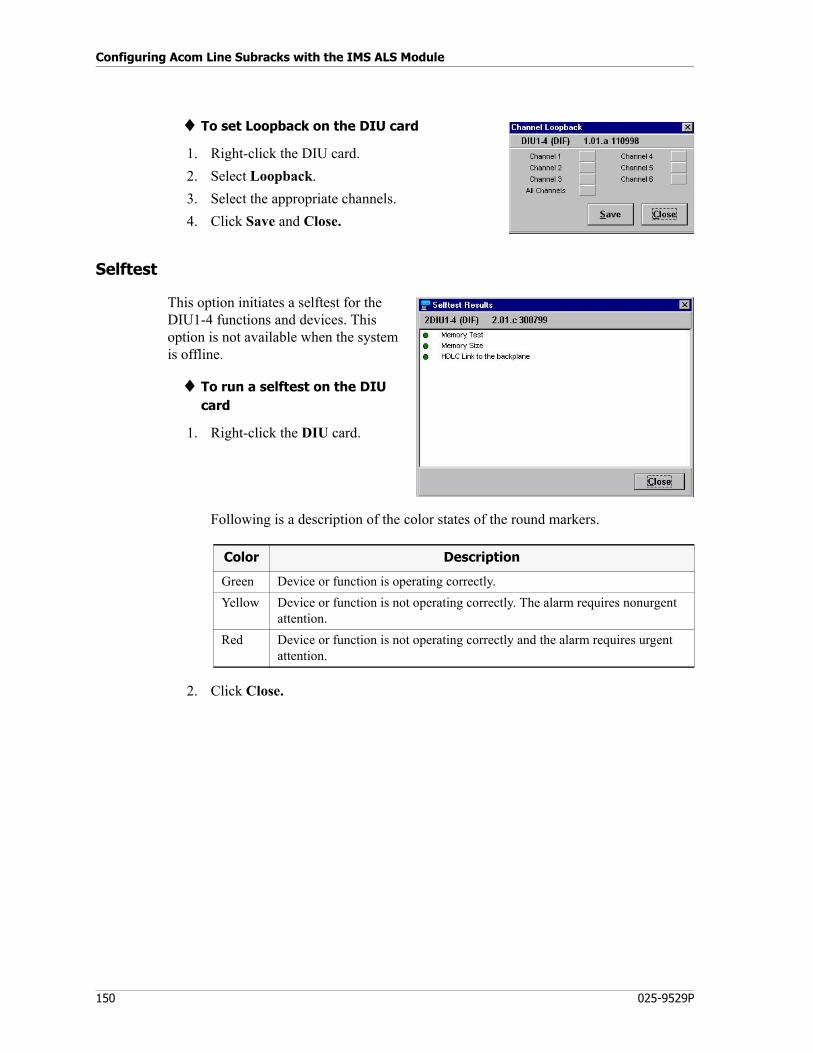
Configuring Acom Line Subracks with the IMS ALS Module
150 025-9529P
♦ To set Loopback on the DIU card
1. Right-click the DIU card.
2. Select Loopback.
3. Select the appropriate channels.
4. Click Save and Close.
Selftest
This option initiates a selftest for the DIU1-4 functions and devices. This option is not available when the system is offline.
♦ To run a selftest on the DIU card
1. Right-click the DIU card.
Following is a description of the color states of the round markers.
2. Click Close.
Color Description
Green Device or function is operating correctly.
Yellow Device or function is not operating correctly. The alarm requires nonurgent attention.
Red Device or function is not operating correctly and the alarm requires urgent attention.
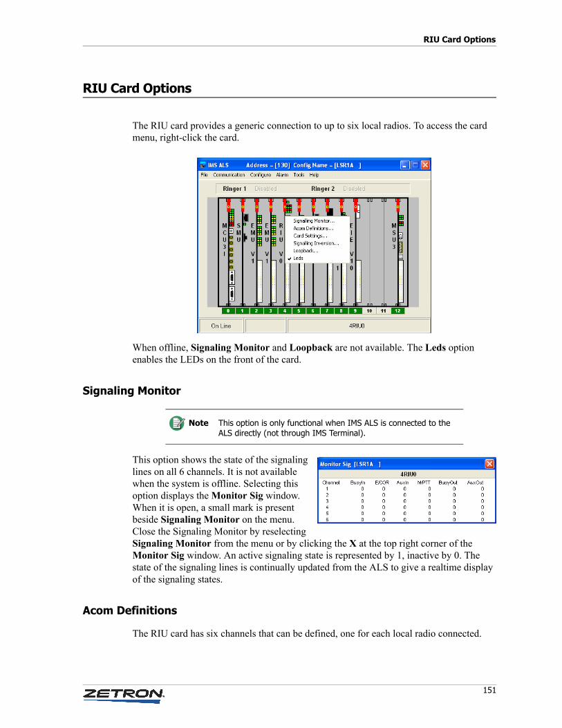
151
RIU Card Options
RIU Card Options
The RIU card provides a generic connection to up to six local radios. To access the card menu, right-click the card.
When offline, Signaling Monitor and Loopback are not available. The Leds option enables the LEDs on the front of the card.
Signaling Monitor
This option shows the state of the signaling lines on all 6 channels. It is not available when the system is offline. Selecting this option displays the Monitor Sig window. When it is open, a small mark is present beside Signaling Monitor on the menu. Close the Signaling Monitor by reselecting Signaling Monitor from the menu or by clicking the X at the top right corner of the Monitor Sig window. An active signaling state is represented by 1, inactive by 0. The state of the signaling lines is continually updated from the ALS to give a realtime display of the signaling states.
Acom Definitions
The RIU card has six channels that can be defined, one for each local radio connected.
Note This option is only functional when IMS ALS is connected to the ALS directly (not through IMS Terminal).
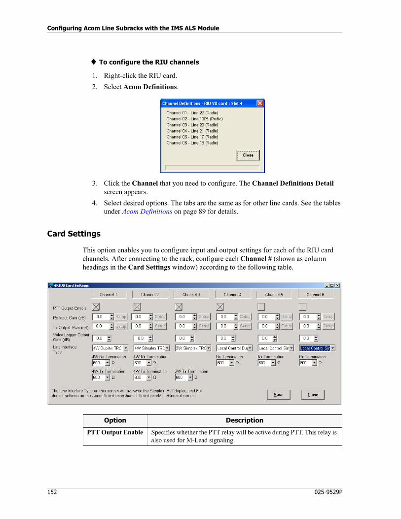
Configuring Acom Line Subracks with the IMS ALS Module
152 025-9529P
♦ To configure the RIU channels
1. Right-click the RIU card.
2. Select Acom Definitions.
3. Click the Channel that you need to configure. The Channel Definitions Detail screen appears.
4. Select desired options. The tabs are the same as for other line cards. See the tables under Acom Definitions on page 89 for details.
Card Settings
This option enables you to configure input and output settings for each of the RIU card channels. After connecting to the rack, configure each Channel # (shown as column headings in the Card Settings window) according to the following table.
Option Description
PTT Output Enable Specifies whether the PTT relay will be active during PTT. This relay is also used for M-Lead signaling.
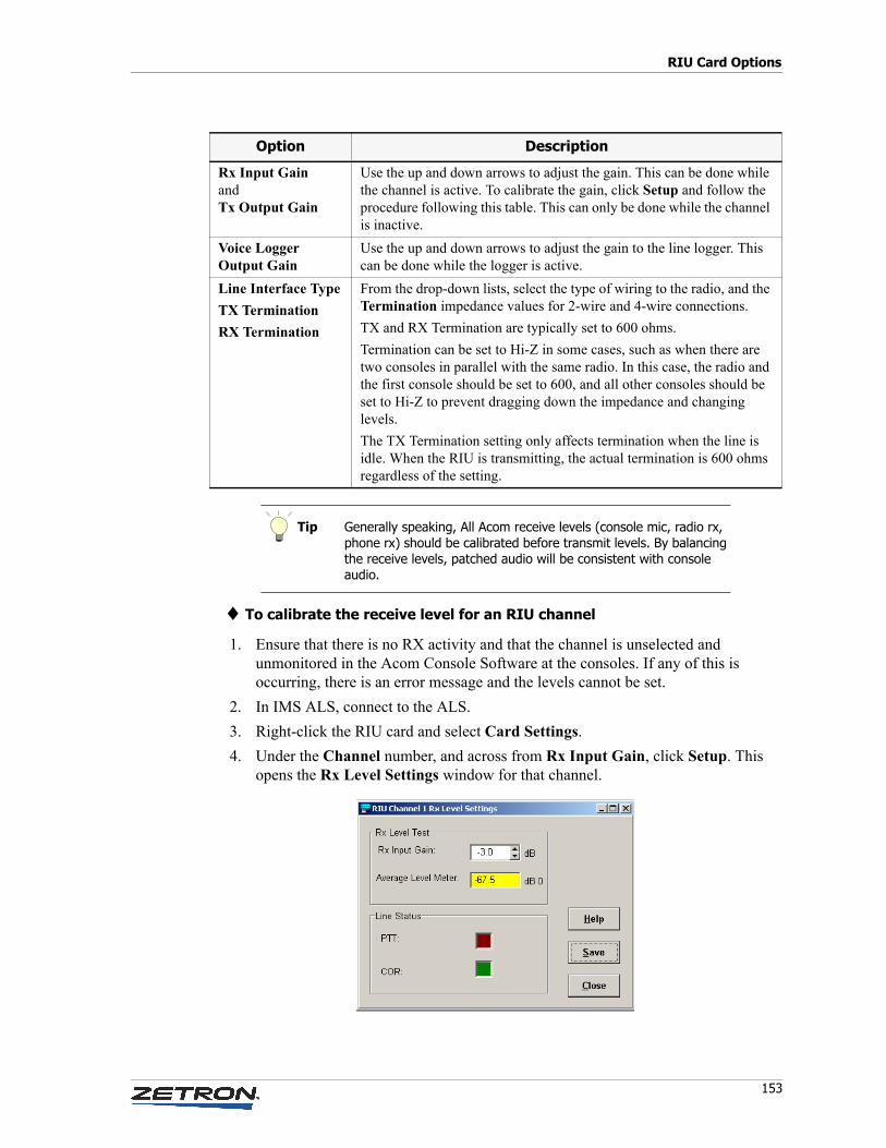
153
RIU Card Options
♦ To calibrate the receive level for an RIU channel
1. Ensure that there is no RX activity and that the channel is unselected and unmonitored in the Acom Console Software at the consoles. If any of this is occurring, there is an error message and the levels cannot be set.
2. In IMS ALS, connect to the ALS.
3. Right-click the RIU card and select Card Settings.
4. Under the Channel number, and across from Rx Input Gain, click Setup. This opens the Rx Level Settings window for that channel.
Rx Input GainandTx Output Gain
Use the up and down arrows to adjust the gain. This can be done while the channel is active. To calibrate the gain, click Setup and follow the procedure following this table. This can only be done while the channel is inactive.
Voice LoggerOutput Gain
Use the up and down arrows to adjust the gain to the line logger. This can be done while the logger is active.
Line Interface Type
TX Termination
RX Termination
From the drop-down lists, select the type of wiring to the radio, and the Termination impedance values for 2-wire and 4-wire connections.
TX and RX Termination are typically set to 600 ohms.
Termination can be set to Hi-Z in some cases, such as when there are two consoles in parallel with the same radio. In this case, the radio and the first console should be set to 600, and all other consoles should be set to Hi-Z to prevent dragging down the impedance and changing levels.
The TX Termination setting only affects termination when the line is idle. When the RIU is transmitting, the actual termination is 600 ohms regardless of the setting.
Tip Generally speaking, All Acom receive levels (console mic, radio rx, phone rx) should be calibrated before transmit levels. By balancing the receive levels, patched audio will be consistent with console audio.
Option Description
Configuring Acom Line Subracks with the IMS ALS Module
154 025-9529P
5. Using a communications service monitor or similar test equipment, generate a full-quieting 1-KHz test tone on the radio receive frequency, at 60% of full channel deviation (typically ± 3.0 KHz for a 25-KHz channel).
6. If you get a prompt about there being no Meter on the SMU, either click No and then define a Level Meter resource if you have an SMU (see To configure an SMU resource on page 138), or click Yes to adjust manually with no meter.
7. Under Rx Level Test, adjust the Rx Input Gain until the Average Level Meter reads as close to -7 dB 0 as you can get it (dB 0=digital signal level, with 0dB of gain at 600ohms, a 0dBm signal would read 0dB 0). The meter will update about every half second and will turn from yellow to green when the level is within the acceptable range of -6.4 to -7.6 dB 0.
8. The Line Status indicators (green for COR/VOX) should be bright when active, dark when inactive.
9. Click Save, or click Close to discard your adjustments.
♦ To calibrate the transmit level for an RIU channel
1. Do not click the Start button to generate a 1-KHz tone. Doing so causes an error message and the levels cannot be set.
2. In IMS ALS, connect to the ALS.
3. Right-click the RIU card and select Card Settings.
4. Under the Channel number, and across from Tx Output Gain, click Setup. This opens the Tx Level Settings window for that channel.
5. Using a communications service monitor or similar test equipment, monitor the radio transmit frequency.
6. Under Test Tone Generator, select the Test Tone Level to be generated on the Acom backplane, typically -7 dB 0 for 60% channel deviation but can vary based on system configuration.
7. Click Start. It will change to Step.
8. Monitoring the radio channel modulation, adjust the Tx Output Gain to achieve the desired level on the radio channel. The Step button can be used to step through various test tone frequencies.
9. If you get a prompt about there being no Selcal on the SMU, either click No and then define a Selcal Encoder resource if you have an SMU (see To configure an SMU resource on page 138), or click Yes to adjust manually with no test tones.
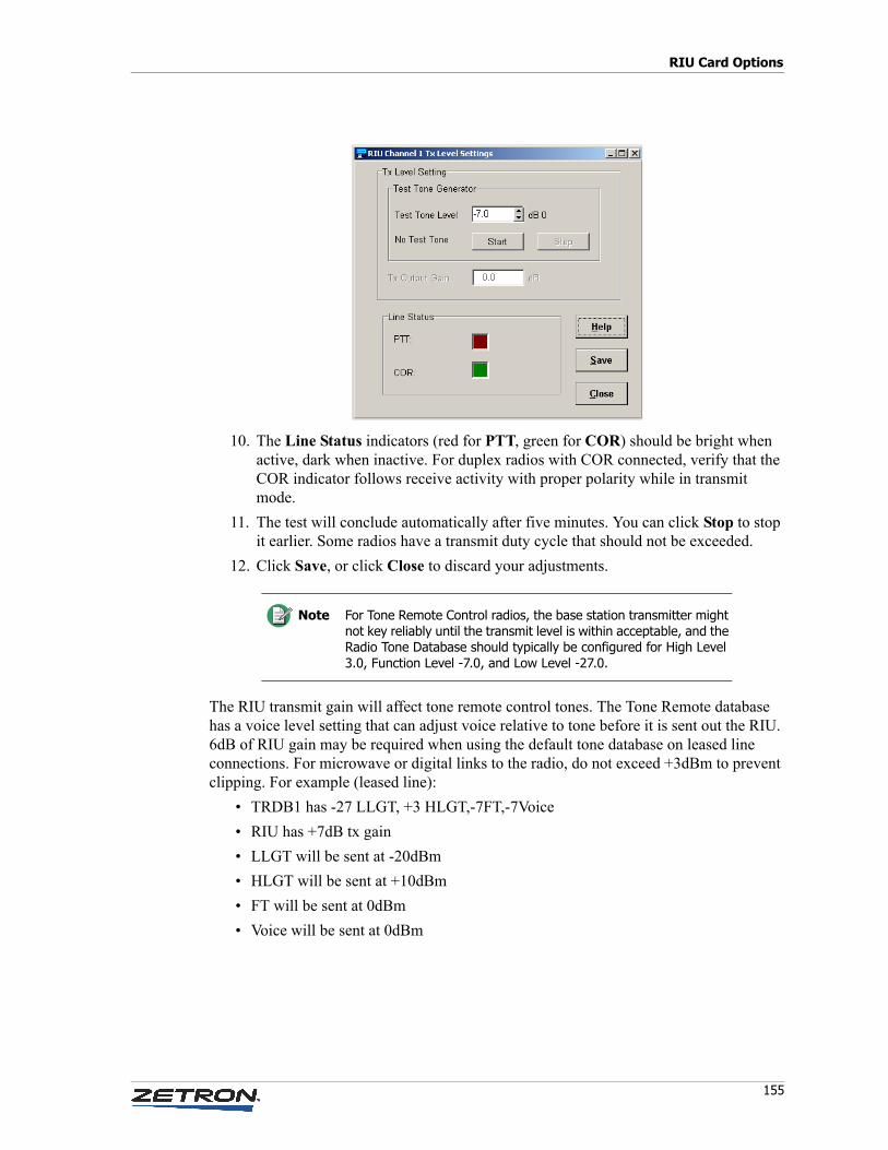
155
RIU Card Options
10. The Line Status indicators (red for PTT, green for COR) should be bright when active, dark when inactive. For duplex radios with COR connected, verify that the COR indicator follows receive activity with proper polarity while in transmit mode.
11. The test will conclude automatically after five minutes. You can click Stop to stop it earlier. Some radios have a transmit duty cycle that should not be exceeded.
12. Click Save, or click Close to discard your adjustments.
The RIU transmit gain will affect tone remote control tones. The Tone Remote database has a voice level setting that can adjust voice relative to tone before it is sent out the RIU. 6dB of RIU gain may be required when using the default tone database on leased line connections. For microwave or digital links to the radio, do not exceed +3dBm to prevent clipping. For example (leased line):
• TRDB1 has -27 LLGT, +3 HLGT,-7FT,-7Voice
• RIU has +7dB tx gain
• LLGT will be sent at -20dBm
• HLGT will be sent at +10dBm
• FT will be sent at 0dBm
• Voice will be sent at 0dBm
Note For Tone Remote Control radios, the base station transmitter might not key reliably until the transmit level is within acceptable, and the Radio Tone Database should typically be configured for High Level 3.0, Function Level -7.0, and Low Level -27.0.
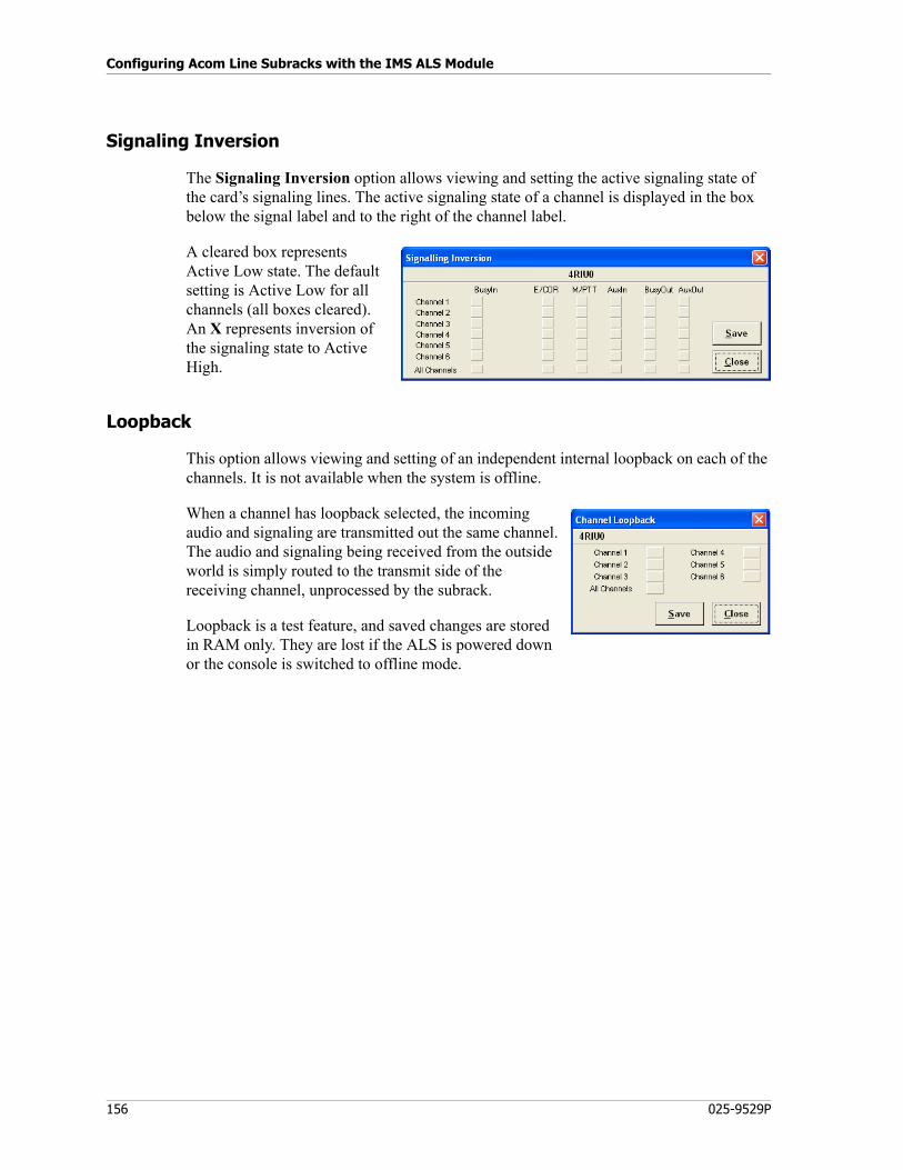
Configuring Acom Line Subracks with the IMS ALS Module
156 025-9529P
Signaling Inversion
The Signaling Inversion option allows viewing and setting the active signaling state of the card’s signaling lines. The active signaling state of a channel is displayed in the box below the signal label and to the right of the channel label.
A cleared box represents Active Low state. The default setting is Active Low for all channels (all boxes cleared). An X represents inversion of the signaling state to Active High.
Loopback
This option allows viewing and setting of an independent internal loopback on each of the channels. It is not available when the system is offline.
When a channel has loopback selected, the incoming audio and signaling are transmitted out the same channel. The audio and signaling being received from the outside world is simply routed to the transmit side of the receiving channel, unprocessed by the subrack.
Loopback is a test feature, and saved changes are stored in RAM only. They are lost if the ALS is powered down or the console is switched to offline mode.
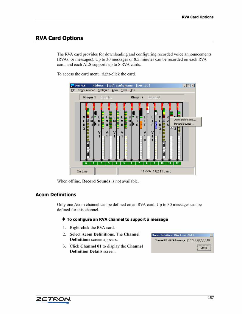
157
RVA Card Options
RVA Card Options
The RVA card provides for downloading and configuring recorded voice announcements (RVAs, or messages). Up to 30 messages or 8.5 minutes can be recorded on each RVA card, and each ALS supports up to 8 RVA cards.
To access the card menu, right-click the card.
When offline, Record Sounds is not available.
Acom Definitions
Only one Acom channel can be defined on an RVA card. Up to 30 messages can be defined for this channel.
♦ To configure an RVA channel to support a message
1. Right-click the RVA card.
2. Select Acom Definitions. The Channel Definitions screen appears.
3. Click Channel 01 to display the Channel Definition Details screen.
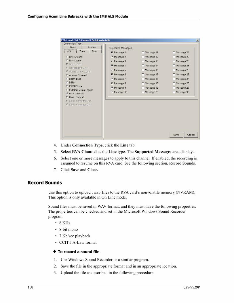
Configuring Acom Line Subracks with the IMS ALS Module
158 025-9529P
4. Under Connection Type, click the Line tab.
5. Select RVA Channel as the Line type. The Supported Messages area displays.
6. Select one or more messages to apply to this channel. If enabled, the recording is assumed to resume on this RVA card. See the following section, Record Sounds.
7. Click Save and Close.
Record Sounds
Use this option to upload .wav files to the RVA card’s nonvolatile memory (NVRAM). This option is only available in On Line mode.
Sound files must be saved in WAV format, and they must have the following properties. The properties can be checked and set in the Microsoft Windows Sound Recorder program.
• 8 KHz
• 8-bit mono
• 7 Kb/sec playback
• CCITT A-Law format
♦ To record a sound file
1. Use Windows Sound Recorder or a similar program.
2. Save the file in the appropriate format and in an appropriate location.
3. Upload the file as described in the following procedure.
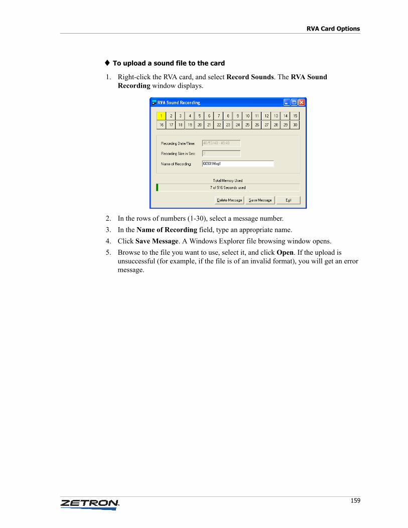
159
RVA Card Options
♦ To upload a sound file to the card
1. Right-click the RVA card, and select Record Sounds. The RVA Sound Recording window displays.
2. In the rows of numbers (1-30), select a message number.
3. In the Name of Recording field, type an appropriate name.
4. Click Save Message. A Windows Explorer file browsing window opens.
5. Browse to the file you want to use, select it, and click Open. If the upload is unsuccessful (for example, if the file is of an invalid format), you will get an error message.
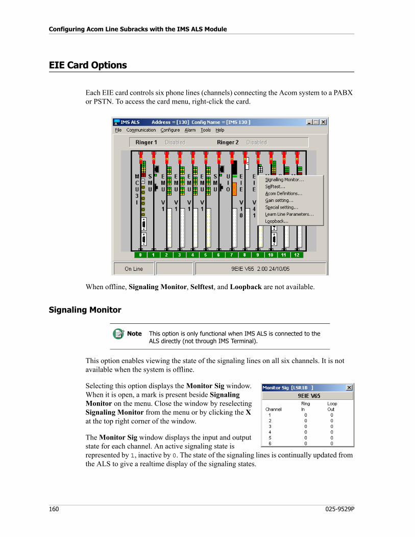
Configuring Acom Line Subracks with the IMS ALS Module
160 025-9529P
EIE Card Options
Each EIE card controls six phone lines (channels) connecting the Acom system to a PABX or PSTN. To access the card menu, right-click the card.
When offline, Signaling Monitor, Selftest, and Loopback are not available.
Signaling Monitor
This option enables viewing the state of the signaling lines on all six channels. It is not available when the system is offline.
Selecting this option displays the Monitor Sig window. When it is open, a mark is present beside Signaling Monitor on the menu. Close the window by reselecting Signaling Monitor from the menu or by clicking the X at the top right corner of the window.
The Monitor Sig window displays the input and output state for each channel. An active signaling state is represented by 1, inactive by 0. The state of the signaling lines is continually updated from the ALS to give a realtime display of the signaling states.
Note This option is only functional when IMS ALS is connected to the ALS directly (not through IMS Terminal).
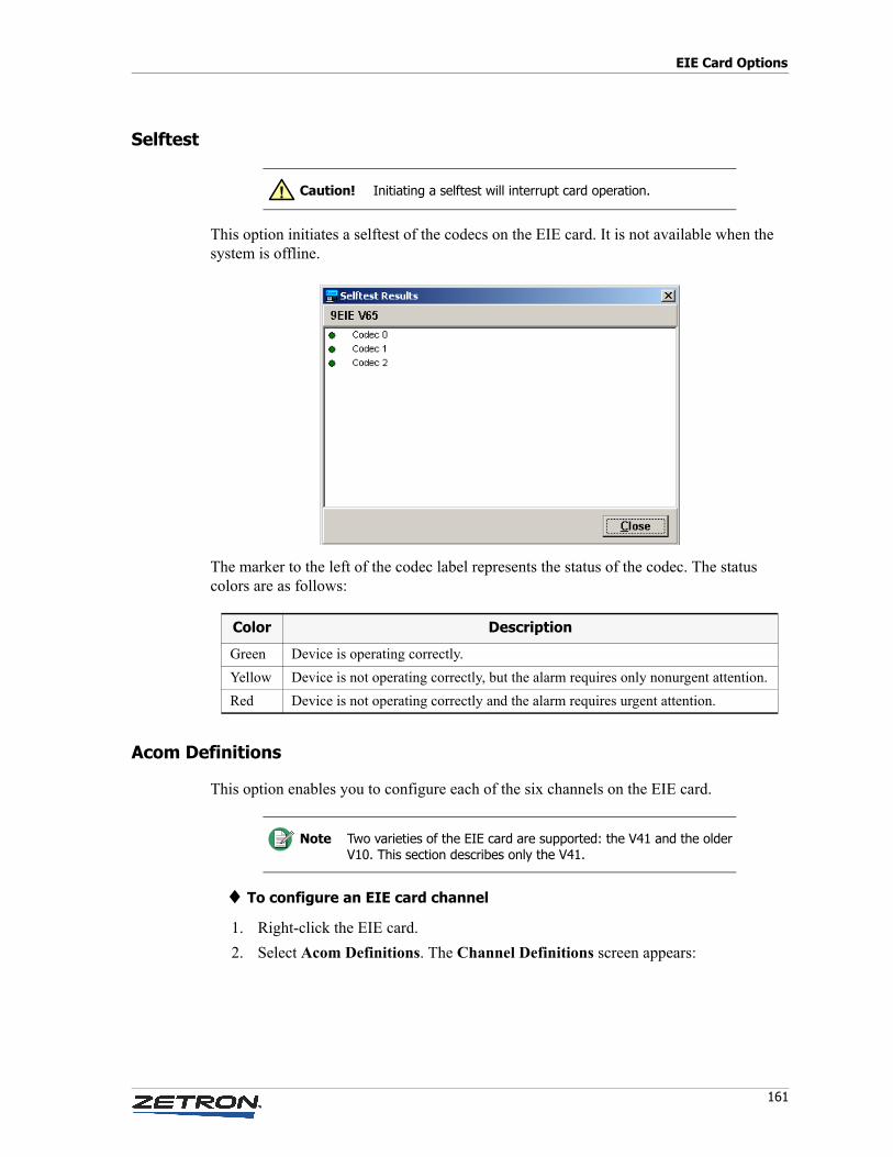
161
EIE Card Options
Selftest
This option initiates a selftest of the codecs on the EIE card. It is not available when the system is offline.
The marker to the left of the codec label represents the status of the codec. The status colors are as follows:
Acom Definitions
This option enables you to configure each of the six channels on the EIE card.
♦ To configure an EIE card channel
1. Right-click the EIE card.
2. Select Acom Definitions. The Channel Definitions screen appears:
Caution! Initiating a selftest will interrupt card operation.!
Color Description
Green Device is operating correctly.
Yellow Device is not operating correctly, but the alarm requires only nonurgent attention.
Red Device is not operating correctly and the alarm requires urgent attention.
Note Two varieties of the EIE card are supported: the V41 and the older V10. This section describes only the V41.
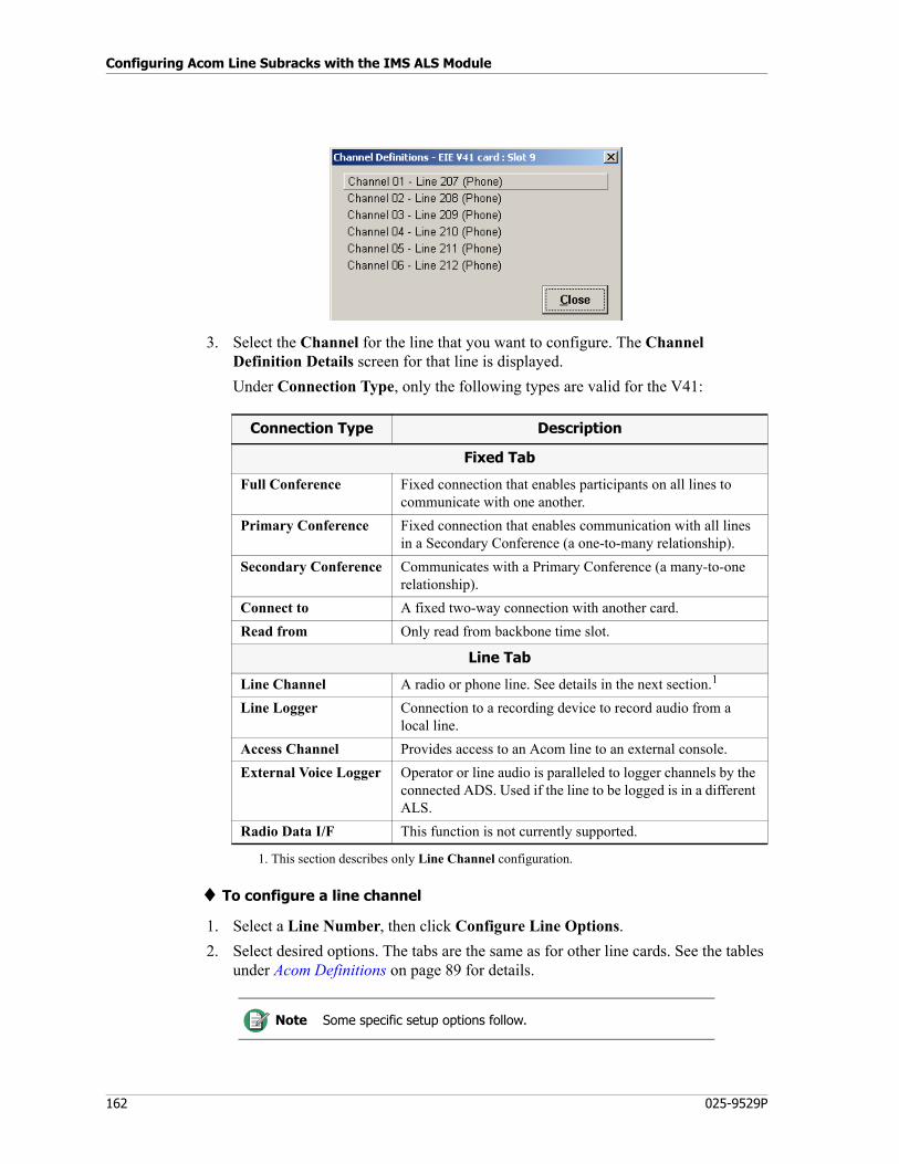
Configuring Acom Line Subracks with the IMS ALS Module
162 025-9529P
3. Select the Channel for the line that you want to configure. The Channel Definition Details screen for that line is displayed.
Under Connection Type, only the following types are valid for the V41:
♦ To configure a line channel
1. Select a Line Number, then click Configure Line Options.
2. Select desired options. The tabs are the same as for other line cards. See the tables under Acom Definitions on page 89 for details.
Connection Type Description
Fixed Tab
Full Conference Fixed connection that enables participants on all lines to communicate with one another.
Primary Conference Fixed connection that enables communication with all lines in a Secondary Conference (a one-to-many relationship).
Secondary Conference Communicates with a Primary Conference (a many-to-one relationship).
Connect to A fixed two-way connection with another card.
Read from Only read from backbone time slot.
Line Tab
Line Channel A radio or phone line. See details in the next section.1
1. This section describes only Line Channel configuration.
Line Logger Connection to a recording device to record audio from a local line.
Access Channel Provides access to an Acom line to an external console.
External Voice Logger Operator or line audio is paralleled to logger channels by the connected ADS. Used if the line to be logged is in a different ALS.
Radio Data I/F This function is not currently supported.
Note Some specific setup options follow.
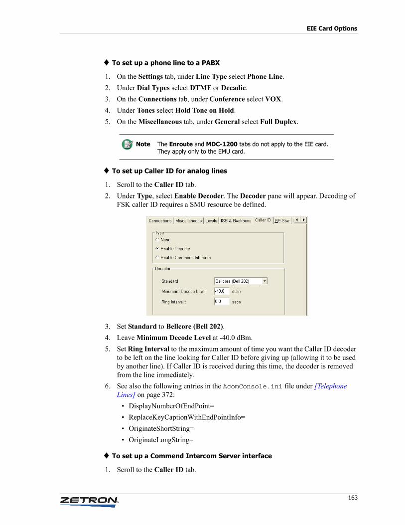
163
EIE Card Options
♦ To set up a phone line to a PABX
1. On the Settings tab, under Line Type select Phone Line.
2. Under Dial Types select DTMF or Decadic.
3. On the Connections tab, under Conference select VOX.
4. Under Tones select Hold Tone on Hold.
5. On the Miscellaneous tab, under General select Full Duplex.
♦ To set up Caller ID for analog lines
1. Scroll to the Caller ID tab.
2. Under Type, select Enable Decoder. The Decoder pane will appear. Decoding of FSK caller ID requires a SMU resource be defined.
3. Set Standard to Bellcore (Bell 202).
4. Leave Minimum Decode Level at -40.0 dBm.
5. Set Ring Interval to the maximum amount of time you want the Caller ID decoder to be left on the line looking for Caller ID before giving up (allowing it to be used by another line). If Caller ID is received during this time, the decoder is removed from the line immediately.
6. See also the following entries in the AcomConsole.ini file under [Telephone Lines] on page 372:
• DisplayNumberOfEndPoint=
• ReplaceKeyCaptionWithEndPointInfo=
• OriginateShortString=
• OriginateLongString=
♦ To set up a Commend Intercom Server interface
1. Scroll to the Caller ID tab.
Note The Enroute and MDC-1200 tabs do not apply to the EIE card. They apply only to the EMU card.
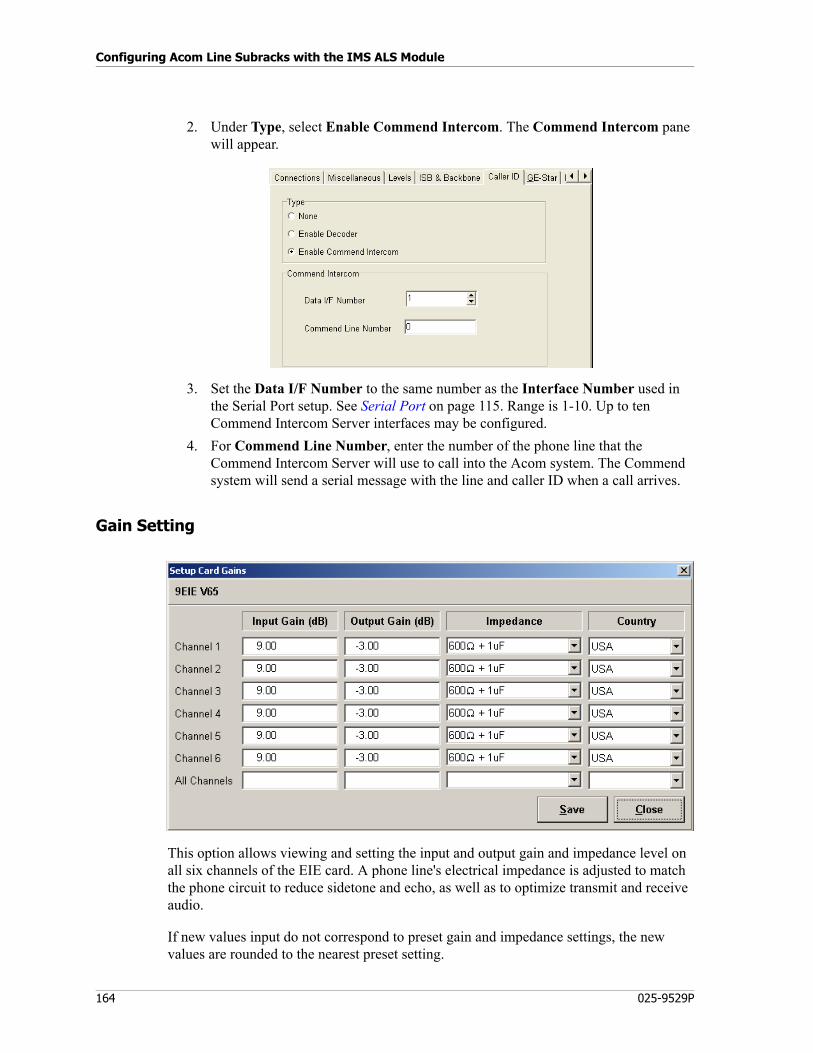
Configuring Acom Line Subracks with the IMS ALS Module
164 025-9529P
2. Under Type, select Enable Commend Intercom. The Commend Intercom pane will appear.
3. Set the Data I/F Number to the same number as the Interface Number used in the Serial Port setup. See Serial Port on page 115. Range is 1-10. Up to ten Commend Intercom Server interfaces may be configured.
4. For Commend Line Number, enter the number of the phone line that the Commend Intercom Server will use to call into the Acom system. The Commend system will send a serial message with the line and caller ID when a call arrives.
Gain Setting
This option allows viewing and setting the input and output gain and impedance level on all six channels of the EIE card. A phone line's electrical impedance is adjusted to match the phone circuit to reduce sidetone and echo, as well as to optimize transmit and receive audio.
If new values input do not correspond to preset gain and impedance settings, the new values are rounded to the nearest preset setting.
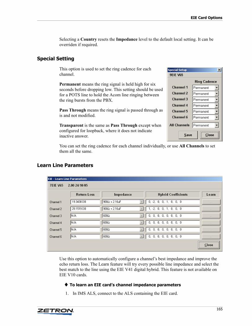
165
EIE Card Options
Selecting a Country resets the Impedance level to the default local setting. It can be overriden if required.
Special Setting
This option is used to set the ring cadence for each channel.
Permanent means the ring signal is held high for six seconds before dropping low. This setting should be used for a POTS line to hold the Acom line ringing between the ring bursts from the PBX.
Pass Through means the ring signal is passed through as is and not modified.
Transparent is the same as Pass Through except when configured for loopback, where it does not indicate inactive answer.
You can set the ring cadence for each channel individually, or use All Channels to set them all the same.
Learn Line Parameters
Use this option to automatically configure a channel’s best impedance and improve the echo return loss. The Learn feature will try every possible line impedance and select the best match to the line using the EIE V41 digital hybrid. This feature is not available on EIE V10 cards.
♦ To learn an EIE card’s channel impedance parameters
1. In IMS ALS, connect to the ALS containing the EIE card.
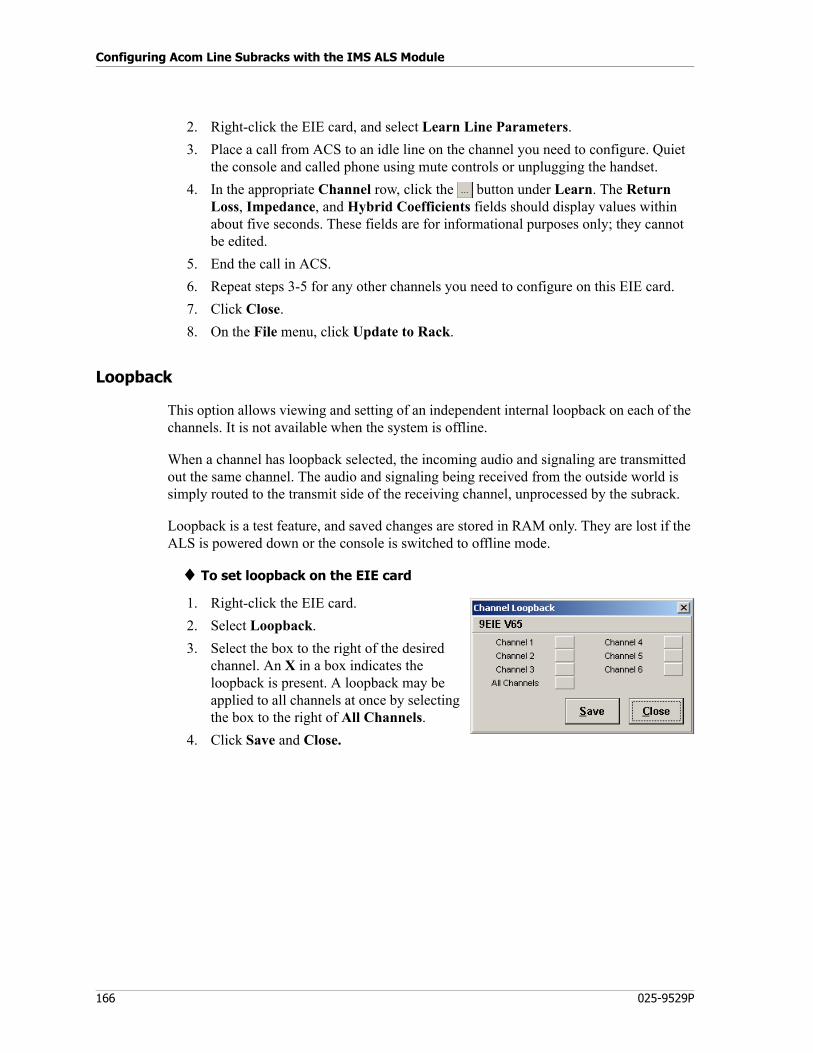
Configuring Acom Line Subracks with the IMS ALS Module
166 025-9529P
2. Right-click the EIE card, and select Learn Line Parameters.
3. Place a call from ACS to an idle line on the channel you need to configure. Quiet the console and called phone using mute controls or unplugging the handset.
4. In the appropriate Channel row, click the button under Learn. The Return Loss, Impedance, and Hybrid Coefficients fields should display values within about five seconds. These fields are for informational purposes only; they cannot be edited.
5. End the call in ACS.
6. Repeat steps 3-5 for any other channels you need to configure on this EIE card.
7. Click Close.
8. On the File menu, click Update to Rack.
Loopback
This option allows viewing and setting of an independent internal loopback on each of the channels. It is not available when the system is offline.
When a channel has loopback selected, the incoming audio and signaling are transmitted out the same channel. The audio and signaling being received from the outside world is simply routed to the transmit side of the receiving channel, unprocessed by the subrack.
Loopback is a test feature, and saved changes are stored in RAM only. They are lost if the ALS is powered down or the console is switched to offline mode.
♦ To set loopback on the EIE card
1. Right-click the EIE card.
2. Select Loopback.
3. Select the box to the right of the desired channel. An X in a box indicates the loopback is present. A loopback may be applied to all channels at once by selecting the box to the right of All Channels.
4. Click Save and Close.
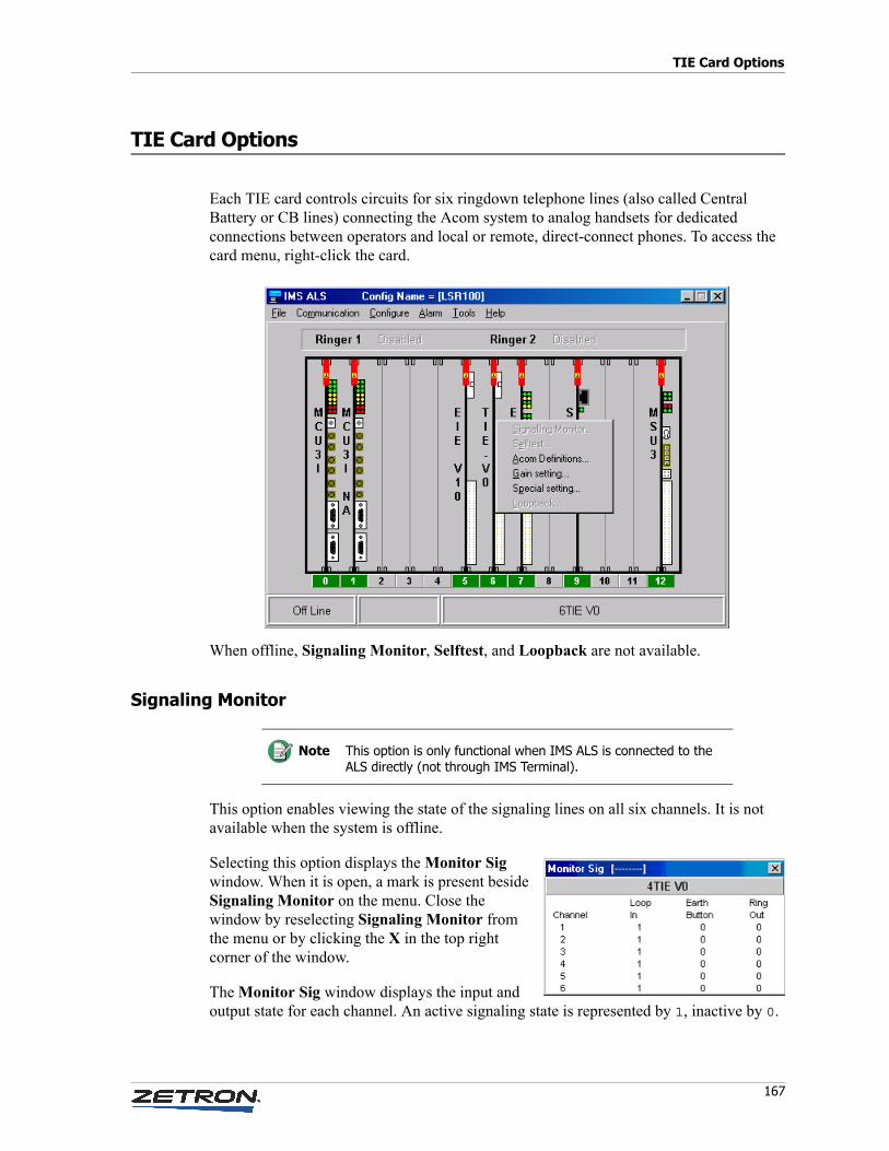
167
TIE Card Options
TIE Card Options
Each TIE card controls circuits for six ringdown telephone lines (also called Central Battery or CB lines) connecting the Acom system to analog handsets for dedicated connections between operators and local or remote, direct-connect phones. To access the card menu, right-click the card.
When offline, Signaling Monitor, Selftest, and Loopback are not available.
Signaling Monitor
This option enables viewing the state of the signaling lines on all six channels. It is not available when the system is offline.
Selecting this option displays the Monitor Sig window. When it is open, a mark is present beside Signaling Monitor on the menu. Close the window by reselecting Signaling Monitor from the menu or by clicking the X in the top right corner of the window.
The Monitor Sig window displays the input and output state for each channel. An active signaling state is represented by 1, inactive by 0.
Note This option is only functional when IMS ALS is connected to the ALS directly (not through IMS Terminal).
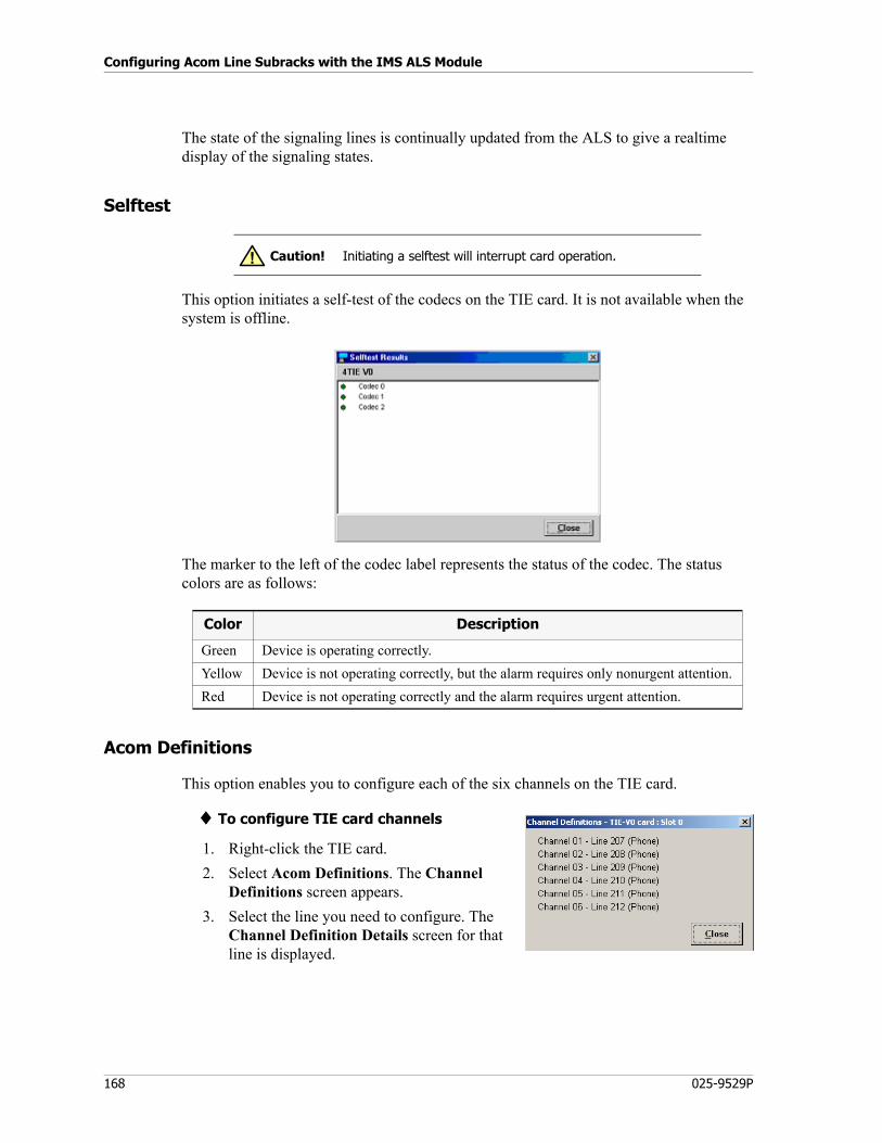
Configuring Acom Line Subracks with the IMS ALS Module
168 025-9529P
The state of the signaling lines is continually updated from the ALS to give a realtime display of the signaling states.
Selftest
This option initiates a self-test of the codecs on the TIE card. It is not available when the system is offline.
The marker to the left of the codec label represents the status of the codec. The status colors are as follows:
Acom Definitions
This option enables you to configure each of the six channels on the TIE card.
♦ To configure TIE card channels
1. Right-click the TIE card.
2. Select Acom Definitions. The Channel Definitions screen appears.
3. Select the line you need to configure. The Channel Definition Details screen for that line is displayed.
Caution! Initiating a selftest will interrupt card operation.!
Color Description
Green Device is operating correctly.
Yellow Device is not operating correctly, but the alarm requires only nonurgent attention.
Red Device is not operating correctly and the alarm requires urgent attention.
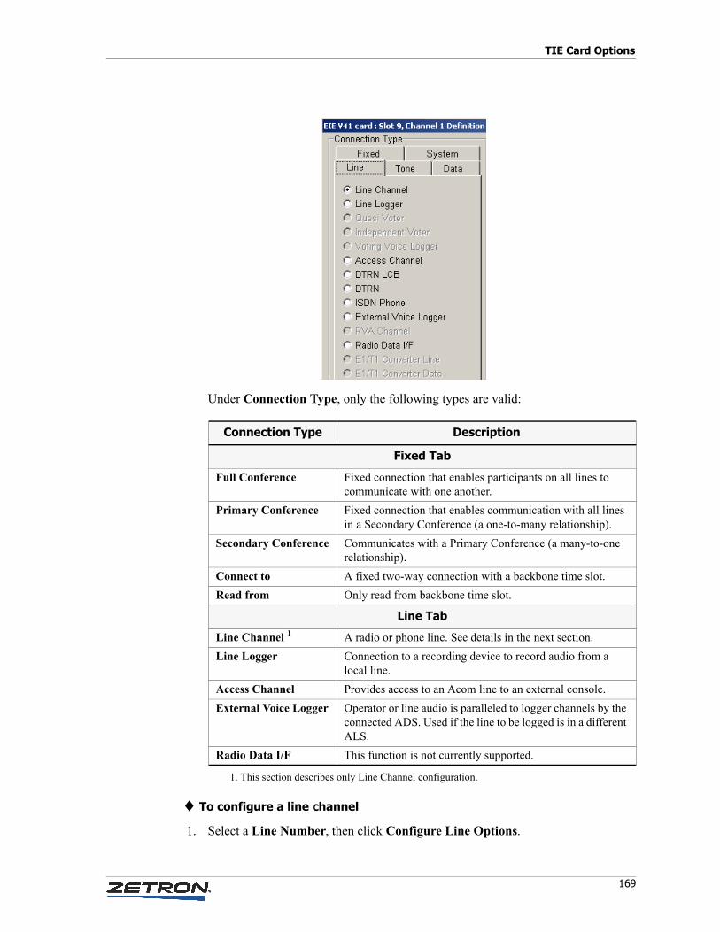
169
TIE Card Options
Under Connection Type, only the following types are valid:
♦ To configure a line channel
1. Select a Line Number, then click Configure Line Options.
Connection Type Description
Fixed Tab
Full Conference Fixed connection that enables participants on all lines to communicate with one another.
Primary Conference Fixed connection that enables communication with all lines in a Secondary Conference (a one-to-many relationship).
Secondary Conference Communicates with a Primary Conference (a many-to-one relationship).
Connect to A fixed two-way connection with a backbone time slot.
Read from Only read from backbone time slot.
Line Tab
Line Channel 1
1. This section describes only Line Channel configuration.
A radio or phone line. See details in the next section.
Line Logger Connection to a recording device to record audio from a local line.
Access Channel Provides access to an Acom line to an external console.
External Voice Logger Operator or line audio is paralleled to logger channels by the connected ADS. Used if the line to be logged is in a different ALS.
Radio Data I/F This function is not currently supported.
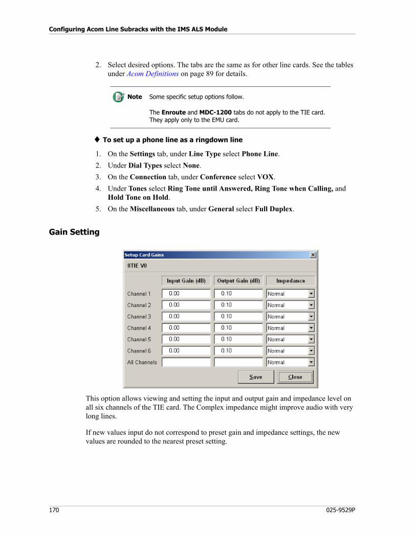
Configuring Acom Line Subracks with the IMS ALS Module
170 025-9529P
2. Select desired options. The tabs are the same as for other line cards. See the tables under Acom Definitions on page 89 for details.
♦ To set up a phone line as a ringdown line
1. On the Settings tab, under Line Type select Phone Line.
2. Under Dial Types select None.
3. On the Connection tab, under Conference select VOX.
4. Under Tones select Ring Tone until Answered, Ring Tone when Calling, and Hold Tone on Hold.
5. On the Miscellaneous tab, under General select Full Duplex.
Gain Setting
This option allows viewing and setting the input and output gain and impedance level on all six channels of the TIE card. The Complex impedance might improve audio with very long lines.
If new values input do not correspond to preset gain and impedance settings, the new values are rounded to the nearest preset setting.
Note Some specific setup options follow.
The Enroute and MDC-1200 tabs do not apply to the TIE card. They apply only to the EMU card.

171
TIE Card Options
Loopback
This option allows viewing and setting of an independent internal loopback on each of the channels. It is not available when the system is offline.
When a channel has loopback selected, the incoming audio and signaling are transmitted out the same channel. The audio and signaling being received from the outside world is simply routed to the transmit side of the receiving channel, unprocessed by the subrack.
Loopback is a test feature, and saved changes are stored in RAM only. They are lost if the ALS is powered down or the console is switched to offline mode.
♦ To set loopback on the TIE card
1. Right-click the TIE card.
2. Select Loopback.
3. Select the box to the right of the desired channel. An X in a box indicates the loopback is present. A loopback may be applied to all channels at once by selecting the box to the right of All Channels.
4. Click Save and Close.
Special Setting
This option is used to set the ring cadence and ring tone for each channel.
Pass Through — The ring signal is passed through as is and not modified.
Generate -1 through Generate -4 — The ring cadence is pulsed by the ALS until answered. The numbers 1-4 refer to the Ring Cadence Types defined. Generating ring is the most common setting for a Ringdown line. See Ring Cadence on page 77.

Configuring Acom Line Subracks with the IMS ALS Module
172 025-9529P
You can set the ring cadence and ring tone for each channel individually, or use All Channels to set them all the same.
Getting Started
173
Configuring Acom DS3 Subracks with the IMS ADS Module
This chapter describes the ADS module of the Integrated Management System (IMS), software designed for configuring and managing Acom DS3 Switches (ADSes) that are part of an Acom system.
In this chapter:
• Getting Started on page 173
• Managing Configurations (File Menu) on page 178
• Communicating with the ADS (Communication Menu) on page 180
• Configuring ADS Parameters (Configure Menu) on page 183
• Alarm Menu on page 200
• Tools Menu on page 205
• DCU Card Options on page 211
• EIU Card Options on page 215
• MCU4 Card Options on page 219
Getting Started
Using IMS ADS with or without IMS Terminal
IMS ADS may be operated in conjunction with IMS Terminal or as an independent module. If it is used with IMS Terminal, you must copy the IMS_ADS.EXE file into the IMS Terminal folder and register IMS ADS with IMS Terminal. To register, run IMS Terminal Config, check the box labeled ADS, and click OK.
If run with IMS Terminal, IMS ADS can be run from IMS Terminal whether IMS Terminal is in standalone mode, connected directly to a hub, or on a network. When IMS
Configuring Acom DS3 Subracks with the IMS ADS Module
174 025-9529P
Terminal is in standalone mode, IMS ADS is run by clicking ADS. When IMS Terminal is not in standalone mode, a Device Marker must be defined on one of the IMS maps before IMS ADS can be used. This is done using the Edit Map function in IMS Terminal.
For more information, see Managing Network Devices with the IMS Terminal Module on page 279.
Connecting a PC to an ADS
♦ To connect a PC to an ADS
1. Connect the DB9 end of Zetron part # 709-7615 cable to a Com port on the PC (Com1 is the default). Connect the other end to the left RJ45 port on J8 on the ADS.
2. Plug in the ADS to power.
3. Turn on the ADS.
4. Launch IMS ADS. Initially it is blank and offline.
5. Select Communication, Setting.
6. Select the appropriate settings. See Setting on page 180.
7. Click OK.
8. Select Communication, Connect.
9. Enter the Network Address. See Connect on page 180.
10. Click OK. The cards will now appear in the IMS ADS main window as shown below. IMS ADS is now connected and communicating with the ADS.
Startup Options
The following optional arguments can be added when starting IMS ADS (IMS_ADS.exe). They can be used on a command line in the Windows Command Prompt window and in the Target field of a Windows shortcut to the program (but not in the shortcut installed on the Windows Start menu).
• /n network_address
Causes IMS ADS to automatically attempt to connect to the ADS that is at the specified network address. Requires use of /d or /p. Do not use with /local.
• /d
Causes the default password to be used when attempting automatic connection. Requires use of /n.
• /p password
Causes the specified password to be used when attempting automatic connection. Requires use of /n.
• /c Com_port
Causes the specified Com port number to be used when attempting automatic connection. If an invalid port number is entered, an error message will be displayed.
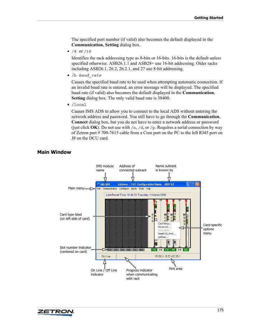
175
Getting Started
The specified port number (if valid) also becomes the default displayed in the Communication, Setting dialog box.
• /8 or /16
Identifies the rack addressing type as 8-bits or 16-bits. 16-bits is the default unless specified otherwise. ASB26.1.1 and ASB28+ use 16-bit addressing. Older racks including ASB26.1, 26.2, 26.2.1, and 27 use 8-bit addressing.
• /b baud_rate
Causes the specified baud rate to be used when attempting automatic connection. If an invalid baud rate is entered, an error message will be displayed. The specified baud rate (if valid) also becomes the default displayed in the Communication, Setting dialog box. The only valid baud rate is 38400.
• /local
Causes IMS ADS to allow you to connect to the local ADS without entering the network address and password. You still have to go through the Communication, Connect dialog box, but you do not have to enter a network address or password (just click OK). Do not use with /n, /d, or /p. Requires a serial connection by way of Zetron part # 709-7615 cable from a Com port on the PC to the left RJ45 port on J8 on the DCU card.
Main Window
IMS modulename
Address ofconnected subrack
Name subrackis known by
Card-specificoptions menu
On Line / Off Lineindicator
Progress indicatorwhen communicatingwith rack
Hint area
Card type label(on left side of card)
Slot number indicator (centered on card)
Main menu
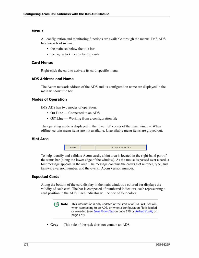
Configuring Acom DS3 Subracks with the IMS ADS Module
176 025-9529P
Menus
All configuration and monitoring functions are available through the menus. IMS ADS has two sets of menus:
• the main set below the title bar
• the right-click menus for the cards
Card Menus
Right-click the card to activate its card-specific menu.
ADS Address and Name
The Acom network address of the ADS and its configuration name are displayed in the main window title bar.
Modes of Operation
IMS ADS has two modes of operation:
• On Line — Connected to an ADS
• Off Line — Working from a configuration file
The operating mode is displayed in the lower left corner of the main window. When offline, certain menu items are not available. Unavailable menu items are grayed out.
Hint Area
To help identify and validate Acom cards, a hint area is located in the right-hand part of the status bar (along the lower edge of the window). As the mouse is passed over a card, a hint message appears in the area. The message contains the card’s slot number, type, and firmware version number, and the overall Acom version number.
Expected Cards
Along the bottom of the card display in the main window, a colored bar displays the validity of each card. The bar is composed of numbered indicators, each representing a card position in the ADS. Each indicator will be one of four colors:
• Gray — This side of the rack does not contain an ADS.
Note This information is only updated at the start of an IMS ADS session, when connecting to an ADS, or when a configuration file is loaded or reloaded (see Load From Disk on page 179 or Reload Config on page 179).
177
Getting Started
• Same color as background — A card is not expected in this slot and none is present.
• Green — A card is expected and present in this slot.
• Yellow — A card is expected and present in this slot, but a fault has been detected in it.
• Red — A card is expected in this slot but is not present, or a card is not expected in this slot but is present.
If a card is expected and not present, the following message will appear in the hint bar:
Expected a “card_type“ card in this slot
If a card is not expected and is present, the following message will appear in the hint bar:
No card was expected in this slot
Card Positions• A DCU card must be installed in slot 1.
• Up to three MCU4 cards can be installed. They can only be installed in slots 2-4.
• One or two MSU3 cards are needed. One must be in slot 6. Another can be in slot 5.
Supported Cards
The IMS ADS application is capable of configuring several types of interface cards. This manual describes their configuration:
• DCU (DS3 Control Unit) — Controls all of the peripheral devices on the DS3, and manages the messaging and signaling data on the ADS backbone. Each side of an ADS can contain only one DCU, and it can only be in slot 1. For configuration information, see DCU Card Options on page 211.
• MCU4 (Main Control Unit) — The primary voice and data switching card in the system. Each side of an ADS can contain 1-3 MCU4s, and they can only be in slots 2-4. Each MCU4 is equipped with dual E1 ports, which can be configured for either of the following uses:
• to connect the E1 loop to an MCU4 card in another ADS, an MCU3 card in an ALS, or a Dual E1 module in an ACU
• to connect to an MCU4 card in an ADS at another site to provide ISB functionality
For configuration information, see MCU4 Card Options on page 219.
• MSU3 (Main Supply Unit) — Provides DC-DC conversion to power a subrack from an external voltage source, converting –48V to +5V and ±12V. Each ADS typically contains just one MSU3, but a second can be added to provide redundant power supplies at the subrack level. There are no configurable options.
Hint Bar
To help identify and validate Acom cards, a hint bar is located in the right-hand part of the status bar (along the lower edge of the window). As the mouse is passed over a card, a
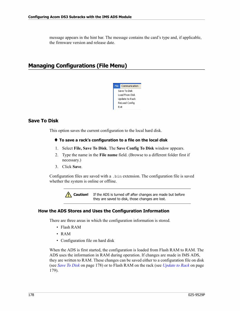
Configuring Acom DS3 Subracks with the IMS ADS Module
178 025-9529P
message appears in the hint bar. The message contains the card’s type and, if applicable, the firmware version and release date.
Managing Configurations (File Menu)
Save To Disk
This option saves the current configuration to the local hard disk.
♦ To save a rack’s configuration to a file on the local disk
1. Select File, Save To Disk. The Save Config To Disk window appears.
2. Type the name in the File name field. (Browse to a different folder first if necessary.)
3. Click Save.
Configuration files are saved with a .bin extension. The configuration file is saved whether the system is online or offline.
How the ADS Stores and Uses the Configuration Information
There are three areas in which the configuration information is stored.
• Flash RAM
• RAM
• Configuration file on hard disk
When the ADS is first started, the configuration is loaded from Flash RAM to RAM. The ADS uses the information in RAM during operation. If changes are made in IMS ADS, they are written to RAM. These changes can be saved either to a configuration file on disk (see Save To Disk on page 178) or to Flash RAM on the rack (see Update to Rack on page 179).
Caution! If the ADS is turned off after changes are made but before they are saved to disk, those changes are lost.
!
179
Managing Configurations (File Menu)
Multiple configurations can be created and saved, but only one configuration can be loaded at a time.
Load From Disk
This option loads a selected configuration from the local hard disk.
♦ To load a configuration file from the local disk
1. Select File, Load From Disk. The Load Config From Disk window appears.
2. Browse to the appropriate folder.
3. Select the desired .bin file.
4. Click Open.
Update to Rack
This option uploads the currently loaded configuration to Flash RAM on the rack.
♦ To update the rack
1. Load the appropriate configuration.
2. Select File, Update to Rack. If the system is offline, you will be prompted to connect to the ADS.
3. Type in the Network Address of the ADS.
4. Click OK.
Reload Config
Selecting this option reloads the configuration from the ADS or from the disk file loaded, whichever is applicable. This option is not available in Off Line mode.
Exit
Selecting this option closes the IMS ADS application.
Note The configuration file is opened whether the system is online or offline. When a configuration file is loaded, the ADS is disconnected from the Maintenance Terminal. To reestablish a connection, you must connect again, using the Communication menu.
Caution! You will not be prompted for confirmation to exit. You will not be prompted to save any changes to the loaded configuration; if you want to make sure your changes are saved, use the Save To Disk option and/or the Update to Rack option first.
!
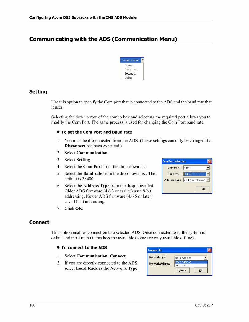
Configuring Acom DS3 Subracks with the IMS ADS Module
180 025-9529P
Communicating with the ADS (Communication Menu)
Setting
Use this option to specify the Com port that is connected to the ADS and the baud rate that it uses.
Selecting the down arrow of the combo box and selecting the required port allows you to modify the Com Port. The same process is used for changing the Com Port baud rate.
♦ To set the Com Port and Baud rate
1. You must be disconnected from the ADS. (These settings can only be changed if a Disconnect has been executed.)
2. Select Communication.
3. Select Setting.
4. Select the Com Port from the drop-down list.
5. Select the Baud rate from the drop-down list. The default is 38400.
6. Select the Address Type from the drop-down list. Older ADS firmware (4.6.3 or earlier) uses 8-bit addressing. Newer ADS firmware (4.6.5 or later) uses 16-bit addressing.
7. Click OK.
Connect
This option enables connection to a selected ADS. Once connected to it, the system is online and most menu items become available (some are only available offline).
♦ To connect to the ADS
1. Select Communication, Connect.
2. If you are directly connected to the ADS, select Local Rack as the Network Type.
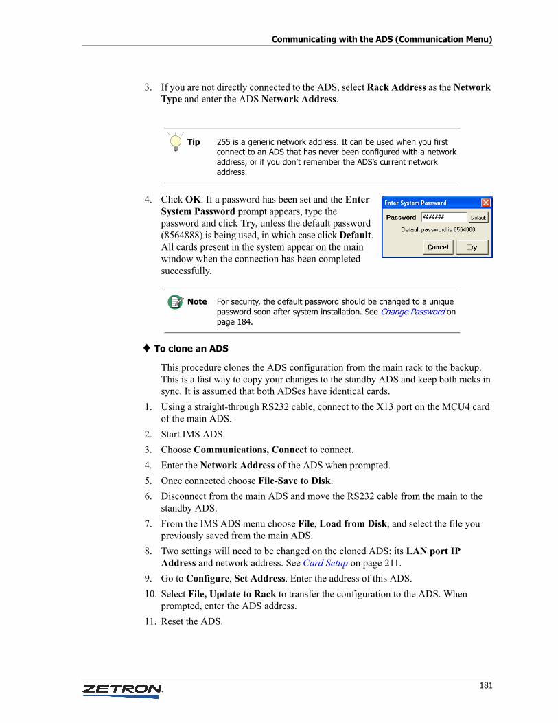
181
Communicating with the ADS (Communication Menu)
3. If you are not directly connected to the ADS, select Rack Address as the Network Type and enter the ADS Network Address.
4. Click OK. If a password has been set and the Enter System Password prompt appears, type the password and click Try, unless the default password (8564888) is being used, in which case click Default. All cards present in the system appear on the main window when the connection has been completed successfully.
♦ To clone an ADS
This procedure clones the ADS configuration from the main rack to the backup. This is a fast way to copy your changes to the standby ADS and keep both racks in sync. It is assumed that both ADSes have identical cards.
1. Using a straight-through RS232 cable, connect to the X13 port on the MCU4 card of the main ADS.
2. Start IMS ADS.
3. Choose Communications, Connect to connect.
4. Enter the Network Address of the ADS when prompted.
5. Once connected choose File-Save to Disk.
6. Disconnect from the main ADS and move the RS232 cable from the main to the standby ADS.
7. From the IMS ADS menu choose File, Load from Disk, and select the file you previously saved from the main ADS.
8. Two settings will need to be changed on the cloned ADS: its LAN port IP Address and network address. See Card Setup on page 211.
9. Go to Configure, Set Address. Enter the address of this ADS.
10. Select File, Update to Rack to transfer the configuration to the ADS. When prompted, enter the ADS address.
11. Reset the ADS.
Tip 255 is a generic network address. It can be used when you first connect to an ADS that has never been configured with a network address, or if you don’t remember the ADS’s current network address.
Note For security, the default password should be changed to a unique password soon after system installation. See Change Password on page 184.
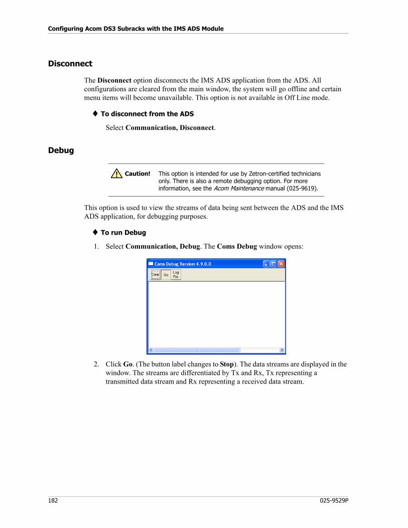
Configuring Acom DS3 Subracks with the IMS ADS Module
182 025-9529P
Disconnect
The Disconnect option disconnects the IMS ADS application from the ADS. All configurations are cleared from the main window, the system will go offline and certain menu items will become unavailable. This option is not available in Off Line mode.
♦ To disconnect from the ADS
Select Communication, Disconnect.
Debug
This option is used to view the streams of data being sent between the ADS and the IMS ADS application, for debugging purposes.
♦ To run Debug
1. Select Communication, Debug. The Coms Debug window opens:
2. Click Go. (The button label changes to Stop). The data streams are displayed in the window. The streams are differentiated by Tx and Rx, Tx representing a transmitted data stream and Rx representing a received data stream.
Caution! This option is intended for use by Zetron-certified technicians only. There is also a remote debugging option. For more information, see the Acom Maintenance manual (025-9619).
!
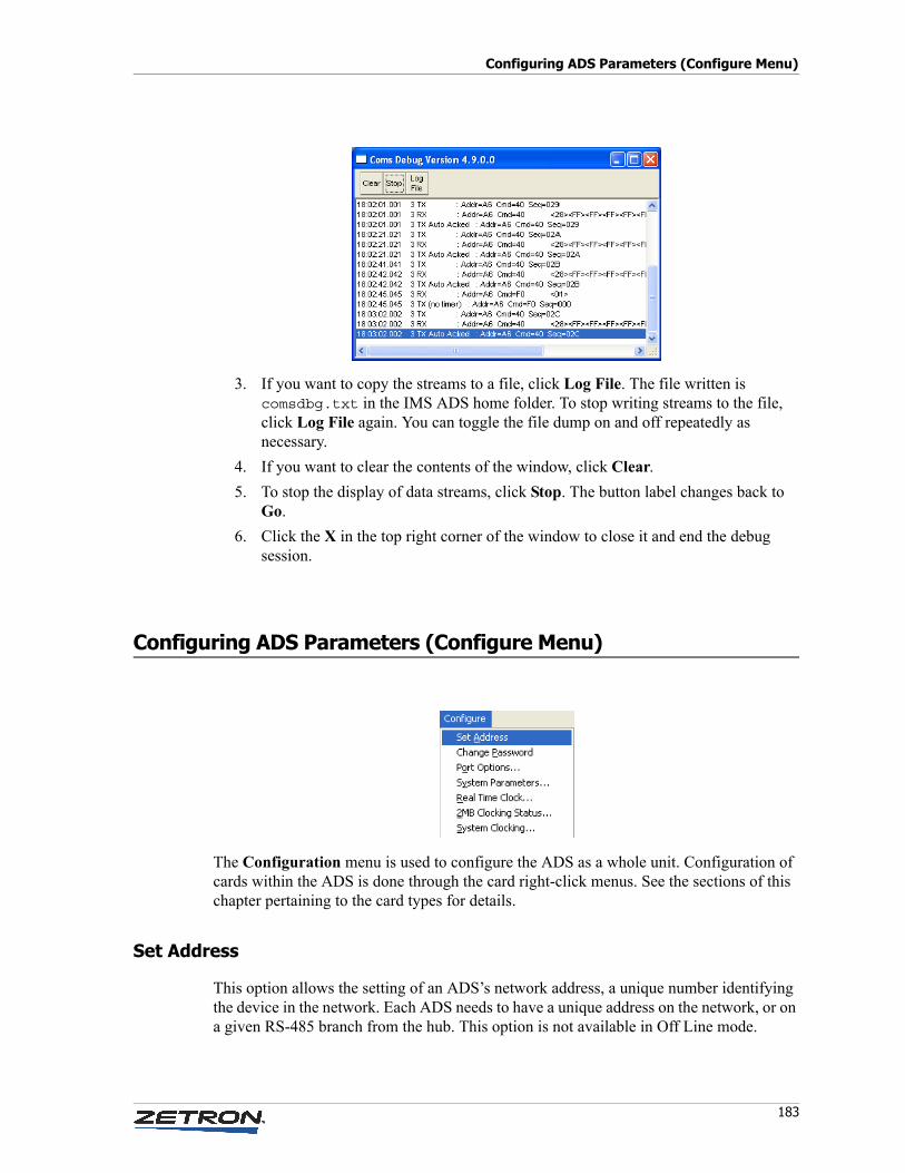
183
Configuring ADS Parameters (Configure Menu)
3. If you want to copy the streams to a file, click Log File. The file written is comsdbg.txt in the IMS ADS home folder. To stop writing streams to the file, click Log File again. You can toggle the file dump on and off repeatedly as necessary.
4. If you want to clear the contents of the window, click Clear.
5. To stop the display of data streams, click Stop. The button label changes back to Go.
6. Click the X in the top right corner of the window to close it and end the debug session.
Configuring ADS Parameters (Configure Menu)
The Configuration menu is used to configure the ADS as a whole unit. Configuration of cards within the ADS is done through the card right-click menus. See the sections of this chapter pertaining to the card types for details.
Set Address
This option allows the setting of an ADS’s network address, a unique number identifying the device in the network. Each ADS needs to have a unique address on the network, or on a given RS-485 branch from the hub. This option is not available in Off Line mode.
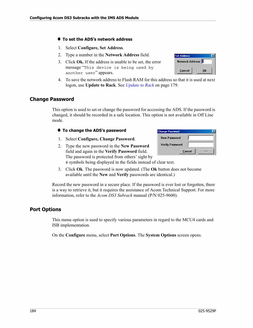
Configuring Acom DS3 Subracks with the IMS ADS Module
184 025-9529P
♦ To set the ADS’s network address
1. Select Configure, Set Address.
2. Type a number in the Network Address field.
3. Click Ok. If the address is unable to be set, the error message “This device is being used by another user” appears.
4. To save the network address to Flash RAM for this address so that it is used at next logon, use Update to Rack. See Update to Rack on page 179.
Change Password
This option is used to set or change the password for accessing the ADS. If the password is changed, it should be recorded in a safe location. This option is not available in Off Line mode.
♦ To change the ADS’s password
1. Select Configure, Change Password.
2. Type the new password in the New Password field and again in the Verify Password field. The password is protected from others’ sight by # symbols being displayed in the fields instead of clear text.
3. Click Ok. The password is now updated. (The Ok button does not become available until the New and Verify passwords are identical.)
Record the new password in a secure place. If the password is ever lost or forgotten, there is a way to retrieve it, but it requires the assistance of Acom Technical Support. For more information, refer to the Acom DS3 Subrack manual (P/N 025-9600).
Port Options
This menu option is used to specify various parameters in regard to the MCU4 cards and ISB implementation.
On the Configure menu, select Port Options. The System Options screen opens.
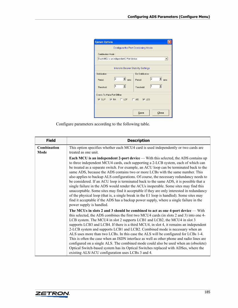
185
Configuring ADS Parameters (Configure Menu)
Configure parameters according to the following table.
Field Description
CombinationMode
This option specifies whether each MCU4 card is used independently or two cards are treated as one unit.
Each MCU is an independent 2-port device — With this selected, the ADS contains up to three independent MCU4 cards, each supporting a 2-LCB system, each of which can be treated as a separate switch. For example, an ACU loop can be terminated back to the same ADS, because the ADS contains two or more LCBs with the same number. This also applies to backup ALS configurations. Of course, the necessary redundancy needs to be considered. If an ACU loop is terminated back to the same ADS, it is possible that a single failure in the ADS would render the ACUs inoperable. Some sites may find this unacceptable. Some sites may find it acceptable if they are only interested in redundancy of the physical loop (that is, a single break in the E1 loop is handled). Some sites may find it acceptable if the ADS has a backup power supply, where a single failure in the power supply is handled.
The MCUs in slots 2 and 3 should be combined to act as one 4-port device — With this selected, the ADS combines the first two MCU4 cards (in slots 2 and 3) into one 4-LCB system. The MCU4 in slot 2 supports LCB1 and LCB2, the MCU4 in slot 3 supports LCB3 and LCB4. If there is a third MCU4, in slot 4, it remains an independent 2-LCB system and supports LCB1 and LCB2. Combined mode is necessary when an ALS uses more than two LCBs. In this case the ALS will be configured for LCBs 1-4. This is often the case when an ISDN interface as well as other phone and radio lines are configured on a single ALS. The combined mode could also be used when an (obsolete) Optical Switch-based system has its Optical Switches replaced with ADSes, where the existing ALS/ACU configuration uses LCBs 3 and 4.
Configuring Acom DS3 Subracks with the IMS ADS Module
186 025-9529P
System Parameters
Use this option to configure the following operational parameters for this ADS.
• whether this ADS will be the source of System Parameters for all other ADSes at the site
• the number of the site within the Acom system
• timeout periods for autocalls
• when autocalls should be removed from queues
• whether beeps will be transmitted during conference calls
• whether this ADS holds the configuration that should be used by all ADSes at the site when pseudo-duplexing group and conference calls
• whether multiple holds will be allowed
• whether to send alarms across ISBs
• the GMT offset
• whether Daylight Saving Time should be observed and, if so, the DST start and end date and time
• which, if any, digital inputs or outputs should be replicated across ISBs
StabilizationandDestabilization
These parameters enable monitoring of performance markers on ISB ports. The purpose is to provide longer-term stability data on the ports, to minimize the frequency of enabling/disabling ISB ports, and ultimately the frequency of ISB changeovers (either main/standby or main/backup). If set, these parameters will apply to all ISB ports on this ADS.
Each bearer port is monitored using a sliding window of time. If the number of events (of types selected under Events To Make Port Offline) that occur during any contiguous number of minutes specified by Destabilization Period exceeds the number specified by Destabilization Threshold, the port is temporarily disabled. This will cause a changeover to a standby bearer group if the port is configured for redundancy (see Port Mode on page 219). The port will remain unavailable until the number of events occurring during any contiguous number of minutes specified by Stabilization Period falls below the number specified by Stabilization Threshold. The port will then be enabled again, and a change-over of the bearer group back to the Main group may occur. Range for both Stabilization Period and Destabilization Period is 0-30 minutes. Default for Stabilization Period is 0, which means that a port that has destabilized will never automatically stabilize; the port must be reset manually (see ISB Status on page 207). Default for destabilization Period is 0, which means the performance stabilizing system is disabled, that is ports never destabilize.
Events To MakePort Offline
Specify the types of event that will cause a change-over to a standby bearer group: SLIP (slip is occurring on the receive line of the link), RA (receiving remote alarms from the remote end), LOF (loss of frame), AIS (alarm indication signal is being sent to the remote end), and/or LOS (loss of synchronization on the link). Only the event types selected here will be monitored for link integrity.
Field Description
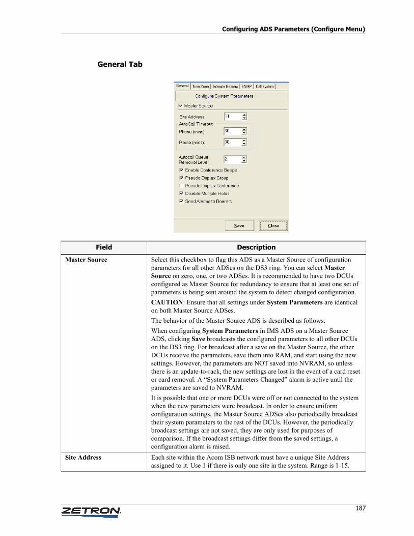
187
Configuring ADS Parameters (Configure Menu)
General Tab
Field Description
Master Source Select this checkbox to flag this ADS as a Master Source of configuration parameters for all other ADSes on the DS3 ring. You can select Master Source on zero, one, or two ADSes. It is recommended to have two DCUs configured as Master Source for redundancy to ensure that at least one set of parameters is being sent around the system to detect changed configuration.
CAUTION: Ensure that all settings under System Parameters are identical on both Master Source ADSes.
The behavior of the Master Source ADS is described as follows.
When configuring System Parameters in IMS ADS on a Master Source ADS, clicking Save broadcasts the configured parameters to all other DCUs on the DS3 ring. For broadcast after a save on the Master Source, the other DCUs receive the parameters, save them into RAM, and start using the new settings. However, the parameters are NOT saved into NVRAM, so unless there is an update-to-rack, the new settings are lost in the event of a card reset or card removal. A “System Parameters Changed” alarm is active until the parameters are saved to NVRAM.
It is possible that one or more DCUs were off or not connected to the system when the new parameters were broadcast. In order to ensure uniform configuration settings, the Master Source ADSes also periodically broadcast their system parameters to the rest of the DCUs. However, the periodically broadcast settings are not saved, they are only used for purposes of comparison. If the broadcast settings differ from the saved settings, a configuration alarm is raised.
Site Address Each site within the Acom ISB network must have a unique Site Address assigned to it. Use 1 if there is only one site in the system. Range is 1-15.
Configuring Acom DS3 Subracks with the IMS ADS Module
188 025-9529P
Autocall Timeouts Autocalls will be automatically disconnected after the specified period of time. Works whether the Autocall was established by way of Lookup Data in IMS ALS (see page 48) or by way of the Call Transfer function on the console (see the Acom Console Operation manual). The timeout periods for Radio lines and Phone lines can be set to different values. Range is 0-250 minutes. Default is 30 minutes.
Auto Call Queue Removal Level
0 = When a call is answered, it is not automatically removed from any console’s queue, unless RemoveEntryOnSelection = True is set in the console’s AcomConsole.ini file.1 = When a channel is keyed up, all calls from that channel are removed from all consoles’ Enhanced Radio Queues.2 = When a channel is keyed up, and a Selcal is transmitted and addressed to a specific mobile, calls from that mobile on that channel are removed from all consoles’ Enhanced Radio Queues. For more information on the Enhanced Radio Queue, see [Queue Box] on page 361.
Enable Conference Beeps The system conference tone is heard each time an additional line is grouped or conferenced to an existing call. If the Tx and Rx on group option is set in the line definition, the conference beep will also be heard if another operator joins the call.
Pseudo Duplex GroupandPseudo Duplex Conference
If selected, specifies that this is the ADS that holds the configuration for pseudo duplex group/conference that should be used by all Acom DS3 Switches (ADSes). If an ADS does not have a connected ALS, it will need a way to determine how to treat the connected consoles. By selecting this checkbox on one ADS, the pseudo duplex settings will be used by all ADSes. (If all ADSes have a connected ALS and are configured identically, this may not be necessary.) This provides the facility for the ADS to get the behavior of pseudo duplex group/conference from one of the ADSes, the Master Source.
See also Pseudo Duplex - Group and Pseudo Duplex - Conf on page 53.
Disable Multiple Holds If unselected, the default hold operation will result, in which multiple consoles can place a call on hold. If selected, a line will be taken off hold when another console selects it, and consoles will be prevented from placing a call on hold if another console has the line selected.
Send Alarms To Bearers Valid only where ISBs are implemented. Enables alarms to be sent over ISBs, this allows consoles to view alarms from remote sites. See also Implementing Intersite Bearers on page 220.
Field Description
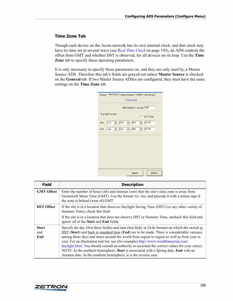
189
Configuring ADS Parameters (Configure Menu)
Time Zone Tab
Though each device on the Acom network has its own internal clock, and that clock may have its time set in several ways (see Real Time Clock on page 192), an ADS controls the offset from GMT and whether DST is observed, for all devices on its loop. Use the Time Zone tab to specify these operating parameters.
It is only necessary to specify these parameters on, and they are only used by, a Master Source ADS. Therefore this tab’s fields are grayed out unless Master Source is checked on the General tab. If two Master Source ADSes are configured, they must have the same settings on the Time Zone tab.
Field Description
GMT Offset Enter the number of hours (hh) and minutes (mm) that the site’s time zone is away from Greenwich Mean Time (GMT). Use the format hh:mm, and precede it with a minus sign if the zone is behind (west of) GMT.
DST Offset If the site is in a location that observes Daylight Saving Time (DST) (or any other variety of Summer Time), check this field.
If the site is in a location that does not observe DST or Summer Time, uncheck this field and ignore all of the Start and End fields.
StartandEnd
Specify the day (first three fields) and time (last field, in 24-hr format) on which the switch to DST (Start) and back to standard time (End) are to be made. There is considerable variance among these days and times around the world from region to region as well as from year to year. For an illustration and list, see (for example) http://www.worldtimezone.com/daylight.html. You should consult an authority to ascertain the correct values for your site(s). NOTE: In the northern hemisphere, Start is associated with a Spring date, End with an Autumn date. In the southern hemisphere, it is the reverse case.
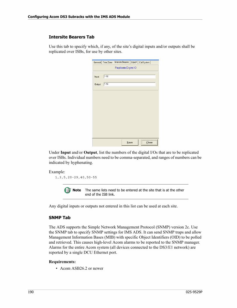
Configuring Acom DS3 Subracks with the IMS ADS Module
190 025-9529P
Intersite Bearers Tab
Use this tab to specify which, if any, of the site’s digital inputs and/or outputs shall be replicated over ISBs, for use by other sites.
Under Input and/or Output, list the numbers of the digital I/Os that are to be replicated over ISBs. Individual numbers need to be comma-separated, and ranges of numbers can be indicated by hyphenating.
Example:1,3,5,20-29,40,50-55
Any digital inputs or outputs not entered in this list can be used at each site.
SNMP Tab
The ADS supports the Simple Network Management Protocol (SNMP) version 2c. Use the SNMP tab to specify SNMP settings for IMS ADS. It can send SNMP traps and allow Management Information Bases (MIB) with specific Object Identifiers (OID) to be polled and retrieved. This causes high-level Acom alarms to be reported to the SNMP manager. Alarms for the entire Acom system (all devices connected to the DS3/E1 network) are reported by a single DCU Ethernet port.
Requirements:
• Acom ASB26.2 or newer
Note The same lists need to be entered at the site that is at the other end of the ISB link.
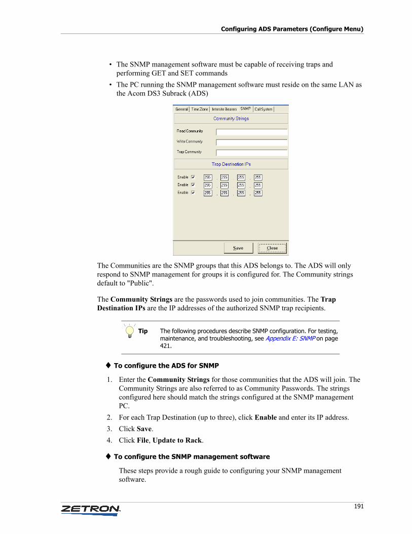
191
Configuring ADS Parameters (Configure Menu)
• The SNMP management software must be capable of receiving traps and performing GET and SET commands
• The PC running the SNMP management software must reside on the same LAN as the Acom DS3 Subrack (ADS)
The Communities are the SNMP groups that this ADS belongs to. The ADS will only respond to SNMP management for groups it is configured for. The Community strings default to "Public".
The Community Strings are the passwords used to join communities. The Trap Destination IPs are the IP addresses of the authorized SNMP trap recipients.
♦ To configure the ADS for SNMP
1. Enter the Community Strings for those communities that the ADS will join. The Community Strings are also referred to as Community Passwords. The strings configured here should match the strings configured at the SNMP management PC.
2. For each Trap Destination (up to three), click Enable and enter its IP address.
3. Click Save.
4. Click File, Update to Rack.
♦ To configure the SNMP management software
These steps provide a rough guide to configuring your SNMP management software.
Tip The following procedures describe SNMP configuration. For testing, maintenance, and troubleshooting, see Appendix E: SNMP on page 421.
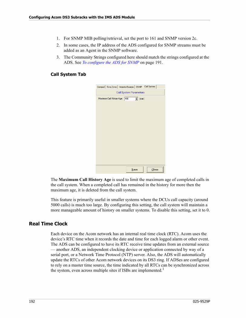
Configuring Acom DS3 Subracks with the IMS ADS Module
192 025-9529P
1. For SNMP MIB polling/retrieval, set the port to 161 and SNMP version 2c.
2. In some cases, the IP address of the ADS configured for SNMP streams must be added as an Agent in the SNMP software.
3. The Community Strings configured here should match the strings configured at the ADS. See To configure the ADS for SNMP on page 191.
Call System Tab
The Maximum Call History Age is used to limit the maximum age of completed calls in the call system. When a completed call has remained in the history for more then the maximum age, it is deleted from the call system.
This feature is primarily useful in smaller systems where the DCUs call capacity (around 5000 calls) is much too large. By configuring this setting, the call system will maintain a more manageable amount of history on smaller systems. To disable this setting, set it to 0.
Real Time Clock
Each device on the Acom network has an internal real time clock (RTC). Acom uses the device’s RTC time when it records the date and time for each logged alarm or other event. The ADS can be configured to have its RTC receive time updates from an external source — another ADS, an independent clocking device or application connected by way of a serial port, or a Network Time Protocol (NTP) server. Also, the ADS will automatically update the RTCs of other Acom network devices on its DS3 ring. If ADSes are configured to rely on a master time source, the time indicated by all RTCs can be synchronized across the system, even across multiple sites if ISBs are implemented.1
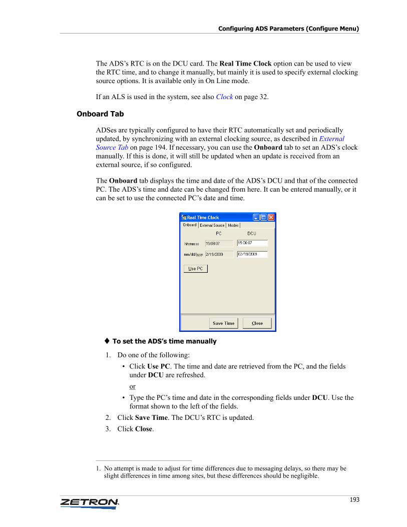
193
Configuring ADS Parameters (Configure Menu)
The ADS’s RTC is on the DCU card. The Real Time Clock option can be used to view the RTC time, and to change it manually, but mainly it is used to specify external clocking source options. It is available only in On Line mode.
If an ALS is used in the system, see also Clock on page 32.
Onboard Tab
ADSes are typically configured to have their RTC automatically set and periodically updated, by synchronizing with an external clocking source, as described in External Source Tab on page 194. If necessary, you can use the Onboard tab to set an ADS’s clock manually. If this is done, it will still be updated when an update is received from an external source, if so configured.
The Onboard tab displays the time and date of the ADS’s DCU and that of the connected PC. The ADS’s time and date can be changed from here. It can be entered manually, or it can be set to use the connected PC’s date and time.
♦ To set the ADS’s time manually
1. Do one of the following:
• Click Use PC. The time and date are retrieved from the PC, and the fields under DCU are refreshed.
or
• Type the PC’s time and date in the corresponding fields under DCU. Use the format shown to the left of the fields.
2. Click Save Time. The DCU’s RTC is updated.
3. Click Close.
1. No attempt is made to adjust for time differences due to messaging delays, so there may be slight differences in time among sites, but these differences should be negligible.
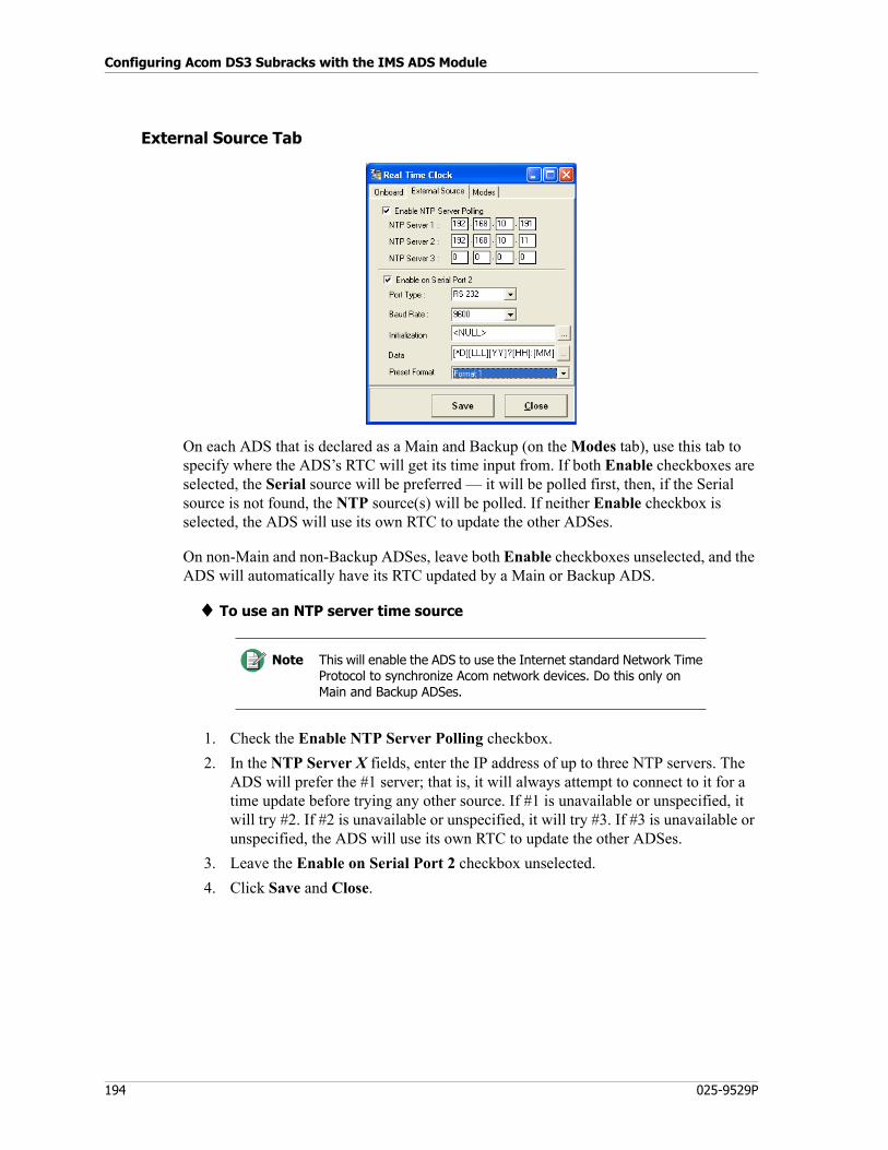
Configuring Acom DS3 Subracks with the IMS ADS Module
194 025-9529P
External Source Tab
On each ADS that is declared as a Main and Backup (on the Modes tab), use this tab to specify where the ADS’s RTC will get its time input from. If both Enable checkboxes are selected, the Serial source will be preferred — it will be polled first, then, if the Serial source is not found, the NTP source(s) will be polled. If neither Enable checkbox is selected, the ADS will use its own RTC to update the other ADSes.
On non-Main and non-Backup ADSes, leave both Enable checkboxes unselected, and the ADS will automatically have its RTC updated by a Main or Backup ADS.
♦ To use an NTP server time source
1. Check the Enable NTP Server Polling checkbox.
2. In the NTP Server X fields, enter the IP address of up to three NTP servers. The ADS will prefer the #1 server; that is, it will always attempt to connect to it for a time update before trying any other source. If #1 is unavailable or unspecified, it will try #2. If #2 is unavailable or unspecified, it will try #3. If #3 is unavailable or unspecified, the ADS will use its own RTC to update the other ADSes.
3. Leave the Enable on Serial Port 2 checkbox unselected.
4. Click Save and Close.
Note This will enable the ADS to use the Internet standard Network Time Protocol to synchronize Acom network devices. Do this only on Main and Backup ADSes.
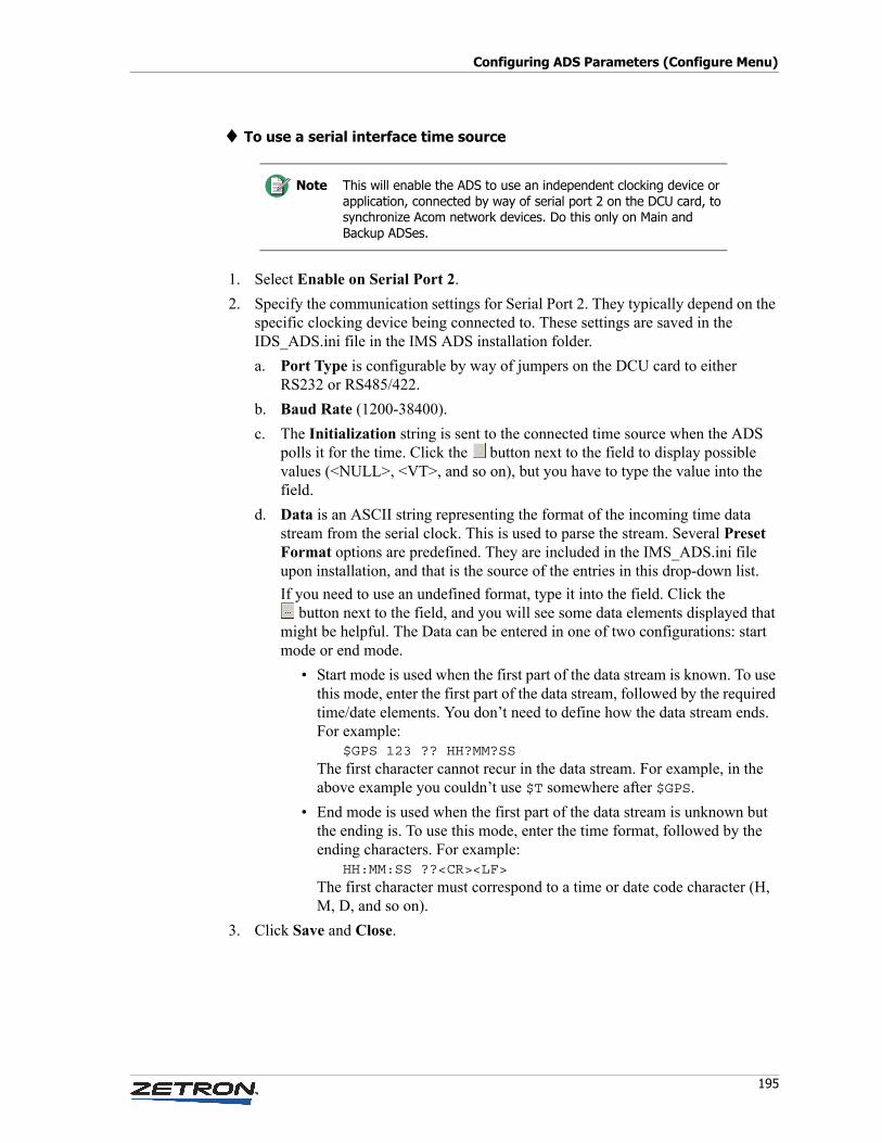
195
Configuring ADS Parameters (Configure Menu)
♦ To use a serial interface time source
1. Select Enable on Serial Port 2.
2. Specify the communication settings for Serial Port 2. They typically depend on the specific clocking device being connected to. These settings are saved in the IDS_ADS.ini file in the IMS ADS installation folder.
a. Port Type is configurable by way of jumpers on the DCU card to either RS232 or RS485/422.
b. Baud Rate (1200-38400).
c. The Initialization string is sent to the connected time source when the ADS polls it for the time. Click the button next to the field to display possible values (<NULL>, <VT>, and so on), but you have to type the value into the field.
d. Data is an ASCII string representing the format of the incoming time data stream from the serial clock. This is used to parse the stream. Several Preset Format options are predefined. They are included in the IMS_ADS.ini file upon installation, and that is the source of the entries in this drop-down list.
If you need to use an undefined format, type it into the field. Click the button next to the field, and you will see some data elements displayed that
might be helpful. The Data can be entered in one of two configurations: start mode or end mode.
• Start mode is used when the first part of the data stream is known. To use this mode, enter the first part of the data stream, followed by the required time/date elements. You don’t need to define how the data stream ends. For example:
$GPS 123 ?? HH?MM?SSThe first character cannot recur in the data stream. For example, in the above example you couldn’t use $T somewhere after $GPS.
• End mode is used when the first part of the data stream is unknown but the ending is. To use this mode, enter the time format, followed by the ending characters. For example:
HH:MM:SS ??<CR><LF>The first character must correspond to a time or date code character (H, M, D, and so on).
3. Click Save and Close.
Note This will enable the ADS to use an independent clocking device or application, connected by way of serial port 2 on the DCU card, to synchronize Acom network devices. Do this only on Main and Backup ADSes.
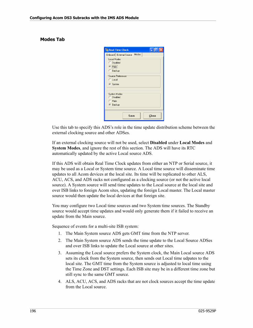
Configuring Acom DS3 Subracks with the IMS ADS Module
196 025-9529P
Modes Tab
Use this tab to specify this ADS’s role in the time update distribution scheme between the external clocking source and other ADSes.
If an external clocking source will not be used, select Disabled under Local Modes and System Modes, and ignore the rest of this section. The ADS will have its RTC automatically updated by the active Local source ADS.
If this ADS will obtain Real Time Clock updates from either an NTP or Serial source, it may be used as a Local or System time source. A Local time source will disseminate time updates to all Acom devices at the local site. Its time will be replicated to other ALS, ACU, ACS, and ADS racks not configured as a clocking source (or not the active local source). A System source will send time updates to the Local source at the local site and over ISB links to foreign Acom sites, updating the foreign Local master. The Local master source would then update the local devices at that foreign site.
You may configure two Local time sources and two System time sources. The Standby source would accept time updates and would only generate them if it failed to receive an update from the Main source.
Sequence of events for a multi-site ISB system:
1. The Main System source ADS gets GMT time from the NTP server.
2. The Main System source ADS sends the time update to the Local Source ADSes and over ISB links to update the Local source at other sites.
3. Assuming the Local source prefers the System clock, the Main Local source ADS sets its clock from the System source, then sends out Local time udpates to the local site. The GMT time from the System source is adjusted to local time using the Time Zone and DST settings. Each ISB site may be in a different time zone but still sync to the same GMT source.
4. ALS, ACU, ACS, and ADS racks that are not clock sources accept the time update from the Local source.
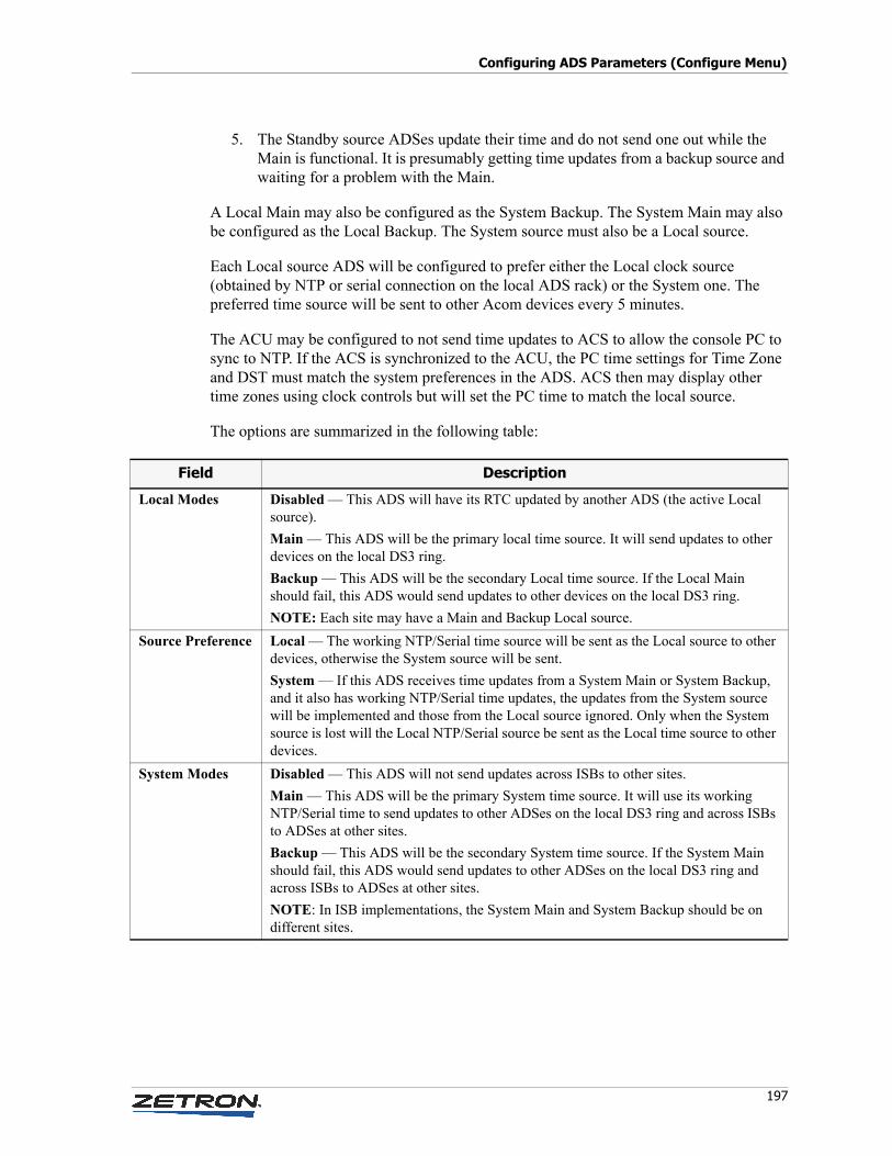
197
Configuring ADS Parameters (Configure Menu)
5. The Standby source ADSes update their time and do not send one out while the Main is functional. It is presumably getting time updates from a backup source and waiting for a problem with the Main.
A Local Main may also be configured as the System Backup. The System Main may also be configured as the Local Backup. The System source must also be a Local source.
Each Local source ADS will be configured to prefer either the Local clock source (obtained by NTP or serial connection on the local ADS rack) or the System one. The preferred time source will be sent to other Acom devices every 5 minutes.
The ACU may be configured to not send time updates to ACS to allow the console PC to sync to NTP. If the ACS is synchronized to the ACU, the PC time settings for Time Zone and DST must match the system preferences in the ADS. ACS then may display other time zones using clock controls but will set the PC time to match the local source.
The options are summarized in the following table:
Field Description
Local Modes Disabled — This ADS will have its RTC updated by another ADS (the active Local source).
Main — This ADS will be the primary local time source. It will send updates to other devices on the local DS3 ring.
Backup — This ADS will be the secondary Local time source. If the Local Main should fail, this ADS would send updates to other devices on the local DS3 ring.
NOTE: Each site may have a Main and Backup Local source.
Source Preference Local — The working NTP/Serial time source will be sent as the Local source to other devices, otherwise the System source will be sent.
System — If this ADS receives time updates from a System Main or System Backup, and it also has working NTP/Serial time updates, the updates from the System source will be implemented and those from the Local source ignored. Only when the System source is lost will the Local NTP/Serial source be sent as the Local time source to other devices.
System Modes Disabled — This ADS will not send updates across ISBs to other sites.
Main — This ADS will be the primary System time source. It will use its working NTP/Serial time to send updates to other ADSes on the local DS3 ring and across ISBs to ADSes at other sites.
Backup — This ADS will be the secondary System time source. If the System Main should fail, this ADS would send updates to other ADSes on the local DS3 ring and across ISBs to ADSes at other sites.
NOTE: In ISB implementations, the System Main and System Backup should be on different sites.
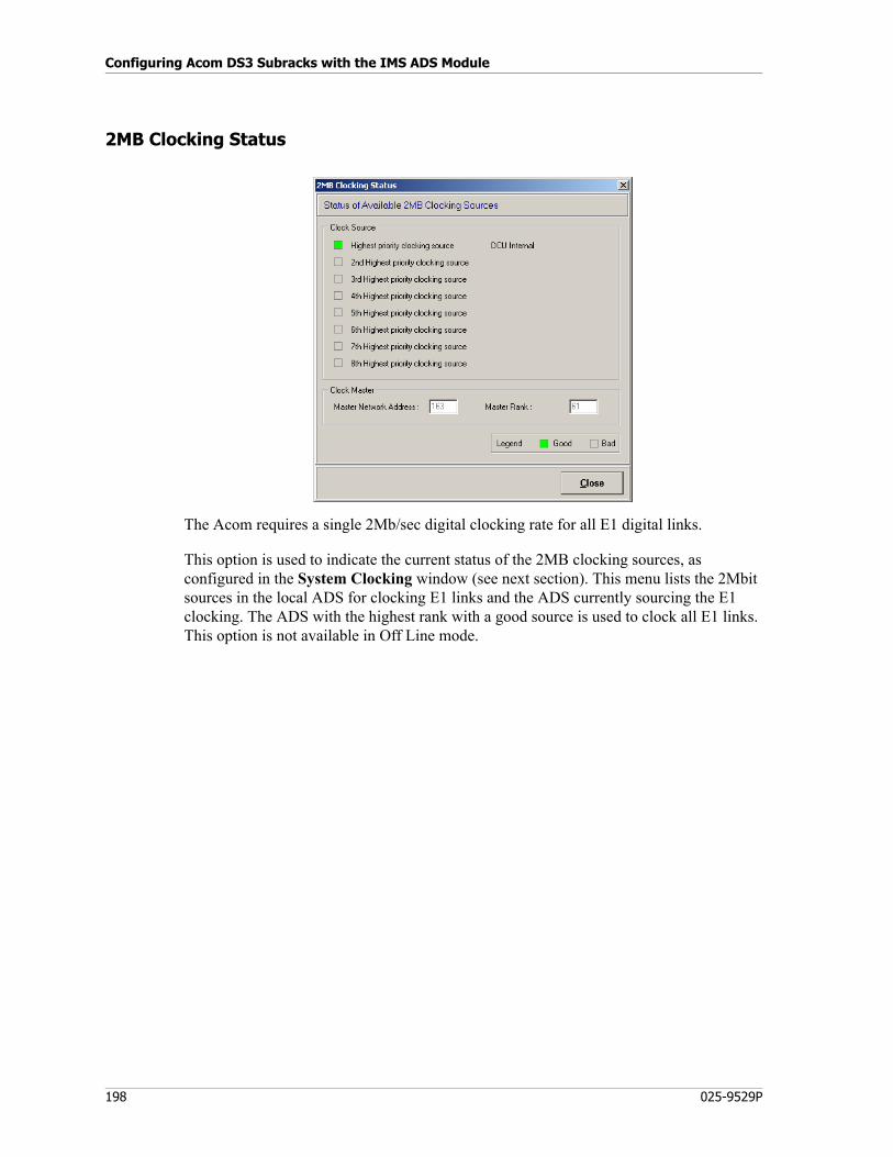
Configuring Acom DS3 Subracks with the IMS ADS Module
198 025-9529P
2MB Clocking Status
The Acom requires a single 2Mb/sec digital clocking rate for all E1 digital links.
This option is used to indicate the current status of the 2MB clocking sources, as configured in the System Clocking window (see next section). This menu lists the 2Mbit sources in the local ADS for clocking E1 links and the ADS currently sourcing the E1 clocking. The ADS with the highest rank with a good source is used to clock all E1 links. This option is not available in Off Line mode.
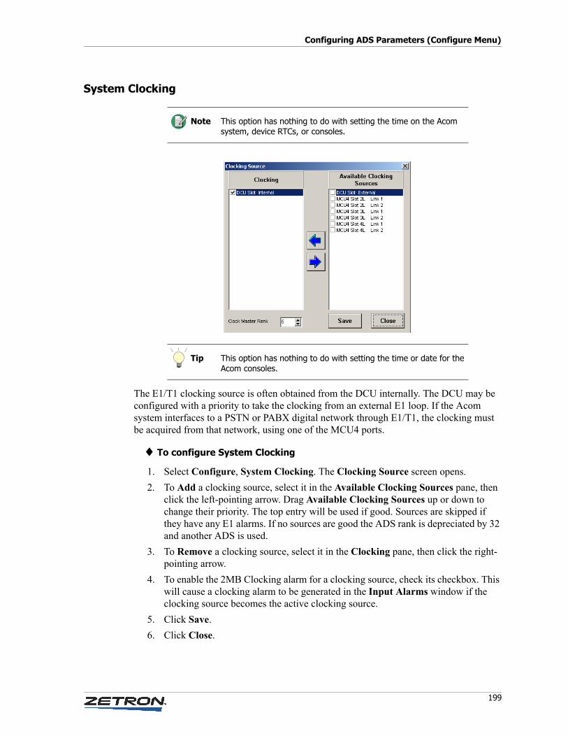
199
Configuring ADS Parameters (Configure Menu)
System Clocking
The E1/T1 clocking source is often obtained from the DCU internally. The DCU may be configured with a priority to take the clocking from an external E1 loop. If the Acom system interfaces to a PSTN or PABX digital network through E1/T1, the clocking must be acquired from that network, using one of the MCU4 ports.
♦ To configure System Clocking
1. Select Configure, System Clocking. The Clocking Source screen opens.
2. To Add a clocking source, select it in the Available Clocking Sources pane, then click the left-pointing arrow. Drag Available Clocking Sources up or down to change their priority. The top entry will be used if good. Sources are skipped if they have any E1 alarms. If no sources are good the ADS rank is depreciated by 32 and another ADS is used.
3. To Remove a clocking source, select it in the Clocking pane, then click the right-pointing arrow.
4. To enable the 2MB Clocking alarm for a clocking source, check its checkbox. This will cause a clocking alarm to be generated in the Input Alarms window if the clocking source becomes the active clocking source.
5. Click Save.
6. Click Close.
Note This option has nothing to do with setting the time on the Acom system, device RTCs, or consoles.
Tip This option has nothing to do with setting the time or date for the Acom consoles.
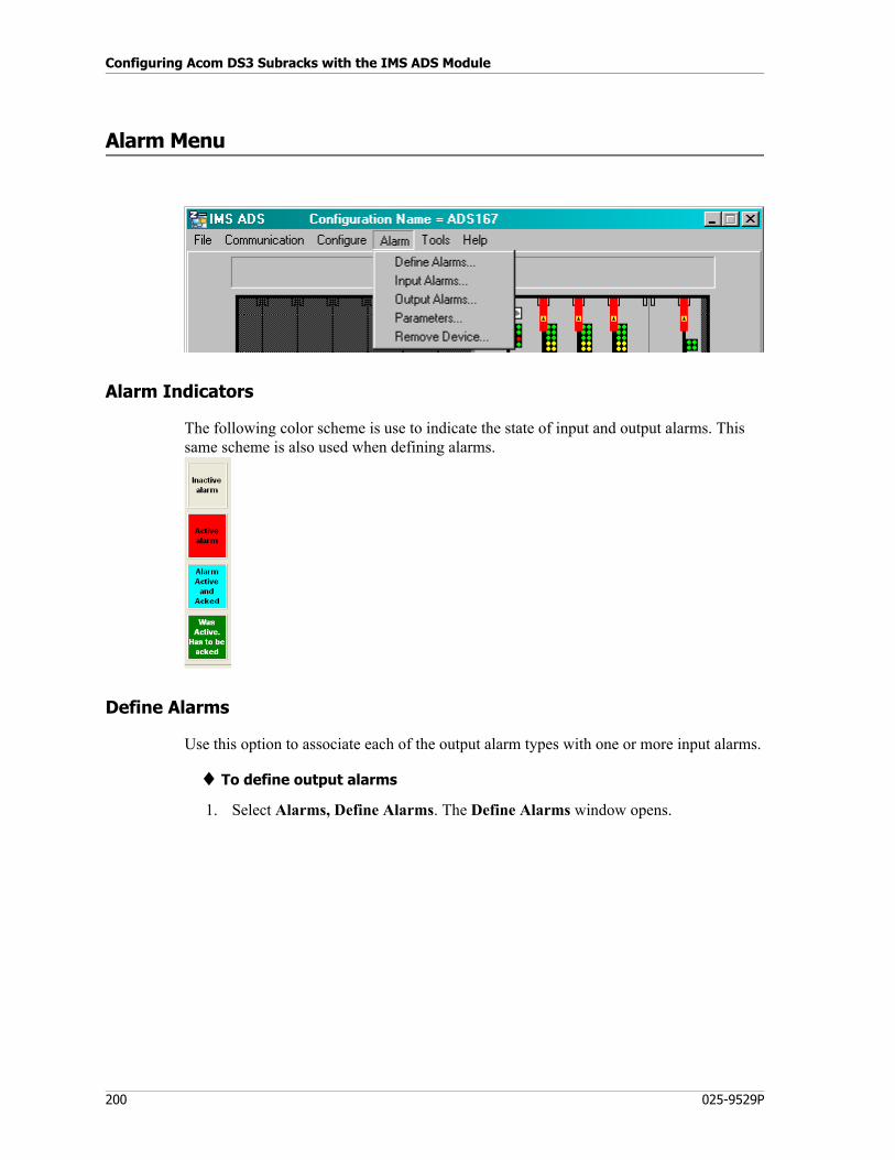
Configuring Acom DS3 Subracks with the IMS ADS Module
200 025-9529P
Alarm Menu
Alarm Indicators
The following color scheme is use to indicate the state of input and output alarms. This same scheme is also used when defining alarms.
Define Alarms
Use this option to associate each of the output alarm types with one or more input alarms.
♦ To define output alarms
1. Select Alarms, Define Alarms. The Define Alarms window opens.
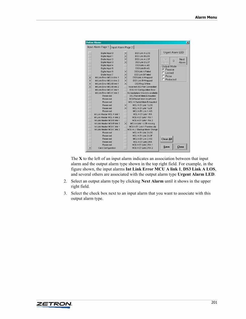
201
Alarm Menu
The X to the left of an input alarm indicates an association between that input alarm and the output alarm type shown in the top right field. For example, in the figure shown, the input alarms Int Link Error MCU A link 1, DS3 Link A LOS, and several others are associated with the output alarm type Urgent Alarm LED.
2. Select an output alarm type by clicking Next Alarm until it shows in the upper right field.
3. Select the check box next to an input alarm that you want to associate with this output alarm type.
Configuring Acom DS3 Subracks with the IMS ADS Module
202 025-9529P
4. Select the Output Mode for this alarm, according to the following table:
5. Repeat steps 3-4 for all of the other input alarms that you want to associate with this output alarm type. Note that there are two tabs of input alarms.
6. Return to step 2 and choose the next output alarm type. Repeat this process until all output alarm types have the appropriate input alarms and output mode associated with them.
7. Click Save and Close.
Input Alarms
Use this option to view and acknowledge input alarms. This option is not available when the system is offline.
Alarms shown as N/A or Reserved are not available in the system.
Mode Description
Passive An output is active if: ANY of its inputs are "Active".
An output is inactive if: ALL of its inputs are either "Inactive", "Was Active, Has to be Acked", or "Active and Acked".
Pulse An output is active if: ANY of its inputs are "Active".
An output is inactive if: ALL of its inputs are either "Inactive", "Was Active, Has to be Acked", or "Active and Acked".
“Physical” digital output is pulsed.
Locked An output is active if: ANY of its inputs are either "Active", "Was Active, Has to be Acked", or "Active and Acked".
An output is inactive if: ALL of its inputs are "Inactive".
Protected An output is active if: ANY of its inputs are either "Active", or "Active and Acked".
An output is inactive if: ALL of its inputs are "Inactive" or "Was Active, Has to be Acked".
This option is used to prevent ignoring the input alarm when Acknowledged for cases where doing so could prevent changeover control.
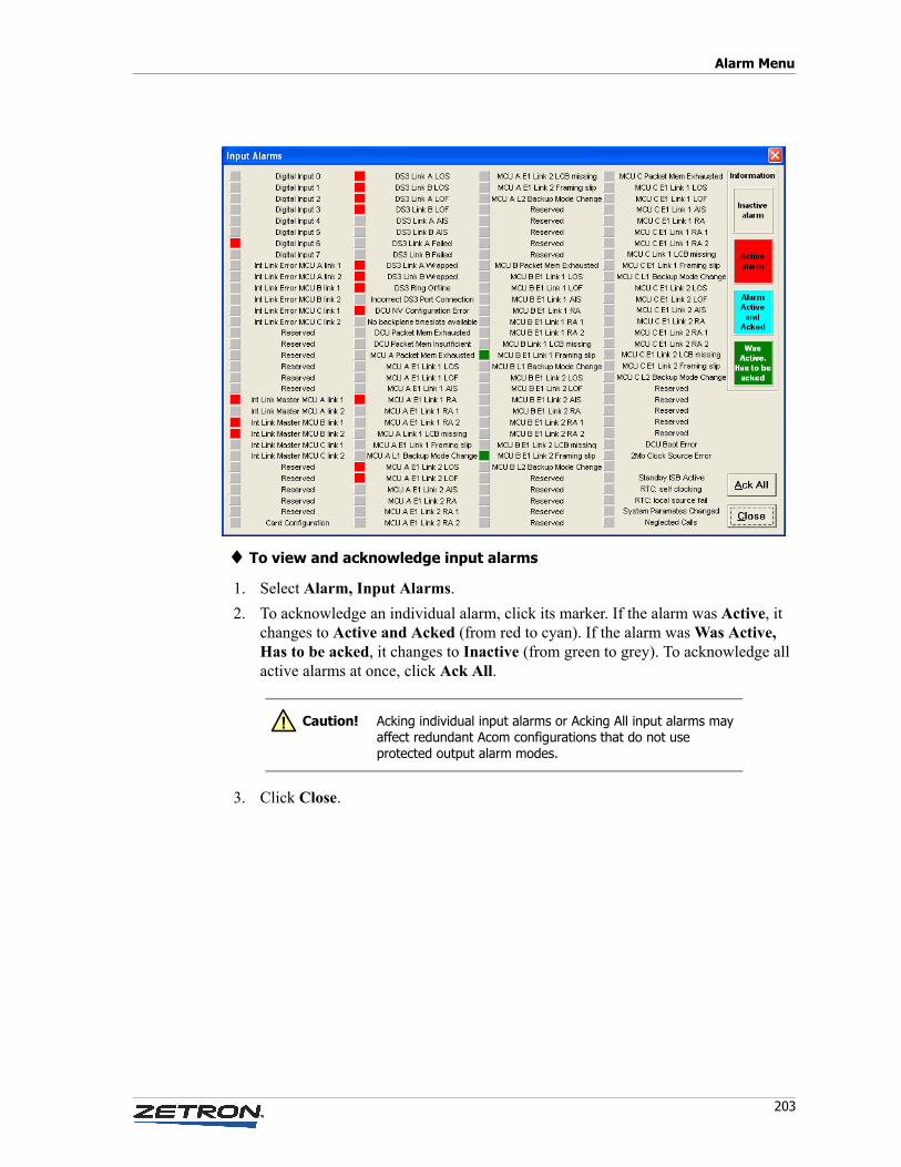
203
Alarm Menu
♦ To view and acknowledge input alarms
1. Select Alarm, Input Alarms.
2. To acknowledge an individual alarm, click its marker. If the alarm was Active, it changes to Active and Acked (from red to cyan). If the alarm was Was Active, Has to be acked, it changes to Inactive (from green to grey). To acknowledge all active alarms at once, click Ack All.
3. Click Close.
Caution! Acking individual input alarms or Acking All input alarms may affect redundant Acom configurations that do not use protected output alarm modes.
!
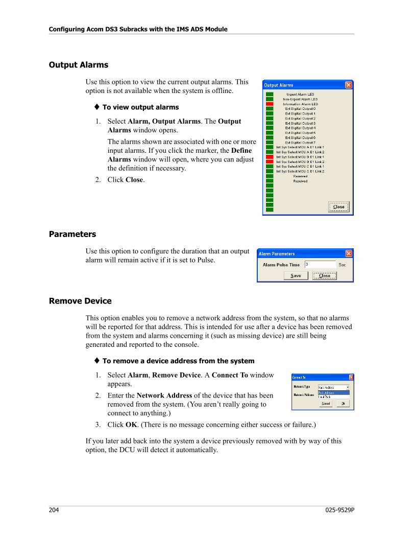
Configuring Acom DS3 Subracks with the IMS ADS Module
204 025-9529P
Output Alarms
Use this option to view the current output alarms. This option is not available when the system is offline.
♦ To view output alarms
1. Select Alarm, Output Alarms. The Output Alarms window opens.
The alarms shown are associated with one or more input alarms. If you click the marker, the Define Alarms window will open, where you can adjust the definition if necessary.
2. Click Close.
Parameters
Use this option to configure the duration that an output alarm will remain active if it is set to Pulse.
Remove Device
This option enables you to remove a network address from the system, so that no alarms will be reported for that address. This is intended for use after a device has been removed from the system and alarms concerning it (such as missing device) are still being generated and reported to the console.
♦ To remove a device address from the system
1. Select Alarm, Remove Device. A Connect To window appears.
2. Enter the Network Address of the device that has been removed from the system. (You aren’t really going to connect to anything.)
3. Click OK. (There is no message concerning either success or failure.)
If you later add back into the system a device previously removed with by way of this option, the DCU will detect it automatically.
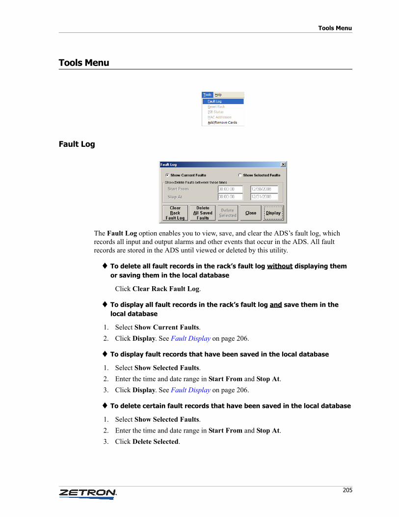
205
Tools Menu
Tools Menu
Fault Log
The Fault Log option enables you to view, save, and clear the ADS’s fault log, which records all input and output alarms and other events that occur in the ADS. All fault records are stored in the ADS until viewed or deleted by this utility.
♦ To delete all fault records in the rack’s fault log without displaying them or saving them in the local database
Click Clear Rack Fault Log.
♦ To display all fault records in the rack’s fault log and save them in the local database
1. Select Show Current Faults.
2. Click Display. See Fault Display on page 206.
♦ To display fault records that have been saved in the local database
1. Select Show Selected Faults.
2. Enter the time and date range in Start From and Stop At.
3. Click Display. See Fault Display on page 206.
♦ To delete certain fault records that have been saved in the local database
1. Select Show Selected Faults.
2. Enter the time and date range in Start From and Stop At.
3. Click Delete Selected.
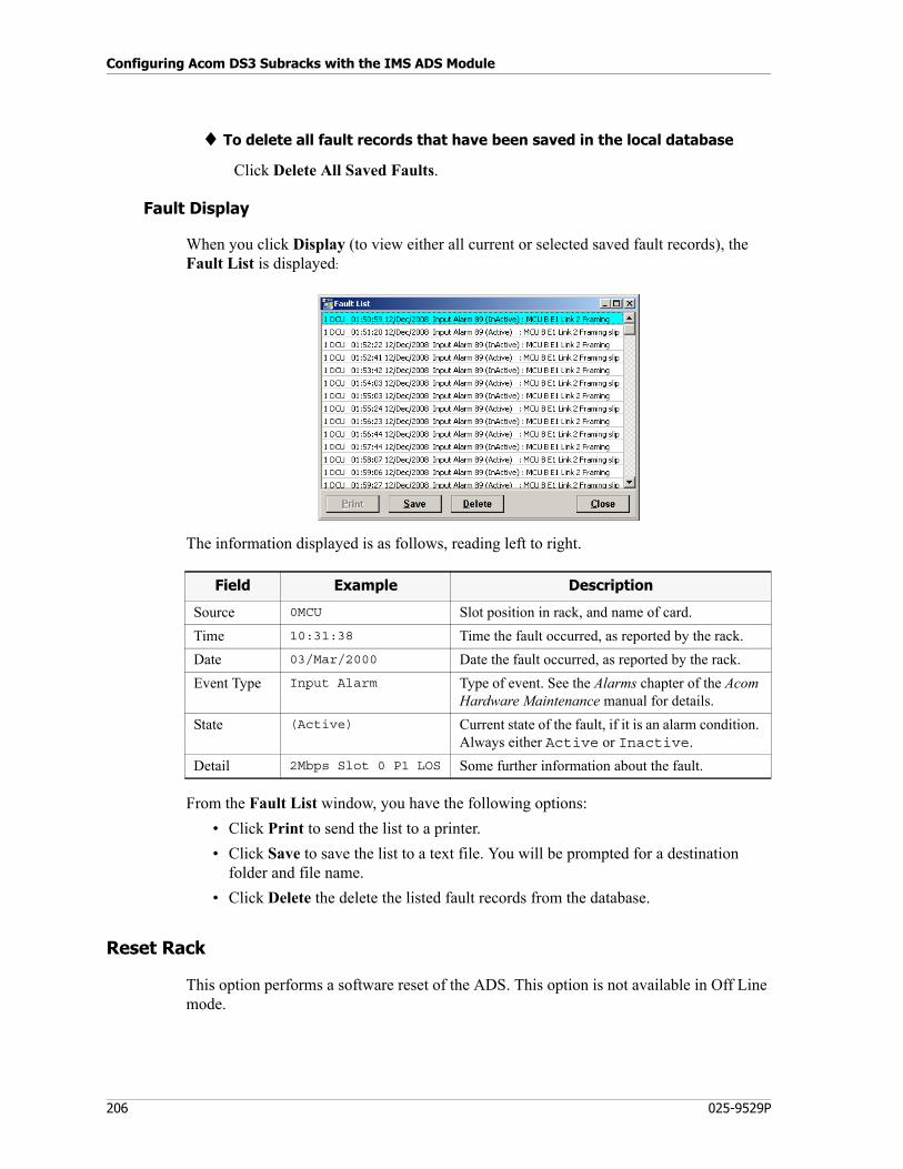
Configuring Acom DS3 Subracks with the IMS ADS Module
206 025-9529P
♦ To delete all fault records that have been saved in the local database
Click Delete All Saved Faults.
Fault Display
When you click Display (to view either all current or selected saved fault records), the Fault List is displayed:
The information displayed is as follows, reading left to right.
From the Fault List window, you have the following options:
• Click Print to send the list to a printer.
• Click Save to save the list to a text file. You will be prompted for a destination folder and file name.
• Click Delete the delete the listed fault records from the database.
Reset Rack
This option performs a software reset of the ADS. This option is not available in Off Line mode.
Field Example Description
Source 0MCU Slot position in rack, and name of card.
Time 10:31:38 Time the fault occurred, as reported by the rack.
Date 03/Mar/2000 Date the fault occurred, as reported by the rack.
Event Type Input Alarm Type of event. See the Alarms chapter of the Acom Hardware Maintenance manual for details.
State (Active) Current state of the fault, if it is an alarm condition. Always either Active or Inactive.
Detail 2Mbps Slot 0 P1 LOS Some further information about the fault.
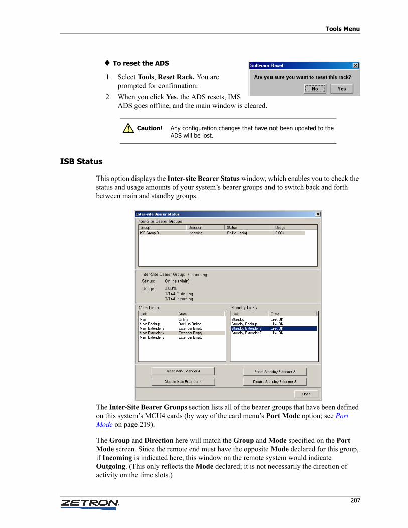
207
Tools Menu
♦ To reset the ADS
1. Select Tools, Reset Rack. You are prompted for confirmation.
2. When you click Yes, the ADS resets, IMS ADS goes offline, and the main window is cleared.
ISB Status
This option displays the Inter-site Bearer Status window, which enables you to check the status and usage amounts of your system’s bearer groups and to switch back and forth between main and standby groups.
The Inter-Site Bearer Groups section lists all of the bearer groups that have been defined on this system’s MCU4 cards (by way of the card menu’s Port Mode option; see Port Mode on page 219).
The Group and Direction here will match the Group and Mode specified on the Port Mode screen. Since the remote end must have the opposite Mode declared for this group, if Incoming is indicated here, this window on the remote system would indicate Outgoing. (This only reflects the Mode declared; it is not necessarily the direction of activity on the time slots.)
Caution! Any configuration changes that have not been updated to the ADS will be lost.
!
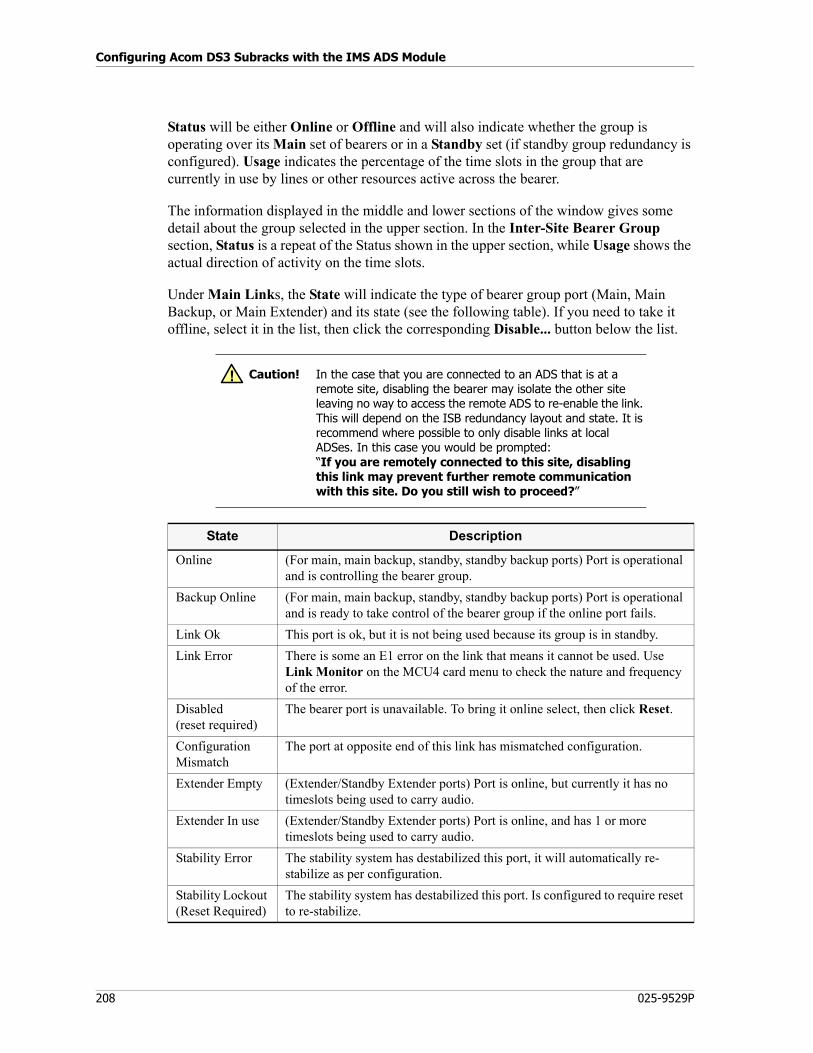
Configuring Acom DS3 Subracks with the IMS ADS Module
208 025-9529P
Status will be either Online or Offline and will also indicate whether the group is operating over its Main set of bearers or in a Standby set (if standby group redundancy is configured). Usage indicates the percentage of the time slots in the group that are currently in use by lines or other resources active across the bearer.
The information displayed in the middle and lower sections of the window gives some detail about the group selected in the upper section. In the Inter-Site Bearer Group section, Status is a repeat of the Status shown in the upper section, while Usage shows the actual direction of activity on the time slots.
Under Main Links, the State will indicate the type of bearer group port (Main, Main Backup, or Main Extender) and its state (see the following table). If you need to take it offline, select it in the list, then click the corresponding Disable... button below the list.
Caution! In the case that you are connected to an ADS that is at a remote site, disabling the bearer may isolate the other site leaving no way to access the remote ADS to re-enable the link. This will depend on the ISB redundancy layout and state. It is recommend where possible to only disable links at local ADSes. In this case you would be prompted:“If you are remotely connected to this site, disabling this link may prevent further remote communication with this site. Do you still wish to proceed?”
State Description
Online (For main, main backup, standby, standby backup ports) Port is operational and is controlling the bearer group.
Backup Online (For main, main backup, standby, standby backup ports) Port is operational and is ready to take control of the bearer group if the online port fails.
Link Ok This port is ok, but it is not being used because its group is in standby.
Link Error There is some an E1 error on the link that means it cannot be used. Use Link Monitor on the MCU4 card menu to check the nature and frequency of the error.
Disabled(reset required)
The bearer port is unavailable. To bring it online select, then click Reset.
Configuration Mismatch
The port at opposite end of this link has mismatched configuration.
Extender Empty (Extender/Standby Extender ports) Port is online, but currently it has no timeslots being used to carry audio.
Extender In use (Extender/Standby Extender ports) Port is online, and has 1 or more timeslots being used to carry audio.
Stability Error The stability system has destabilized this port, it will automatically re-stabilize as per configuration.
Stability Lockout (Reset Required)
The stability system has destabilized this port. Is configured to require reset to re-stabilize.
!
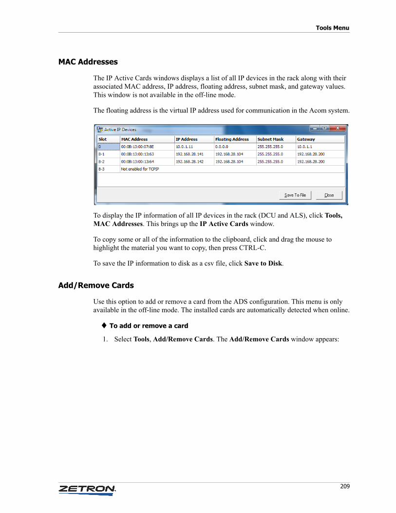
209
Tools Menu
MAC Addresses
The IP Active Cards windows displays a list of all IP devices in the rack along with their associated MAC address, IP address, floating address, subnet mask, and gateway values. This window is not available in the off-line mode.
The floating address is the virtual IP address used for communication in the Acom system.
To display the IP information of all IP devices in the rack (DCU and ALS), click Tools, MAC Addresses. This brings up the IP Active Cards window.
To copy some or all of the information to the clipboard, click and drag the mouse to highlight the material you want to copy, then press CTRL-C.
To save the IP information to disk as a csv file, click Save to Disk.
Add/Remove Cards
Use this option to add or remove a card from the ADS configuration. This menu is only available in the off-line mode. The installed cards are automatically detected when online.
♦ To add or remove a card
1. Select Tools, Add/Remove Cards. The Add/Remove Cards window appears:
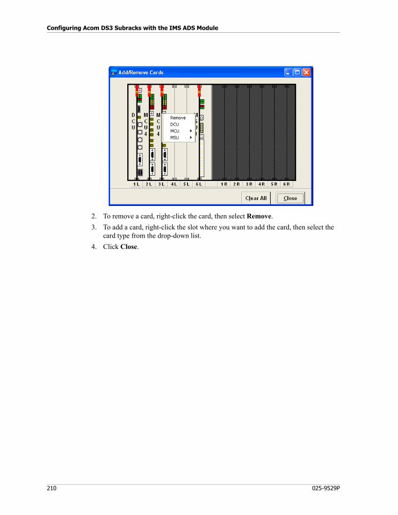
Configuring Acom DS3 Subracks with the IMS ADS Module
210 025-9529P
2. To remove a card, right-click the card, then select Remove.
3. To add a card, right-click the slot where you want to add the card, then select the card type from the drop-down list.
4. Click Close.
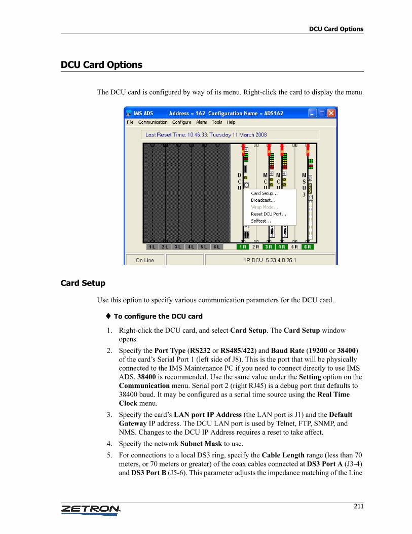
211
DCU Card Options
DCU Card Options
The DCU card is configured by way of its menu. Right-click the card to display the menu.
Card Setup
Use this option to specify various communication parameters for the DCU card.
♦ To configure the DCU card
1. Right-click the DCU card, and select Card Setup. The Card Setup window opens.
2. Specify the Port Type (RS232 or RS485/422) and Baud Rate (19200 or 38400) of the card’s Serial Port 1 (left side of J8). This is the port that will be physically connected to the IMS Maintenance PC if you need to connect directly to use IMS ADS. 38400 is recommended. Use the same value under the Setting option on the Communication menu. Serial port 2 (right RJ45) is a debug port that defaults to 38400 baud. It may be configured as a serial time source using the Real Time Clock menu.
3. Specify the card’s LAN port IP Address (the LAN port is J1) and the Default Gateway IP address. The DCU LAN port is used by Telnet, FTP, SNMP, and NMS. Changes to the DCU IP Address requires a reset to take affect.
4. Specify the network Subnet Mask to use.
5. For connections to a local DS3 ring, specify the Cable Length range (less than 70 meters, or 70 meters or greater) of the coax cables connected at DS3 Port A (J3-4) and DS3 Port B (J5-6). This parameter adjusts the impedance matching of the Line
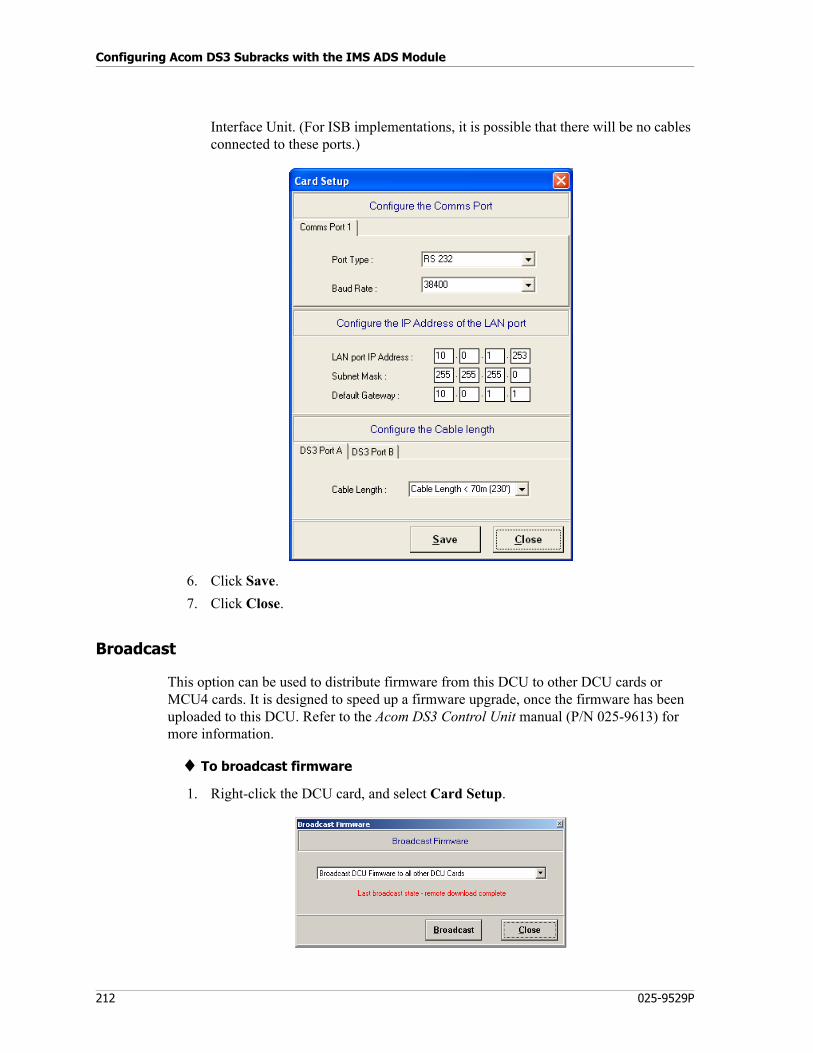
Configuring Acom DS3 Subracks with the IMS ADS Module
212 025-9529P
Interface Unit. (For ISB implementations, it is possible that there will be no cables connected to these ports.)
6. Click Save.
7. Click Close.
Broadcast
This option can be used to distribute firmware from this DCU to other DCU cards or MCU4 cards. It is designed to speed up a firmware upgrade, once the firmware has been uploaded to this DCU. Refer to the Acom DS3 Control Unit manual (P/N 025-9613) for more information.
♦ To broadcast firmware
1. Right-click the DCU card, and select Card Setup.
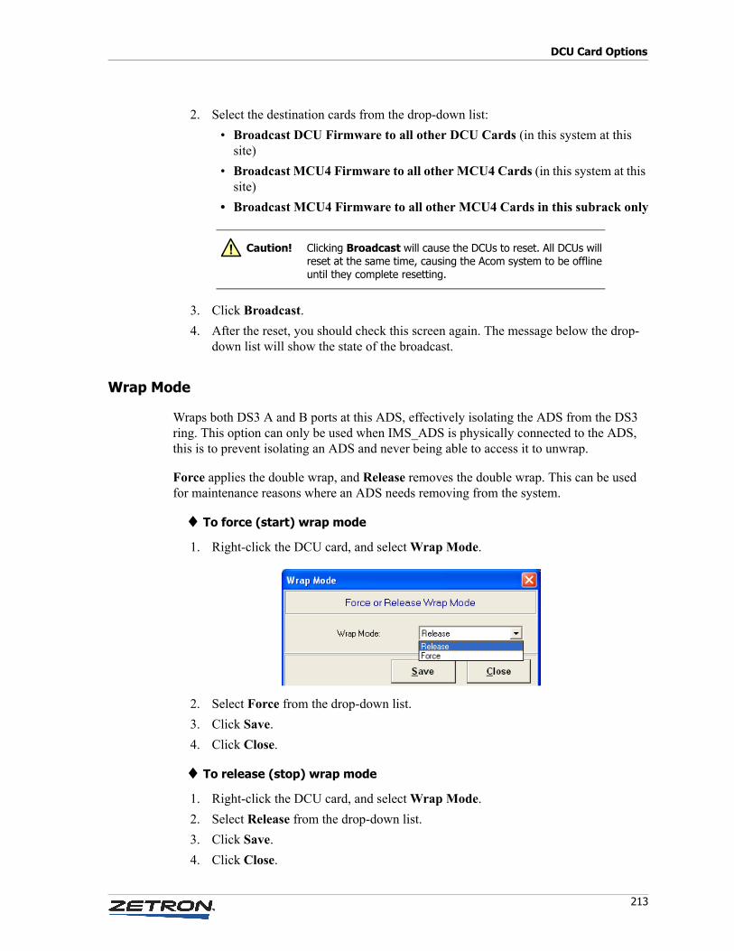
213
DCU Card Options
2. Select the destination cards from the drop-down list:
• Broadcast DCU Firmware to all other DCU Cards (in this system at this site)
• Broadcast MCU4 Firmware to all other MCU4 Cards (in this system at this site)
• Broadcast MCU4 Firmware to all other MCU4 Cards in this subrack only
3. Click Broadcast.
4. After the reset, you should check this screen again. The message below the drop-down list will show the state of the broadcast.
Wrap Mode
Wraps both DS3 A and B ports at this ADS, effectively isolating the ADS from the DS3 ring. This option can only be used when IMS_ADS is physically connected to the ADS, this is to prevent isolating an ADS and never being able to access it to unwrap.
Force applies the double wrap, and Release removes the double wrap. This can be used for maintenance reasons where an ADS needs removing from the system.
♦ To force (start) wrap mode
1. Right-click the DCU card, and select Wrap Mode.
2. Select Force from the drop-down list.
3. Click Save.
4. Click Close.
♦ To release (stop) wrap mode
1. Right-click the DCU card, and select Wrap Mode.
2. Select Release from the drop-down list.
3. Click Save.
4. Click Close.
Caution! Clicking Broadcast will cause the DCUs to reset. All DCUs will reset at the same time, causing the Acom system to be offline until they complete resetting.
!
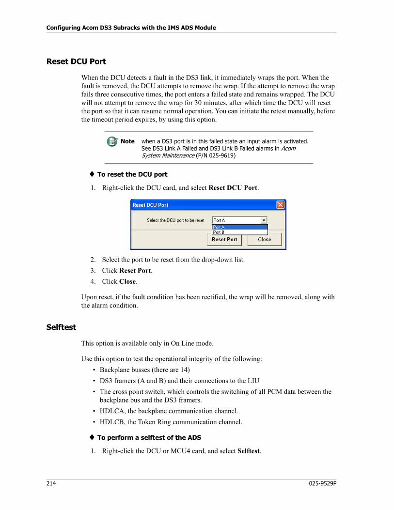
Configuring Acom DS3 Subracks with the IMS ADS Module
214 025-9529P
Reset DCU Port
When the DCU detects a fault in the DS3 link, it immediately wraps the port. When the fault is removed, the DCU attempts to remove the wrap. If the attempt to remove the wrap fails three consecutive times, the port enters a failed state and remains wrapped. The DCU will not attempt to remove the wrap for 30 minutes, after which time the DCU will reset the port so that it can resume normal operation. You can initiate the retest manually, before the timeout period expires, by using this option.
♦ To reset the DCU port
1. Right-click the DCU card, and select Reset DCU Port.
2. Select the port to be reset from the drop-down list.
3. Click Reset Port.
4. Click Close.
Upon reset, if the fault condition has been rectified, the wrap will be removed, along with the alarm condition.
Selftest
This option is available only in On Line mode.
Use this option to test the operational integrity of the following:
• Backplane busses (there are 14)
• DS3 framers (A and B) and their connections to the LIU
• The cross point switch, which controls the switching of all PCM data between the backplane bus and the DS3 framers.
• HDLCA, the backplane communication channel.
• HDLCB, the Token Ring communication channel.
♦ To perform a selftest of the ADS
1. Right-click the DCU or MCU4 card, and select Selftest.
Note when a DS3 port is in this failed state an input alarm is activated. See DS3 Link A Failed and DS3 Link B Failed alarms in Acom System Maintenance (P/N 025-9619)
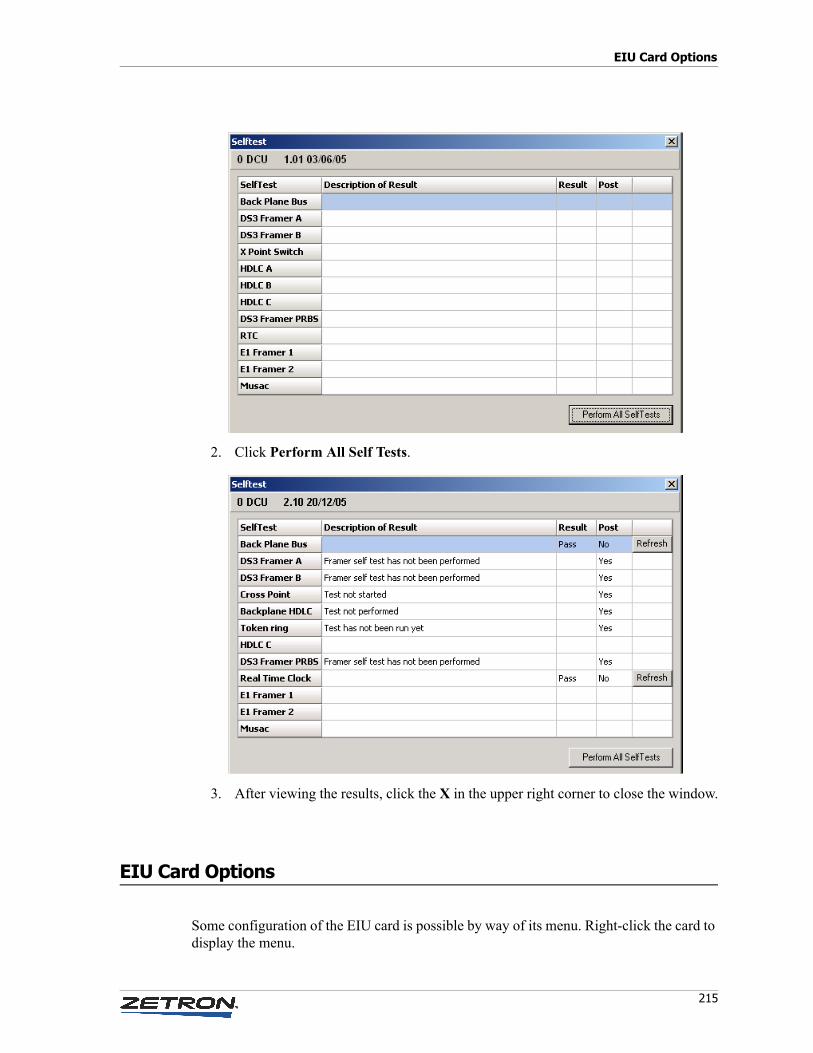
215
EIU Card Options
2. Click Perform All Self Tests.
3. After viewing the results, click the X in the upper right corner to close the window.
EIU Card Options
Some configuration of the EIU card is possible by way of its menu. Right-click the card to display the menu.
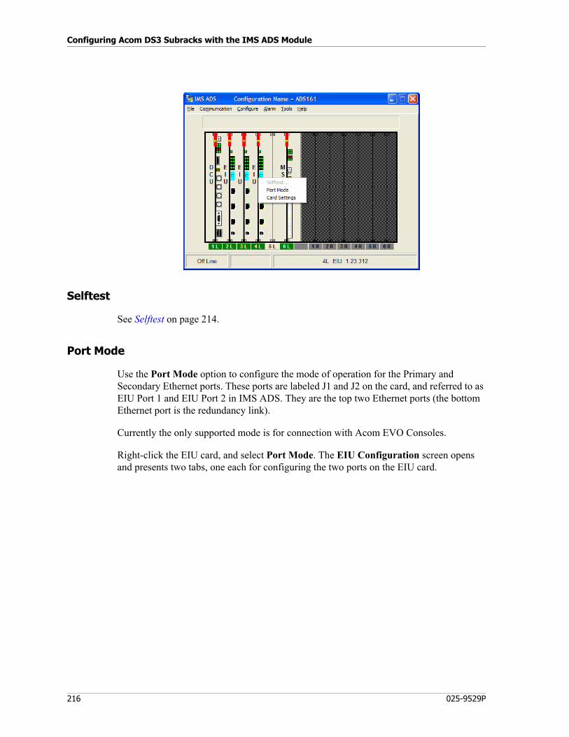
Configuring Acom DS3 Subracks with the IMS ADS Module
216 025-9529P
Selftest
See Selftest on page 214.
Port Mode
Use the Port Mode option to configure the mode of operation for the Primary and Secondary Ethernet ports. These ports are labeled J1 and J2 on the card, and referred to as EIU Port 1 and EIU Port 2 in IMS ADS. They are the top two Ethernet ports (the bottom Ethernet port is the redundancy link).
Currently the only supported mode is for connection with Acom EVO Consoles.
Right-click the EIU card, and select Port Mode. The EIU Configuration screen opens and presents two tabs, one each for configuring the two ports on the EIU card.
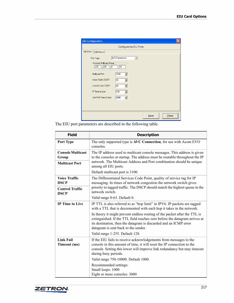
217
EIU Card Options
The EIU port parameters are described in the following table.
Field Description
Port Type The only supported type is AVC Connection, for use with Acom EVO consoles.
Console Multicast Group
The IP address used to multicast console messages. This address is given to the consoles at startup. The address must be routable throughout the IP network. The Multicast Address and Port combination should be unique among all EIU ports.
Default multicast port is 3100.
Multicast Port
Voice Traffic DSCP
The Differentiated Services Code Point, quality of service tag for IP messaging. In times of network congestion the network switch gives priority to tagged traffic. The DSCP should match the highest queue in the network switch.
Valid range 0-63. Default 0.
Control Traffic DSCP
IP Time to Live IP TTL is also referred to as “hop limit” in IPV6. IP packets are tagged with a TTL that is decremented with each hop it takes in the network.
In theory it might prevent endless routing of the packet after the TTL is extinguished. If the TTL field reaches zero before the datagram arrives at its destination, then the datagram is discarded and an ICMP error datagram is sent back to the sender.
Valid range 1-255. Default 128.
Link Fail Timeout (ms)
If the EIU fails to receive acknowledgements from messages to the console in this amount of time, it will reset the IP connection to the console. Setting this lower will improve link redundancy but may timeout during busy periods.
Valid range 750-10000. Default 1000.
Recommended settings:Small loops: 1000Eight or more consoles: 3000
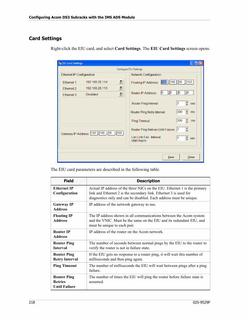
Configuring Acom DS3 Subracks with the IMS ADS Module
218 025-9529P
Card Settings
Right-click the EIU card, and select Card Settings. The EIU Card Settings screen opens.
The EIU card parameters are described in the following table.
Field Description
Ethernet IP Configuration
Actual IP address of the three NICs on the EIU. Ethernet 1 is the primary link and Ethernet 2 is the secondary link. Ethernet 3 is used for diagnostics only and can be disabled. Each address must be unique.
Gateway IP Address
IP address of the network gateway to use.
Floating IP Address
The IP address shown in all communications between the Acom system and the VNIC. Must be the same on the EIU and its redundant EIU, and must be unique to each pair.
Router IP Address
IP address of the router on the Acom network.
Router Ping Interval
The number of seconds between normal pings by the EIU to the router to verify the router is not in failure state.
Router Ping Retry Interval
If the EIU gets no response to a router ping, it will wait this number of milliseconds and then ping again.
Ping Timeout The number of milliseconds the EIU will wait between pings after a ping failure.
Router Ping Retries Until Failure
The number of times the EIU will ping the router before failure state is assumed.
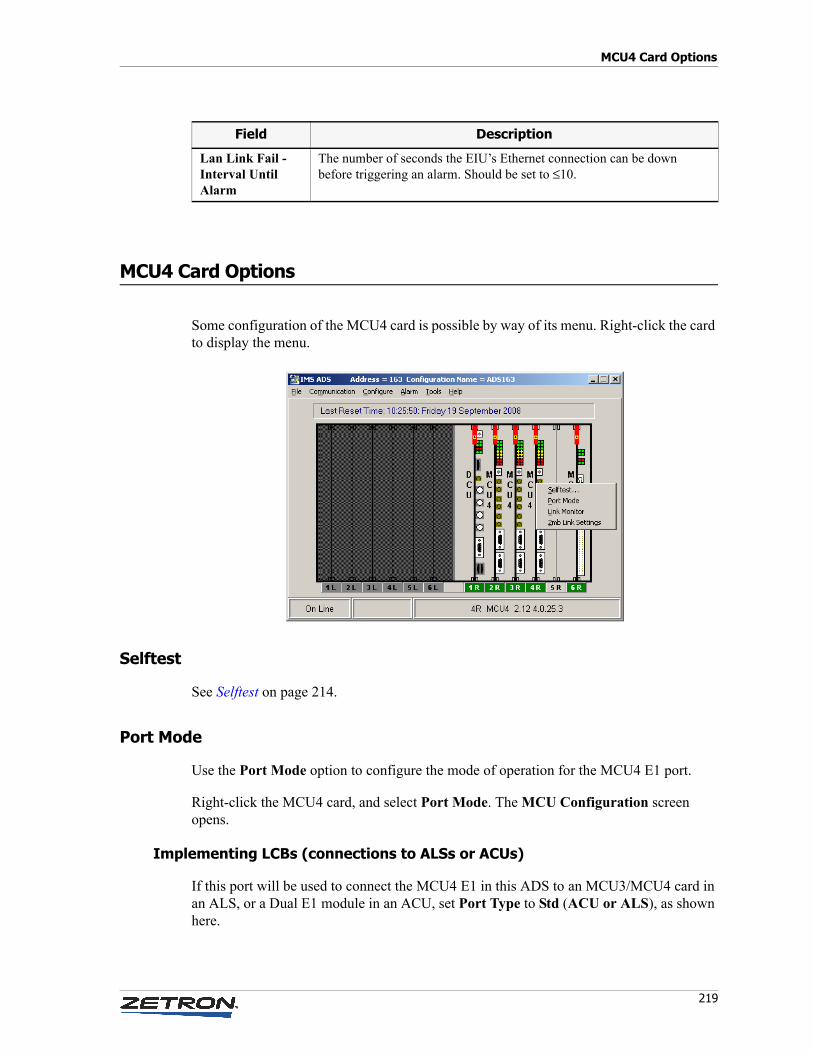
219
MCU4 Card Options
MCU4 Card Options
Some configuration of the MCU4 card is possible by way of its menu. Right-click the card to display the menu.
Selftest
See Selftest on page 214.
Port Mode
Use the Port Mode option to configure the mode of operation for the MCU4 E1 port.
Right-click the MCU4 card, and select Port Mode. The MCU Configuration screen opens.
Implementing LCBs (connections to ALSs or ACUs)
If this port will be used to connect the MCU4 E1 in this ADS to an MCU3/MCU4 card in an ALS, or a Dual E1 module in an ACU, set Port Type to Std (ACU or ALS), as shown here.
Lan Link Fail - Interval Until Alarm
The number of seconds the EIU’s Ethernet connection can be down before triggering an alarm. Should be set to ≤10.
Field Description
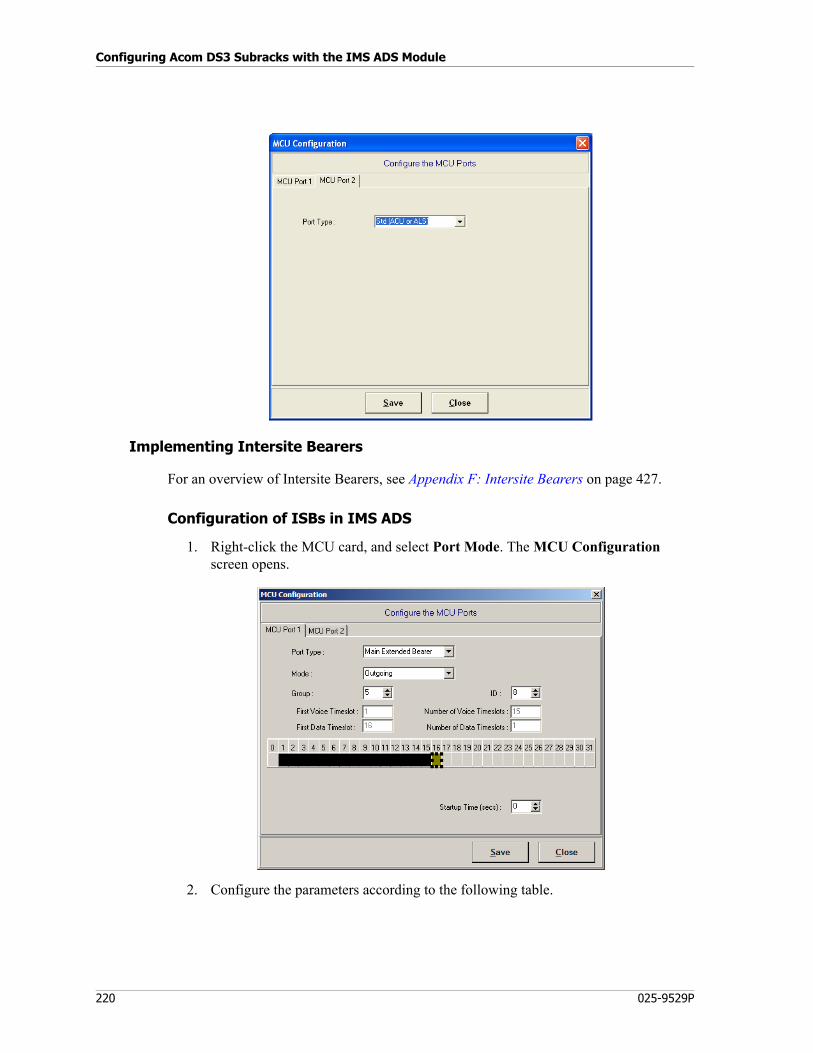
Configuring Acom DS3 Subracks with the IMS ADS Module
220 025-9529P
Implementing Intersite Bearers
For an overview of Intersite Bearers, see Appendix F: Intersite Bearers on page 427.
Configuration of ISBs in IMS ADS
1. Right-click the MCU card, and select Port Mode. The MCU Configuration screen opens.
2. Configure the parameters according to the following table.
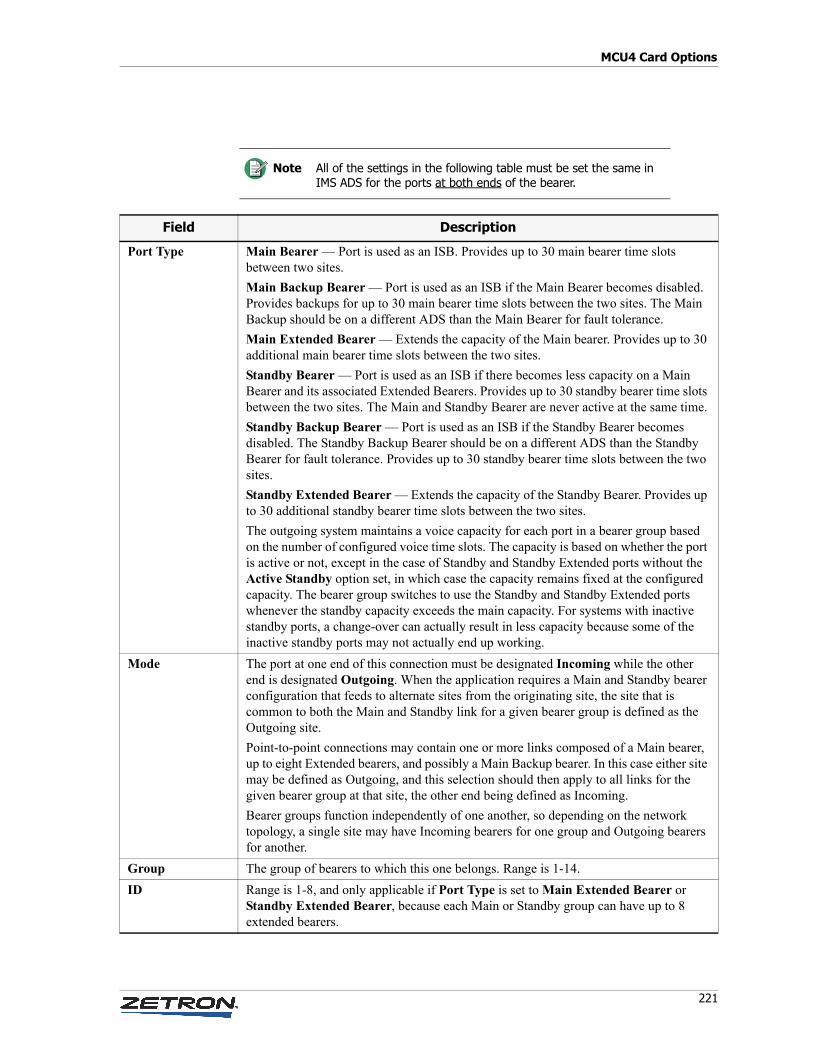
221
MCU4 Card Options
Note All of the settings in the following table must be set the same in IMS ADS for the ports at both ends of the bearer.
Field Description
Port Type Main Bearer — Port is used as an ISB. Provides up to 30 main bearer time slots between two sites.
Main Backup Bearer — Port is used as an ISB if the Main Bearer becomes disabled. Provides backups for up to 30 main bearer time slots between the two sites. The Main Backup should be on a different ADS than the Main Bearer for fault tolerance.
Main Extended Bearer — Extends the capacity of the Main bearer. Provides up to 30 additional main bearer time slots between the two sites.
Standby Bearer — Port is used as an ISB if there becomes less capacity on a Main Bearer and its associated Extended Bearers. Provides up to 30 standby bearer time slots between the two sites. The Main and Standby Bearer are never active at the same time.
Standby Backup Bearer — Port is used as an ISB if the Standby Bearer becomes disabled. The Standby Backup Bearer should be on a different ADS than the Standby Bearer for fault tolerance. Provides up to 30 standby bearer time slots between the two sites.
Standby Extended Bearer — Extends the capacity of the Standby Bearer. Provides up to 30 additional standby bearer time slots between the two sites.
The outgoing system maintains a voice capacity for each port in a bearer group based on the number of configured voice time slots. The capacity is based on whether the port is active or not, except in the case of Standby and Standby Extended ports without the Active Standby option set, in which case the capacity remains fixed at the configured capacity. The bearer group switches to use the Standby and Standby Extended ports whenever the standby capacity exceeds the main capacity. For systems with inactive standby ports, a change-over can actually result in less capacity because some of the inactive standby ports may not actually end up working.
Mode The port at one end of this connection must be designated Incoming while the other end is designated Outgoing. When the application requires a Main and Standby bearer configuration that feeds to alternate sites from the originating site, the site that is common to both the Main and Standby link for a given bearer group is defined as the Outgoing site.
Point-to-point connections may contain one or more links composed of a Main bearer, up to eight Extended bearers, and possibly a Main Backup bearer. In this case either site may be defined as Outgoing, and this selection should then apply to all links for the given bearer group at that site, the other end being defined as Incoming.
Bearer groups function independently of one another, so depending on the network topology, a single site may have Incoming bearers for one group and Outgoing bearers for another.
Group The group of bearers to which this one belongs. Range is 1-14.
ID Range is 1-8, and only applicable if Port Type is set to Main Extended Bearer or Standby Extended Bearer, because each Main or Standby group can have up to 8 extended bearers.
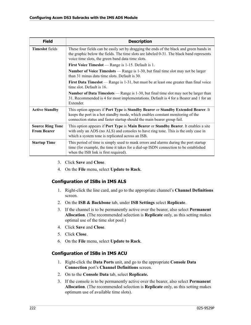
Configuring Acom DS3 Subracks with the IMS ADS Module
222 025-9529P
3. Click Save and Close.
4. On the File menu, select Update to Rack.
Configuration of ISBs in IMS ALS
1. Right-click the line card, and go to the appropriate channel’s Channel Definitions screen.
2. On the ISB & Backbone tab, under ISB Settings select Replicate.
3. If the channel is to be permanently active over the bearer, also select Permanent Allocation. (The recommended selection is Replicate only, as this setting makes optimal use of the time slot pool.)
4. Click Save and Close.
5. Click Close.
6. On the File menu, select Update to Rack.
Configuration of ISBs in IMS ACU
1. Right-click the Data Ports unit, and go to the appropriate Console Data Connection port’s Channel Definitions screen.
2. On to the Console Data tab, select Replicate.
3. If the console is to be permanently active over the bearer, also select Permanent Allocation. (The recommended selection is Replicate only, as this setting makes optimum use of available time slots).
Timeslot fields These four fields can be easily set by dragging the ends of the black and green bands in the graphic below the fields. The time slots are labeled 0-31. The black band represents voice time slots, the green band data time slots.
First Voice Timeslot — Range is 1-15. Default is 1.
Number of Voice Timeslots — Range is 1-30, but final time slot may not be larger than 31 minus data time slots. Default is 30.
First Data Timeslot — Range is 1-31, but must be at least one greater than final voice time slot. Default is 16.
Number of Data Timeslots — Range is 1-30, but final time slot may not be larger than 31. Recommended is 4 for most implementations. Default is 4 for a Bearer and 1 for an Extender.
Active Standby This option appears if Port Type is Standby Bearer or Standby Extended Bearer. It keeps the port in a hot standby mode, which enables constant monitoring of the connection status and faster startup should the main bearer group fail.
Source Ring ToneFrom Bearer
This option appears if Port Type is Main Bearer or Standby Bearer. It enables a site with only an ADS (no ALS) and consoles to have ring tone. This is the only case in which a system tone is replicated across an ISB.
Startup Time This period of time is simply used to mask errors and alarms during the port startup time (for example, the time it takes for a dial-up ISDN connection to be established when the ISB link is first required).
Field Description
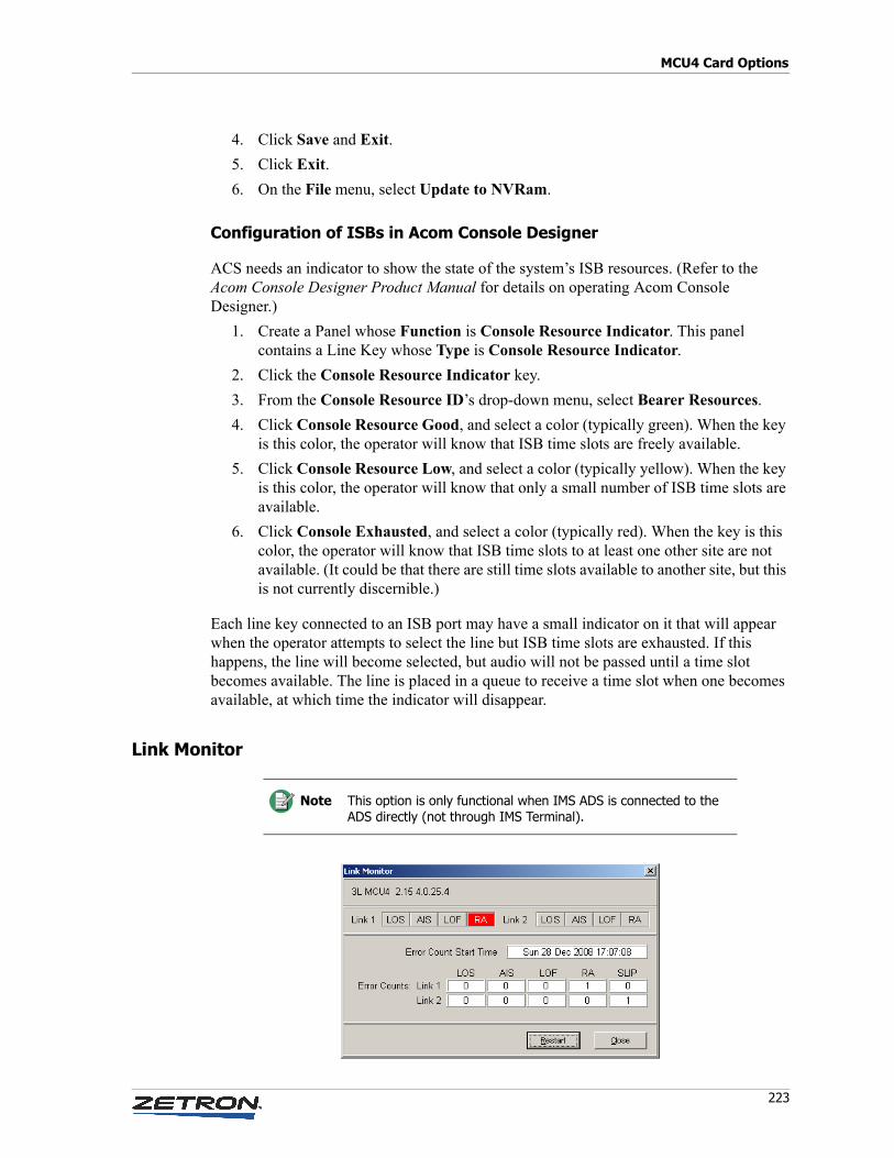
223
MCU4 Card Options
4. Click Save and Exit.
5. Click Exit.
6. On the File menu, select Update to NVRam.
Configuration of ISBs in Acom Console Designer
ACS needs an indicator to show the state of the system’s ISB resources. (Refer to the Acom Console Designer Product Manual for details on operating Acom Console Designer.)
1. Create a Panel whose Function is Console Resource Indicator. This panel contains a Line Key whose Type is Console Resource Indicator.
2. Click the Console Resource Indicator key.
3. From the Console Resource ID’s drop-down menu, select Bearer Resources.
4. Click Console Resource Good, and select a color (typically green). When the key is this color, the operator will know that ISB time slots are freely available.
5. Click Console Resource Low, and select a color (typically yellow). When the key is this color, the operator will know that only a small number of ISB time slots are available.
6. Click Console Exhausted, and select a color (typically red). When the key is this color, the operator will know that ISB time slots to at least one other site are not available. (It could be that there are still time slots available to another site, but this is not currently discernible.)
Each line key connected to an ISB port may have a small indicator on it that will appear when the operator attempts to select the line but ISB time slots are exhausted. If this happens, the line will become selected, but audio will not be passed until a time slot becomes available. The line is placed in a queue to receive a time slot when one becomes available, at which time the indicator will disappear.
Link Monitor
Note This option is only functional when IMS ADS is connected to the ADS directly (not through IMS Terminal).
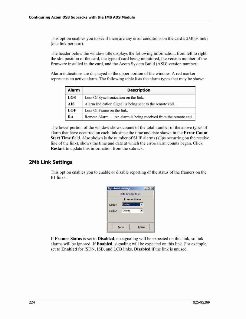
Configuring Acom DS3 Subracks with the IMS ADS Module
224 025-9529P
This option enables you to see if there are any error conditions on the card’s 2Mbps links (one link per port).
The header below the window title displays the following information, from left to right: the slot position of the card, the type of card being monitored, the version number of the firmware installed in the card, and the Acom System Build (ASB) version number.
Alarm indications are displayed in the upper portion of the window. A red marker represents an active alarm. The following table lists the alarm types that may be shown.
The lower portion of the window shows counts of the total number of the above types of alarm that have occurred on each link since the time and date shown in the Error Count Start Time field. Also shown is the number of SLIP alarms (slips occurring on the receive line of the link). shows the time and date at which the error/alarm counts began. Click Restart to update this information from the subrack.
2Mb Link Settings
This option enables you to enable or disable reporting of the status of the framers on the E1 links.
If Framer Status is set to Disabled, no signaling will be expected on this link, so link alarms will be ignored. If Enabled, signaling will be expected on this link. For example, set to Enabled for ISDN, ISB, and LCB links, Disabled if the link is unused.
Alarm Description
LOS Loss Of Synchronization on the link.
AIS Alarm Indication Signal is being sent to the remote end.
LOF Loss Of Frame on the link.
RA Remote Alarm — An alarm is being received from the remote end.
225
Configuring Acom Console Units with the IMS ACU Module
This chapter describes the ACU module of the Integrated Management System (IMS), software designed for configuring and managing standalone or networked Acom Console Units (ACUs) that are part of an Acom system.
In this chapter:
• Getting Started on page 226
• Managing Configurations (File Menu) on page 229
• Communicating with the ACU (Communication Menu) on page 230
• Configuring ACU Parameters (Configure Menu) on page 230
• Alarm Menu on page 238
• Tools Menu on page 243
• Data Ports Module on page 244
• Dual 4W E&M Module on page 250
• Dual E1 Module on page 254
• Operator’s Audio Module on page 263
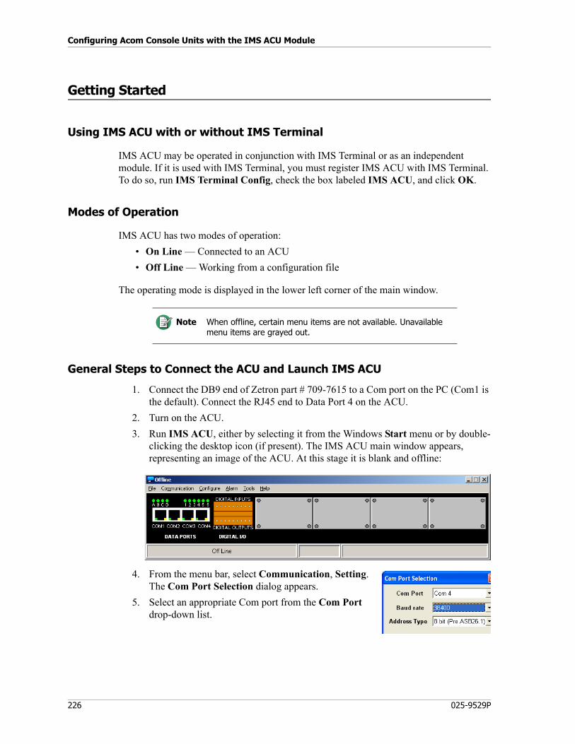
Configuring Acom Console Units with the IMS ACU Module
226 025-9529P
Getting Started
Using IMS ACU with or without IMS Terminal
IMS ACU may be operated in conjunction with IMS Terminal or as an independent module. If it is used with IMS Terminal, you must register IMS ACU with IMS Terminal. To do so, run IMS Terminal Config, check the box labeled IMS ACU, and click OK.
Modes of Operation
IMS ACU has two modes of operation:
• On Line — Connected to an ACU
• Off Line — Working from a configuration file
The operating mode is displayed in the lower left corner of the main window.
General Steps to Connect the ACU and Launch IMS ACU
1. Connect the DB9 end of Zetron part # 709-7615 to a Com port on the PC (Com1 is the default). Connect the RJ45 end to Data Port 4 on the ACU.
2. Turn on the ACU.
3. Run IMS ACU, either by selecting it from the Windows Start menu or by double-clicking the desktop icon (if present). The IMS ACU main window appears, representing an image of the ACU. At this stage it is blank and offline:
4. From the menu bar, select Communication, Setting. The Com Port Selection dialog appears.
5. Select an appropriate Com port from the Com Port drop-down list.
Note When offline, certain menu items are not available. Unavailable menu items are grayed out.
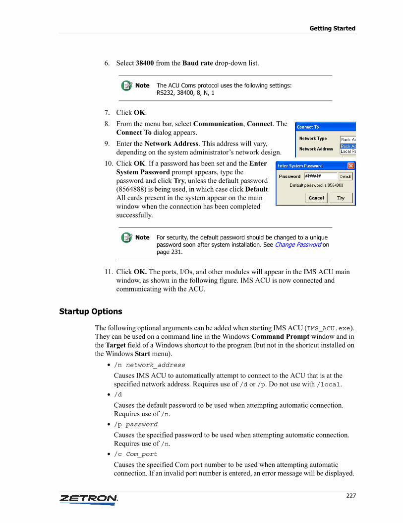
227
Getting Started
6. Select 38400 from the Baud rate drop-down list.
7. Click OK.
8. From the menu bar, select Communication, Connect. The Connect To dialog appears.
9. Enter the Network Address. This address will vary, depending on the system administrator’s network design.
10. Click OK. If a password has been set and the Enter System Password prompt appears, type the password and click Try, unless the default password (8564888) is being used, in which case click Default. All cards present in the system appear on the main window when the connection has been completed successfully.
11. Click OK. The ports, I/Os, and other modules will appear in the IMS ACU main window, as shown in the following figure. IMS ACU is now connected and communicating with the ACU.
Startup Options
The following optional arguments can be added when starting IMS ACU (IMS_ACU.exe). They can be used on a command line in the Windows Command Prompt window and in the Target field of a Windows shortcut to the program (but not in the shortcut installed on the Windows Start menu).
• /n network_address
Causes IMS ACU to automatically attempt to connect to the ACU that is at the specified network address. Requires use of /d or /p. Do not use with /local.
• /d
Causes the default password to be used when attempting automatic connection. Requires use of /n.
• /p password
Causes the specified password to be used when attempting automatic connection. Requires use of /n.
• /c Com_port
Causes the specified Com port number to be used when attempting automatic connection. If an invalid port number is entered, an error message will be displayed.
Note The ACU Coms protocol uses the following settings:RS232, 38400, 8, N, 1
Note For security, the default password should be changed to a unique password soon after system installation. See Change Password on page 231.
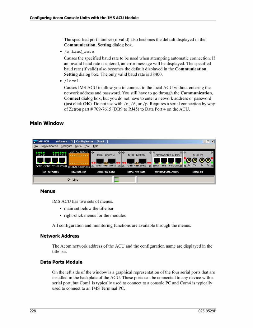
Configuring Acom Console Units with the IMS ACU Module
228 025-9529P
The specified port number (if valid) also becomes the default displayed in the Communication, Setting dialog box.
• /b baud_rate
Causes the specified baud rate to be used when attempting automatic connection. If an invalid baud rate is entered, an error message will be displayed. The specified baud rate (if valid) also becomes the default displayed in the Communication, Setting dialog box. The only valid baud rate is 38400.
• /local
Causes IMS ACU to allow you to connect to the local ACU without entering the network address and password. You still have to go through the Communication, Connect dialog box, but you do not have to enter a network address or password (just click OK). Do not use with /n, /d, or /p. Requires a serial connection by way of Zetron part # 709-7615 (DB9 to RJ45) to Data Port 4 on the ACU.
Main Window
Menus
IMS ACU has two sets of menus.
• main set below the title bar
• right-click menus for the modules
All configuration and monitoring functions are available through the menus.
Network Address
The Acom network address of the ACU and the configuration name are displayed in the title bar.
Data Ports Module
On the left side of the window is a graphical representation of the four serial ports that are installed in the backplate of the ACU. These ports can be connected to any device with a serial port, but Com1 is typically used to connect to a console PC and Com4 is typically used to connect to an IMS Terminal PC.
229
Managing Configurations (File Menu)
In the standard ACU, they are all RJ-45 ports and can be connected to any device with an RS232 or RS422 serial port. In the “3V” (newer) variant of the ACU, Com1 is a USB B-type port and can be connected to any device with a USB port.
Check or change configuration of the ports by way of the Data Ports module’s right-click menu. See Data Ports Module on page 244.
Digital I/O Module
Just to the right of the Data Ports graphic is a graphical representation of the digital inputs to and digital outputs from this ACU. Check or change configuration of digital inputs or outputs by way of the Digital I/O option on the Configure menu. See Digital I/O on page 234.
Other Modules
Up to four other modules, of the types listed below, can be installed in the ACU. They are illustrated in the rest of the window. Check or change configuration of these modules by way of their individual right-click menus. See these sections:
• Dual 4W E&M Module on page 250
• Dual E1 Module on page 254
• Operator’s Audio Module on page 263
Status/Hint Bar
The offline/online status of the ACU is shown in the left portion of the bottom part of the window. In the middle portion you may see a graphical bar, which indicates communication to/from the ACU. To help identify and validate ACU modules, a “hint” message will appear in the right portion as the mouse is passed over a module. It shows the module type, the module’s firmware version (if applicable), and the firmware release date (if applicable).
Managing Configurations (File Menu)
The File menu has the same functionality as does the File menu in IMS ADS, except that Update to NVRam in IMS ACU is called Update to Rack in IMS ADS. For usage, see Managing Configurations (File Menu) on page 178.
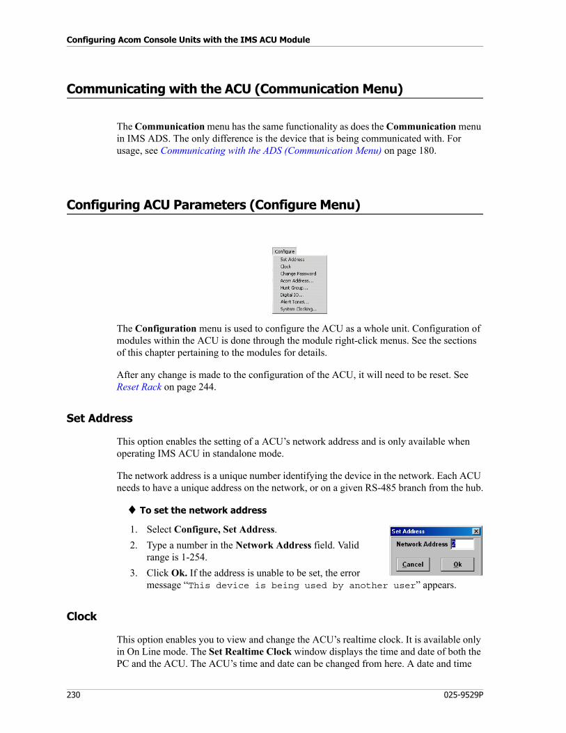
Configuring Acom Console Units with the IMS ACU Module
230 025-9529P
Communicating with the ACU (Communication Menu)
The Communication menu has the same functionality as does the Communication menu in IMS ADS. The only difference is the device that is being communicated with. For usage, see Communicating with the ADS (Communication Menu) on page 180.
Configuring ACU Parameters (Configure Menu)
The Configuration menu is used to configure the ACU as a whole unit. Configuration of modules within the ACU is done through the module right-click menus. See the sections of this chapter pertaining to the modules for details.
After any change is made to the configuration of the ACU, it will need to be reset. See Reset Rack on page 244.
Set Address
This option enables the setting of a ACU’s network address and is only available when operating IMS ACU in standalone mode.
The network address is a unique number identifying the device in the network. Each ACU needs to have a unique address on the network, or on a given RS-485 branch from the hub.
♦ To set the network address
1. Select Configure, Set Address.
2. Type a number in the Network Address field. Valid range is 1-254.
3. Click Ok. If the address is unable to be set, the error message “This device is being used by another user” appears.
Clock
This option enables you to view and change the ACU’s realtime clock. It is available only in On Line mode. The Set Realtime Clock window displays the time and date of both the PC and the ACU. The ACU’s time and date can be changed from here. A date and time
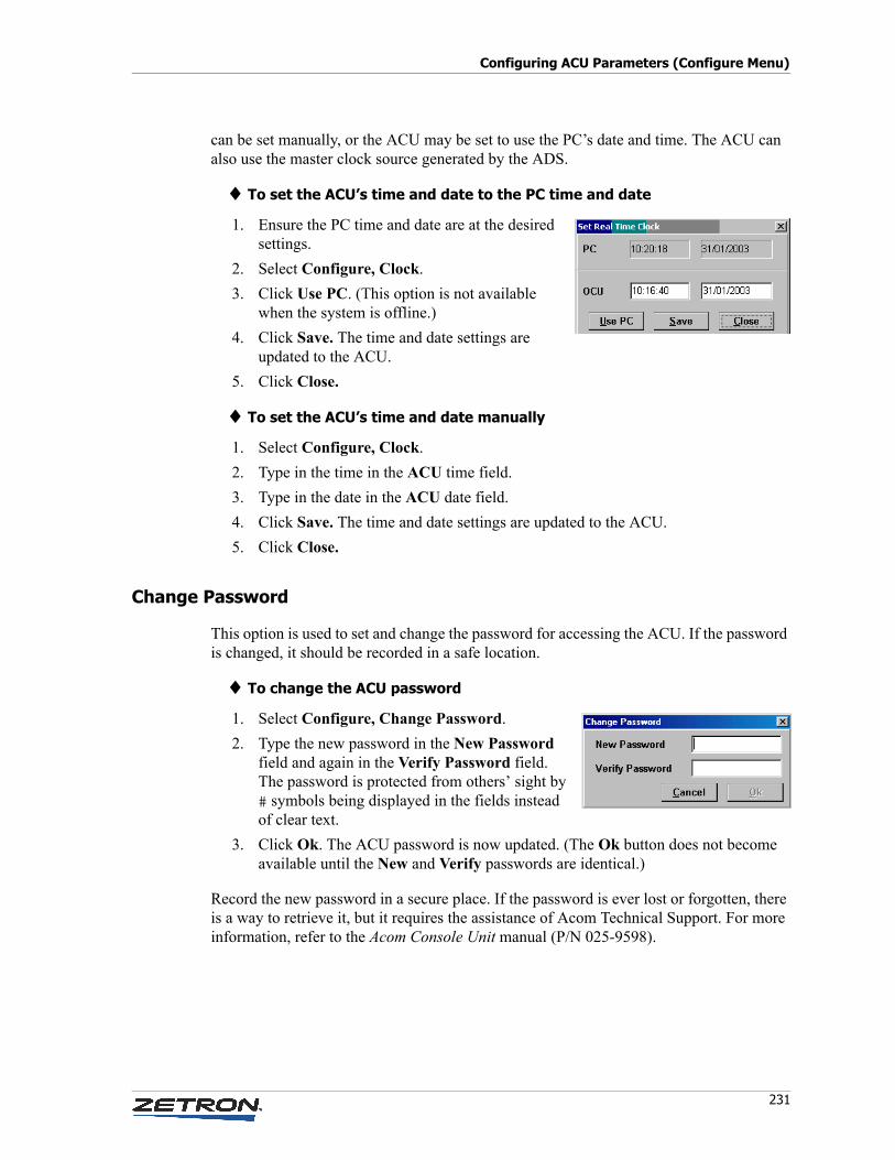
231
Configuring ACU Parameters (Configure Menu)
can be set manually, or the ACU may be set to use the PC’s date and time. The ACU can also use the master clock source generated by the ADS.
♦ To set the ACU’s time and date to the PC time and date
1. Ensure the PC time and date are at the desired settings.
2. Select Configure, Clock.
3. Click Use PC. (This option is not available when the system is offline.)
4. Click Save. The time and date settings are updated to the ACU.
5. Click Close.
♦ To set the ACU’s time and date manually
1. Select Configure, Clock.
2. Type in the time in the ACU time field.
3. Type in the date in the ACU date field.
4. Click Save. The time and date settings are updated to the ACU.
5. Click Close.
Change Password
This option is used to set and change the password for accessing the ACU. If the password is changed, it should be recorded in a safe location.
♦ To change the ACU password
1. Select Configure, Change Password.
2. Type the new password in the New Password field and again in the Verify Password field. The password is protected from others’ sight by # symbols being displayed in the fields instead of clear text.
3. Click Ok. The ACU password is now updated. (The Ok button does not become available until the New and Verify passwords are identical.)
Record the new password in a secure place. If the password is ever lost or forgotten, there is a way to retrieve it, but it requires the assistance of Acom Technical Support. For more information, refer to the Acom Console Unit manual (P/N 025-9598).
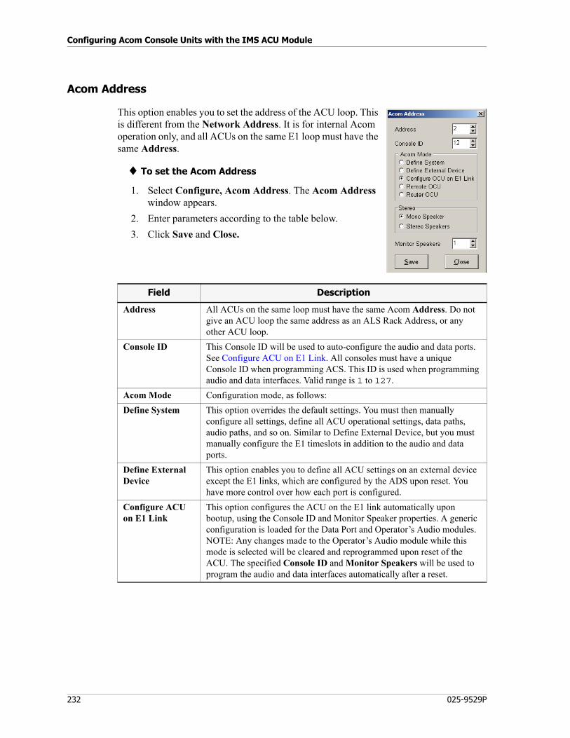
Configuring Acom Console Units with the IMS ACU Module
232 025-9529P
Acom Address
This option enables you to set the address of the ACU loop. This is different from the Network Address. It is for internal Acom operation only, and all ACUs on the same E1 loop must have the same Address.
♦ To set the Acom Address
1. Select Configure, Acom Address. The Acom Address window appears.
2. Enter parameters according to the table below.
3. Click Save and Close.
Field Description
Address All ACUs on the same loop must have the same Acom Address. Do not give an ACU loop the same address as an ALS Rack Address, or any other ACU loop.
Console ID This Console ID will be used to auto-configure the audio and data ports. See Configure ACU on E1 Link. All consoles must have a unique Console ID when programming ACS. This ID is used when programming audio and data interfaces. Valid range is 1 to 127.
Acom Mode Configuration mode, as follows:
Define System This option overrides the default settings. You must then manually configure all settings, define all ACU operational settings, data paths, audio paths, and so on. Similar to Define External Device, but you must manually configure the E1 timeslots in addition to the audio and data ports.
Define External Device
This option enables you to define all ACU settings on an external device except the E1 links, which are configured by the ADS upon reset. You have more control over how each port is configured.
Configure ACU on E1 Link
This option configures the ACU on the E1 link automatically upon bootup, using the Console ID and Monitor Speaker properties. A generic configuration is loaded for the Data Port and Operator’s Audio modules. NOTE: Any changes made to the Operator’s Audio module while this mode is selected will be cleared and reprogrammed upon reset of the ACU. The specified Console ID and Monitor Speakers will be used to program the audio and data interfaces automatically after a reset.
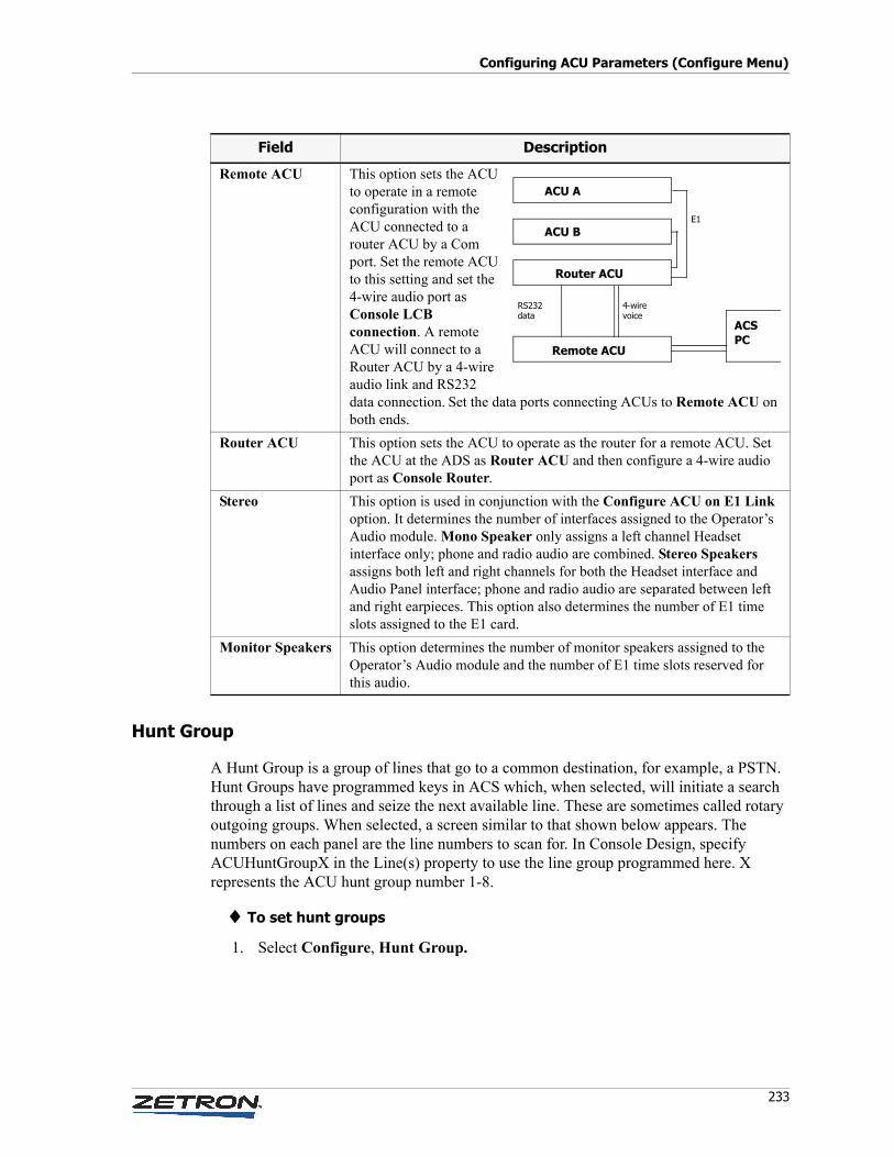
233
Configuring ACU Parameters (Configure Menu)
Hunt Group
A Hunt Group is a group of lines that go to a common destination, for example, a PSTN. Hunt Groups have programmed keys in ACS which, when selected, will initiate a search through a list of lines and seize the next available line. These are sometimes called rotary outgoing groups. When selected, a screen similar to that shown below appears. The numbers on each panel are the line numbers to scan for. In Console Design, specify ACUHuntGroupX in the Line(s) property to use the line group programmed here. X represents the ACU hunt group number 1-8.
♦ To set hunt groups
1. Select Configure, Hunt Group.
Remote ACU This option sets the ACU to operate in a remote configuration with the ACU connected to a router ACU by a Com port. Set the remote ACU to this setting and set the 4-wire audio port as Console LCB connection. A remote ACU will connect to a Router ACU by a 4-wire audio link and RS232 data connection. Set the data ports connecting ACUs to Remote ACU on both ends.
Router ACU This option sets the ACU to operate as the router for a remote ACU. Set the ACU at the ADS as Router ACU and then configure a 4-wire audio port as Console Router.
Stereo This option is used in conjunction with the Configure ACU on E1 Link option. It determines the number of interfaces assigned to the Operator’s Audio module. Mono Speaker only assigns a left channel Headset interface only; phone and radio audio are combined. Stereo Speakers assigns both left and right channels for both the Headset interface and Audio Panel interface; phone and radio audio are separated between left and right earpieces. This option also determines the number of E1 time slots assigned to the E1 card.
Monitor Speakers This option determines the number of monitor speakers assigned to the Operator’s Audio module and the number of E1 time slots reserved for this audio.
Field Description
ACU A
ACU B
Router ACU
Remote ACU
ACSPC
RS232data
4-wirevoice
E1
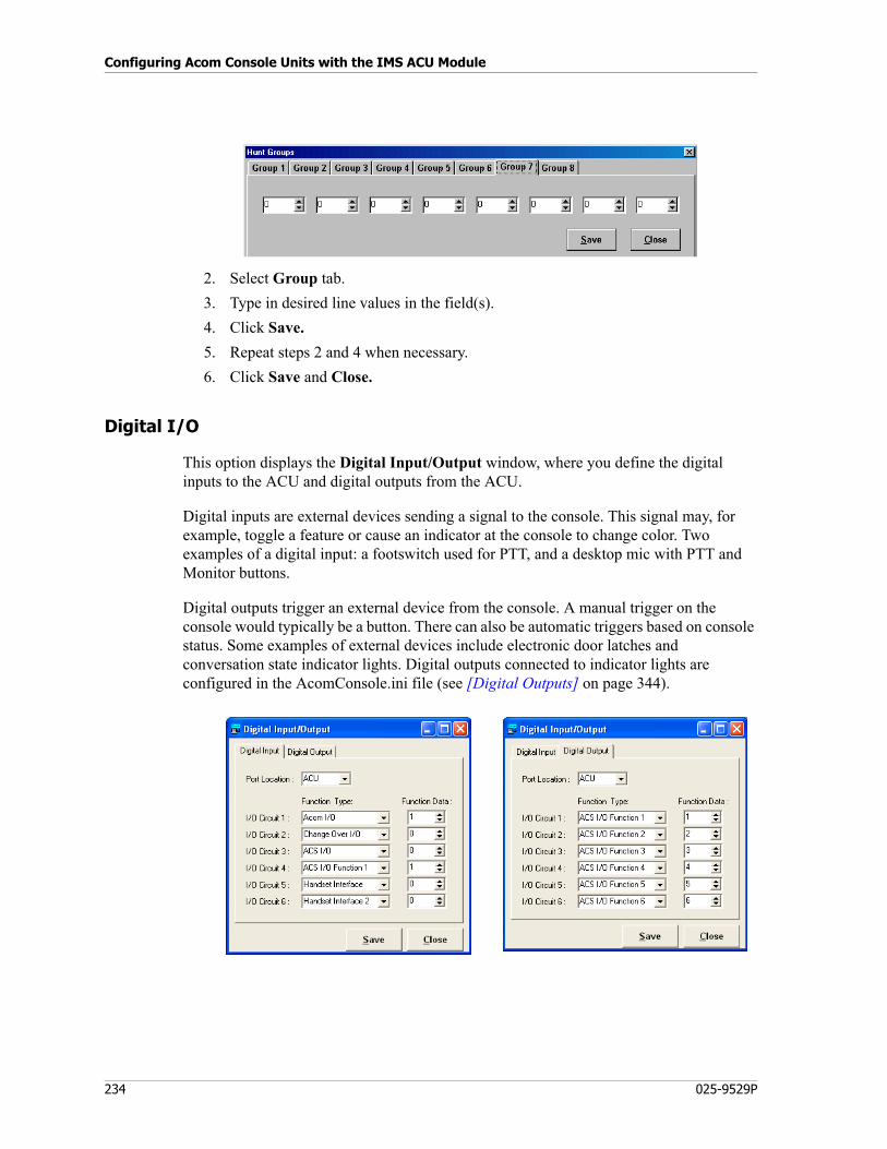
Configuring Acom Console Units with the IMS ACU Module
234 025-9529P
2. Select Group tab.
3. Type in desired line values in the field(s).
4. Click Save.
5. Repeat steps 2 and 4 when necessary.
6. Click Save and Close.
Digital I/O
This option displays the Digital Input/Output window, where you define the digital inputs to the ACU and digital outputs from the ACU.
Digital inputs are external devices sending a signal to the console. This signal may, for example, toggle a feature or cause an indicator at the console to change color. Two examples of a digital input: a footswitch used for PTT, and a desktop mic with PTT and Monitor buttons.
Digital outputs trigger an external device from the console. A manual trigger on the console would typically be a button. There can also be automatic triggers based on console status. Some examples of external devices include electronic door latches and conversation state indicator lights. Digital outputs connected to indicator lights are configured in the AcomConsole.ini file (see [Digital Outputs] on page 344).
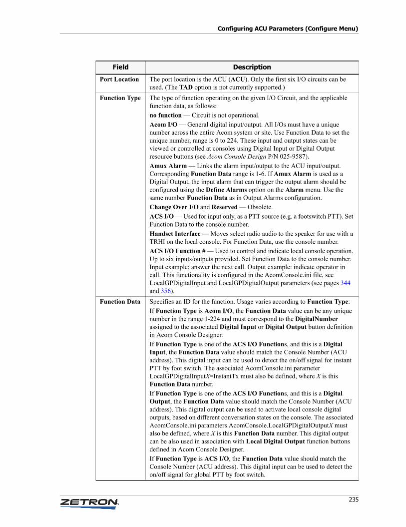
235
Configuring ACU Parameters (Configure Menu)
Field Description
Port Location The port location is the ACU (ACU). Only the first six I/O circuits can be used. (The TAD option is not currently supported.)
Function Type The type of function operating on the given I/O Circuit, and the applicable function data, as follows:
no function — Circuit is not operational.
Acom I/O — General digital input/output. All I/Os must have a unique number across the entire Acom system or site. Use Function Data to set the unique number, range is 0 to 224. These input and output states can be viewed or controlled at consoles using Digital Input or Digital Output resource buttons (see Acom Console Design P/N 025-9587).
Amux Alarm — Links the alarm input/output to the ACU input/output. Corresponding Function Data range is 1-6. If Amux Alarm is used as a Digital Output, the input alarm that can trigger the output alarm should be configured using the Define Alarms option on the Alarm menu. Use the same number Function Data as in Output Alarms configuration.
Change Over I/O and Reserved — Obsolete.
ACS I/O — Used for input only, as a PTT source (e.g. a footswitch PTT). Set Function Data to the console number.
Handset Interface — Moves select radio audio to the speaker for use with a TRHI on the local console. For Function Data, use the console number.
ACS I/O Function # — Used to control and indicate local console operation. Up to six inputs/outputs provided. Set Function Data to the console number. Input example: answer the next call. Output example: indicate operator in call. This functionality is configured in the AcomConsole.ini file, see LocalGPDigitalInput and LocalGPDigitalOutput parameters (see pages 344 and 356).
Function Data Specifies an ID for the function. Usage varies according to Function Type:
If Function Type is Acom I/O, the Function Data value can be any unique number in the range 1-224 and must correspond to the DigitalNumber assigned to the associated Digital Input or Digital Output button definition in Acom Console Designer.
If Function Type is one of the ACS I/O Functions, and this is a Digital Input, the Function Data value should match the Console Number (ACU address). This digital input can be used to detect the on/off signal for instant PTT by foot switch. The associated AcomConsole.ini parameter LocalGPDigitalInputX=InstantTx must also be defined, where X is this Function Data number.
If Function Type is one of the ACS I/O Functions, and this is a Digital Output, the Function Data value should match the Console Number (ACU address). This digital output can be used to activate local console digital outputs, based on different conversation states on the console. The associated AcomConsole.ini parameters AcomConsole.LocalGPDigitalOutputX must also be defined, where X is this Function Data number. This digital output can be also used in association with Local Digital Output function buttons defined in Acom Console Designer.
If Function Type is ACS I/O, the Function Data value should match the Console Number (ACU address). This digital input can be used to detect the on/off signal for global PTT by foot switch.
Configuring Acom Console Units with the IMS ACU Module
236 025-9529P
♦ To configure Digital I/Os (in general)
1. From the IMS ACU Configure menu, select Digital IO.
2. Select the Digital Input or Digital Output tab.
3. Select ACU from the Port Location drop-down list (default).
4. For the I/O Circuit #, select the appropriate function from the Function Type drop-down list.
5. In the Function Data field, enter a number to identify the function.
6. Click Save and Close.
7. For details on connecting a device to a digital input, contact Zetron Technical Support.
♦ To configure Console Conversation State lights
1. From the IMS ACU Configure menu, select Digital IO.
2. On the Digital Output tab, set the Function Type for I/O Circuit 1 to ACS I/O Function 1, and set its Function Data field to the console number.
3. In the AcomConsole.ini file, define the behavior of ACS output 1 to configure the behavior of the light. See LocalGPDigitalOutput#=ConvStateIndication&… on page 344.
♦ To configure a remote Answer Next device
This feature enables a console operator to execute the Answer Next function by way of some external device (for example, a button on a wireless headset, or a foot switch) connected to a digital input. This example uses digital input 1.
1. From the IMS ACU Configure menu, select Digital IO.
2. On the Digital Input tab, set the Function Type for I/O Circuit 1 to ACS I/O Function 1, and set its Function Data field to the console number.
3. In the AcomConsole.ini file, define the behavior of ACS Input 1 to configure the behavior of the input by setting LocalGPDigitalInput1=AnswerNext (see “Answer Next” in LocalGPDigitalInputX=Function on page 356).
♦ To configure a foot switch for Instant TX
Use the same procedure as To configure a remote Answer Next device on page 236, except set LocalGPDigitalInput1=InstantTx.
Alert Tones
The ACS Alert tone can be assigned from the Alert Tone Configuration window.
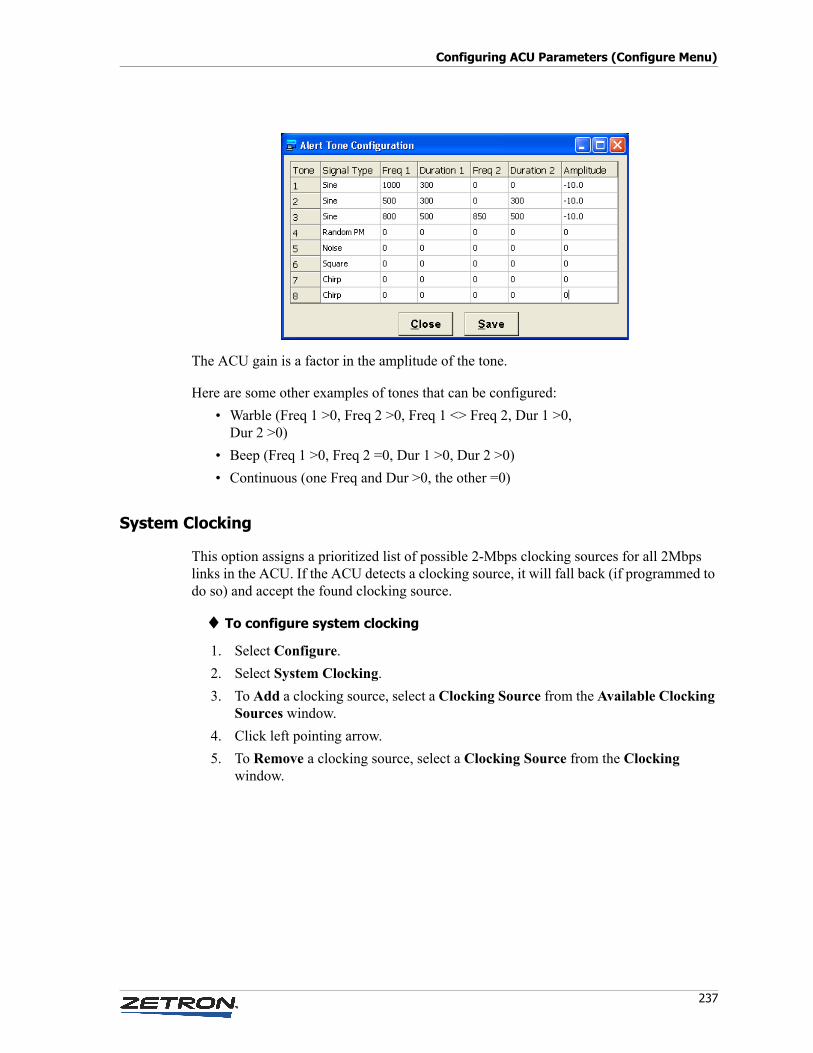
237
Configuring ACU Parameters (Configure Menu)
The ACU gain is a factor in the amplitude of the tone.
Here are some other examples of tones that can be configured:
• Warble (Freq 1 >0, Freq 2 >0, Freq 1 <> Freq 2, Dur 1 >0, Dur 2 >0)
• Beep (Freq 1 >0, Freq 2 =0, Dur 1 >0, Dur 2 >0)
• Continuous (one Freq and Dur >0, the other =0)
System Clocking
This option assigns a prioritized list of possible 2-Mbps clocking sources for all 2Mbps links in the ACU. If the ACU detects a clocking source, it will fall back (if programmed to do so) and accept the found clocking source.
♦ To configure system clocking
1. Select Configure.
2. Select System Clocking.
3. To Add a clocking source, select a Clocking Source from the Available Clocking Sources window.
4. Click left pointing arrow.
5. To Remove a clocking source, select a Clocking Source from the Clocking window.
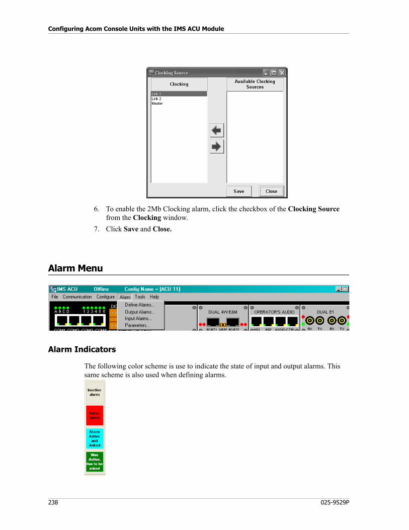
Configuring Acom Console Units with the IMS ACU Module
238 025-9529P
6. To enable the 2Mb Clocking alarm, click the checkbox of the Clocking Source from the Clocking window.
7. Click Save and Close.
Alarm Menu
Alarm Indicators
The following color scheme is use to indicate the state of input and output alarms. This same scheme is also used when defining alarms.
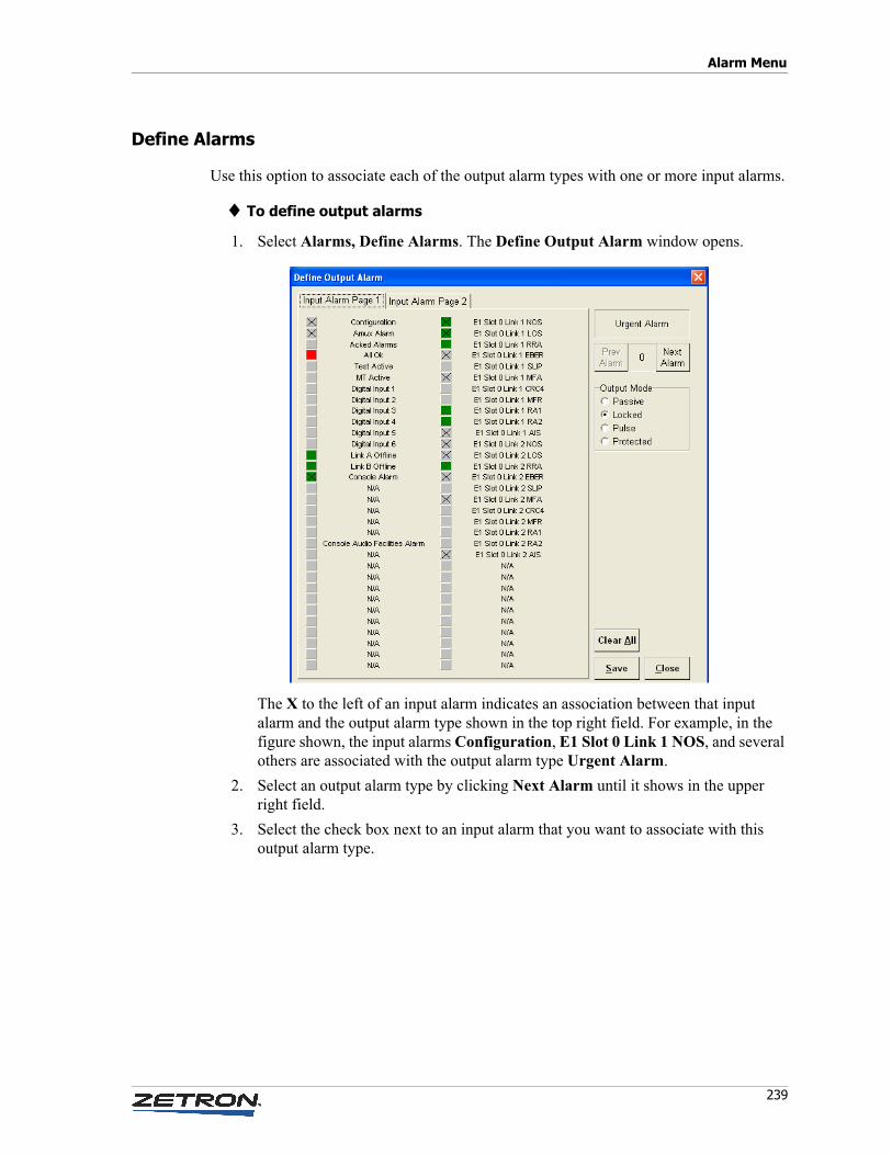
239
Alarm Menu
Define Alarms
Use this option to associate each of the output alarm types with one or more input alarms.
♦ To define output alarms
1. Select Alarms, Define Alarms. The Define Output Alarm window opens.
The X to the left of an input alarm indicates an association between that input alarm and the output alarm type shown in the top right field. For example, in the figure shown, the input alarms Configuration, E1 Slot 0 Link 1 NOS, and several others are associated with the output alarm type Urgent Alarm.
2. Select an output alarm type by clicking Next Alarm until it shows in the upper right field.
3. Select the check box next to an input alarm that you want to associate with this output alarm type.
Configuring Acom Console Units with the IMS ACU Module
240 025-9529P
4. Select the Output Mode for this alarm, according to the following table:
5. Repeat steps 3-4 for all of the other input alarms that you want to associate with this output alarm type. Note that there are two tabs of input alarms.
6. Return to step 2 and choose the next output alarm type. Repeat this process until all output alarm types have the appropriate input alarms and output mode associated with them.
7. Click Save and Close.
Output Alarms
Use this option to view the current output alarms. This option is not available when the system is offline.
♦ To view output alarms
1. Select Alarm, Output Alarms. The Output Alarms window opens.
Mode Description
Passive An output is active if: ANY of its inputs are "Active".
An output is inactive if: ALL of its inputs are either "Inactive", "Was Active, Has to be Acked", or "Active and Acked".
Pulse An output is active if: ANY of its inputs are "Active".
An output is inactive if: ALL of its inputs are either "Inactive", "Was Active, Has to be Acked", or "Active and Acked".
“Physical” digital output is pulsed.
Locked An output is active if: ANY of its inputs are either "Active", "Was Active, Has to be Acked", or "Active and Acked".
An output is inactive if: ALL of its inputs are "Inactive".
Protected An output is active if: ANY of its inputs are either "Active", or "Active and Acked".
An output is inactive if: ALL of its inputs are "Inactive" or "Was Active, Has to be Acked".

241
Alarm Menu
The alarms shown are associated with one or more input alarms.
2. If you need to adjust the definition of one of these alarms, you can click the marker, and the Define Output Alarm window will open. See Define Alarms on page 239.
3. Click Close.
Input Alarms
Use this option to view and acknowledge input alarms. This option is not available when the system is offline.
♦ To view and acknowledge input alarms
1. Select Alarm, Input Alarms. The Input Alarms window opens.
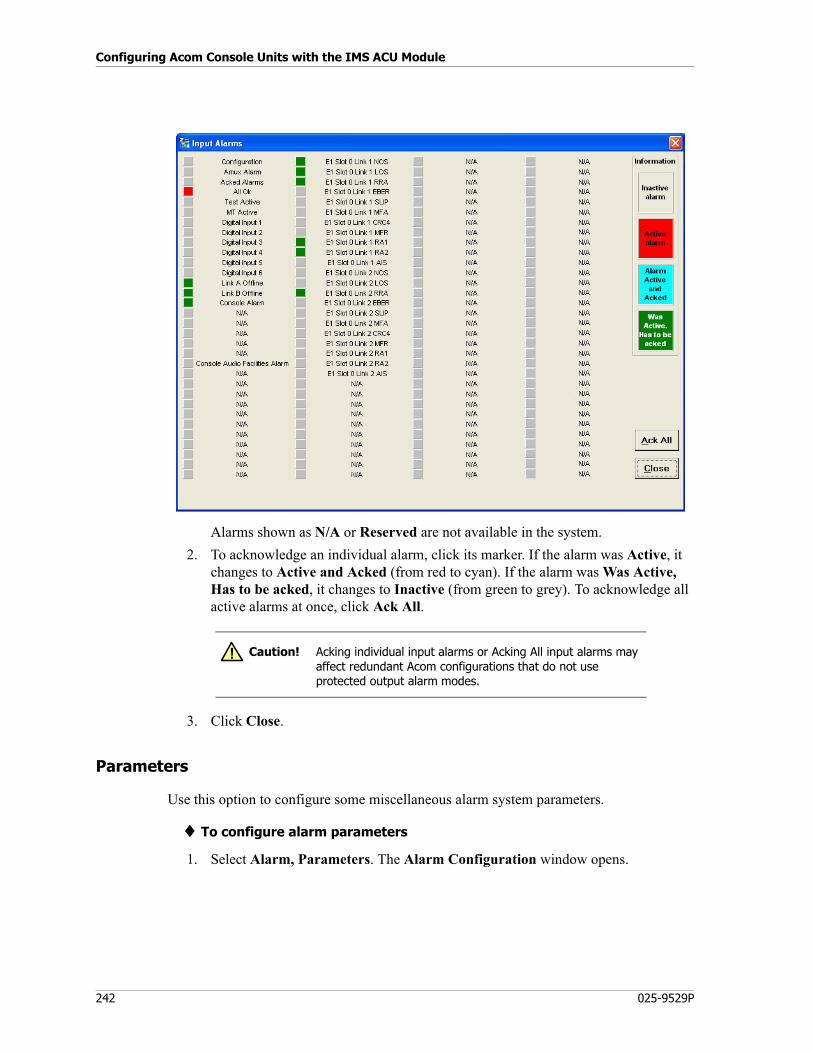
Configuring Acom Console Units with the IMS ACU Module
242 025-9529P
Alarms shown as N/A or Reserved are not available in the system.
2. To acknowledge an individual alarm, click its marker. If the alarm was Active, it changes to Active and Acked (from red to cyan). If the alarm was Was Active, Has to be acked, it changes to Inactive (from green to grey). To acknowledge all active alarms at once, click Ack All.
3. Click Close.
Parameters
Use this option to configure some miscellaneous alarm system parameters.
♦ To configure alarm parameters
1. Select Alarm, Parameters. The Alarm Configuration window opens.
Caution! Acking individual input alarms or Acking All input alarms may affect redundant Acom configurations that do not use protected output alarm modes.
!
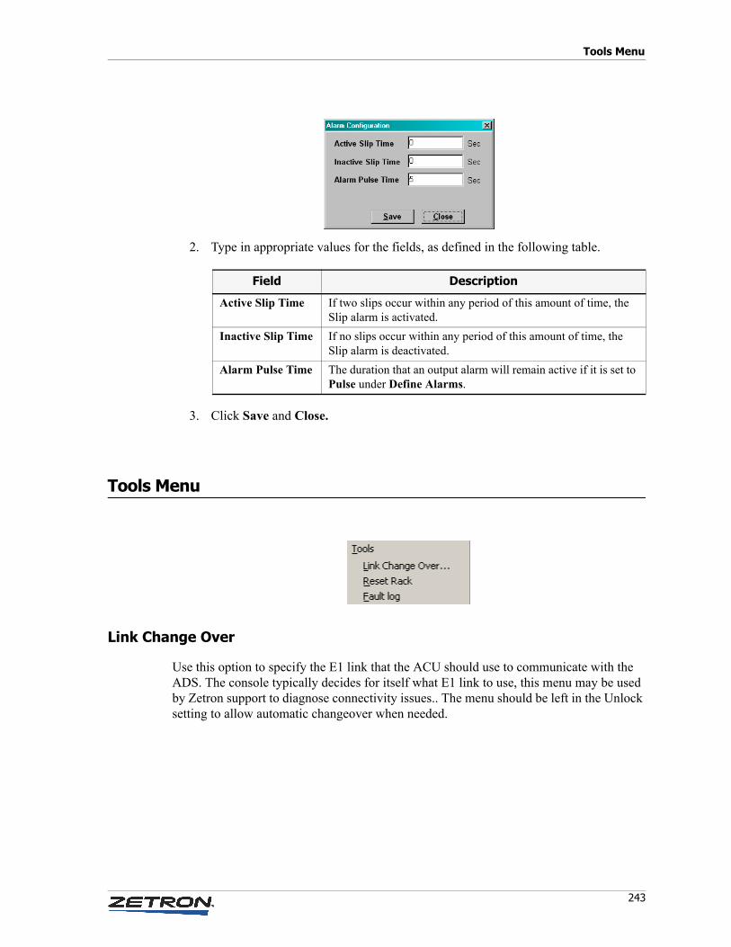
243
Tools Menu
2. Type in appropriate values for the fields, as defined in the following table.
3. Click Save and Close.
Tools Menu
Link Change Over
Use this option to specify the E1 link that the ACU should use to communicate with the ADS. The console typically decides for itself what E1 link to use, this menu may be used by Zetron support to diagnose connectivity issues.. The menu should be left in the Unlock setting to allow automatic changeover when needed.
Field Description
Active Slip Time If two slips occur within any period of this amount of time, the Slip alarm is activated.
Inactive Slip Time If no slips occur within any period of this amount of time, the Slip alarm is deactivated.
Alarm Pulse Time The duration that an output alarm will remain active if it is set to Pulse under Define Alarms.
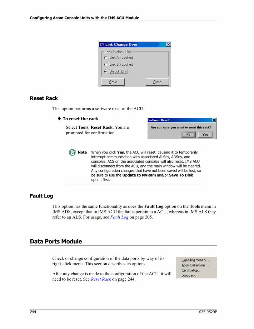
Configuring Acom Console Units with the IMS ACU Module
244 025-9529P
Reset Rack
This option performs a software reset of the ACU.
♦ To reset the rack
Select Tools, Reset Rack. You are prompted for confirmation.
Fault Log
This option has the same functionality as does the Fault Log option on the Tools menu in IMS ADS, except that in IMS ACU the faults pertain to a ACU, whereas in IMS ALS they refer to an ALS. For usage, see Fault Log on page 205.
Data Ports Module
Check or change configuration of the data ports by way of its right-click menu. This section describes its options.
After any change is made to the configuration of the ACU, it will need to be reset. See Reset Rack on page 244.
Note When you click Yes, the ACU will reset, causing it to temporarily interrupt communication with associated ALSes, ADSes, and consoles. ACS on the associated consoles will also reset. IMS ACU will disconnect from the ACU, and the main window will be cleared. Any configuration changes that have not been saved will be lost, so be sure to use the Update to NVRam and/or Save To Disk option first.
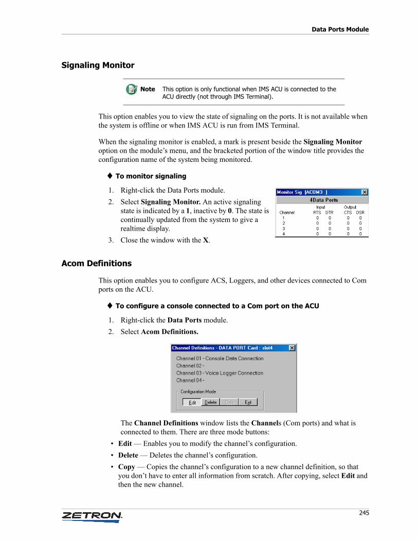
245
Data Ports Module
Signaling Monitor
This option enables you to view the state of signaling on the ports. It is not available when the system is offline or when IMS ACU is run from IMS Terminal.
When the signaling monitor is enabled, a mark is present beside the Signaling Monitor option on the module’s menu, and the bracketed portion of the window title provides the configuration name of the system being monitored.
♦ To monitor signaling
1. Right-click the Data Ports module.
2. Select Signaling Monitor. An active signaling state is indicated by a 1, inactive by 0. The state is continually updated from the system to give a realtime display.
3. Close the window with the X.
Acom Definitions
This option enables you to configure ACS, Loggers, and other devices connected to Com ports on the ACU.
♦ To configure a console connected to a Com port on the ACU
1. Right-click the Data Ports module.
2. Select Acom Definitions.
The Channel Definitions window lists the Channels (Com ports) and what is connected to them. There are three mode buttons:
• Edit — Enables you to modify the channel’s configuration.
• Delete — Deletes the channel’s configuration.
• Copy — Copies the channel’s configuration to a new channel definition, so that you don’t have to enter all information from scratch. After copying, select Edit and then the new channel.
Note This option is only functional when IMS ACU is connected to the ACU directly (not through IMS Terminal).
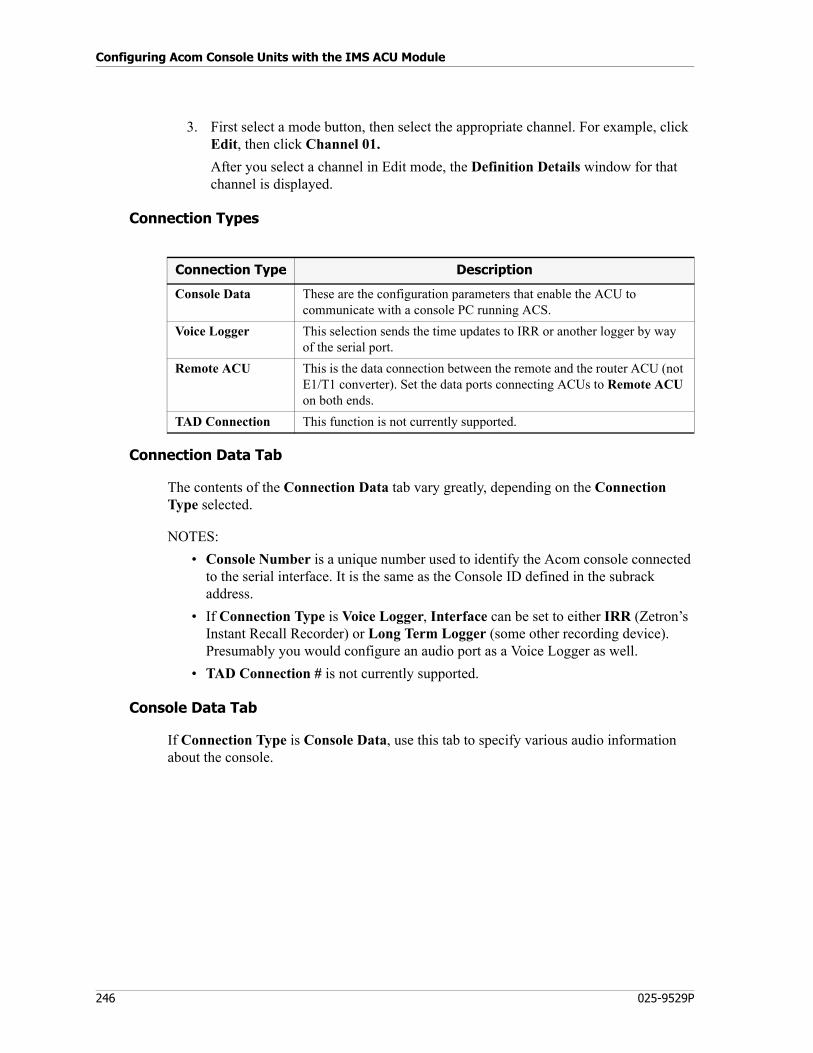
Configuring Acom Console Units with the IMS ACU Module
246 025-9529P
3. First select a mode button, then select the appropriate channel. For example, click Edit, then click Channel 01.
After you select a channel in Edit mode, the Definition Details window for that channel is displayed.
Connection Types
Connection Data Tab
The contents of the Connection Data tab vary greatly, depending on the Connection Type selected.
NOTES:
• Console Number is a unique number used to identify the Acom console connected to the serial interface. It is the same as the Console ID defined in the subrack address.
• If Connection Type is Voice Logger, Interface can be set to either IRR (Zetron’s Instant Recall Recorder) or Long Term Logger (some other recording device). Presumably you would configure an audio port as a Voice Logger as well.
• TAD Connection # is not currently supported.
Console Data Tab
If Connection Type is Console Data, use this tab to specify various audio information about the console.
Connection Type Description
Console Data These are the configuration parameters that enable the ACU to communicate with a console PC running ACS.
Voice Logger This selection sends the time updates to IRR or another logger by way of the serial port.
Remote ACU This is the data connection between the remote and the router ACU (not E1/T1 converter). Set the data ports connecting ACUs to Remote ACU on both ends.
TAD Connection This function is not currently supported.
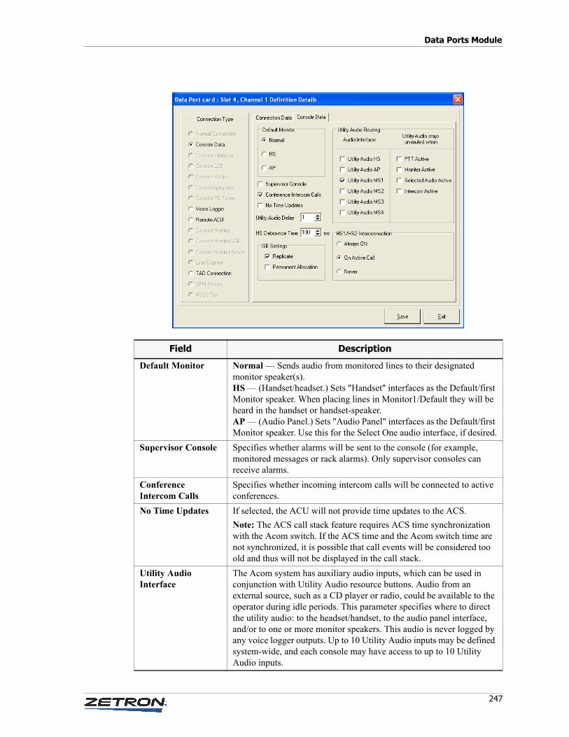
247
Data Ports Module
Field Description
Default Monitor Normal — Sends audio from monitored lines to their designated monitor speaker(s).HS — (Handset/headset.) Sets "Handset" interfaces as the Default/first Monitor speaker. When placing lines in Monitor1/Default they will be heard in the handset or handset-speaker.AP — (Audio Panel.) Sets "Audio Panel" interfaces as the Default/first Monitor speaker. Use this for the Select One audio interface, if desired.
Supervisor Console Specifies whether alarms will be sent to the console (for example, monitored messages or rack alarms). Only supervisor consoles can receive alarms.
ConferenceIntercom Calls
Specifies whether incoming intercom calls will be connected to active conferences.
No Time Updates If selected, the ACU will not provide time updates to the ACS.
Note: The ACS call stack feature requires ACS time synchronization with the Acom switch. If the ACS time and the Acom switch time are not synchronized, it is possible that call events will be considered too old and thus will not be displayed in the call stack.
Utility Audio Interface
The Acom system has auxiliary audio inputs, which can be used in conjunction with Utility Audio resource buttons. Audio from an external source, such as a CD player or radio, could be available to the operator during idle periods. This parameter specifies where to direct the utility audio: to the headset/handset, to the audio panel interface, and/or to one or more monitor speakers. This audio is never logged by any voice logger outputs. Up to 10 Utility Audio inputs may be defined system-wide, and each console may have access to up to 10 Utility Audio inputs.
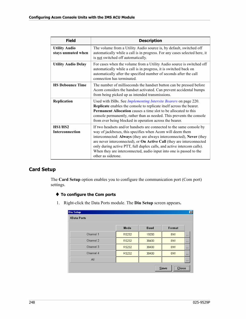
Configuring Acom Console Units with the IMS ACU Module
248 025-9529P
Card Setup
The Card Setup option enables you to configure the communication port (Com port) settings.
♦ To configure the Com ports
1. Right-click the Data Ports module. The Diu Setup screen appears.
Utility Audio stays unmuted when
The volume from a Utility Audio source is, by default, switched off automatically while a call is in progress. For any cases selected here, it is not switched off automatically.
Utility Audio Delay For cases when the volume from a Utility Audio source is switched off automatically while a call is in progress, it is switched back on automatically after the specified number of seconds after the call connection has terminated.
HS Debounce Time The number of milliseconds the handset button can be pressed before Acom considers the handset activated. Can prevent accidental bumps from being picked up as intended transmissions.
Replication Used with ISBs. See Implementing Intersite Bearers on page 220. Replicate enables the console to replicate itself across the bearer. Permanent Allocation causes a time slot to be allocated to this console permanently, rather than as needed. This prevents the console from ever being blocked in operation across the bearer.
HS1/HS2 Interconnection
If two headsets and/or handsets are connected to the same console by way of jackboxes, this specifies when Acom will deem them interconnected: Always (they are always interconnected), Never (they are never interconnected), or On Active Call (they are interconnected only during active PTT, full duplex calls, and active intercom calls). When they are interconnected, audio input into one is passed to the other as sidetone.
Field Description
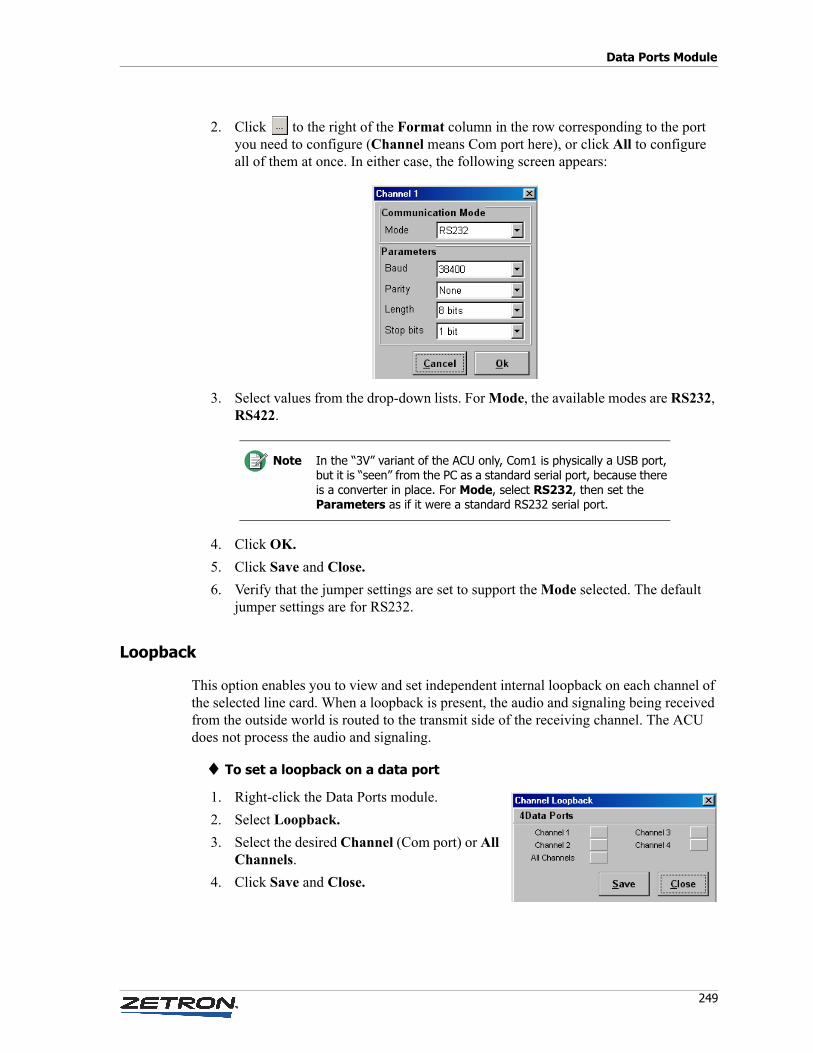
249
Data Ports Module
2. Click to the right of the Format column in the row corresponding to the port you need to configure (Channel means Com port here), or click All to configure all of them at once. In either case, the following screen appears:
3. Select values from the drop-down lists. For Mode, the available modes are RS232, RS422.
4. Click OK.
5. Click Save and Close.
6. Verify that the jumper settings are set to support the Mode selected. The default jumper settings are for RS232.
Loopback
This option enables you to view and set independent internal loopback on each channel of the selected line card. When a loopback is present, the audio and signaling being received from the outside world is routed to the transmit side of the receiving channel. The ACU does not process the audio and signaling.
♦ To set a loopback on a data port
1. Right-click the Data Ports module.
2. Select Loopback.
3. Select the desired Channel (Com port) or All Channels.
4. Click Save and Close.
Note In the “3V” variant of the ACU only, Com1 is physically a USB port, but it is “seen” from the PC as a standard serial port, because there is a converter in place. For Mode, select RS232, then set the Parameters as if it were a standard RS232 serial port.
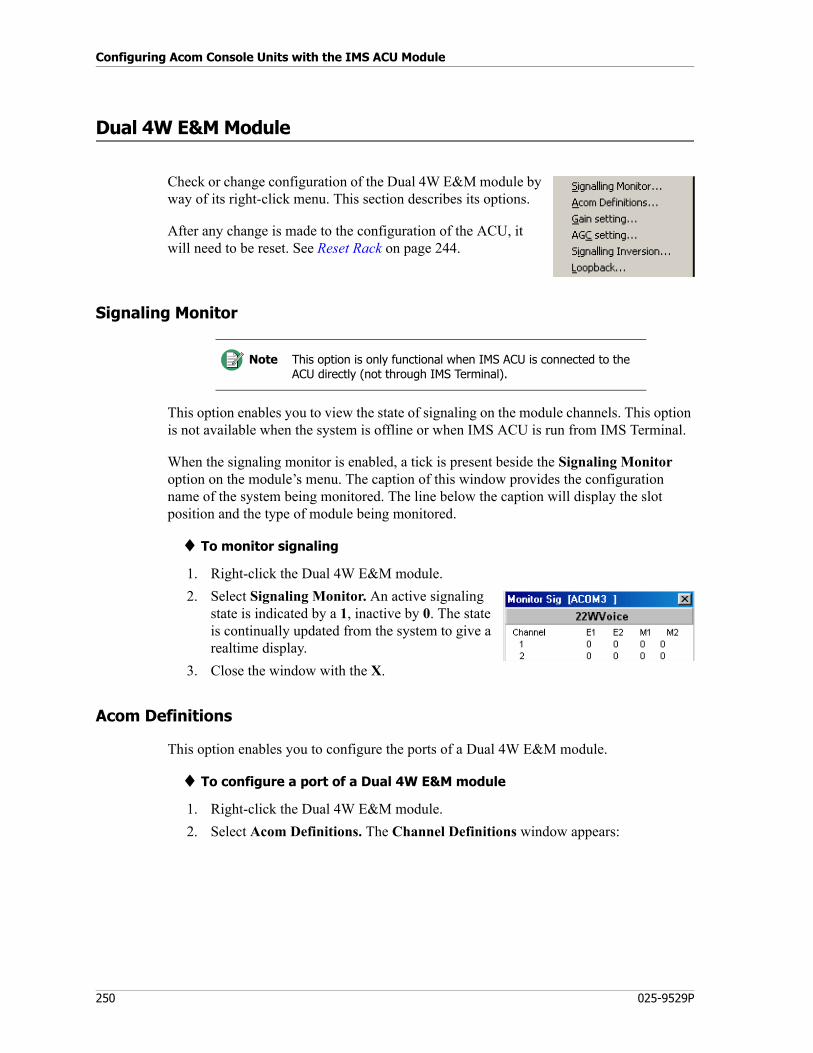
Configuring Acom Console Units with the IMS ACU Module
250 025-9529P
Dual 4W E&M Module
Check or change configuration of the Dual 4W E&M module by way of its right-click menu. This section describes its options.
After any change is made to the configuration of the ACU, it will need to be reset. See Reset Rack on page 244.
Signaling Monitor
This option enables you to view the state of signaling on the module channels. This option is not available when the system is offline or when IMS ACU is run from IMS Terminal.
When the signaling monitor is enabled, a tick is present beside the Signaling Monitor option on the module’s menu. The caption of this window provides the configuration name of the system being monitored. The line below the caption will display the slot position and the type of module being monitored.
♦ To monitor signaling
1. Right-click the Dual 4W E&M module.
2. Select Signaling Monitor. An active signaling state is indicated by a 1, inactive by 0. The state is continually updated from the system to give a realtime display.
3. Close the window with the X.
Acom Definitions
This option enables you to configure the ports of a Dual 4W E&M module.
♦ To configure a port of a Dual 4W E&M module
1. Right-click the Dual 4W E&M module.
2. Select Acom Definitions. The Channel Definitions window appears:
Note This option is only functional when IMS ACU is connected to the ACU directly (not through IMS Terminal).
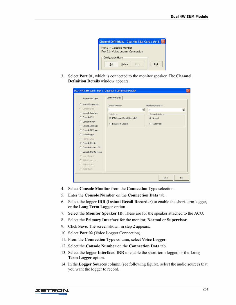
251
Dual 4W E&M Module
3. Select Port 01, which is connected to the monitor speaker. The Channel Definition Details window appears.
4. Select Console Monitor from the Connection Type selection.
5. Enter the Console Number on the Connection Data tab.
6. Select the logger IRR (Instant Recall Recorder) to enable the short-term logger, or the Long Term Logger option.
7. Select the Monitor Speaker ID. These are for the speaker attached to the ACU.
8. Select the Primary Interface for the monitor, Normal or Supervisor.
9. Click Save. The screen shown in step 2 appears.
10. Select Port 02 (Voice Logger Connection).
11. From the Connection Type column, select Voice Logger.
12. Select the Console Number on the Connection Data tab.
13. Select the logger Interface: IRR to enable the short-term logger, or the Long Term Logger option.
14. In the Logger Sources column (see following figure), select the audio sources that you want the logger to record.
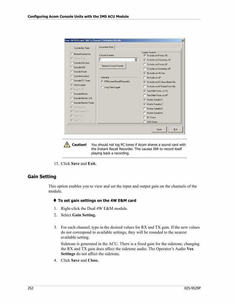
Configuring Acom Console Units with the IMS ACU Module
252 025-9529P
15. Click Save and Exit.
Gain Setting
This option enables you to view and set the input and output gain on the channels of the module.
♦ To set gain settings on the 4W E&M card
1. Right-click the Dual 4W E&M module.
2. Select Gain Setting.
3. For each channel, type in the desired values for RX and TX gain. If the new values do not correspond to available settings, they will be rounded to the nearest available setting.
Sidetone is generated in the ACU. There is a fixed gain for the sidetone; changing the RX and TX gain does affect the sidetone audio. The Operator’s Audio Vox Settings do not affect the sidetone.
4. Click Save and Close.
Caution! You should not log PC tones if Acom shares a sound card with the Instant Recall Recorder. This causes IRR to record itself playing back a recording.
!
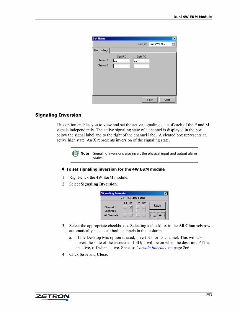
253
Dual 4W E&M Module
Signaling Inversion
This option enables you to view and set the active signaling state of each of the E and M signals independently. The active signaling state of a channel is displayed in the box below the signal label and to the right of the channel label. A cleared box represents an active high state. An X represents inversion of the signaling state.
♦ To set signaling inversion for the 4W E&M module
1. Right-click the 4W E&M module.
2. Select Signaling Inversion.
3. Select the appropriate checkboxes. Selecting a checkbox in the All Channels row automatically selects all both channels in that column.
a. If the Desktop Mic option is used, invert E1 for its channel. This will also invert the state of the associated LED; it will be on when the desk mic PTT is inactive, off when active. See also Console Interface on page 266.
4. Click Save and Close.
Note Signaling inversions also invert the physical input and output alarm states.
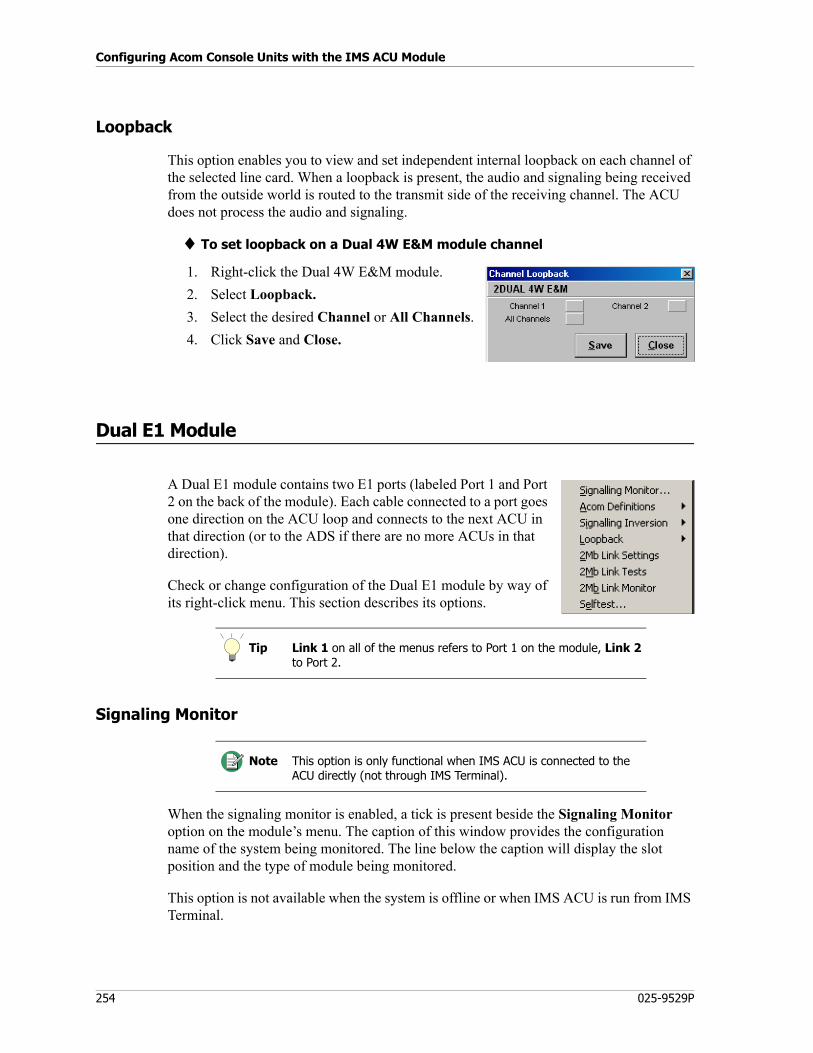
Configuring Acom Console Units with the IMS ACU Module
254 025-9529P
Loopback
This option enables you to view and set independent internal loopback on each channel of the selected line card. When a loopback is present, the audio and signaling being received from the outside world is routed to the transmit side of the receiving channel. The ACU does not process the audio and signaling.
♦ To set loopback on a Dual 4W E&M module channel
1. Right-click the Dual 4W E&M module.
2. Select Loopback.
3. Select the desired Channel or All Channels.
4. Click Save and Close.
Dual E1 Module
A Dual E1 module contains two E1 ports (labeled Port 1 and Port 2 on the back of the module). Each cable connected to a port goes one direction on the ACU loop and connects to the next ACU in that direction (or to the ADS if there are no more ACUs in that direction).
Check or change configuration of the Dual E1 module by way of its right-click menu. This section describes its options.
Signaling Monitor
When the signaling monitor is enabled, a tick is present beside the Signaling Monitor option on the module’s menu. The caption of this window provides the configuration name of the system being monitored. The line below the caption will display the slot position and the type of module being monitored.
This option is not available when the system is offline or when IMS ACU is run from IMS Terminal.
Tip Link 1 on all of the menus refers to Port 1 on the module, Link 2 to Port 2.
Note This option is only functional when IMS ACU is connected to the ACU directly (not through IMS Terminal).
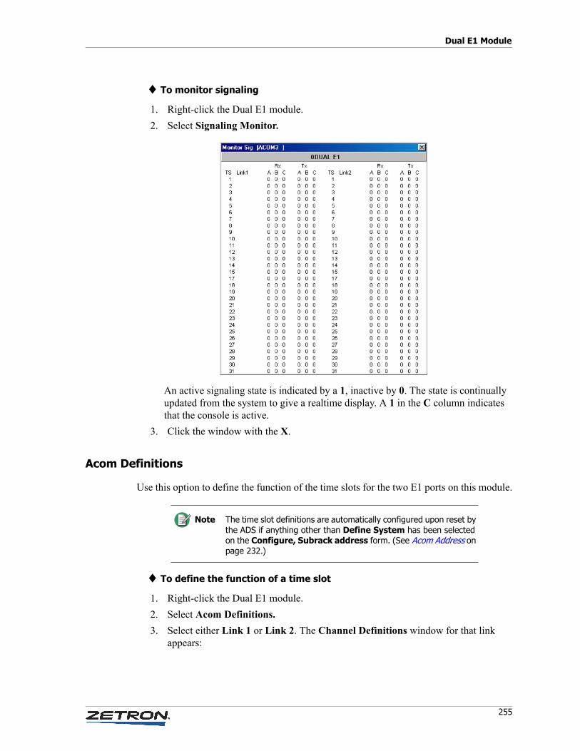
255
Dual E1 Module
♦ To monitor signaling
1. Right-click the Dual E1 module.
2. Select Signaling Monitor.
An active signaling state is indicated by a 1, inactive by 0. The state is continually updated from the system to give a realtime display. A 1 in the C column indicates that the console is active.
3. Click the window with the X.
Acom Definitions
Use this option to define the function of the time slots for the two E1 ports on this module.
♦ To define the function of a time slot
1. Right-click the Dual E1 module.
2. Select Acom Definitions.
3. Select either Link 1 or Link 2. The Channel Definitions window for that link appears:
Note The time slot definitions are automatically configured upon reset by the ADS if anything other than Define System has been selected on the Configure, Subrack address form. (See Acom Address on page 232.)
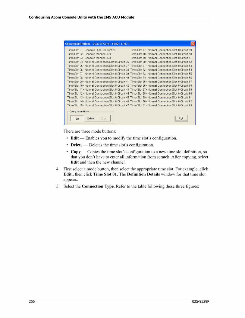
Configuring Acom Console Units with the IMS ACU Module
256 025-9529P
There are three mode buttons:
• Edit — Enables you to modify the time slot’s configuration.
• Delete — Deletes the time slot’s configuration.
• Copy — Copies the time slot’s configuration to a new time slot definition, so that you don’t have to enter all information from scratch. After copying, select Edit and then the new channel.
4. First select a mode button, then select the appropriate time slot. For example, click Edit., then click Time Slot 01. The Definition Details window for that time slot appears.
5. Select the Connection Type. Refer to the table following these three figures:
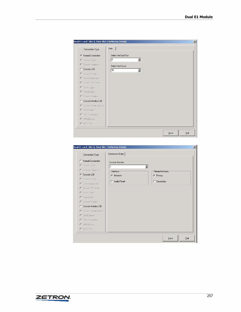
257
Dual E1 Module
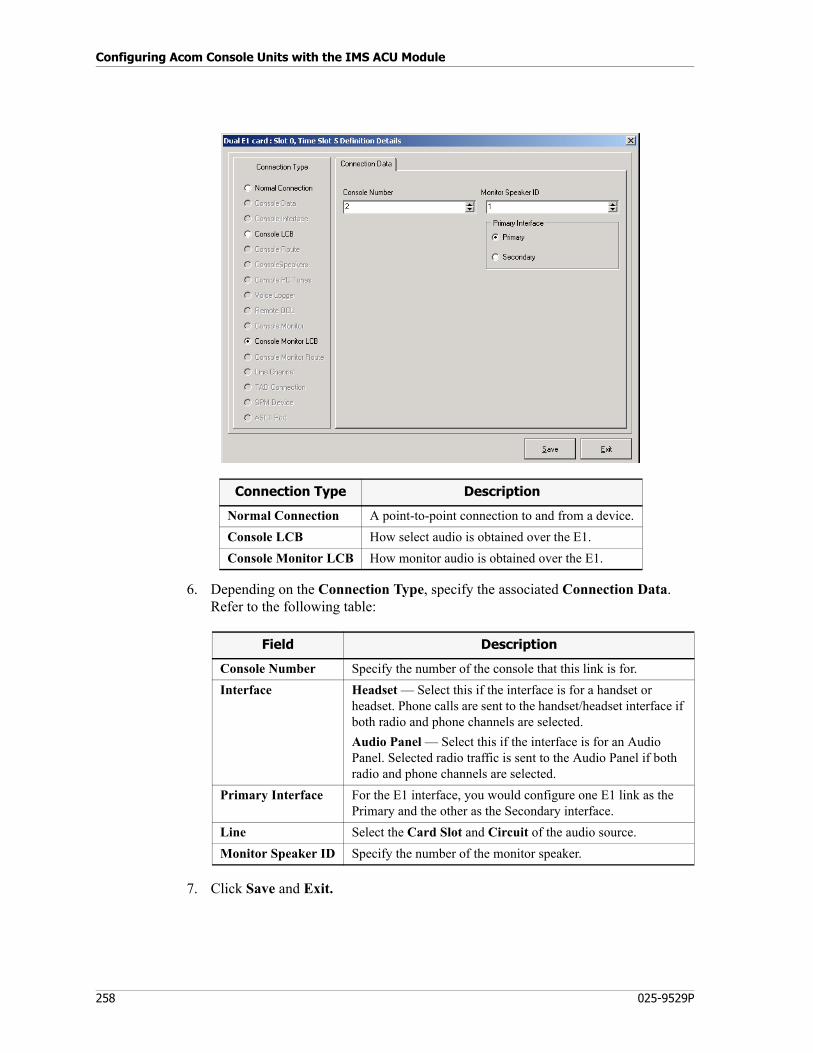
Configuring Acom Console Units with the IMS ACU Module
258 025-9529P
6. Depending on the Connection Type, specify the associated Connection Data. Refer to the following table:
7. Click Save and Exit.
Connection Type Description
Normal Connection A point-to-point connection to and from a device.
Console LCB How select audio is obtained over the E1.
Console Monitor LCB How monitor audio is obtained over the E1.
Field Description
Console Number Specify the number of the console that this link is for.
Interface Headset — Select this if the interface is for a handset or headset. Phone calls are sent to the handset/headset interface if both radio and phone channels are selected.
Audio Panel — Select this if the interface is for an Audio Panel. Selected radio traffic is sent to the Audio Panel if both radio and phone channels are selected.
Primary Interface For the E1 interface, you would configure one E1 link as the Primary and the other as the Secondary interface.
Line Select the Card Slot and Circuit of the audio source.
Monitor Speaker ID Specify the number of the monitor speaker.
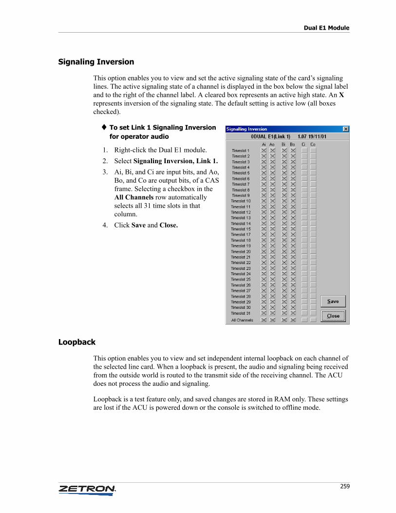
259
Dual E1 Module
Signaling Inversion
This option enables you to view and set the active signaling state of the card’s signaling lines. The active signaling state of a channel is displayed in the box below the signal label and to the right of the channel label. A cleared box represents an active high state. An X represents inversion of the signaling state. The default setting is active low (all boxes checked).
♦ To set Link 1 Signaling Inversion for operator audio
1. Right-click the Dual E1 module.
2. Select Signaling Inversion, Link 1.
3. Ai, Bi, and Ci are input bits, and Ao, Bo, and Co are output bits, of a CAS frame. Selecting a checkbox in the All Channels row automatically selects all 31 time slots in that column.
4. Click Save and Close.
Loopback
This option enables you to view and set independent internal loopback on each channel of the selected line card. When a loopback is present, the audio and signaling being received from the outside world is routed to the transmit side of the receiving channel. The ACU does not process the audio and signaling.
Loopback is a test feature only, and saved changes are stored in RAM only. These settings are lost if the ACU is powered down or the console is switched to offline mode.
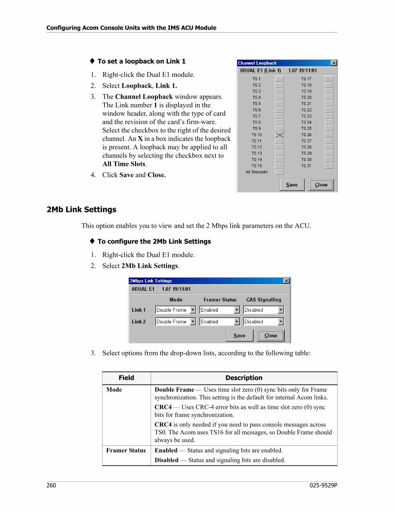
Configuring Acom Console Units with the IMS ACU Module
260 025-9529P
♦ To set a loopback on Link 1
1. Right-click the Dual E1 module.
2. Select Loopback, Link 1.
3. The Channel Loopback window appears. The Link number 1 is displayed in the window header, along with the type of card and the revision of the card’s firm-ware. Select the checkbox to the right of the desired channel. An X in a box indicates the loopback is present. A loopback may be applied to all channels by selecting the checkbox next to All Time Slots.
4. Click Save and Close.
2Mb Link Settings
This option enables you to view and set the 2 Mbps link parameters on the ACU.
♦ To configure the 2Mb Link Settings
1. Right-click the Dual E1 module.
2. Select 2Mb Link Settings.
3. Select options from the drop-down lists, according to the following table:
Field Description
Mode Double Frame — Uses time slot zero (0) sync bits only for Frame synchronization. This setting is the default for internal Acom links.
CRC4 — Uses CRC-4 error bits as well as time slot zero (0) sync bits for frame synchronization.
CRC4 is only needed if you need to pass console messages across TS0. The Acom uses TS16 for all messages, so Double Frame should always be used.
Framer Status Enabled — Status and signaling bits are enabled.
Disabled — Status and signaling bits are disabled.
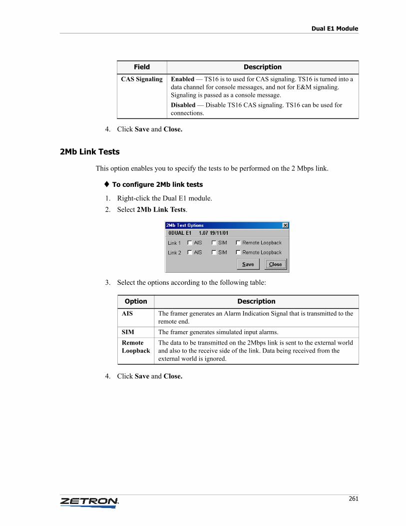
261
Dual E1 Module
4. Click Save and Close.
2Mb Link Tests
This option enables you to specify the tests to be performed on the 2 Mbps link.
♦ To configure 2Mb link tests
1. Right-click the Dual E1 module.
2. Select 2Mb Link Tests.
3. Select the options according to the following table:
4. Click Save and Close.
CAS Signaling Enabled — TS16 is to used for CAS signaling. TS16 is turned into a data channel for console messages, and not for E&M signaling. Signaling is passed as a console message.
Disabled — Disable TS16 CAS signaling. TS16 can be used for connections.
Field Description
Option Description
AIS The framer generates an Alarm Indication Signal that is transmitted to the remote end.
SIM The framer generates simulated input alarms.
RemoteLoopback
The data to be transmitted on the 2Mbps link is sent to the external world and also to the receive side of the link. Data being received from the external world is ignored.
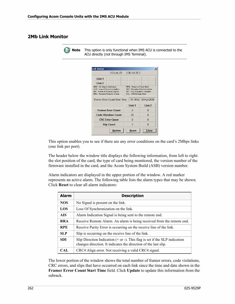
Configuring Acom Console Units with the IMS ACU Module
262 025-9529P
2Mb Link Monitor
This option enables you to see if there are any error conditions on the card’s 2Mbps links (one link per port).
The header below the window title displays the following information, from left to right: the slot position of the card, the type of card being monitored, the version number of the firmware installed in the card, and the Acom System Build (ASB) version number.
Alarm indicators are displayed in the upper portion of the window. A red marker represents an active alarm. The following table lists the alarm types that may be shown. Click Reset to clear all alarm indicators:
The lower portion of the window shows the total number of framer errors, code violations, CRC errors, and slips that have occurred on each link since the time and date shown in the Framer Error Count Start Time field. Click Update to update this information from the subrack.
Note This option is only functional when IMS ACU is connected to the ACU directly (not through IMS Terminal).
Alarm Description
NOS No Signal is present on the link.
LOS Loss Of Synchronization on the link.
AIS Alarm Indication Signal is being sent to the remote end.
RRA Receive Remote Alarm. An alarm is being received from the remote end.
RPE Receive Parity Error is occurring on the receive line of the link.
SLP Slip is occurring on the receive line of the link.
SDI Slip Direction Indication (+ or -). This flag is set if the SLP indication changes direction. It indicates the direction of the last slip.
CAL CRC4 Align error. Not receiving a valid CRC4 signal.
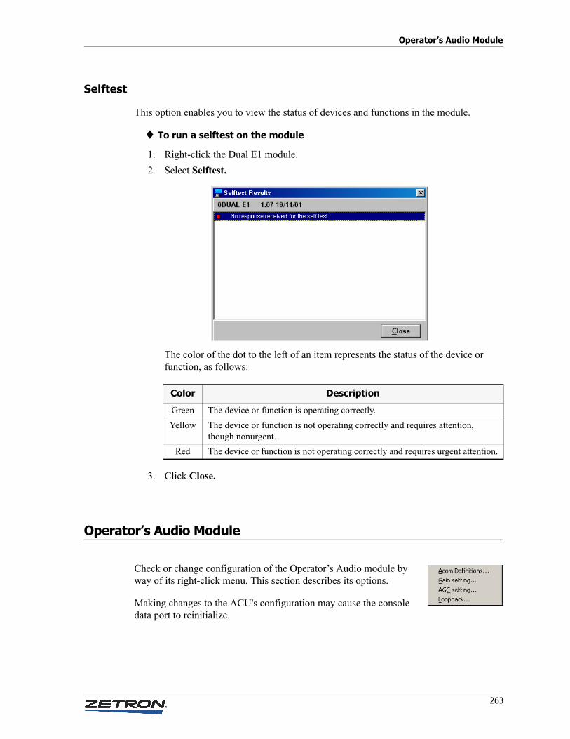
263
Operator’s Audio Module
Selftest
This option enables you to view the status of devices and functions in the module.
♦ To run a selftest on the module
1. Right-click the Dual E1 module.
2. Select Selftest.
The color of the dot to the left of an item represents the status of the device or function, as follows:
3. Click Close.
Operator’s Audio Module
Check or change configuration of the Operator’s Audio module by way of its right-click menu. This section describes its options.
Making changes to the ACU's configuration may cause the console data port to reinitialize.
Color Description
Green The device or function is operating correctly.
Yellow The device or function is not operating correctly and requires attention, though nonurgent.
Red The device or function is not operating correctly and requires urgent attention.
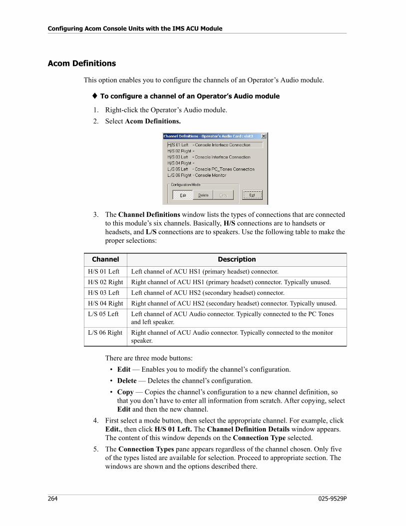
Configuring Acom Console Units with the IMS ACU Module
264 025-9529P
Acom Definitions
This option enables you to configure the channels of an Operator’s Audio module.
♦ To configure a channel of an Operator’s Audio module
1. Right-click the Operator’s Audio module.
2. Select Acom Definitions.
3. The Channel Definitions window lists the types of connections that are connected to this module’s six channels. Basically, H/S connections are to handsets or headsets, and L/S connections are to speakers. Use the following table to make the proper selections:
There are three mode buttons:
• Edit — Enables you to modify the channel’s configuration.
• Delete — Deletes the channel’s configuration.
• Copy — Copies the channel’s configuration to a new channel definition, so that you don’t have to enter all information from scratch. After copying, select Edit and then the new channel.
4. First select a mode button, then select the appropriate channel. For example, click Edit., then click H/S 01 Left. The Channel Definition Details window appears. The content of this window depends on the Connection Type selected.
5. The Connection Types pane appears regardless of the channel chosen. Only five of the types listed are available for selection. Proceed to appropriate section. The windows are shown and the options described there.
Channel Description
H/S 01 Left Left channel of ACU HS1 (primary headset) connector.
H/S 02 Right Right channel of ACU HS1 (primary headset) connector. Typically unused.
H/S 03 Left Left channel of ACU HS2 (secondary headset) connector.
H/S 04 Right Right channel of ACU HS2 (secondary headset) connector. Typically unused.
L/S 05 Left Left channel of ACU Audio connector. Typically connected to the PC Tones and left speaker.
L/S 06 Right Right channel of ACU Audio connector. Typically connected to the monitor speaker.
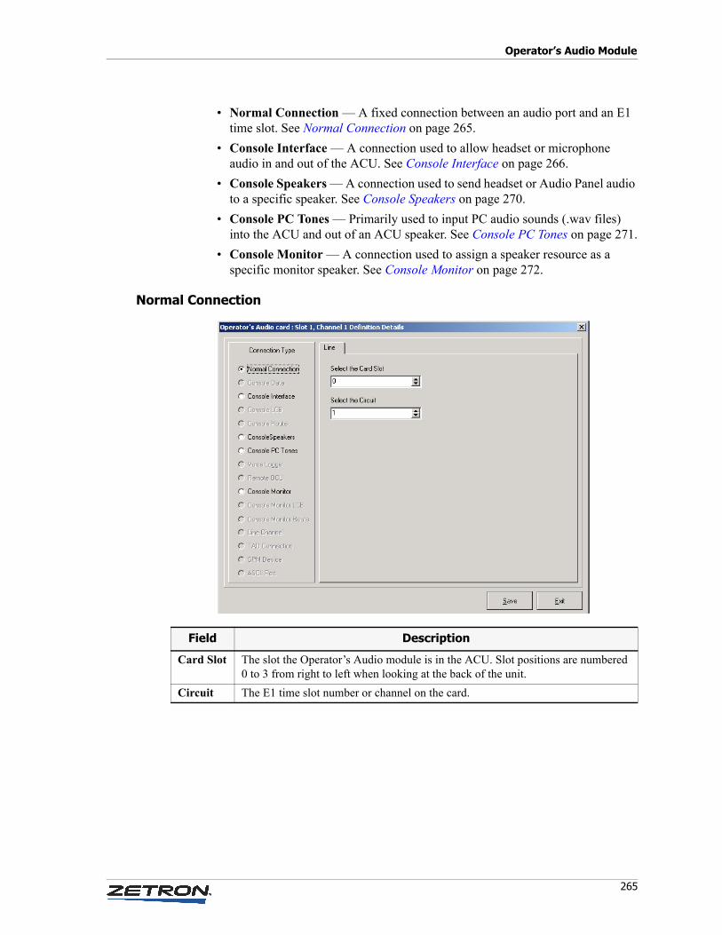
265
Operator’s Audio Module
• Normal Connection — A fixed connection between an audio port and an E1 time slot. See Normal Connection on page 265.
• Console Interface — A connection used to allow headset or microphone audio in and out of the ACU. See Console Interface on page 266.
• Console Speakers — A connection used to send headset or Audio Panel audio to a specific speaker. See Console Speakers on page 270.
• Console PC Tones — Primarily used to input PC audio sounds (.wav files) into the ACU and out of an ACU speaker. See Console PC Tones on page 271.
• Console Monitor — A connection used to assign a speaker resource as a specific monitor speaker. See Console Monitor on page 272.
Normal Connection
Field Description
Card Slot The slot the Operator’s Audio module is in the ACU. Slot positions are numbered 0 to 3 from right to left when looking at the back of the unit.
Circuit The E1 time slot number or channel on the card.
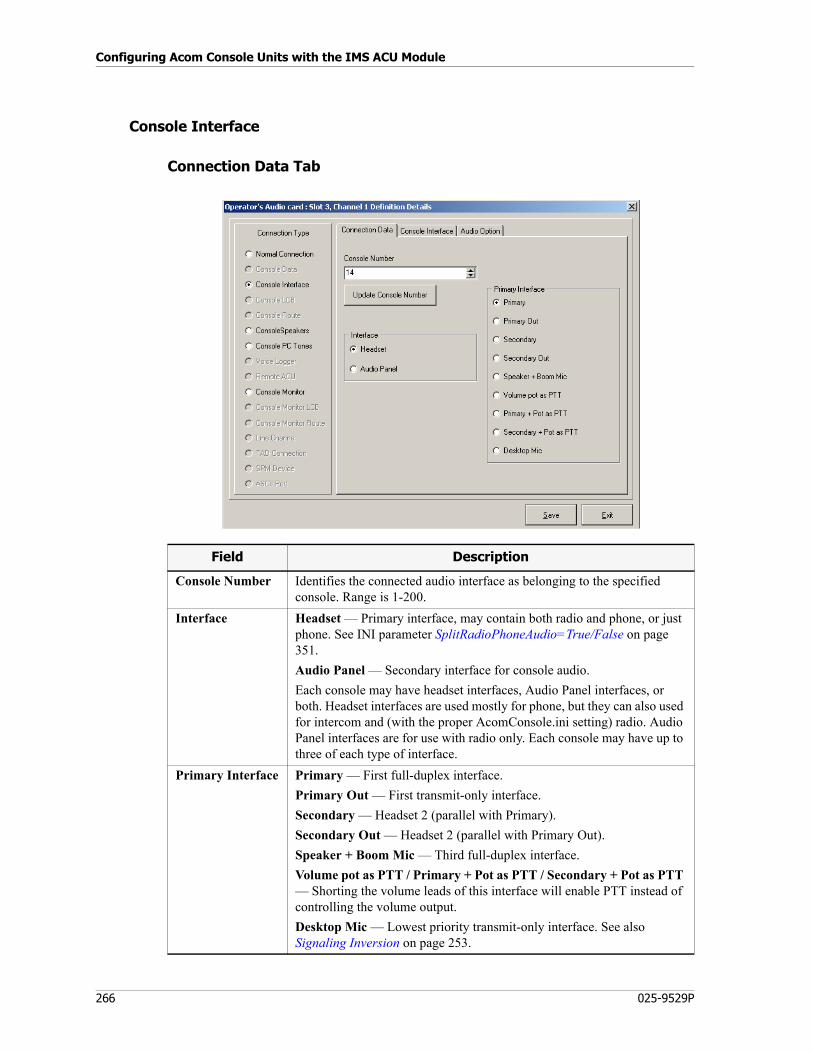
Configuring Acom Console Units with the IMS ACU Module
266 025-9529P
Console Interface
Connection Data Tab
Field Description
Console Number Identifies the connected audio interface as belonging to the specified console. Range is 1-200.
Interface Headset — Primary interface, may contain both radio and phone, or just phone. See INI parameter SplitRadioPhoneAudio=True/False on page 351.
Audio Panel — Secondary interface for console audio.
Each console may have headset interfaces, Audio Panel interfaces, or both. Headset interfaces are used mostly for phone, but they can also used for intercom and (with the proper AcomConsole.ini setting) radio. Audio Panel interfaces are for use with radio only. Each console may have up to three of each type of interface.
Primary Interface Primary — First full-duplex interface.
Primary Out — First transmit-only interface.
Secondary — Headset 2 (parallel with Primary).
Secondary Out — Headset 2 (parallel with Primary Out).
Speaker + Boom Mic — Third full-duplex interface.
Volume pot as PTT / Primary + Pot as PTT / Secondary + Pot as PTT — Shorting the volume leads of this interface will enable PTT instead of controlling the volume output.
Desktop Mic — Lowest priority transmit-only interface. See also Signaling Inversion on page 253.
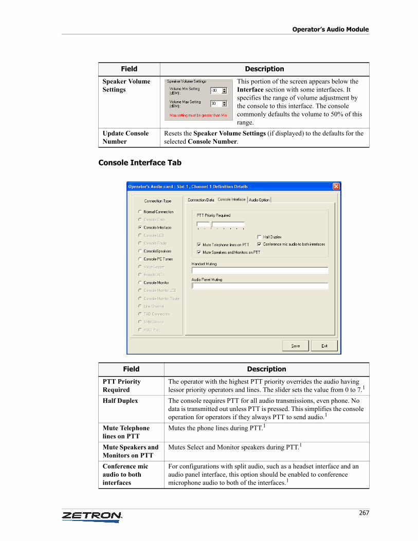
267
Operator’s Audio Module
Console Interface Tab
Speaker Volume Settings
This portion of the screen appears below the Interface section with some interfaces. It specifies the range of volume adjustment by the console to this interface. The console commonly defaults the volume to 50% of this range.
Update Console Number
Resets the Speaker Volume Settings (if displayed) to the defaults for the selected Console Number.
Field Description
Field Description
PTT Priority Required
The operator with the highest PTT priority overrides the audio having lessor priority operators and lines. The slider sets the value from 0 to 7.1
Half Duplex The console requires PTT for all audio transmissions, even phone. No data is transmitted out unless PTT is pressed. This simplifies the console operation for operators if they always PTT to send audio.1
Mute Telephone lines on PTT
Mutes the phone lines during PTT.1
Mute Speakers and Monitors on PTT
Mutes Select and Monitor speakers during PTT.1
Conference mic audio to both interfaces
For configurations with split audio, such as a headset interface and an audio panel interface, this option should be enabled to conference microphone audio to both of the interfaces.1
Configuring Acom Console Units with the IMS ACU Module
268 025-9529P
1 Conference calls with radio and phone move audio to a single headset and require PTT.
♦ To set up console cross-mute
1. Right-click the Operator’s Audio module.
2. Select Edit.
3. Select a channel, according to the type of console cross-mute you are setting up:
a. If the cross-mute is for select audio, select H/S 01 Left - Console Interface Connection.
or
b. If the cross-mute is for monitor audio, select L/S 06 Right - Console Monitor.
4. Select the Console Interface tab.
5. In the Handset Muting field, enter the numbers of the consoles that are nearby the console you are configuring. Numbers may be entered in any order, separated by a comma (for example: 1,6,3), or you may enter a range of consecutive console numbers (for example: 2-5).
6. Click Save and Exit.
7. Click Exit.
Handset Muting Used for the console cross-mute feature. Configure with nearby console numbers to prevent their Handset audio from playing in this interface. This prevents a console operator's Handset microphone transmit audio from being heard on select speakers at nearby consoles. Enabling this feature does not override the Intercom. See To set up console cross-mute on page 268.
Audio Panel Muting
Similar to Handset Muting, but microphone audio from the specified console's Audio Panel microphone is muted here. This may allow selective muting of radio calls but not phone.
Field Description
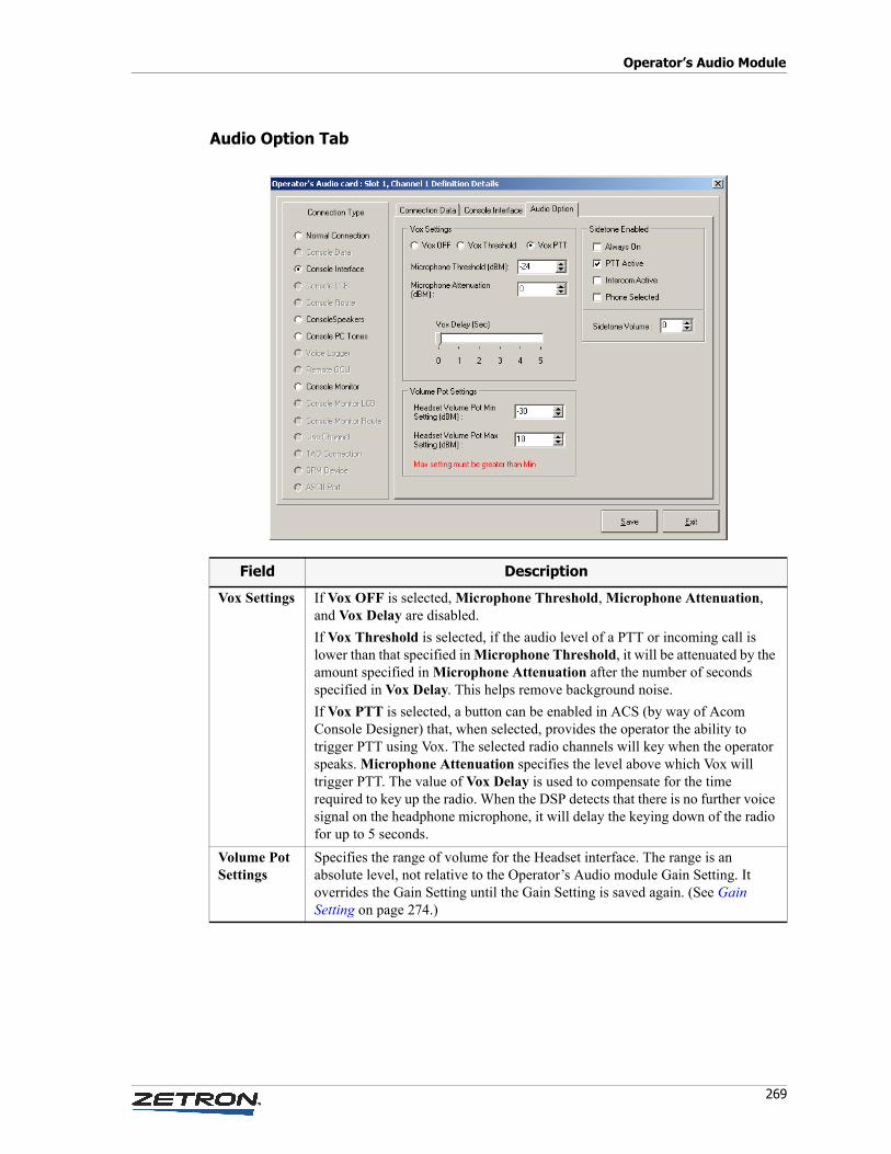
269
Operator’s Audio Module
Audio Option Tab
Field Description
Vox Settings If Vox OFF is selected, Microphone Threshold, Microphone Attenuation, and Vox Delay are disabled.
If Vox Threshold is selected, if the audio level of a PTT or incoming call is lower than that specified in Microphone Threshold, it will be attenuated by the amount specified in Microphone Attenuation after the number of seconds specified in Vox Delay. This helps remove background noise.
If Vox PTT is selected, a button can be enabled in ACS (by way of Acom Console Designer) that, when selected, provides the operator the ability to trigger PTT using Vox. The selected radio channels will key when the operator speaks. Microphone Attenuation specifies the level above which Vox will trigger PTT. The value of Vox Delay is used to compensate for the time required to key up the radio. When the DSP detects that there is no further voice signal on the headphone microphone, it will delay the keying down of the radio for up to 5 seconds.
Volume Pot Settings
Specifies the range of volume for the Headset interface. The range is an absolute level, not relative to the Operator’s Audio module Gain Setting. It overrides the Gain Setting until the Gain Setting is saved again. (See Gain Setting on page 274.)
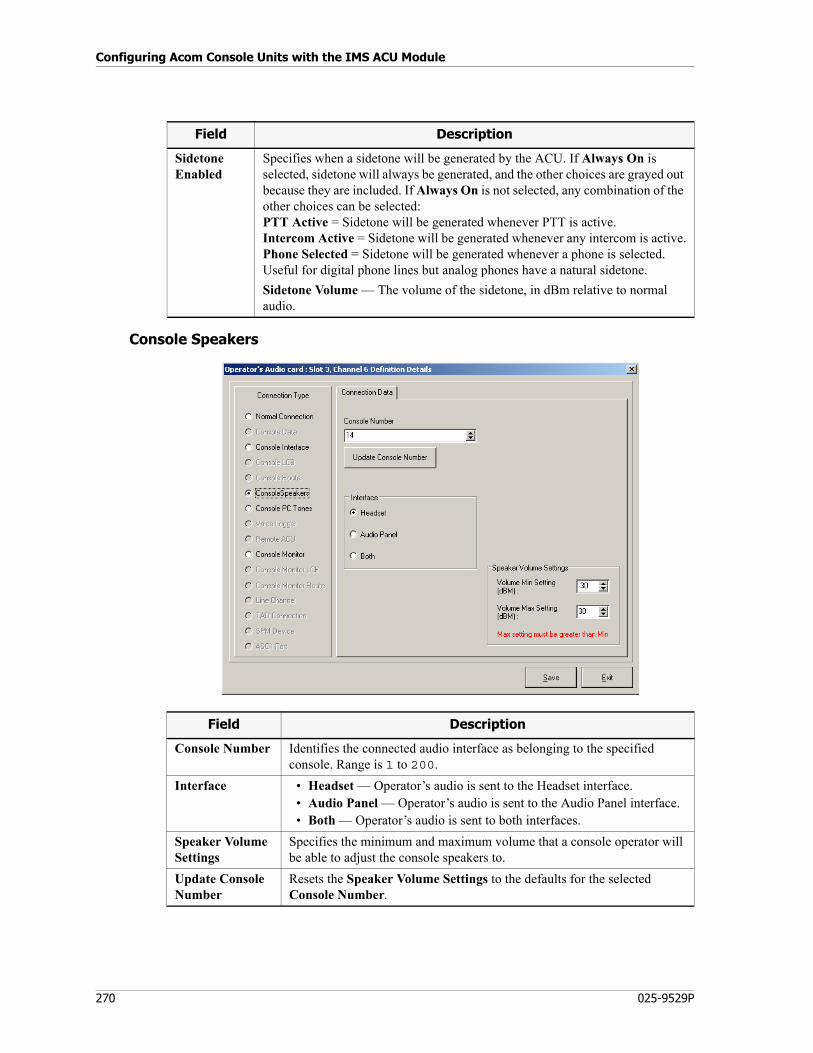
Configuring Acom Console Units with the IMS ACU Module
270 025-9529P
Console Speakers
Sidetone Enabled
Specifies when a sidetone will be generated by the ACU. If Always On is selected, sidetone will always be generated, and the other choices are grayed out because they are included. If Always On is not selected, any combination of the other choices can be selected:PTT Active = Sidetone will be generated whenever PTT is active.Intercom Active = Sidetone will be generated whenever any intercom is active.Phone Selected = Sidetone will be generated whenever a phone is selected. Useful for digital phone lines but analog phones have a natural sidetone.
Sidetone Volume — The volume of the sidetone, in dBm relative to normal audio.
Field Description
Field Description
Console Number Identifies the connected audio interface as belonging to the specified console. Range is 1 to 200.
Interface • Headset — Operator’s audio is sent to the Headset interface.• Audio Panel — Operator’s audio is sent to the Audio Panel interface.• Both — Operator’s audio is sent to both interfaces.
Speaker Volume Settings
Specifies the minimum and maximum volume that a console operator will be able to adjust the console speakers to.
Update Console Number
Resets the Speaker Volume Settings to the defaults for the selected Console Number.
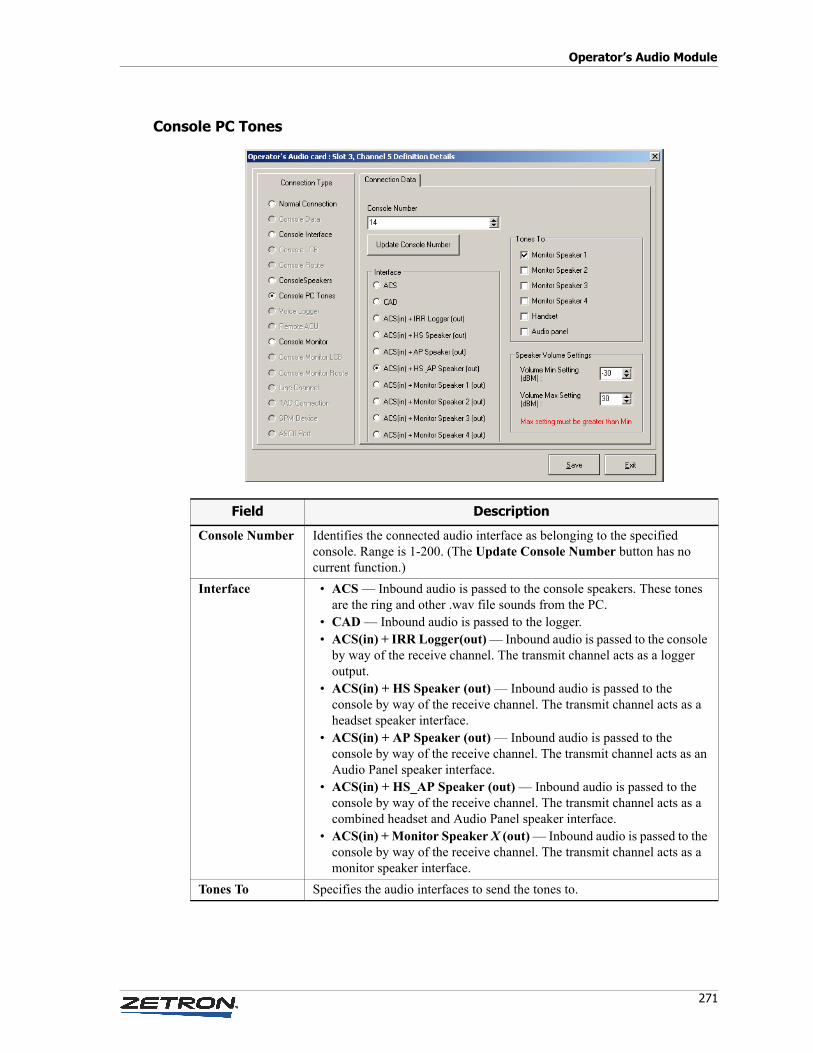
271
Operator’s Audio Module
Console PC Tones
Field Description
Console Number Identifies the connected audio interface as belonging to the specified console. Range is 1-200. (The Update Console Number button has no current function.)
Interface • ACS — Inbound audio is passed to the console speakers. These tones are the ring and other .wav file sounds from the PC.
• CAD — Inbound audio is passed to the logger.• ACS(in) + IRR Logger(out) — Inbound audio is passed to the console
by way of the receive channel. The transmit channel acts as a logger output.
• ACS(in) + HS Speaker (out) — Inbound audio is passed to the console by way of the receive channel. The transmit channel acts as a headset speaker interface.
• ACS(in) + AP Speaker (out) — Inbound audio is passed to the console by way of the receive channel. The transmit channel acts as an Audio Panel speaker interface.
• ACS(in) + HS_AP Speaker (out) — Inbound audio is passed to the console by way of the receive channel. The transmit channel acts as a combined headset and Audio Panel speaker interface.
• ACS(in) + Monitor Speaker X (out) — Inbound audio is passed to the console by way of the receive channel. The transmit channel acts as a monitor speaker interface.
Tones To Specifies the audio interfaces to send the tones to.
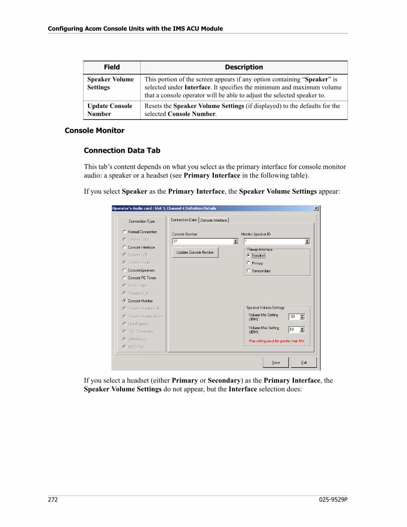
Configuring Acom Console Units with the IMS ACU Module
272 025-9529P
Console Monitor
Connection Data Tab
This tab’s content depends on what you select as the primary interface for console monitor audio: a speaker or a headset (see Primary Interface in the following table).
If you select Speaker as the Primary Interface, the Speaker Volume Settings appear:
If you select a headset (either Primary or Secondary) as the Primary Interface, the Speaker Volume Settings do not appear, but the Interface selection does:
Speaker Volume Settings
This portion of the screen appears if any option containing “Speaker” is selected under Interface. It specifies the minimum and maximum volume that a console operator will be able to adjust the selected speaker to.
Update Console Number
Resets the Speaker Volume Settings (if displayed) to the defaults for the selected Console Number.
Field Description
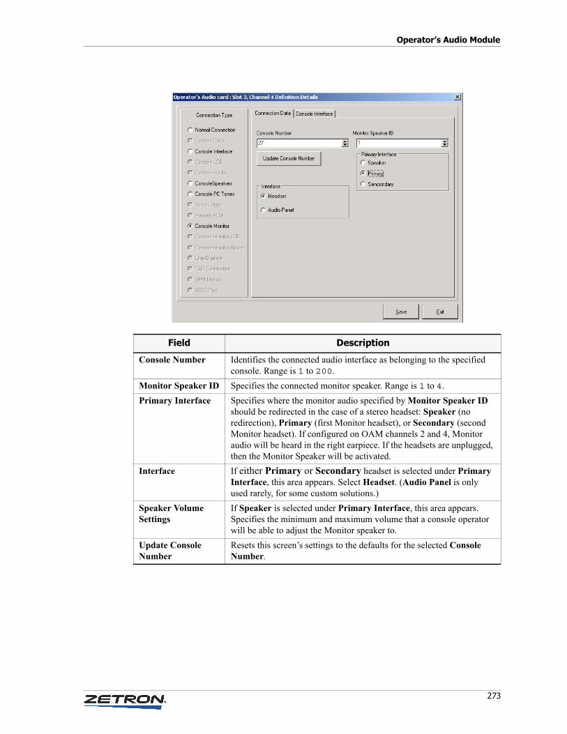
273
Operator’s Audio Module
Field Description
Console Number Identifies the connected audio interface as belonging to the specified console. Range is 1 to 200.
Monitor Speaker ID Specifies the connected monitor speaker. Range is 1 to 4.
Primary Interface Specifies where the monitor audio specified by Monitor Speaker ID should be redirected in the case of a stereo headset: Speaker (no redirection), Primary (first Monitor headset), or Secondary (second Monitor headset). If configured on OAM channels 2 and 4, Monitor audio will be heard in the right earpiece. If the headsets are unplugged, then the Monitor Speaker will be activated.
Interface If either Primary or Secondary headset is selected under Primary Interface, this area appears. Select Headset. (Audio Panel is only used rarely, for some custom solutions.)
Speaker Volume Settings
If Speaker is selected under Primary Interface, this area appears. Specifies the minimum and maximum volume that a console operator will be able to adjust the Monitor speaker to.
Update Console Number
Resets this screen’s settings to the defaults for the selected Console Number.
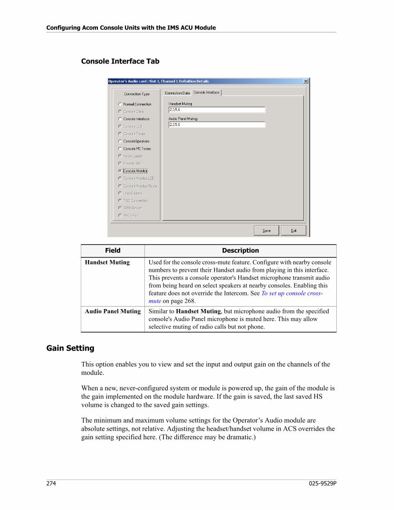
Configuring Acom Console Units with the IMS ACU Module
274 025-9529P
Console Interface Tab
Gain Setting
This option enables you to view and set the input and output gain on the channels of the module.
When a new, never-configured system or module is powered up, the gain of the module is the gain implemented on the module hardware. If the gain is saved, the last saved HS volume is changed to the saved gain settings.
The minimum and maximum volume settings for the Operator’s Audio module are absolute settings, not relative. Adjusting the headset/handset volume in ACS overrides the gain setting specified here. (The difference may be dramatic.)
Field Description
Handset Muting Used for the console cross-mute feature. Configure with nearby console numbers to prevent their Handset audio from playing in this interface. This prevents a console operator's Handset microphone transmit audio from being heard on select speakers at nearby consoles. Enabling this feature does not override the Intercom. See To set up console cross-mute on page 268.
Audio Panel Muting Similar to Handset Muting, but microphone audio from the specified console's Audio Panel microphone is muted here. This may allow selective muting of radio calls but not phone.
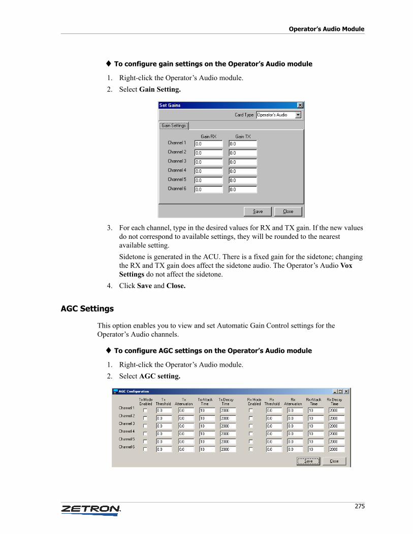
275
Operator’s Audio Module
♦ To configure gain settings on the Operator’s Audio module
1. Right-click the Operator’s Audio module.
2. Select Gain Setting.
3. For each channel, type in the desired values for RX and TX gain. If the new values do not correspond to available settings, they will be rounded to the nearest available setting.
Sidetone is generated in the ACU. There is a fixed gain for the sidetone; changing the RX and TX gain does affect the sidetone audio. The Operator’s Audio Vox Settings do not affect the sidetone.
4. Click Save and Close.
AGC Settings
This option enables you to view and set Automatic Gain Control settings for the Operator’s Audio channels.
♦ To configure AGC settings on the Operator’s Audio module
1. Right-click the Operator’s Audio module.
2. Select AGC setting.
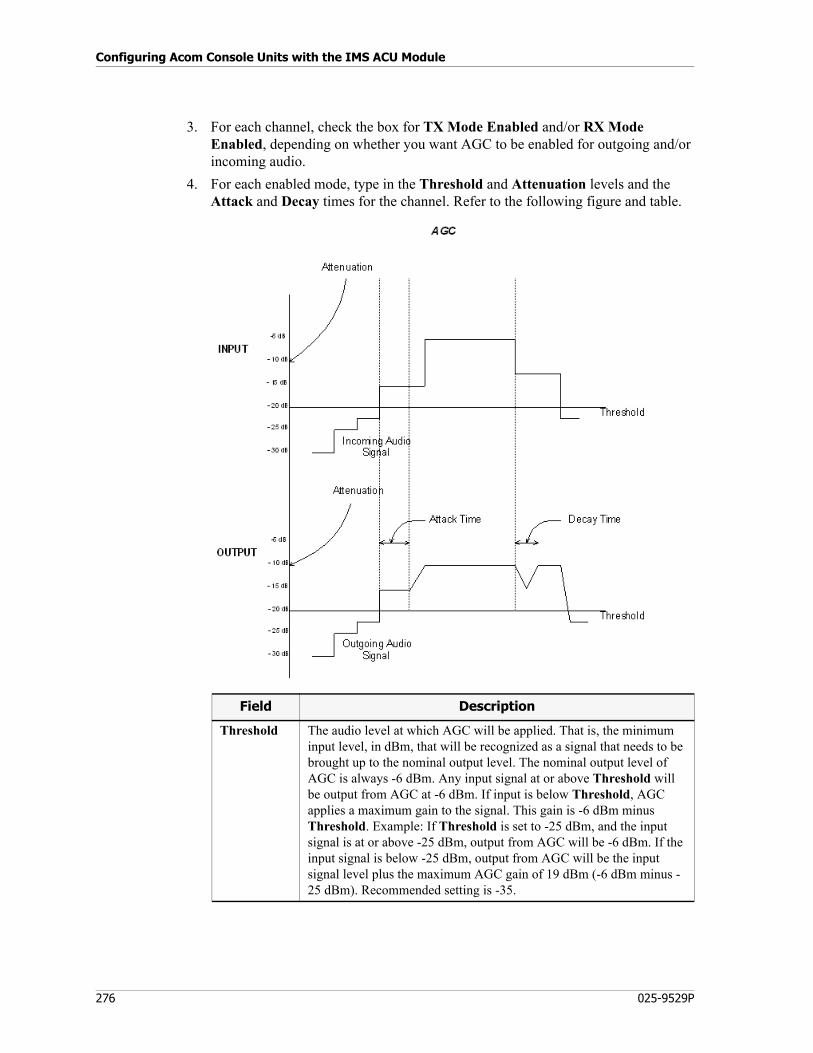
Configuring Acom Console Units with the IMS ACU Module
276 025-9529P
3. For each channel, check the box for TX Mode Enabled and/or RX Mode Enabled, depending on whether you want AGC to be enabled for outgoing and/or incoming audio.
4. For each enabled mode, type in the Threshold and Attenuation levels and the Attack and Decay times for the channel. Refer to the following figure and table.
Field Description
Threshold The audio level at which AGC will be applied. That is, the minimum input level, in dBm, that will be recognized as a signal that needs to be brought up to the nominal output level. The nominal output level of AGC is always -6 dBm. Any input signal at or above Threshold will be output from AGC at -6 dBm. If input is below Threshold, AGC applies a maximum gain to the signal. This gain is -6 dBm minus Threshold. Example: If Threshold is set to -25 dBm, and the input signal is at or above -25 dBm, output from AGC will be -6 dBm. If the input signal is below -25 dBm, output from AGC will be the input signal level plus the maximum AGC gain of 19 dBm (-6 dBm minus -25 dBm). Recommended setting is -35.
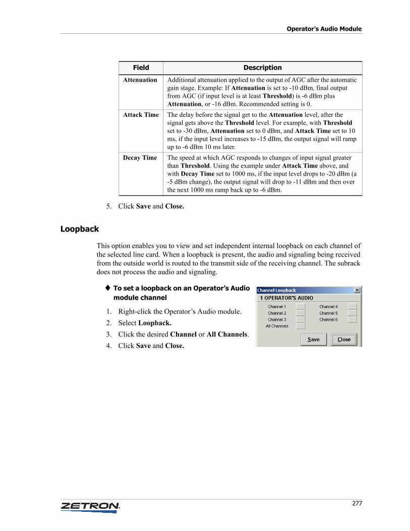
277
Operator’s Audio Module
5. Click Save and Close.
Loopback
This option enables you to view and set independent internal loopback on each channel of the selected line card. When a loopback is present, the audio and signaling being received from the outside world is routed to the transmit side of the receiving channel. The subrack does not process the audio and signaling.
♦ To set a loopback on an Operator’s Audio module channel
1. Right-click the Operator’s Audio module.
2. Select Loopback.
3. Click the desired Channel or All Channels.
4. Click Save and Close.
Attenuation Additional attenuation applied to the output of AGC after the automatic gain stage. Example: If Attenuation is set to -10 dBm, final output from AGC (if input level is at least Threshold) is -6 dBm plus Attenuation, or -16 dBm. Recommended setting is 0.
Attack Time The delay before the signal get to the Attenuation level, after the signal gets above the Threshold level. For example, with Threshold set to -30 dBm, Attenuation set to 0 dBm, and Attack Time set to 10 ms, if the input level increases to -15 dBm, the output signal will ramp up to -6 dBm 10 ms later.
Decay Time The speed at which AGC responds to changes of input signal greater than Threshold. Using the example under Attack Time above, and with Decay Time set to 1000 ms, if the input level drops to -20 dBm (a -5 dBm change), the output signal will drop to -11 dBm and then over the next 1000 ms ramp back up to -6 dBm.
Field Description

Configuring Acom Console Units with the IMS ACU Module
278 025-9529P
Installing IMS Terminal
279
Managing Network Devices with the IMS Terminal Module
This chapter describes the Terminal module of the Integrated Management System (IMS), software designed for managing and monitoring devices connected to the Acom network and for adding device driver modules (programs that enable a device to be monitored and configured) to the system as needed.
In this chapter:
• Installing IMS Terminal on page 279
• Option Setup Program on page 280
• Starting IMS Terminal on page 282
• Main Window on page 283
• Logging On and Off on page 285
• Locking the Console on page 285
• System Map Setup on page 285
• Tools on page 289
• Configuration on page 290
• Alarms on page 293
Installing IMS Terminal
♦ Prerequisites to installing IMS Terminal
1. Install Microsoft .NET Framework (.NET).
2. Install Borland Database Engine (BDE).
3. If any IMS modules are currently running (there shouldn’t be any yet), shut them down.
4. In Windows Control Panel, start BDE Administrator.
Managing Network Devices with the IMS Terminal Module
280 025-9529P
5. Click the Configuration tab.
6. Expand the Configuration tree (click the + icon next to it).
7. Expand the System tree.
8. Click INIT.
9. In the right-hand pane, click in the field next to LOCAL SHARE, where it says FALSE.
10. From the drop-down list, select TRUE.
11. Exit BDE Administrator. You will be prompted to save changes.
♦ To install IMS Terminal after the prerequisites
1. Insert the Acom CD into the CD drive.
2. The setup program should start by itself. If it doesn’t, use Windows Explorer to browse to the CD drive, then double-click setup.exe.
3. Follow the setup prompts.
4. After the installation is complete, install all device modules that IMS Terminal will be required to communicate with.
5. Once all the required device modules are installed, run the Option Setup program. This will register the device modules with IMS Terminal so that it knows which modules to load. See the next section.
Option Setup Program
The IMS Terminal Option Setup program (IMS_Terminal_Config.exe) is used to set the default communication parameters. It also registers all device modules with IMS Terminal.
To run this program, select IMS Terminal Config from the Windows Start menu. The IMS Terminal Option Setup screen appears with three tabs as shown in the following figure.
Caution! Failure to set LOCAL SHARE to TRUE in BDE Administrator may lead to the “BLOB has been modified” error message. If this were to occur, the only way to resolve it would be to uninstall all IMS modules, delete the IMS Terminal folder, and reinstall all IMS modules. All map and device definitions in IMS Terminal would need to be recreated!
!

281
Option Setup Program
Specify parameters according to the following table.
Field Description
Communication Port The serial port used to communicate with the external devices or to a router.
Baud Rate The speed used on the Communication Port. Options are 2400, 4800, 9600, 19200, and 38400 (bits per second). The default is 38400.
Connection Mode The default startup mode for IMS Terminal. The options are:
Direct to Network — used if IMS Terminal is connected directly to an ADS serial port.
Network via Modem — used if IMS Terminal is connected to a modem that is used to form a link between the RS-485 bus and all the devices on the network.
Direct to Router — used if IMS Terminal is connected directly to one of the serial ports on the IMS Router.
Router via Modem — used if IMS Terminal is connected to a modem that is used to form a link to one of the serial ports on the IMS Router.
Addressing Mode Select whether your system is using 8-bit or 16-bit addressing for Acom devices.
Modem Init String Any required initialization command string that needs to be sent to the modem to place it in its default mode of operation. Default is ATZ.
Number to Dial Phone number that needs to be dialed to connect the modem to the network or router.
Alarms to Printer If selected, all alarms and faults received from the devices on the network are sent to the printer as they occur. Alarms are simultaneously sent to the log file Alarms.txt.
Get Mode at Startup If selected, IMS Terminal will, after starting, always prompt for information about the communication port to use, the baud rate, and the connection mode (see figure below). This must be selected for standalone mode access.
Managing Network Devices with the IMS Terminal Module
282 025-9529P
Click Save and Exit. The parameter settings will be written to the IMS_Terminal.ini file.
Alarm Logging
Regardless of the alarm settings mentioned above or any printer problems, IMS Terminal always logs alarm activity. The log filename is IMSTerminal.log, and it is created in the Logs subdirectory of the IMS Terminal home directory.
When the log file reaches 1 MB in size, it is archived, and a new log file is started. Archive files have a time stamped name like:
IMSTerminal 2006-09-15 142312.log
and are created in the same directory as the log file.
Archived files older than a year are deleted.
The log format is the same as in the Alarm window except that log file opening and closing messages are inserted when IMS Terminal starts up or shuts down or log archiving occurs.
Starting IMS Terminal
1. Select IMS Terminal from the Windows Start menu, or run IMS_Terminal.exe directly from the IMS Terminal home directory. If Get Mode At Startup is not checked in IMS Terminal Config, the main window appears. Proceed to Main Window on page 283.
2. If Get Mode At Startup is checked in IMS Terminal Config, the Please Select Connection Mode window appears.
Alarms to Screen If selected, all alarms and faults received from the devices on the network are sent to a window in IMS Terminal as they occur.
Applications Check the boxes for the modules that you want to have available in IMS Terminal. IMS Terminal populates this list by searching its home directory for .aud files. Each application will run in the background and will become available when its device icon is selected in IMS Terminal.
Field Description
Caution! Do not run IMS Terminal simultaneously with others IMS applications on the same computer.
!
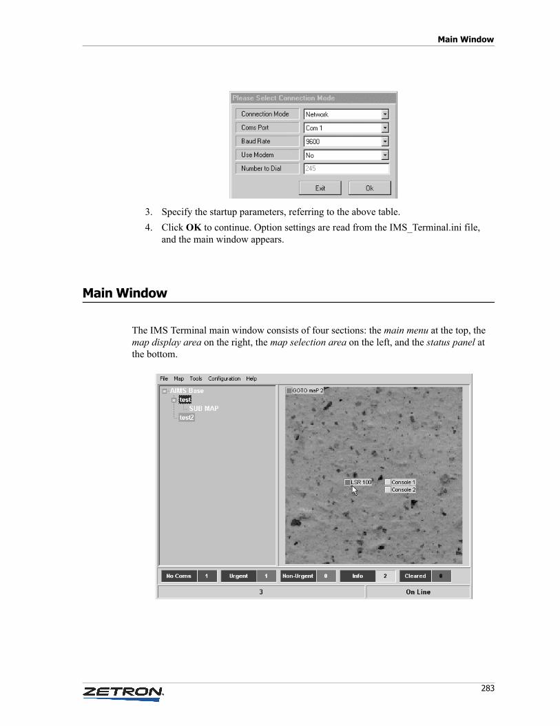
283
Main Window
3. Specify the startup parameters, referring to the above table.
4. Click OK to continue. Option settings are read from the IMS_Terminal.ini file, and the main window appears.
Main Window
The IMS Terminal main window consists of four sections: the main menu at the top, the map display area on the right, the map selection area on the left, and the status panel at the bottom.
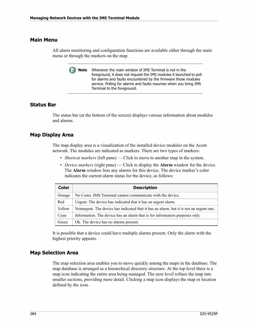
Managing Network Devices with the IMS Terminal Module
284 025-9529P
Main Menu
All alarm monitoring and configuration functions are available either through the main menu or through the markers on the map.
Status Bar
The status bar (at the bottom of the screen) displays various information about modules and alarms.
Map Display Area
The map display area is a visualization of the installed device modules on the Acom network. The modules are indicated as markers. There are two types of markers:
• Shortcut markers (left pane) — Click to move to another map in the system.
• Device markers (right pane) — Click to display the Alarm window for the device. The Alarm window lists any alarms for this device. The device marker’s color indicates the current alarm status for the device, as follows:
It is possible that a device could have multiple alarms present. Only the alarm with the highest priority appears.
Map Selection Area
The map selection area enables you to move quickly among the maps in the database. The map database is arranged as a hierarchical directory structure. At the top level there is a map icon indicating the entire area being managed. The next level refines the map into smaller sections, providing more detail. Clicking a map icon displays the map or location defined by the icon.
Note Whenever the main window of IMS Terminal is not in the foreground, it does not request the IMS modules it launched to poll for alarms and faults encountered by the firmware those modules service. Polling for alarms and faults resumes when you bring IMS Terminal to the foreground.
Color Description
Orange No Coms. IMS Terminal cannot communicate with the device.
Red Urgent. The device has indicated that it has an urgent alarm.
Yellow Nonurgent. The device has indicated that it has an alarm, but it is not an urgent one.
Cyan Information. The device has an alarm that is for information purposes only.
Green Ok. The device has no alarms present.
285
Logging On and Off
Logging On and Off
The first time IMS Terminal is started you are required to log on to the system. From the main window, select File, Logon; the default user name is USER1, and the default password is 8564888. It is recommended that the password for USER1 be changed as soon as the system is installed.
New users can be added and passwords can be changed by way of the File, Change Password menu option.
If IMS Terminal is connected to an IMS Router, the passwords from the router are used for program access. It is possible that an error message stating that the password is incorrect can appear, even though a valid user name and password were entered. This occurs if IMS Terminal cannot communicate with the router. If this happens, verify that the router is running and that the serial cable between the IMS Terminal PC and the router is present.
Selecting File, Logoff logs the current user off and resets the security level to its lowest setting.
Locking the Console
Selecting File, Lock Console stops all access to IMS Terminal but does not log off the current user. To unlock the console, you must enter the current user’s password again.
System Map Setup
The map database, illustrating the system maps for the area being managed and all devices that are present in the area, must be set up.
♦ Overview of setting up the map database
1. From the main window, select Map, Edit Map.
2. Create all the maps required to cover the area to be managed.
3. Create markers to the devices that have to be managed.
4. Create shortcuts to make it easy to move among the different maps.
5. Exit the Edit Map window.

Managing Network Devices with the IMS Terminal Module
286 025-9529P
Using the Map Builder
Select Map, Edit Map. (This option is only enabled for users that have a security level of 4 or greater.)
You can draw a map of your system area by using Map Builder. Map Builder is made up of four basic sections.
• Map area: Displays the system bitmap including any markers.
• Map Control Panel: Allows new maps to be added to the database, current maps to be edited or moved, and maps to be removed from the database.
• Marker Control Panel: Allows new device markers or shortcut markers to be added to or removed from the map
• The Map database is configured as a directory tree structure. That is, there is one map at the top level from which to move to lower levels for more details. Maps on Level 2, one level down from Level 1, would each have their own page numbers so that it is possible to select different maps on the same level.
All maps use bitmap images and can be drawn using Microsoft Paint or some similar picture editor. It is recommended that the size of the bitmaps be limited to 300x300 pixels. Larger bitmaps require more storage area and can affect the response times.
The Map area displays the current selected bitmap and also all markers placed on this image. The bitmap is resized to fill the available area while maintaining its aspect ratio.
The Map Control Panel has buttons that allows a new map to be added, the current map to be edited, or the current map to be deleted from the database. New devices can also be added, short cuts can be placed on the map, as well as basic edits.
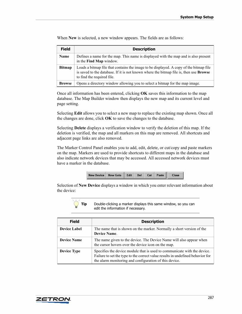
287
System Map Setup
When New is selected, a new window appears. The fields are as follows:
Once all information has been entered, clicking OK saves this information to the map database. The Map Builder window then displays the new map and its current level and page setting.
Selecting Edit allows you to select a new map to replace the existing map shown. Once all the changes are done, click OK to save the changes to the database.
Selecting Delete displays a verification window to verify the deletion of this map. If the deletion is verified, the map and all markers on this map are removed. All shortcuts and adjacent page links are also removed.
The Marker Control Panel enables you to add, edit, delete, or cut/copy and paste markers on the map. Markers are used to provide shortcuts to different maps in the database and also indicate network devices that may be accessed. All accessed network devices must have a marker in the database.
Selection of New Device displays a window in which you enter relevant information about the device:
Field Description
Name Defines a name for the map. This name is displayed with the map and is also present in the Find Map window.
Bitmap Loads a bitmap file that contains the image to be displayed. A copy of the bitmap file is saved to the database. If it is not known where the bitmap file is, then use Browse to find the required file.
Browse Opens a directory window allowing you to select a bitmap for the map image.
Tip Double-clicking a marker displays this same window, so you can edit the information if necessary.
Field Description
Device Label The name that is shown on the marker. Normally a short version of the Device Name.
Device Name The name given to the device. The Device Name will also appear when the cursor hovers over the device icon on the map.
Device Type Specifies the device module that is used to communicate with the device. Failure to set the type to the correct value results in undefined behavior for the alarm monitoring and configuration of this device.
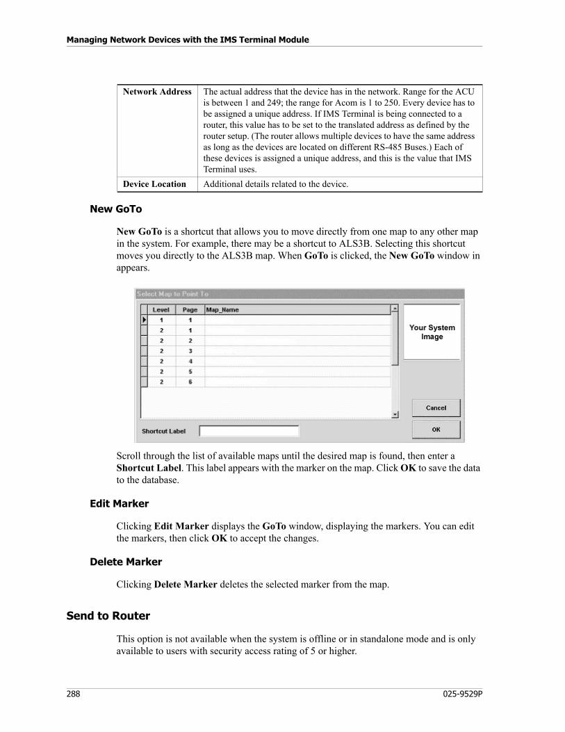
Managing Network Devices with the IMS Terminal Module
288 025-9529P
New GoTo
New GoTo is a shortcut that allows you to move directly from one map to any other map in the system. For example, there may be a shortcut to ALS3B. Selecting this shortcut moves you directly to the ALS3B map. When GoTo is clicked, the New GoTo window in appears.
Scroll through the list of available maps until the desired map is found, then enter a Shortcut Label. This label appears with the marker on the map. Click OK to save the data to the database.
Edit Marker
Clicking Edit Marker displays the GoTo window, displaying the markers. You can edit the markers, then click OK to accept the changes.
Delete Marker
Clicking Delete Marker deletes the selected marker from the map.
Send to Router
This option is not available when the system is offline or in standalone mode and is only available to users with security access rating of 5 or higher.
Network Address The actual address that the device has in the network. Range for the ACU is between 1 and 249; the range for Acom is 1 to 250. Every device has to be assigned a unique address. If IMS Terminal is being connected to a router, this value has to be set to the translated address as defined by the router setup. (The router allows multiple devices to have the same address as long as the devices are located on different RS-485 Buses.) Each of these devices is assigned a unique address, and this is the value that IMS Terminal uses.
Device Location Additional details related to the device.
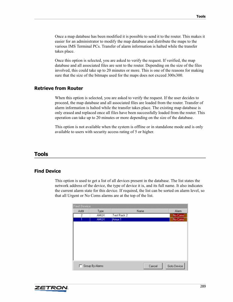
289
Tools
Once a map database has been modified it is possible to send it to the router. This makes it easier for an administrator to modify the map database and distribute the maps to the various IMS Terminal PCs. Transfer of alarm information is halted while the transfer takes place.
Once this option is selected, you are asked to verify the request. If verified, the map database and all associated files are sent to the router. Depending on the size of the files involved, this could take up to 20 minutes or more. This is one of the reasons for making sure that the size of the bitmaps used for the maps does not exceed 300x300.
Retrieve from Router
When this option is selected, you are asked to verify the request. If the user decides to proceed, the map database and all associated files are loaded from the router. Transfer of alarm information is halted while the transfer takes place. The existing map database is only erased and replaced once all files have been successfully loaded from the router. This operation can take up to 20 minutes or more depending on the size of the database.
This option is not available when the system is offline or in standalone mode and is only available to users with security access rating of 5 or higher.
Tools
Find Device
This option is used to get a list of all devices present in the database. The list states the network address of the device, the type of device it is, and its full name. It also indicates the current alarm state for this device. If required, the list can be sorted on alarm level, so that all Urgent or No Coms alarms are at the top of the list.
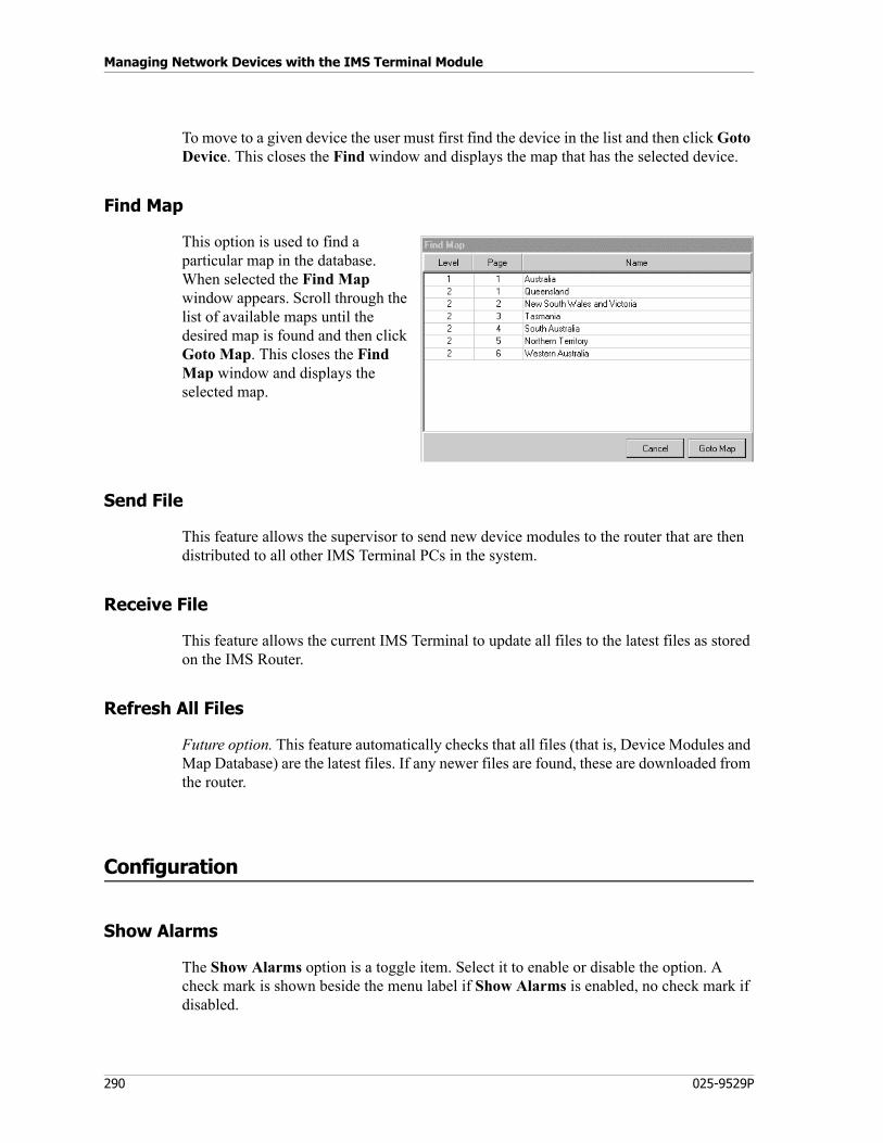
Managing Network Devices with the IMS Terminal Module
290 025-9529P
To move to a given device the user must first find the device in the list and then click Goto Device. This closes the Find window and displays the map that has the selected device.
Find Map
This option is used to find a particular map in the database. When selected the Find Map window appears. Scroll through the list of available maps until the desired map is found and then click Goto Map. This closes the Find Map window and displays the selected map.
Send File
This feature allows the supervisor to send new device modules to the router that are then distributed to all other IMS Terminal PCs in the system.
Receive File
This feature allows the current IMS Terminal to update all files to the latest files as stored on the IMS Router.
Refresh All Files
Future option. This feature automatically checks that all files (that is, Device Modules and Map Database) are the latest files. If any newer files are found, these are downloaded from the router.
Configuration
Show Alarms
The Show Alarms option is a toggle item. Select it to enable or disable the option. A check mark is shown beside the menu label if Show Alarms is enabled, no check mark if disabled.
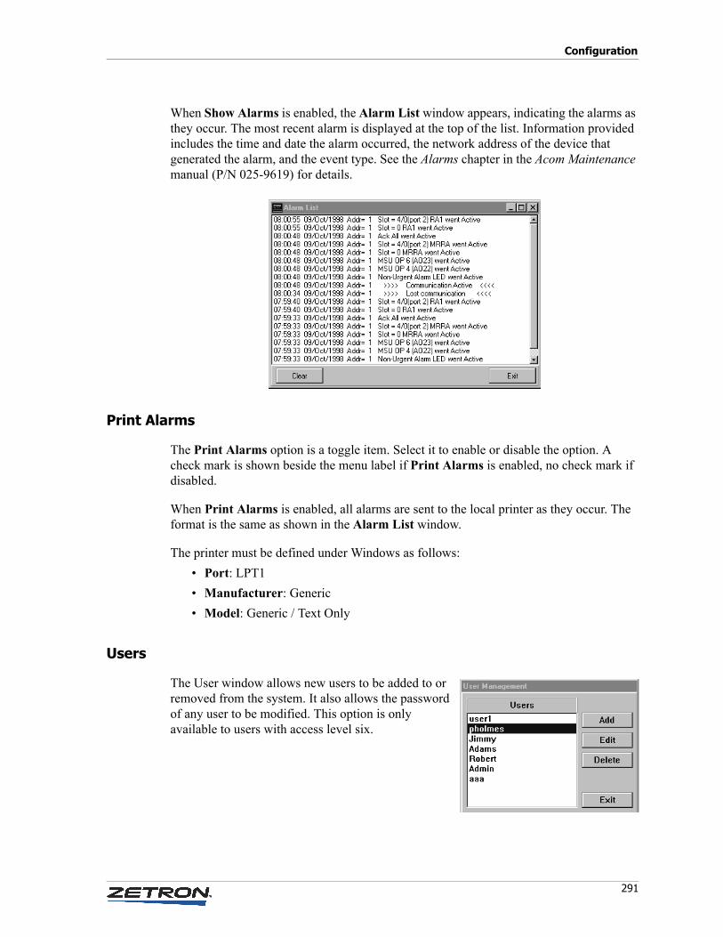
291
Configuration
When Show Alarms is enabled, the Alarm List window appears, indicating the alarms as they occur. The most recent alarm is displayed at the top of the list. Information provided includes the time and date the alarm occurred, the network address of the device that generated the alarm, and the event type. See the Alarms chapter in the Acom Maintenance manual (P/N 025-9619) for details.
Print Alarms
The Print Alarms option is a toggle item. Select it to enable or disable the option. A check mark is shown beside the menu label if Print Alarms is enabled, no check mark if disabled.
When Print Alarms is enabled, all alarms are sent to the local printer as they occur. The format is the same as shown in the Alarm List window.
The printer must be defined under Windows as follows:
• Port: LPT1
• Manufacturer: Generic
• Model: Generic / Text Only
Users
The User window allows new users to be added to or removed from the system. It also allows the password of any user to be modified. This option is only available to users with access level six.
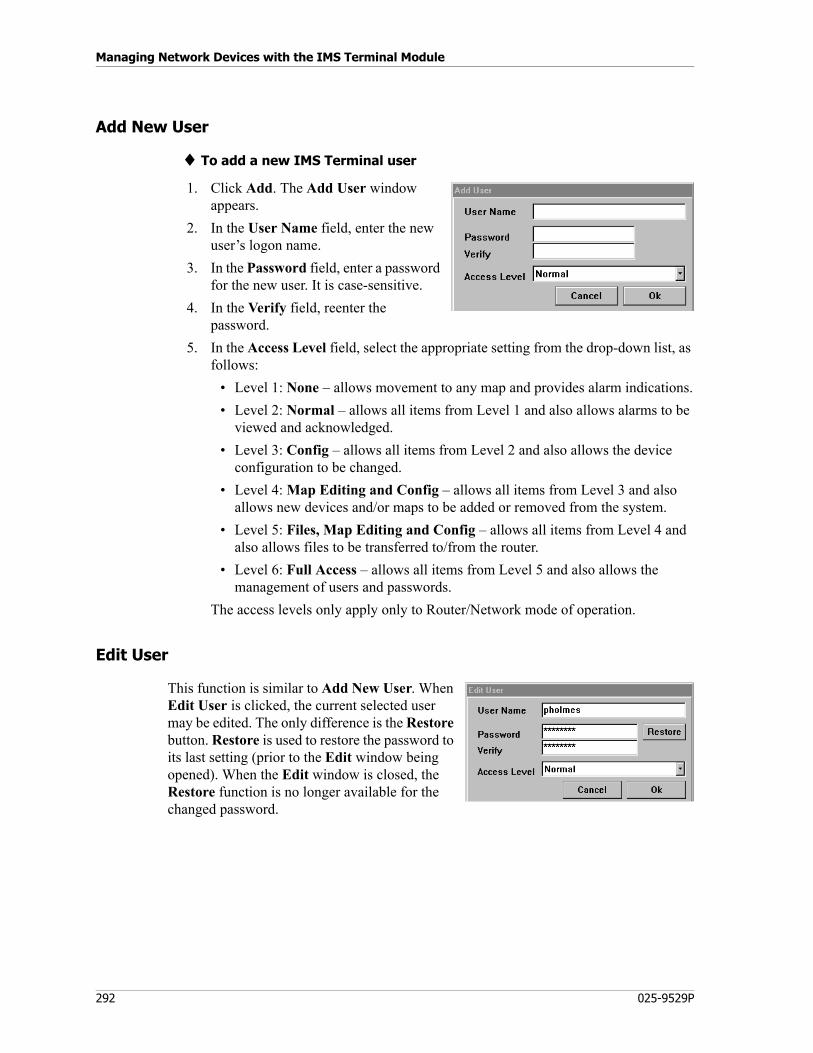
Managing Network Devices with the IMS Terminal Module
292 025-9529P
Add New User
♦ To add a new IMS Terminal user
1. Click Add. The Add User window appears.
2. In the User Name field, enter the new user’s logon name.
3. In the Password field, enter a password for the new user. It is case-sensitive.
4. In the Verify field, reenter the password.
5. In the Access Level field, select the appropriate setting from the drop-down list, as follows:
• Level 1: None – allows movement to any map and provides alarm indications.
• Level 2: Normal – allows all items from Level 1 and also allows alarms to be viewed and acknowledged.
• Level 3: Config – allows all items from Level 2 and also allows the device configuration to be changed.
• Level 4: Map Editing and Config – allows all items from Level 3 and also allows new devices and/or maps to be added or removed from the system.
• Level 5: Files, Map Editing and Config – allows all items from Level 4 and also allows files to be transferred to/from the router.
• Level 6: Full Access – allows all items from Level 5 and also allows the management of users and passwords.
The access levels only apply only to Router/Network mode of operation.
Edit User
This function is similar to Add New User. When Edit User is clicked, the current selected user may be edited. The only difference is the Restore button. Restore is used to restore the password to its last setting (prior to the Edit window being opened). When the Edit window is closed, the Restore function is no longer available for the changed password.
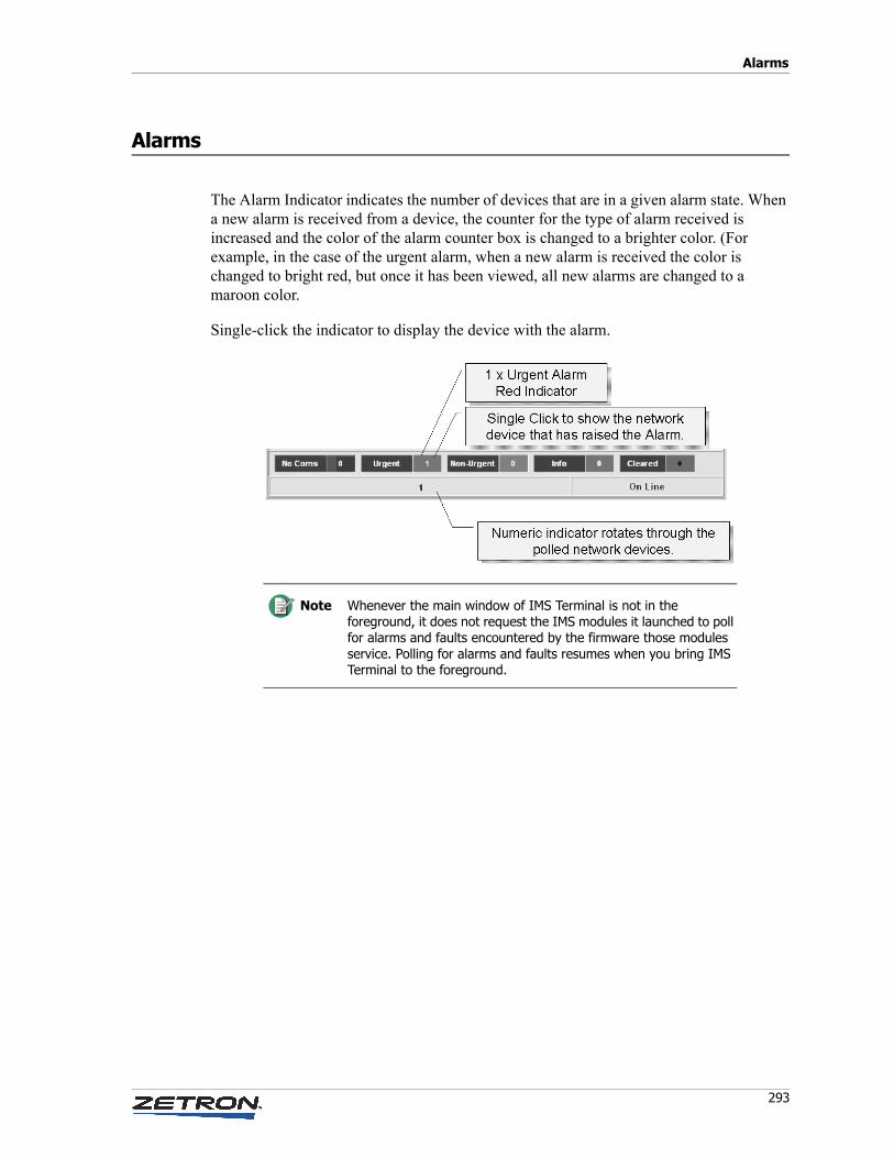
293
Alarms
Alarms
The Alarm Indicator indicates the number of devices that are in a given alarm state. When a new alarm is received from a device, the counter for the type of alarm received is increased and the color of the alarm counter box is changed to a brighter color. (For example, in the case of the urgent alarm, when a new alarm is received the color is changed to bright red, but once it has been viewed, all new alarms are changed to a maroon color.
Single-click the indicator to display the device with the alarm.
Note Whenever the main window of IMS Terminal is not in the foreground, it does not request the IMS modules it launched to poll for alarms and faults encountered by the firmware those modules service. Polling for alarms and faults resumes when you bring IMS Terminal to the foreground.

Managing Network Devices with the IMS Terminal Module
294 025-9529P
Windows 7 Configuration
295
Console Applications and Administrative Tools
This chapter describes the Windows configuration necessary for console PCs, various applications that are typically installed on console PCs, and the administrative utilities provided for managing console configurations.
This this chapter:
• Console Applications on page 296
• Administrative Tools on page 297
• Installation Order on page 297
• User Management System (UMS) on page 297
• Acom Console Software (ACS) on page 298
• Text Messaging on page 299
• Database of Operators on page 299
• Paging Configuration on page 307
• Subscriber Configuration on page 324
Windows 7 Configuration
Windows 7 User Account Control
If you are using Windows 7, User Account Control (UAC) popup requests can interfere with console operation. UAC should be disabled prior to installing Zetron software.
♦ To adjust Windows 7 UAC
1. Navigate to Control Panel, System and Security, Change User Account Control Settings.
Console Applications and Administrative Tools
296 025-9529P
2. Lower the slider all the way down to Never Notify.
3. Restart the PC if prompted to do so.
Windows 7 Touchscreen
By default, Windows 7 touchscreen interprets prolonged button presses as a right click. This interpretation prevents proper operation of controls that require a prolonged press, such as PTT. It is necessary to disable this setting in order to ensure proper operation.
♦ To disable prolonged press as right-click
1. Click the Windows Start Orb, Control Panel, Hardware and Sound, Pen and Touch.
A small list of pen and touch actions is displayed.
2. Select Press and Hold from the list of actions.
3. Click Settings.
4. Clear the checkbox next to Enable press and hold for right-clicking.
5. Click OK.
6. Click Apply, then OK.
Console Applications
Software that may be installed on console PCs includes the following:
• ACS (Acom Console Software) — This is the console operator’s graphical user interface. It must be installed on all console PCs. See Acom Console Software (ACS) on page 298 for some tips regarding basic installation and configuration. See the Acom Console Operation manual for usage.
• UMS (Zetron User Management System) — This optional program controls access to and permissions within ACS and other Zetron applications, for all users. See User Management System (UMS) on page 297 for special configuration requirements. See the User Management System Product Manual for installation and usage.
• IRR (Integrator Instant Recall Recorder) — This optional program can be used to record and play back calls. See the Integrator Instant Recall Recorder Product Manual for installation, configuration, and usage.
• Text Messaging — This optional program can be used by operators to send text messages to one another. See Text Messaging on page 299 for installation and configuration. Requires UMS.
297
Administrative Tools
Administrative Tools
These programs are all installed as a single package, called ACS Administrative Tools. They are intended to be installed only on a central, administrator’s PC:
• Acom Console Designer — utility for designing or changing the layout of the console screen. See the Acom Console Designer Product Manual.
• Acom Paging Configuration — utility for configuring page formats and instant pages. See Paging Configuration on page 307 for usage.
• Acom Profile Management — utility for configuring ACS user profiles. See Database of Operators on page 299 for usage.
• Acom Subscriber Configuration — utility for configuring radio aliases. See Subscriber Configuration on page 324 for usage.
• Zetron File Distributor — utility for distributing configuration files to PCs being used as Acom consoles. See Appendix C: Distributing Console Files on page 389 for usage.
Installation Order
These components are all installed individually. They need to be installed in the following order:
1. UMS
2. IRR
3. ACS and Administrative Tools
4. Text Messaging
User Management System (UMS)
UMS is a client-server application that is used to control which users can log on to which Zetron applications, and which users can access which features within those applications.
See the User Management System Product Manual for installation procedures. The UMS Server only needs to be installed on a central, server PC. It is advisable to also install it on a backup server. The UMS Client must be installed on every console PC on which a UMS-
Note PREREQUISITES: See Software Installation Order on page 16.
Console Applications and Administrative Tools
298 025-9529P
dependent application is also installed. Installing the UMS Server automatically installs the UMS Client on that PC, too.
To enable ACS to use UMS for logon control, the following entry needs to be in AcomConsole.ini:
[Console]EnableUMS=TrueShowLogonScreen=True
Establishing Permissions
1. Start the Zetron Account Manager (ZAM).
2. Log on as installer.
3. Under Global Settings, General Options, enable Role Permissions.
4. Under Administration, Define Permissions, create the roles you will need for Acom users. The Names must match those entered in the [Operator Types] section of AcomConsole.ini.
5. Select the appropriate permissions from each category, then click Create.
6. Under Group Permissions, Group Permissions, add the appropriate role permissions to the appropriate group types.
Acom Console Software (ACS)
The setup program needs to be executed for each console PC on which ACS will be used. It can be executed either locally or from a network drive.
During installation:
• Accept the default Folder.
• Where asked to Install AcomConsole for yourself, or for anyone who uses this computer, check Everyone.
ACS configuration is controlled by way of two things:
• The configuration file AcomConsole.ini. See Appendix A: Acom Console Software Configuration File (AcomConsole.ini) on page 327.
• The Acom Console Designer program. See the Acom Console Designer manual.
299
Text Messaging
Text Messaging
The Text Messaging (TM) module of ACS is a client-server application that enables console operators to communicate nonverbally with one another.
TM has its own setup program. Install the TM Client on every console PC that may participate in text messaging. The TM Server only needs to be installed on a central, server PC.
To enable Text Messaging in ACS, the following entry needs to be in AcomConsole.ini:
[Console]EnableTextMessaging=TrueShowLogonScreen=True...[UMS]EnableUMS=True
Use Console Designer to add a Text Messaging function key to the Acom Console form. The button will show the messaging client or flash the caption when a new message is received.
Upon first usage of the Text Messaging feature in ACS, you will need to select Edit, Configuration, and enter the name of the server PC under Server Host.
Database of Operators
This chapter describes how to update the database of operators. The two primary tools available to perform the necessary tasks are the Acom Profile Management (APM) utility and the User Management System (UMS). When either one of these programs is used, their function is not only to control who may log on to a console position, but also to allow various aspects of the user interface and console functionality to be customized based on the specific user logging on. If they were not used, the consoles would be restricted to using the same default settings contained in their .ini files all the time.
The usual preference would be to use APM since it allows you to configure more features and settings on a user-specific basis. Both programs can be used in the same system as long as the user names and passwords are the same in both databases. In this case, the APM profile is referred to for name, password, OpenSky ID, PTT Priorities, and Line Group associations, while the UMS file controls which screen forms are available to the user.
If UMS is used, the Zetron Account Management program (ZAM), as described in the User Management System Product Manual, is used to:
• Change an operator’s logon name, password, or role.
Console Applications and Administrative Tools
300 025-9529P
• Update the list of screen forms that an operator can load.
• Add an operator.
• Delete an operator.
• Show a list of users that are currently logged on to ACS.
• Log a user off remotely (force logoff).
If UMS is not used, use the Acom Profile Management program, described in this chapter, to do any of the above tasks, and to:
• Set an operator’s OpenSky ID and password.
• Specify the hunt groups that the operator can use (variants of, and/or in addition to, those defined in AcomConsole.ini).
• Set an operator's P25 SUID.
• Specify a list of console screens available to the operator.
• Specify how much Call Stack history is available on console startup.
• Specify the ACD queues that the user will be automatically attached to.
• Set the priority of an operator’s transmit audio over handset/headset and/or audio panel interfaces.
• Specify whether the person is a Supervisor that should receive alarms. (If so, this requires that the screen form loaded for this user have an Alarm button defined in it.)
• Restrict an operator from transmitting on certain lines.
• Specify user role number for routing incoming calls to specific consoles, based on Lookup Data matching the role number. See Lookup Data on page 48.
• Add Line Groups.
These extra tasks can also be available to a UMS user if the UMS account is added to Profile Management.
When you start the Acom Profile Management utility, it loads the Profiles.xml file that is in the AcomConsole Admin folder, if that file exists. If it does not, nothing is loaded and you will have to browse to the folder that contains it on that PC. You can save profile information under other filenames, but once the file is copied to a console position PC, ACS checks for the file name Profile.xml in the AcomConsole folder whenever a user attempts to log on or perform certain other actions. That is the only file for which it will check.
The main screen shows the Operator Profile window, which lists all users of ACS who have been defined in Profiles.xml.
Note Only OpenSky Mobile IDs are displayed in the Mobile ID column of the Operator Profile window. CSSI and DFSI Mobile IDs are only visible when editing a profile.
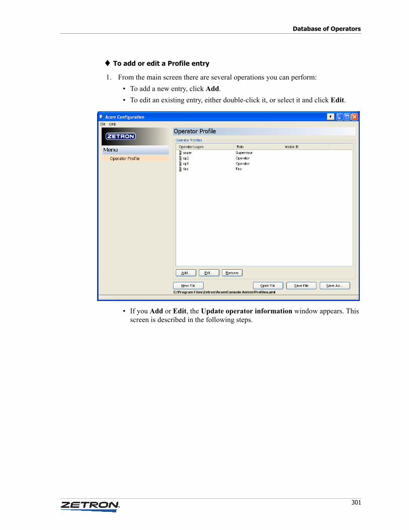
301
Database of Operators
♦ To add or edit a Profile entry
1. From the main screen there are several operations you can perform:
• To add a new entry, click Add.
• To edit an existing entry, either double-click it, or select it and click Edit.
• If you Add or Edit, the Update operator information window appears. This screen is described in the following steps.
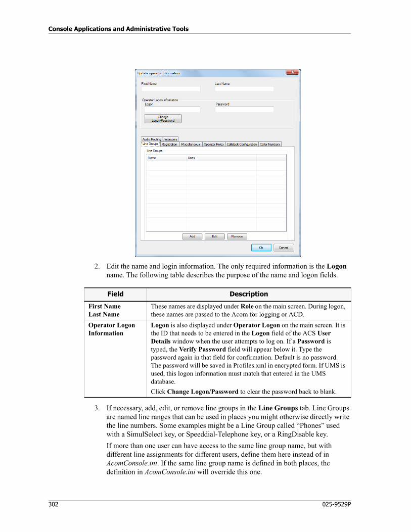
Console Applications and Administrative Tools
302 025-9529P
2. Edit the name and login information. The only required information is the Logon name. The following table describes the purpose of the name and logon fields.
3. If necessary, add, edit, or remove line groups in the Line Groups tab. Line Groups are named line ranges that can be used in places you might otherwise directly write the line numbers. Some examples might be a Line Group called “Phones” used with a SimulSelect key, or Speeddial-Telephone key, or a RingDisable key.
If more than one user can have access to the same line group name, but with different line assignments for different users, define them here instead of in AcomConsole.ini. If the same line group name is defined in both places, the definition in AcomConsole.ini will override this one.
Field Description
First NameLast Name
These names are displayed under Role on the main screen. During logon, these names are passed to the Acom for logging or ACD.
Operator LogonInformation
Logon is also displayed under Operator Logon on the main screen. It is the ID that needs to be entered in the Logon field of the ACS User Details window when the user attempts to log on. If a Password is typed, the Verify Password field will appear below it. Type the password again in that field for confirmation. Default is no password. The password will be saved in Profiles.xml in encrypted form. If UMS is used, this logon information must match that entered in the UMS database.
Click Change Logon/Password to clear the password back to blank.
303
Database of Operators
4. If using Opensky or P25, enter the registration information in the Registration tab.
5. Check the Miscellaneous tab for optional settings you may use when logged into this profile.
Field Description
OpenSkyRegistrationInformation
If an OpenSky network is in use, Mobile ID is the user’s ID for registering with the network. This is automatically passed to the network when the user logs on. If a Password is typed, the Verify Password field will appear below it. Type the password again in that field for confirmation. The password referred to here is the OpenSky network password assigned by M/A-COM Wireless. Default is no password. This logon information must match that entered for Voice End User in the OpenSky network database.
P25 Information To register with a P25 system when logged into this profile, select either CSSI or DFSI. Once selected, you can enter the Mobile ID. For CSSI, the entire SUID of WACN.SYSID.UID should be specified.
Only OpenSky Mobile IDs are displayed in the Mobile ID column of the main view. CSSI and DFSI Mobile IDs are not displayed in that view.
Field Description
ACD AutomaticQueue Attachment
If ACD is enabled, and if this user is to participate, enter the name(s) of ACD queues to which the user should be automatically attached. Use a comma to separate names. The Queues will be attached at ACD logon.
HS PriorityandAP Priority
Enter a number to specify the user’s transmit priority over the headset/handset interface (HS) and/or the audio panel (AP) interface. Range is 0 to 3. Values are relative to those specified for other users and lines.
Disable TxLine Group
Lines and/or line groups specified here cannot be used by this operator for transmitting. They cannot even be selected. They can only be monitored. Use a comma-separated list of individual line numbers, ranges of line numbers, and/or line group names.
Group On Startup Line Group
Specify the line(s) which are to be selected (grouped) at console startup.
Monitor On Startup Line Group
Specify the line(s) which are to be monitored at console startup.
Disable Emergency Display Line Group
Specify the line(s) which will have their MDC emergency alert audible disabled. This prevents dispatchers from acknowledging alarms that are not for them.
Station Turn Out Line Group
Identify which lines or line groups are Station Turn Out lines (used for Fire station alerting channels or TRHI channels).
Role Number To have Selcals directed to the user’s console according to role, enter a number here. It must be the same number entered in IMS ALS under Configure, Lookup Data. (When the Detect Type entered there is Selcal, and the Response Type is Match Acom Call ID, use this number for the R#.)
Console Applications and Administrative Tools
304 025-9529P
6. Use the Operator Roles tab to specify all screen forms that the user is entitled to open if UMS is not being used. See To add or edit a Form entry on page 307. (If UMS is being used, form names are given in the [UMS.Screens] section of AcomConsole.ini.) The forms referred to here are the .dfm files created for ACS using the Console Designer application.
7. Use the Callstack Configuration tab to control the console's subscription to call stack updates for Role-targeted calls and calls over Trunked ISDN.
Replicated ISBs Permanently activate console audio over the ISBs configured here. This ensures that a remote console's audio is available as a "transmit" source at line loggers, group connections, and monitors. The console will still replicate over all ISBs and is still accessible at all sites.
Supervisor Check this box if the user has supervisor rights to alarms.
Field Description
Note Trunked ISDN calls set the Role to the incoming Trunk Group unless changed in the Lookup Data menu of the ALS. Other calls can target operator Roles using Lookup Data. By sending calls to Roles, you overwrite the default call subscription and can send the call stack message to a group of consoles who subscribe to the Role using this menu. Not only does this menu determine if the console receives calls for the subscribed Role, but also determines what call stack lists will receive the calls. It allows the installer to determine what Roles goes to what call stack based on the operator's logon rather than hard coding it into a call stack XML config file.
Field Description
Callstack Startup History (seconds)
Upon login, the console displays historical calls as far back as this setting allows. The valid range is 0 to 86400. If set to 0, the call stack shows no calls prior to login but will show call activity from that point forward. If set to 86400 it will show historical calls from the past 24 hrs.
There are other separate features that may limit the historical calls displayed even if they fall within the configured time. For example, the ADS can expire old calls independent of this setting, and the call stack itself has a limit on the maximum number of calls it can display.
Call Handler Choose to have either the Logon Name or the Console ID displayed in callstacks for PTT ID or trunked ISDN calls.
305
Database of Operators
8. The Caller Numbers tab is used to populate custom outgoing Caller ID numbers for trunked ISDN lines. When users make an outgoing call on a trunked ISDN lines, they can pick a caller ID name and number to be sent.
Subscriptions The Subscriptions area is used to configure the console’s subscriptions to call stack updates.
Configure the Callstack Name here to match the callstack’s Callstack Name in Console Designer.
To recieve normal calls, set the Type to Role. To selectivly just receive calls that reach the overflow timer, set the Type to Role Overflow (if a call has been in the system unanswered for a period of time, an Overflow subscription may be added by the Lookup Data and send the calls to more consoles than would normally receive the call stack entry).
Set the ID to match the Role number (1-2499). For Trunked ISDN calls the Role will default to the Incoming TrunkGroup. Other calls like analog telephone do not have a default Role but can be assigned to a Role using Lookup Data in the ALS. It is possible for a console operator to transfer a call to a Role using the Transfer Destination function key. You may enter multiple Roles separated by commas, or ranges with a dash.
Field Description
Tip To receive both normal and overflow calls for Role 1, create two Role subscriptions in ths menu; one for Role 1 and another for Role 1 Overflow.
Field Description
Name The name to send.
Caller Number The number to send.
Trunk Groups This is a comma-separated list and/or a hyphen-separated range of trunk group numbers. The trunk groups configured for a particular name/number are used to filter the list seen by the users when they select a line to use.
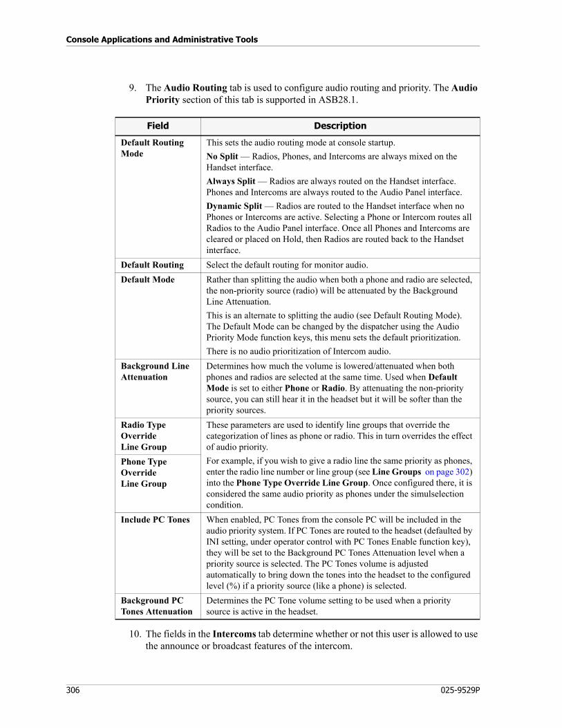
Console Applications and Administrative Tools
306 025-9529P
9. The Audio Routing tab is used to configure audio routing and priority. The Audio Priority section of this tab is supported in ASB28.1.
10. The fields in the Intercoms tab determine whether or not this user is allowed to use the announce or broadcast features of the intercom.
Field Description
Default Routing Mode
This sets the audio routing mode at console startup.
No Split — Radios, Phones, and Intercoms are always mixed on the Handset interface.
Always Split — Radios are always routed on the Handset interface. Phones and Intercoms are always routed to the Audio Panel interface.
Dynamic Split — Radios are routed to the Handset interface when no Phones or Intercoms are active. Selecting a Phone or Intercom routes all Radios to the Audio Panel interface. Once all Phones and Intercoms are cleared or placed on Hold, then Radios are routed back to the Handset interface.
Default Routing Select the default routing for monitor audio.
Default Mode Rather than splitting the audio when both a phone and radio are selected, the non-priority source (radio) will be attenuated by the Background Line Attenuation.
This is an alternate to splitting the audio (see Default Routing Mode). The Default Mode can be changed by the dispatcher using the Audio Priority Mode function keys, this menu sets the default prioritization.
There is no audio prioritization of Intercom audio.
Background Line Attenuation
Determines how much the volume is lowered/attenuated when both phones and radios are selected at the same time. Used when Default Mode is set to either Phone or Radio. By attenuating the non-priority source, you can still hear it in the headset but it will be softer than the priority sources.
Radio Type Override Line Group
These parameters are used to identify line groups that override the categorization of lines as phone or radio. This in turn overrides the effect of audio priority.
For example, if you wish to give a radio line the same priority as phones, enter the radio line number or line group (see Line Groups on page 302) into the Phone Type Override Line Group. Once configured there, it is considered the same audio priority as phones under the simulselection condition.
Phone Type Override Line Group
Include PC Tones When enabled, PC Tones from the console PC will be included in the audio priority system. If PC Tones are routed to the headset (defaulted by INI setting, under operator control with PC Tones Enable function key), they will be set to the Background PC Tones Attenuation level when a priority source is selected. The PC Tones volume is adjusted automatically to bring down the tones into the headset to the configured level (%) if a priority source (like a phone) is selected.
Background PC Tones Attenuation
Determines the PC Tone volume setting to be used when a priority source is active in the headset.
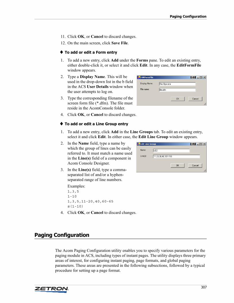
307
Paging Configuration
11. Click OK, or Cancel to discard changes.
12. On the main screen, click Save File.
♦ To add or edit a Form entry
1. To add a new entry, click Add under the Forms pane. To edit an existing entry, either double-click it, or select it and click Edit. In any case, the EditFormFile window appears.
2. Type a Display Name. This will be used in the drop-down list in the b field in the ACS User Details window when the user attempts to log on.
3. Type the corresponding filename of the screen form file (*.dfm). The file must reside in the AcomConsole folder.
4. Click OK, or Cancel to discard changes.
♦ To add or edit a Line Group entry
1. To add a new entry, click Add in the Line Groups tab. To edit an existing entry, select it and click Edit. In either case, the Edit Line Group window appears.
2. In the Name field, type a name by which the group of lines can be easily referred to. It must match a name used in the Line(s) field of a component in Acom Console Designer.
3. In the Line(s) field, type a comma-separated list of and/or a hyphen-separated range of line numbers.
Examples:1,3,51-101,3,5,11-20,40,60-65s(1-10)
4. Click OK, or Cancel to discard changes.
Paging Configuration
The Acom Paging Configuration utility enables you to specify various parameters for the paging module in ACS, including types of instant pages. The utility displays three primary areas of interest, for configuring instant paging, page formats, and global paging parameters. These areas are presented in the following subsections, followed by a typical procedure for setting up a page format.
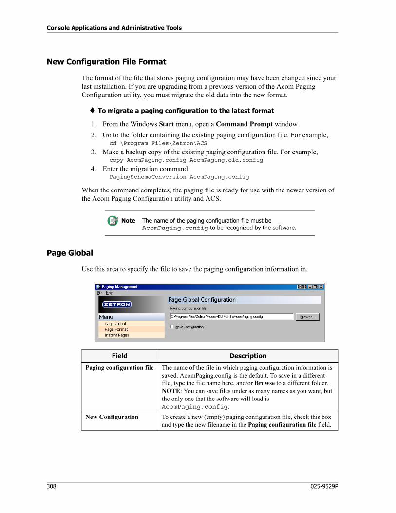
Console Applications and Administrative Tools
308 025-9529P
New Configuration File Format
The format of the file that stores paging configuration may have been changed since your last installation. If you are upgrading from a previous version of the Acom Paging Configuration utility, you must migrate the old data into the new format.
♦ To migrate a paging configuration to the latest format
1. From the Windows Start menu, open a Command Prompt window.
2. Go to the folder containing the existing paging configuration file. For example,cd \Program Files\Zetron\ACS
3. Make a backup copy of the existing paging configuration file. For example,copy AcomPaging.config AcomPaging.old.config
4. Enter the migration command:PagingSchemaConversion AcomPaging.config
When the command completes, the paging file is ready for use with the newer version of the Acom Paging Configuration utility and ACS.
Page Global
Use this area to specify the file to save the paging configuration information in.
Note The name of the paging configuration file must be AcomPaging.config to be recognized by the software.
Field Description
Paging configuration file The name of the file in which paging configuration information is saved. AcomPaging.config is the default. To save in a different file, type the file name here, and/or Browse to a different folder. NOTE: You can save files under as many names as you want, but the only one that the software will load is AcomPaging.config.
New Configuration To create a new (empty) paging configuration file, check this box and type the new filename in the Paging configuration file field.
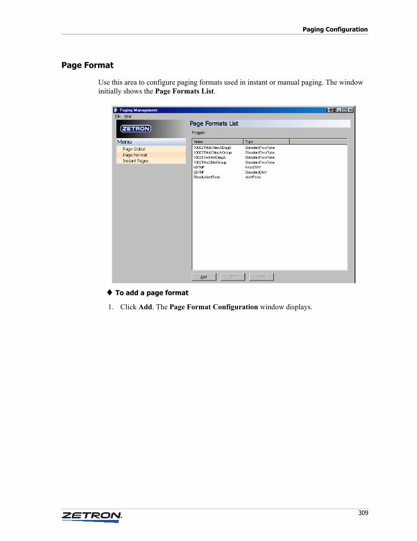
309
Paging Configuration
Page Format
Use this area to configure paging formats used in instant or manual paging. The window initially shows the Page Formats List.
♦ To add a page format
1. Click Add. The Page Format Configuration window displays.
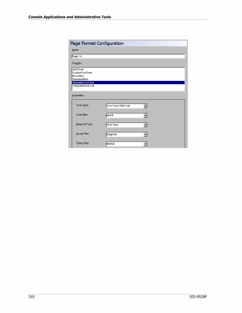
Console Applications and Administrative Tools
310 025-9529P
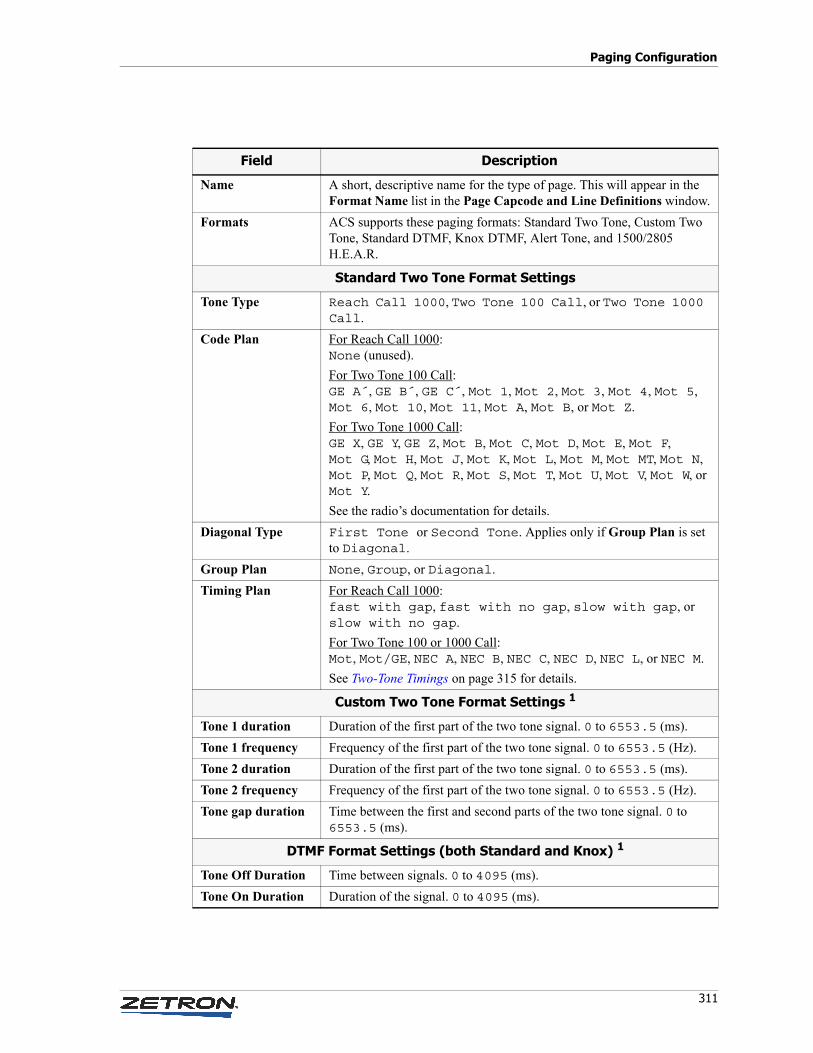
311
Paging Configuration
Field Description
Name A short, descriptive name for the type of page. This will appear in the Format Name list in the Page Capcode and Line Definitions window.
Formats ACS supports these paging formats: Standard Two Tone, Custom Two Tone, Standard DTMF, Knox DTMF, Alert Tone, and 1500/2805 H.E.A.R.
Standard Two Tone Format Settings
Tone Type Reach Call 1000, Two Tone 100 Call, or Two Tone 1000 Call.
Code Plan For Reach Call 1000: None (unused).
For Two Tone 100 Call: GE A´, GE B´, GE C´, Mot 1, Mot 2, Mot 3, Mot 4, Mot 5, Mot 6, Mot 10, Mot 11, Mot A, Mot B, or Mot Z.
For Two Tone 1000 Call: GE X, GE Y, GE Z, Mot B, Mot C, Mot D, Mot E, Mot F, Mot G, Mot H, Mot J, Mot K, Mot L, Mot M, Mot MT, Mot N, Mot P, Mot Q, Mot R, Mot S, Mot T, Mot U, Mot V, Mot W, or Mot Y.
See the radio’s documentation for details.
Diagonal Type First Tone or Second Tone. Applies only if Group Plan is set to Diagonal.
Group Plan None, Group, or Diagonal.
Timing Plan For Reach Call 1000: fast with gap, fast with no gap, slow with gap, or slow with no gap.
For Two Tone 100 or 1000 Call: Mot, Mot/GE, NEC A, NEC B, NEC C, NEC D, NEC L, or NEC M.
See Two-Tone Timings on page 315 for details.
Custom Two Tone Format Settings 1
Tone 1 duration Duration of the first part of the two tone signal. 0 to 6553.5 (ms).
Tone 1 frequency Frequency of the first part of the two tone signal. 0 to 6553.5 (Hz).
Tone 2 duration Duration of the first part of the two tone signal. 0 to 6553.5 (ms).
Tone 2 frequency Frequency of the first part of the two tone signal. 0 to 6553.5 (Hz).
Tone gap duration Time between the first and second parts of the two tone signal. 0 to 6553.5 (ms).
DTMF Format Settings (both Standard and Knox) 1
Tone Off Duration Time between signals. 0 to 4095 (ms).
Tone On Duration Duration of the signal. 0 to 4095 (ms).
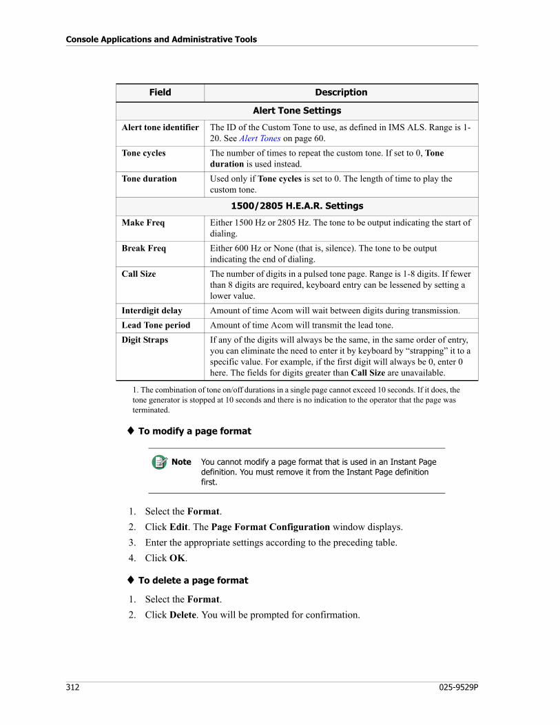
Console Applications and Administrative Tools
312 025-9529P
♦ To modify a page format
1. Select the Format.
2. Click Edit. The Page Format Configuration window displays.
3. Enter the appropriate settings according to the preceding table.
4. Click OK.
♦ To delete a page format
1. Select the Format.
2. Click Delete. You will be prompted for confirmation.
Alert Tone Settings
Alert tone identifier The ID of the Custom Tone to use, as defined in IMS ALS. Range is 1-20. See Alert Tones on page 60.
Tone cycles The number of times to repeat the custom tone. If set to 0, Tone duration is used instead.
Tone duration Used only if Tone cycles is set to 0. The length of time to play the custom tone.
1500/2805 H.E.A.R. Settings
Make Freq Either 1500 Hz or 2805 Hz. The tone to be output indicating the start of dialing.
Break Freq Either 600 Hz or None (that is, silence). The tone to be output indicating the end of dialing.
Call Size The number of digits in a pulsed tone page. Range is 1-8 digits. If fewer than 8 digits are required, keyboard entry can be lessened by setting a lower value.
Interdigit delay Amount of time Acom will wait between digits during transmission.
Lead Tone period Amount of time Acom will transmit the lead tone.
Digit Straps If any of the digits will always be the same, in the same order of entry, you can eliminate the need to enter it by keyboard by “strapping” it to a specific value. For example, if the first digit will always be 0, enter 0 here. The fields for digits greater than Call Size are unavailable.
1. The combination of tone on/off durations in a single page cannot exceed 10 seconds. If it does, the tone generator is stopped at 10 seconds and there is no indication to the operator that the page was terminated.
Note You cannot modify a page format that is used in an Instant Page definition. You must remove it from the Instant Page definition first.
Field Description
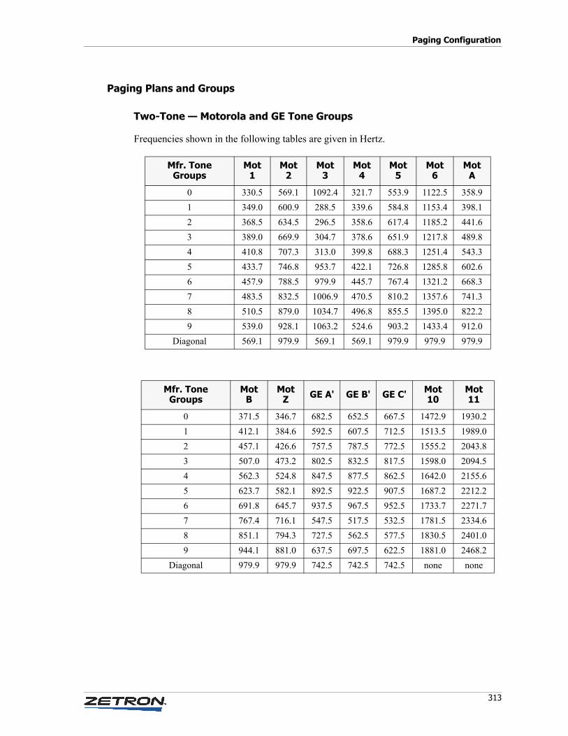
313
Paging Configuration
Paging Plans and Groups
Two-Tone — Motorola and GE Tone Groups
Frequencies shown in the following tables are given in Hertz.
Mfr. Tone Groups
Mot 1
Mot 2
Mot 3
Mot 4
Mot 5
Mot 6
Mot A
0 330.5 569.1 1092.4 321.7 553.9 1122.5 358.9
1 349.0 600.9 288.5 339.6 584.8 1153.4 398.1
2 368.5 634.5 296.5 358.6 617.4 1185.2 441.6
3 389.0 669.9 304.7 378.6 651.9 1217.8 489.8
4 410.8 707.3 313.0 399.8 688.3 1251.4 543.3
5 433.7 746.8 953.7 422.1 726.8 1285.8 602.6
6 457.9 788.5 979.9 445.7 767.4 1321.2 668.3
7 483.5 832.5 1006.9 470.5 810.2 1357.6 741.3
8 510.5 879.0 1034.7 496.8 855.5 1395.0 822.2
9 539.0 928.1 1063.2 524.6 903.2 1433.4 912.0
Diagonal 569.1 979.9 569.1 569.1 979.9 979.9 979.9
Mfr. Tone Groups
Mot B
Mot Z GE A' GE B' GE C' Mot
10Mot 11
0 371.5 346.7 682.5 652.5 667.5 1472.9 1930.2
1 412.1 384.6 592.5 607.5 712.5 1513.5 1989.0
2 457.1 426.6 757.5 787.5 772.5 1555.2 2043.8
3 507.0 473.2 802.5 832.5 817.5 1598.0 2094.5
4 562.3 524.8 847.5 877.5 862.5 1642.0 2155.6
5 623.7 582.1 892.5 922.5 907.5 1687.2 2212.2
6 691.8 645.7 937.5 967.5 952.5 1733.7 2271.7
7 767.4 716.1 547.5 517.5 532.5 1781.5 2334.6
8 851.1 794.3 727.5 562.5 577.5 1830.5 2401.0
9 944.1 881.0 637.5 697.5 622.5 1881.0 2468.2
Diagonal 979.9 979.9 742.5 742.5 742.5 none none
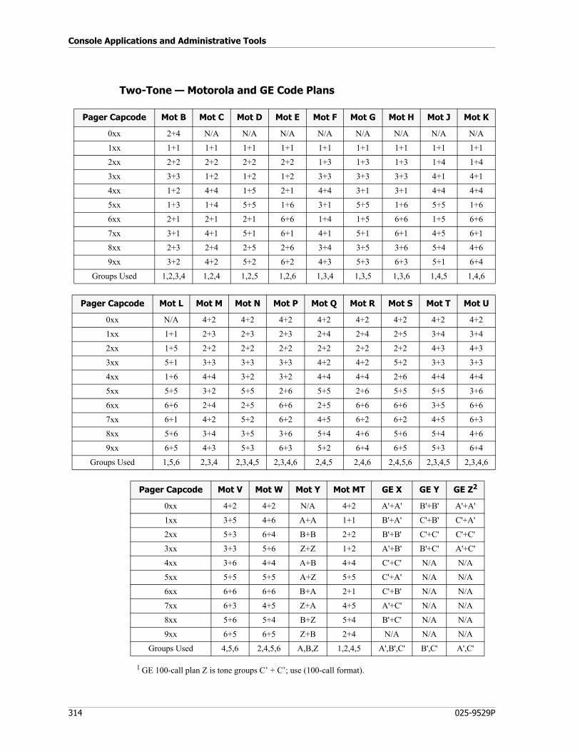
Console Applications and Administrative Tools
314 025-9529P
Two-Tone — Motorola and GE Code Plans
1 GE 100-call plan Z is tone groups C’ + C’; use (100-call format).
Pager Capcode Mot B Mot C Mot D Mot E Mot F Mot G Mot H Mot J Mot K
0xx 2+4 N/A N/A N/A N/A N/A N/A N/A N/A
1xx 1+1 1+1 1+1 1+1 1+1 1+1 1+1 1+1 1+1
2xx 2+2 2+2 2+2 2+2 1+3 1+3 1+3 1+4 1+4
3xx 3+3 1+2 1+2 1+2 3+3 3+3 3+3 4+1 4+1
4xx 1+2 4+4 1+5 2+1 4+4 3+1 3+1 4+4 4+4
5xx 1+3 1+4 5+5 1+6 3+1 5+5 1+6 5+5 1+6
6xx 2+1 2+1 2+1 6+6 1+4 1+5 6+6 1+5 6+6
7xx 3+1 4+1 5+1 6+1 4+1 5+1 6+1 4+5 6+1
8xx 2+3 2+4 2+5 2+6 3+4 3+5 3+6 5+4 4+6
9xx 3+2 4+2 5+2 6+2 4+3 5+3 6+3 5+1 6+4
Groups Used 1,2,3,4 1,2,4 1,2,5 1,2,6 1,3,4 1,3,5 1,3,6 1,4,5 1,4,6
Pager Capcode Mot L Mot M Mot N Mot P Mot Q Mot R Mot S Mot T Mot U
0xx N/A 4+2 4+2 4+2 4+2 4+2 4+2 4+2 4+2
1xx 1+1 2+3 2+3 2+3 2+4 2+4 2+5 3+4 3+4
2xx 1+5 2+2 2+2 2+2 2+2 2+2 2+2 4+3 4+3
3xx 5+1 3+3 3+3 3+3 4+2 4+2 5+2 3+3 3+3
4xx 1+6 4+4 3+2 3+2 4+4 4+4 2+6 4+4 4+4
5xx 5+5 3+2 5+5 2+6 5+5 2+6 5+5 5+5 3+6
6xx 6+6 2+4 2+5 6+6 2+5 6+6 6+6 3+5 6+6
7xx 6+1 4+2 5+2 6+2 4+5 6+2 6+2 4+5 6+3
8xx 5+6 3+4 3+5 3+6 5+4 4+6 5+6 5+4 4+6
9xx 6+5 4+3 5+3 6+3 5+2 6+4 6+5 5+3 6+4
Groups Used 1,5,6 2,3,4 2,3,4,5 2,3,4,6 2,4,5 2,4,6 2,4,5,6 2,3,4,5 2,3,4,6
Pager Capcode Mot V Mot W Mot Y Mot MT GE X GE Y GE Z2
0xx 4+2 4+2 N/A 4+2 A'+A' B'+B' A'+A'
1xx 3+5 4+6 A+A 1+1 B'+A' C'+B' C'+A'
2xx 5+3 6+4 B+B 2+2 B'+B' C'+C' C'+C'
3xx 3+3 5+6 Z+Z 1+2 A'+B' B'+C' A'+C'
4xx 3+6 4+4 A+B 4+4 C'+C' N/A N/A
5xx 5+5 5+5 A+Z 5+5 C'+A' N/A N/A
6xx 6+6 6+6 B+A 2+1 C'+B' N/A N/A
7xx 6+3 4+5 Z+A 4+5 A'+C' N/A N/A
8xx 5+6 5+4 B+Z 5+4 B'+C' N/A N/A
9xx 6+5 6+5 Z+B 2+4 N/A N/A N/A
Groups Used 4,5,6 2,4,5,6 A,B,Z 1,2,4,5 A',B',C' B',C' A',C'
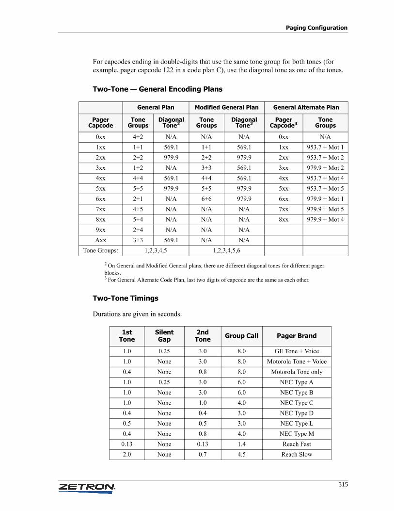
315
Paging Configuration
For capcodes ending in double-digits that use the same tone group for both tones (for example, pager capcode 122 in a code plan C), use the diagonal tone as one of the tones.
Two-Tone — General Encoding Plans
2 On General and Modified General plans, there are different diagonal tones for different pager blocks.3 For General Alternate Code Plan, last two digits of capcode are the same as each other.
Two-Tone Timings
Durations are given in seconds.
General Plan Modified General Plan General Alternate Plan
PagerCapcode
ToneGroups
DiagonalTone2
ToneGroups
DiagonalTone2
PagerCapcode3
ToneGroups
0xx 4+2 N/A N/A N/A 0xx N/A
1xx 1+1 569.1 1+1 569.1 1xx 953.7 + Mot 1
2xx 2+2 979.9 2+2 979.9 2xx 953.7 + Mot 2
3xx 1+2 N/A 3+3 569.1 3xx 979.9 + Mot 2
4xx 4+4 569.1 4+4 569.1 4xx 953.7 + Mot 4
5xx 5+5 979.9 5+5 979.9 5xx 953.7 + Mot 5
6xx 2+1 N/A 6+6 979.9 6xx 979.9 + Mot 1
7xx 4+5 N/A N/A N/A 7xx 979.9 + Mot 5
8xx 5+4 N/A N/A N/A 8xx 979.9 + Mot 4
9xx 2+4 N/A N/A N/A
Axx 3+3 569.1 N/A N/A
Tone Groups: 1,2,3,4,5 1,2,3,4,5,6
1st Tone
Silent Gap
2nd Tone Group Call Pager Brand
1.0 0.25 3.0 8.0 GE Tone + Voice
1.0 None 3.0 8.0 Motorola Tone + Voice
0.4 None 0.8 8.0 Motorola Tone only
1.0 0.25 3.0 6.0 NEC Type A
1.0 None 3.0 6.0 NEC Type B
1.0 None 1.0 4.0 NEC Type C
0.4 None 0.4 3.0 NEC Type D
0.5 None 0.5 3.0 NEC Type L
0.4 None 0.8 4.0 NEC Type M
0.13 None 0.13 1.4 Reach Fast
2.0 None 0.7 4.5 Reach Slow
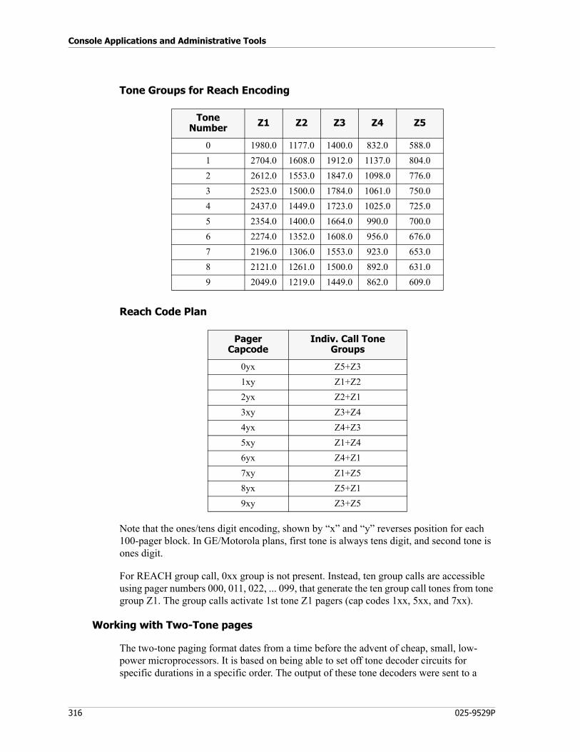
Console Applications and Administrative Tools
316 025-9529P
Tone Groups for Reach Encoding
Reach Code Plan
Note that the ones/tens digit encoding, shown by “x” and “y” reverses position for each 100-pager block. In GE/Motorola plans, first tone is always tens digit, and second tone is ones digit.
For REACH group call, 0xx group is not present. Instead, ten group calls are accessible using pager numbers 000, 011, 022, ... 099, that generate the ten group call tones from tone group Z1. The group calls activate 1st tone Z1 pagers (cap codes 1xx, 5xx, and 7xx).
Working with Two-Tone pages
The two-tone paging format dates from a time before the advent of cheap, small, low-power microprocessors. It is based on being able to set off tone decoder circuits for specific durations in a specific order. The output of these tone decoders were sent to a
Tone Number Z1 Z2 Z3 Z4 Z5
0 1980.0 1177.0 1400.0 832.0 588.0
1 2704.0 1608.0 1912.0 1137.0 804.0
2 2612.0 1553.0 1847.0 1098.0 776.0
3 2523.0 1500.0 1784.0 1061.0 750.0
4 2437.0 1449.0 1723.0 1025.0 725.0
5 2354.0 1400.0 1664.0 990.0 700.0
6 2274.0 1352.0 1608.0 956.0 676.0
7 2196.0 1306.0 1553.0 923.0 653.0
8 2121.0 1261.0 1500.0 892.0 631.0
9 2049.0 1219.0 1449.0 862.0 609.0
Pager Capcode
Indiv. Call Tone Groups
0yx Z5+Z3
1xy Z1+Z2
2yx Z2+Z1
3xy Z3+Z4
4yx Z4+Z3
5xy Z1+Z4
6yx Z4+Z1
7xy Z1+Z5
8yx Z5+Z1
9xy Z3+Z5

317
Paging Configuration
hard-wired logic circuit. If the decoders were set off for the right periods in the correct order, then the pager was set off. The first tone sent is often referred to as the “A” tone and the second tone sent as the “B” tone.
All two-tone paging schemes are organized in blocks of 100 pages. A single tone group of 10 tones allows you to make up a table with 90 unique tone combinations. The other 10 paging combinations repeat the same tone twice and would normally be used for making group calls (a single, long tone is transmitted to set off multiple pagers with a single page).
To allow larger code plans to be developed, a number of standard tone groups have been developed. These tone groups are often used in pairs to generate 1000-call code planes. The table lists the more commonly used 1000-call code plans showing the tone groups used and how they are paired up to produce the necessary number of 100-call blocks.
In some systems, there is no need to generate group-call pages, but there is a need to generate as many unique pages as possible. To support this need, the two-tone format has what are called “diagonal tones”. In any 100-call block that uses the same tone group for both tones, the diagonal tone is substituted for the second tone in any page with repeating digits (11, 22, 33, and so on). This allows the system operator to reclaim the ten group-calls in that block to be used as individual pages.
Examples
♦ To find pager tone frequencies starting with the code plan and capcode
If Motorola Code Plan C is used and the capcode is 325,
• As Table shows, Motorola Code Plane C uses the Motorola Tone Groups 1, 2 and 4.
• The leading digit 3 indicates the pages comes from the 3xx 100-call block of the code plan, which in MOT C uses Tone Groups 1 and 2, in that order, or (1+2).
• The middle digit 2 indicates the first tone of the page, which is tone 2 from Mot 1 tone group, which is 368.5 Hz.
• The third digit 5 indicates the second tone of the page, which is tone 5 from Mot 2 tone group, which is 746.8 Hz.
♦ To find the pager capcode starting with the tone frequencies
You find the Tone Groups first, then find the appropriate Code Plan within those Tone Groups.
• If the first tone is 1433.4 Hz, and the second tone is 767.4 Hz, these tones reside in the tone groups Mot 6, Tone 9 and Mot 5, Tone 6.
• Starting from the left side, work through the Code Plan list (Table ) to find the first Code Plan with a 100-call block using Motorola tone groups 6 and 5, in that order (6+5).
• Code Plan Mot L uses that combination in its 9xx block. So the pager capcode would be 996.
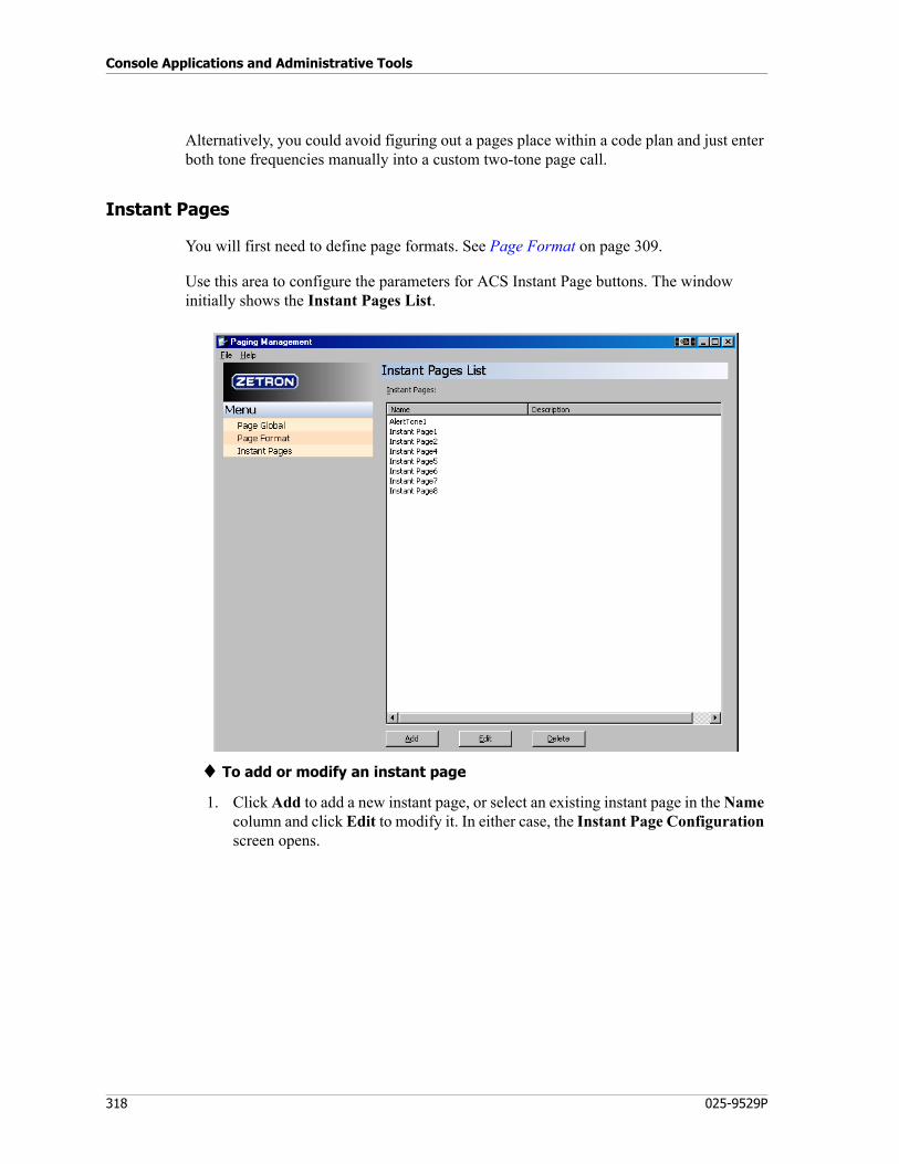
Console Applications and Administrative Tools
318 025-9529P
Alternatively, you could avoid figuring out a pages place within a code plan and just enter both tone frequencies manually into a custom two-tone page call.
Instant Pages
You will first need to define page formats. See Page Format on page 309.
Use this area to configure the parameters for ACS Instant Page buttons. The window initially shows the Instant Pages List.
♦ To add or modify an instant page
1. Click Add to add a new instant page, or select an existing instant page in the Name column and click Edit to modify it. In either case, the Instant Page Configuration screen opens.
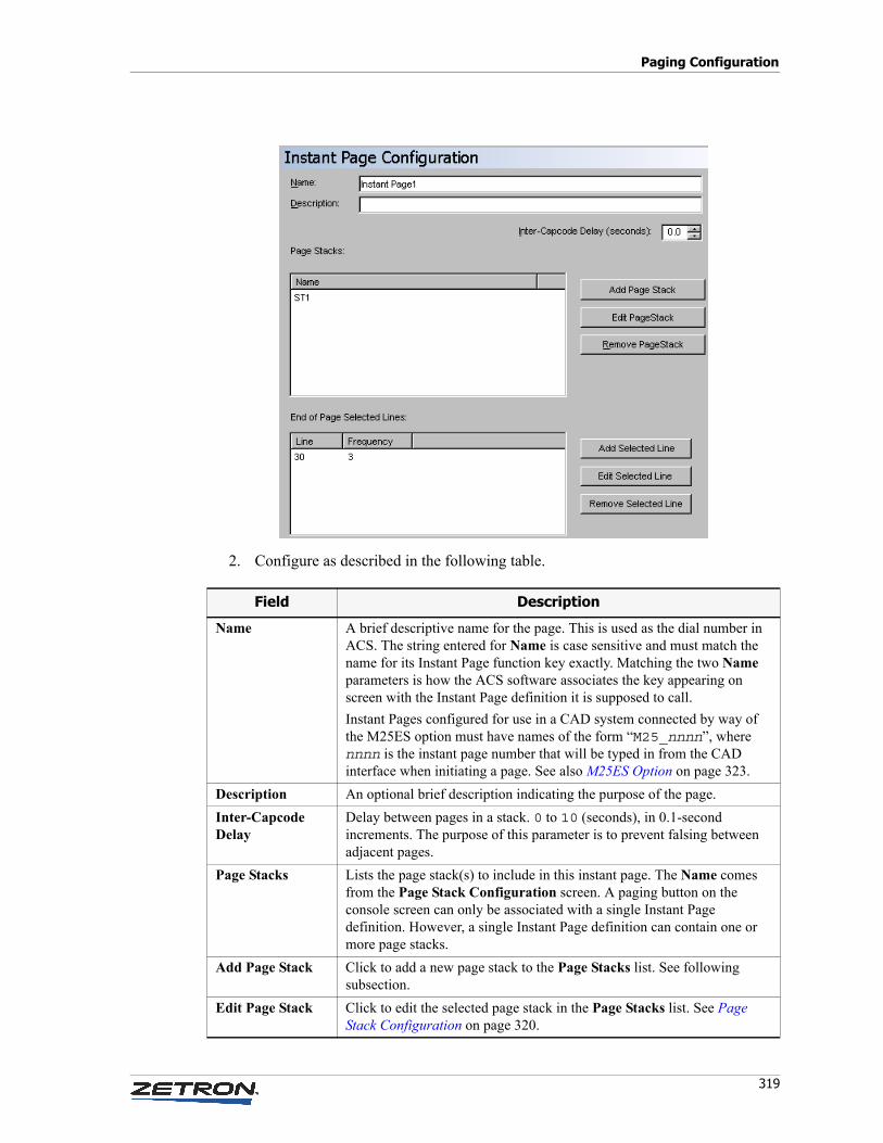
319
Paging Configuration
2. Configure as described in the following table.
Field Description
Name A brief descriptive name for the page. This is used as the dial number in ACS. The string entered for Name is case sensitive and must match the name for its Instant Page function key exactly. Matching the two Name parameters is how the ACS software associates the key appearing on screen with the Instant Page definition it is supposed to call.
Instant Pages configured for use in a CAD system connected by way of the M25ES option must have names of the form “M25_nnnn”, where nnnn is the instant page number that will be typed in from the CAD interface when initiating a page. See also M25ES Option on page 323.
Description An optional brief description indicating the purpose of the page.
Inter-CapcodeDelay
Delay between pages in a stack. 0 to 10 (seconds), in 0.1-second increments. The purpose of this parameter is to prevent falsing between adjacent pages.
Page Stacks Lists the page stack(s) to include in this instant page. The Name comes from the Page Stack Configuration screen. A paging button on the console screen can only be associated with a single Instant Page definition. However, a single Instant Page definition can contain one or more page stacks.
Add Page Stack Click to add a new page stack to the Page Stacks list. See following subsection.
Edit Page Stack Click to edit the selected page stack in the Page Stacks list. See Page Stack Configuration on page 320.
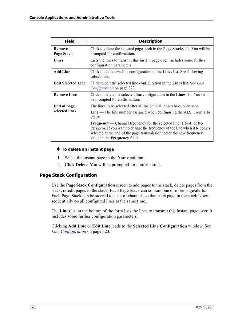
Console Applications and Administrative Tools
320 025-9529P
♦ To delete an instant page
1. Select the instant page in the Name column.
2. Click Delete. You will be prompted for confirmation.
Page Stack Configuration
Use the Page Stack Configuration screen to add pages to the stack, delete pages from the stack, or edit pages in the stack. Each Page Stack can contain one or more page/alerts. Each Page Stack can be steered to a set of channels so that each page in the stack is sent sequentially on all configured lines at the same time.
The Lines list at the bottom of the form lists the lines to transmit this instant page over. It includes some further configuration parameters.
Clicking Add Line or Edit Line leads to the Selected Line Configuration window. See Line Configuration on page 323.
RemovePage Stack
Click to delete the selected page stack in the Page Stacks list. You will be prompted for confirmation.
Lines Lists the lines to transmit this instant page over. Includes some further configuration parameters.
Add Line Click to add a new line configuration to the Lines list. See following subsection.
Edit Selected Line Click to edit the selected line configuration in the Lines list. See Line Configuration on page 323.
Remove Line Click to delete the selected line configuration in the Lines list. You will be prompted for confirmation.
End of page selected lines
The lines to be selected after all Instant Call pages have been sent.
Line — The line number assigned when configuring the ALS. From 1 to 2200.
Frequency — Channel frequency for the selected line. 1 to 4, or No Change. If you want to change the frequency of the line when it becomes selected at the end of the page transmission, enter the new frequency value in the Frequency field.
Field Description
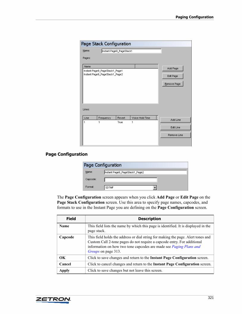
321
Paging Configuration
Page Configuration
The Page Configuration screen appears when you click Add Page or Edit Page on the Page Stack Configuration screen. Use this area to specify page names, capcodes, and formats to use in the Instant Page you are defining on the Page Configuration screen.
Field Description
Name This field lists the name by which this page is identified. It is displayed in the page stack.
Capcode This field holds the address or dial string for making the page. Alert tones and Custom Call 2-tone pages do not require a capcode entry. For additional information on how two tone capcodes are made see Paging Plans and Groups on page 313.
OK Click to save changes and return to the Instant Page Configuration screen.
Cancel Click to cancel changes and return to the Instant Page Configuration screen.
Apply Click to save changes but not leave this screen.
Console Applications and Administrative Tools
322 025-9529P
♦ To add an Instant Page definition
1. On the Page Stack Configuration screen, click the Add Page button.
2. Type a name for the page in the Name field.
3. Open the Format list and select a paging format for the page.
4. Enter a capcode or dial string in the Capcode filed if appropriate.
5. Click OK to save changes and return to the Page Stack Configuration screen.
6. Repeat steps 2 through 5 to add other page names, capcodes, and formats as appropriate.
♦ To modify an Instant Page definition
1. On the Page Stack Configuration screen, select the page you want to edit and click Edit Page button.
2. Add, delete, or modify page parameters as appropriate.
3. Click OK to save changes and return to the Page Stack Configuration screen.
♦ To delete an Instant Page definition
1. On the Page Stack Configuration screen, select the page you want to remove from the list.
2. Click Remove Page.
3. Click Apply to update the configuration file.
Lines to Select at End of Page
After the page transmission is complete, the console will select the line(s) specified as “end of page select lines” in the page’s definition. If a page stack (two or more pages sent sequentially automatically) is sent, all such lines will be selected.
On the Instant Page Configuration screen, use the End of Page Selected Lines area to specify the Line Number(s) to be automatically selected when the page is completed. You can also select a different Frequency to switch to on the line, or specify that No change is necessary.
To specify a new line, click Add Selected Line. To modify an existing line selection, click Edit Selected Line. Both choices lead to the Selected Line Configuration window. See Line Configuration on page 323.
Note Before you can add Instant Pages, you must select the paging formats that will be available and add them to the Paging Formats List.
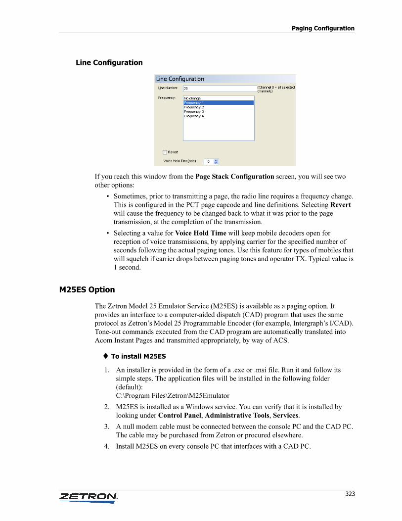
323
Paging Configuration
Line Configuration
If you reach this window from the Page Stack Configuration screen, you will see two other options:
• Sometimes, prior to transmitting a page, the radio line requires a frequency change. This is configured in the PCT page capcode and line definitions. Selecting Revert will cause the frequency to be changed back to what it was prior to the page transmission, at the completion of the transmission.
• Selecting a value for Voice Hold Time will keep mobile decoders open for reception of voice transmissions, by applying carrier for the specified number of seconds following the actual paging tones. Use this feature for types of mobiles that will squelch if carrier drops between paging tones and operator TX. Typical value is 1 second.
M25ES Option
The Zetron Model 25 Emulator Service (M25ES) is available as a paging option. It provides an interface to a computer-aided dispatch (CAD) program that uses the same protocol as Zetron’s Model 25 Programmable Encoder (for example, Intergraph’s I/CAD). Tone-out commands executed from the CAD program are automatically translated into Acom Instant Pages and transmitted appropriately, by way of ACS.
♦ To install M25ES
1. An installer is provided in the form of a .exe or .msi file. Run it and follow its simple steps. The application files will be installed in the following folder (default):C:\Program Files\Zetron\M25Emulator
2. M25ES is installed as a Windows service. You can verify that it is installed by looking under Control Panel, Administrative Tools, Services.
3. A null modem cable must be connected between the console PC and the CAD PC. The cable may be purchased from Zetron or procured elsewhere.
4. Install M25ES on every console PC that interfaces with a CAD PC.
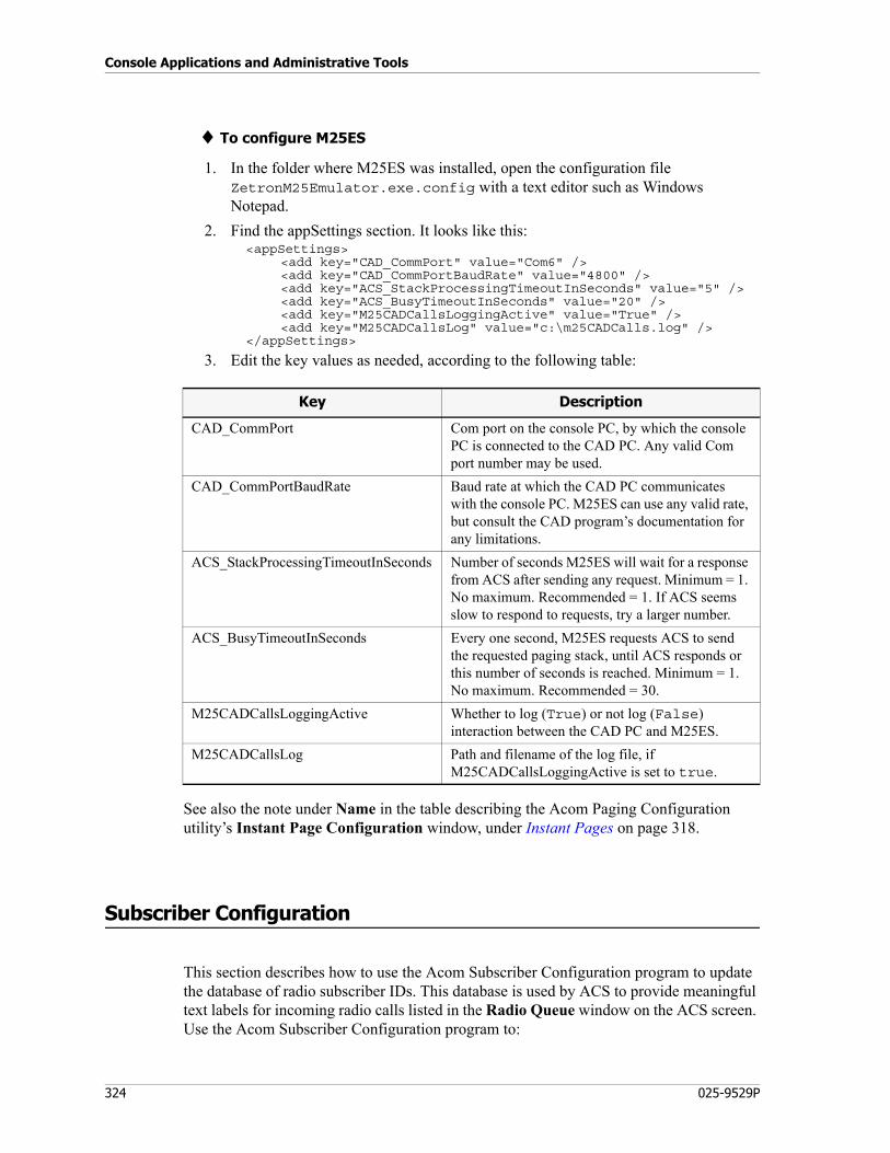
Console Applications and Administrative Tools
324 025-9529P
♦ To configure M25ES
1. In the folder where M25ES was installed, open the configuration file ZetronM25Emulator.exe.config with a text editor such as Windows Notepad.
2. Find the appSettings section. It looks like this:<appSettings>
<add key="CAD_CommPort" value="Com6" /><add key="CAD_CommPortBaudRate" value="4800" /><add key="ACS_StackProcessingTimeoutInSeconds" value="5" /><add key="ACS_BusyTimeoutInSeconds" value="20" /><add key="M25CADCallsLoggingActive" value="True" /><add key="M25CADCallsLog" value="c:\m25CADCalls.log" />
</appSettings>
3. Edit the key values as needed, according to the following table:
See also the note under Name in the table describing the Acom Paging Configuration utility’s Instant Page Configuration window, under Instant Pages on page 318.
Subscriber Configuration
This section describes how to use the Acom Subscriber Configuration program to update the database of radio subscriber IDs. This database is used by ACS to provide meaningful text labels for incoming radio calls listed in the Radio Queue window on the ACS screen. Use the Acom Subscriber Configuration program to:
Key Description
CAD_CommPort Com port on the console PC, by which the console PC is connected to the CAD PC. Any valid Com port number may be used.
CAD_CommPortBaudRate Baud rate at which the CAD PC communicates with the console PC. M25ES can use any valid rate, but consult the CAD program’s documentation for any limitations.
ACS_StackProcessingTimeoutInSeconds Number of seconds M25ES will wait for a response from ACS after sending any request. Minimum = 1. No maximum. Recommended = 1. If ACS seems slow to respond to requests, try a larger number.
ACS_BusyTimeoutInSeconds Every one second, M25ES requests ACS to send the requested paging stack, until ACS responds or this number of seconds is reached. Minimum = 1. No maximum. Recommended = 30.
M25CADCallsLoggingActive Whether to log (True) or not log (False) interaction between the CAD PC and M25ES.
M25CADCallsLog Path and filename of the log file, if M25CADCallsLoggingActive is set to true.
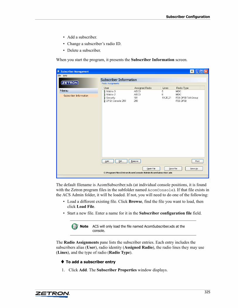
325
Subscriber Configuration
• Add a subscriber.
• Change a subscriber’s radio ID.
• Delete a subscriber.
When you start the program, it presents the Subscriber Information screen.
The default filename is AcomSubscriber.xds (at individual console positions, it is found with the Zetron program files in the subfolder named AcomConsole). If that file exists in the ACS Admin folder, it will be loaded. If not, you will need to do one of the following:
• Load a different existing file. Click Browse, find the file you want to load, then click Load File.
• Start a new file. Enter a name for it in the Subscriber configuration file field.
The Radio Assignments pane lists the subscriber entries. Each entry includes the subscribers alias (User), radio identity (Assigned Radio), the radio lines they may use (Lines), and the type of radio (Radio Type).
♦ To add a subscriber entry
1. Click Add. The Subscriber Properties window displays.
Note ACS will only load the file named AcomSubscriber.xds at the console.
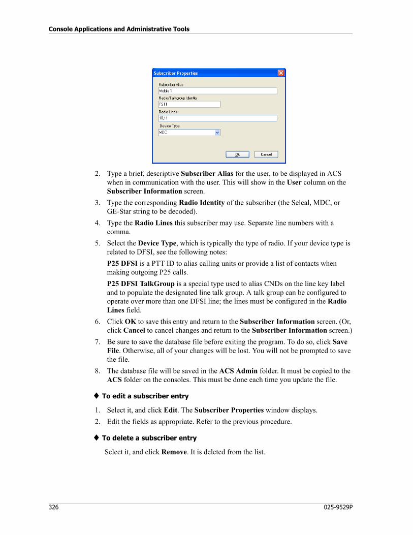
Console Applications and Administrative Tools
326 025-9529P
2. Type a brief, descriptive Subscriber Alias for the user, to be displayed in ACS when in communication with the user. This will show in the User column on the Subscriber Information screen.
3. Type the corresponding Radio Identity of the subscriber (the Selcal, MDC, or GE-Star string to be decoded).
4. Type the Radio Lines this subscriber may use. Separate line numbers with a comma.
5. Select the Device Type, which is typically the type of radio. If your device type is related to DFSI, see the following notes:
P25 DFSI is a PTT ID to alias calling units or provide a list of contacts when making outgoing P25 calls.
P25 DFSI TalkGroup is a special type used to alias CNDs on the line key label and to populate the designated line talk group. A talk group can be configured to operate over more than one DFSI line; the lines must be configured in the Radio Lines field.
6. Click OK to save this entry and return to the Subscriber Information screen. (Or, click Cancel to cancel changes and return to the Subscriber Information screen.)
7. Be sure to save the database file before exiting the program. To do so, click Save File. Otherwise, all of your changes will be lost. You will not be prompted to save the file.
8. The database file will be saved in the ACS Admin folder. It must be copied to the ACS folder on the consoles. This must be done each time you update the file.
♦ To edit a subscriber entry
1. Select it, and click Edit. The Subscriber Properties window displays.
2. Edit the fields as appropriate. Refer to the previous procedure.
♦ To delete a subscriber entry
Select it, and click Remove. It is deleted from the list.
Overview
327
Appendix A: Acom Console Software Configuration File (AcomConsole.ini)
Overview
C:\Program Files\Zetron\AcomConsole\AcomConsole.ini is the configuration file that ACS reads on startup. It can be edited with a text editor such as Notepad. Many of these parameters defined in AcomConsole.ini can also be changed from within an IMS module; changes made in IMS are written to the file.
AcomConsole.ini is used in conjunction with a console “form” file (*.dfm), which is created and edited with the Acom Console Designer program, to define the screen layout and functionality. For information about Acom Console Designer, refer to its product manual (see Associated Manuals on page 15).
[Bracketed Headings] in this chapter pertain to like-named sections of AcomConsole.ini. These headings are presented here in alphabetical order. They do not have to occur in any particular order in the file. Under each heading are all of the possible configuration entries (also in alphabetical order), descriptions of their parameters, and their valid and default values.
The default AcomConsole.ini file provided, which you will find installed in the C:\Program Files\Zetron\AcomConsole\Default folder, also includes all possible entries and their parameters. The default AcomConsole.ini and any other AcomConsole.ini files that may be supplied by Zetron are likely to be heavily commented. These comments may contain additional usage hints.
Tip Spaces may be inserted around equals signs and between parameters if desired for readability.
Note Starting with ASB25.6, obsolete entries are deprecated in this appendix, not removed.
Appendix A: Acom Console Software Configuration File (AcomConsole.ini)
328 025-9529P
[ACD Area Names]
AreaX=Name
Specifies names that can be used on console displays instead of Automatic Call Distribution (ACD) area numbers.
X = the area number, from IMS ALS. Range is 1-32.
Name = a user-friendly name for the area.
Examples:
Area1=DowntownArea2=SuburbiaArea3=East County
[ACD Queue Names]
QueueX=Name
Specifies names that can be used on console displays instead of ACD queue numbers.
X = the ACD queue number, from IMS ALS. Range is 1-32.
Name = a user-friendly name for the queue.
Examples:
Queue1=FireQueue2=PoliceQueue3=Rescue
[Acom Updates]
This section lists files that you want ACS to check for and download automatically. Each file is downloaded at startup of ACS and at regular intervals thereafter. The interval is specified by the UpdateInterval parameter option in the [Console] section (see UpdateInterval=X on page 340). This feature requires that AMI Server be installed.
DownloadX=URL
Specifies the URL of a file to download. Each file to be downloaded must be listed in a DownloadX entry, and each entry can specify only one file.
Examples:
Download1="http://imsterm/updates/alphasearch.db"
329
[Alarms]
Download2="http://imsterm/updates/acompaging.config"
[Alarms]
This section configures alarm options and the text to be displayed for various alarms when they are active.
Alarm Options
AutoClear=True/False
Specifies whether alarms should be cleared automatically if they go inactive (or if they are disabled in Acom).
True — Alarms will clear from the alarm log as they go inactive, without being Ack’d.
False — All alarms remain showing until they go inactive or are Ack’d. Default.
DisplayLineKeyCaption=True/False
Specifies whether the line button caption or the line number is used in the alarm log. Applies only to Line alarms.
True — Uses the line button caption in the alarm log.
False — Uses the line number in the alarm log. Default.
GlobalMode=True/False
Specifies whether alarms are requested for all devices and network addresses or just the specific devices/network addresses listed below under DeviceX.
True — Get alarms for all devices and all network addresses. Default.
False — Get alarms only for each defined DeviceX (see DeviceX=text on page 331).
LogAllLines=True/False
Specifies whether line alarms sent to the console as Line Status (0xB1) messages are logged in the alarm log. (Does not affect line alarms sent to the console as Alarm Status (0xAE) messages).
True — Logs line alarms that are sent as Line Status messages.
False — Does not log line alarms that are sent as Line Status messages. Default.
Note With the exception of the Sound option, these options apply only on a console that is defined as a supervisor console and that has an Alarm function button on the screen.
Appendix A: Acom Console Software Configuration File (AcomConsole.ini)
330 025-9529P
Sound=True/False
Specifies whether alarms will be audible. If enabled, a sound is played until the active alarm has been cleared or acknowledged. (The sound played is specified under [Sounds] on page 368.)
True — Enables audible alarms.
False — Disables audible alarms. Default.
SoundWithAlarmKeyOnly=True/False
Specifies whether alarms will be audible if the Alarm function button is not active. If set to True, the alarm warning sound will only play when the Alarm function button is flashing (not for Line alarms).
True — Alarms will be audible only when the Alarm button is active.
False — Alarms will be audible whether the Alarm button is active or not.
In either case, Sound must also be set to True (see Sound=True/False on page 330).
Alarm Texts
The following parameters specify the text to display for various alarm types.
X — The network address number as defined in IMS. No default.
text — The text to display. No default. If no text is specified, the alarm type will not be reported to this console.
ADSX=text
Various ADS alarms.
ALSX=text
Various ALS alarms.
ACUX=text
Various ACU alarms.
AVCX=text
Various AVC alarms.
ConsoleX=text
Specifies text to display when a particular console goes offline.
331
[Avcall]
DeviceX=text
This setting was deprecated in ASB26.1.1 and replaced by DeviceALSX, DeviceACUX, and DeviceADSX.
Specifies text to display when particular device alarms become active.
DeviceALSX=text
Specifies text to display when a particular ALS device alarm become active.
DeviceACUX=text
Specifies text to display when a particular ACU device alarm become active.
DeviceADSX=text
Specifies text to display when a particular ADS device alarm become active.
[Avcall]
The Avcall section including LeadInDelay was deprecated in ASB27.
LeadInDelay=time
Specifies the lead-in delay for AVCALL2+2 Selcal. Units are 20-ms increments. Range is 0-255 (0-5100 ms). Default is 50 (1 second).
[Call History]
ExcludeCallsOnRingDisabledLines=True/False
Specifies if calls on ringer disabled lines should be filtered out of the Call History.
True — Calls on lines with ringer disabled are filtered out.
False — Calls on lines with ringer disabled are included. Default.
HuntGroup=AcuHuntGroupX
Specifies the hunt group to be used when dialing entries in the Call History window.
X — A valid hunt group number as defined in IMS ACU.
Example:
Appendix A: Acom Console Software Configuration File (AcomConsole.ini)
332 025-9529P
HuntGroup=AcuHuntGroup5
IncludeLines=X[,X]...
Specifies the phone line numbers to include in the Call History window.
X — A valid phone line number. Multiple line numbers can be entered, comma-separated. If left blank (no values for X), all lines are included.
Examples:
IncludeLines=1,2,3,4,5IncludeLines=
[Call Transfer]
AllowPatchTransfer=True/False
Specifies whether the “patch transfer” method is enabled, which allows a console operator to transfer a phone call to an outside line by patching two phone lines together.
True — Allow patch transfer. Default.
False — Prevent patch transfer.
This option can only be used if AlternateTransfer is set to False (see next entry).
AlternateTransfer=True/False
Specifies the method to be used for transferring a call to another console. The standard method requires an intercom call to be established prior to selection of the Transfer button. The alternate method requires the Transfer button to be selected first, after which the target console is selected by way of the .
True — Use alternate method (answer call, click Transfer, Console Selection panel appears, select console, transfer goes through).
False — Use standard method (answer call, select an intercom line, call the destination console, click Transfer, transfer goes through). Default.
AllowTransferIfLineOnHold=True/False
Specifies whether a line which is on hold is allowed to be transferred.
True — Allow transfer if line is on hold.
False — Do not allow transfer if line is on hold. Default.
Note Lines will be tried in the order listed in the hunt group definition.
333
[Clean Touch Screen]
UseDynamicIfStaticDisabled=True/False
Specifies whether a call transferred to a disabled static line button can be redirected to a dynamic line button (if one exists).
True — The call can be redirected to a dynamic line button.
False — The call cannot be redirected to a dynamic line button. The call transfer will fail. Default.
[Clean Touch Screen]
AllowConnectionsToRemain=True/False
Specifies whether the user can activate screen cleaning while the console has connected and/or monitored lines.
True — Screen cleaning can be done regardless of line status.
False — Screen cleaning can be done only if there are no connected or monitored lines. Default.
[Colors]
This section specifies the colors for various buttons in various operational states. Specify the hexadecimal BGR code (NOTE: Blue-Green-Red, not Red-Green-Blue).
Examples:
FF0000 (blue)00FF00 (green)0000FF (red)000000 (white)FFFFFF (black)FFFF00 (cyan)00FFFF (yellow)FF00FF (magenta)880000 (a shade of light blue)
AudioTextColorRx=color
Applicable to radio lines only. Specifies the color of line button text when there is incoming audio or carrier detect on the line. Default is FFFFFF.
AudioTextColorTx=color
Specifies the color of line button text when there is outgoing transmission on the line. Default is 00FFFF.
Appendix A: Acom Console Software Configuration File (AcomConsole.ini)
334 025-9529P
Busy=color
Specifies the color of a line button when the line is in use by another console. Default is ACACAC.
Conference=color
Specifies the color of line buttons for lines that are in a conference. Default is the color of the Conference button.
GPLineStatusActive=color
Supports the Line Status Indicator panel for the Enroute Radio feature. Specifies the color that line status indicators assume when the status is anything other than Clear. Default is 00FFFF.
Hold=color
Specifies the color of a line button when it has been placed on hold a the local console. Default is 0080FF.
Incoming=color
Applicable to phone and intercom lines only. Specifies the color of a line button when it is not busy and there is incoming audio. Default is 00FF00.
IncomingAutoConnectIntercom=color
Specifies the color of an autoconnect line button when it is not busy and there is incoming audio. Default is 00FF00.
InstantTx=color
Specifies the color of a line button when the Instant TX function is active. No default.
LineAlarm=color
Specifies the color of a line button when it is in alarm state. Default is 0000FF.
MdcEmergencyAlert=color
Specifies the flashing background color of Emergency Alerts buttons for MDC, GE-Star, and OpenSky. Default is 0000FF.
Monitor=color
Specifies the color of a line button when the line is idle but being monitored. Default is D9B0B0. Can also be specified by DisplayMonitorFunctionColor=True/False on page 364.
335
[Colors]
MonitorMute=color
Specifies the color of a line button when the line is in Monitor Mute mode. Default is ED4E86.
NormalCarrierDetect=color
Specifies the color of a line button when carrier is detected, if carrier detect is to be indicated by a change in the button’s color. This entry applies only to line buttons that have been configured with non-urgent priority. Default is 00FF00.
Patch=color
Specifies the color of line buttons for lines that are in a local patch. Default is 5EBB00.
PTTBlocked=color
Specifies the color of the PTT button when a console PTT is blocked due to the PTT priority not being high enough. Default is 00FFFF.
PTTButtonActive=color
Specifies the color of the PTT button when a console PTT is active. Default is 00FF00.
RemoteHold=color
Specifies the color of a line button when it has been placed on hold at a remote console. Default is 0000FF.
RemoteMonitor=color
Specifies the color of a line button that is being monitored by another console. Default is FFFFFF.
Selected=color
Specifies the color of a line button when the line is selected. Default is 808000.
SelectOne=color
Specifies the color of a line button when the audio is redirected to the Select One audio interface. Default is FF8080.
T44RNominated=color
Specifies the color of a nominated (but not selected) T44R line. Default is C0E0FF.
Appendix A: Acom Console Software Configuration File (AcomConsole.ini)
336 025-9529P
UrgentCarrierDetect=color
Specifies the color of a line button when carrier is detected, if carrier detect is to be indicated by a change in the button’s color. This entry applies only to line buttons that have been configured with urgent priority. Default is 0000FF.
VOXPTTActiveFlashing=color
Specifies the flashing background color of the VOX PTT button when active. Default is 00FFFF.
[Communications]
This section specifies parameters for communication between the console and the Acom system.
Baud=rate
Specifies the baud rate that the console uses to communicate to the Acom system. Valid rates are 152000, 57600, 38400, 19200, 9600, 4800, 1200, and 600. Default is 9600.
CommsRetryDelay=500
Specifies the number of milliseconds to wait before retrying setting up communication link when serial comms exception occur. Maximum number of retries is 5. This setting may be required if Acom Console is configured to run as system start-up program. It allows Acom Console to wait until windows loads necessary communication drivers/protocols. Default is 500.
EnableTCPComms=True/False
Specifies whether the console will communicate directly with the PC serial port or use the SerialIP service to communicate with the ACU.
True — Enable SerialIP service. This service must also be enabled and started.
False = Console communicates directly with PC serial port. Default.
IPport=#
Specifies the TCP/IP port number to connect with if EnableTCPComms is set to True. The port is configured in the XML file for the SerialIP service.
IPhostname=hostname/address
Specifies the hostname or IP address of the remote console hosting the serialIP service, if EnableTCPComms is set to True.
337
[Conference]
Port=X
Specifies the Com port number of the communication port that the console uses to communicate with the Acom system. Default is 2.
Timeout=n
Specifies the time to wait for a reply from the Acom system before retrying the communication. Range is 500-5000, in ms. Default is 5000. A value between 1500 and 2500 should suffice, depending on system load.
[Conference]
This section specifies options for the Conference selection dialog box.
GroupLinesAutoHold=True/False
Specifies whether selected lines in Group mode are automatically placed on hold whenever the console enters Conference mode.
True — Grouped lines placed on hold. The lines are taken off hold and returned to their previous state when the console exits Conference mode.
False — Grouped lines become active in the conference. Default.
[Console]
AllowLogoffIfLinesActive=True/False
Specifies whether it is possible for an operator to log off if there are one or more active lines.
True — Allows operator to log off. Operator will be prompted to confirm logoff.
False — Does not allow operator to log off. Default.
ChangeoverButtonCaption=text
Specifies the label to use on the button that activates a switch between the main and backup systems (or vice versa) (that is, a change-over operation). Default text is Change~Over.
The button appears in the logon window, but only if a command is included in the ChangeoverCommand entry.
Appendix A: Acom Console Software Configuration File (AcomConsole.ini)
338 025-9529P
ChangeoverCommand=command
Specifies the command to use to initiate a Change-over operation. The command is executed by way of a button located in the main logon window. Presence of a command in this entry determines whether the button is present.
command is the full path to the executable. Default is no command, which disables the button.
The label on the button is determined by the ChangeoverButtonCaption entry.
ConferenceMode=True/False
Specifies the mode the console starts in: Conference or Group.
True — The console starts in Conference Mode (Conference 1).
False — The console starts in Group Mode. Default.
DefaultScreen=formfile
Specifies the .dfm file to load if the Logon screen is not enabled and UMS is not enabled.
DefaultProfile=profile
Specifies the default Profile. ShowLogonScreen=True takes precedence. If this is not set, then the default form file will be DefaultScreen with the hard coded profile settings.
EnableTextMessaging=True/False
Specifies whether Text Messaging feature is enabled in ACS.
True — Text Messaging is enabled.
False — Text Messaging is disabled. Default.
If EnableTextMessaging is set to True, EnableUMS must also be set to True.
LogonScreenDefaultLanguage=lang.ltxt
Specifies the filename of the default language text file used for the Logon screen and User Details form. The .ltxt file must reside in the ACS home folder. If ShowLogonScreen is set to False, this option will not be used; instead, the language file specified in the form file will be loaded.
Example:
LogonScreenDefaultLanguage=portuguese.ltxt
OriginalButtonStyle=True/False
Specifies whether buttons are displayed in their original, square form.
True — Use old style buttons. Default.
339
[Console]
False — Use shaded, rounded buttons.
RememberScreenPositions=True/False
Specifies whether ACS should remember sub screen positions/sizes when it displays again next time during the same ACS lifetime.
True — Remembers sub screen positions/sizes for the current ACS lifetime.
False — Does not remembers sub screen positions/sizes. Default.
RemoteMonitorEnabled=True/False
Specifies whether to display RM on the line button of a line that is being monitored remotely.
True — Display RM on remotely monitored line buttons. Default.
False — Display nothing.
SaveSettings=True/False
Specifies whether certain configuration changes made within ACS are saved to AcomConsole.ini. The settings affected are:
• Console ring parameters
• Size and position of these windows:
• Dial Pad
• Conference Selection
• Monitor Selection
• Sepac Dial Pad
True — Saves changes made within ACS.
False — Does not save changes. Default.
ShowEmergencyAlertClearButton=True/False
Specifies whether or not the Clear button is displayed in the OpenSky emergency alerts panel.
True — Shows the Clear button. Default.
False — Does not show the Clear button.
ShowLogonScreen=True/False
Specifies whether the console displays a logon screen on startup. The logon screen requires entry of a user ID, operator type, and password.
True — Logon screen appears. Required if EnableUMS is set to True.
False — Logon screen does not appear. No user verification takes place. Default.
Appendix A: Acom Console Software Configuration File (AcomConsole.ini)
340 025-9529P
TimeSourceZone=Local/GMT
Specifies the time zone for the central equipment to use when synchronizing the console PCs.
Local — Time source is provided as local time.
GMT — Time source is provided as Greenwich Mean Time. Default.
TouchscreenSupportEnabled=True/False
Specifies whether touch screen support features are enabled. An example of touch screen support is the automatic display of a keyboard panel when the Username or Password field is selected during logon.
True — Enables touch screen support features.
False — Disables touch screen support features. Default.
UpdateInterval=X
Specifies the interval, in minutes, between checks for updated files to download. Default is 30. The files that ACS will check for and downloaded must be listed in the [Acom Updates] section (see DownloadX=URL on page 328).
This feature uses the HTTP protocol and relies on AMI Server. The default root of the URL is configured by editing the file
C:\Program Files\Zetron\AMI Server\httpd\conf\httpd.conf
and changing the DocumentRoot element. For example:
DocumentRoot “C:\Program Files\Zetron\Acom Update Files”
Example:
UpdateInterval=60
WaitForDialToneOnHookFlash=True/False
Specifies whether the user needs to wait for a dial tone after doing a hook flash, before dialing on the line.
True — Need to wait for dial tone before dialing. Default.
False — No need to wait for dial tone before dialing.
[Console Groups]
This section allows logical grouping of operator consoles for the purpose of one-click selection in the Addressable Intercom window. Up to 64 groups may be defined, using the following format:
341
[Console Intrude]
ConsoleGroupTag=<name=GroupName><consoles=list>ConsoleGroupTag — Unique tag of a logical group of consoles. Spaces are not allowed.
GroupName — Name of the console group as it will appear in the window. May include spaces.
list — Comma-separated list of the console numbers included in the group.
Examples:
Group1=<name=My Group #1><consoles=1,3,5,7>Group2=<name=My Group #2><consoles=2,4,6,8>
[Console Intrude]
LinesOnHold=True/False
Specifies whether active lines are placed on hold or cleared, during a console intrude.
True — Lines are placed on hold.
False — Lines are cleared. Default.
[Console PTT Active]
This section specifies certain behavioral options when a console is performing a PTT operation.
DisableMuteModes=True/False
Specifies whether a PTT will deactivate the Microphone Mute and Intercom Only states of the console.
True — PTT activation disables Microphone Mute and Intercom Only.
False — PTT has no effect on Microphone Mute or Intercom Only. Default.
[Console Ring]
This section specifies intervals for incoming ring tones.
Appendix A: Acom Console Software Configuration File (AcomConsole.ini)
342 025-9529P
FreeInterval=X
Specifies the period of time between rings when the console is free. Range is 0-30, in seconds. Default is 0.
BusyInterval=X
Specifies the period of time between rings when the console is busy. Range is 0-30, in seconds. Default is 30.
[Consoles]
This section defines Console buttons to appear on the Intercom screen.
ConsoleN=N,labelN — The console number as specified in IMS ACU.
label — Text to appear on button.
Examples:
Console1=1,Con1Console10=10,Sup
[Cursors]
Specifies the filenames of screen cursors. If none are specified, ACS uses the cursors specified by the current Windows theme.
Examples:
ActiveCursor=ConsoleActive.curInactiveCursor=ConsoleInactive.cur
[Dedicated Lines]
This section defines the line resource identifier of the Dedicated line resource configured using the Console Designer.
ConsoleX=DedicatedLine1,DedicatedLine2
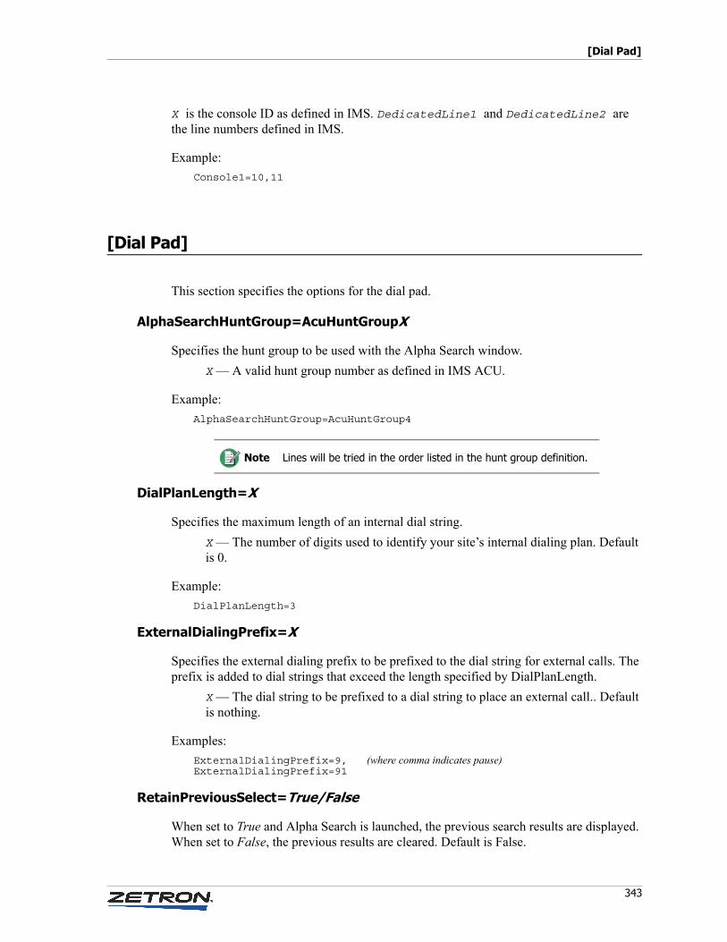
343
[Dial Pad]
X is the console ID as defined in IMS. DedicatedLine1 and DedicatedLine2 are the line numbers defined in IMS.
Example:
Console1=10,11
[Dial Pad]
This section specifies the options for the dial pad.
AlphaSearchHuntGroup=AcuHuntGroupX
Specifies the hunt group to be used with the Alpha Search window.
X — A valid hunt group number as defined in IMS ACU.
Example:
AlphaSearchHuntGroup=AcuHuntGroup4
DialPlanLength=X
Specifies the maximum length of an internal dial string.
X — The number of digits used to identify your site’s internal dialing plan. Default is 0.
Example:
DialPlanLength=3
ExternalDialingPrefix=X
Specifies the external dialing prefix to be prefixed to the dial string for external calls. The prefix is added to dial strings that exceed the length specified by DialPlanLength.
X — The dial string to be prefixed to a dial string to place an external call.. Default is nothing.
Examples:
ExternalDialingPrefix=9, (where comma indicates pause)ExternalDialingPrefix=91
RetainPreviousSelect=True/False
When set to True and Alpha Search is launched, the previous search results are displayed. When set to False, the previous results are cleared. Default is False.
Note Lines will be tried in the order listed in the hunt group definition.
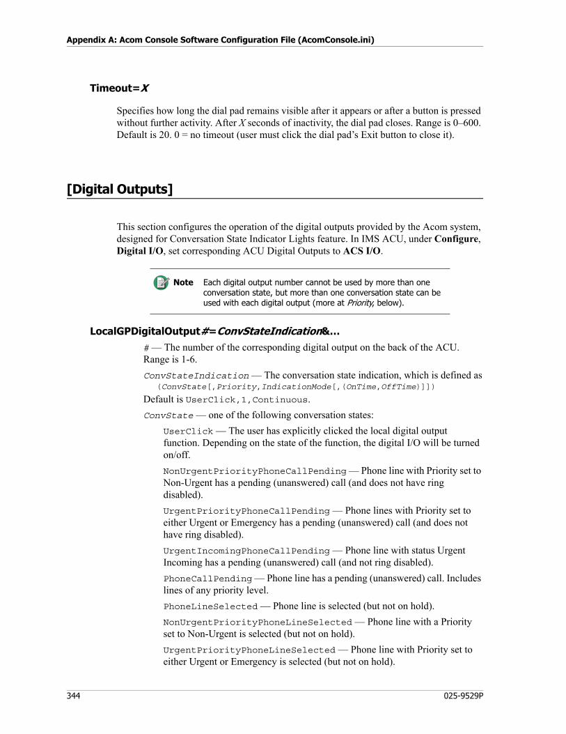
Appendix A: Acom Console Software Configuration File (AcomConsole.ini)
344 025-9529P
Timeout=X
Specifies how long the dial pad remains visible after it appears or after a button is pressed without further activity. After X seconds of inactivity, the dial pad closes. Range is 0–600. Default is 20. 0 = no timeout (user must click the dial pad’s Exit button to close it).
[Digital Outputs]
This section configures the operation of the digital outputs provided by the Acom system, designed for Conversation State Indicator Lights feature. In IMS ACU, under Configure, Digital I/O, set corresponding ACU Digital Outputs to ACS I/O.
LocalGPDigitalOutput#=ConvStateIndication&…# — The number of the corresponding digital output on the back of the ACU. Range is 1-6.
ConvStateIndication — The conversation state indication, which is defined as(ConvState[,Priority,IndicationMode[,(OnTime,OffTime)]])
Default is UserClick,1,Continuous.
ConvState — one of the following conversation states:
UserClick — The user has explicitly clicked the local digital output function. Depending on the state of the function, the digital I/O will be turned on/off.
NonUrgentPriorityPhoneCallPending — Phone line with Priority set to Non-Urgent has a pending (unanswered) call (and does not have ring disabled).
UrgentPriorityPhoneCallPending — Phone lines with Priority set to either Urgent or Emergency has a pending (unanswered) call (and does not have ring disabled).
UrgentIncomingPhoneCallPending — Phone line with status Urgent Incoming has a pending (unanswered) call (and not ring disabled).
PhoneCallPending — Phone line has a pending (unanswered) call. Includes lines of any priority level.
PhoneLineSelected — Phone line is selected (but not on hold).
NonUrgentPriorityPhoneLineSelected — Phone line with a Priority set to Non-Urgent is selected (but not on hold).
UrgentPriorityPhoneLineSelected — Phone line with Priority set to either Urgent or Emergency is selected (but not on hold).
Note Each digital output number cannot be used by more than one conversation state, but more than one conversation state can be used with each digital output (more at Priority, below).
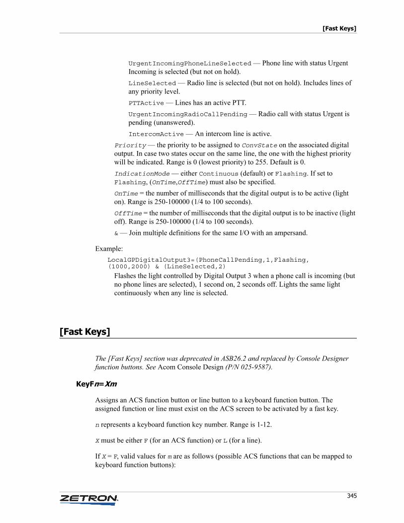
345
[Fast Keys]
UrgentIncomingPhoneLineSelected — Phone line with status Urgent Incoming is selected (but not on hold).
LineSelected — Radio line is selected (but not on hold). Includes lines of any priority level.
PTTActive — Lines has an active PTT.
UrgentIncomingRadioCallPending — Radio call with status Urgent is pending (unanswered).
IntercomActive — An intercom line is active.
Priority — the priority to be assigned to ConvState on the associated digital output. In case two states occur on the same line, the one with the highest priority will be indicated. Range is 0 (lowest priority) to 255. Default is 0.
IndicationMode — either Continuous (default) or Flashing. If set to Flashing, (OnTime,OffTime) must also be specified.
OnTime = the number of milliseconds that the digital output is to be active (light on). Range is 250-100000 (1/4 to 100 seconds).
OffTime = the number of milliseconds that the digital output is to be inactive (light off). Range is 250-100000 (1/4 to 100 seconds).
& — Join multiple definitions for the same I/O with an ampersand.
Example:
LocalGPDigitalOutput3=(PhoneCallPending,1,Flashing,(1000,2000) & (LineSelected,2)
Flashes the light controlled by Digital Output 3 when a phone call is incoming (but no phone lines are selected), 1 second on, 2 seconds off. Lights the same light continuously when any line is selected.
[Fast Keys]
The [Fast Keys] section was deprecated in ASB26.2 and replaced by Console Designer function buttons. See Acom Console Design (P/N 025-9587).
KeyFn=Xm
Assigns an ACS function button or line button to a keyboard function button. The assigned function or line must exist on the ACS screen to be activated by a fast key.
n represents a keyboard function key number. Range is 1-12.
X must be either F (for an ACS function) or L (for a line).
If X = F, valid values for m are as follows (possible ACS functions that can be mapped to keyboard function buttons):
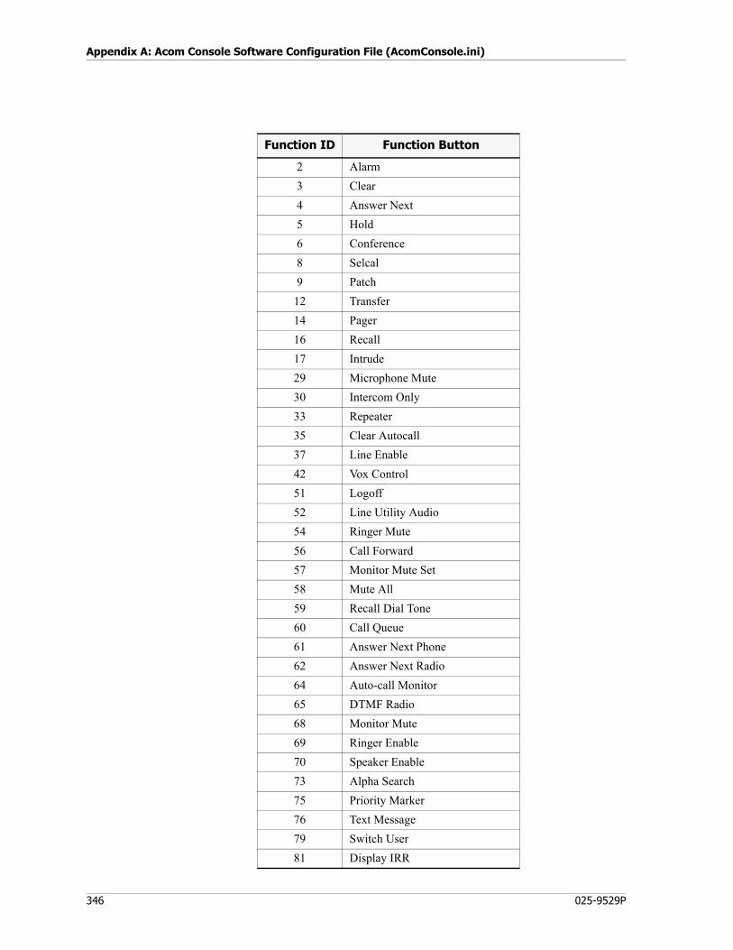
Appendix A: Acom Console Software Configuration File (AcomConsole.ini)
346 025-9529P
Function ID Function Button
2 Alarm
3 Clear
4 Answer Next
5 Hold
6 Conference
8 Selcal
9 Patch
12 Transfer
14 Pager
16 Recall
17 Intrude
29 Microphone Mute
30 Intercom Only
33 Repeater
35 Clear Autocall
37 Line Enable
42 Vox Control
51 Logoff
52 Line Utility Audio
54 Ringer Mute
56 Call Forward
57 Monitor Mute Set
58 Mute All
59 Recall Dial Tone
60 Call Queue
61 Answer Next Phone
62 Answer Next Radio
64 Auto-call Monitor
65 DTMF Radio
68 Monitor Mute
69 Ringer Enable
70 Speaker Enable
73 Alpha Search
75 Priority Marker
76 Text Message
79 Switch User
81 Display IRR
347
[GE-Star]
If X = L, valid values for m are the available line numbers.
Examples:
KeyF12=F5
assigns the Hold function to F12.KeyF9=L20
causes Line 20 to be selected when F9 is pressed.
[GE-Star]
PTTID=X[*/#]
Specifies this console’s PTT ID for use with GE-Star radios.
X — The PTT ID. Must be 5 digits long. If the actual PTT ID is only 4 digits long, use 0 as first digit here.
Append with * for portable radio, # for mobile.
Examples:
PTTID=01234*PTTID=12345#
[Incoming Call Queue]
This section pertains only to the default incoming call queue.
AllowRadioInAnswerNext=True/False
Specifies whether the Answer Next function button can be used to answer radio calls.
True — Clicking the Answer Next button answers the next call, whether it is a phone call or a radio call. Default.
False — Clicking the Answer Next button answers the next phone call.
ExcludeCallsOnRingDisabledLines=True/False
Specifies whether calls on ring-disabled lines should appear in the incoming call queue.
True — Calls incoming on lines for which ringing has been disabled will not appear in the call queue.
False — Calls incoming on lines for which ringing has been disabled will appear in the queue. Default.
Appendix A: Acom Console Software Configuration File (AcomConsole.ini)
348 025-9529P
OperationMode=X
Specifies the sort order of the call queue.
X — Sort order. Range is 1-4.
• 1 = by time
• 2 = by line priority
• 3 = by call type
• 4 = by call type, then by line priority (default)
Example:
OperationMode=1
[Incoming Calls]
IncomingCallPopup=True/False
Specifies behavior of the Incoming Call popup window.
True — When an incoming call is received on an enabled line, the Incoming Call popup window will appear in the foreground if ACS is not being displayed on top relative to other running applications. Default.
False — An incoming call will never cause the Incoming Call popup to appear.
[Initial Level]
MonitorSpeakerVolume=level
Specifies the volume level to set for Monitor Speakers 1-4 whenever a reset occurs.
level — The volume level in percentage. Range is 0-100. Default is 50.
SelectSpeakerLevel=level
Specifies the volume level to set for the Select Speaker whenever a reset occurs.
level — The volume level in percentage. Range is 0-100. Default is 50.
349
[Intercoms]
[Intercoms]
This section specifies options for the Intercom function.
AllowIntercomsDuringPhoneCall=True
Specifies whether the Operator is allowed to be on an Intercom call and a Phone call at the same time.
True = Allow Intercoms during Phone call. Default.
False = Do not allow Intercoms during Phone call.
ShowAnnounce=True/False
This setting was deprecated in ASB29 and replaced by Allow Announce in Acom Profile Management.
Specifies whether the Announce button appears in the Console Selection window used for making Intercom calls.
True — The button is visible in the window.
False — The button is hidden. Default.
ShowBroadcast=True/False
This setting was deprecated in ASB29 and replaced by Allow Broadcast in Acom Profile Management.
Specifies whether the Broadcast button appears in the Console Selection window used for making Intercom calls.
True — The button is visible in the window.
False — The button is hidden. Default.
SingleAutoConnectOnly=True/False
Specifies whether one or more autoconnect intercom calls are allowed.
True — Only one autoconnect intercom call is allowed.
False — All intercom calls can be autoconnect. Default.
[Interfaces]
This sections defines options for the audio interfaces.
Appendix A: Acom Console Software Configuration File (AcomConsole.ini)
350 025-9529P
AudioPanelLocation=interface
Specifies the speaker interface to which the Audio Panel audio is directed. Valid values for interface are as follows. No default.
AP_Main — Audio is routed to the Audio Panel Speaker.
HS_Main — Audio is routed to the Handset.
HS_Spkr — Audio is routed to the Handset Speaker.
Mon1_Spkr — Audio is routed to the Monitor 1 Speaker.
Mon2_Spkr — Audio is routed to the Monitor 2 Speaker.
HandsetLocation=interface
Specifies the speaker interface to which the handset audio is directed. Valid values for interface are as follows. No default.
AP_Main — Audio is routed to the Audio Panel Speaker.
HS_Main — Audio is routed to the Handset.
HS_Spkr — Audio is routed to the Handset Speaker.
Mon1_Spkr — Audio is routed to the Monitor 1 Speaker.
Mon2_Spkr — Audio is routed to the Monitor 2 Speaker.
HandsetOnly=True/False
This setting was deprecated in ASB25.4 and replaced by SplitRadioPhoneAudio.
Specifies whether all of the audio is forced to the Handset interface.
True — Audio Panel and Headset audio will be routed to the Handset interface.
False — Normal operation. Default.
PhonePriority=True/False
This setting was deprecated in ASB25.4 and replaced by SplitRadioPhoneAudio.
Specifies whether phone lines have priority over radio lines on the Handset interface.
True — Selecting a phone line forces any radio lines from the Handset interface to the Audio Panel interface. Radio lines are put back on the Handset interface when the phone line is cleared.
False — Selecting a phone line does not have any affect on the interface used for radio lines. Default.
PreferredInterface=Phone/Radio
This setting was deprecated in ASB25.4 and replaced by SplitRadioPhoneAudio.
351
[Interfaces]
Specifies whether to split phone and radio audio or use the standard audio routing configuration. This option will only be considered when HandsetOnly=True and PhonePriority=False are set.
Phone — Split phone and radio. If a phone line is active, move radio line audio to audio panel.
Radio — Use standard audio routing. Default.
SplitRadioPhoneAudio=True/False
This setting was deprecated in ASB29 and replaced by Select Audio Default Routing Mode = “Dynamic Split” in Acom Profile Management.
Specifies whether Radios, Phones and Intercoms will be mixed on the Handset interface, or split between the Handset and Audio Panel interfaces.
True — Radios are selected on the Handset interface when no Phones or Intercoms are active. Selecting a Phone or Intercom moves all Radios to the Audio Panel interface. Once all Phones and Intercoms are cleared or placed on Hold, then Radios are moved back to the Handset interface.
False — Radios, Phones, and Intercoms are always mixed on the Handset interface. Default.
EnablePCTonesToMonSpk1=True/False
Specifies whether the standard tones generated by the PC will be redirected to the Monitor Speaker 1 (MS1) audio interface.
True — PC tones will be redirected to this interface. Default.
False — PC tones will not be redirected to this interface.
EnablePCTonesToMonSpk2=True/False
Specifies whether the standard tones generated by the PC will be redirected to the Monitor Speaker 2 (MS2) audio interface.
True — PC tones will be redirected to this interface.
False — PC tones will not be redirected to this interface. Default.
EnablePCTonesToMonSpk3=True/False
Specifies whether the standard tones generated by the PC will be redirected to the Monitor Speaker 3 (MS3) audio interface.
True — PC tones will be redirected to this interface.
False — PC tones will not be redirected to this interface. Default.
EnablePCTonesToMonSpk4=True/False
Specifies whether the standard tones generated by the PC will be redirected to the Monitor Speaker 4 (MS4) audio interface.
Appendix A: Acom Console Software Configuration File (AcomConsole.ini)
352 025-9529P
True — PC tones will be redirected to this interface.
False — PC tones will not be redirected to this interface. Default.
EnablePCTonesToHandset=True/False
Specifies whether the standard tones generated by the PC will be redirected to the Handset (HS) audio interface.
True — PC tones will be redirected to this interface.
False — PC tones will not be redirected to this interface. Default.
EnablePCTonesToAudioPanel=True/False
Specifies whether the standard tones generated by the PC will be redirected to the Audio Panel (AP) audio interface.
True — PC tones will be redirected to this interface.
False — PC tones will not be redirected to this interface. Default.
EnablePCTonesToMonSpk1=True/False
Specifies whether the standard tones generated by the PC will be redirected to the Monitor Speaker 1 (MS1) audio interface.
True — PC tones will be redirected to this interface. Default.
False — PC tones will not be redirected to this interface.
EnablePCTonesToMonSpk2=True/False
Specifies whether the standard tones generated by the PC will be redirected to the Monitor Speaker 2 (MS2) audio interface.
True — PC tones will be redirected to this interface.
False — PC tones will not be redirected to this interface. Default.
EnablePCTonesToMonSpk3=True/False
Specifies whether the standard tones generated by the PC will be redirected to the Monitor Speaker 3 (MS3) audio interface.
True — PC tones will be redirected to this interface.
False — PC tones will not be redirected to this interface. Default.
EnablePCTonesToMonSpk4=True/False
Specifies whether the standard tones generated by the PC will be redirected to the Monitor Speaker 4 (MS4) audio interface.
True — PC tones will be redirected to this interface.
False — PC tones will not be redirected to this interface. Default.
353
[IRR]
EnablePCTonesToHandset=True/False
Specifies whether the standard tones generated by the PC will be redirected to the Handset (HS) audio interface.
True — PC tones will be redirected to this interface.
False — PC tones will not be redirected to this interface. Default.
EnablePCTonesToAudioPanel=True/False
Specifies whether the standard tones generated by the PC will be redirected to the Audio Panel (AP) audio interface.
True — PC tones will be redirected to this interface.
False — PC tones will not be redirected to this interface. Default.
[IRR]
EnableIRR=True/False
Specifies whether the Integrator Install Recall Recorder application should be accessible from ACS.
True — IRR is enabled.
False — IRR is disabled. Default.
If IRR is enabled, but UMS is disabled (see EnableUMS, below), it is also necessary to execute the .reg file that is in the IRR folder on the distribution CD.
EnableIRRSoftwareControl=True/False
Specifies whether Integrator IRR is to use software-controlled recording. If not enabled, ACS will expect IRR recording to be controlled by way of contact closure or VOX. This entry is only valid if EnableIRR is set to True.
True — Instructs Integrator IRR to use software controlled recording.
False — Software-controlled recording is disabled. Default.
IRRChannelAlias=text
Specifies the IRR audio channel to use during software-controlled recording.
text — Must match the Source Alias defined in Integrator IRR for the recording channel to be used. No default. This entry is only valid if both EnableIRR and EnableIRRSoftwareControlTrue are set to True. See also Source Alias in the Integrator IRR Product Manual.
Appendix A: Acom Console Software Configuration File (AcomConsole.ini)
354 025-9529P
[Line Groups]
This section defines groups of lines by name, so that the names can be used in line lists in place of or in addition to line numbers.
Name=LinelistName — An alias for the line group. Can be any string. Hunt groups defined in IMS ACU are automatically read in when ACS starts up, and they are merged with these Name entries.
Linelist — Comma-separated list of line numbers. An uninterrupted series can be hyphenated. Hunt groups defined in IMS ACU can also be referenced, by using the term AcuHuntGroupX, where the range of X is 1-8.
Examples:
fire=1,3,5police=2,4,6-10,15,20-25rescue=90-99HG1=AcuHuntGroup1HG2=AcuHuntGroup2,AcuHuntGroup3
[Line Selection]
This section defines options that affect line selection behavior.
ClearButtonMode=X
Specifies the line types on which the Clear button will operate. Range is 0-2.
0 — All lines can be cleared. Default.
1 — Only phone lines can be cleared.
2 — Only radio lines can be cleared.
HoldFunctionality=X
Specifies the action of the hold button. Range is 0-1.
0 — If one line is selected, clicking Hold puts the line on hold. If multiple lines are selected, the operator must click Hold, then click the line to be put on hold. The Hold button cannot be used to take lines off hold. Default.
Note For hunt groups, lines will be tried in the order listed in the hunt group definition.
355
[Line Selection]
1 — Lines are put on hold by clicking Hold, then clicking the line to be put on hold. If one or more lines are on hold, and there are no other selected lines, clicking the Hold button takes the longest held call off hold.
HoldPriority=X
Specifies the line priority number that is not allowed to be put on hold. For example, if HoldPriority is set to 2, only lines with a priority of 0 or 1 can be put on hold. There is no set range; priorities are merely relative to each other. Default is lines of any priority level can be placed on hold.
PreventLineIntrude=True/False
Specifies whether the operator can perform an intrude on lines handled by other operators.
True — Prevents intrude on lines.
False — Allows intrude on lines. Default.
PreventPhoneMonitor=True/False
Specifies whether the operator can monitor phone lines handled by other operators.
True — Prevents phone lines from being monitored.
False — Allows phone lines to be monitored. Default.
PreventRadioLineTransfer=True/False
Specifies whether the operator can transfer a radio line.
True — Radio lines cannot be transferred.
False — Radio lines can be transferred. Default.
ResetVolumeOnSelect=True/False
Specifies whether the select audio volume will be reset when a radio or phone line is selected.
True — Select audio volume will be reset to the value specified by the InitialLevel option in the [Line Volume] section whenever a line is selected (either directly or indirectly). See also InitialLevel=X on page 356.
False — Select audio volume will remain at the user-defined setting at all times. Default.
ReverseGroupSelect=True/False
Specifies the behavior when a group button is deselected.
True — Only the buttons selected using the group select are unselected when the group button is deselected.
False — All buttons in the group are deselected when the group button is deselected. Default.
Appendix A: Acom Console Software Configuration File (AcomConsole.ini)
356 025-9529P
[Line Volume]
This section specifies some default line volume settings.
BoostLevel=X
Specifies the level to which to boost the volume when the Volume Boost or Group Volume Boost function is activated. X is the negative of the level, in dB. Range is 0-40. Default is 0.
Examples:
BoostLevel=40 (level is -40 dB, the lowest level)BoostLevel=0 (level is 0 dB, the highest level)
InitialLevel=X
Specifies the initial volume level for all lines upon console reset. X is the negative of the level, in dB. Range is 0-40. Default is 20.
Examples:
InitialLevel=40 (level is -40 dB, the lowest levelInitialLevel=0 (level is 0 dB, the highest level
InitialMonitorLevel=X
Specifies the initial monitor (unselect) level for all radio and phone lines upon reset. X is the negative of the level, in dB. Range is 0-40. Default is 0.
Examples:
InitialMonitorLevel=40 (level is -40 dB, the lowest level)InitialMonitorLevel=0 (level is 0 dB, the highest level)
[Local Digital Inputs]
LocalGPDigitalInputX=Function
Can be used to specify functions associated with digital inputs provided by the Acom system.
Note Also, if ResetVolumeOnSelect is set to True in the [Line Selection] section, selecting a radio or phone line will reset the line volume to the value specified by InitialLevel. See ResetVolumeOnSelect=True/False on page 355.
357
[Local Digital Outputs]
X — Number of the corresponding ACU Digital Input in IMS, which must be set to ACS I/O.
Function — One of the following:
• AnswerNext (to support the Answer Next function button)
• SquelchDisable (to support the Squelch Disable function button)
• InstantTx (to support instant Tx by way of the foot switch)
• PTT1
• MuteRadiosInSelectXInterface (where X = Interface number)(to support the Mute Radios function button)
• AlertToneX (where X = Alert Tone ID)
Examples:
LocalGPDigitalInput1=AnswerNextLocalGPDigitalInput2=SquelchDisableLocalGPDigitalInput3=InstantTxLocalGPDigitalInput4=PTTLocalGPDigitalInput5=MuteRadiosInSelect1InterfaceLocalGPDigitalInput6=AlertTone1
1 The PTT setting will key the console using general PTT when active. An ACU digital input (input 6 for example) would map to LocalGPDigitalInput6=PTT and would cause the console to key up. If you do not designate any lines as Station Turn Out (STO) then it just acts like an external PTT. If there is a selected STO line on the console, it will be keyed and not the other lines.
[Local Digital Outputs]
BlinkRate=X
If using Local Digital Output function key, this specifies the flash rate.
X — Number of milliseconds the light will be on. The same value is used for the time the light will be off.
Example:
BlinkRate=1000
Appendix A: Acom Console Software Configuration File (AcomConsole.ini)
358 025-9529P
[MDC]
AutoClearLastCallInfo=True/False
This setting was deprecated in ASB27 and replaced by ANIPersistence.
Specifies whether the non-emergency MDC PTT ID is cleared automatically from a line button after 10 seconds if no new calls arrive within that timeout period.
True — The PTT ID is cleared after the 10-second timeout period. Default.
False — The PTT ID is kept until the next one replaces it.
CallHistoryFilter=option
Specifies whether the list of calls in the MDC-1200 Call History window will be filtered, instead of displaying all incoming calls.
All — Incoming calls on any line display. Default.
MonitoredOnly — Only incoming calls on Monitored lines display.
SelectedOnly — Only incoming calls on Selected lines display.
SelectedOrMonitoredOnly — Only incoming calls on Selected or Monitored lines display.
MomentarySelectiveCall=True/False
Specifies whether an MDC selective call is momentary or persistent across multiple PTTs.
True — A selective call will be sent once prior to the first PTT.
False — A selective call will be sent with each PTT. Default.
StatusTextX=text
Specifies text for MDC status messages, which can be used in the MDC dial pad display.
X = number for the StatusText entry. Range is 1-255 (up to 255 entries are allowed).
Text = text for the StatusText entry.
Examples:
StatusText1=Dialing error.StatusText2=No answer.StatusText3=BusyStatusText4=Lunch breakStatusText5=MeetingStatusText6=Can't answer
359
[Monitor]
[Monitor]
DefaultMuteLevel=X
Specifies the initial mute level for all radio lines upon restarting ACS. Applies to Mute All and Monitor Mute functions. X is the negative of the level, in dB. Range is 0-40. No default.
Examples:
DefaultMuteLevel=40 (level is -40 dB, the lowest level)DefaultMuteLevel=0 (level is 0 dB, the highest level)
[Mouse]
TrackMovement=True/False
Specifies whether a button is highlighted when the mouse pointer is positioned over it. If set to True, the highlight is achieved using a frame near the borders of the button.
True — Button under mouse pointer is highlighted.
False — Button is not highlighted. Default.
[Paging]
This section specifies settings necessary for paging.
ClearCompletedStack=True/False
Specifies whether the paging stack is cleared of all successful pages at the end of transmission.
True — The paging stack is cleared of all successful pages when paging is completed. Pages with at least one failed line remain on the stack until manually cleared. Default.
False — The paging stack remains unchanged until manually cleared. Resending the pages will still only repage new entries and ones in which the page previously failed.
Appendix A: Acom Console Software Configuration File (AcomConsole.ini)
360 025-9529P
Filename=filename
Specifies the name of the paging activity log file. The console ID is prepended to the file name to support network logging, and a .log extension is appended. Default is PagingActivity.
The default folder for log files is C:\Program Files\Zetron\AcomConsole\Logs.
This path can be changed by including it in the filename.
This parameter is useful only if LogPagingActivity is set to True (see LogPagingActivity=True/False on page 360).
Examples:
Filename=PageLogs
would cause the file PageLogs.log to be maintained inC:\Program Files\Zetron\AcomConsole\Paging
Filename=C:\Program Files\Zetron\Acom\Pages\Log
would cause the file Log.log to be maintained in C:\Program Files\Zetron\Acom\Pages
LogPagingActivity=True/False
Specifies whether paging activity on the console is logged. If set to True, the following items are recorded: Time, Date, User Name, Console Number, and Capcode. Log files are plain ASCII text files and store two weeks of data.
PlayTones=condition
Specifies whether and where paging tones are played back to the operator. For paging tones that are played back to the console operator, the Paging Loopback Gain setting in IMS ALS determines the attenuation. Condition must be one of the following:
AlwaysOnSelectInterface — Paging tones are always played back to the console operator, through the Select audio interface.
FollowsLineState = Paging tones are always played back to the console operator, through either the Select audio interface or the Monitor audio interface, depending on the state of the line over which the page is being sent. Default.
Never — Paging tones are never played back.
SafetyMode=True/False
Specifies whether pages are sent immediately as sent to the stack or delayed until Send is pressed.
True — Forces all pages to stack and not be sent until the Send button is pressed. Default.
False — Pages are added to the stack and sent immediately. Also uses the Pager line button's Stack Entry=Enabled/Disabled setting in Acom Console Designer.
361
[Ports]
VoiceHoldTime=XSpecifies the number of seconds to apply carrier following the transmission of paging tones and preceding voice transmission. Range is 0-60. A value of 0 disables the ability to set Voice Hold Time in the Paging Configuration utility (see Lines to Select at End of Page on page 322). Default is 0.
[Ports]
This section specifies the ports used by the console’s various IP-based services.
port — The port number used to host the service.
CAD=port
A phone call can be dialed from the console through an associated CAD terminal. May work with any type of phone line, but only PSTN lines are officially supported. Default port on which the CAD interface is hosted is 22025.
Debug=port
Default port on which the remote debugging interface is hosted is 22023.
Web=port
Default port on which the web interface is hosted is 22024. Access is by way of a standard web browser. For example, http://localhost:22024 will access the information about the local console.
[Queue Box]
This section is used to configure certain behaviors related to the Enhanced Radio Queue (ERQ), which can be used to display received Selcals directed to one or more specific operator roles or console positions.
AllowSwitchCallRemovals=True/False
Specifies whether Selcals are removed from the ERQ automatically, based on IMS configuration.
True — Selcals are removed from the ERQ as the Acom switch indicates to do so.
False — Selcals are not removed automatically. Default.
Appendix A: Acom Console Software Configuration File (AcomConsole.ini)
362 025-9529P
CallHistoryFilter=option
Specifies whether the list of calls in the ERQ Call History window will be filtered, instead of displaying all incoming calls.
All — Incoming calls on any line display. Default.
MonitoredOnly — Only incoming calls on Monitored lines display.
SelectedOnly — Only incoming calls on Selected lines display.
SelectedOrMonitoredOnly — Only incoming calls on Selected or Monitored lines display.
DisplayMatchingSelcalOnly=True/False
Specifies whether any or only matching Selcals are displayed in the ERQ.
True — Only matching Selcals are displayed.
False — All Selcals are displayed. Default.
RemoveEntryOnSelection=False
This allows for Selcals from the same source to different consoles to be removed from all console queues when selected by one console
True — Removes selcals from all queues when selected by one console
False — Removes selcals from console queue at which it was selected. Default.
Additional Configuration of the ERQ
Each radio line may have several mobile radios with unique Selcal numbers. To assist the console operator in identifying the radio line a call has originated from, the entries in the ERQ may be color-coded. This color coding is configured in an XML file named RadioQueueColorScheme.xml in the AcomConsole folder. In this file each radio line needs to have its own color configuration, as follows:
<RadioQueueColorScheme><Line number="1">
<PrimaryBackColor Red="0" Green="255" Blue="0"/><PrimaryTextColor Red="255" Green="255" Blue="255"/><SecondaryBackColor Red="128" Green="255" Blue="128"/><SecondaryTextColor Red="255" Green="255" Blue="255"/>
</Line><Line number="2">
<PrimaryBackColor Red="0" Green="0" Blue="255"/><PrimaryTextColor Red="0" Green="0" Blue="0"/><SecondaryBackColor Red="128" Green="128" Blue="255"/><SecondaryTextColor Red="0" Green="0" Blue="0"/>
</Line>...other Line entries...
</RadioQueueColorScheme>
number — Specifies the line number. There can be up to 400 Line entries, one for each line (but it’s not likely there will be very many unique entries).
BackColor — The color of the background of the entry in the ERQ when there is an incoming call on the specified line.
363
[Radio Lines]
TextColor — The color of the text of the entry in the ERQ when there is an incoming call on the specified line.
Red, Green, Blue — Specify the RGB value of the color.
Primary — The color used for the longest waiting Selcal in the ERQ, incoming on the specified line.
Secondary — The color used for any subsequent Selcals in the ERQ, incoming on the specified line. Typically this would be a lighter shade of the primary color.
In the example above, the ERQ entry for the longest waiting call from line 1 will have black text on a green background. ERQ entries for subsequent calls from line 1 will have black text on a light green background. The ERQ entry for the longest waiting call from line 2 will have white text on a blue background. ERQ entries for subsequent calls from line 2 will have white text on a light blue background.
When the longest waiting Selcal from a line is answered, the next longest waiting Selcal from that line assumes that line’s primary colors.
Red (Red="255" Green="0" Blue="0") cannot be used. It is reserved for emergency calls.
See also EmergencyCallStatus=list on page 367.
[Radio Lines]
This section is used to configure certain behaviors related to radio lines.
ANIPersistenceTime=X
Specifies if and when the ANI information is cleared automatically from a line button if no new calls arrive within the configurable timeout period. Default is 10.
X = Number of seconds ANI persists before it is cleared. If set to 0, the ANI is kept until the next one replaces it. Default = 10.
AudibleIncoming=line1,line2,...
Specifies which radio lines play a ring tone upon receiving an incoming call. Separate line numbers with a comma. No defaults.
Example:
AudibleIncoming=fire,11-20,99
Tip In systems where OpenSky is implemented, this option should be assigned to all OpenSky lines.
Appendix A: Acom Console Software Configuration File (AcomConsole.ini)
364 025-9529P
CDPersistenceTime=X
Specifies the length of time that the line button will remain in Incoming state after either the absence of incoming radio activity or carrier detect is detected. X is the time, in seconds. Range is 1 to 255. The setting of 255 causes the Incoming state to persist until the line is selected. Default is 3.
DisplayMonitorFunctionColor=True/False
Specifies how line buttons for monitored lines have their idle state color set.
True — If a line is monitored, as long as it is idle its line button takes on the color of the associated Monitor function button.
False — Monitor color is taken from AcomConsole.ini setting. Default. See Monitor=color on page 334.
DisplayOutgoingPTT=True/False
Specifies whether an outgoing PTT is indicated on the line button with yellow text. (The normal color change of the PTT button is not affected.) Applies only to Demo mode. In Normal mode, the yellow text always occurs.
True — Yellow text PTT indication is shown on the line button.
False — Yellow text is not shown. Default for Demo mode.
KeepPTTID=True/False
Specifies whether the PTT ID stays visible on the line button only until the console shows no activity or the transmission ends, or remains until the next PTT ID arrives to replace it.
True — PTT ID is shown on the line button until the next PTT ID arrives to replace it. This feature was implemented particularly for OpenSky lines.
False — PTT ID stays visible on the line button only until the console shows no activity or the transmission ends. Default.
ReplaceKeyCaptionWithEndPointInfo=True/False
Specifies whether the remote Radio Mobile ID should overwrite the button caption or append to it. This option only applies to P25 CSSI private calls.
True — Replaces button caption with remote Radio Mobile ID.
False — Appends remote Radio Mobile ID to button caption. Default.
ShowActivityIfNotSelected=True/False
Specifies whether Unacknowledged Activity, CD, or Parallel PTT is displayed on a radio line button when it is not selected:
False — No change to the button if Unacknowledged Activity, CD, or Parallel PTT is present.
365
[Screen Positions]
True — Display Parallel PTT by changing text color to yellow, CD by changing text color to white ( in Busy or Hold state), Unacknowledged Activity by underlining the text. Default.
This option does not override the ShowCDAsKeyColorChangeIfIdle option.
ShowCDAsKeyColorChangeIfIdle=True/False
Specifies how carrier detect is indicated when in either of the following conditions:
• The line is selected (that is, grouped or conferenced).
or
• The line is monitored and is selected on another console.
True — The button color will be changed to Incoming color when CD is present. Default.
False — The button color remains as the Idle color.
This does not override the ShowActivityIfNotSelected option.
ShowCDIfSelectedAs=option
Specifies how carrier detect is indicated when a radio line is selected.
option must be one of the following:
KeyColorChange — Indicate CD status by changing the button background color to the Incoming color. Default.
TextColorChange — Indicate CD status by changing the button text color to white.
FlashingKeyColorChange — Indicate CD status by flashing the button background color between the Default color and the Incoming color.
If a line button is designed to display alarms and to display flashing CD indication, and an alarm is present, and the line button is selected, and CD is present, the line button will flash between Selected color, Alarm color, and Incoming color.
[Screen Positions]
WindowType=left,top,width,height,Y/N
This section specifies the position and size of pop-up windows. All measurements are in pixels.
WindowType — Type of the pop-up window. Must be one of the following:
DialpadDialpadMDC
Appendix A: Acom Console Software Configuration File (AcomConsole.ini)
366 025-9529P
DialpadOpenSkyEmergencyAlertfrmPagerDialPad
left — Position of left edge of window, measured from the left edge of the screen.
top — Position of top edge of window, measured from the top edge of the screen.
width — Width of window.
height — Height of window.
Y/N — Indicates whether the window’s title bar is enabled. If set to N, the title bar is hidden, and the window cannot be moved or resized. Default is Y.
If SaveSettings is set to True in the [Console] section, and if the title bar parameter above is set to N, then if an operator moves or resizes a window, the window’s final position and size will be used in overwriting the position and size parameters of its entry here. See SaveSettings=True/False on page 339.
Examples:
DialPad=400,250,144,144,NfrmPagerDialPad=545,250,144,144
[Screens]
Specifies form files for screens that can be used throughout ACS. formfile is the filename of a .dfm file. Each formfile is a standard .dfm file created in Acom Console Designer. The file must reside in the ACS home directory.
CSSIDialpad=formfile
The CSSI dial pad screen is used for P25 CSSI radios. Note if the CSSI mobile ID is set in Profile Management then the console will not register with a RFSS and this dial pad might not function correctly along with CSSI talk group lines being disabled.
DFSIDialpad=formfile
The DFSI dial pad screen is used for P25 DFSI radios. Note if the DFSI mobile ID is set in Profile Management then the console will not register with a RFSS and this dial pad might not function correctly along with CSSI talk group lines being disabled.
This should not be enabled at the same time as CSSIDialpad. If both dialpads are enabled, then the console assumes there is a DFSI system only.
SelcallDialpad=formfile
The Selcal dial pad screen is used when no other specific dial pad is available. This occurs when the dial pad is displayed from a call queue or other source not based on a function key.
367
[Selcal]
TelephoneQuickDial=formfile
This is a custom screen for setting the quick dial keys on the right side of the dial pad. The screen size should be set to 320x380. While other sizes my work, they are not officially supported at this time.
[Selcal]
This section specifies Selcal (Selective Call) options.
BeepOnANI=True/False
Specifies whether a sound is played upon ANI acknowledge or lack of acknowledge.
True — Play a sound.
False — Play a no sound.
To specify the sounds to play, see BeepANIOk=filename.wav on page 368 and BeepANIFail=filename.wav on page 368.
EmergencyCallStatus=list
Comma-separated list of status digits that identify a Selcal call as an emergency call. Default is no list. Applies only to Enhanced Radio Queue.
Example:
EmergencyCallStatus=E,F
When a Selcal call arrives with status digit E or F, it will be identified as an emergency call.
See also SelcalEmergencyIncoming=filename.wav on page 371.
PagerTxMask=Nxxx
Specifies a number N to either prepend or append to a pager ID, enabling the operator to enter a shorter ID.
xxx represents the pager ID. It is entered literally here. That is, it’s not a variable in this parameter; it simply indicates the position of the mask relative to the pager ID, so the system will know whether to prepend or append the mask. If the pager ID is composed of more than three digits, only the first three will be used.
Examples:
PagerTxMask=77xxx
Prepends 77 to the numbers of the pager ID, enabling the operator to enter, for example, 123 instead 77123.
Appendix A: Acom Console Software Configuration File (AcomConsole.ini)
368 025-9529P
PagerTxMask=xxx999
Appends 999 to the numbers of the pager ID, enabling the operator to enter, for example, 123 instead 123999.
RxMask=X
Specifies the number of digits to remove from the beginning of any incoming Selcal ID before displaying it in the Selcal queue. Range is 0-5. Default is 0.
ShowAckANI=True/False
Specifies whether the ANI acknowledge is shown for all ANI Selcal numbers or only for defined numbers.
True — Show ACK on all Selcal ANI numbers.
False — Show ACK only on defined Selcal ANI numbers. Default.
ShowLinename=True/False
Specifies whether the Line Name (Line button Text) of the received Selcal is displayed in the radio queue next to the Selcal ID.
True — Displays the line name in the radio queue.
False — Does not display the line name. Default.
[Sounds]
This section specifies the sounds to be heard at the console in various operational states. The sound files must be WAVE files (.wav). The full path to each filename is not required unless the file is not in the C:\Program Files\Zetron\AcomConsole folder. There are no defaults except for AlarmWarning.
AlarmWarning=filename.wav
Specifies the .wav file to be played if there is at least one active alarm on the console. The sound is repeated for as long as the alarm condition exists. Repetitions are separated by a pause of 10 seconds. Default is the system beep emitted by the computer.
BeepANIOk=filename.wav
Specifies the .wav file to be played when the system receives a matched ANI.
BeepANIFail=filename.wav
Specifies the .wav file to be played when the system receives an unmatched ANI.
369
[Sounds]
BusyWarning=filename.wav
Specifies the .wav file to be played when a Busy message is received from the Acom system because 1) it cannot process a command sent by ACS because it is busy doing something else, or 2) an intercom call cannot be connected because the target console has no free inter-com lines.
CleanTouchScreenWarning=filename.wav
Specifies the .wav file to be played when the Clean Touch Screen gauge reaches the 80% point. The file loops until the 100% point.
DigitalIOWarning=filename.wav
Specifies the .wav file to be played when a digital input goes into an alarm state.
EmergencyAlertWarning=filename.wav
Specifies the .wav file to be played at the console when there is an emergency alarm. The file is played continuously until the alert is acknowledges.
HoldWarning=filename.wav
Specifies the .wav file to be played when a line is on Hold for more than the HoldWarning period specified in the [Timeout Periods] section (see HoldWarning=X on page 373). The sound is repeated for as long as the hold condition exists. Repetitions are separated by a pause of 15 seconds.
IntercomAutoconnect=filename.wav
Specifies the .wav file to be played for an incoming autoconnect intercom call.
MdcEmergency=filename.wav
Specifies the .wav file to be played for an incoming MDC, OpenSky, or GE-Star Emergency Alert. Default is ringin.wav. See also EmergencyAlertAudiblePeriod=X on page 373.
NotReadySound=filename.wav
Specifies the .wav file to be played when the line is in the Not Ready state.
PageComplete=filename.wav
Specifies the .wav file to be played when a page has finished transmitting, so that the console operator will know when to go ahead and speak.
Appendix A: Acom Console Software Configuration File (AcomConsole.ini)
370 025-9529P
PTTBlockedWarning=filename.wav
Specifies the .wav file to be played when PTT from the console is blocked by the Acom system.
PTTOverrideWarning=filename.wav
Specifies the .wav file to be played when PTT from the console is overridden by a console having greater priority.
RadioIncoming=filename.wav
Specifies the .wav file to be played when carrier detect is received on a radio line. The ring is played only once.
For the sound to be played, the radio line receiving the incoming call must be specified in the AudibleIncoming option in the [Radio Lines] section (see AudibleIncoming=line1,line2,... on page 363).
RingBusy=filename.wav
Specifies the .wav file to be played when a call is incoming while the console is busy (selected phone).
RingIntercomIdle=filename.wav
Specifies the .wav file to be played when an intercom call is incoming while the console is idle.
RingPhoneIdle=filename.wav
Specifies the .wav file to be played when a phone call is incoming while the console is idle (no selected phones).
RingPhoneUrgent=filename.wav
Specifies the .wav file to be played when an urgent phone or intercom call is incoming.
Note Tetra calls have an additional method for ringing. If your system includes Tetra radios, only configure one method for ringing unless you specifically want two sounds to play. The other method is configured in the <Sound> section of the CallStack.xml file; see Acom Console Design (P/N 025-9587).
Note For all Ring entries: The ring is repeated until the call is acknowledged. The pause between rings is set under [Console Ring] on page 341.
371
[Talker IDs]
RingRadioIdle=filename.wav
Specifies the .wav file to be played when a radio call is incoming while the console is idle.
RingRadioUrgent=filename.wav
Specifies the .wav file to be played when an urgent radio call is incoming.
SelcalEmergencyIncoming=filename.wav
Specifies the .wav file to be played when any incoming Selcal that has an emergency status digit is routed to a specific operator role. See also EmergencyCallStatus=list on page 367.
SelcalRoleIncoming=filename.wav
Specifies the .wav file to be played when an incoming non-emergency Selcal is routed to a specific operator role. The Selcal role is set under the Acom Profile Management.
SepacIncomingNormal=filename.wav
Specifies the .wav file to be played when an incoming normal Sepac message is received from the Acom system. The ring is repeated until the call is acknowledged. The pause between rings is set under [Console Ring] on page 341.
SepacIncomingUrgent=filename.wav
Specifies the .wav file to be played when an incoming urgent Sepac message is received from the Acom system. The ring is repeated until the call is acknowledged. The pause between rings is set under [Console Ring] on page 341.
TxClearVoiceWarning=filename.wav
This sound indicates that clear voice (non-encrypted) is being transmitted on the first PTT. This will only sound once for a call. When the line(s) are deselected and selected again the sound will occur again on the first PTT.
[Talker IDs]
The section pertains to OpenSky and P25 logon.
P25=True/False
Specifies whether logon to a P25 network is required.
Appendix A: Acom Console Software Configuration File (AcomConsole.ini)
372 025-9529P
TalkerIDrequired=True/False
Specifies whether logon to the OpenSky network is required.
[Telephone Lines]
AnswerLongString=text
Specifies a long version of the string to be displayed in conjunction with the answering phone number. Used in the Call Queue Panel. Any ASCII text string is valid. Default is Number Called.
AnswerShortString=text
Specifies a short version of the string to be displayed in conjunction with the answering phone number. Used as a prefix to the number on dynamic line buttons. Any ASCII text string is valid. Default is CND.
DisplayNumberOfEndPoint=Originate/Answer
Specifies which end point of a connected or established line is to be displayed on dynamic line buttons and in the call queue.
Originate — Display the originating end point phone number. Also known as CLI.
Answer — Display the answering end point phone number. Also known as CND. Default.
OriginateLongString=text
Specifies a long version of the string to be displayed in conjunction with the originating phone number. Used in the Call Queue Panel. Any ASCII text string is valid. Default is Caller's Number.
OriginateShortString=text
Specifies a short version of the string to be displayed in conjunction with the originating phone number. Used as a prefix to the number on dynamic line buttons. Any ASCII text string is valid. Default is CLI.
PABXdelay=time
Specifies the time to wait after a line is seized before dialing a preprogrammed number. Range is 500-2000, in ms. Default is 500.
373
[Timeout Periods]
ReplaceKeyCaptionWithEndPointInfo=True/False
This option applies only to static line buttons. It specifies whether the CLI/CND information (label + number) should overwrite the button label or be appended to it.
True — Replace button label with CLI/CND information.
False — Append CLI/CND information to button label. Default.
ShowDialpadForCB=True/False
Specifies whether the dial pad is automatically displayed when a ringdown line (direct 2-wire line) is selected.
True — Display dial pad.
False — Do not display dial pad. Default.
[Timeout Periods]
This section specifies the timeout periods for various operations.
AutoCallMonitorTimeOut=X
Specifies the length of time that a line is monitored, when automatic monitoring is activated on lines tagged by the AutoCall Monitor function. Applies to radio lines only. Range is 0-240, in seconds. Default is 240.
EmergencyAlertAudiblePeriod=X
Specifies the length of time, in seconds, that the .wav file associated with an incoming MDC, GE-Star, or OpenSky Emergency Alert will play unless silenced manually. Default is 10. See also MdcEmergency=filename.wav on page 369.
HoldWarning=X
Specifies the length of time that a line must be on hold before the line button starts flashing. X is the time, in seconds. Default is 30. After the specified hold time, a sound is also played, if specified by the HoldWarning option in the [Sounds] section. See also HoldWarning=filename.wav on page 369).
MuteAll=X
Specifies the length of time that monitored lines are muted, when the Mute All function is activated, after which the lines are unmuted. Range is 1-240, in seconds. Default is 30.
Appendix A: Acom Console Software Configuration File (AcomConsole.ini)
374 025-9529P
MuteRadios=X
Specifies how long the Radio lines will be muted for when the Mute Radios function is activated. After this time period, the mute will be cleared. Range is 1-300, in seconds. Default is 120.
RecallDialtone=X
Specifies the length of time that a line stays on hook, when the Recall Dial Tone button is selected. Range is 0-5000, in ms. Default is 1500.
RingerMutePeriod=X
Specifies the length of time that a line is muted, when the Ringer Mute function is activated, after which the line is unmuted. Range is 1-240, in seconds. Default is 30.
[UMS]
EnableUMS=True/False
Specifies whether the Zetron User Management System is to be used to control logon and user/role permissions.
True — UMS control is enabled. Assumes UMS is installed and running prior to ACS startup. Users will be required to log on by way of the UMS logon screen in order to start ACS.
False — UMS control is disabled, because UMS is either not installed or not running. Default.
[UMS.Screens]
role=formfile,X
Specifies the main console screen form to load on startup, according to the Role specified during logon.
role — A role defined in UMS or in the Profile Configuration utility.
formfile — The filename of the .dfm file to load. The file must reside in the ACS home directory.
Note This parameter is not checked unless ShowLogonScreen is set to True. See ShowLogonScreen=True/False on page 339.
375
[User Defined Line Groups]
• X — A Selcal role defined in IMS.
Examples:
Fire=fire.dfmPolice=police.dfmOperator1=police.dfmOperator2=fire.dfmSupervisor=SupervisorPolice.dfm,1
[User Defined Line Groups]
This section defines line groups that override rules otherwise enforced by the [Line Selection] section.
If a line belongs to more than one of these groups, the last defined group that contains the line rules the line.
The line groups are defined using the following format:
LineGroupName=<SelectionLimit=N><UnselectHolds=True/False><Lines=list>
LineGroupName — Descriptive name of a user-defined line group.
SelectionLimit — Number of lines within the group allowed to be selected at a time. Range of N is from 1 to the total number of lines listed in list.
UnselectHolds — If SelectionLimit is reached, and then an additional line is selected, this specifies whether the oldest selected line is cleared or placed on hold. True = clear; False = hold.
Lines — Specifies a comma-separated list of line numbers (IDs) to be included in the group.
Examples:
ListenInLines=<SelectionLimit=1><UnselectHolds=True><Lines=1,2,3>MyLocalGroup=<SelectionLimit=3><UnselectHolds=False><Lines=21,22,23,25,26>

Appendix A: Acom Console Software Configuration File (AcomConsole.ini)
376 025-9529P
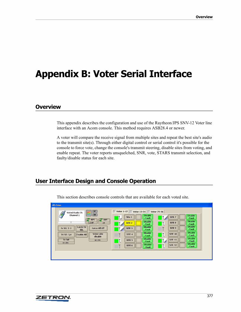
Overview
377
Appendix B: Voter Serial Interface
Overview
This appendix describes the configuration and use of the Raytheon/JPS SNV-12 Voter line interface with an Acom console. This method requires ASB28.4 or newer.
A voter will compare the receive signal from multiple sites and repeat the best site's audio to the transmit site(s). Through either digital control or serial control it's possible for the console to force vote, change the console's transmit steering, disable sites from voting, and enable repeat. The voter reports unsquelched, SNR, vote, STARS transmit selection, and faulty/disable status for each site.
User Interface Design and Console Operation
This section describes console controls that are available for each voted site.
Appendix B: Voter Serial Interface
378 025-9529P
Voted Site function button
Indications:
Active BG color shown when site is voted by the Raytheon voter. The Voted site is an enabled site with the best Signal to Noise Ration (SNR). Automatic voting occurs only if no sites are force voted.
Forced BG color shown when site is force voted either by a switch on the front of the voter or by Acom console control. Clicking the Voted Site function key in ACS will toggle the console's force vote. If either the console or switching on the voter is set forced, the site is forced.
Control:
Clicking the Voted Site function button toggles the site in/out of force voted. A forced site will be routed to the console and repeated to the transmit site(s). You may force as many sites as you wish. The Acom sends a SEL command to force vote the site.
The Voted Site function button can be set to Display-Only to prevent force vote by the console.
Voted Site Disable function button
Indications:
None. The Disabled indication is shown on the Voted Site function button
Controls:
Clicking the Voted Site Disable function button will toggle the site between disabled and enabled. A disabled site will not be automatically voted. The Acom sends a ENABLE command to the voter. The site disable is a supervisor function to remove falsing sites from vote selection.
Voted Site Force Off function button
Indications:
None.
Controls:
When clicked all sites will be unforced and the voter returned to automatic voting. The Acom sends the SEL ALL OFF command to the Raytheon voter.
379
User Interface Design and Console Operation
Voter Site Carrier Detect image control
Indications:
The Active BG image is shown when the site is unsquelched/receiving. The console gets site status updates every 500msec.
Controls:
None.
Voter Site Signal Strength gauge control
Indications:
The Active BG image is shown in 6 segments. The voter reports site SNR in values 0-31 and the Acom reduces this to 6 levels in ACS. The console gets site status updates every 500msec.
0-5=0segments
6-11=1segment
12-17=2segments
18-23=3segments
24-29=4segments
30-31=5segments (full gauge)
Controls:
None.
Voter Site Tx Select
Indications:
The Active BG color is shown when the voter selects the site for STARS transmit steering. The indication will show when the console does a momentary Tx Selection. The Tx Selection indicates what sites will key when the console uses PTT. The Forced BG color is shown when the console does a latched Tx Selection. The console gets site status updates every 500msec.
Controls:
Clicking the Voter Site Tx Select function button sets the site for momentary STARS transmit selection. When unlatched, only one site can be momentarily selected at a time. The voter will automatically clear the momentary selection after inactivity. If the Latched Voted Site Tx Select function is active, clicking this button does a latching transmit
Appendix B: Voter Serial Interface
380 025-9529P
selection and allows selecting multiple sites. The Acom sends the TXSEL or MOM_TXSEL commands to the voter.
Voter Latching Tx Select
One for all voters.
Indications:
Active BG color shown when operating in Latched mode. Clicking a Tx Select function key will toggle it on in a latched state, requiring it to be manually turned off for automatic STARS selection.
Controls:
Clicking the Latching Tx Select will toggle the function on/off. When on clicked Tx Select buttons will latch on (showing forced BG color), when the Latching Tx Select is off/idle the Tx Select buttons will show active BG color momentarily. The Acom will send MOM_TXSEL if the console is unlatched. You may not momentarily TX Sel while there are latched TX SEL sites.
Voter Site Group Tx Select
One or more for the voted line.
Indications:
Active background color when active, indicating all sites configured are transmit selected, the console will PTT these sites if the voter is keyed.
Controls:
Clicking the button should toggle the configured sites in or out of transmit selection. This button does not automatically select the voter line.
Voter Site Disable function button with no sites
This is a global key for the voter line.
Indications:
None
Controls:
When clicked it will reenable all sites. Sends ENABLE ALL ON to voter.
381
User Interface Design and Console Operation
Repeater Mode image
One image per voted line.
Indications:
Active Image shown when line in Repeat mode. The T char normally shown in the line key status region can be removed with a Console Design option. The Inactive image is shown when the line is not in repeat.
Controls:
None. See Repeater function key
Repeater function button for the line
The line must be a half-duplex radio.
Indications:
None. See repeater mode image.
Controls:
Use the Repeater function key to toggle the voted site in/out of repeat mode. The Acom will send RPT ON/OFF to the voter to cause it to repeat voted audio to STARS site(s).
Voted Site text label
This shows the voted site with the alias from the subscriber tool.
Indications:
Shows the voted site number as "SITE X" or the alias from Subscriber Manager/AEM. Only one site will be voted, it will be shown here while receiving.
Controls:
None.
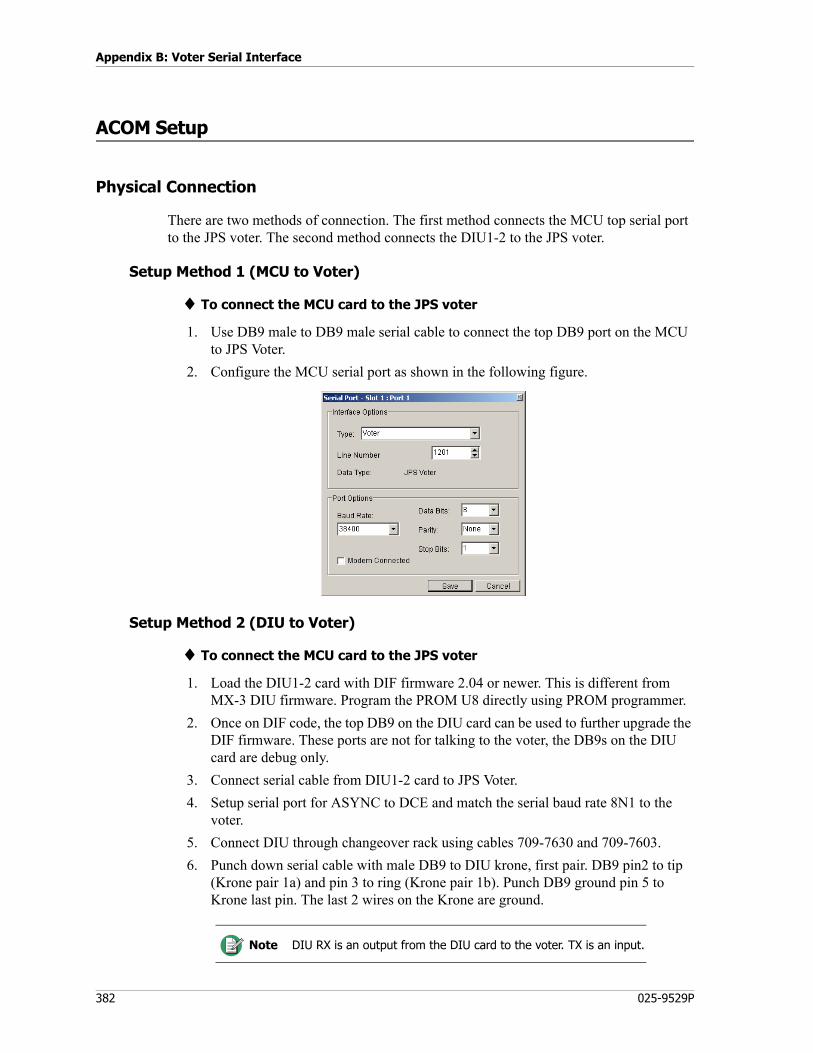
Appendix B: Voter Serial Interface
382 025-9529P
ACOM Setup
Physical Connection
There are two methods of connection. The first method connects the MCU top serial port to the JPS voter. The second method connects the DIU1-2 to the JPS voter.
Setup Method 1 (MCU to Voter)
♦ To connect the MCU card to the JPS voter
1. Use DB9 male to DB9 male serial cable to connect the top DB9 port on the MCU to JPS Voter.
2. Configure the MCU serial port as shown in the following figure.
Setup Method 2 (DIU to Voter)
♦ To connect the MCU card to the JPS voter
1. Load the DIU1-2 card with DIF firmware 2.04 or newer. This is different from MX-3 DIU firmware. Program the PROM U8 directly using PROM programmer.
2. Once on DIF code, the top DB9 on the DIU card can be used to further upgrade the DIF firmware. These ports are not for talking to the voter, the DB9s on the DIU card are debug only.
3. Connect serial cable from DIU1-2 card to JPS Voter.
4. Setup serial port for ASYNC to DCE and match the serial baud rate 8N1 to the voter.
5. Connect DIU through changeover rack using cables 709-7630 and 709-7603.
6. Punch down serial cable with male DB9 to DIU krone, first pair. DB9 pin2 to tip (Krone pair 1a) and pin 3 to ring (Krone pair 1b). Punch DB9 ground pin 5 to Krone last pin. The last 2 wires on the Krone are ground.
Note DIU RX is an output from the DIU card to the voter. TX is an input.
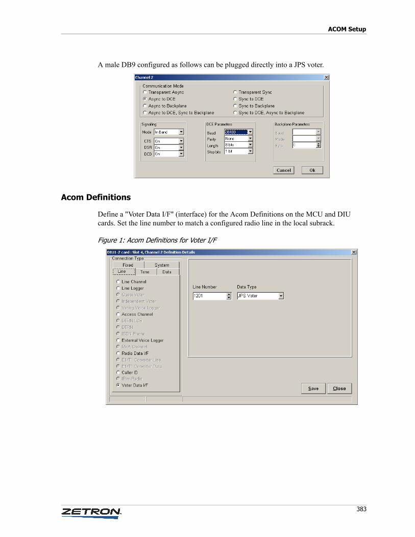
383
ACOM Setup
A male DB9 configured as follows can be plugged directly into a JPS voter.
Acom Definitions
Define a "Voter Data I/F" (interface) for the Acom Definitions on the MCU and DIU cards. Set the line number to match a configured radio line in the local subrack.
Figure 1: Acom Definitions for Voter I/F
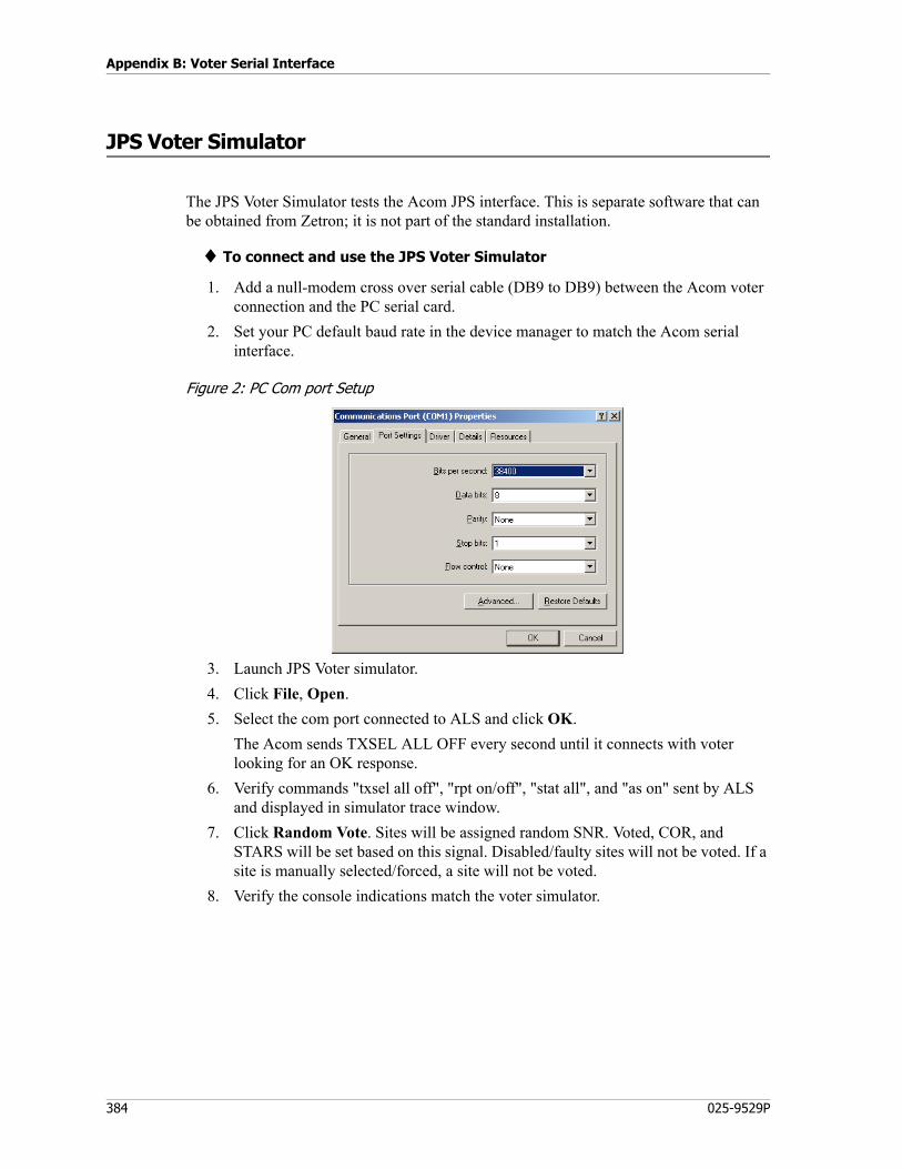
Appendix B: Voter Serial Interface
384 025-9529P
JPS Voter Simulator
The JPS Voter Simulator tests the Acom JPS interface. This is separate software that can be obtained from Zetron; it is not part of the standard installation.
♦ To connect and use the JPS Voter Simulator
1. Add a null-modem cross over serial cable (DB9 to DB9) between the Acom voter connection and the PC serial card.
2. Set your PC default baud rate in the device manager to match the Acom serial interface.
Figure 2: PC Com port Setup
3. Launch JPS Voter simulator.
4. Click File, Open.
5. Select the com port connected to ALS and click OK.
The Acom sends TXSEL ALL OFF every second until it connects with voter looking for an OK response.
6. Verify commands "txsel all off", "rpt on/off", "stat all", and "as on" sent by ALS and displayed in simulator trace window.
7. Click Random Vote. Sites will be assigned random SNR. Voted, COR, and STARS will be set based on this signal. Disabled/faulty sites will not be voted. If a site is manually selected/forced, a site will not be voted.
8. Verify the console indications match the voter simulator.
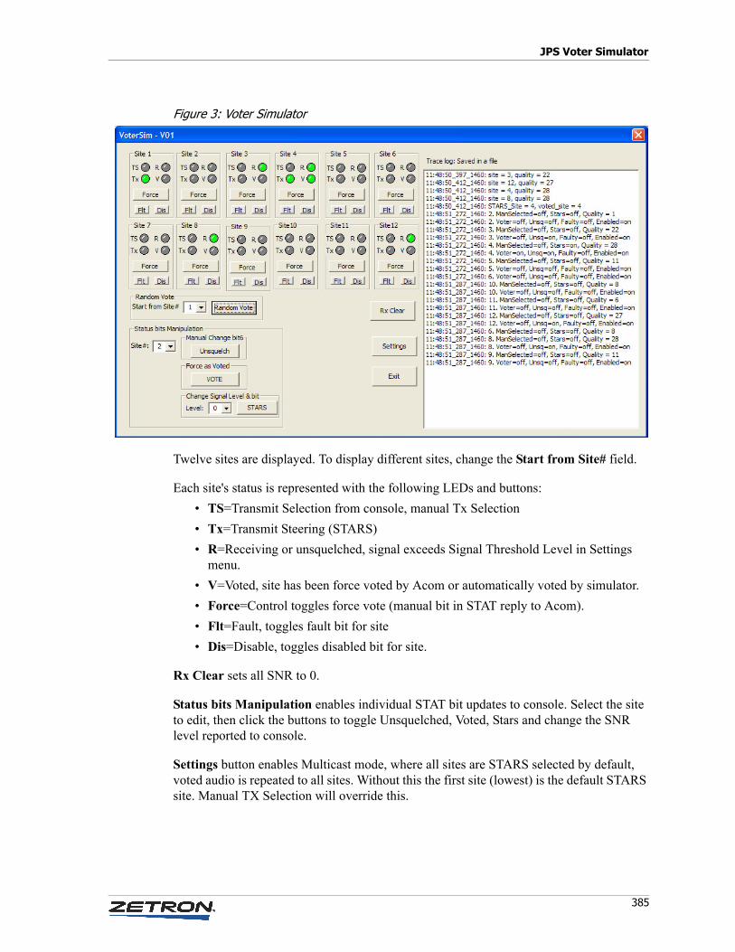
385
JPS Voter Simulator
Figure 3: Voter Simulator
Twelve sites are displayed. To display different sites, change the Start from Site# field.
Each site's status is represented with the following LEDs and buttons:
• TS=Transmit Selection from console, manual Tx Selection
• Tx=Transmit Steering (STARS)
• R=Receiving or unsquelched, signal exceeds Signal Threshold Level in Settings menu.
• V=Voted, site has been force voted by Acom or automatically voted by simulator.
• Force=Control toggles force vote (manual bit in STAT reply to Acom).
• Flt=Fault, toggles fault bit for site
• Dis=Disable, toggles disabled bit for site.
Rx Clear sets all SNR to 0.
Status bits Manipulation enables individual STAT bit updates to console. Select the site to edit, then click the buttons to toggle Unsquelched, Voted, Stars and change the SNR level reported to console.
Settings button enables Multicast mode, where all sites are STARS selected by default, voted audio is repeated to all sites. Without this the first site (lowest) is the default STARS site. Manual TX Selection will override this.
Appendix B: Voter Serial Interface
386 025-9529P
Troubleshooting
Debug Commands
DIU1-2
The DIU1-2 outputs CSPY if its powered up with serial cable attached. To watch serial communication in ASCII, type:
ADSPY [1-6]
MCU (ALS)
For help, type:
voter ?
To show high level status for all enabled voters, type:
voter s
To show site details, type the following, where “l” is the line number:
voter s l
To debug specific lines and sites, type the following, where “1” is the line number and “aa bb ...” are the sites.
voter d l aa bb ...
For example, if you want to debug voter on line 1 and only sites 1-4, type:
voter d 1 0f
To turn off, type:
voter d 0
To show line status including voter bits, type:
ACLINE x
To show voter communication, type:
Test 15 40
PC
Connect a dumb terminal into ALS serial output and verify "TXSEL ALL OFF" is sent once per second for voter line. The voter simulator generally shows you this info but you might find value in a dumb terminal monitoring the Acom output.
Caution! Test bit “0x40” is ok, but “0x20” is to be used with caution as it will display all rx data from all voter interfaces and can reset card.
!
387
Troubleshooting
ADS
"Line x" on the ACTIVE ADS will show up-to-date voter status. The inactive ADS information is stale/ignored.
Fault Logs
Look for these entries indicating that serial communication has failed.
0MCU 10:12:11 29/Apr/2011 Input Alarm (Active) : Line Alarm0MCU 10:16:14 29/Apr/2011 Line 1201 Data Connection Fault0MCU 10:16:14 29/Apr/2011 Lines Data Connection Fault
Line alarm is reported to console, notifying supervisor and possibly flashing line key button yellow.

Appendix B: Voter Serial Interface
388 025-9529P
Overview
389
Appendix C: Distributing Console Files
In this appendix:
• Installation on page 390
• The User Interface on page 392
• Setting Up and Using ZFD on page 401
• The Configuration File on page 406
Overview
This chapter describes the Zetron File Distributor application (ZFD). ZFD enables you to distribute necessary configuration files to PCs being used as Acom consoles.
Unlike the previous software used to accomplish the same sort of system maintenance (CFDS), ZFD is not a client-server application, and it does not involve any software being installed on any of the console PCs.
ZFD will be installed on a maintenance PC so that configuration files and various databases can be maintained centrally and distributed to the consoles when needed. If you need to make any changes to a configuration file or database, do it on the maintenance PC, then distribute the changed file(s) to the appropriate console(s). The maintenance PC and all of the console PCs must be on the same subnet or be using DNS, or all the console names can be defined in an LMHOSTS file.
When ZFD is running and instructed to Copy Files, it looks in a specified directory on the PC it is running on for a specified list of files and copies those files into a specified destination directory on each of the console PCs it was told to update. This mode of operation dictates certain requirements for setting up and using ZFD.
• While ZFD does not need to be installed on a console PC (in fact, it should not be), it does need to be installed on a PC that can reach each console PC by way of the network, using the network name of each console.
Appendix C: Distributing Console Files
390 025-9529P
• The path to the target directory must be the same on each console PC. To reach the target directory on each machine, ZFD combines the computer name (the name by which it is known to Windows) of the console PC with the path string recorded in the configuration file.
• The target directory on each console PC must have the sharing attribute enabled under Properties. This is necessary to allow ZFD to write files to, and delete files from the target folder on each of the console PCs.
Installation
ZFD is installed as part of the Administrative Tools software package. See Administrative Tools on page 297.
Initial Startup
The default FileDistributor.xml file will point to the folder locations suggested in this manual but it will not contain the names of any of the console PCs on your system. The first time you run the program the Main window will open so that the consoles can be defined. The following procedure will lead you through setting the paths used by ZFD and the console names for the first time.
♦ Setting ZFD parameters during the first start up:
1. Use the desktop shortcut to start ZFD. Alternatively, open the Start menu and use the RUN command to start the program. If you used the suggested paths when installing the program, the entry in the RUN command will be:C:\Program Files\Zetron\File_Distributor\FileDistributor.exe
2. Click the Add Consoles button in the upper right corner of the Main window. The Select Consoles window opens.
3. Use the options provided in the Select Consoles window to populate the list of consoles to be supported by this installation of ZFD. If you know the names of the console PCs you can type them into the field at the top of the window one-at-a-time and click the Add button. ZFD will ping that name on the network and if it fails will display a message to confirm if the console is to be added. If the console is added, the name is appended to the list on the right. You can also use the tools in the lower left to search the network for PC names and then add names from that list to the list on the right.
4. Save the changes to the consoles list and close the Select Consoles window by clicking the Save button. The new consoles will now appear in the Selected Consoles column on the far right of the Main window.
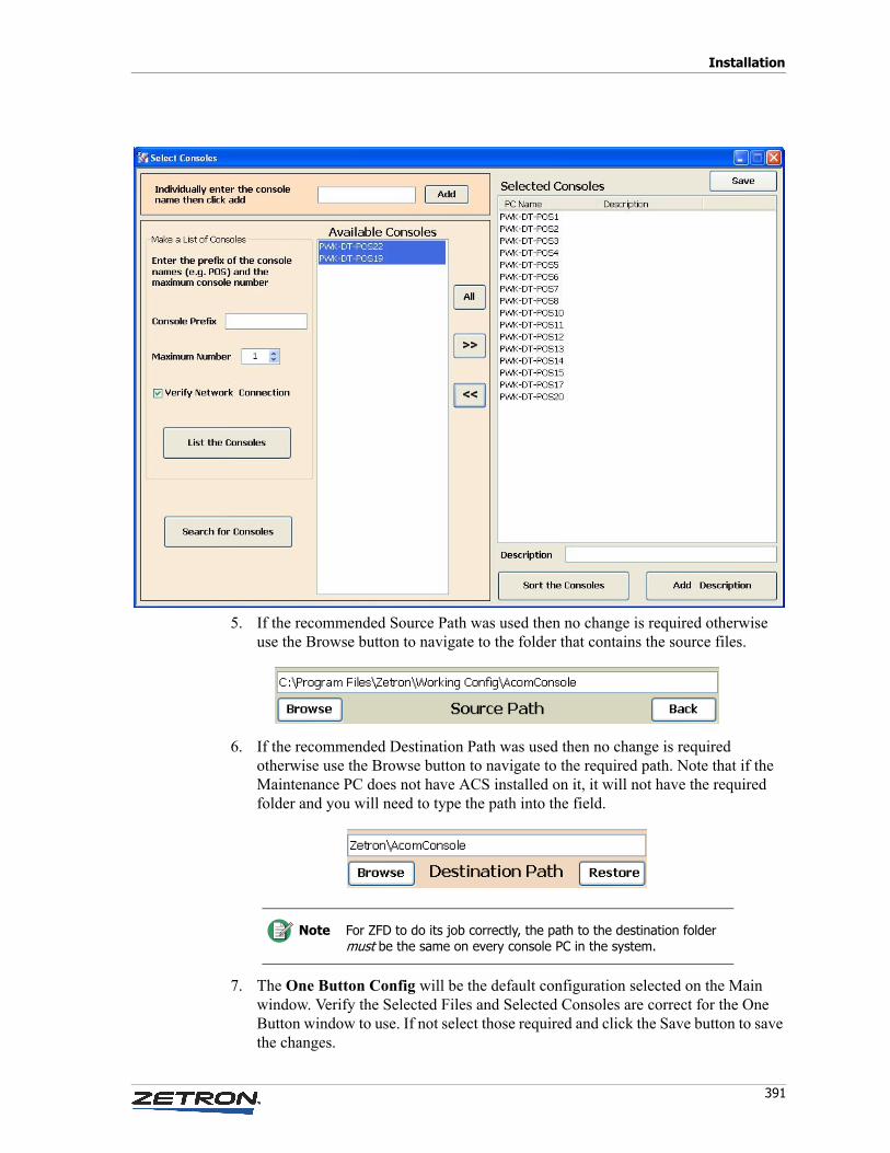
391
Installation
5. If the recommended Source Path was used then no change is required otherwise use the Browse button to navigate to the folder that contains the source files.
6. If the recommended Destination Path was used then no change is required otherwise use the Browse button to navigate to the required path. Note that if the Maintenance PC does not have ACS installed on it, it will not have the required folder and you will need to type the path into the field.
7. The One Button Config will be the default configuration selected on the Main window. Verify the Selected Files and Selected Consoles are correct for the One Button window to use. If not select those required and click the Save button to save the changes.
Note For ZFD to do its job correctly, the path to the destination folder must be the same on every console PC in the system.

Appendix C: Distributing Console Files
392 025-9529P
The User Interface
This section describes the four major screens found in ZFD, and the parameters found on each screen.
One Button Window
If ZFD has been initialized properly and no command line options have been added to the shortcut used to start it, the software will open the One Button window. If the software cannot find the FileDistributor.xml file, or there are no consoles defined in the FileDistributor.xml file, then the program opens the Main window.
The One Button window can also be opened by clicking on the button for that purpose located in the lower left corner of the Main window.
The upper half of the One Button window contains a single button labeled Send Files to All Consoles. Clicking on this button causes ZFD to execute the configuration called One Button Config as it is currently programmed. By default the One Button Config sends all of the files in the Source Path to all of the console PCs that ZFD has on file. From the
393
The User Interface
Main window, you can alter the One Button Config to include only certain consoles or some subset of all files if you wish to do so.
The bottom half of the One Button window contains a list and a button labeled Send Files to Selected Console. You may select an individual console from the list of consoles covered by the One Button Config and then click the button to send all of the files covered by that configuration to that single PC.
When either button is clicked, the program starts copying the files, and the progress of the copy operation is displayed.
This window allows people unfamiliar with the details of the system to refresh the Acom console configuration files on console PCs.
Main Window
The Main window is used by those personnel that setup and maintain the Acom console system. This window displays the consoles to which ZFD can copy files, the files it has to copy, the important paths for locating files and where to copy them to, and the controls necessary for editing the One Button Config or creating additional configurations.
The Main window can also be used to manually copy selected files to individual machines when the need arises.
Note The selection methods available in any of the lists in the Main window are the standard selection methods found in Windows-based software. To select a single item, click on it. To select multiple random items, hold down the Control (Ctrl) key and click on them. To select a contiguous block, click the first item, hold down a Shift key, and click the last item. The first item, last item, and all of the items in between the two are selected.
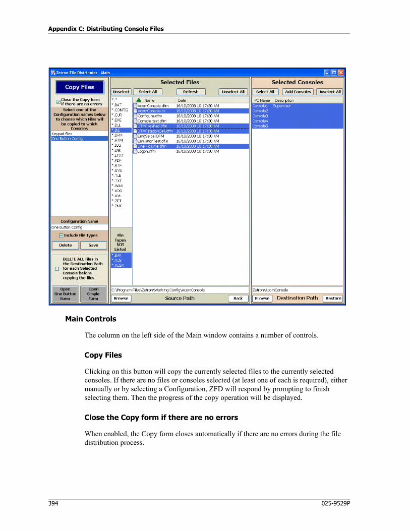
Appendix C: Distributing Console Files
394 025-9529P
Main Controls
The column on the left side of the Main window contains a number of controls.
Copy Files
Clicking on this button will copy the currently selected files to the currently selected consoles. If there are no files or consoles selected (at least one of each is required), either manually or by selecting a Configuration, ZFD will respond by prompting to finish selecting them. Then the progress of the copy operation will be displayed.
Close the Copy form if there are no errors
When enabled, the Copy form closes automatically if there are no errors during the file distribution process.
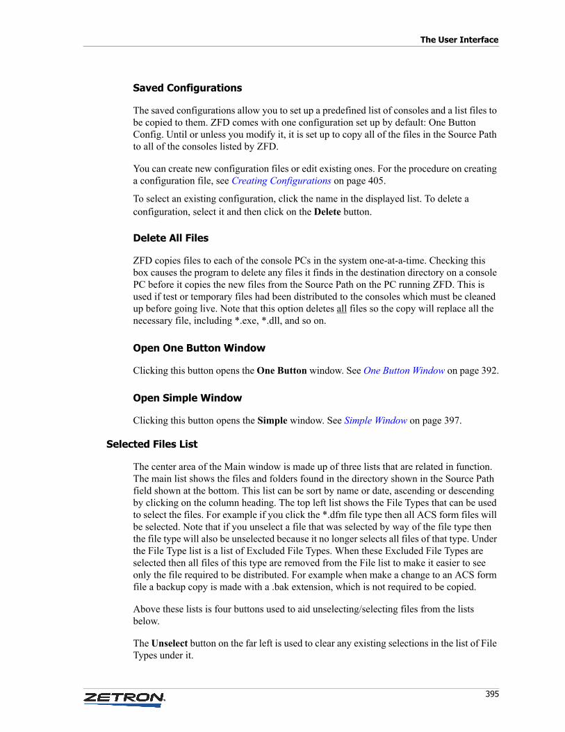
395
The User Interface
Saved Configurations
The saved configurations allow you to set up a predefined list of consoles and a list files to be copied to them. ZFD comes with one configuration set up by default: One Button Config. Until or unless you modify it, it is set up to copy all of the files in the Source Path to all of the consoles listed by ZFD.
You can create new configuration files or edit existing ones. For the procedure on creating a configuration file, see Creating Configurations on page 405.
To select an existing configuration, click the name in the displayed list. To delete a configuration, select it and then click on the Delete button.
Delete All Files
ZFD copies files to each of the console PCs in the system one-at-a-time. Checking this box causes the program to delete any files it finds in the destination directory on a console PC before it copies the new files from the Source Path on the PC running ZFD. This is used if test or temporary files had been distributed to the consoles which must be cleaned up before going live. Note that this option deletes all files so the copy will replace all the necessary file, including *.exe, *.dll, and so on.
Open One Button Window
Clicking this button opens the One Button window. See One Button Window on page 392.
Open Simple Window
Clicking this button opens the Simple window. See Simple Window on page 397.
Selected Files List
The center area of the Main window is made up of three lists that are related in function. The main list shows the files and folders found in the directory shown in the Source Path field shown at the bottom. This list can be sort by name or date, ascending or descending by clicking on the column heading. The top left list shows the File Types that can be used to select the files. For example if you click the *.dfm file type then all ACS form files will be selected. Note that if you unselect a file that was selected by way of the file type then the file type will also be unselected because it no longer selects all files of that type. Under the File Type list is a list of Excluded File Types. When these Excluded File Types are selected then all files of this type are removed from the File list to make it easier to see only the file required to be distributed. For example when make a change to an ACS form file a backup copy is made with a .bak extension, which is not required to be copied.
Above these lists is four buttons used to aid unselecting/selecting files from the lists below.
The Unselect button on the far left is used to clear any existing selections in the list of File Types under it.

Appendix C: Distributing Console Files
396 025-9529P
The Select All button selects all the files and folders listed below it.
The Refresh button forces ZFD to read the file names found in the Source PAth again and to update the list.
The Unselect All button is used to clear any existing selections listed below it.
Under the lists is the Source Path field. This directory holds all of the files that can be copied by ZFD on to console PCs in the system. Clicking on the Browse button under it opens a browser dialog to allow you establish the correct path by navigating to the correct folder. Note that you can all open any folders shown in the File list by double clicking on them. The Back button takes the Source Path up one folder.
Selected Consoles List
This pane is on the far right of the Main window. The list displayed here is all of the console PCs that ZFD is aware of. The names can be selected individually. Clicking on the Select All button at the top of the pane selects the entire list at once. Clicking on the Unselect All button clears the selection for any console names that are currently selected.
Clicking on the Add Consoles button at the top of the pane opens the Console Selection window. It is from this window that you can add new/delete console names to the list and add a description to each Console name.
Destination Path
Under the Consoles list is the Destination Path. The parameter field is used to specify the remainder of the path to the destination folder on the console PCs. ZFD takes the console name provided and adds the string found in this field to come up with the full path from the PC running ZFD to the console folder to which it is copying the files. This means that the path must be the same on all of the console PCs.
This parameter can be entered by just typing the path into the field, if you know what it is. You can also click on the Browse button under it and navigate to the correct folder on one of the maintenance PCs to establish the path if it is setup the same as a Console PC.
Clicking on the Restore button will change the path to the default value of:
Zetron\AcomConsoles
This default path is the one recommended in this manual when the Zetron folder is shared on each Console PC.
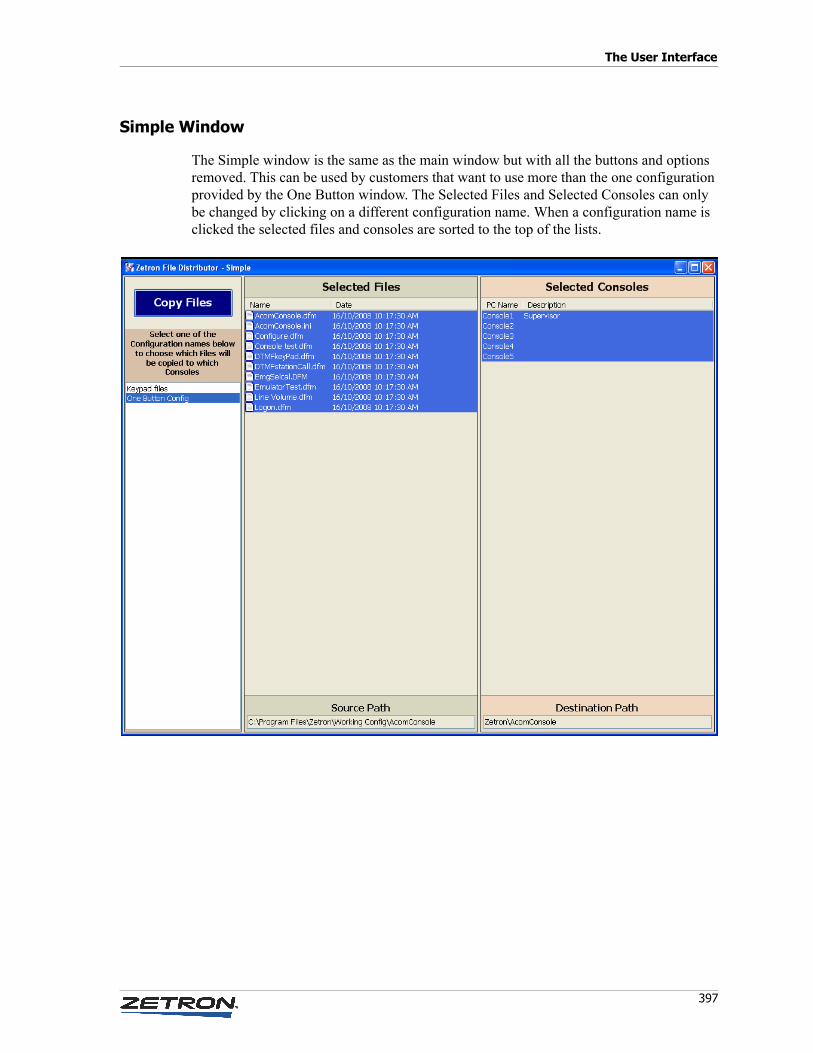
397
The User Interface
Simple Window
The Simple window is the same as the main window but with all the buttons and options removed. This can be used by customers that want to use more than the one configuration provided by the One Button window. The Selected Files and Selected Consoles can only be changed by clicking on a different configuration name. When a configuration name is clicked the selected files and consoles are sorted to the top of the lists.
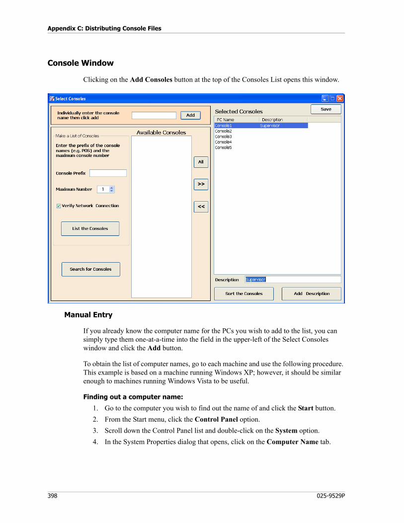
Appendix C: Distributing Console Files
398 025-9529P
Console Window
Clicking on the Add Consoles button at the top of the Consoles List opens this window.
Manual Entry
If you already know the computer name for the PCs you wish to add to the list, you can simply type them one-at-a-time into the field in the upper-left of the Select Consoles window and click the Add button.
To obtain the list of computer names, go to each machine and use the following procedure. This example is based on a machine running Windows XP; however, it should be similar enough to machines running Windows Vista to be useful.
Finding out a computer name:
1. Go to the computer you wish to find out the name of and click the Start button.
2. From the Start menu, click the Control Panel option.
3. Scroll down the Control Panel list and double-click on the System option.
4. In the System Properties dialog that opens, click on the Computer Name tab.

399
The User Interface
5. On the Computer name tab, locate the two lines Full computer name: and Domain:. Subtract the entry found under Domain: from the Full Computer name: entry to arrive at the computer name that ZFD is looking for.
For the example dialog shown here, you would subtract zetron.com from TPBKIRK.zetron.com to end up with a computer name of TP-BKIRK.
Let the PC Find the Consoles
In many systems, the console PCs will be dedicated machines that were purchased and configured specifically to be used at console positions. In cases like this, the PCs will have been given names during their set up that follow some sort of logical/sequential convention. An example would be a three position system with console PCs named POS-1, POS-2, and POS-3 for positions 1, 2, and 3. If this is true, then you can use the options found in the lower-left portion of the Select Consoles dialog to instruct the computer running ZFD to search the portion of the network accessible to it for PCs that have names which fall within the parameters entered.
Console Prefix
This field is for the non-numeric portion of the console names. ZFD does not allow for any wild-card character in between this string and the sequential number portion of the console names. This means that this string must be complete and identical for each of the console PCs. The only character that can differ in their names is the number at the very end.
Maximum Number
This field sets the maximum console number that ZFD will search for. For example, if it is set to 10 and there are PCs on the network with the correct prefix but their name ends in a number higher than 10, they will not be displayed on the Available Consoles list.
Verify Network Connection
If this check box is selected, ZFD will attempt to ping each console as it works its way through the list of possible combinations defined by Console Prefix and Maximum Number. If there is no response to its ping, ZFD will prompt you to choose whether or not to add that console name to the list of available consoles. This way, if there are gaps in the

Appendix C: Distributing Console Files
400 025-9529P
consoles available on the system, you do not end up with your list cluttered with useless PC names.
List the Consoles
Clicking this button causes ZFD to carry out the PC name search defined by the Console Prefix, Maximum Number, and Verify Network Connection parameters. If the Verify Network Connection check box is selected, names will be added to the Available Consoles list as their presence on the network is confirmed. If the ping attempt to a particular name fails, ZFD will notify you of this fact and ask if you want to add the name in question to the Available Consoles list anyway.
Search for Consoles
This button allows you to take a different approach to compiling a list of console PCs; one that can be very helpful in systems where the console PC names do not follow any uniform convention.
When you click on the Search for Consoles button, ZFD goes out and tries to ping all of the computers it can access on its portion of the network and it displays the PC names of all of the successful attempts in the Available Consoles list.
All, >>, and << Buttons
The three buttons that appear in the space between the Available Consoles list and the Selected Consoles list are used to move computer names from one list to the other.
Clicking All button will move all of the PC names on the Available Consoles list to the Selected Consoles list in one operation.
Clicking the >> button will move whichever PC names are currently selected on the Available Consoles list to the Selected Consoles list.
Clicking the << button will move whichever names are currently selected on the Selected Consoles list to the Available Consoles list.
The computer names can also be moved between list by the normal drag-and-drop operation.
Sort the Consoles
Clicking the Sort Consoles button causes the Selected Consoles list to be sorted alphabetically by the PC names.
401
Setting Up and Using ZFD
Add Description
This button is used to add a brief description next to an individual console PC name. This feature is used to make it easier for technicians to tell which PC is being referred to when the console PC name does not really provide enough information by itself.
To use this feature, you would select a name from the Selected Consoles list, type a brief description in the Description field, and click the Add Description button. Descriptions can be edited or removed simply by repeating this procedure.
Save
When the computer names in the Selected Consoles list is complete click the Save button to save the changes and close the window. Any names shown on the Available Consoles list are lost. Only those names that have been moved to the Selected Consoles list are retained.
Setting Up and Using ZFD
The procedures that follow are useful in refining the settings for the ZFD to maximize its usefulness in your Acom console system.
Command Line Options
There are command line options that can follow the executable shortcut used to start ZFD. To display the list of command line options, use /?, as shown in the following example:
FileDistributor.exe /?
The command line options are described in the following subsections.
Open Form Command Line Options
There are a number of command line options for opening forms. Some options must be indicated before other options (first option and second option). The first option controls which window is initially opened and the second option determines if you can swap to the main window. If no command line arguments are given, the software will open the One Button window without the ability to swap to the Main window. For example, to open the Simple with the ability to open the Main window the command-line would be FileDistributor.exe /S /Y. The allowed option values are:
Note “Open form command line options” and “command line copy options” are mutually exclusive. The last option will override the others.
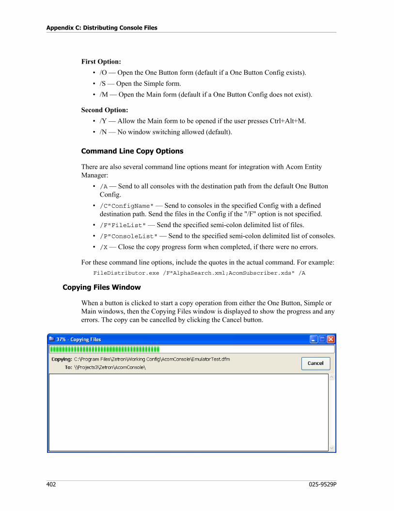
Appendix C: Distributing Console Files
402 025-9529P
First Option:
• /O — Open the One Button form (default if a One Button Config exists).
• /S — Open the Simple form.
• /M — Open the Main form (default if a One Button Config does not exist).
Second Option:
• /Y — Allow the Main form to be opened if the user presses Ctrl+Alt+M.
• /N — No window switching allowed (default).
Command Line Copy Options
There are also several command line options meant for integration with Acom Entity Manager:
• /A — Send to all consoles with the destination path from the default One Button Config.
• /C"ConfigName" — Send to consoles in the specified Config with a defined destination path. Send the files in the Config if the "/F" option is not specified.
• /F"FileList" — Send the specified semi-colon delimited list of files.
• /P"ConsoleList" — Send to the specified semi-colon delimited list of consoles.
• /X — Close the copy progress form when completed, if there were no errors.
For these command line options, include the quotes in the actual command. For example:
FileDistributor.exe /F"AlphaSearch.xml;AcomSubscriber.xds" /A
Copying Files Window
When a button is clicked to start a copy operation from either the One Button, Simple or Main windows, then the Copying Files window is displayed to show the progress and any errors. The copy can be cancelled by clicking the Cancel button.
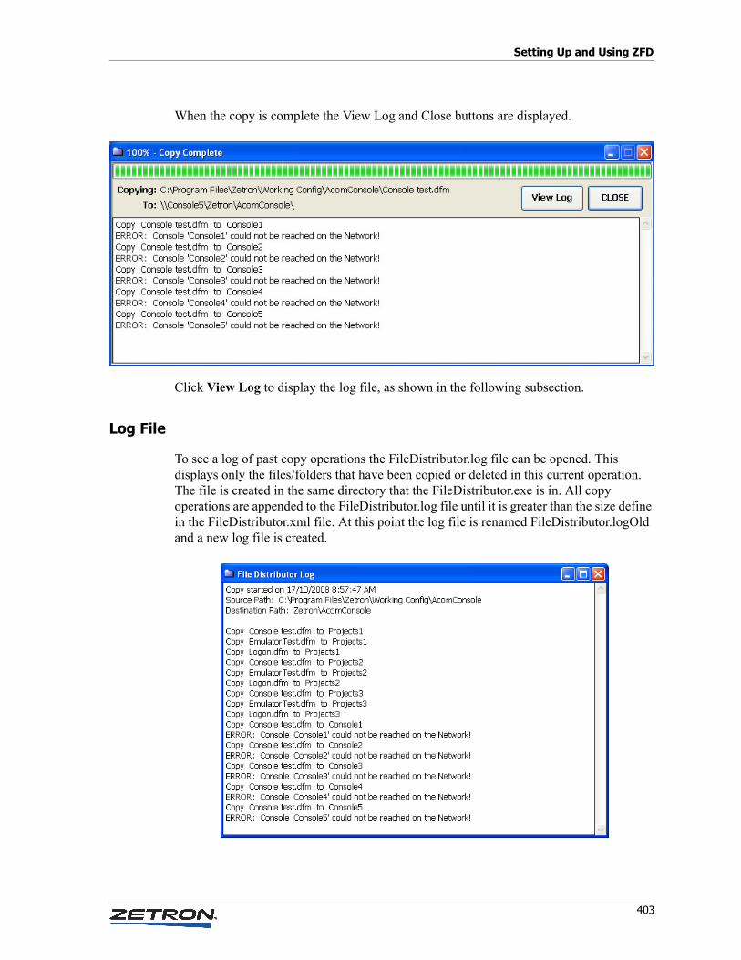
403
Setting Up and Using ZFD
When the copy is complete the View Log and Close buttons are displayed.
Click View Log to display the log file, as shown in the following subsection.
Log File
To see a log of past copy operations the FileDistributor.log file can be opened. This displays only the files/folders that have been copied or deleted in this current operation. The file is created in the same directory that the FileDistributor.exe is in. All copy operations are appended to the FileDistributor.log file until it is greater than the size define in the FileDistributor.xml file. At this point the log file is renamed FileDistributor.logOld and a new log file is created.

Appendix C: Distributing Console Files
404 025-9529P
Editing the Selected Consoles List
To use the procedures described here it is important that you know the name assigned to each of the console PCs in your network. If you are uncertain of what they are, use the procedure described on page Finding out a computer name: to find out.
♦ Adding one or two PCs to the Select Consoles list:
1. Start ZFD with the command-line options to open the Main window.
2. Click the Add Consoles button in the lower left corner to open the Select Consoles window.
3. Type the new console names into the field at the top of the Select Consoles window one-at-a-time and click on the Add button next to the field.
♦ Adding a large number of consoles to the Select Consoles list:
1. Start ZFD with the command-line options to open the Main window.
2. Click the Add Consoles button in the lower left corner to open the Select Consoles window.
3. Use the search tools on the lower left of the Select Consoles window to populate the Available Consoles list.
4. Select the names you wish to add from the Available Consoles list and use the >> button to move the names to the Selected Consoles list.
5. If you wish to add a description to any of the new names:
a. Select that name in the Selected Consoles list.
b. Type a brief description in the Description field.
c. Click the Add Description button.
6. Close the Select Consoles window.
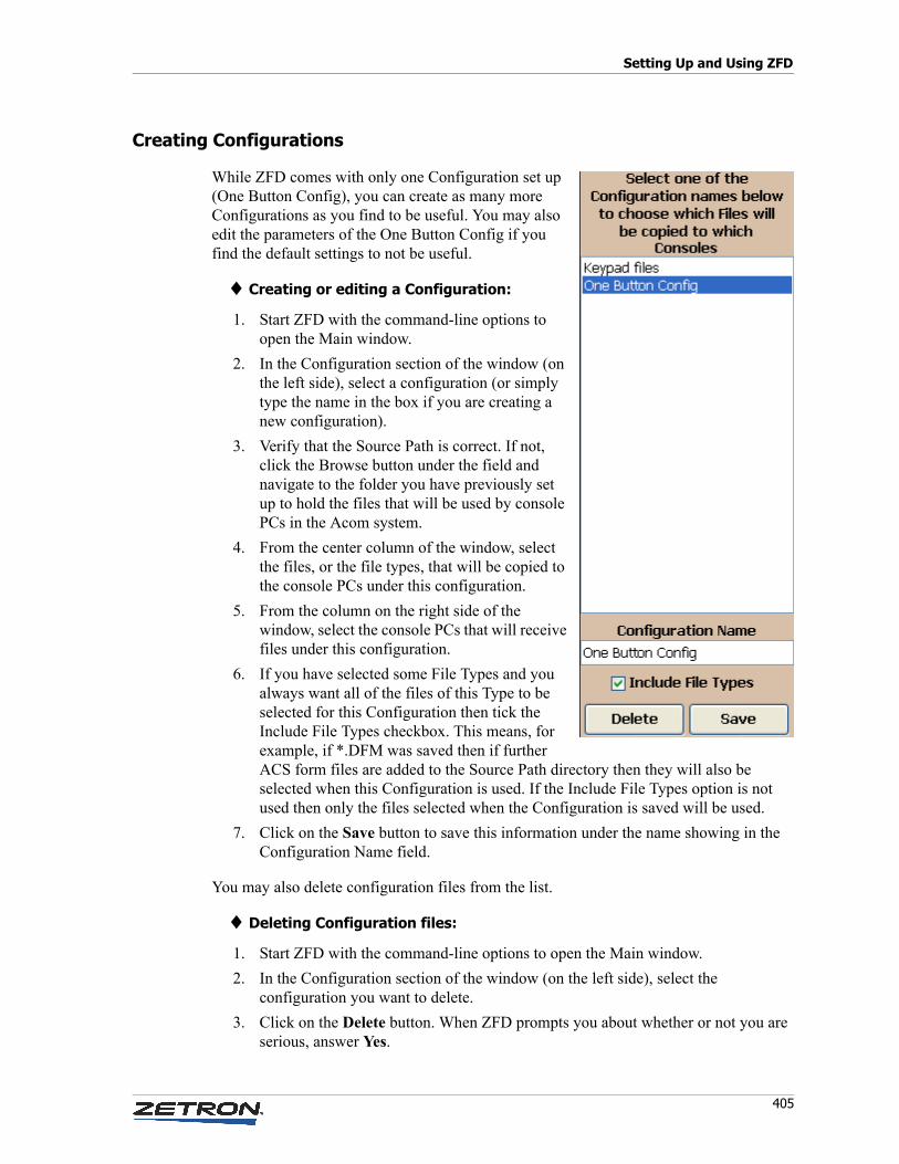
405
Setting Up and Using ZFD
Creating Configurations
While ZFD comes with only one Configuration set up (One Button Config), you can create as many more Configurations as you find to be useful. You may also edit the parameters of the One Button Config if you find the default settings to not be useful.
♦ Creating or editing a Configuration:
1. Start ZFD with the command-line options to open the Main window.
2. In the Configuration section of the window (on the left side), select a configuration (or simply type the name in the box if you are creating a new configuration).
3. Verify that the Source Path is correct. If not, click the Browse button under the field and navigate to the folder you have previously set up to hold the files that will be used by console PCs in the Acom system.
4. From the center column of the window, select the files, or the file types, that will be copied to the console PCs under this configuration.
5. From the column on the right side of the window, select the console PCs that will receive files under this configuration.
6. If you have selected some File Types and you always want all of the files of this Type to be selected for this Configuration then tick the Include File Types checkbox. This means, for example, if *.DFM was saved then if further ACS form files are added to the Source Path directory then they will also be selected when this Configuration is used. If the Include File Types option is not used then only the files selected when the Configuration is saved will be used.
7. Click on the Save button to save this information under the name showing in the Configuration Name field.
You may also delete configuration files from the list.
♦ Deleting Configuration files:
1. Start ZFD with the command-line options to open the Main window.
2. In the Configuration section of the window (on the left side), select the configuration you want to delete.
3. Click on the Delete button. When ZFD prompts you about whether or not you are serious, answer Yes.
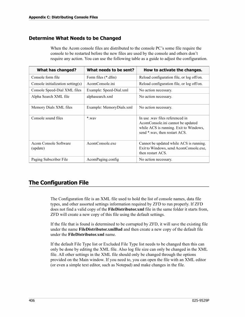
Appendix C: Distributing Console Files
406 025-9529P
Determine What Needs to be Changed
When the Acom console files are distributed to the console PC’s some file require the console to be restarted before the new files are used by the console and others don’t require any action. You can use the following table as a guide to adjust the configuration.
The Configuration File
The Configuration file is an XML file used to hold the list of console names, data file types, and other assorted settings information required by ZFD to run properly. If ZFD does not find a valid copy of the FileDistributor.xml file in the same folder it starts from, ZFD will create a new copy of this file using the default settings.
If the file that is found is determined to be corrupted by ZFD, it will save the existing file under the name FileDistributor.xmlBad and then create a new copy of the default file under the FileDistributor.xml name.
If the default File Type list or Excluded File Type list needs to be changed then this can only be done by editing the XML file. Also log file size can only be changed in the XML file. All other settings in the XML file should only be changed through the options provided on the Main window. If you need to, you can open the file with an XML editor (or even a simple text editor, such as Notepad) and make changes in the file.
What has changed? What needs to be sent? How to activate the changes.
Console form file Form files (*.dfm) Reload configuration file, or log off/on.
Console initialization setting(s) AcomConsole.ini Reload configuration file, or log off/on.
Console Speed-Dial XML files Example: Speed-Dial.xml No action necessary.
Alpha Search XML file alphasearch.xml No action necessary.
Memory Dials XML files Example: MemoryDials.xml No action necessary.
Console sound files *.wav In use .wav files referenced in AcomConsole.ini cannot be updated while ACS is running. Exit to Windows, send *.wav, then restart ACS.
Acom Console Software(update)
AcomConsole.exe Cannot be updated while ACS is running. Exit to Windows, send AcomConsole.exe, then restart ACS.
Paging Subscriber File AcomPaging.config No action necessary.
407
The Configuration File
LogSize Setting
The LogSize setting is used to define the maximum size for the log file created by ZFD. Whenever the program is started, it checks the current size of the log file against the maximum size defined by this parameter. If the log file is too large, ZFD renames the file as FileDistributor.logOld and then starts a new log file.
<LogSize>1000000</LogSize>
As shown here, the default setting is 1 megabyte. This parameter can only be altered by editing the FileDistributor.xml file. If you decide that you need to change the file size to something other than the default value, use the following procedure.
♦ To set the log file size:
1. While ZFD is not running, open the FileDistributor.xml file.
2. Scroll down to the line for LogSize and edit the number defining the maximum size for the log file.
3. Save the changes to the FileDistributor.xml file and close it.
FileTypes Setting
The FileTypes setting is basically just a list of all of the file types (recognized by their file name extensions) that ZFD is allowed to copy onto console PCs. This list can only be altered by editing the FileDistributor.xml file. If you decide that you need to change the list of file types to something other than the default list, use the following procedure.
♦ Editing the FileTypes list:
1. While ZFD is not running, open the FileDistributor.xml file.
2. Scroll down to the section containing the FileType entries and edit the list as necessary. To remove an entry, simply delete its entire line. To add a new entry, create a new line and add text similar to the following:<FileType>*.XXX</FileType>
Where the variable *.XXX is the file name extension of the new file type.
3. Save the changes to the FileDistributor.xml file and close it.
ExcludedFileTypes Setting
The ExcludedFileTypes setting is basically just a list of all of the file types (recognized by their file name extensions) that ZFD will NOT display in the File list. This list can only be altered by editing the FileDistributor.xml file. If you decide that you need to change the list of file types to something other than the default list, use the following procedure above.

Appendix C: Distributing Console Files
408 025-9529P
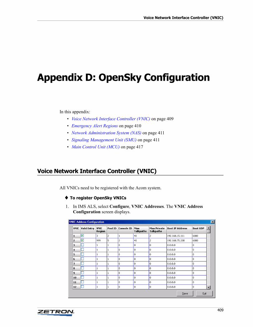
Voice Network Interface Controller (VNIC)
409
Appendix D: OpenSky Configuration
In this appendix:
• Voice Network Interface Controller (VNIC) on page 409
• Emergency Alert Regions on page 410
• Network Administration System (NAS) on page 411
• Signaling Management Unit (SMU) on page 411
• Main Control Unit (MCU) on page 417
Voice Network Interface Controller (VNIC)
All VNICs need to be registered with the Acom system.
♦ To register OpenSky VNICs
1. In IMS ALS, select Configure, VNIC Addresses. The VNIC Address Configuration screen displays.
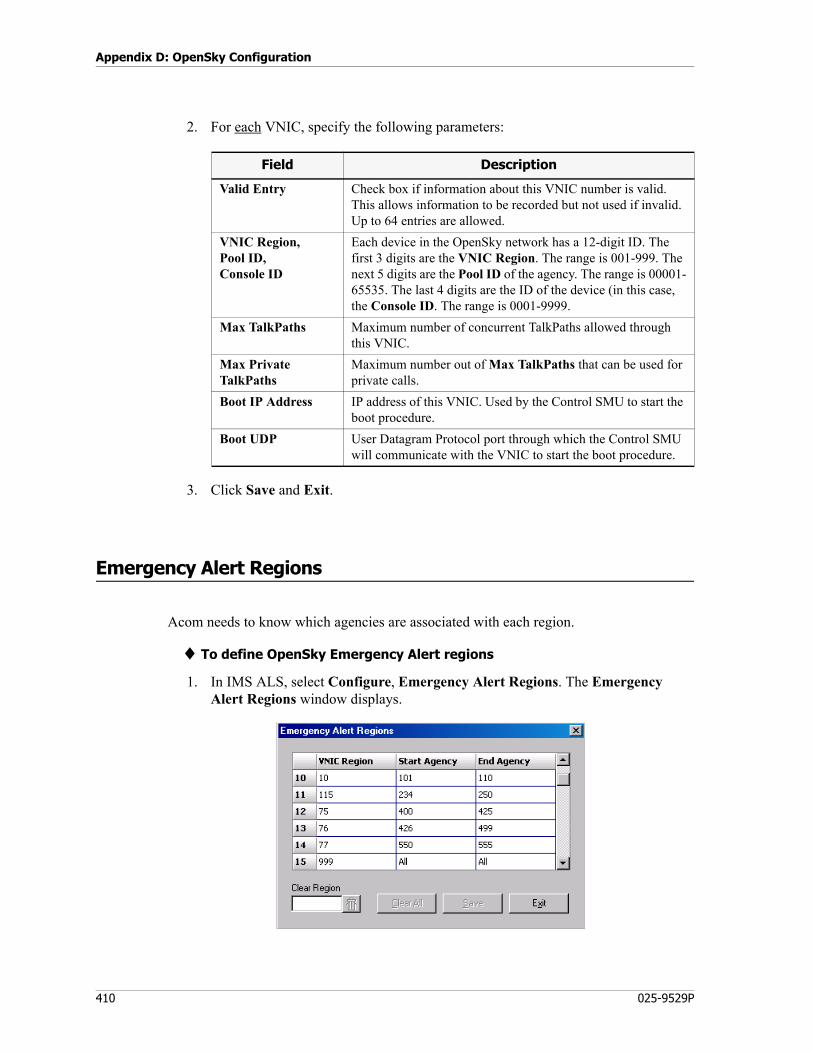
Appendix D: OpenSky Configuration
410 025-9529P
2. For each VNIC, specify the following parameters:
3. Click Save and Exit.
Emergency Alert Regions
Acom needs to know which agencies are associated with each region.
♦ To define OpenSky Emergency Alert regions
1. In IMS ALS, select Configure, Emergency Alert Regions. The Emergency Alert Regions window displays.
Field Description
Valid Entry Check box if information about this VNIC number is valid. This allows information to be recorded but not used if invalid. Up to 64 entries are allowed.
VNIC Region,Pool ID,Console ID
Each device in the OpenSky network has a 12-digit ID. The first 3 digits are the VNIC Region. The range is 001-999. The next 5 digits are the Pool ID of the agency. The range is 00001-65535. The last 4 digits are the ID of the device (in this case, the Console ID. The range is 0001-9999.
Max TalkPaths Maximum number of concurrent TalkPaths allowed through this VNIC.
Max Private TalkPaths
Maximum number out of Max TalkPaths that can be used for private calls.
Boot IP Address IP address of this VNIC. Used by the Control SMU to start the boot procedure.
Boot UDP User Datagram Protocol port through which the Control SMU will communicate with the VNIC to start the boot procedure.
411
Network Administration System (NAS)
2. On each line, enter one of the VNIC region numbers, just as on the VNIC Address Configuration screen.
3. For each VNIC region, specify the start and end numbers of the agencies to include in that region. The range of values is 1-999. The maximum number of agencies supported for each region is 99. If you enter a value in either the Start Agency or End Agency field, such that the difference between the two field values is greater than 99, All will be entered in both fields.
4. Click Save and Exit.
5. To configure the color and sound associated with the Emergency Alerts button in ACS, see the following entries in the AcomConsole.ini file: MdcEmergencyAlert=color on page 334, MdcEmergency=filename.wav on page 369, and EmergencyAlertAudiblePeriod=X on page 373.
Network Administration System (NAS)
A central database of OpenSky subscriber information (names and IDs of regions, agencies, voice groups, and end users) is maintained on a dedicated PC. This PC runs a Windows service called NAS Service, which checks for changes on the OpenSky network, updates the database, and notifies each console that there is an updated database.
The NAS Service can be configured by way of Internet Explorer. The default address is http://localhost:22101 on the PC where the service is installed.
Each console needs to have a copy of the database. Each console runs a Windows service called CSDS Service, which communicates with the NAS Service on the NAS PC. When a new database is available, the console downloads it, closes its local database and deletes it, renames the new database to a local name, and reopens the database.
Each Voice Network Interface Controller (VNIC) maintains one subscriber alias file. Updates can be downloaded automatically (see [Acom Updates] on page 328).
Signaling Management Unit (SMU)
SMU cards interface the OpenSky network. They generate and receive all messages and convert VoIP packets to PCM. There is one Control SMU and one or more Voice SMUs. The Control SMU handles control messages. The Voice SMUs handle the OpenSky TalkPaths (voice channels). Configure the SMUs as follows:
1. In IMS ALS, right-click the SMU card and select Extended Card Parameters.
2. From the Mode drop-down list, select VNIC Control if this is a Control SMU, or VNIC TalkPath if it is a Voice SMU.
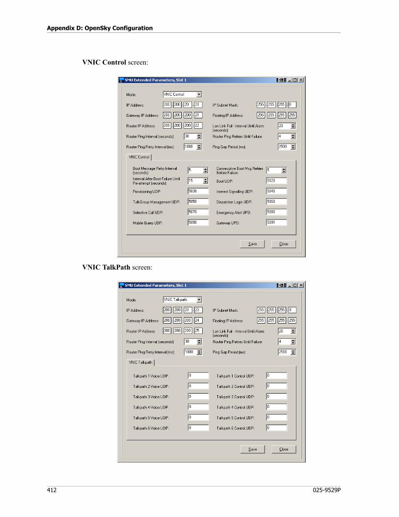
Appendix D: OpenSky Configuration
412 025-9529P
VNIC Control screen:
VNIC TalkPath screen:
413
Signaling Management Unit (SMU)
3. On all SMUs, specify the following parameters:
4. On the Control SMU only, specify the following parameters:
Field Description
Mode Specifies whether this is a Control SMU or a Voice SMU.
IP Address Actual IP address of the SMU. Unique to each SMU.
IP Subnet Mask Tells the router which parts of the IP address identify the network and which identify the host.
Gateway IP Address IP address of the gateway used to translate data between the Acom network and the OpenSky network.
Floating IP Address The IP address shown in all communications between the Acom system and the VNIC. Must be the same on the SMU and its redundant SMU, and must be unique to each pair.
Router IP Address IP address of the router on the Acom network.
LAN Link Fail - Interval Until Alarm
The number of seconds the SMU’s Ethernet connection can be down before triggering an alarm. Should be set to ≤10.
Router Ping Interval The number of seconds between normal pings by the SMU to the router to verify the router is not in failure state.
Router Ping Retry Interval
If the SMU gets no response to a router ping, it will wait this number of milliseconds and then ping again.
Router Ping Retries Until Failure
The number of times the SMU will ping the router before failure state is assumed.
Ping Gap Period The number of milliseconds the SMU will wait between pings after a ping failure.
Field Description
Boot Retry Timer After Max Boot Retries unsuccessful attempts to boot a VNIC, the SMU will wait this number of seconds, then try again.
Max Boot Retries Number of attempts to boot the VNIC, after which the SMU will wait Boot Retry Timer seconds before trying to boot the VNIC again.
Boot Failed Timer Number of seconds between VNIC boot retries.
Boot UDP UDP port on the SMU through which it will communicate with the VNIC for booting.
Provisioning UDP UDP port on the SMU through which it will communicate with the VNIC for provisioning.
Internet Signaling UDP UDP port on the SMU through which it will communicate with the VNIC for interest signaling.
TalkGroup Management UDP UDP port on the SMU through which it will communicate with the VNIC for managing TalkGroups.
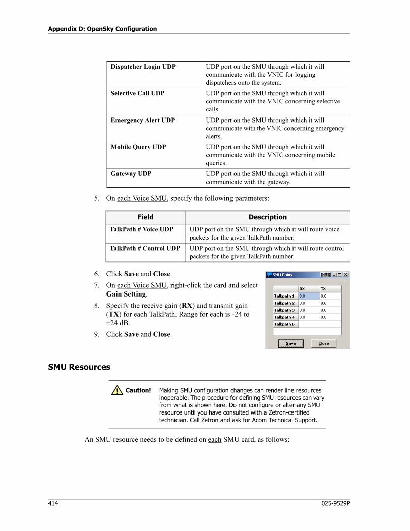
Appendix D: OpenSky Configuration
414 025-9529P
5. On each Voice SMU, specify the following parameters:
6. Click Save and Close.
7. On each Voice SMU, right-click the card and select Gain Setting.
8. Specify the receive gain (RX) and transmit gain (TX) for each TalkPath. Range for each is -24 to +24 dB.
9. Click Save and Close.
SMU Resources
An SMU resource needs to be defined on each SMU card, as follows:
Dispatcher Login UDP UDP port on the SMU through which it will communicate with the VNIC for logging dispatchers onto the system.
Selective Call UDP UDP port on the SMU through which it will communicate with the VNIC concerning selective calls.
Emergency Alert UDP UDP port on the SMU through which it will communicate with the VNIC concerning emergency alerts.
Mobile Query UDP UDP port on the SMU through which it will communicate with the VNIC concerning mobile queries.
Gateway UDP UDP port on the SMU through which it will communicate with the gateway.
Field Description
TalkPath # Voice UDP UDP port on the SMU through which it will route voice packets for the given TalkPath number.
TalkPath # Control UDP UDP port on the SMU through which it will route control packets for the given TalkPath number.
Caution! Making SMU configuration changes can render line resources inoperable. The procedure for defining SMU resources can vary from what is shown here. Do not configure or alter any SMU resource until you have consulted with a Zetron-certified technician. Call Zetron and ask for Acom Technical Support.
!
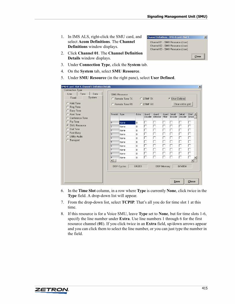
415
Signaling Management Unit (SMU)
1. In IMS ALS, right-click the SMU card, and select Acom Definitions. The Channel Definitions window displays.
2. Click Channel 01. The Channel Definition Details window displays.
3. Under Connection Type, click the System tab.
4. On the System tab, select SMU Resource.
5. Under SMU Resource (in the right pane), select User Defined.
6. In the Time Slot column, in a row where Type is currently None, click twice in the Type field. A drop-down list will appear.
7. From the drop-down list, select TCPIP. That’s all you do for time slot 1 at this time.
8. If this resource is for a Voice SMU, leave Type set to None, but for time slots 1-6, specify the line number under Extra. Use line numbers 1 through 6 for the first resource channel (01). If you click twice in an Extra field, up/down arrows appear and you can click them to select the line number, or you can just type the number in the field.
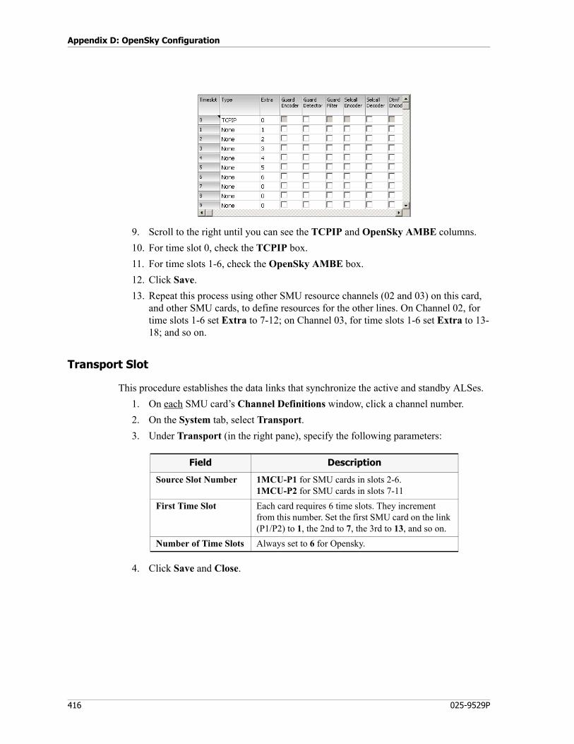
Appendix D: OpenSky Configuration
416 025-9529P
9. Scroll to the right until you can see the TCPIP and OpenSky AMBE columns.
10. For time slot 0, check the TCPIP box.
11. For time slots 1-6, check the OpenSky AMBE box.
12. Click Save.
13. Repeat this process using other SMU resource channels (02 and 03) on this card, and other SMU cards, to define resources for the other lines. On Channel 02, for time slots 1-6 set Extra to 7-12; on Channel 03, for time slots 1-6 set Extra to 13-18; and so on.
Transport Slot
This procedure establishes the data links that synchronize the active and standby ALSes.
1. On each SMU card’s Channel Definitions window, click a channel number.
2. On the System tab, select Transport.
3. Under Transport (in the right pane), specify the following parameters:
4. Click Save and Close.
Field Description
Source Slot Number 1MCU-P1 for SMU cards in slots 2-6.1MCU-P2 for SMU cards in slots 7-11
First Time Slot Each card requires 6 time slots. They increment from this number. Set the first SMU card on the link (P1/P2) to 1, the 2nd to 7, the 3rd to 13, and so on.
Number of Time Slots Always set to 6 for Opensky.
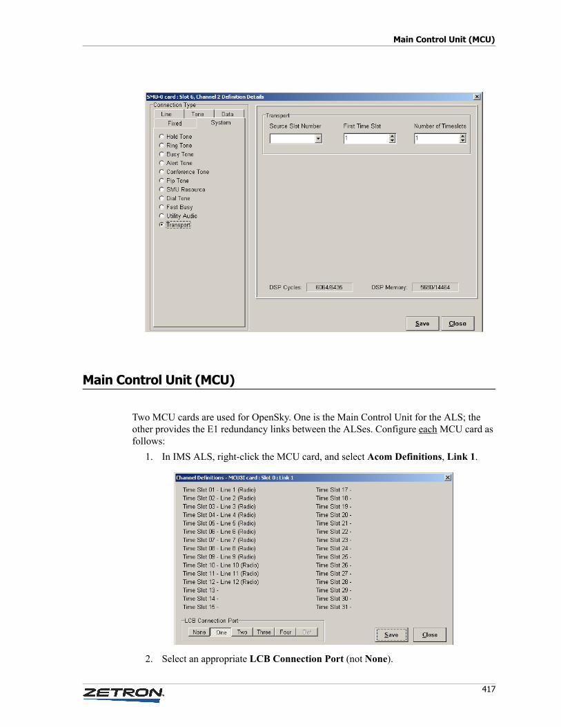
417
Main Control Unit (MCU)
Main Control Unit (MCU)
Two MCU cards are used for OpenSky. One is the Main Control Unit for the ALS; the other provides the E1 redundancy links between the ALSes. Configure each MCU card as follows:
1. In IMS ALS, right-click the MCU card, and select Acom Definitions, Link 1.
2. Select an appropriate LCB Connection Port (not None).
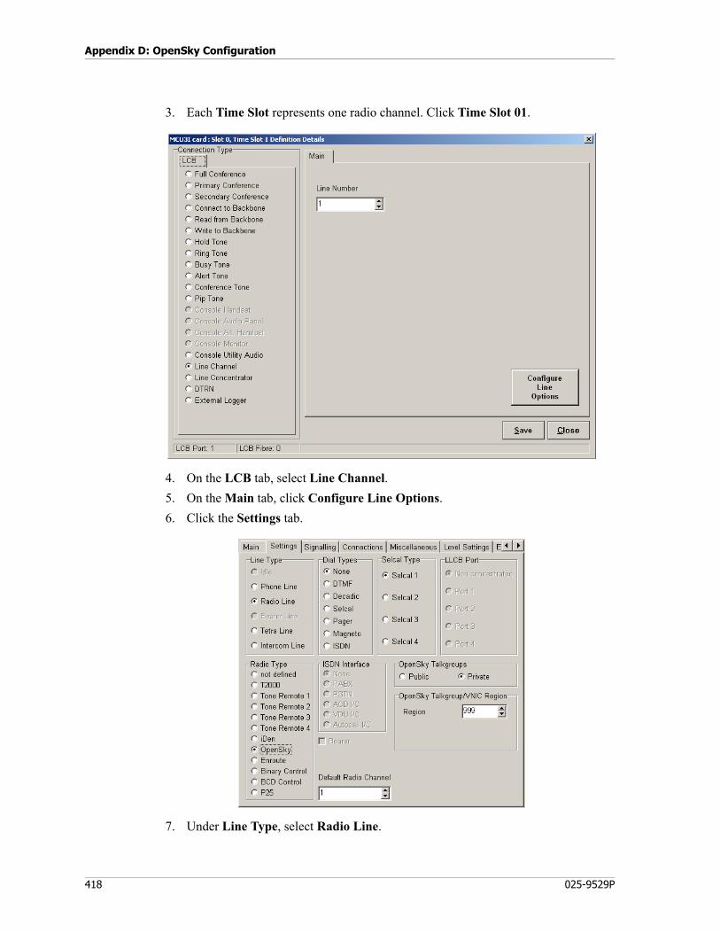
Appendix D: OpenSky Configuration
418 025-9529P
3. Each Time Slot represents one radio channel. Click Time Slot 01.
4. On the LCB tab, select Line Channel.
5. On the Main tab, click Configure Line Options.
6. Click the Settings tab.
7. Under Line Type, select Radio Line.
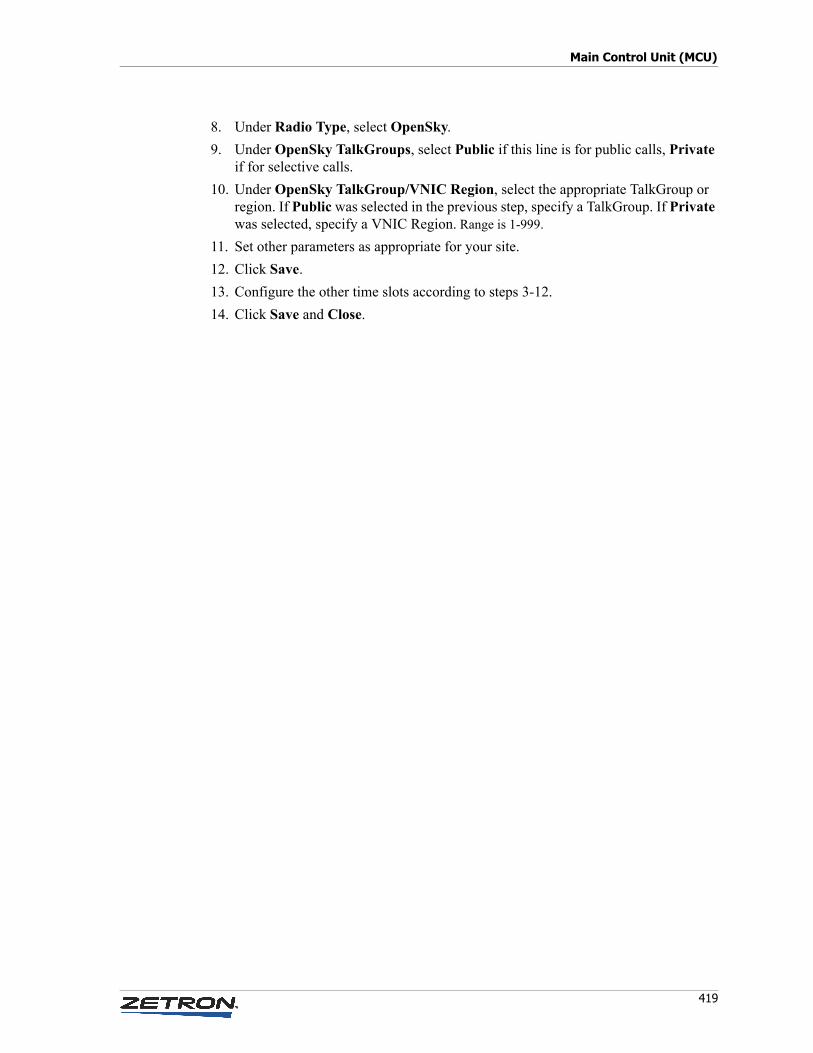
419
Main Control Unit (MCU)
8. Under Radio Type, select OpenSky.
9. Under OpenSky TalkGroups, select Public if this line is for public calls, Private if for selective calls.
10. Under OpenSky TalkGroup/VNIC Region, select the appropriate TalkGroup or region. If Public was selected in the previous step, specify a TalkGroup. If Private was selected, specify a VNIC Region. Range is 1-999.
11. Set other parameters as appropriate for your site.
12. Click Save.
13. Configure the other time slots according to steps 3-12.
14. Click Save and Close.

Appendix D: OpenSky Configuration
420 025-9529P
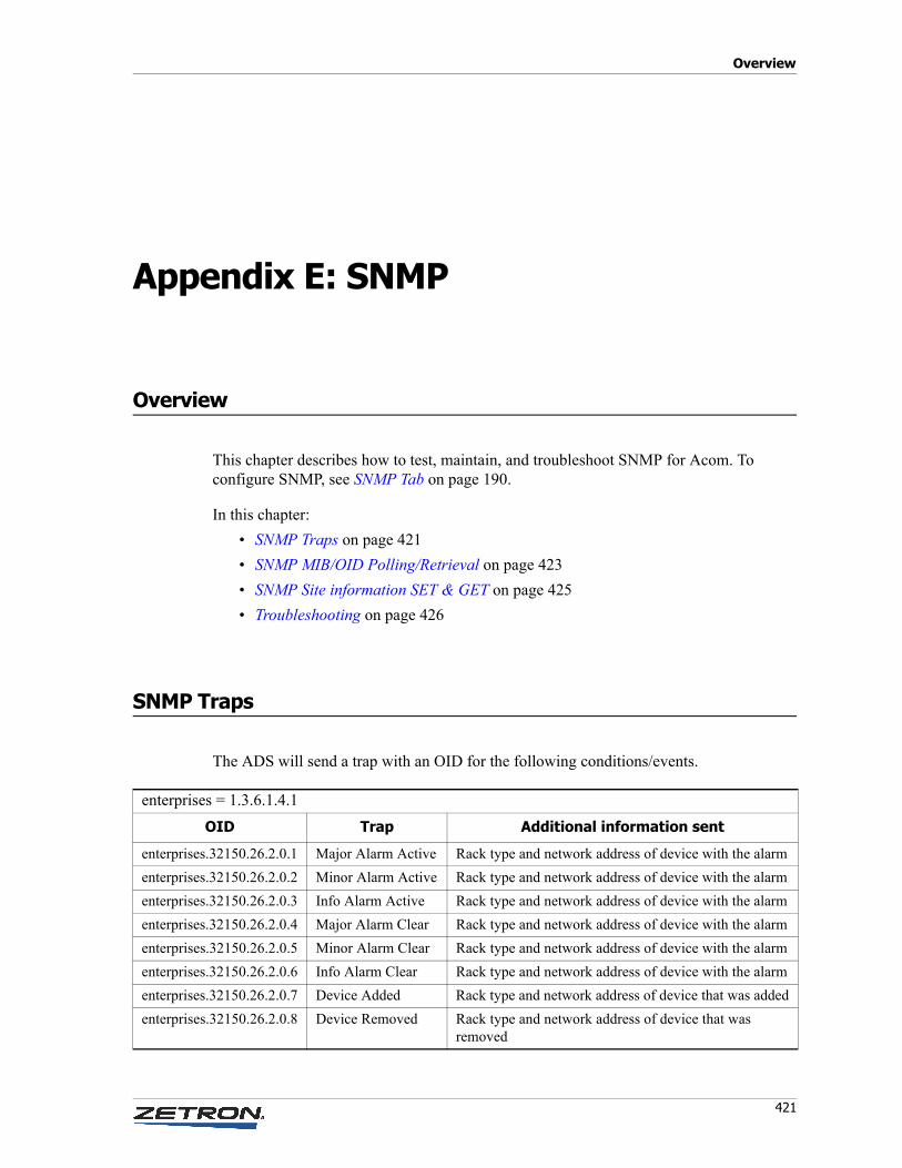
Overview
421
Appendix E: SNMP
Overview
This chapter describes how to test, maintain, and troubleshoot SNMP for Acom. To configure SNMP, see SNMP Tab on page 190.
In this chapter:
• SNMP Traps on page 421
• SNMP MIB/OID Polling/Retrieval on page 423
• SNMP Site information SET & GET on page 425
• Troubleshooting on page 426
SNMP Traps
The ADS will send a trap with an OID for the following conditions/events.
enterprises = 1.3.6.1.4.1
OID Trap Additional information sent
enterprises.32150.26.2.0.1 Major Alarm Active Rack type and network address of device with the alarm
enterprises.32150.26.2.0.2 Minor Alarm Active Rack type and network address of device with the alarm
enterprises.32150.26.2.0.3 Info Alarm Active Rack type and network address of device with the alarm
enterprises.32150.26.2.0.4 Major Alarm Clear Rack type and network address of device with the alarm
enterprises.32150.26.2.0.5 Minor Alarm Clear Rack type and network address of device with the alarm
enterprises.32150.26.2.0.6 Info Alarm Clear Rack type and network address of device with the alarm
enterprises.32150.26.2.0.7 Device Added Rack type and network address of device that was added
enterprises.32150.26.2.0.8 Device Removed Rack type and network address of device that was removed
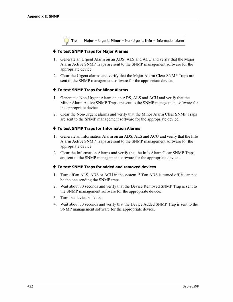
Appendix E: SNMP
422 025-9529P
♦ To test SNMP Traps for Major Alarms
1. Generate an Urgent Alarm on an ADS, ALS and ACU and verify that the Major Alarm Active SNMP Traps are sent to the SNMP management software for the appropriate device.
2. Clear the Urgent alarms and verify that the Major Alarm Clear SNMP Traps are sent to the SNMP management software for the appropriate device.
♦ To test SNMP Traps for Minor Alarms
1. Generate a Non-Urgent Alarm on an ADS, ALS and ACU and verify that the Minor Alarm Active SNMP Traps are sent to the SNMP management software for the appropriate device.
2. Clear the Non-Urgent alarms and verify that the Minor Alarm Clear SNMP Traps are sent to the SNMP management software for the appropriate device.
♦ To test SNMP Traps for Information Alarms
1. Generate an Information Alarm on an ADS, ALS and ACU and verify that the Info Alarm Active SNMP Traps are sent to the SNMP management software for the appropriate device.
2. Clear the Information Alarms and verify that the Info Alarm Clear SNMP Traps are sent to the SNMP management software for the appropriate device.
♦ To test SNMP Traps for added and removed devices
1. Turn off an ALS, ADS or ACU in the system. *If an ADS is turned off, it can not be the one sending the SNMP traps.
2. Wait about 30 seconds and verify that the Device Removed SNMP Trap is sent to the SNMP management software for the appropriate device.
3. Turn the device back on.
4. Wait about 30 seconds and verify that the Device Added SNMP Trap is sent to the SNMP management software for the appropriate device.
Tip Major = Urgent, Minor = Non-Urgent, Info = Information alarm
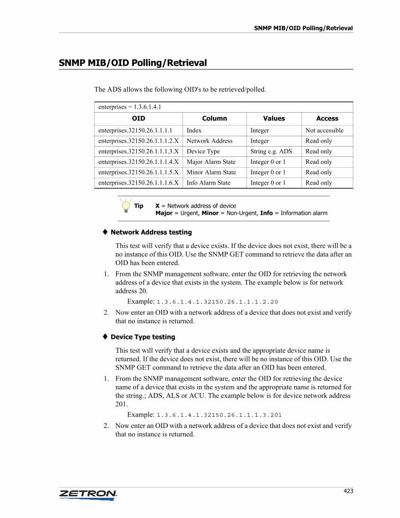
423
SNMP MIB/OID Polling/Retrieval
SNMP MIB/OID Polling/Retrieval
The ADS allows the following OID's to be retrieved/polled.
♦ Network Address testing
This test will verify that a device exists. If the device does not exist, there will be a no instance of this OID. Use the SNMP GET command to retrieve the data after an OID has been entered.
1. From the SNMP management software, enter the OID for retrieving the network address of a device that exists in the system. The example below is for network address 20.
Example: 1.3.6.1.4.1.32150.26.1.1.1.2.20
2. Now enter an OID with a network address of a device that does not exist and verify that no instance is returned.
♦ Device Type testing
This test will verify that a device exists and the appropriate device name is returned. If the device does not exist, there will be no instance of this OID. Use the SNMP GET command to retrieve the data after an OID has been entered.
1. From the SNMP management software, enter the OID for retrieving the device name of a device that exists in the system and the appropriate name is returned for the string.; ADS, ALS or ACU. The example below is for device network address 201.
Example: 1.3.6.1.4.1.32150.26.1.1.1.3.201
2. Now enter an OID with a network address of a device that does not exist and verify that no instance is returned.
enterprises = 1.3.6.1.4.1
OID Column Values Access
enterprises.32150.26.1.1.1.1 Index Integer Not accessible
enterprises.32150.26.1.1.1.2.X Network Address Integer Read only
enterprises.32150.26.1.1.1.3.X Device Type String e.g. ADS Read only
enterprises.32150.26.1.1.1.4.X Major Alarm State Integer 0 or 1 Read only
enterprises.32150.26.1.1.1.5.X Minor Alarm State Integer 0 or 1 Read only
enterprises.32150.26.1.1.1.6.X Info Alarm State Integer 0 or 1 Read only
Tip X = Network address of deviceMajor = Urgent, Minor = Non-Urgent, Info = Information alarm
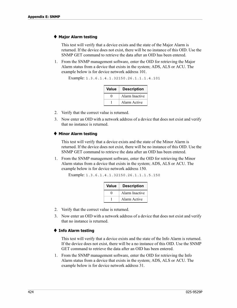
Appendix E: SNMP
424 025-9529P
♦ Major Alarm testing
This test will verify that a device exists and the state of the Major Alarm is returned. If the device does not exist, there will be no instance of this OID. Use the SNMP GET command to retrieve the data after an OID has been entered.
1. From the SNMP management software, enter the OID for retrieving the Major Alarm status from a device that exists in the system; ADS, ALS or ACU. The example below is for device network address 101.
Example: 1.3.6.1.4.1.32150.26.1.1.1.4.101
2. Verify that the correct value is returned.
3. Now enter an OID with a network address of a device that does not exist and verify that no instance is returned.
♦ Minor Alarm testing
This test will verify that a device exists and the state of the Minor Alarm is returned. If the device does not exist, there will be no instance of this OID. Use the SNMP GET command to retrieve the data after an OID has been entered.
1. From the SNMP management software, enter the OID for retrieving the Minor Alarm status from a device that exists in the system; ADS, ALS or ACU. The example below is for device network address 150.
Example: 1.3.6.1.4.1.32150.26.1.1.1.5.150
2. Verify that the correct value is returned.
3. Now enter an OID with a network address of a device that does not exist and verify that no instance is returned.
♦ Info Alarm testing
This test will verify that a device exists and the state of the Info Alarm is returned. If the device does not exist, there will be a no instance of this OID. Use the SNMP GET command to retrieve the data after an OID has been entered.
1. From the SNMP management software, enter the OID for retrieving the Info Alarm status from a device that exists in the system; ADS, ALS or ACU. The example below is for device network address 31.
Value Description
0 Alarm Inactive
1 Alarm Active
Value Description
0 Alarm Inactive
1 Alarm Active
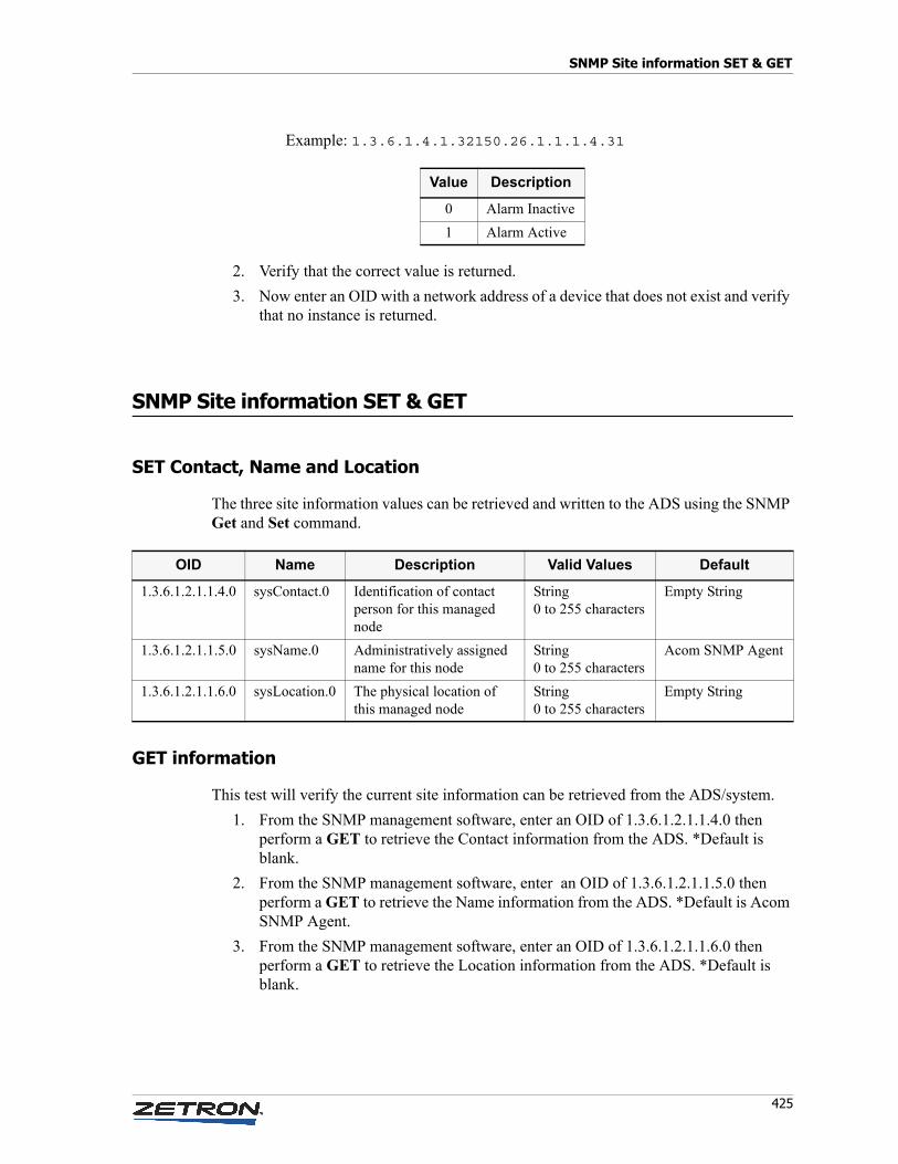
425
SNMP Site information SET & GET
Example: 1.3.6.1.4.1.32150.26.1.1.1.4.31
2. Verify that the correct value is returned.
3. Now enter an OID with a network address of a device that does not exist and verify that no instance is returned.
SNMP Site information SET & GET
SET Contact, Name and Location
The three site information values can be retrieved and written to the ADS using the SNMP Get and Set command.
GET information
This test will verify the current site information can be retrieved from the ADS/system.
1. From the SNMP management software, enter an OID of 1.3.6.1.2.1.1.4.0 then perform a GET to retrieve the Contact information from the ADS. *Default is blank.
2. From the SNMP management software, enter an OID of 1.3.6.1.2.1.1.5.0 then perform a GET to retrieve the Name information from the ADS. *Default is Acom SNMP Agent.
3. From the SNMP management software, enter an OID of 1.3.6.1.2.1.1.6.0 then perform a GET to retrieve the Location information from the ADS. *Default is blank.
Value Description
0 Alarm Inactive
1 Alarm Active
OID Name Description Valid Values Default
1.3.6.1.2.1.1.4.0 sysContact.0 Identification of contact person for this managed node
String0 to 255 characters
Empty String
1.3.6.1.2.1.1.5.0 sysName.0 Administratively assigned name for this node
String0 to 255 characters
Acom SNMP Agent
1.3.6.1.2.1.1.6.0 sysLocation.0 The physical location of this managed node
String0 to 255 characters
Empty String
Appendix E: SNMP
426 025-9529P
SET information
These tests verify that the site information can be written (SET) to the ADS/system.
CONTACT:
1. From the SNMP management software, enter an OID of 1.3.6.1.2.1.1.4.0 then perform a SET to write the Contact information to the ADS.
2. You should be prompted for the value for the Contact information.
3. Enter the desired text for the Contact information.
4. Once the Contact information has been written (SET), perform a GET on the Contact OID to verify that is has been set to the new value.
NAME:
1. From the SNMP management software, enter an OID of 1.3.6.1.2.1.1.5.0 then perform a SET to write the Name information to the ADS.
2. You should be prompted for the value for the Name information.
3. Enter the desired text for the Name information.
4. Once the Name information has been written (SET), perform a GET on the Name OID to verify that is has been set to the new value.
LOCATION:
1. From the SNMP management software, enter an OID of 1.3.6.1.2.1.1.6.0 then perform a SET to write the Location information to the ADS.
2. You should be prompted for the value for the Location information.
3. Enter the desired text for the Location information.
4. Once the Location information has been written (SET), perform a GET on the Location OID to verify that is has been set to the new value.
Troubleshooting
• Check ADS SNMP settings for proper Community and IP Address
• Make sure ADS can be pinged from the SNMP management PC using the windows ping.exe program
• Check Ethernet cable connection to ADS
• Verify that the SNMP management software has the correct settings for Port (typically 161), SNMP version 2c, and Community and Agent IP Addresses
Overview
427
Appendix F: Intersite Bearers
Overview
Introduction
Intersite bearers (ISBs) provide a means of interconnecting two or more Acom sites, to provide remote operation. ISB connections are implemented between ADSes at separate Acom sites, by way of E1 or T1 connections on the MCU4 cards. This enables the appearance of a single Acom system. Radio and phone lines at one site can be used for both incoming and outgoing calls by operators at any connected site. Remote consoles can be included in conferences and patches, just as if they were local. The following figure represents a multisite layout. Each rectangle represents a site.
Every bearer has an incoming and an outgoing side. That is, one MCU4 port must be configured as an incoming bearer, and the mating MCU4 port on the other site must be configured as an outgoing bearer. In a bearer group containing a main and a standby link, the outgoing side determines the link to use. In this sense the outgoing side of any bearer connection can be considered the controller of the main/standby changeover decisions.
In the following figure, Site C is connected to Site A or Site B, depending on which link is active. The MCU4 at Site C has been configured as the outgoing link and therefore determines whether the main or standby link is active. Basically, if Site C determines that the main link to Site A is not functioning properly, it will automatically enable the standby link that is connected to Site B to establish communication through that link and restore system functionality.
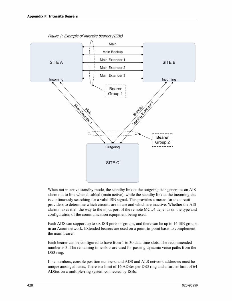
Appendix F: Intersite Bearers
428 025-9529P
Figure 1: Example of intersite bearers (ISBs)
When not in active standby mode, the standby link at the outgoing side generates an AIS alarm out to line when disabled (main active), while the standby link at the incoming site is continuously searching for a valid ISB signal. This provides a means for the circuit providers to determine which circuits are in use and which are inactive. Whether the AIS alarm makes it all the way to the input port of the remote MCU4 depends on the type and configuration of the communication equipment being used.
Each ADS can support up to six ISB ports or groups, and there can be up to 14 ISB groups in an Acom network. Extended bearers are used on a point-to-point basis to complement the main bearer.
Each bearer can be configured to have from 1 to 30 data time slots. The recommended number is 3. The remaining time slots are used for passing dynamic voice paths from the DS3 ring.
Line numbers, console position numbers, and ADS and ALS network addresses must be unique among all sites. There is a limit of 16 ADSes per DS3 ring and a further limit of 64 ADSes on a multiple-ring system connected by ISBs.
SITE C
SITE A SITE B
Main Extender 1
Stand
by E
xten
der 1
Main
Main Backup
Main Extender 1
Main Extender 2
Main Extender 3Incoming
Outgoing
Incoming
Main
Stand
byBearer
Group 2
Bearer Group 1
429
Overview
The system automatically exchanges relevant data between the local and remote ADS as bearers come online. All ADSes at all connected sites synchronize required line and operator information with each other. When an ISB goes offline, the line and operator information associated with it is removed from all ADSes at all sites.
When an operator selects a line located across an ISB, the operator’s audio time slot is read from the DS3 backbone, sent over the bearer, and written to the corresponding location on the remote DS3 backbone. This “copying” process is applied to any connection allocated dynamically between a local and a remote time slot. A time slot is “copied” between the local and remote systems only once, no matter how many other lines or operators are connected to it.
When an operator at one site selects a line that is physically at another site, they may notice a slight delay before the line becomes selected, compared to if the line were local.
When there are two permanently allocated ISBs between sites, one link is used before the second until capacity on the first is reached.
Capabilities
The following features are supported over ISBs:
Feature Notes
Access and control Acom digital IO over ISBs
(By configuration)
Access to consoles Configurable as not replicated over ISB or over all ISBs. Further granularity allows the audio replication to be permanent or dynamic.
Access to line Configurable as not replicated over ISB or over all ISBs. Further granularity allows the audio replication to be permanent or dynamic.
Call System —
Console connections supported Group (line receive audio only), conference, patch.
Console intrudes —
Console transfer of line to other console
—
Group listen to a remote line’s transmit audio
—
Instant transmit Instant transmits may have performance issues. See Performance Limitations on page 430.
Intercoms Includes both global and broadcast intercoms
Log a remote line’s transmit audio —
Logging lines or consoles Line/console must be replicated, logs line/console receive audio only, permanently uses a TS over ISB.
Miscellaneous Line Control Channel change, holds, various attenuation/volumes, vox control, malicious call control, hook flash, voting, execute functions, muting
Appendix F: Intersite Bearers
430 025-9529P
Feature Limitations
The following features are not supported over ISBs:
• ACD functions
• Console-initiated line transfers
• Fixed connections
• Line-to-line autocalls
• NMS events do not traverse ISBs(wide-area networking of NMS is typically provided external to the Acom system)
• Paging or dialing work groups
• System tones (other than ring tones)
• Utility audio
Performance Limitations
ISBs do not provide the same system messaging bandwidth as the DS3 backbone. ISB limitation currently is about 4x64kb, the DS3 backbone is 2Mb. Although this is configurable, and may be a low as 1x64kb.
Time to feed objects (lines/consoles).
Monitor a remote line’s transmit audio
—
Monitoring remote lines Line must be replicated, monitors line receive audio only, permanently uses a TS over ISB.
Opensky lines —
P25 DFSI and CSSI
PTTs either line to line, console to line, or line to console, in groups, conferences, patches
This includes PTT blocking, priority overrides, console cross mutes, line cross mutes.
Radio & phone dialing or paging —
Radio & phone receiving dials CLI, ISDN, Selcal, MDC1200
Real Time Clock Supports daylight savings shifts per site, time zone offsets per site, a master clock hierarchy (multiple clock source sites, multiple clock sources per site, site master, system master). The ability to source a clock at a site without an ALS, ie. direct connect to ADS via serial port or Ethernet NTP.
SNMP —
Source ring tone Configurable per individual bearer group.
System alarms Configurable as not passed over ISB or over all ISBs.
Work groups, connections, and PTTs —
Feature Notes
431
Operation
ISB changeovers are seamless, however after a changeover it takes a period for the redundancy state to be fed and backed up. A subsequent changeover during this period, before feed is complete, results in a disestablishment of the ISB. All remote lines, consoles, connections, etc., are lost.
Because the establishment of audio TS allocations over an ISB requires a series of message flows at different layers, audio TS allocations are typically set up when a console connection is first established. For instant transmits there is no guaranteed prior knowledge of the need for the console audio to be replicated to the lines site, therefore the audio TS allocation process does not begin until the PTT is active. As a result, the line will be keyed prior to any console audio allocation and until the allocation is complete, there is an indication to the console operator that the audio replication is failed. This delay would increase over multiple ISB hops, such as when 3 or more sites are joined in series by ISBs. These issues can be avoided by permanently replicating a console’s audio. This same principle applies to logging, monitoring, or group listening of a line’s transmit audio over an ISB.
Transmit audio sources can very quickly exhaust ISB audio capacity, particularly in multi-hop ISB systems. It is important to understand this when configuring channels to be replicated, and allowing tx on monitor/group, or assigning remote loggers with both rx/tx audio enabled.
Replicating lines will flood ISBs in a system, ie if a line is in an active connection it's audio is activated on all ISBs. For this reason lines should typically be configured for dynamic ISB replication. Of course there will be customer requirements for permanent replication, in which case the allocation of ISBs needs to take this into consideration.
Consoles are only ever permanently replicated, so their audio is always activated over ISBs. However, using Profile Management, the ISBs a console is permanently replicated over can be configured, ie no flooding like lines.
Operation
To a console operator, using resources from remote sites is relatively similar to using local resources. There may be lessened responsiveness in the event of heavy usage of remote resources if inappropriate data capacity has been configured for an ISB. In the event of complete failure of an ISB, the resources will become unavailable and related buttons are disabled. In the event the audio capacity for an ISB is exhausted (due to overuse of the configured capacity or failed links reducing the capacity) the operator is notified by indicators on resource buttons of failed audio, the indication is for failed audio in either direction. There are alarms, fault logs, and resource level indications to operators and maintenance staff to determine the state and performance of ISBs.
Appendix F: Intersite Bearers
432 025-9529P
Architecture
An ISB group comprises one or more ISB links, with each link requiring an MCU4 E1/T1 port at both ends configured as an ISB port. Each ADS may contain up to 6 ISB ports. An Acom system can have up to 14 ISB links, ie 15 sites. The network layout of ISB interconnected sites must not contain loops, ie it is a star/hub topology. Each site may have one or more ADS. The ISB ports and any connected ACUs or ALSs can be distributed arbitrarily amongst the ADSs at a site, although there are constraints or recommendations to be followed to improve redundancy and in certain cases performance. Every ISB port has a configurable allocation of timeslots to be used for data and audio. This is highly configurable allowing complex shared or leased E1/T1 line usage, ie where only a specific subset of the E1/T1 links timeslot's are available to the user.
(General paragraphs that applies to all ISB ports)
For an ISB port to operate it firstly must be configured correctly, and it must be connected over a link to another ISB port with correct settings. The ports at either end must have matching ISB port type, ISB group number, and data timeslot allocations. Additionally one end must be defined as outgoing and the other as incoming, this is not related to location of resources and is only important for certain redundancy layouts described later. Typically audio timeslot allocations will be the same at either port, although not necessary. It is possible to have different allocations at either end, when this is the case the configuration refers to what timeslots this ADS will transmit audio on.
Furthermore for an ISB port to operate requires that there are no errors present on the E1 link, eg LOS, LOF, AIS. When a fault is present the port is disabled. The Acom also provides the ability to disable ISB ports based on longer term stability. The stability system monitors the number of events over a long period, if the events exceed a threshold the port is disabled. Similarly once a port is disabled, events are monitored over a long period, if the events remain under a threshold the port is enabled. Using the stability system is a configurable option, and it has configurable settings for the periods and thresholds and events to monitor.
(Now get specific, but start with simpler scenarios and work your way up)
As mentioned an ISB group comprises one or more ISB links and the associated ports. There are several types of ISB port types that can be used to make up an ISB group. The choice of these types is dictated by what if any redundancy is required.
The simplest ISB group has no redundancy. This simple ISB group at a minimum must have a Main ISB link. The Main ISB link is the first building block of any ISB group, with or without redundancy. The Main ISB ports (at either end of the link) are the controllers for an ISB group, they are in control of all audio allocations as well as access to remote resources. As the controller of an ISB group the Main ISB port allows configuration of one or more data timeslots, these are needed for messaging and data transfer that allows the controller to function. The number of data timeslots needed varies with the system size and layout, but typically 3 is a recommended minimum. The remaining timeslots can be configured for audio timeslots. An ISB group can only have a single Main link. When
433
Redundancy
more audio capacity is required than can be provided with a single Main ISB port the Acom provides Main Extender ports. Main extender ports are used to extend the audio capacity for the Main ISB group. An extender port requires a single data timeslot for the transfer of minimal data needed for end-to-end link establishment, the remaining timeslots are available for audio. The audio capacity of a Main ISB group can be further expanded by configuring multiple Main extender ports, up to 8 in total.
In this non-redundant layout if the Main ISB port is disabled or there is an equipment failure within the ADS the ISB group fails, as the Main ISB port and ADS control the ISB group. A failed ISB group means any remote resources accessed over that ISB are no longer available, eg calls to remote lines at that time are lost. When an extender port is disabled or suffers an equipment failure the ISB group still functions, however any active audio over the extender port will be lost and there will be reduced audio capacity. Depending on the remaining audio capacity the lost audio may remain unavailable for a period of time.
Redundancy
The Acom provides two types of redundancy for ISBs, one for equipment or individual port/link failures and another for E1/T1 path failures external to the Acom. These 2 types of redundancy have very different behavior and configuration.
Equipment Redundancy
For equipment redundancy an ISB group will have a Main Backup ISB link, like Main ISB links an ISB group can only have a single Main Backup link. The Main Backup port must be configured on another ADS at the site, ie it cannot be configured on the same ADS as the Main ISB port. The Main Backup port like the Main port will require data timeslots to be configured, typically these should be the same for both Main and Backup. During normal operation the Main Backup port is enabled and is ready to takeover control in the event of a Main link failure, essentially a hot-standby. If the Main link or any equipment at either end of the Main link fails the Main Backup will takeover control seamlessly. There will be no loss of remote resources. Of course the failure of the Main link will inherently result in a reduction of audio capacity, depending on the remaining audio capacity there may be lost audio for a period of time. If the failure is rectified the Main Backup port will retain control, and the Main port will then be available for audio. The Main port will take on the hot-redundancy backup role, any subsequent failure of the Main backup link causing another changeover back to the Main port. There are no limits to the number of these changeovers, but there are limitations on the frequency due to the time it takes an enabled Main or Main Backup port to synchronize itself with the ISB groups current state. This period is dependent on the system layout and usage levels, for small quiet systems a few seconds, for large busy systems it may take 10s of seconds even minutes. If a failure occurs during this period the ISB group fails and any remote resources accessed over that ISB are no longer available, eg calls to remote lines at that time are lost.
Appendix F: Intersite Bearers
434 025-9529P
During normal operation if the Main Backup port is enabled its audio capacity is available and will be used similarly to an extender port. A Main backup port need not be in control for its audio capacity to be used. Because of this it would be unusual for an ISB group to have extender ports without a backup port, ie a backup port provides extended audio capacity (minus a few additional timeslots used for data) with the additional benefit of redundancy. The only occasions this would not be the case is if there is an extreme shortage of audio capacity and the few additional data timeslots becomes an issue, or if a site has only a single ADS (main and backup ports are not allowed on same ADS).
Path Redundancy
Path redundancy will typically be used in cases where the E1/T1 links that comprise an ISB group and join 2 sites are vulnerable to single point failure, eg if they are all carried over a single higher capacity bearer such as E3 or optical fibres. This type of single failure outside of the Acom can not be guarded against using the above equipment redundancy model. The Acom provides path redundancy with standby ISB groups. For a standby ISB group to provide path redundancy its ISB links must be carried over a separate medium than the main ISB group. For systems that have more than 2 sites the standby ISB links typically go to another site than the main ISB group. This is not necessary, and in some cases the main and standby ISB groups terminate at the same sites. An important difference between equipment redundancy and path redundancy is that path redundancy is not hot-standby. A changeover between main and standby ISB groups is not seamless, there will be a momentary loss of remote resources and calls, and it will take a period for standby group to build up during which the remote resources are not available. This is necessary to allow path redundancy to terminate at different sites. For path redundancy this is generally acceptable as this type of event is cataclysmic, eg disaster recovery. It is also possible for standby ISB groups to be carried over dial-up or on demand links, in which case it would be impractical and expensive for the standby groups to be hot-standby.
Path redundancy is achieved by configuring Standby ISB ports. Standby ISB ports are similar to Main ISB ports. A standby ISB group, similar to a Main ISB group may also comprise multiple extenders, configured as Standby Extender ports. A standby ISB group, similar to a Main ISB group may also comprise a backup port, configured as Standby Backup port. Generally Main/Standby group changeover decisions are based on available audio capacity. As individual ports fail or groups of ports fail the collective audio capacity in both directions of the Main ISB group is compared to that of the Standby ISB group. The group with the highest capacity is chosen. There is a case where the group capacity decision is overruled, that is when due to link failures a Main/Standby ISB group has no port capable of controlling such as a Main or Main Backup port (alternatively Standby or Standby Backup port). Due to the nature of main/standby changeovers resulting in temporary loss of remote resources it is desirable to prevent frequent changeovers in the case of intermittent links. This is where the stability monitoring system described above is most useful.
Once a Standby ISB group has been chosen and is operational then its backup and extender links behave identical to that of the Main ISB group.
435
Maintenance
Standby ISB groups can be configured to be active standby or not. This is not hot-standby. An active standby ISB group is typically used when the links are always available. A non-active standby ISB group is used when the group is carried over dial-up or on demand links. Non-active standby is different because there is no way to determine the availability of the links until they are established. The Acom makes its main/standby ISB group changeover decisions based on assumed capacity, ie it assumes all the standby group ISB ports are going to be Ok and there full capacity in both directions is available.
Finally standby ISB ports use the outgoing/incoming direction for determining the controlling end of the standby group. The outgoing end is in control of main/standby changeover decisions. The decision has to be made by one end alone, this is necessary to support the in-active standby configuration. Another reason is to support the case where the standby group terminates at a different site to the main group, in which case only the site where both groups terminate has the ability to monitor the state of both the main and standby group. The outgoing site is responsible for disabling in-active standby groups by transmitting AIS on its ports.
Maintenance
Configuration, alarms, fault logs, and comprehensive status is available for ISBs using IMS. ADS LEDs also provide a summary of the status of the individual ISB ports and also the status of the ISB group the port belongs to.

Appendix F: Intersite Bearers
436 025-9529P
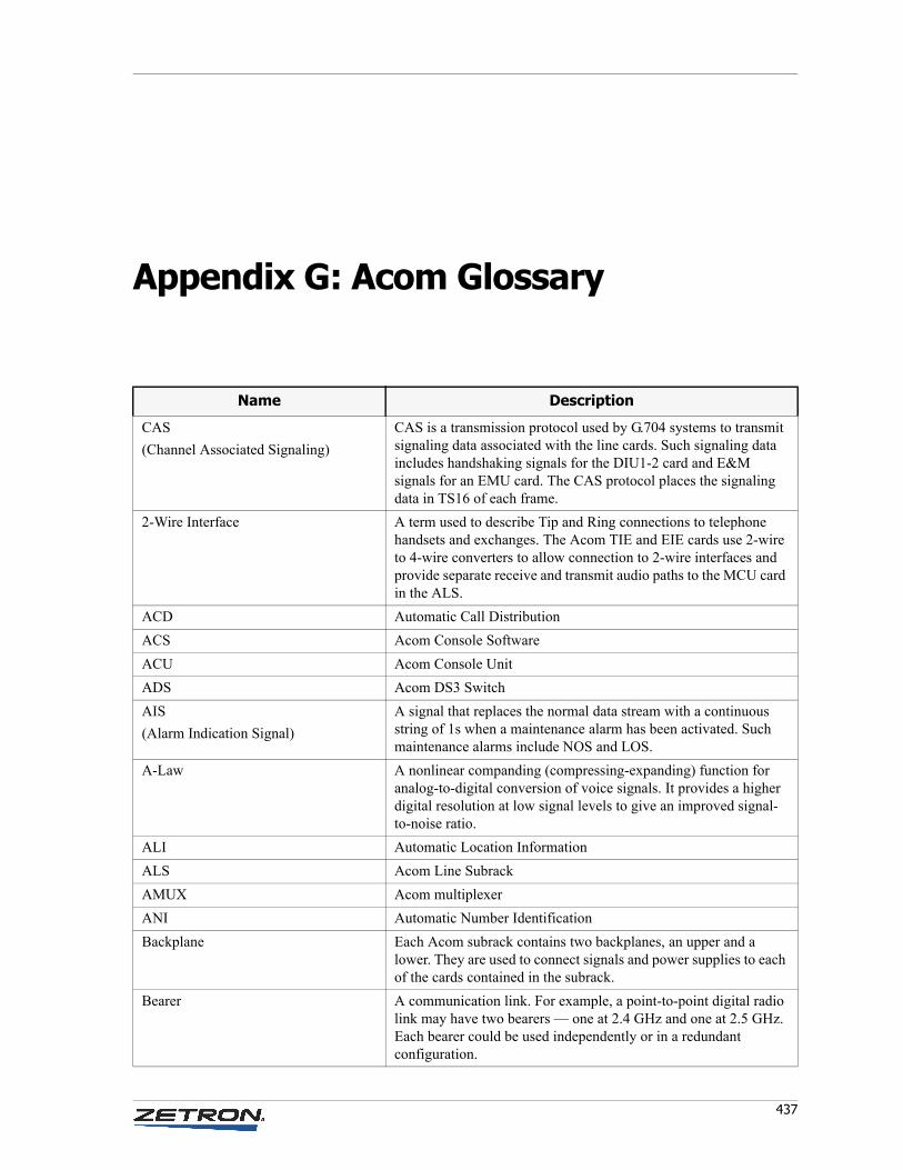
437
Appendix G: Acom Glossary
Name Description
CAS
(Channel Associated Signaling)
CAS is a transmission protocol used by G.704 systems to transmit signaling data associated with the line cards. Such signaling data includes handshaking signals for the DIU1-2 card and E&M signals for an EMU card. The CAS protocol places the signaling data in TS16 of each frame.
2-Wire Interface A term used to describe Tip and Ring connections to telephone handsets and exchanges. The Acom TIE and EIE cards use 2-wire to 4-wire converters to allow connection to 2-wire interfaces and provide separate receive and transmit audio paths to the MCU card in the ALS.
ACD Automatic Call Distribution
ACS Acom Console Software
ACU Acom Console Unit
ADS Acom DS3 Switch
AIS
(Alarm Indication Signal)
A signal that replaces the normal data stream with a continuous string of 1s when a maintenance alarm has been activated. Such maintenance alarms include NOS and LOS.
A-Law A nonlinear companding (compressing-expanding) function for analog-to-digital conversion of voice signals. It provides a higher digital resolution at low signal levels to give an improved signal-to-noise ratio.
ALI Automatic Location Information
ALS Acom Line Subrack
AMUX Acom multiplexer
ANI Automatic Number Identification
Backplane Each Acom subrack contains two backplanes, an upper and a lower. They are used to connect signals and power supplies to each of the cards contained in the subrack.
Bearer A communication link. For example, a point-to-point digital radio link may have two bearers — one at 2.4 GHz and one at 2.5 GHz. Each bearer could be used independently or in a redundant configuration.
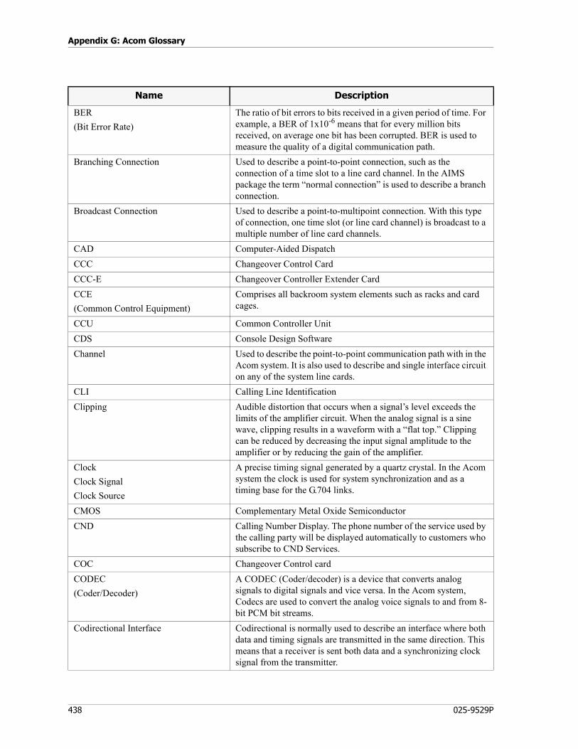
Appendix G: Acom Glossary
438 025-9529P
BER
(Bit Error Rate)
The ratio of bit errors to bits received in a given period of time. For example, a BER of 1x10⁻⁶ means that for every million bits received, on average one bit has been corrupted. BER is used to measure the quality of a digital communication path.
Branching Connection Used to describe a point-to-point connection, such as the connection of a time slot to a line card channel. In the AIMS package the term “normal connection” is used to describe a branch connection.
Broadcast Connection Used to describe a point-to-multipoint connection. With this type of connection, one time slot (or line card channel) is broadcast to a multiple number of line card channels.
CAD Computer-Aided Dispatch
CCC Changeover Control Card
CCC-E Changeover Controller Extender Card
CCE
(Common Control Equipment)
Comprises all backroom system elements such as racks and card cages.
CCU Common Controller Unit
CDS Console Design Software
Channel Used to describe the point-to-point communication path with in the Acom system. It is also used to describe and single interface circuit on any of the system line cards.
CLI Calling Line Identification
Clipping Audible distortion that occurs when a signal’s level exceeds the limits of the amplifier circuit. When the analog signal is a sine wave, clipping results in a waveform with a “flat top.” Clipping can be reduced by decreasing the input signal amplitude to the amplifier or by reducing the gain of the amplifier.
Clock
Clock Signal
Clock Source
A precise timing signal generated by a quartz crystal. In the Acom system the clock is used for system synchronization and as a timing base for the G.704 links.
CMOS Complementary Metal Oxide Semiconductor
CND Calling Number Display. The phone number of the service used by the calling party will be displayed automatically to customers who subscribe to CND Services.
COC Changeover Control card
CODEC
(Coder/Decoder)
A CODEC (Coder/decoder) is a device that converts analog signals to digital signals and vice versa. In the Acom system, Codecs are used to convert the analog voice signals to and from 8-bit PCM bit streams.
Codirectional Interface Codirectional is normally used to describe an interface where both data and timing signals are transmitted in the same direction. This means that a receiver is sent both data and a synchronizing clock signal from the transmitter.
Name Description
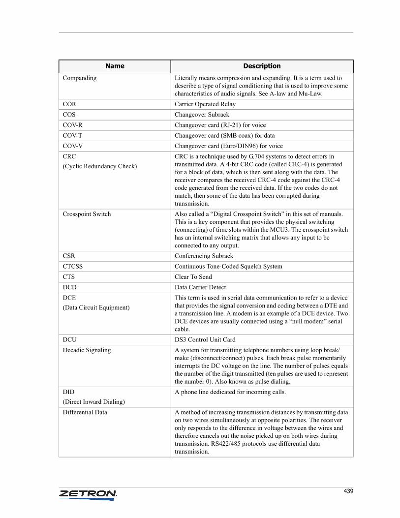
439
Companding Literally means compression and expanding. It is a term used to describe a type of signal conditioning that is used to improve some characteristics of audio signals. See A-law and Mu-Law.
COR Carrier Operated Relay
COS Changeover Subrack
COV-R Changeover card (RJ-21) for voice
COV-T Changeover card (SMB coax) for data
COV-V Changeover card (Euro/DIN96) for voice
CRC
(Cyclic Redundancy Check)
CRC is a technique used by G.704 systems to detect errors in transmitted data. A 4-bit CRC code (called CRC-4) is generated for a block of data, which is then sent along with the data. The receiver compares the received CRC-4 code against the CRC-4 code generated from the received data. If the two codes do not match, then some of the data has been corrupted during transmission.
Crosspoint Switch Also called a “Digital Crosspoint Switch” in this set of manuals. This is a key component that provides the physical switching (connecting) of time slots within the MCU3. The crosspoint switch has an internal switching matrix that allows any input to be connected to any output.
CSR Conferencing Subrack
CTCSS Continuous Tone-Coded Squelch System
CTS Clear To Send
DCD Data Carrier Detect
DCE
(Data Circuit Equipment)
This term is used in serial data communication to refer to a device that provides the signal conversion and coding between a DTE and a transmission line. A modem is an example of a DCE device. Two DCE devices are usually connected using a “null modem” serial cable.
DCU DS3 Control Unit Card
Decadic Signaling A system for transmitting telephone numbers using loop break/make (disconnect/connect) pulses. Each break pulse momentarily interrupts the DC voltage on the line. The number of pulses equals the number of the digit transmitted (ten pulses are used to represent the number 0). Also known as pulse dialing.
DID
(Direct Inward Dialing)
A phone line dedicated for incoming calls.
Differential Data A method of increasing transmission distances by transmitting data on two wires simultaneously at opposite polarities. The receiver only responds to the difference in voltage between the wires and therefore cancels out the noise picked up on both wires during transmission. RS422/485 protocols use differential data transmission.
Name Description
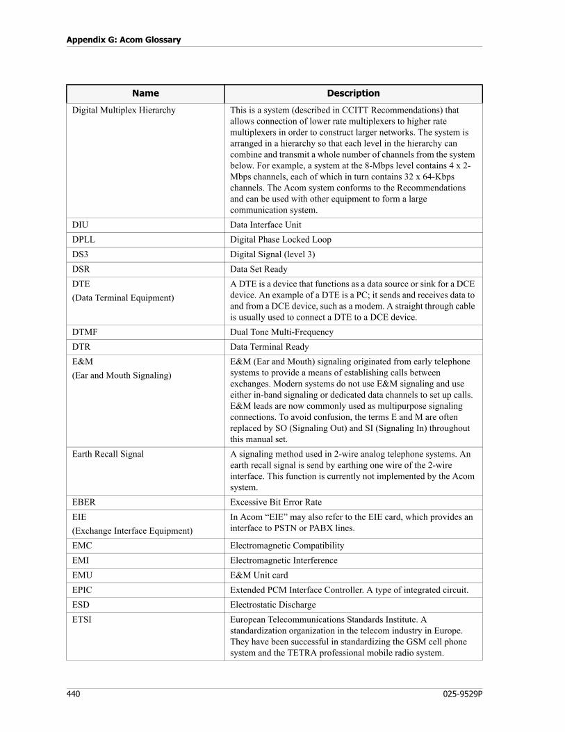
Appendix G: Acom Glossary
440 025-9529P
Digital Multiplex Hierarchy This is a system (described in CCITT Recommendations) that allows connection of lower rate multiplexers to higher rate multiplexers in order to construct larger networks. The system is arranged in a hierarchy so that each level in the hierarchy can combine and transmit a whole number of channels from the system below. For example, a system at the 8-Mbps level contains 4 x 2-Mbps channels, each of which in turn contains 32 x 64-Kbps channels. The Acom system conforms to the Recommendations and can be used with other equipment to form a large communication system.
DIU Data Interface Unit
DPLL Digital Phase Locked Loop
DS3 Digital Signal (level 3)
DSR Data Set Ready
DTE
(Data Terminal Equipment)
A DTE is a device that functions as a data source or sink for a DCE device. An example of a DTE is a PC; it sends and receives data to and from a DCE device, such as a modem. A straight through cable is usually used to connect a DTE to a DCE device.
DTMF Dual Tone Multi-Frequency
DTR Data Terminal Ready
E&M
(Ear and Mouth Signaling)
E&M (Ear and Mouth) signaling originated from early telephone systems to provide a means of establishing calls between exchanges. Modern systems do not use E&M signaling and use either in-band signaling or dedicated data channels to set up calls. E&M leads are now commonly used as multipurpose signaling connections. To avoid confusion, the terms E and M are often replaced by SO (Signaling Out) and SI (Signaling In) throughout this manual set.
Earth Recall Signal A signaling method used in 2-wire analog telephone systems. An earth recall signal is send by earthing one wire of the 2-wire interface. This function is currently not implemented by the Acom system.
EBER Excessive Bit Error Rate
EIE
(Exchange Interface Equipment)
In Acom “EIE” may also refer to the EIE card, which provides an interface to PSTN or PABX lines.
EMC Electromagnetic Compatibility
EMI Electromagnetic Interference
EMU E&M Unit card
EPIC Extended PCM Interface Controller. A type of integrated circuit.
ESD Electrostatic Discharge
ETSI European Telecommunications Standards Institute. A standardization organization in the telecom industry in Europe. They have been successful in standardizing the GSM cell phone system and the TETRA professional mobile radio system.
Name Description
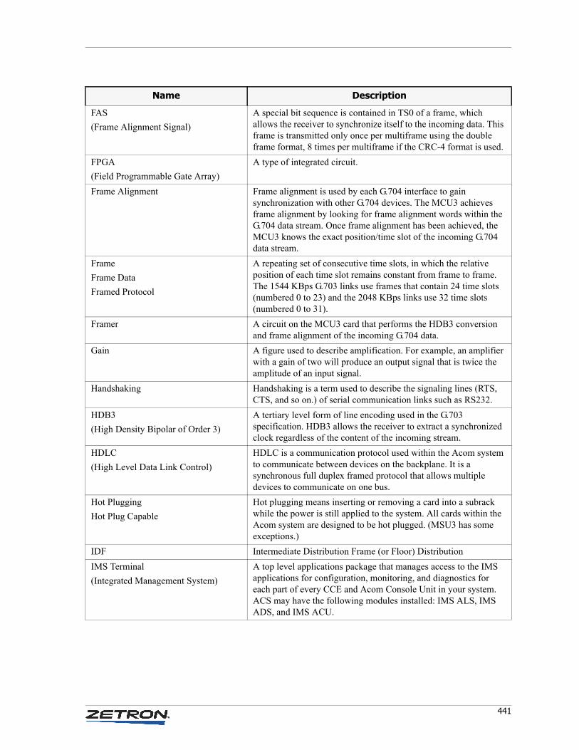
441
FAS
(Frame Alignment Signal)
A special bit sequence is contained in TS0 of a frame, which allows the receiver to synchronize itself to the incoming data. This frame is transmitted only once per multiframe using the double frame format, 8 times per multiframe if the CRC-4 format is used.
FPGA
(Field Programmable Gate Array)
A type of integrated circuit.
Frame Alignment Frame alignment is used by each G.704 interface to gain synchronization with other G.704 devices. The MCU3 achieves frame alignment by looking for frame alignment words within the G.704 data stream. Once frame alignment has been achieved, the MCU3 knows the exact position/time slot of the incoming G.704 data stream.
Frame
Frame Data
Framed Protocol
A repeating set of consecutive time slots, in which the relative position of each time slot remains constant from frame to frame. The 1544 KBps G.703 links use frames that contain 24 time slots (numbered 0 to 23) and the 2048 KBps links use 32 time slots (numbered 0 to 31).
Framer A circuit on the MCU3 card that performs the HDB3 conversion and frame alignment of the incoming G.704 data.
Gain A figure used to describe amplification. For example, an amplifier with a gain of two will produce an output signal that is twice the amplitude of an input signal.
Handshaking Handshaking is a term used to describe the signaling lines (RTS, CTS, and so on.) of serial communication links such as RS232.
HDB3
(High Density Bipolar of Order 3)
A tertiary level form of line encoding used in the G.703 specification. HDB3 allows the receiver to extract a synchronized clock regardless of the content of the incoming stream.
HDLC
(High Level Data Link Control)
HDLC is a communication protocol used within the Acom system to communicate between devices on the backplane. It is a synchronous full duplex framed protocol that allows multiple devices to communicate on one bus.
Hot Plugging
Hot Plug Capable
Hot plugging means inserting or removing a card into a subrack while the power is still applied to the system. All cards within the Acom system are designed to be hot plugged. (MSU3 has some exceptions.)
IDF Intermediate Distribution Frame (or Floor) Distribution
IMS Terminal
(Integrated Management System)
A top level applications package that manages access to the IMS applications for configuration, monitoring, and diagnostics for each part of every CCE and Acom Console Unit in your system. ACS may have the following modules installed: IMS ALS, IMS ADS, and IMS ACU.
Name Description
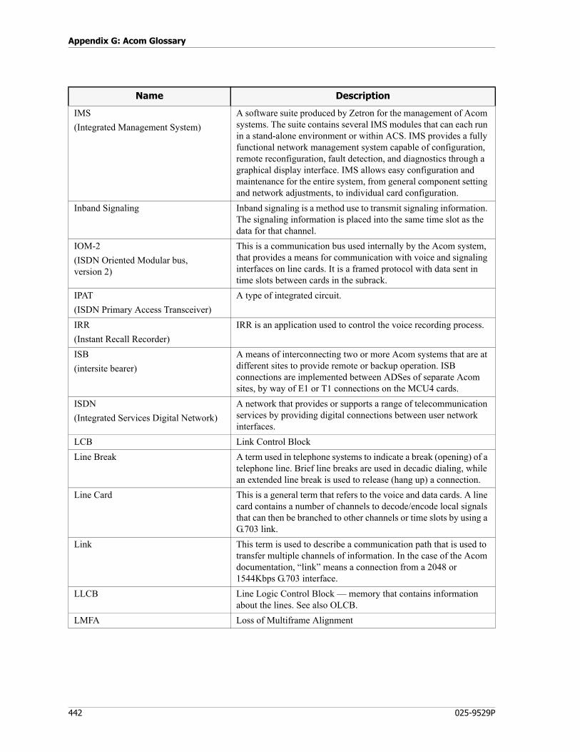
Appendix G: Acom Glossary
442 025-9529P
IMS
(Integrated Management System)
A software suite produced by Zetron for the management of Acom systems. The suite contains several IMS modules that can each run in a stand-alone environment or within ACS. IMS provides a fully functional network management system capable of configuration, remote reconfiguration, fault detection, and diagnostics through a graphical display interface. IMS allows easy configuration and maintenance for the entire system, from general component setting and network adjustments, to individual card configuration.
Inband Signaling Inband signaling is a method use to transmit signaling information. The signaling information is placed into the same time slot as the data for that channel.
IOM-2
(ISDN Oriented Modular bus,version 2)
This is a communication bus used internally by the Acom system, that provides a means for communication with voice and signaling interfaces on line cards. It is a framed protocol with data sent in time slots between cards in the subrack.
IPAT
(ISDN Primary Access Transceiver)
A type of integrated circuit.
IRR
(Instant Recall Recorder)
IRR is an application used to control the voice recording process.
ISB
(intersite bearer)
A means of interconnecting two or more Acom systems that are at different sites to provide remote or backup operation. ISB connections are implemented between ADSes of separate Acom sites, by way of E1 or T1 connections on the MCU4 cards.
ISDN
(Integrated Services Digital Network)
A network that provides or supports a range of telecommunication services by providing digital connections between user network interfaces.
LCB Link Control Block
Line Break A term used in telephone systems to indicate a break (opening) of a telephone line. Brief line breaks are used in decadic dialing, while an extended line break is used to release (hang up) a connection.
Line Card This is a general term that refers to the voice and data cards. A line card contains a number of channels to decode/encode local signals that can then be branched to other channels or time slots by using a G.703 link.
Link This term is used to describe a communication path that is used to transfer multiple channels of information. In the case of the Acom documentation, “link” means a connection from a 2048 or 1544Kbps G.703 interface.
LLCB Line Logic Control Block — memory that contains information about the lines. See also OLCB.
LMFA Loss of Multiframe Alignment
Name Description
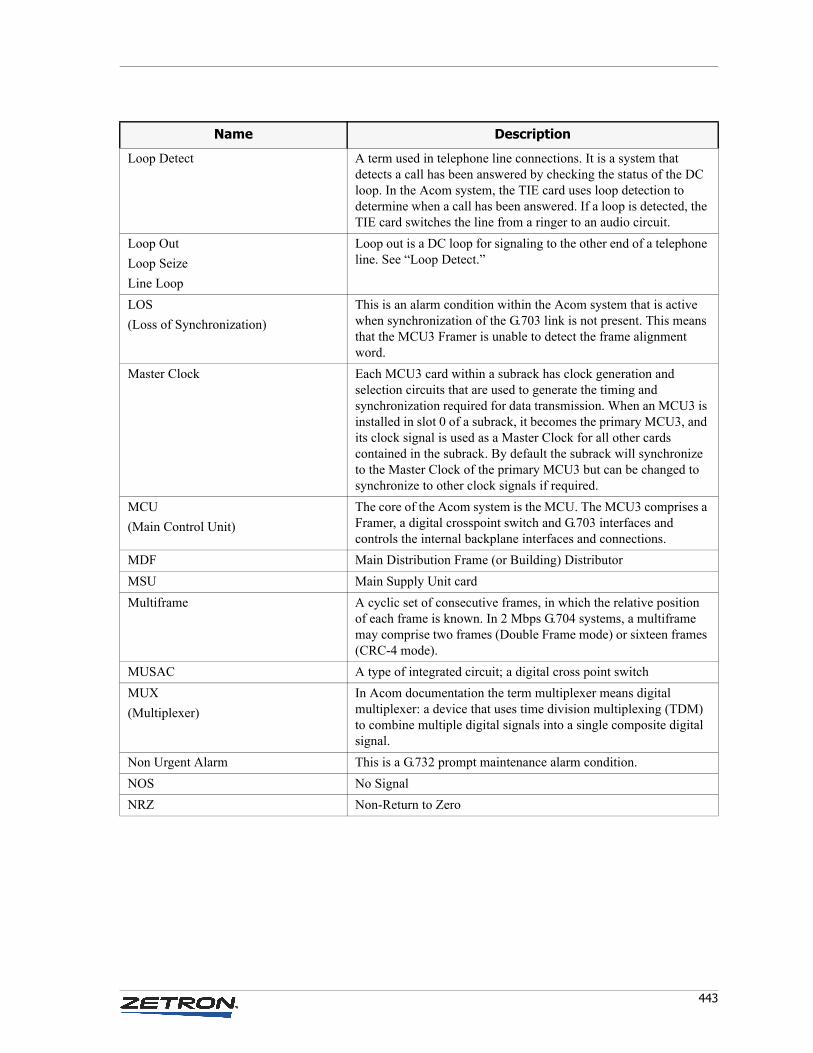
443
Loop Detect A term used in telephone line connections. It is a system that detects a call has been answered by checking the status of the DC loop. In the Acom system, the TIE card uses loop detection to determine when a call has been answered. If a loop is detected, the TIE card switches the line from a ringer to an audio circuit.
Loop Out
Loop Seize
Line Loop
Loop out is a DC loop for signaling to the other end of a telephone line. See “Loop Detect.”
LOS
(Loss of Synchronization)
This is an alarm condition within the Acom system that is active when synchronization of the G.703 link is not present. This means that the MCU3 Framer is unable to detect the frame alignment word.
Master Clock Each MCU3 card within a subrack has clock generation and selection circuits that are used to generate the timing and synchronization required for data transmission. When an MCU3 is installed in slot 0 of a subrack, it becomes the primary MCU3, and its clock signal is used as a Master Clock for all other cards contained in the subrack. By default the subrack will synchronize to the Master Clock of the primary MCU3 but can be changed to synchronize to other clock signals if required.
MCU
(Main Control Unit)
The core of the Acom system is the MCU. The MCU3 comprises a Framer, a digital crosspoint switch and G.703 interfaces and controls the internal backplane interfaces and connections.
MDF Main Distribution Frame (or Building) Distributor
MSU Main Supply Unit card
Multiframe A cyclic set of consecutive frames, in which the relative position of each frame is known. In 2 Mbps G.704 systems, a multiframe may comprise two frames (Double Frame mode) or sixteen frames (CRC-4 mode).
MUSAC A type of integrated circuit; a digital cross point switch
MUX
(Multiplexer)
In Acom documentation the term multiplexer means digital multiplexer: a device that uses time division multiplexing (TDM) to combine multiple digital signals into a single composite digital signal.
Non Urgent Alarm This is a G.732 prompt maintenance alarm condition.
NOS No Signal
NRZ Non-Return to Zero
Name Description
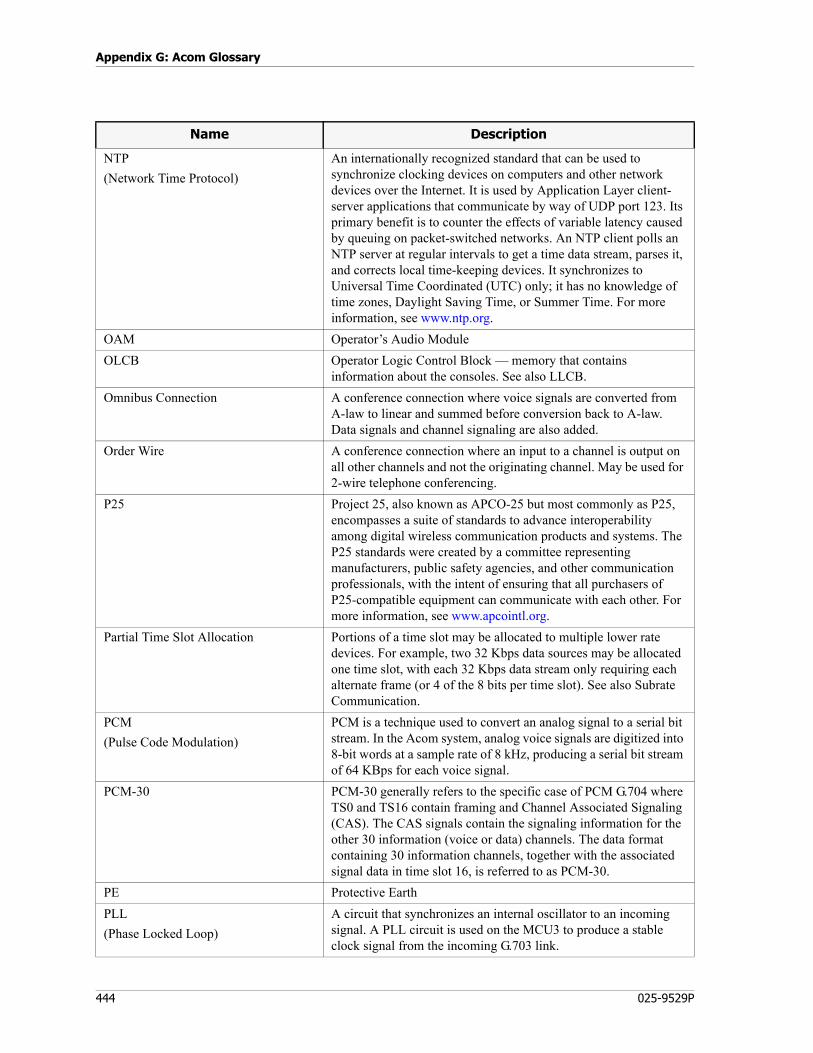
Appendix G: Acom Glossary
444 025-9529P
NTP
(Network Time Protocol)
An internationally recognized standard that can be used to synchronize clocking devices on computers and other network devices over the Internet. It is used by Application Layer client-server applications that communicate by way of UDP port 123. Its primary benefit is to counter the effects of variable latency caused by queuing on packet-switched networks. An NTP client polls an NTP server at regular intervals to get a time data stream, parses it, and corrects local time-keeping devices. It synchronizes to Universal Time Coordinated (UTC) only; it has no knowledge of time zones, Daylight Saving Time, or Summer Time. For more information, see www.ntp.org.
OAM Operator’s Audio Module
OLCB Operator Logic Control Block — memory that contains information about the consoles. See also LLCB.
Omnibus Connection A conference connection where voice signals are converted from A-law to linear and summed before conversion back to A-law. Data signals and channel signaling are also added.
Order Wire A conference connection where an input to a channel is output on all other channels and not the originating channel. May be used for 2-wire telephone conferencing.
P25 Project 25, also known as APCO-25 but most commonly as P25, encompasses a suite of standards to advance interoperability among digital wireless communication products and systems. The P25 standards were created by a committee representing manufacturers, public safety agencies, and other communication professionals, with the intent of ensuring that all purchasers of P25-compatible equipment can communicate with each other. For more information, see www.apcointl.org.
Partial Time Slot Allocation Portions of a time slot may be allocated to multiple lower rate devices. For example, two 32 Kbps data sources may be allocated one time slot, with each 32 Kbps data stream only requiring each alternate frame (or 4 of the 8 bits per time slot). See also Subrate Communication.
PCM
(Pulse Code Modulation)
PCM is a technique used to convert an analog signal to a serial bit stream. In the Acom system, analog voice signals are digitized into 8-bit words at a sample rate of 8 kHz, producing a serial bit stream of 64 KBps for each voice signal.
PCM-30 PCM-30 generally refers to the specific case of PCM G.704 where TS0 and TS16 contain framing and Channel Associated Signaling (CAS). The CAS signals contain the signaling information for the other 30 information (voice or data) channels. The data format containing 30 information channels, together with the associated signal data in time slot 16, is referred to as PCM-30.
PE Protective Earth
PLL
(Phase Locked Loop)
A circuit that synchronizes an internal oscillator to an incoming signal. A PLL circuit is used on the MCU3 to produce a stable clock signal from the incoming G.703 link.
Name Description
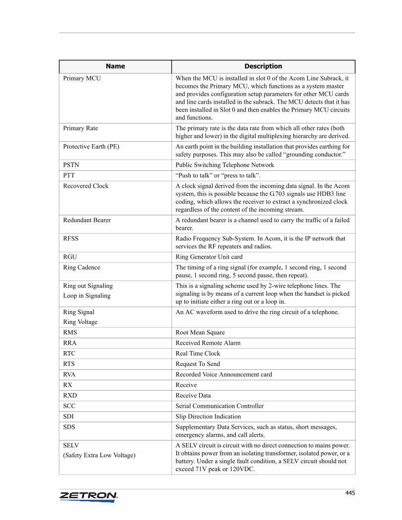
445
Primary MCU When the MCU is installed in slot 0 of the Acom Line Subrack, it becomes the Primary MCU, which functions as a system master and provides configuration setup parameters for other MCU cards and line cards installed in the subrack. The MCU detects that it has been installed in Slot 0 and then enables the Primary MCU circuits and functions.
Primary Rate The primary rate is the data rate from which all other rates (both higher and lower) in the digital multiplexing hierarchy are derived.
Protective Earth (PE) An earth point in the building installation that provides earthing for safety purposes. This may also be called “grounding conductor.”
PSTN Public Switching Telephone Network
PTT “Push to talk” or “press to talk”.
Recovered Clock A clock signal derived from the incoming data signal. In the Acom system, this is possible because the G.703 signals use HDB3 line coding, which allows the receiver to extract a synchronized clock regardless of the content of the incoming stream.
Redundant Bearer A redundant bearer is a channel used to carry the traffic of a failed bearer.
RFSS Radio Frequency Sub-System. In Acom, it is the IP network that services the RF repeaters and radios.
RGU Ring Generator Unit card
Ring Cadence The timing of a ring signal (for example, 1 second ring, 1 second pause, 1 second ring, 5 second pause, then repeat).
Ring out Signaling
Loop in Signaling
This is a signaling scheme used by 2-wire telephone lines. The signaling is by means of a current loop when the handset is picked up to initiate either a ring out or a loop in.
Ring Signal
Ring Voltage
An AC waveform used to drive the ring circuit of a telephone.
RMS Root Mean Square
RRA Received Remote Alarm
RTC Real Time Clock
RTS Request To Send
RVA Recorded Voice Announcement card
RX Receive
RXD Receive Data
SCC Serial Communication Controller
SDI Slip Direction Indication
SDS Supplementary Data Services, such as status, short messages, emergency alarms, and call alerts.
SELV
(Safety Extra Low Voltage)
A SELV circuit is circuit with no direct connection to mains power. It obtains power from an isolating transformer, isolated power, or a battery. Under a single fault condition, a SELV circuit should not exceed 71V peak or 120VDC.
Name Description
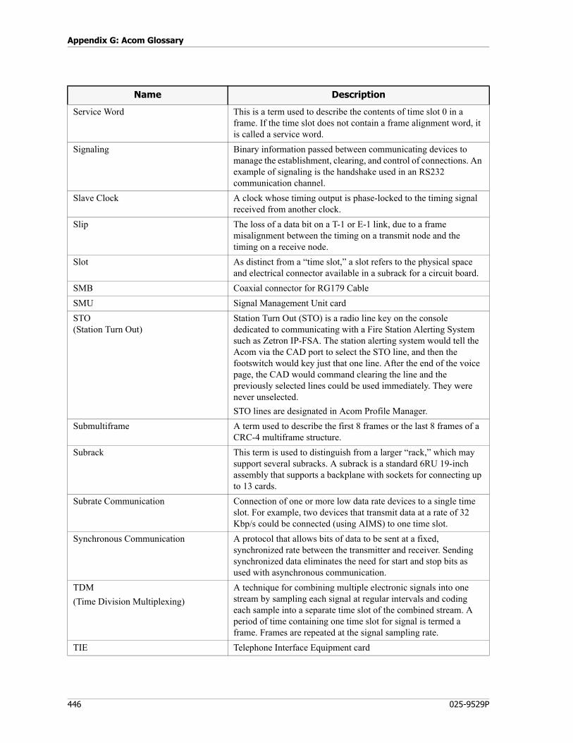
Appendix G: Acom Glossary
446 025-9529P
Service Word This is a term used to describe the contents of time slot 0 in a frame. If the time slot does not contain a frame alignment word, it is called a service word.
Signaling Binary information passed between communicating devices to manage the establishment, clearing, and control of connections. An example of signaling is the handshake used in an RS232 communication channel.
Slave Clock A clock whose timing output is phase-locked to the timing signal received from another clock.
Slip The loss of a data bit on a T-1 or E-1 link, due to a frame misalignment between the timing on a transmit node and the timing on a receive node.
Slot As distinct from a “time slot,” a slot refers to the physical space and electrical connector available in a subrack for a circuit board.
SMB Coaxial connector for RG179 Cable
SMU Signal Management Unit card
STO(Station Turn Out)
Station Turn Out (STO) is a radio line key on the console dedicated to communicating with a Fire Station Alerting System such as Zetron IP-FSA. The station alerting system would tell the Acom via the CAD port to select the STO line, and then the footswitch would key just that one line. After the end of the voice page, the CAD would command clearing the line and the previously selected lines could be used immediately. They were never unselected.
STO lines are designated in Acom Profile Manager.
Submultiframe A term used to describe the first 8 frames or the last 8 frames of a CRC-4 multiframe structure.
Subrack This term is used to distinguish from a larger “rack,” which may support several subracks. A subrack is a standard 6RU 19-inch assembly that supports a backplane with sockets for connecting up to 13 cards.
Subrate Communication Connection of one or more low data rate devices to a single time slot. For example, two devices that transmit data at a rate of 32 Kbp/s could be connected (using AIMS) to one time slot.
Synchronous Communication A protocol that allows bits of data to be sent at a fixed, synchronized rate between the transmitter and receiver. Sending synchronized data eliminates the need for start and stop bits as used with asynchronous communication.
TDM
(Time Division Multiplexing)
A technique for combining multiple electronic signals into one stream by sampling each signal at regular intervals and coding each sample into a separate time slot of the combined stream. A period of time containing one time slot for signal is termed a frame. Frames are repeated at the signal sampling rate.
TIE Telephone Interface Equipment card
Name Description
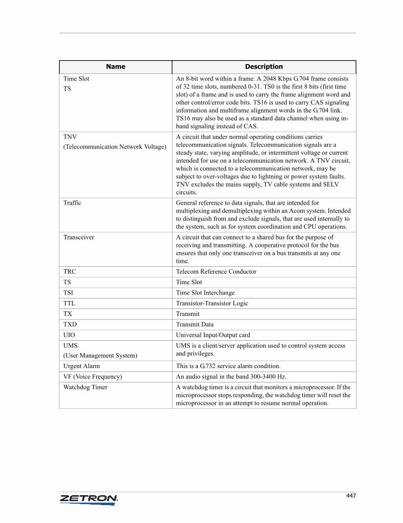
447
Time Slot
TS
An 8-bit word within a frame. A 2048 Kbps G.704 frame consists of 32 time slots, numbered 0-31. TS0 is the first 8 bits (first time slot) of a frame and is used to carry the frame alignment word and other control/error code bits. TS16 is used to carry CAS signaling information and multiframe alignment words in the G.704 link. TS16 may also be used as a standard data channel when using in-band signaling instead of CAS.
TNV
(Telecommunication Network Voltage)
A circuit that under normal operating conditions carries telecommunication signals. Telecommunication signals are a steady state, varying amplitude, or intermittent voltage or current intended for use on a telecommunication network. A TNV circuit, which is connected to a telecommunication network, may be subject to over-voltages due to lightning or power system faults. TNV excludes the mains supply, TV cable systems and SELV circuits.
Traffic General reference to data signals, that are intended for multiplexing and demultiplexing within an Acom system. Intended to distinguish from and exclude signals, that are used internally to the system, such as for system coordination and CPU operations.
Transceiver A circuit that can connect to a shared bus for the purpose of receiving and transmitting. A cooperative protocol for the bus ensures that only one transceiver on a bus transmits at any one time.
TRC Telecom Reference Conductor
TS Time Slot
TSI Time Slot Interchange
TTL Transistor-Transistor Logic
TX Transmit
TXD Transmit Data
UIO Universal Input/Output card
UMS
(User Management System)
UMS is a client/server application used to control system access and privileges.
Urgent Alarm This is a G.732 service alarm condition.
VF (Voice Frequency) An audio signal in the band 300-3400 Hz.
Watchdog Timer A watchdog timer is a circuit that monitors a microprocessor. If the microprocessor stops responding, the watchdog timer will reset the microprocessor in an attempt to resume normal operation.
Name Description

Appendix G: Acom Glossary
448 025-9529P
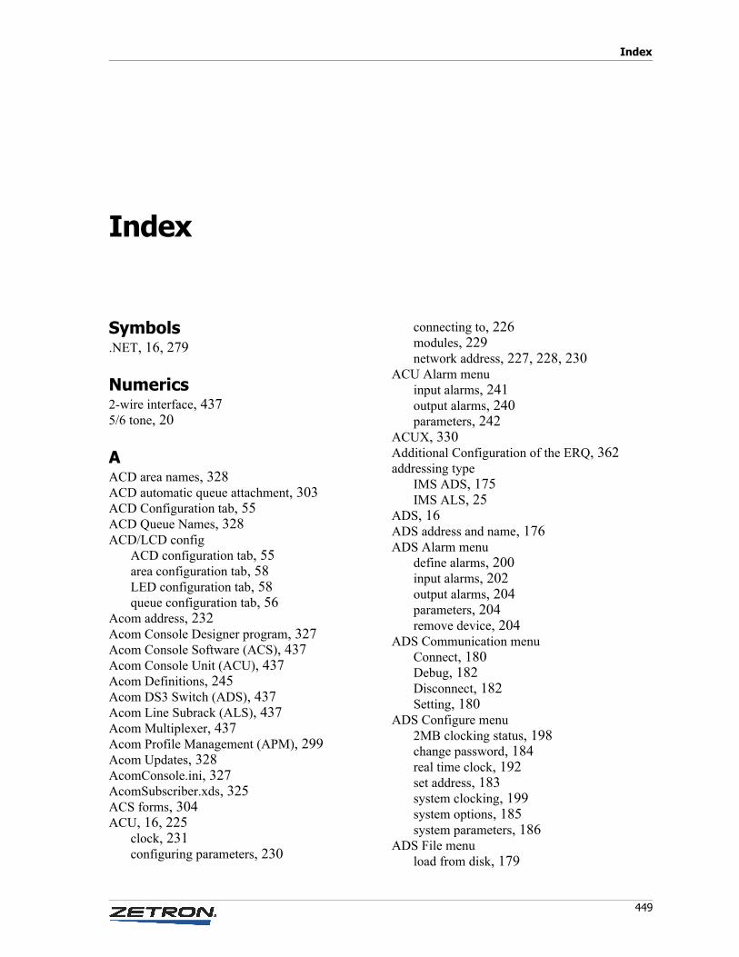
Index
449
Index
Symbols.NET, 16, 279
Numerics2-wire interface, 4375/6 tone, 20
AACD area names, 328ACD automatic queue attachment, 303ACD Configuration tab, 55ACD Queue Names, 328ACD/LCD config
ACD configuration tab, 55area configuration tab, 58LED configuration tab, 58queue configuration tab, 56
Acom address, 232Acom Console Designer program, 327Acom Console Software (ACS), 437Acom Console Unit (ACU), 437Acom Definitions, 245Acom DS3 Switch (ADS), 437Acom Line Subrack (ALS), 437Acom Multiplexer, 437Acom Profile Management (APM), 299Acom Updates, 328AcomConsole.ini, 327AcomSubscriber.xds, 325ACS forms, 304ACU, 16, 225
clock, 231configuring parameters, 230
connecting to, 226modules, 229network address, 227, 228, 230
ACU Alarm menuinput alarms, 241output alarms, 240parameters, 242
ACUX, 330Additional Configuration of the ERQ, 362addressing type
IMS ADS, 175IMS ALS, 25
ADS, 16ADS address and name, 176ADS Alarm menu
define alarms, 200input alarms, 202output alarms, 204parameters, 204remove device, 204
ADS Communication menuConnect, 180Debug, 182Disconnect, 182Setting, 180
ADS Configure menu2MB clocking status, 198change password, 184real time clock, 192set address, 183system clocking, 199system options, 185system parameters, 186
ADS File menuload from disk, 179
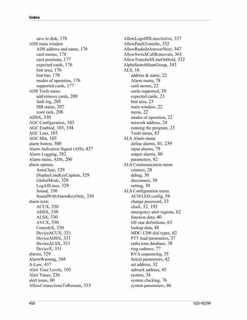
Index
450 025-9529P
save to disk, 178ADS main window
ADS address and name, 176card menus, 176card positions, 177expected cards, 176hint area, 176hint bar, 178modes of operation, 176supported cards, 177
ADS Tools menuadd/remove cards, 209fault log, 205ISB status, 207reset rack, 206
ADSX, 330AGC Configuration, 103AGC Enabled, 103, 104AGC Loss, 103AGC Min, 103alarm button, 300Alarm Indication Signal (AIS), 437Alarm Logging, 282Alarm menu, ADS, 200alarm options
AutoClear, 329DisplayLineKeyCaption, 329GlobalMode, 329LogAllLines, 329Sound, 330SoundWithAlarmKeyOnly, 330
alarm textsACUX, 330ADSX, 330ALSX, 330AVCX, 330ConsoleX, 330DeviceACUX, 331DeviceADSX, 331DeviceALSX, 331DeviceX, 331
alarms, 329AlarmWarning, 368A-Law, 437Alert Tone Levels, 103Alert Tones, 236alert tones, 60AllowConnectionsToRemain, 333
AllowLogoffIfLinesActive, 337AllowPatchTransfer, 332AllowRadioInAnswerNext, 347AllowSwitchCallRemovals, 361AllowTransferIfLineOnHold, 332AlphaSearchHuntGroup, 343ALS, 16
address & name, 22Alarm menu, 78card menus, 22cards supported, 20expected cards, 23hint area, 23main window, 22menu, 22modes of operation, 22network address, 24running the program, 23Tools menu, 83
ALS Alarm menudefine alarms, 81, 239input alarms, 79output alarms, 80parameters, 82
ALS Communication menuconnect, 28debug, 30disconnect, 30setting, 30
ALS Configuration menuACD/LED config, 54change password, 33clock, 32, 192emergency alert regions, 62function data, 40GE-star definitions, 63lookup data, 48MDC-1200 dial types, 62PTT load parameters, 37radio tone database, 38ring cadence, 77RVA sequencing, 35Selcal parameters, 42set address, 32subrack address, 45system, 34system clocking, 76system parameters, 46
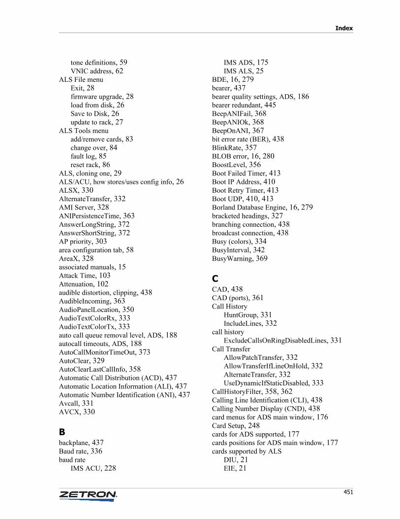
451
Index
tone definitions, 59VNIC address, 62
ALS File menuExit, 28firmware upgrade, 28load from disk, 26Save to Disk, 26update to rack, 27
ALS Tools menuadd/remove cards, 83change over, 84fault log, 85reset rack, 86
ALS, cloning one, 29ALS/ACU, how stores/uses config info, 26ALSX, 330AlternateTransfer, 332AMI Server, 328ANIPersistenceTime, 363AnswerLongString, 372AnswerShortString, 372AP priority, 303area configuration tab, 58AreaX, 328associated manuals, 15Attack Time, 103Attenuation, 102audible distortion, clipping, 438AudibleIncoming, 363AudioPanelLocation, 350AudioTextColorRx, 333AudioTextColorTx, 333auto call queue removal level, ADS, 188autocall timeouts, ADS, 188AutoCallMonitorTimeOut, 373AutoClear, 329AutoClearLastCallInfo, 358Automatic Call Distribution (ACD), 437Automatic Location Information (ALI), 437Automatic Number Identification (ANI), 437Avcall, 331AVCX, 330
Bbackplane, 437Baud rate, 336baud rate
IMS ACU, 228
IMS ADS, 175IMS ALS, 25
BDE, 16, 279bearer, 437bearer quality settings, ADS, 186bearer redundant, 445BeepANIFail, 368BeepANIOk, 368BeepOnANI, 367bit error rate (BER), 438BlinkRate, 357BLOB error, 16, 280BoostLevel, 356Boot Failed Timer, 413Boot IP Address, 410Boot Retry Timer, 413Boot UDP, 410, 413Borland Database Engine, 16, 279bracketed headings, 327branching connection, 438broadcast connection, 438Busy (colors), 334BusyInterval, 342BusyWarning, 369
CCAD, 438CAD (ports), 361Call History
HuntGroup, 331IncludeLines, 332
call historyExcludeCallsOnRingDisabledLines, 331
Call TransferAllowPatchTransfer, 332AllowTransferIfLineOnHold, 332AlternateTransfer, 332UseDynamicIfStaticDisabled, 333
CallHistoryFilter, 358, 362Calling Line Identification (CLI), 438Calling Number Display (CND), 438card menus for ADS main window, 176Card Setup, 248cards for ADS supported, 177cards positions for ADS main window, 177cards supported by ALS
DIU, 21EIE, 21
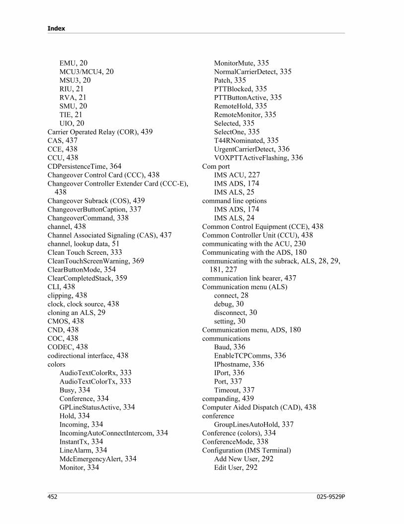
Index
452 025-9529P
EMU, 20MCU3/MCU4, 20MSU3, 20RIU, 21RVA, 21SMU, 20TIE, 21UIO, 20
Carrier Operated Relay (COR), 439CAS, 437CCE, 438CCU, 438CDPersistenceTime, 364Changeover Control Card (CCC), 438Changeover Controller Extender Card (CCC-E),
438Changeover Subrack (COS), 439ChangeoverButtonCaption, 337ChangeoverCommand, 338channel, 438Channel Associated Signaling (CAS), 437channel, lookup data, 51Clean Touch Screen, 333CleanTouchScreenWarning, 369ClearButtonMode, 354ClearCompletedStack, 359CLI, 438clipping, 438clock, clock source, 438cloning an ALS, 29CMOS, 438CND, 438COC, 438CODEC, 438codirectional interface, 438colors
AudioTextColorRx, 333AudioTextColorTx, 333Busy, 334Conference, 334GPLineStatusActive, 334Hold, 334Incoming, 334IncomingAutoConnectIntercom, 334InstantTx, 334LineAlarm, 334MdcEmergencyAlert, 334Monitor, 334
MonitorMute, 335NormalCarrierDetect, 335Patch, 335PTTBlocked, 335PTTButtonActive, 335RemoteHold, 335RemoteMonitor, 335Selected, 335SelectOne, 335T44RNominated, 335UrgentCarrierDetect, 336VOXPTTActiveFlashing, 336
Com portIMS ACU, 227IMS ADS, 174IMS ALS, 25
command line optionsIMS ADS, 174IMS ALS, 24
Common Control Equipment (CCE), 438Common Controller Unit (CCU), 438communicating with the ACU, 230Communicating with the ADS, 180communicating with the subrack, ALS, 28, 29,
181, 227communication link bearer, 437Communication menu (ALS)
connect, 28debug, 30disconnect, 30setting, 30
Communication menu, ADS, 180communications
Baud, 336EnableTCPComms, 336IPhostname, 336IPort, 336Port, 337Timeout, 337
companding, 439Computer Aided Dispatch (CAD), 438conference
GroupLinesAutoHold, 337Conference (colors), 334ConferenceMode, 338Configuration (IMS Terminal)
Add New User, 292Edit User, 292
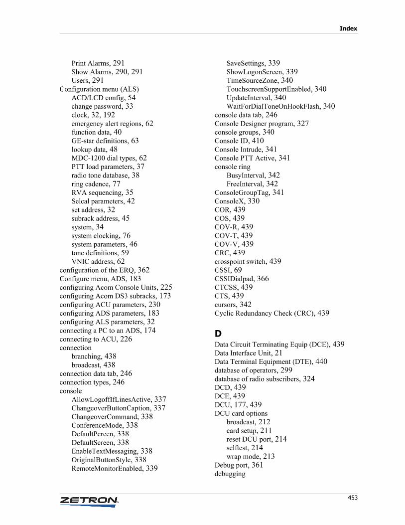
453
Index
Print Alarms, 291Show Alarms, 290, 291Users, 291
Configuration menu (ALS)ACD/LCD config, 54change password, 33clock, 32, 192emergency alert regions, 62function data, 40GE-star definitions, 63lookup data, 48MDC-1200 dial types, 62PTT load parameters, 37radio tone database, 38ring cadence, 77RVA sequencing, 35Selcal parameters, 42set address, 32subrack address, 45system, 34system clocking, 76system parameters, 46tone definitions, 59VNIC address, 62
configuration of the ERQ, 362Configure menu, ADS, 183configuring Acom Console Units, 225configuring Acom DS3 subracks, 173configuring ACU parameters, 230configuring ADS parameters, 183configuring ALS parameters, 32connecting a PC to an ADS, 174connecting to ACU, 226connection
branching, 438broadcast, 438
connection data tab, 246connection types, 246console
AllowLogoffIfLinesActive, 337ChangeoverButtonCaption, 337ChangeoverCommand, 338ConferenceMode, 338DefaultPcreen, 338DefaultScreen, 338EnableTextMessaging, 338OriginalButtonStyle, 338RemoteMonitorEnabled, 339
SaveSettings, 339ShowLogonScreen, 339TimeSourceZone, 340TouchscreenSupportEnabled, 340UpdateInterval, 340WaitForDialToneOnHookFlash, 340
console data tab, 246Console Designer program, 327console groups, 340Console ID, 410Console Intrude, 341Console PTT Active, 341console ring
BusyInterval, 342FreeInterval, 342
ConsoleGroupTag, 341ConsoleX, 330COR, 439COS, 439COV-R, 439COV-T, 439COV-V, 439CRC, 439crosspoint switch, 439CSSI, 69CSSIDialpad, 366CTCSS, 439CTS, 439cursors, 342Cyclic Redundancy Check (CRC), 439
DData Circuit Terminating Equip (DCE), 439Data Interface Unit, 21Data Terminal Equipment (DTE), 440database of operators, 299database of radio subscribers, 324DCD, 439DCE, 439DCU, 177, 439DCU card options
broadcast, 212card setup, 211reset DCU port, 214selftest, 214wrap mode, 213
Debug port, 361debugging
Index
454 025-9529P
remote, 30, 182, 361decadic signaling, 439Decay Time, 103Decoder Gain, 104De-emphasis Filter, 104De-emphasize, 104default password, 29, 181, 227DefaultMuteLevel, 359DefaultPcreen, 338DefaultScreen, 338Delay Time, 103detect string, lookup data, 49detect type, lookup data, 48DeviceACUX, 331DeviceADSX, 331DeviceALSX, 331DeviceX, 331dfm file, 327DFSI, 65, 72DFSIDialpad, 366dial pad
AlphaSearchHuntGroup, 343DialPlanLength, 343ExternalDialingPrefix, 343RetainPreviousSelect, 343Timeout, 344
DialPlanLength, 343dialup radio, lookup data, 52DID, 439differential data, 439digital crosspoint switch, 439Digital I/O, 234digital I/O for ACU, 229digital inputs, 234digital multiplex hierarchy, 440Digital Outputs, 344digital outputs, 234DigitalIOWarning, 369disable multiple holds, ADS, 188DisableMuteModes, 341disableTX line group, 303Dispatcher Login UDP, 414DisplayLineKeyCaption, 329DisplayMatchingSelcalOnly, 362DisplayMonitorFunctionColor, 364DisplayNumberOfEndPoint, 372DisplayOutgoingPTT, 364DIU, 21, 440
DIU card optionsAcom definitions, 147card setup, 147loopback, 149selftest, 150signaling monitor, 147
downloadX, 328DPLL, 440DS3, 440DS3 subracks, 16, 173DSR, 440DTE, 440DTMF, 20, 440DTMF Off Time, 103DTMF On Time, 103DTR, 440Dual 4W E&M Module
Acom Definitions, 250Gain Setting, 252Loopback, 254Signaling Inversion, 253Signaling Monitor, 250
Dual E1 Module2Mb Link Monitor, 2622Mb Link Settings, 2602Mb Link Tests, 261Acom Definitions, 255Loopback, 259Selftest, 263Signaling Inversion, 259Signaling Monitor, 254
Dual Tones, 103
EE&M signaling, 440E1 links, 21each MCU is independent 2-port device, ADS,
185Ear and Mouth unit, 20earth recall signal, 440EBER, 440EIE, 21, 440EIE card options
Acom definitions, 161gain setting, 164learn line parameters, 165loopback, 166selftest, 161
455
Index
signaling monitor, 160special setting, 165
EIU Card Options, 215card settings, 218port mode, 216selftest, 216
EMC, 440emergency alert regions, 410Emergency Alert UDP, 414EmergencyAlertAudiblePeriod, 373EmergencyAlertWarning, 369EmergencyCallStatus, 367EMI, 440EMU, 20, 440EMU card options
Acom definitions, 129gain setting, 136LEDs, 137loopback, 137self test, 129signaling inversion, 136
enable conference beeps, ADS, 188EnableIRR, 353EnableIRRSoftwareControl, 353EnablePCTonesToAudioPanel, 352, 353EnablePCTonesToHandset, 352, 353EnablePCTonesToMonSpk1, 351EnablePCTonesToMonSpk2, 351, 352EnablePCTonesToMonSpk3, 351, 352EnablePCTonesToMonSpk4, 351, 352EnableTCPComms (communications), 336EnableTextMessaging, 338EnableUMS, 374Encryption, 73end of page selected lines, 320EPIC, 440ERQ, configuration of, 362ESD, 440ETSI, 440events to make port offline, ADS, 186Excessive Bit Error Rate, 440Exchange Interface Equipment, 21Exchange Interface Equipment (EIE), 440ExcludeCallsOnRingDisabledLines, 331, 347Exit, ALS, 28expected cards, 23expected cards for ADS main window, 176Extended card parameters
common, 142normal mode, 142OpenSky modes, 144P25 mode, 143
ExternalDialingPrefix, 343
FFailsoft, 67FAS, 441Fast Keys, 345fault display, ADS, 206fault log, 244Fault Log, ADS
fault display, 206Filename, 360firmware upgrade, ALS, 28Flash RAM, 178Floating IP Address, 218, 413form file, 327forms assigned for ACS, 304FPGA, 441frame alignment, 441Frame Alignment Signal (FAS), 441frame, frame data, 441framer, 441FreeInterval, 342
Ggain, 441Gateway IP Address, 218, 413Gateway UDP, 414GCT, 68GE-Star, 347GlobalMode, 329GPLineStatusActive, 334GroupLinesAutoHold, 337
HHandsetLocation, 350HandsetOnly, 350handshaking, 441HDB3, 441HDLC, 441High Density Bipolar of Order 3 (HDB3), 441High-Level Data Link Control (HDLC), 441hint area, 23hint area for ADS main window, 176

Index
456 025-9529P
hint bar for ADS main window, 178Hold (colors), 334HoldFunctionality, 354HoldPriority, 355HoldWarning, 369, 373hot plugging, 441how ADS store/uses config info, 178how ALS/ACU stores/uses config info, 26HS priority, 303Hunt Group, 233HuntGroup, 331
IIDF, 441IGMP, 67IMS, 442IMS ACU, 16, 225
data ports, 229Dual 4W E&M Module, 250Dual E1 Module, 254launching, 226menus, 228modes of operation, 226Operator’s Audio Module, 263startup options, 227using with/without IMS Terminal, 226
IMS ACU configure menuAcom address, 232Alert Tones, 236change password, 231clock, 231Digital I/O, 234Hunt Group, 233set network address, 230System Clocking, 237
IMS ACU Data Ports ModuleAcom Definitions, 245Card Setup, 248Loopback, 249Signaling Monitor, 245
IMS ACU Tools menufault log, 244link change over, 243reset rack, 244
IMS ADS, 16, 173command line options, 174connecting a PC, 174main window, 176
managing configurations, 178reload config, 179startup options, 174update to rack, 179with/without IMS Terminal, 173
IMS ALS, 16, 19, 21command line options, 24startup options, 24
IMS module, 327IMS Terminal, 16, 21, 279
Alarms, 293Configuration, 290, 291installing, 279Locking the Console, 285Logging on and Off, 285Option Setup Program, 280starting, 282System Map Setup, 285Tools, 289
IMS terminal, 441IMS Terminal Main Window
Main Menu, 284Map Display Area, 284Map Selection Area, 284Status Bar, 284
IMS_Terminal.ini, 282, 283IMSTerminal.log, 282inband signaling, 442IncludeLines, 332Incoming (colors), 334Incoming Call Queue, 348Incoming Calls, 348IncomingAutoConnectIntercom (colors), 334IncomingCallPopups, 348initial level
MonitorSpeakerVolume, 348SelectSpeakerLevel, 348
InitialLevel (line volume), 356InitialMonitorLevel, 356installation order, 16installing IMS Terminal, 279Instant Recall Recorder, 442InstantTx (colors), 334Integrated Management System (IMS), 442Integrated Services Digital Network, 442interactive voice response (IVR), 35IntercomAutoconnect, 369intercoms
457
Index
ShowAnnounce, 349ShowBroadcast, 349SingleAutoConnectOnly, 349
interfacesAudioPanelLocation, 350HandsetLocation, 350HandsetOnly, 350PhonePriority, 350
Internet Signaling UDP, 413intersite bearer, 177inter-site bearer groups, 208IOM-2, 442IP Address, 413IP Subnet Mask, 413IPAT, 442IPhostname (communications), 336IPort (communications), 336IRR, 442
EnableIRR, 353EnableIRRSoftwareControl, 353IRRChannelAlias, 353
IRRChannelAlias, 353ISB redundancy, 186, 221, 222ISDN, 442ISDN Oriented Modular Bus, v2, 442ISDN Primary Access Transceiver, 442IVR, 35
KKeepPTTID, 364key loader, 74Keydown Delay, 104KeyFn, 345Keyup Delay, 104
LLAN Link Fail-Interval Until Alarm, 219, 413launching IMS ACU, 226LCB, 442LeadInDelay, 331LED configuration tab, 58Level, 103line break, 442line card, 442line group associations, 299Line Groups, 354line select
ReserveGroupSelect, 355line selection
ClearButtonMode, 354HoldFunctionality, 354HoldPriority, 355PreventLineIntrude, 355PreventPhoneMonitor, 355PreventRadioLineTransfer, 355ResetVolumeOnSelect, 355
line volumeBoostLevel, 356InitialLevel, 356InitialMonitorLevel, 356
LineAlarm (colors), 334LineGroupName, 375LinesOnHold, 341link, 442link change over, 243LMFA, 442Local Digital Inputs, 356Local Digital Outputs, 357LocalGPDigitalInputX, 356LocalGPDigitalOutputDigOut#, 344Locking the Console, 285LogAllLines, 329logging on and off IMS Terminal, 285logon information, 302LogonScreenDefaultLanguage, 338LogPagingActivity, 360lookup data channel, 51lookup data detect string, 49lookup data detect type, 48lookup data dialup radio, 52lookup data response string, 51lookup data response type, 50loop detect, 443loop out, 443loop seize, 443loop signaling, 445Loopback, 249LOS, 443loss of sync, 443
MM25ES, 319MAC addresses, 209Main Control Unit, 443main control unit, 20
Index
458 025-9529P
Main Control Unit (MCU), 417main supply unit, 20main window for ADS, 176main window IMS ACU
communication menu, 230configure menu, 230data ports, 229digital I/O, 229file menu, 229menus, 228modules, 229network address, 228
main window, IMS ALS, 22managing configurations, 25managing configurations in IMS ACU, 229managing network devices with IMS Terminal,
279manual, getting the best use, 16manuals, 15marker tone, 60master clock, 443master source, ADS, 187Max Boot Retries, 413MCU, 417, 443MCU in slots 2&3 combined as one 4-port
device, ADS, 185MCU3, 20MCU3/4 card options
2Mb link monitor, 1212Mb link settings, 1192Mb link tests, 120Acom definitions, 89alarm definitions, 122link signaling, 112loopback, 118serial port, 115signaling inversion, 117signaling monitor, 89
MCU4, 20, 177MCU4 card options
2Mb link settings, 224link monitor, 224port mode, 216, 219selftest, 216, 219
MDCAutoClearLastCallInfo, 358CallHistoryFilter, 358, 362MomentarySelectiveCall, 358
StatusTextX, 358MdcEmergency, 369MdcEmergencyAlert (colors), 334MDF, 443mian window IMS ACU
status/hint bar, 229Microsoft .NET Framework, 16, 279Mobile Quert UDP, 414modes of operation for ALS, 22modes of operation for IMS ACU, 226modes of operation, ADS, 176modules for ACU, 229MomentarySelectiveCall, 358Monitor, 359Monitor (colors), 334MonitorMute (colors), 335MonitorSpeakerVolume, 348Mouse, 359MSU, 443MSU3, 20, 177MSU3 card options
Acom definitions, 124alarm setup, 128gain setting, 126selftest, 123signaling inversion, 127signaling monitor, 123
multiframe, 443MUSAC, 443MuteAll, 373MuteRadios, 374MUX, 443
NName, line groups, 354NAS, 411network address
IMS ADS, 174IMS ALS, 25
network address for ACU, 227network address for ALS, 24Network Administration System (NAS), 411non urgent alarm, 443NormalCarrierDetect (colors), 335NOS, 443NotReadySound, 369NRZ, 443Number of Time Slots, 416
459
Index
OOAM, 444on hold transfer, 332OpenSky, 142, 419OpenSky configuration, 409OpenSky registration information, 303OpenSkyID, 299OperationMode, 348Operator’s Audio Module
Acom Definitions, 264AGC Settings, 275Audio Option tab, 269Connection Data tab, 266, 272Console Interface tab, 267, 274Console PC Tones, 271Console Speakers, 270Gain Setting, 274Loopback, 277Nromal Connection, 265
Optical Switch, 84, 185Option Setup
Addressing Mode, 281Alarms to Printer, 281Alarms to Screen, 282Applications, 282Baud Rate, 281Communication Port, 281Connection Mode, 281Get Mode at Startup, 281Modem Init String, 281Number to Dial, 281
Option Setup Program, 280order wire, 444OriginalButtonStyle, 338OriginateLongString, 372OriginateShortString, 372
PP25, 65, 142P25, talker IDs, 371PABXdelay, 372page stack configuration, 320PageComplete, 369PagerTxMask, 367paging
ClearCompletedStack, 359Filename, 360
LogPagingActivity, 360PlayTones, 360SafetyMode, 360VoiceHoldTime, 361
Paging Configuration, 60Paging Loopback Gain, 104, 360paging tones, 60, 62, 103partial time slot allocation, 444password, 302
IMS ACU, 227IMS ADS, 174IMS ALS, 25retrieving lost, 33, 184, 231
Patch (colors), 335patch transfer, 332PCM, 444PCM-30, 444PE, 444Phase Locked Loop, 444PhonePriority, 350Ping Gap Period, 218, 413PlayTones, 360PLL, 444Pool ID, 410Port (communications), 337port combining mode, ADS, 185ports
CAD, 361Debug, 361Web, 361
Power Limiter Settings, 102Pre-emphasis Filter, 104Pre-emphasize, 104PreventLineIntrude, 355PreventPhoneMonitor, 355PreventRadioLineTransfer, 355primary MCU, 445primary rate, 445priority, HS or AP, 303Private TalkPaths, 410Profiles.xml, 300Protective Earth (PE), 445Provisioning UDP, 413pseudo duplex group, ADS, 53, 188PSTN, 445PTT, 445PTT Priorities, 299PTTBlocked (colors), 335
Index
460 025-9529P
PTTBlockedWarning, 370PTTButtonActive (colors), 335PTTID, 347PTTOverrideWarning, 370Pulse Code Modulation, 444
QQoS, 68queue box
AllowSwitchCallRemovals, 361DisplayMatchingSelcalOnly, 362
queue configuration tab, 56QueueX, 328
RRadio Interface Unit, 21radio lines
ANIPersistenceTime, 363AudibleIncoming, 363CDPersistanceTime, 364DisplayMonitorFunctionColor, 364DisplayOutgoingPTT, 364KeepPTTID, 364ReplaceKeyCaptionWithEndPointInfo, 364ShowActivityIfNotSelected, 364ShowCDAsKeyColorChangeIfIdle, 365ShowCDIfSelectedAs, 365
RadioIncoming, 370RAM, 178RecallDialtone, 374Receive Audio Delay, 103Recorded Voice Announcement, 21Recovered Clock, 445redundant bearer, 445register OpenSky VNICs, 409registration information, OpenSky, 303reload config, ADS, 179remote debugging, 30, 182, 361RemoteHold (colors), 335RemoteMonitor (colors), 335RemoteMonitorEnabled, 339ReplaceKeyCaptionWithEndPointInfo, 364,
373ReserveGroupSelect, 355reset rack, 244ResetVolumeOnSelect, 355response string, lookup data, 51
response type, lookup data, 50RetainPreviousSelect, 343RFSS, 66, 69, 445RGU, 445ring cadence, 445ring out signaling, 445ring signal, 445ring voltage, 445RingBusy, 370RingerMutePeriod, 374RingIntercomIdle, 370RingPhoneIdle, 370RingPhoneUrgent, 370RingRadioIdle, 371RingRadioUrgent, 371RIU, 21RIU card options
Acom definitions, 151card settings, 152loopback, 156signaling inversion, 156signaling monitor, 151
RMS, 445role number, 303role, UMS.screens, 374Router IP Address, 218, 413Router Ping
Interval, 218, 413Retries Until Failure, 218, 413Retry Interval, 218, 413
RRA, 445RTC, 445RTP, 68RTS, 445running the program, 23RVA, 21, 445RVA card options
Acom definitions, 157record sounds, 158
RX, 445RXD, 445RxMask, 368
SSafety Extra Low Voltage (SELV), 445SafetyMode, 360SaveSettings, 339SCC, 445
461
Index
Screen Positions, 365screens
CSSIDialpad, 366DFSIDialpad, 366SelcallDialpad, 366TelephoneQuickDial, 367
SDI, 445SDS, 445Selcal, 20
BeepOnANI, 367EmergencyCallStatus, 367PagerTxMask, 367RxMask, 368ShowAckANI, 368ShowLinename, 368
Selcal Level, 104SelcalEmergencyIncoming, 371SelcallDialpad, 366SelcalRoleIncoming, 371Selected (colors), 335selected lines
end of page, 320Selective Call UDP, 414SelectOne (colors), 335SelectSpeakerLevel, 348SELV, 445send alarms to bearers, ADS, 188SepacIncomingNormal, 371SepacIncomingUrgent, 371Sequential, 104Sequential Rx, 104Sequential Tx, 104service word, 446ShowAckANI, 368ShowActivityIfNotSelected, 364ShowAnnounce, 349ShowBroadcast, 349ShowCDAsKeyColorChangeIfIdle, 365ShowCDIfSelectedAs, 365ShowDialpadForCB, 373ShowLinename, 368ShowLogonScreen, 339signal management unit, 20signaling, 446Signaling Management Unit (SMU), 411Signaling Monitor, 245SingleAutoConnectOnly, 349SIP, 67
site address, ADS, 187slave clock, 446slip, 446slot, 446SMB, 446SMU, 20, 411, 446SMU card options
Acom definitions, 138gain setting, 144
SMU resources, 414software installation order, 16Sound, 330sounds
AlarmWarning, 368BeepANIFail, 368BeepANIOk, 368BusyWarning, 369CleanTouchScreenWarning, 369DigitalIOWarning, 369EmergencyAlertWarning, 369HoldWarning, 369IntercomAutoconnect, 369MdcEmergency, 369NotReady, 369PageComplete, 369PTTBlockedWarning, 370PTTOverrideWarning, 370RadioIncoming, 370RingBusy, 370RingIntercomIdle, 370RingPhoneIdle, 370RingPhoneUrgent, 370RingRadioIdle, 371RingRadioUrgent, 371SelcalEmergencyIncoming, 371SelcalRoleIncoming, 371SepacIncomingNormal, 371SepacIncomingUrgent, 371TxClearVoiceWarning, 371
SoundWithAlarmKeyOnly, 330Source Circuit, 416Source Slot Number, 416stabilization/destabilization, ADS, 186standby bearer, 186, 222Starting IMS Terminal, 282startup options
IMS ADS, 174IMS ALS, 24
Index
462 025-9529P
startup options for IMS ACU, 227status/hintbar for IMS ACU, 229StatusTextX, 358sub-multiframe, 446subrack, 446subrack backplane, 437subrate communication, 446subscriber configuration program, 324SUID, 71supervisor, 300Supervisor setting, 304Supplimentary Data Services, 445synchronous communication, 446System Clocking, 237System Map Setup
retrieve from router, 289send to router, 288using the map builder, 286
system options, ADSbearer quality settings, 186each MCU is independent 2-port device, 185events to make port offline, 186MCU in slots 2&3 combined as one 4-port
device, 185port combining mode, 185stabilization/destabilization mode, 186
system parameters, ADSauto call queue removal level, 188autocall timeouts, 188disable multiple holds, 188enable conference beeps, 188master source, 187pseudo duplex group, 53, 188send alarms to bearers, 188site address, 187
system tones, 59
TT1 links, 21T44RNominated (colors), 335talker IDs
P25, 371TalkerIDrequired, 372
TalkerIDrequired, 372TalkGroup Management UDP, 413TalkGroups, 70, 419TalkPath # Control UDP, 414TalkPath # Voice UDP, 414
TalkPaths, 410TDM, 446Telecommunication Network Voltage (TNV),
447Telephone Interface Equipment, 21telephone lines
AnswerLongString, 372AnswerShortString, 372DisplayNumberOfEndPoint, 372OriginateLongString, 372OriginateShortString, 372PABXdelay, 372ReplaceKeyCaptionWithEndPointInfo, 373ShowDialpadForCB, 373
TelephoneQuickDial, 367terminal, IMS, 441Threshold, 102, 103TIE, 21, 446TIE card options
Acom definitions, 168gain setting, 170loopback, 171selftest, 168signaling monitor, 167special setting, 171
Time Division Multiplexing (TDM), 446Time Slot (TS), 447Time Slots, number of, 416Timeout (communications), 337Timeout (dial pad), 344timeout periods
AutoCallMonitorTimeOut, 373EmergencyAlertAudiblePeriod, 373HoldWarning, 373MuteAll, 373MuteRadios, 374RecallDialtone, 374RingerMutePeriod, 374
TimeSourceZone, 340TNV, 447Tone Definitions, 103tone definitions
alert tones, 60marker tone, 60system tones, 59
Tone Level, 104Tools (IMS Terminal)
Find Device, 289
463
Index
Find Map, 290Receive File, 290Refresh All Files, 290Send File, 290
Tools menu, 243Tools menu (ALS)
add/remove cards, 83change over, 84fault log, 85reset rack, 86
Tools menu, ADS, 205TouchscreenSupportEnabled, 340TrackMovement, 359traffic, 447transceiver, 447Transport slot, 416TRC, 447TS, 447TSI, 447TTL, 447TX, 447TX line group, disable, 303TxClearVoiceWarning, 371TXD, 447
UUDP
boot, 413dispatcher login, 414emergency alert, 414Gateway, 414internet signaling, 413mobile query, 414provisioning, 413selective call, 414TalkGroup management, 413TalkPath # Control, 414TalkPath # Voice, 414
UIO, 20, 447UIO card options, 144UMD, 374UMS, 447
UMS.screens, 374universal input/output, 20update to rack, ADS, 179update to rack, ALS, 27UpdateInterval, 340urgent alarm, 447UrgentCarrierDetect (colors), 336UseDynamicIfStaticDisabled, 333User Defined Line Groups, 375user details, 302User Management System (UMS), 299, 447using IMS ACU with/without IMS Terminal,
226using IMS ALS without IMS Terminal, 21using this manual, 16Utility Audio, 247utility audio, 92
VVF, 447VNIC, 409VNIC Region, 410, 419Voice Frequency (VF), 447VoiceHoldTime, 361Voide Network Interface Controller (VNIC), 409VOX Gating, 103Vox Hold Time, 102Vox Level, 102, 103Vox Settings, 102, 252, 269, 275VOXPTTActiveFlashing (colors), 336
WWaitForDialToneOnHookFlash, 340Watchdog Timer, 447Web (ports), 361Window Type, 365working with 2-tone pages, 317
ZZetron Account Management (ZAM), 299

Index
464 025-9529P


![L19 [Acon] Esquema eléctrico](https://img.dokumen.tips/doc/110x75/62c49c06196c397f48663d8e/l19-acon-esquema-elctrico.jpg)