Embed Size (px)
Citation preview
Powers 1
ACNS/Telecommunications Design Standards
Revision 22.3 – Aug. 6, 2020
601 S. Howes Street 601 S. Howes Street
Fort Collins, Colorado 80523-1018 Fort Collins, Colorado 80523-1009
www.acns.colostate.edu www.telecom.colostate.edu

Powers 2
Table of Contents
1 Introduction ...................................................................................................................5
1.1 General intent ........................................................................................................ 5
1.2 Teams Involved in Design Process ...................................................................... 5
1.3 Applicable Standards ............................................................................................ 6
1.4 General Guidelines ............................................................................................... 7
1.5 Equipment and Materials Specifications .............................................................. 7
1.6 Contractor Certifications ....................................................................................... 8
1.7 Exceptions ............................................................................................................. 8
2 Horizontal Infrastructure...............................................................................................9
2.1 General Provisions ................................................................................................ 9
2.2 Cable Colors.......................................................................................................... 9
2.3 Plenum Spaces ..................................................................................................... 9
2.4 Underground Cable ............................................................................................. 10
2.5 Patch Cords......................................................................................................... 10
2.6 Asbestos .............................................................................................................. 10
2.7 Conduit ................................................................................................................ 11
2.8 Installation of Cable Trays .................................................................................. 12
2.9 Testing and Reporting of Test Results ............................................................... 12
2.10 Systimax Certification ...................................................................................... 13
2.11 As-Builds .......................................................................................................... 13
2.12 Drop (Circuit) Labeling..................................................................................... 13
2.13 Labels ............................................................................................................... 13
2.14 Invasive Work .................................................................................................. 13
2.15 Scheduling for the Pulling of Cable ................................................................. 13
3 Communication Rooms..............................................................................................15
3.1 General Provisions .............................................................................................. 15
3.2 Main Distribution Frame (MDF) .......................................................................... 16
3.3 Intermediate Distribution Frame (IDF) ................................................................ 19
3.4 Offices ................................................................................................................. 21
3.5 Grounding and Bonding ...................................................................................... 22
4 Riser/Building Backbone Infrastructure .....................................................................23
5 Building Entrance Infrastructure ................................................................................25
5.1 General Provisions .............................................................................................. 25

Powers 3
5.2 University Policy Governing Entrance Infrastructure ......................................... 25
6 Outside Plant Infrastructure .......................................................................................26
6.1 Introduction and Project Conditions ................................................................... 26
6.2 Landscaping, Irrigation Systems, Site Protection and Excavation .................... 27
6.3 Directional Boring Specifications ........................................................................ 27
6.4 Trenching ............................................................................................................ 28
6.5 Steam Tunnel Cable Installation......................................................................... 28
7 Network Switches .......................................................................................................29
7.1 General Provisions .............................................................................................. 29
7.2 General Switch Standards: ................................................................................. 29
7.3 MDF Switches Additional Standards: ................................................................. 30
8 Wireless Access Points and Devices ........................................................................31
8.1 General Provisions .............................................................................................. 31
8.2 Wall Mounted Wireless: ...................................................................................... 32
8.3 Suspended Ceiling Mounted Wireless: .............................................................. 32
8.4 Open Ceiling Wireless: ....................................................................................... 32
8.5 Outdoor Mounted Wireless: ................................................................................ 33
8.6 Hard Lid Ceiling Mounted Wireless: ................................................................... 33
9 VOIP ...........................................................................................................................33
10 TV/Video .....................................................................................................................33
11 Emergency and Inter/Intra Building Life and Safety Infrastructure ...........................34
12 Classroom Standards ................................................................................................34
12.1 Introduction ...................................................................................................... 34
12.2 Description of General Assignment Classrooms ............................................ 35
12.3 Large Classroom, 100+ Seats......................................................................... 36
12.4 Medium Classroom: 50-100 Seats .................................................................. 38
12.5 Small Classroom: Fewer than 50 Seats ......................................................... 39
12.6 Conference Rooms .......................................................................................... 39
12.7 All Rooms with Lecture Capture Function, Any Size: ..................................... 40
12.8 Standard Lectern Design ................................................................................. 40
12.9 Lectern Power and Data Requirements .......................................................... 41
12.10 Equipment Specifications ................................................................................ 42
12.11 Video, Data Projector and Lighting Specifications ......................................... 43
12.12 Control System Specifications ........................................................................ 43
12.13 Control Design Specifications ......................................................................... 44

Powers 4
12.14 Audio System Specifications ........................................................................... 45
12.15 Network Design ............................................................................................... 45
12.16 Build Specifications ......................................................................................... 46
12.17 Networks .......................................................................................................... 50
12.18 Final System Checks and Testing .................................................................. 50
13 Miscellaneous.............................................................................................................52
13.1 Security and Access to Communication Rooms............................................. 52
13.2 Communication Room Numbering .................................................................. 52
13.3 Building automation provisioning and permanent network solution: .............. 53
Appendices ........................................................................................................................54
Appendix A – Network Switch Protocol Specifications ................................................ 54
Appendix B – Communication Room Layout ............................................................... 55
Appendix C – Wall Mounted Wireless .......................................................................... 56
Appendix D – Suspended Ceiling Mounted Wireless .................................................. 57
Appendix E – Open Ceiling Mounted Wireless ............................................................ 58
Appendix F – Outdoor Mounted Wireless .................................................................... 59
Appendix G – Hard Lid Ceiling Mounted Wireless ...................................................... 60
Appendix H – Main Building Ground ............................................................................ 61
Appendix I - Typical grounding and bounding scheme for a multistory building. ....... 62
Appendix J: Touch screen design samples ................................................................. 63

Powers 5
1 Introduction
1.1 General intent
This document provides design specifications for voice, video and data
communications infrastructure at Colorado State University (CSU), otherwise
referred to as the University. The offices of Academic Computing and Networking
Services (ACNS) along with the office of Telecommunications oversee
data/voice/video infrastructure design, construction, installation, operation,
maintenance, upgrades and monitoring for CSU sites.
While various construction challenges may dictate modifications to these
specifications, any modifications require written approval by ACNS/Telecom.
Changes to these specifications, with or without written approval, may incur time
and materials charges for any subsequent support of the facility and its installed
data/voice/video infrastructure.
1.2 Teams Involved in Design Process
Several teams are responsible for the communications infrastructure and should
be involved in the design process. These include 1) Telecommunications for the
physical infrastructure, 2) Academic Computing and Networking Services
(ACNS) for the network equipment and video and 3) Classroom Support Services
for classrooms. Contacts for these teams are given below.
Table 1. Contacts
Team Name Role Phone
ACNS/
Telecommunications
Jason Huitt Interim
Assoc. Dir.
(970) 491-2511
Telecommunications
Projects
William
Tremelling
Team Lead (970) 491-3839
Classroom Support
Services
Jamie McCue
Allen Sneesby
Interim Team
Lead
Classroom
support
(970) 491-4147
(970) 491-6038
The Telecommunications Projects Team Lead is to be involved in all phases of
design and construction along with any time questions arise during the project.

Powers 6
1.3 Applicable Standards
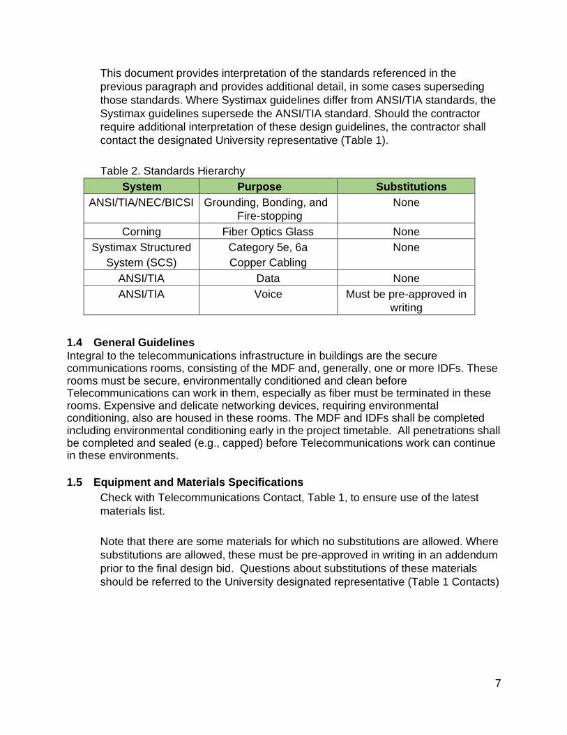
This document provides interpretation of the standards referenced in the
previous paragraph and provides additional detail, in some cases superseding
those standards. Where Systimax guidelines differ from ANSI/TIA standards, the
Systimax guidelines supersede the ANSI/TIA standard. Should the contractor
require additional interpretation of these design guidelines, the contractor shall
contact the designated University representative (Table 1)
Telecommunications physical infrastructure as defined by the American National
Standards Institute/Telecommunications Industry Association, or ANSI/TIA,
consists of seven elements: 1. Horizontal Infrastructure; 2. building main
telecommunications room or Main Distribution Frame (MDF); 3. backbone
cabling; 4. Intermediate Distribution Frames (IDFs); 5. Entrance facility (EF); 6.
Outside plant; 7. Networking equipment required to provide data/voice service for
the building. Also included are basic specifications for the delivery of broadband
television services via a hybrid single-mode fiber optic and coaxial cable system.
In general, the following standards at a minimum shall be observed for
telecommunications infrastructure and are incorporated herein by reference:
• ANSI/TIA 568-2017 Commercial Building Telecommunications Cabling
Standard
• ANSI/TIA 758-B-2012
• ANSI/TIA 569-2012 Commercial Building Standard for Telecommunications
Pathways and Spaces
• ANSI/TIA 607-A-2014 Commercial Building Grounding and Bonding
Requirements for Telecommunications
• NEC-2017
• BICSI DD 120-Grounding Fundamentals for TELCO Facilities Chapter 4
Telecommunications Systems Grounding (as reference)
• IEEE 802.3-2006
• Systimax Structured Cabling System (SCS) standards
Powers 7
This document provides interpretation of the standards referenced in the
previous paragraph and provides additional detail, in some cases superseding
those standards. Where Systimax guidelines differ from ANSI/TIA standards, the
Systimax guidelines supersede the ANSI/TIA standard. Should the contractor
require additional interpretation of these design guidelines, the contractor shall
contact the designated University representative (Table 1).
Table 2. Standards Hierarchy
System Purpose Substitutions
ANSI/TIA/NEC/BICSI Grounding, Bonding, and
Fire-stopping
None
Corning Fiber Optics Glass None
Systimax Structured
System (SCS)
Category 5e, 6a
Copper Cabling
None
ANSI/TIA Data None
ANSI/TIA Voice Must be pre-approved in
writing
1.4 General Guidelines
Integral to the telecommunications infrastructure in buildings are the secure communications rooms, consisting of the MDF and, generally, one or more IDFs. These rooms must be secure, environmentally conditioned and clean before Telecommunications can work in them, especially as fiber must be terminated in these rooms. Expensive and delicate networking devices, requiring environmental conditioning, also are housed in these rooms. The MDF and IDFs shall be completed including environmental conditioning early in the project timetable. All penetrations shall be completed and sealed (e.g., capped) before Telecommunications work can continue in these environments.
1.5 Equipment and Materials Specifications
Check with Telecommunications Contact, Table 1, to ensure use of the latest
materials list.
Note that there are some materials for which no substitutions are allowed. Where
substitutions are allowed, these must be pre-approved in writing in an addendum
prior to the final design bid. Questions about substitutions of these materials
should be referred to the University designated representative (Table 1 Contacts)

Powers 8
1.6 Contractor Certifications
CSU requires contractors to be a Systimax Solutions Premier or Select
Installation Partner and listed on commscope.com. Approval of certification must
be submitted to ACNS/Telecommunications. In addition,
ACNS/Telecommunications requires that contractor provide Technicians and
Installers certified by the Building Industry Consulting Service International, Inc.
(BICSI) permanently assigned for the duration of the CSU project.
ACNS/Telecommunications requires a minimum of one (1) BICSI certified
technician and a ratio of one (1) BICSI certified installer to three (3) installation
workers.
Please refer to Table 1 Contacts for the ACNS/Telecommunications contact
person for questions regarding this section.
1.7 Exceptions
Any exceptions to these standards are to have documented approval by
ACNS/Telecommunications or may incur additional charges to address any labor
or material necessary to address the changes.

Powers 9
2 Horizontal Infrastructure
2.1 General Provisions
Systimax Structured Cabling System (SCS) Category 6a cable, connectors, and
fixtures shall be used for horizontal data cabling. Data cable runs shall be strictly
limited to 90 meters in total length, according to standards. IDFs are to be
located as to maintain less than a total 90-meter cable run. All cabling is to run to
same floor communication room.
Per Systimax cabling warranties no cabling is permitted to be painted, it is a
violation to do so and subject to be replaced at contractor or project’s expense.
2.2 Cable Colors
The following is the color standard for all horizontal cable on campus. Cat 6A
cabling is the standard in all new construction. Remodels use of Cat6A will be
evaluated on a case-by-case basis. Exceptions to this as granted only by the
Vice President of Information Technology.
Table 3 Cable Color
Cat. 5e plenum (installed only at direction of VP of IT)
Cat. 5e non-plenum (installed only at direction of VP of IT)
Cat. 6 plenum (installed only in legacy locations)
Cat. 6 non-plenum (installed only in legacy locations)
Cat. 6a plenum
Cat. 6a non-plenum
Cable Orange Gray White Yellow White Blue
Jack Orange Orange Red Red Blue Blue
Cat. 3 (no longer being installed) data jacks are Ivory
2.3 Plenum Spaces
Plenum cabling or conduit shall be used in plenum spaces, this includes under
floor space. Contractor shall determine prior to work being started, in consultation
with CSU Telecommunications and CSU Facilities, whether the space is a
plenum space.
Powers 10
2.4 Underground Cable
All cable placed in raceways installed underground shall be rated for wet
locations.
2.5 Patch Cords
The following is the standard color code for patch cords
• Data - Red/Gray
• VoIP - White
• Security Cameras, Card Key, Meters, EMS, Facilities - Green
• Wireless -Yellow
• A/V - Violet
• Switch to Switch Link - Orange
• Department Specific - Light Blue
Patch cords must be of proper length to eliminate “Jump Rope” and “Banjo” style
of patching.
2.6 Asbestos
Buildings to be wired shall be inspected by CSU Environmental Health Services
for Asbestos Containing Material (ACM). Where ACM exists, the University will
decide whether to abate the asbestos or circumvent the asbestos by, for
example, installing telecommunications infrastructure under the ceiling tiles.
Powers 11
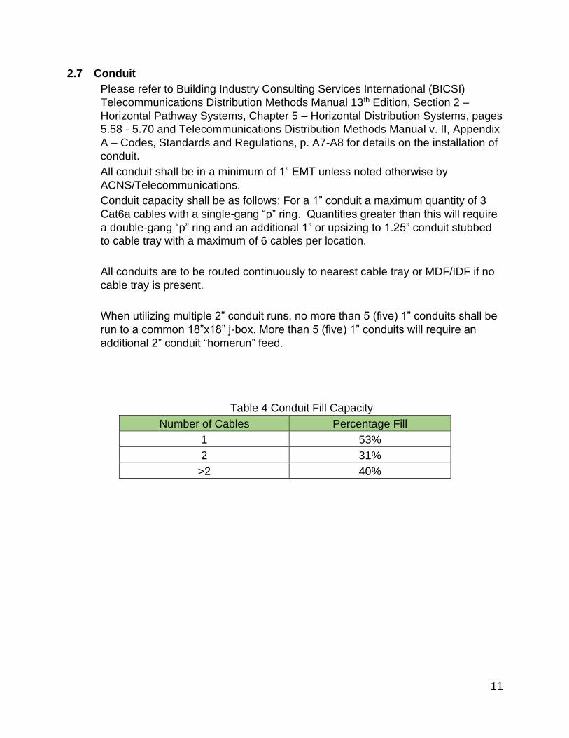
2.7 Conduit
Please refer to Building Industry Consulting Services International (BICSI)
Telecommunications Distribution Methods Manual 13th Edition, Section 2 –
Horizontal Pathway Systems, Chapter 5 – Horizontal Distribution Systems, pages
5.58 - 5.70 and Telecommunications Distribution Methods Manual v. II, Appendix
A – Codes, Standards and Regulations, p. A7-A8 for details on the installation of
conduit.
All conduit shall be in a minimum of 1” EMT unless noted otherwise by
ACNS/Telecommunications.
Conduit capacity shall be as follows: For a 1” conduit a maximum quantity of 3
Cat6a cables with a single-gang “p” ring. Quantities greater than this will require
a double-gang “p” ring and an additional 1” or upsizing to 1.25” conduit stubbed
to cable tray with a maximum of 6 cables per location.
All conduits are to be routed continuously to nearest cable tray or MDF/IDF if no
cable tray is present.
When utilizing multiple 2” conduit runs, no more than 5 (five) 1” conduits shall be
run to a common 18”x18” j-box. More than 5 (five) 1” conduits will require an
additional 2” conduit “homerun” feed.
Table 4 Conduit Fill Capacity
Number of Cables Percentage Fill
1 53%
2 31%
>2 40%

Powers 12
2.8 Installation of Cable Trays
Install cable trays with space to permit access for installing the cables. Clear
space shall be provided above the top rail equal to the loading depth but not less
than 12 inches. Provide lateral clearance of 24 inches on at least 1 side of the
trapeze hung tray. CSU prefers aluminum ladder type cable tray with 9” spacing
on rungs. All cable trays must be trapeze hung. The use of wire baskets is
discouraged. If wire baskets are to be used, please contact the
ACNS/Telecommunications Contact, Table 1, to discuss installation
requirements.
In the event of an unforeseen obstacle requiring the cable tray to be transitioned
from tray to conduit, the conduit shall be equal to or greater than the square
inches of tray being replaced.
Every effort should be made to minimize changes in elevation or direction in the
cable tray. If it becomes necessary to do so, those changes shall be
accomplished by using factory manufactured and approved “UL” listed
connections for bonding purposes.
All components within the cable tray system shall meet grounding and bonding
requirements.
Cables shall be pulled with no more than a 25-pound pull force applied at any
time during installation.
Cable trays are to be installed early enough in the process to minimize disruption
to the trays during subsequent construction.
2.9 Testing and Reporting of Test Results
All cable installed shall be tested using a calibrated Fluke Series DSX-5000
Tester or higher version in accordance with the latest EIA/TIA 568 standards,
and the results recorded on a separate USB stick for each building and provided
to ACNS/Telecommunications.
The ACNS/Telecommunications contact from Table 1 shall be notified prior to
any testing so that the representative or designate may be present during the
testing. If the circuit testing is conducted in the absence of the University
representative or designate, then the University may request a retest with the
University representative present at the tester’s expense.

Powers 13
2.10 Systimax Certification
CSU requires that upon completion and testing of each building/project, Systimax
certification be obtained. The Telecommunications contact person is responsible
for coordinating the Systimax certification and facilitating any remedies. Please
refer to Table 1 – Contacts for the name of the ACNS/Telecommunications
contact.
2.11 As-Builds
Upon completion of termination and testing, as-build drawings of all drops shall
be provided within four weeks for each major phase of work; such as 1) floors, 2)
wings, or 3) entire buildings. The as-build drawings shall be provided in AutoCAD
version 2013 or higher format. These files are to be on a separate USB stick for
each building.
2.12 Drop (Circuit) Labeling
Each drop installed shall be labeled per CSU labeling scheme. Each drop shall
be labeled on the front of the jack faceplate, on the patch panel in the IDFs or
MDF, and on both ends of the cable.
2.13 Labels
Four labels per fiber cable, two for the cable and two for the fiber patch panel,
shall be prepared for all fiber cables. The University may elect to install the
labels.
2.14 Invasive Work
Invasive work (e.g., core drilling, hammer drilling or work that is noisy, dusty, etc.)
shall be conducted during off-business hours. Other work shall be coordinated
with the University designated representative (e.g., to pull cables during off-
hours), and these arrangements shall be determined by mutual agreement.
2.15 Scheduling for the Pulling of Cable
ACNS/Telecommunications crews will pull low voltage cable inside the building,
terminate it at the specified wall jacks, test and certify the cable. To do this
work, the contractor will need to coordinate with ACNS/Telecommunications (see
Table 1 "Contacts") to ensure cable work is scheduled and complete prior to the
installation of the ceiling grid. This will allow easy access to the cable trays and
ensure that ACNS/Telecommunications crews do not damage the ceiling grid. If
the ceiling grid is installed prior to cabling work, ACNS/Telecommunications will
not be responsible for any damage to the grid and will begin using contingency
funds to pay for the extra labor expense.

Powers 14
Powers 15
3 Communication Rooms
3.1 General Provisions
ACNS/Telecommunications room space, MDF and IDFs shall be dedicated to the
telecommunications function and related support facilities. Equipment not related
to the support of the ACNS/Telecommunications functions shall not be installed,
passed through, or entered in the telecommunications rooms without review by
ACNS/Telecommunications and consideration in the sizing of the space,
environmental requirements, etc. Such equipment should be installed in the EF.
In rare cases where the project manager and ACNS/Telecommunications agree
to host equipment from a non-CSU entity and that entity desires unsupervised
access to the communication room, the project must provide for: 1) Cardkey
access on the communication room door; 2) locking cabinets for CSU equipment;
3) Any other security arrangement deemed necessary by ACNS/Telecom.
ACNS/Telecommunications CANNOT install equipment in communications
rooms prior to the completion of the following items; (a) permanent dedicated
power, (b) proper grounding and lighting, and (c) secure permanent door and two
keys provided to the Telecommunications Contact. ACNS/Telecommunications
REQUIRES a minimum of three (3) weeks from the completion of the
aforementioned items until the service data for the following services; (a) elevator
telephones, (b) fire alarm(s), (c) door security, (d) environmental controls, and (e)
voice, data and/or video services.
ACNS/Telecommunications strongly recommend that early in the design phase
all parties desiring to install equipment in the MDF and/or IDFs be collectively
engaged to discuss placement of equipment and determine size requirements for
the communications rooms including any servers or equipment to be mounted in
the rooms. Signatures and permission must be obtained in advance for any non
ACNS/Telecommunications/Facilities operated equipment to be mounted in the
communication rooms ("ACNS/Telecommunications Communications Room
Installation Agreement"). Forms are available via ACNS/Telecommunications
contact listed in Table 1.

Powers 16
3.2 Main Distribution Frame (MDF)
ACNS/Telecommunications shall provide customized communication room
designs based on the requirements of each project. Please contact the
Telecommunications Contact Table 1 page 3.
The following are general guidelines in the absence of a custom communications
room design.
Buildings shall have an MDF where voice, video and data enter the building. The
MDF also serves as the distribution point for voice, video and data and shall be
secure to protect the integrity of these systems, particularly E911 services.
Grounding and bonding shall be provided in the MDF that includes bonding to
equipment racks, cable trays and telecommunications conduits in strict
accordance with the ANSI/TIA 607 standard, the most current edition NEC, and
as a reference BICSI DD 120-Grounding Fundamentals for TELCO Facilities,
Chapter 4 Telecommunications System Grounding and extended to all IDF as
described therein. All penetrations of the MDF envelope shall be fire-stopped.
In buildings of size 5,000 square feet or greater, a secure room dedicated to
telecommunications, shall be provided for the MDF. In smaller buildings, a
secure wall-mounted Hoffman box may be an option in lieu of a separate,
dedicated room.
ANSI/TIA 569 shall be strictly observed for the MDF, such as not sharing with
electrical rooms, sources of electromagnetic interference (EMI), radio frequency
interference (RFI), perimeters (no false ceilings), limited access (i.e., security),
HVAC, lighting and electrical.
MDF Power Requirements:
MDF shall be provided with four dedicated and one general use circuits.

Powers 17
Two 20 amp, 120 volts NEMA 5-20 terminated on double duplex outlets,
and two 30 amp, 208 volts NEMA L6-30 outlet on the wall adjacent to the
telecommunications racks. The general use outlet shall be near the door for ease
of access – these locations shall be determined in consultation with
ACNS/Telecommunications.
Provisioning of power and receptacles for non-ACNS/Telecommunications
equipment requiring power installed in the MDF or IDFs is the responsibility and
at the expense of the entity responsible for the equipment. No extension cords
are acceptable whether they be loose on the floor or tied to the infrastructure.
No piping (sewer, water or other fluid), ductwork, mechanical equipment, or
power cabling or similar shall be allowed to pass through a MDF that is not
associated with the communications services in that specific MDF. Switched
lighting of 50-foot candles shall not be sourced from the same circuit as the
telecommunications equipment.
MDFs (entrance facilities) shall be environmentally conditioned to accommodate
network equipment loads up to 10,000 BTU/hr. Temperature in MDFs (entrance
facilities) shall not exceed 80°F.
The MDF shall have 3/4" A/C fire treated plywood backboards to be installed on
all walls, 8’ high starting 3.5” from floor and painted with matte white paint. All
fire-rated labels must be masked off prior to painting and left clearly visible.
The MDF serves as the fiber distribution point for the building and houses the
network switches.
In a multi-story building, there should be a Telecom room on each floor, centrally
located. CSU requires that the MDF be located on the ground floor. All data cable
runs are to be limited to 90 meters in length.
The MDF shall be large enough to accommodate at least two 7’x19” relay racks
and 3 - 12” vertical organizers; one rack for the building fiber and copper
distribution and the other for the building data switches and associated UPS. The
MDF shall also accommodate the voice and video distribution systems which
may be wall or rack mounted.

Powers 18
All raceways into the MDF envelope shall be a fire barrier pathway.
Table 5. MDF Sizes
Building Size (ASF) MDF Size
(Length x width - ft)
Less than 5,000 Hoffman Box
5,000 to 10,000 10x8
10,000 to 50,000 10x12
50.000 to 100,000 12x12
100,000 to 150,000 14x14
150,000 to 200,000 14x16
Doors shall open outward and adhere to all fire codes. It may be necessary to
install double opening doors for this purpose. Self-closing locksets shall be used
to ensure doors are secure upon their closure.
Powers 19
3.3 Intermediate Distribution Frame (IDF)
ACNS/Telecommunications shall provide customized communication room
designs based on the requirements of each project. Please contact the
ACNS/Telecommunications Contact Table 1.
The following are general guidelines in the absence of a custom communications
room design.
Grounding and bonding shall be provided in the IDF that includes bonding to
equipment racks, cable trays and telecommunications conduits in strict
accordance with ANSI/TIA J-STD-607-A-2002 standard, the most current edition
NEC, and as a reference BICSI DD 120-Grounding Fundamentals for TELCO
Facilities, Chapter 4 Telecommunications System Grounding and extended to all
IDFs as described therein. All penetrations of the IDF envelope shall be fire-
stopped.
ANSI/TIA 569 shall be strictly observed for the IDF, such as not sharing with
electrical rooms, sources of electromagnetic interference (EMI), radio frequency
interference (RFI), perimeters (no false ceilings), limited access (i.e., security),
HVAC, lighting and electrical.
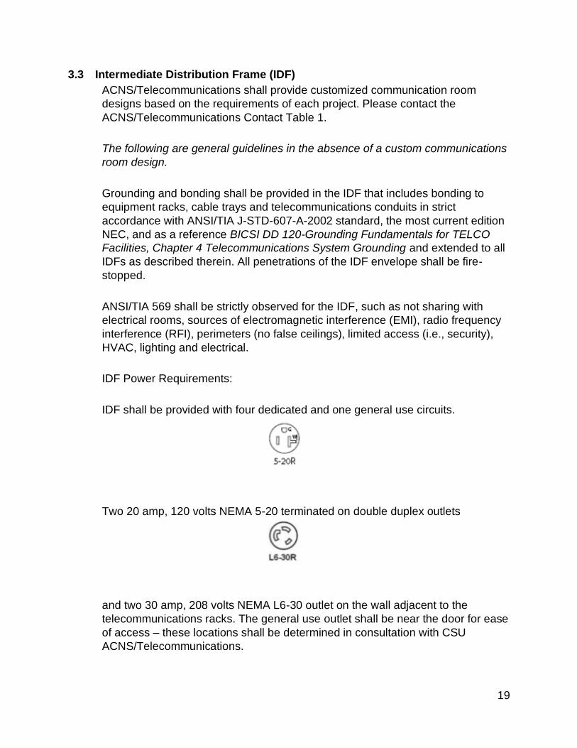
IDF Power Requirements:
IDF shall be provided with four dedicated and one general use circuits.
Two 20 amp, 120 volts NEMA 5-20 terminated on double duplex outlets
and two 30 amp, 208 volts NEMA L6-30 outlet on the wall adjacent to the
telecommunications racks. The general use outlet shall be near the door for ease
of access – these locations shall be determined in consultation with CSU
ACNS/Telecommunications.

Powers 20
Provisioning of power and receptacles for non-Telecommunications/ACNS
equipment requiring power installed in the MDF or IDFs is the responsibility and
at the expense of the entity responsible for the equipment. No extension cords
are acceptable either “loose” on the floor or tied to the infrastructure.
No piping, ductwork, mechanical equipment, or power cabling or similar shall be
allowed to pass through an IDF that is not associated with the communications
services in that specific IDF. IDFs shall be supplied with 50 foot-candle of
switched lighting, which shall not be sourced from the same circuit as the
telecommunications equipment.
Each floor shall have a dedicated IDF. IDFs shall be environmentally conditioned
to accommodate network equipment loads up to 7,000 BTU/hr/. Temperature in
IDFs shall not exceed 80°F.
The IDF shall have 3/4" A/C fire treated plywood backboards to be installed on all
walls in the IDF, 8’ high starting 3.5” from floor and painted with matte white
paint. All fire-rated labels must be masked off prior to painting and left clearly
visible.
IDFs shall be located at points that minimize the runs of the data network to the
end user, typically in the center of wings of buildings. Data cable runs are to be
limited to 90 meters, and this may affect placement of the IDF or require
additional IDFs (telecommunications rooms) to be added.
IDFs shall be sized such that there is ample room to install racks to house the
equipment. The IDF shall be sized to accommodate a minimum of two vertical
7'x19" relay racks and 3 - 12” vertical organizers: one for the fiber, an IDF switch,
and UPS; and another for edge network switches. Ideally, there shall be 48” of
space on each side of the rack lineup. Preferably, the MDF and IDFs shall be
vertically stacked within the building.
IDFs shall be sized to accommodate all connections that may potentially be used
from that room. In a typical scenario, an IDF would serve an area of
approximately 10,000-15,000 Assignable Square Feet (ASF), depending on
density of connections deployed from the IDF
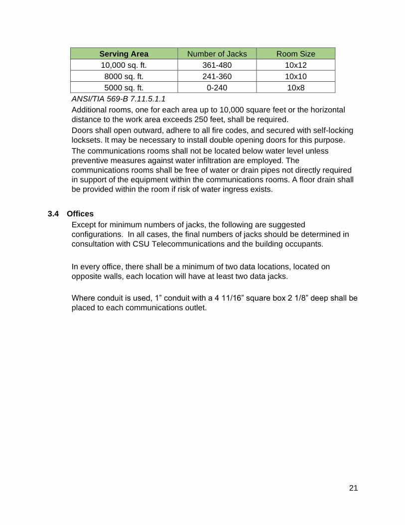
Table 6. IDF Specifications
Powers 21
Serving Area Number of Jacks Room Size
10,000 sq. ft. 361-480 10x12
8000 sq. ft. 241-360 10x10
5000 sq. ft. 0-240 10x8
ANSI/TIA 569-B 7.11.5.1.1
Additional rooms, one for each area up to 10,000 square feet or the horizontal
distance to the work area exceeds 250 feet, shall be required.
Doors shall open outward, adhere to all fire codes, and secured with self-locking
locksets. It may be necessary to install double opening doors for this purpose.
The communications rooms shall not be located below water level unless
preventive measures against water infiltration are employed. The
communications rooms shall be free of water or drain pipes not directly required
in support of the equipment within the communications rooms. A floor drain shall
be provided within the room if risk of water ingress exists.
3.4 Offices
Except for minimum numbers of jacks, the following are suggested
configurations. In all cases, the final numbers of jacks should be determined in
consultation with CSU Telecommunications and the building occupants.
In every office, there shall be a minimum of two data locations, located on
opposite walls, each location will have at least two data jacks.
Where conduit is used, 1” conduit with a 4 11/16” square box 2 1/8” deep shall be
placed to each communications outlet.

Powers 22
3.5 Grounding and Bonding
In general, all grounding and bonding to adhere to current BiCSI
Telecommunications Distribution Methods Manual.
The telecommunications bonding backbone (TBB) shall be a copper conductor.
The minimum TBB conductor size shall be a No. 6 AWG. The TBB should be
sized at 2 kcmil per linear foot of conductor length up to a maximum size of 3/0
AWG. The TBB may be insulated. If the TBB is insulated, the insulation shall
meet the fire ratings of its pathway. The sizing of the TBB is not intended to
account for the reduction or control of electromagnetic interface. (See
appendices H and I.)
Table 7. TBB Sizing
TBB length linear ft. TBB Size (AWG)
Less 13 6
14 – 20 4
21 – 26 3
27 – 33 2
34 – 41 1
42 – 52 1/0
53 – 66 2/0
> 66 3/0
ANSI/TIA J-STD-607-A 5.4.4.1
All equipment shall be bonded to each rack’s supplied bus bar in addition to not
utilizing the power cord as the specified ground.
Lightning/Surge protection is required for all OSP cabling entering CSU facilities

Powers 23
4 Riser/Building Backbone Infrastructure
The building backbone consists of fiber optic cable to support data, voice and
video applications as well as copper cabling to facilitate any required analog
services.
The infrastructure for the building backbone cabling shall consist of conduit
between the MDF and each IDF where the run is vertical, or ladder racks (not
hooks or rings) where the run is horizontal. Where conduits are run, separate
conduits shall be used for copper cables and fiber cables. However, where runs
are horizontal and ladder racks are used, both types of cables shall be run in a
ladder rack.
EIA/TIA 569 shall be observed for the building backbone pathways. Conduits
shall be sized to be no more than 40% full by volume. Long-radius metal sweeps
shall be used instead of 90° fittings. No more than 180 degrees of bends
between pull points shall exist in conduits without inclusion of a readily
accessible and adequately sized pull box, the location of which shall be clearly
marked on drawings. In situations where cable tray, conduit, or sleeves extend
outside the MDF/IDF into occupied portions of the building, they shall be fire-
stopped.
Both single-mode and 50-micron OM4 multimode fiber cable shall be run
between the MDF and each IDF in a star configuration. At minimum, there shall
be no less than 12 single-mode and 12 multimode fibers installed. A higher fiber
optic pair count shall be permissible in consultation with
ACNS/Telecommunications. Fiber cables shall be run in conduit or in innerduct if
cable tray distribution method is selected. The fiber count depends on the
number of data jacks in each IDF. One pair of multimode fibers is required for
every 48 active data jacks with a 30% allowance for growth. Each number shall
be rounded up to the next integer. Table 8 below illustrates fiber counts for a
variety of situations:
Table 8. Multimode Fiber Counts
Number of active
data jacks
Base fiber
count
30%
allowance Total fiber count
96 2 pair 1 pair 3 pair
144 3 pair 1 pair 4 pair
240 5 pair 2 pair 7 pair
336 7 pair 3 pair 10 pair
Powers 24
Note that fiber bundles are available only in certain numbers of pairs. As an
example, consider the example where bundles with 12 fibers (6 pairs) are used.
For the second example above, 144 active jacks, one 12-count (6-pair) cable
would be required. For the last example above, 336 active jacks, two 12-count
cables would be required. On a typical installation of a composite 12 single mode
and 12 OM4 multi-mode fibers installed between the MDF and IDF a minimum of
two single mode fibers shall have factory terminated Angle Polished Connectors
(APC) to a accommodate video transfer.
Single-mode fiber shall be pre-tested with an Optical Time Domain Reflectometer
(OTDR) at 1310 nm & 1550 nm, upon cable delivery.
Multimode fiber shall be tested post installation at 850 nm and 1300 nm.
A bidirectional end-to-end test shall be conducted at dual wavelength for each
fiber installed.
Prior to acceptance by the University, the OTDR and end-to-end test shall be
randomly sampled and retested by the University.
Test results shall be electronically documented and submitted to the
ACNS/Telecommunications contact from Table 1 on a USB stick.
Cable ladder racks shall be hung in a manner that ensures a minimum of 12"
vertical clearance and 18" horizontal clearance on at least one side to allow for
access to the ladder rack for cable installation and maintenance. Mount cable
ladder racks 7’ 6” AFF (above the finished floor) to be accessible by cable
handlers using standard 6-foot ladders. Transitions where changes in height are
unavoidable shall be gradually sloping. The cable ladder rack shall be routed so
as not to interfere with installation of other systems or access to those systems
for maintenance. Coordination with other systems shall be maintained so that
where these systems traverse above or below the ladder rack, access shall not
be blocked or interfered with. Cable ladder racks shall not pass through firewalls.
Instead, the ladder rack shall stop on either side of the firewall and be
interconnected via multiple fire barrier pathways passing through the firewall. The
bottom of these pass-through devices shall be aligned with the top of the cable
ladder to ensure proper cable support and unrestricted passage. These pass-
through conduits shall be no more than 40% full.

Powers 25
5 Building Entrance Infrastructure
5.1 General Provisions
At the University, telecommunications typically enter the building into the Main
Distribution Frame or MDF. Thus, generally at the University, the Building
Entrance and the MDF are one and the same. In certain venues,
ACNS/Telecommunications may require the addition of an Entrance Facility to
accommodate an interface between non-CSU service providers.
Buildings are required to have physically diverse paths to the campus fiber
infrastructure from the MDF.
EIA/TIA 569 shall be observed for the building entrance. Underground conduits
entering a building shall be dedicated for the exclusive use of
ACNS/Telecommunications and no more than 25% full by volume.
ANSI/TIA 758-B section 4.3 shall be observed in providing diverse entrance
points and routes.
ACNS/Telecommunications may request removal of unauthorized cable(s) within
ACNS’/Telecommunication’s entrance conduits. Copper and fiber cables shall be
brought into the building in separate conduit systems. There shall be no more
than a total of 180 degrees of bends between pull points, using only large radius
PVC coated GRC or fiberglass sweeps, shall be used in conduit runs between
pulling points.
5.2 University Policy Governing Entrance Infrastructure
ACNS/Telecommunications must be contacted, refer to Table 1 – Contacts,
during the early planning stages for new constructions or remodels that will
require new or modification of entrance infrastructure.

Powers 26
6 Outside Plant Infrastructure
6.1 Introduction and Project Conditions
The following specifications govern services contracted by Colorado State
University (CSU). Contractors shall fully adhere to these specifications, unless
the University designated representative authorizes a waiver or modification in
writing.
The contractor shall be responsible for conducting all potholing and/or locates of
all utilities along the prescribed route. The contractor is responsible for contacting
UNCC at 811. In addition, it is the contractor’s responsibility to ensure that all
utilities are located including CSU’s utilities. Facilities Management telephone
number is 970-491-0077.
Locate and protect existing utilities and other underground work in a manner that
will insure that no damage or service interruption will result from excavating and
backfilling.
When applicable, the contractor shall be responsible for acquiring all relevant
permits for street, alleys, easements, utility corridors, etc. from the City of Fort
Collins.
When utilities are damaged, the contractor shall immediately contact CSU
Telecommunications (970-491-5881) and CSU Facilities Management (970-491-
0077).
The contractor agrees to remedy all defects identified by CSU during the final
inspection of the contractor’s work. The scheduling of the remedies shall be
approved by CSU. The contractor shall be responsible for obtaining a final work
acceptance signature, from the University designated representative, on a
mutually agreed upon “punch list” to indicate acceptance of the contractor’s work
by CSU.
The contractor is responsible for adhering to all applicable industry and personal
safety standards, including, but not limited to OSHA standards.
The contractor shall be responsible for providing an as-build drawing. Please
refer to As-Builds section in Chapter 2 for details. However, for outside plant
infrastructure projects, the contractor in addition shall illustrate route(s), depth
and benchmark measurements from existing landmarks and fixtures.
Powers 27
The contractor shall report on the progress of the work to the
ACNS/Telecommunications contact from Table 1 on a mutually agreed-upon
schedule.
6.2 Landscaping, Irrigation Systems, Site Protection and Excavation
Contact CSU Facilities Management at 970-491-0077 for all requirements.
6.3 Directional Boring Specifications
Materials - Installed two-inch (2”) inner duct, quantity to be determined. The inner
duct shall have a No. 12 UF type tracer wire installed outside the duct along the
entire path of the duct. The ACNS/Telecommunications contact from Table 1
shall approve any deviation.
Conduit shall only have new 1800 lb. Sequential Mule Tape, supplied and
installed by the contractor, in each duct without knots and splices. The mule tape
shall be exposed at least six feet (6’) for aiding in tying on to cable. Polyrope
shall not be accepted within the duct.
Installation - The inner duct shall be installed a minimum of forty-eight inches
(48”) in depth. The inner duct shall have a gradual 2” sweep into the J-box or a
location marked by CSU prior to start of work (e.g., manhole). The inner ducts
shall have duct plugs installed and secured around cable to prevent any debris
from entering the conduit. All vacant inner ducts shall have a duct plug installed
and secured.
Building Entrance Only: Inner ducts exposed on the exterior of a building shall
have installed GRC fittings to National Electrical Code (NEC) specifications
attached for building entry conduit and approved by CSU. Plenum and non-
plenum areas may require additional consideration.
Splices, where applicable, shall be dug to the depth of the bore and be in a
straight line with the two (2) adjoining bores.
Manholes - shall be pumped and cleaned before and after work is completed.
The manhole shall have sufficient racking drilled and mounted for cable
attachment and service coil support. CSU shall be consulted for determination of
service coil length and racking requirements. Inner duct entering through the
manhole or concrete foundations shall be core drilled and have link seals
installed.
Traffic Control - The contractor shall be responsible for providing traffic control
commensurate with the requirements of the work it is conducting, and adheres to
all municipal, State, and Federal guidelines and standards.

Powers 28
6.4 Trenching
Materials - The contractor shall coordinate with the ACNS/Telecommunications
contact from Table 1 and they shall specify and approve the vault(s) for each
project
The contractor shall install a four-inch (4”) Yellow Caution Tape labeled “Caution”
twelve inches (12”) from the bottom of the trench.
Conduit duct shall have a No. 12 UF type tracer wire installed outside the
conduit. The ACNS/Telecommunications contact shall approve any deviation.
Conduit shall have only new 1800 lb. Sequential Mule Tape, supplied and
installed by the contractor, in each duct without knots and splices. The mule tape
shall be exposed at least six feet (6’) for aiding in tying on to cable. Polyrope
shall not be accepted within the duct.
Installation of Conduit and Vault - All conduits shall be installed a minimum of 48”
in depth. When PVC conduit is placed in a trench, PVC coated GRC or fiberglass
large radius sweeps shall be used.
Contractor shall ensure that the integrity of the vault is retained throughout its
installation. To the extent necessary, the contractor shall internally brace the
vault to ensure its integrity throughout installation and soil compaction.
Each newly installed or reinstalled vault shall be excavated 2’ deeper in order to
accommodate for 2’ 1” minimum aggregate of rock to bring the vault to grade and
maintain adequate drainage.
Each newly installed or reinstalled vault shall have a 3M 1401 – XR 4” Ball
Marker installed inside the vault.
Vaults shall NOT be drilled or penetrated without prior approval.
Vaults shall be sized to neatly accommodate copper and/or fiber optic cables and
service coils.
Conduits shall gradually sweep in below the bottom of the fiberglass vaults.
Ducts shall have duct plugs installed and secured around cable to prevent any
debris from entering the conduit.
6.5 Steam Tunnel Cable Installation
Contact CSU Facilities Management at 970-491-0077 prior to commencing any
work in the University steam tunnels.

Powers 29
7 Network Switches
7.1 General Provisions
Buildings shall be supplied with a building data switch and sufficient edge
switches to provide network access to current users. ACNS/Telecommunications
shall be responsible for specifying the specific brand and model for network
equipment. Using this standard equipment will ensure that the network
equipment is compatible with campus backbone network equipment. This is the
only way to ensure that performance, advanced features such as Quality of
Service (QoS), multicast, security, and manageability, will exist and interoperate
with campus networking infrastructure. All switches and related network
equipment must adhere to CSU’s Network Operations Policy
http://policylibrary.colostate.edu/policy.aspx?id=718
7.2 General Switch Standards:
• If more than two 1U switches are required to provide sufficient connectivity, a
chassis-based switch shall be used in place of 3 or more 1U switches.
• All switches are to provide 10G uplinks capability.
• All switches are to provide 1G connections on all edge ports.
• All switches are always to provide PoE+ on all ports .
• In general, a 70% activation rate is to be assumed, that is a 30% allowance
shall be made for ports that are not initially activated.
• Switches shall meet all operational standards as listed in Appendix A.
• Switches housed in outdoor locations shall be enclosed in a Hoffman box with
environmental controls of heating and cooling.
• Temperatures are not to exceed 80 degrees F nor go below 32 degrees F.
• All switches to be mounted in MDF/IDFs or secured Hoffman type boxes.
Switches are not to be installed on desktops, in rooms, labs or other non-
communication rooms. Switches installed outside of formal communication
rooms are supported on a time and materials basis.
• Network devices not spec’d, configured, installed and monitored by
ACNS/Telecom and connected to the campus network must be approved in
writing and are supported on a time and materials basis.
Powers 30
7.3 MDF Switches Additional Standards:
• The primary MDF switch is to connect to the campus core with two 10G
connections on disparate routes out of the building.
• The primary MDF switch is to have redundant power supplies.
• MDF switches with multiple power supplies are to be able to provide power on
all ports at PoE+ levels even if one power supply fails.
• Primary MDF chassis-based switches are to have the first two modules
reserved for central services and uplinks. User data jacks are not to be
terminated out of these ports.

Powers 31
8 Wireless Access Points and Devices
8.1 General Provisions
• "Wireless access points" are defined as any device adhering to the IEEE
802.11 WiFi specifications for network access.
• "Wireless devices" are all other devices operating in the same spectrums as
the IEEE 802.11 WiFi specifications, i.g.: 2.4Ghz, 5GHz
• All new construction and remodels should receive input from
ACNS/Telecommunications regarding how the project will affect current
wireless signals.
• All new construction and remodels should receive input from
ACNS/Telecommunications regarding any necessary adds/moves/deletes from
existing wireless infrastructure.
• Two cat6a cables shall be provided to every access point location.
• PoE+ will be provided over each of the cat6a cables to wireless access points.
• ACNS/Telecommunications will specify the type, count and location of all
access points.
• No additional access points or devices acting as an access point can be
connected to the campus network per campus IT Security Policy.
• ACNS/Telecommunications must approve the use of any wireless device that
will connect into the data network. This is to ensure proper balance of devices
within the available spectrums.
• ACNS/Telecommunications will specify locations on DD prints for locations of
access points. It is the contractor’s responsibility to ensure that these access
points are placed within a 1’ diameter of the specified location. If the access
points are not placed as specified, it is the contractor's responsibility to move
and pay for putting the access point in the position specified.
• Wireless access points cannot be installed prior to building completion as
drywall dust blocks the heat exhaust fans causing them to overheat.
• In order to properly quote the cost for wireless access point,
ACNS/Telecommunication need to know: o The Room Size o The Ceiling Height o Description of room usage, e.g.: classroom, conference room, lab space, maximum
occupant count
Powers 32
8.2 Wall Mounted Wireless:
• Provide a recessed 4-11/16 deep electrical box with a 2-gang plaster ring
• Mount box with ring flush to finished surface
• Mount wireless box minimum 7’ to maximum 12’ above finished floor
• Mount wireless box no less than 1’ from center of box to ceiling, adjacent walls,
ducts, plenums or other permanent obstructions
• Mount box vertical (plaster ring mounting holes top to bottom)
• See Appendix C
8.3 Suspended Ceiling Mounted Wireless:
• Provide a 4-11/16 deep electrical box above ceiling tile with a cover plate
• Insure minimum 1’clearance from center of box to any obstructions
• If ceiling height exceeds 15’ above finished floor mount wireless on nearest
wall rather than ceiling. Notify ACNS/Telecommunications of change since this
will require a different type of wireless access point.
• ACNS/Telecommunications needs minimum 30-day notice of ceiling grid and
tile selection
• See Appendix D
8.4 Open Ceiling Wireless:
• Provide 4-11/16 deep electrical box no higher than 14’ above finished floor.
• If ceiling height exceeds 15’ above finished floor mount wireless on nearest
wall rather than ceiling. Notify ACNS/Telecommunications of change since this
will require a different type of wireless access point.
• Insure minimum 1’clearance from center of box to any obstructions
• Wireless access points shall be located below any building duct work, piping
and other obstructions and in no case higher than 12’ above finished floor
height.
• See Appendix E

Powers 33
8.5 Outdoor Mounted Wireless:
• Provide a 4-11/16 deep electrical box with a ground
• Insure minimum 2’clearance from center of box to any obstructions
• Provide a weatherproof cover plate
• Mount box with cover plate flush with finished surface
• Lightning/Surge protection is required
• See Appendix F
8.6 Hard Lid Ceiling Mounted Wireless:
Provide a 4-11/16 deep electrical box with a 2-gang plaster ring mounted flush to
finished surface
Insure minimum 1’clearance from center of box to any obstructions
If ceiling height exceeds 15’ above finished floor mount wireless on nearest wall
rather than ceiling. Notify ACNS/Telecommunications of change since this will
require a different type of wireless access point.
See Appendix G
9 VOIP
Phone service for University locations is provided by ACNS/Telecommunications.
All installations are to support current VOIP standards. Consultation with
ACNS/Telecommunications contact as listed in table 1 is required to ensure
compliance with all current standards. Contractor is required to provide drawing
to the ACNS/Telecommunications contact as listed in table 1 so comments can
be provided for the DD phase.
10 TV/Video
Network electronic and video equipment specifications shall be respectively
provided on a case-by-case basis to ensure that the latest technology and lowest
price is applied to the project. Please refer to the contact in Table 1.

Powers 34
11 Emergency and Inter/Intra Building Life and Safety Infrastructure
Colorado State University has contracted with Rave Wireless for Rave Alert.
Rave Alert is an emergency text notification service that delivers emergency
notification to subscriber’s cellular devices. Emergency text notifications will be
composed by CSU emergency/police and/or public relations personnel in case of
an emergency on campus and/or an outside event that affects the campus
community. Rave Alert is an optional subscription service for registered students
and faculty and staff.
12 Classroom Standards
12.1 Introduction
Colorado State University seeks to create world-class academic spaces that
enable learning of the highest caliber. The following document encapsulates
current thinking about academic technology that delivers the best in-person and
online learning environments. CSU Classroom Support Services should be
consulted at all phases of the design and construction of new academic spaces
for interpretation of the standards defined below, and to pursue variation for
innovative and creative approaches to the application of technology in the
learning environment.
CSU Classroom Support Services maintains a current list of defined hardware
standards, which are updated regularly as technology evolves. While this
document reflects defined standards and is updated frequently, the hardware
standards should be considered as always up to date regardless of the RFP
process and requirements.
Hardware Standards: See the Classroom Support Services web site:
https://www.acns.colostate.edu/classroom-support-services/

Powers 35
12.2 Description of General Assignment Classrooms
• CSU classrooms are designed with consistent characteristics to make it easier
for faculty to operate the classroom systems.
• Lecterns are two rack units wide with a Crestron touch screen mounted on the
top panel for control functions.
• The Crestron system provides controls for all AV equipment in the room.
• Cables for laptop connection, network and any other equipment are routed
through a cable nook inset into the top surface of the lectern.
• For rooms seating 50 or more, a raceway must be provided from the lectern to
a practical PTZ camera placement location suitable for a lecture capture
camera.
• Lecture capture rooms should be equipped with ceiling mounted microphones.
• Suspended lighting fixtures are mounted clear of the sight lines for projectors
and cameras.
• All AV equipment with a network port is connected to the CSU network.
• All projectors are laser type.
• Whiteboards are installed on the front wall and sometimes also the side walls
of classrooms. There must be a substantial amount of whiteboard space
available to teachers even when the projection screens are fully lowered.

Powers 36
12.3 Large Classroom, 100+ Seats
• One or more motorized 16:10 powered projection screens, laser projector(s),
ceiling PA speakers, ceiling and wireless microphones, lectern, touch screen
control, LED monitors where appropriate. All large classrooms are lecture
capture rooms; see section 1.6 for more information.
• Equipment for the Large classroom:
• All video monitors must capable of at least 1920 x 1200 resolution.
• Projectors must be laser, capable of at least 1920 x 1200 resolution. Control
via CAT6A cable.
• Data projector must use industry standard (typically Cat6A STP) cable to the
switcher’s HDBaseT-compatible port.
• Larger rooms often have 2 (two) projectors with ability for the user to put
matrix-switched different content on each.
• Where whiteboards are located behind screens, programming allows user to
power off each projector and raise the screen individually to use the
whiteboard. Control also allows user to raise and lower each screen
individually while leaving the projector powered on to illuminate the whiteboard.
• Projection screens are powered with housings recessed into the ceiling.
Screens actuate automatically with projector power and can be overridden
(retracted) via lectern-mounted touch panel control.
• A two-bay lectern houses the A/V equipment unless an A/V closet is used; in
that case, A/V controls, laptop connection, touch screen monitor, DVD player
and document camera must still be user-accessible and located on the lectern.
• Touch-screen monitor shall be mounted on the desktop with mount located
centrally on the lectern desktop to allow full range of motion. Mount shall be
adjusted to eliminate 360-degree rotation which can damage connecting cables
and monitor connectors.
• Monitor cable installation will include strain relief to protect the cables and the
monitor connections.
• Additional large screen (supplemental) monitors may be required around the
room for breakout group sessions. Need for monitors is determined on a room
by room basis in design phase.
• Each supplemental video monitor shall have a wireless presentation device,
and wall plate HDMI connections shall also be provided adjacent to each
monitor.
• Each supplemental video monitor shall be connected to the CSU Network.
• Each supplemental monitor output and input shall be routed to the room matrix
switcher to allow display of any source on or from any source to any display.

Powers 37
Display sources located in/on the lectern:
• Laptop (HDMI output and RJ-45 network connections are required)
• Document camera
• Blu-Ray player with wired network connection and
• Touch screen monitor for computer.
• Wireless connection device mounted inside lectern.
• Two CAT6A STP cables must be run from the lectern to a practical camera
placement location suitable for a PTZ camera.
• There will be one or more ceiling mounted digital microphones depending on
the size of the room.
• The lectern shall have one wireless microphone system; output is to be fed to
room PA and any recording or lecture capture system.
• Crestron DMPS unit with appropriate switching capacity for the equipment
installed, with Crestron touch panel mounted in lectern top.
Auditorium installations often use additional matrix switchers and audio
equipment. These installations require additional A/V rack spaces which are
normally provided in an AV closet location.

Powers 38
12.4 Medium Classroom: 50-100 Seats
• 16:10 powered projection screen, projector, touchscreen control on lectern,
ceiling speakers for playback. These rooms are to be lecture-capture ready,
with rough-in to support installation of PTZ cameras and ceiling-mounted
mircophones.
• All video monitors must capable of at least 1920 x 1200 resolution.
• Projectors must be laser, capable of at least 1920 x 1200 resolution. Control
via CAT6A cable.
• Data projector must use industry standard (typically Cat6A STP) cable to the
switcher’s HDBaseT-compatible port.
• Projection screen shall powered, with mount recessed in ceiling.
• Additional large screen (supplemental) monitors may be required around the
room for breakout group sessions. Need for monitors is determined on a room
by room basis in design phase.
• Each supplemental video monitor shall have a wireless presentation device,
and wall plate HDMI connections shall also be provided adjacent to each
monitor.
• Each supplemental video monitor shall be connected to the CSU Network.
• Each supplemental monitor output and input shall be routed to the room matrix
switcher to allow display of any source on or from any source to any display.
• A two-bay lectern houses the AV equipment.
• Crestron DMPS unit will be installed with appropriate switching capacity for the
equipment installed and Crestron touch panel mounted on lectern top.
• Wireless presentation device outputs shall be connected to the DMPS control
unit or matrix switcher for classroom display.
• Wireless microphone as specified above may be installed depending on
design.
• Ceiling microphone may be installed depending on design.
• PA speakers may be wall or ceiling mounted depending on room design.
If Medium classroom will have lecture capture, see lecture capture specifications.

Powers 39
12.5 Small Classroom: Fewer than 50 Seats
Specifications and equipment are same as medium classroom.
• Lecterns may not be used in some rooms that are small enough to double as
conference rooms; in those cases, the Crestron touch panel will normally be
placed on a table.
• No wireless microphone is needed in small classrooms unless lecture capture
is to be installed. If lecture capture is to be used in the room, a wireless QLX
series microphone (belt pack and lavaliere mic) and charger as specified above
are required.
If small classroom will have lecture capture, see lecture capture specifications.
12.6 Conference Rooms
• Most conference rooms seat 6-12 people and use a video flat panel rather than
a projector and screen. Standard video display is a wall-mounted video
monitor, 65” or larger, capable of at least 1920 x 1200 resolution.
• Lecterns are generally not used in conference rooms, but there are exceptions.
Check with CSU Classroom support to confirm.
• Crestron controls may be used if the amount of equipment to be installed
justifies it; this decision is made on an individual room basis.
• Regardless of the control system, there must be a means of turning displays on
and off and selecting display inputs without using buttons on the monitor or a
TV remote control.
• Connections to the monitor are generally routed via HDMI cable from the
conference table area to the monitor.
• The video monitor shall be connected to the CSU Network.
• If not routed through a floor box, at least two HDMI connections to the monitor
shall be enclosed in a floor box, or shall be provided on a wall plate adjacent to
the monitor.

Powers 40
12.7 All Rooms with Lecture Capture Function, Any Size:
• All rooms of any size should be roughed in for lecture capture. All rooms
seating more than 50 students shall be fully equipped with lecture capture
including microphones, camera and connections for digital recorder.
• Each room will have a PTZ camera mounted on the wall opposite the lectern
and presentation screen; the current model is
• A CSU network port and an AC power outlet shall be located next to the
camera.
• There shall be two CAT6A cables run between the camera mount and the
interior of the lectern, with HDMI transmitter/receiver units on one cable for the
camera signal.
• HDMI connections for the camera and for the video sent to the room projector
shall be provided inside the lectern.
• Program audio out from the DMPS unit to a 1/8” jack shall be provided for the
lecture capture device.
• The audio for the classroom and ceiling microphones must be programmed as
a constant/line level output, and must not mute to the lecture capture recorder
when the mic is muted in the room PA system.
• Lights in the room shall be mounted so as not to obstruct the camera view of
the presentation area.
• Ceiling mounted whiteboard lights are strongly discouraged. If they are used,
they must not hang down from the ceiling far enough to intrude into the camera
view or the projector image path.
12.8 Standard Lectern Design
Fixed lecterns are standard.
Classroom Lecterns
• When lecterns will be included in the design of a room, all AV control
equipment should be located within the lectern. Absent a lectern, AV
equipment should either be housed within an in-room equipment rack, or in a
dedicated AV systems room within allowable distance.
• CSU classrooms use a two rack-bay wooden lectern. Each room is configured
to be a user-friendly teaching station with an intuitive touch panel control
system designed with ease of control over media sources. Current lectern
suppliers: CSU Facilities or Growling Bear Company of Greeley CO: 1-970-
353-6964. Note: CSU is willing to consider accessible lectern options – please
consult with Classroom Support Services when specifying accessible lecterns
in designs.
• Lecterns will have a document camera mounted on the lectern top surface on
the right side. All lecterns will have removable panels (normally hinged doors
on the back side) to provide full access for service and maintenance.

Powers 41
• (See Section 7.1 for lectern electronics) Open spaces in any rack shall be filled
with blank metal panels to block user access to the interior rack space. If the
electronic equipment fills only one rack, the open side of the lectern shall be
equipped with rack rails on the front, to which a dark-tinted Plexiglas or
Polycarbonate panel covering the open enclosure shall be mounted. If the
electronic equipment also requires all or part of the second rack space, a full
front and back rack unit shall be installed with blank metal panels blocking
access to the unused rack spaces.
• No immovable objects may be located within 30 inches of the access doors or
within the access path for AV electronics to protect access for maintenance.
• Lecterns should be supplied with power and conduit to support data and AV
equipment connectivity directly from below the lectern.
12.9 Lectern Power and Data Requirements
• Power strips mounted to the rear of mounted equipment with surge protection
appropriate to the number of devices in the lectern should shall be provided in
each lectern. Two open and available powered outlets shall be provided for
future equipment installation.
• Two 4-Plex 120V AC outlets per side (on the inner walls of the lectern) coming
up through the rear of the lectern on flex from a combined 20amp circuit.
• One network cable shall be provided from the in-lectern switch to the top
surface of the lectern for user connectivity.
• Locks: lectern doors shall be equipped
• Three conduits with long radius sweeps shall be run to each podium, one
conduit for electrical power, one 2" conduit dedicated to central data and voice
communications, and one 1 1/4" conduit run from the podium to the digital
projector in the ceiling. The projector shall be centrally located below the
room’s false ceiling with the wiring and conduit permanently attached to the
ceiling structure. The projector will require one data jack. Electrical power shall
also be run to the ceiling-mounted projection system.
• A network switch will be specified by ACNS/Telecommunications for providing
data to devices in the podium.
Powers 42
12.10 Equipment Specifications
Display Input Sources – source switching specifications:
• The input signal path must handle a wide range of input resolutions up to
1920x1200.
Video Outputs:
• Minimum four HDMI outputs to serve room display, lecture capture,
touchscreen monitor on lectern, and one spare. All shall be HDMI scaled
outputs. More may be required depending on room design.
Audio Outputs:
• One line-level, variable stereo program output from analog and HDMI sources,
combined with variable mic output to power amp.
• Microphone –two outputs, wireless mixed and level controlled.
• One audio output for Echo360 Pod recorder with program audio integrated on
the HDMI video input to the recorder; one fixed mic audio output is required
with a 1/8” analog plug for the mic input on the Echo360 recorder.
• One additional fixed stereo program (mic plus all other devices) output for
lecture capture. This output will have program and mic audio.
• In lecture capture rooms, mute functions must not mute the program or the mic
audio feed to the lecture capture device.

Powers 43
12.11 Video, Data Projector and Lighting Specifications
Projector Design Specifications:
• CSU uses only laser projectors at wide screen (16:10) resolution. Wall displays
are usually 16:9.
• HDMI input must comply with the latest HDCP specifications.
• Ethernet connection is required on all projectors and wall displays.
• Crestron connection capability is required on all projectors.
• Projectors shall use the latest LCD or DLP technologies available on the
market, capable of 1920 x 1200 resolution. Wall displays are commonly 1920 x
1080; not 1920 x 1200.
Lighting
• Ceiling mounted whiteboard lights are strongly discouraged. If they are used,
they must not hang down from the ceiling far enough to intrude into the camera
view or the projector image path. They must also be capable of being turned off
from the lectern separately from all other room lighting.
• No suspended lighting in any classroom shall hang down from the ceiling far
enough to intrude into the camera line of sight or the projector image path. All
lights must be mounted at least 12 inches above the centerline of the projector
lens.
• Light controls shall be configured so that the row of lights closest to the display
screen can be controlled separately from the rest of the room lighting. Using
the 50/50 model of light control to enable 50% lighting or no light on that row of
lighting is appropriate.
12.12 Control System Specifications
Control Graphics
• CSU Classroom Support Services programs and supports classroom control
systems. Crestron products are required for all new installations and upgrades.
Control graphics shall conform to CSU design and visual practice.

Powers 44
The basic system in each lectern is comprised of:
• Controller – normally Crestron DMPS series with network port. If additional
controllers are needed, Crestron units are added.
• Touch Panel – TPW-760 – color touch panel.
• Integration capability with Crestron Roomview and Fusion must be included.
• Crestron program and Xpanel software for each room are to be supplied to
Classroom Support.
• CSU Crestron shut down code shall be included in the code for each room. It is
available from Classroom Support and shall be included in the code for each
room.
• Touch screen design samples: See Appendix J
• Current graphics and layout are available from CSU Classroom Support
Services.
• Contact CSU Classroom Support Services before finalizing touch screen
graphics or controls.
12.13 Control Design Specifications
• Programming files, Xpanel files and as-built diagrams for all installations
become property of CSU and shall be provided to CSU Classroom Support.
• All graphics, control screen layout and design, controls and functions in each
classroom must be reviewed and approved by CSU Classroom Support
Services before project signoff.
• Final control and touch panel files are to be given to CSU as part the project
signoff.
• Intuitive designs following CSU graphics practices are required, with user-
friendly ability to control the room without prior instruction.
• All classrooms should have the ability to dim the lights nearest to the projection
screens, with that control separate from the classroom lighting.
• All electric powered screens are to be controlled via the lectern touch panel.
• Projectors are controlled via RS232 or Ethernet – with run hours, filter hours
and reset for both provided in the programming and on the touch panel service
page.
• Source / switcher selections shall be controlled either by RS232 or Ethernet.
• Program audio shall be volume controlled and muted separately from
microphone audio.
• Audio controls and indicators for both program and microphone audio shall be
easily accessible on all touch panel screens, including mute control.
• Blu-ray control pages are to be included with control via IR or RS232.

Powers 45
A maintenance / service page shall be provided, with these features:
• Panel setup access
• Lift controls in rooms with projector lifts
• Executive modes with executive mode on/off toggles for switcher control
12.14 Audio System Specifications
Design Consideration - Evenly distributed and clearly audible sound is required
for both audio program material and wireless microphone audio.
• Audio source selection – separate controls for program out and microphone
volume, with mute button for each.
• Audio source and mic volume control – if not DMPS unit, A/V switcher via
RS232 commands.
• Audio source amplification shall be a stereo power amp.
• Speakers shall be wall speakers or multiple ceiling speakers; speakers are not
to be located immediately behind or above the lectern to minimize audio
feedback.
• Microphone – Shure QLXD wireless system noted in section 1.1 above; for
medium or large classrooms, two microphone systems (with one each belt
pack and handheld transmitters) shall be provided.
12.15 Network Design
Design Consideration - No private vendor, building or project networks (separate
from the building network) will be created or used for A/V functions and controls.
Network connections for all systems, wired and wireless, must use the CSU
campus network.
• CSU Classroom Support and ACNS will assign static IP addresses to all
networkable AV equipment in classrooms.
• All wireless equipment installed in a classroom must connect to and use the
CSU wireless infrastructure already in place; no new wireless networks shall be
created in the classroom.
• Lecterns shall have two CAT6a network drops, wired back to the nearest
telecom room, terminated within the lectern. At least one of the drops will
support installation of a network switch to which all in-lectern equipment will be
connected. The second drop to be utilized for a VOIP phone.

Powers 46
12.16 Build Specifications
Lectern Equipment Locations:
• Standard Equipment rack is a Middle Atlantic 4-post rack similar to the CFR
series, providing 14 RU of rack space. There will be two (2) racks in a large
Lectern.
• Equipment racks are to be prewired and tested before being installed at the
installation site.
• Crestron Connect It TT-100 cable holder shall be built into lectern top to
provide AC power, VGA and HDMI connectors, and a network Ethernet cable
for laptops.
• User interface equipment (PC and Blu-Ray Players) is to be located at or near
the top left side of the lectern rack mount.
• All other equipment including the A/V controllers: switchers, and audio amps,
receivers and equalizers (if any) are to be located below the user access area
and placed behind a hinged, lockable Plexiglas enclosure which uses the
standard CSU key set.
• This cover may enclose only the part of the rack containing A/V equipment,
leaving the PC and DVD player user-accessible.
• At least one rack unit (1 RU) of space shall be provided between equipment
located in the rack to provide for proper heat ventilation and dissipation.
• Lectern back side main access panel/door shall not be located closer than
thirty-six inches (36”) from any fixed furniture or object to provide maintenance
access.
• Any open rack space in lecterns is to be blocked off by either blank rack panels
or smoked Plexiglas.
Wire/Cable Specifications:
• All lecterns shall be accessed by 1 x 1 ¼” and 1 x 1 ½” conduit provided for AV
and data cabling for floor-box and poke-through installations. If in the case
where the lectern is not set over a floor-box or poke-through, at least a 2”
conduit pathway will be necessary for any installment.
• Shielded CAT6A Crestron DM or Extron XTP or equivalent. Cat5e cable is
acceptable for short runs which are not parallel to AC power cables.
• RS 232 control: Belden 9451- 2 conductor, 22 AWG, stranded, shielded.
• Speaker: Belden 5200U or equivalent (audio), minimum 18 gauge.
• Quality Extron cables or equivalent for all HDMI and VGA lectern cabling.

Powers 47
Terminations and Connectors
• RS232 –soldered DB-9 connectors with proper hoods are used for RS232
connections
• CAT6A cables are to be terminated with the EIA/TIA - T568B standard;
connections are to be tested and verified for proper termination.
• In rooms with camera signals run to the lectern, the cable termination shall be
an HDMI connector.
• All HDMI cables in lecterns and connected to AV equipment must have locking
connectors (not screw-type locks).
• In rooms with lecture capture, the program video sent to the projector must
also be available via an HDMI connector in the lectern.
Lectern Wiring and Cable Management
• All video, data and control wires are to be labeled and numbered in
correspondence with the system diagram.
• An as-built wiring diagram is to be placed inside the Lectern on the rear
equipment side door, and the computer file with that wiring diagram is to be
provided to Classroom Support Services; a Microsoft Visio file is preferred.
• Proper wiring dress, maintenance loops, and cable separations are to be
employed.
• Lectern is to be secured and bolted to the floor, normally using L-brackets.
• All wires connected from the lectern to ancillary equipment or connections are
to be secured under a bolted down cable threshold or through provided
conduits with cable sheathing.
• Wiring that is routed to above the ceiling from the lectern shall be inside an
installed cable raceway; the portion traversing the wall shall resemble the color
of the wall or be painted to match.
• Conduit cable pulls should not exceed 50% of the permissible conduit size.
• Nylon pull strings should be left in place after cables are pulled.
• Each lectern shall have two (2) network jacks (see earlier specification)
installed on an internal block.
• Each data projector location shall have 1 (one) network jack installed next to
the projector for network connectivity.
• A/V closets shall have a number of network jacks installed; the number to be
determined in consultation with Classroom Support and ACNS.
• All lecterns shall be equipped with Altinex CNK241 Cable Nook complete with
two AC power outlets included.

Powers 48
Projector Mounting
CSU recognizes and adheres to the ICIA / Infocomm Video Systems Installations
Handbook standards and recognizes installers certified with the CTS and CTS-I
certifications from this organization. A copy of this book is available from CSU
Classroom Support Services.
• Projectors shall be mounted as high as practical in each room to reduce the
potential for vandalism and unauthorized personnel tampering with the
connections. Typical mounting height is level with the top of the projection
screen.
• Ceiling tile replacement type mounts are typically used in rooms with drop
ceilings - Premier PPFCMA Ceiling Tile replacement – secured to ceiling
structure. Standard 1.5” piping is used to drop the projector down to the proper
mounting position to minimize any Keystone effect and subsequent electronic
keystone adjustments.
• All cables are routed through the 1.5” pipe – including power; a power outlet
mounted on projector mounting plate is standard.
• Projector mount is to be a universal mount by Chief manufacturing model
RPM-U Projector Mount (Key Code "A")
• All projector HDMI Receivers are to be located either in the plenum or above
the projector on the ceiling tile replacement unit.
• All cables not routed through conduit are to be above the ceiling grid on J-
hooks.
• Plenum cable is to be used on all and any plenum air space ceiling or raised
floor installations.
Projector screen specifications
• Screen by Dalite is standard in all new installations – model varies depending
on the size of the room. Recessed electric screens are preferred in new
installations.
• Manual screens are sometimes used in smart classrooms. Examples: o Projection screens shall be mounted high enough to prevent line of sight problems for
students sitting in the back of the classroom; in most cases, this means the top of the projector screen image area should be as close to the ceiling as possible.
o Projectors shall be mounted so that the placement of room lighting systems does not interfere with the projected image.
o Da-Lite screen, Model C w/CSR, 69” x 110”, matte white, white case - #34734 o Da-Lite screen, Model B w/CSR, 57.5” x 92”, matte white, white case - #36457
• Screens are to be installed according to manufacturer specifications for model
type and weight.

Powers 49
Monitor Wall Mounting
• All wall mounted monitors in conference rooms shall have user accessible
controls either provided in a wall-mounted control box or a Crestron touch
panel. The options on the control box or Crestron panel must include at least
on/off and source input selection.
• All wall-mounted monitors in classrooms shall be controlled from the lectern
Crestron controller and one additional HDMI input port must be provided below
or adjacent to the monitor for individual user connection and input.
• All wall-mounted displays including monitors of any type must have a network
port connected to the CSU Network, and AC power outlet located behind or
adjacent.
Lighting Specifications
• If suspended lighting is used in a classroom, the bottom surface of the lights
between the data projector or camera must hang no lower than 12 inches
above the center line of the data projector or camera installed in the room,
whichever is higher.
• If it is not possible to hang suspended lighting at least 12 inches above the
projector or camera, then recessed lighting shall be used for all lights located
• between the camera and the front of the room in a 60 degree field of view
centered on the lectern.
• Light controls shall be provided on the touch panel in each classroom. This
shall include the ability to dim the row of lights closest to the data screen
independently of other room lights, in order to reduce glare on the screen.
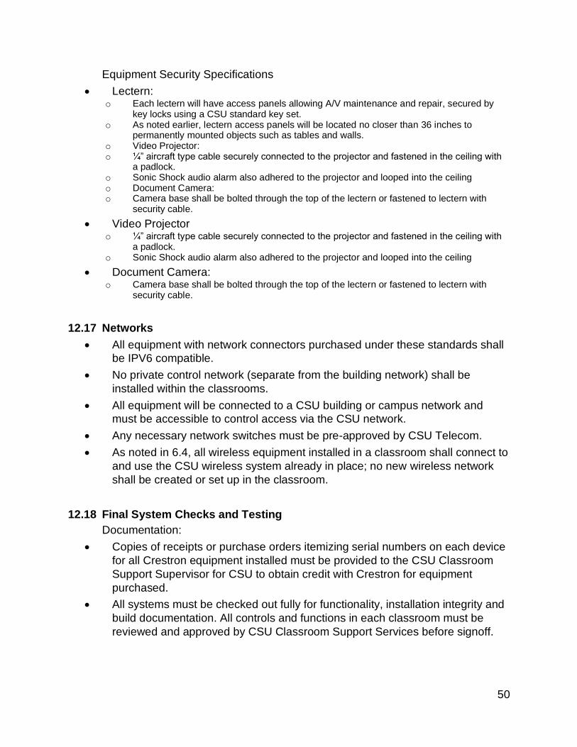
Powers 50
Equipment Security Specifications
• Lectern: o Each lectern will have access panels allowing A/V maintenance and repair, secured by
key locks using a CSU standard key set. o As noted earlier, lectern access panels will be located no closer than 36 inches to
permanently mounted objects such as tables and walls. o Video Projector: o ¼” aircraft type cable securely connected to the projector and fastened in the ceiling with
a padlock. o Sonic Shock audio alarm also adhered to the projector and looped into the ceiling o Document Camera: o Camera base shall be bolted through the top of the lectern or fastened to lectern with
security cable.
• Video Projector o ¼” aircraft type cable securely connected to the projector and fastened in the ceiling with
a padlock. o Sonic Shock audio alarm also adhered to the projector and looped into the ceiling
• Document Camera: o Camera base shall be bolted through the top of the lectern or fastened to lectern with
security cable.
12.17 Networks
• All equipment with network connectors purchased under these standards shall
be IPV6 compatible.
• No private control network (separate from the building network) shall be
installed within the classrooms.
• All equipment will be connected to a CSU building or campus network and
must be accessible to control access via the CSU network.
• Any necessary network switches must be pre-approved by CSU Telecom.
• As noted in 6.4, all wireless equipment installed in a classroom shall connect to
and use the CSU wireless system already in place; no new wireless network
shall be created or set up in the classroom.
12.18 Final System Checks and Testing
Documentation:
• Copies of receipts or purchase orders itemizing serial numbers on each device
for all Crestron equipment installed must be provided to the CSU Classroom
Support Supervisor for CSU to obtain credit with Crestron for equipment
purchased.
• All systems must be checked out fully for functionality, installation integrity and
build documentation. All controls and functions in each classroom must be
reviewed and approved by CSU Classroom Support Services before signoff.
Powers 51
Functionality Tests:
• Touch Panel External Buttons Labeled
• Power On Projector
• Select Laptop - Check Video and Audio
• Select Doc Cam - Test Video and Controls
• Select Video Mute and test
• Audio up / down and mute work properly
• Switcher / Scaler is set to the Projectors’ native resolution
Projector Alignment:
• Screen Functional and properly positioned
• Image Properly fills the screen on all images
• Brightness and Contrast check
• Image Keystone set
• Image is sharp and in Focus
• Fan is set to High Altitude mode
Lectern Tests / Checks:
• Little Light Functionality
• Check A/C Power in Cable Nook
• User Network Cable active at Cable Nook
• Plexi / Lexan or Rack Blanks installed in blank spaces
• Inside the Lectern: wired neatly and clear of extra parts
• Lectern Top Clean and void of leftover parts
• Wires Labeled and Block Diagram provided inside the Lectern
Cable Tests:
• Network cable infrastructure to be tested and documented with results provided
to ACNS/Telecom Project Team Lead (see Table 1)

Powers 52
13 Miscellaneous
13.1 Security and Access to Communication Rooms
• Introduction: Physical keys are restricted to a small set of staff:
ACNS/Telecom, CSUPD and a limited set of Facilities staff. Primary access is
to be via cardkey.
• ACNS/Telecommunications requires that all communication rooms be secured
with the campus cardkey standard.
• Physical cylinders must be the Medeco Q-Series.
• Access via key or cardkey is approved by the Director of ACNS/Telecom
• Access to communication rooms cannot be blocked by gates, doors or fences
not utilizing campus master key system.
13.2 Communication Room Numbering
• Communication Rooms to be numbered starting with a "T".

Powers 53
13.3 Building automation provisioning and permanent network solution:
• New Construction requires testing of Building Automation Systems (BAS), Fire
Alarm Systems, Elevators, etc. To test these a building data network is
required. ACNS/Telecommunications would prefer a permanent network
installed but can install a temporary solution for an additional charge. This
additional charge will need to be worked out with ACNS/Telecommunications in
advance of any installation. To ensure permanent networking can be installed,
the required communications rooms (MDF and IDFs) will need to be completed
three weeks prior to any BAS Testing. If neither of these options are
reasonable, the contractor can have a temporary point to point connection
installed at their expense.:
• For a permanent network to be installed, the MDF and any required IDFs will
need to be completed. Completion is defined as clean, dust free (including
dust from any outside construction taking place), locked and accessible to
ACNS/Telecommunications employees only, with ¾ A/C Plywood installed per
specifications. Further definition requires permanent power to be in place, all
cooling installed and completed, drywall operations complete, cable tray and
conduit work completed and that the room is not being used for storage.
• Temporary network solution: For an additional charge,
ACNS/Telecommunications can install a temporary data network to be used for
testing of building systems. This additional charge includes temporary
switches, cleaning and re-calibrating test equipment, professionally cleaning
the communications rooms prior to installation, cleaning all fiber connections
after the temporary network has been removed and before the permanent
network is installed.
• Please refer to the ACNS/Telecommunications contact from Table 1.
Powers 54
Appendices
Appendix A – Network Switch Protocol Specifications
Spanning-Tree: 802.1W (RSTP)
• Switch is not set as a root switch nor is the default priority reduced
• No loop or BPDU protect settings on feed port to campus switch. Campus switch port should be configured as a regular data port
LLDP
• LLDP supported and enabled SNMP
• SNMP v3 support
• SNMP community changed from the default
• Read/write disabled unless necessary VLANs
• 802.1q support
• No central VLANs are to be configured on exempt switches
• Trunking
• LACP Username/password and switch access
• username/password Changed from the default
• RADIUS authentication support
• SSH support
• https support Multicast/IGMP
• Enabled for all VLANs and port connecting to campus switch Naming/labeling
• Switch description defined in switch configuration including Building name, room number
Routing
• Disabled IPV6
• Supported

Powers 55
Appendix B – Communication Room Layout
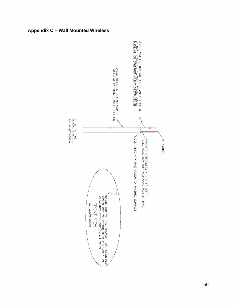
Powers 56
Appendix C – Wall Mounted Wireless

Powers 57
Appendix D – Suspended Ceiling Mounted Wireless

Powers 58
Appendix E – Open Ceiling Mounted Wireless
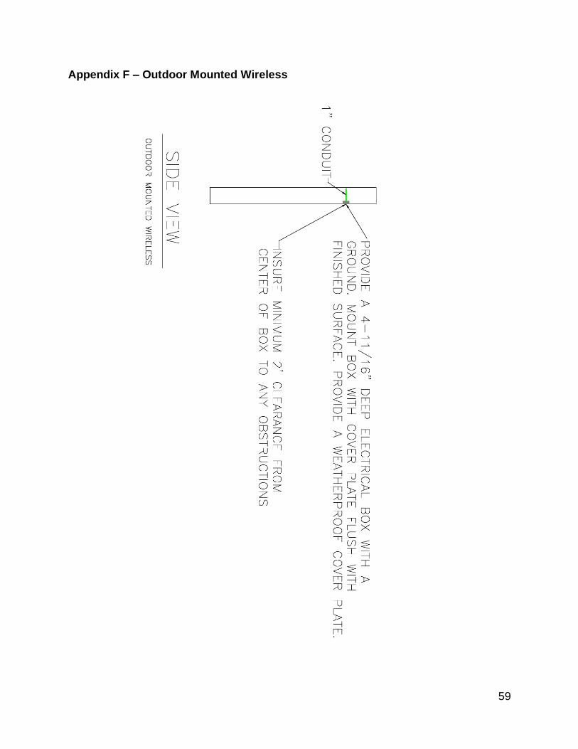
Powers 59
Appendix F – Outdoor Mounted Wireless
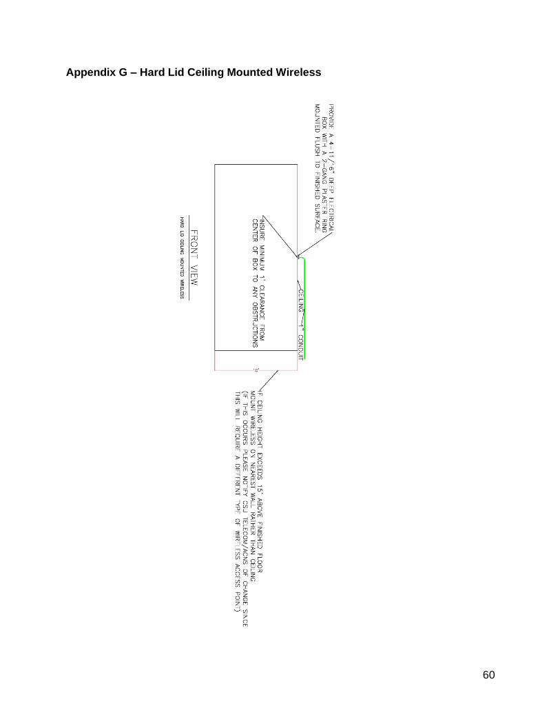
Powers 60
Appendix G – Hard Lid Ceiling Mounted Wireless

Powers 61
Appendix H – Main Building Ground
ANSI/TIA J-STD-607-A
5.3.1

Powers 62
Appendix I - Typical grounding and bounding scheme for a multistory building. (It is intended as a guide rather than explicit instructions.)
ANSI/TIA J-STD-607-A
Figure 3.1-1

Powers 63
Appendix J: Touch screen design samples
Start-up screen:
Operational screen:

Powers 64
Revision History - 22.2 Jan. 1 2020