Embed Size (px)
Citation preview

iASPHALT PAVING DESIGN GUIDE Minnesota Asphalt Pavement Association
AcknowledgementsThis Design Guide was developed in 2002 with the assistance and guidance of a Task Force, which included members from the Minnesota Department of Transportation, the University of Minnesota, the Consulting Engineering Sector, and representatives from MAPA Member Companies.
Numerous resources were used in developing the content of the manual, references to which are made in the reference section but a special thank you is due to the following Organizations for their valuable assistance;
• The Asphalt Pavement Association of Iowa
• The National Asphalt Pavement Association
• The Asphalt Pavement Alliance
• The Asphalt Institute
The Members of the Pavement Design Guidelines Task Force are as follows:
Kent Peterson, Bituminous Roadways, Inc. – Chairman
Blair Bury, Midwest Asphalt Corporation
Chris Duininck, Duininck Brothers, Inc.
Dave Holt, P.E., MAPA
Ann Johnson, P.E., Professional Engineering Services,Ltd.
Dave Johnson, Anderson Bros. Construction Company
Rick Kjonaas, P.E., MnDOT
Dr. Mihai Marasteanu, University of Minnesota
Mike Marti, P.E., SRF Consulting Group, Inc.
John Quade, Bauerly Companies
Dr. Gene Skok, University of Minnesota
Dave Van Deusen, P.E., MnDOT
Richard O. Wolters, P.E., MAPA
In 2014 this design guide was updated.
Jill M. Thomas, P.E. Brandon M. Brever, E.I.T.Executive Director, Associate Director,MAPA MAPA
This document was prepared with the assistance of:

iiASPHALT PAVING DESIGN GUIDE Minnesota Asphalt Pavement Association
Asphalt Paving Design GuidePUBLISHED BY THE MINNESOTA ASPHALT PAVEMENT ASSOCIATIONThe Minnesota Asphalt Pavement Association (MAPA) is an organization of asphalt pavement producers and their associate members. MAPA was formed in 1953 for the purpose of advancing knowledge in the use of this paving material and to provide a service to the public and to the users of asphalt pavement.
The MAPA is constantly seeking new techniques, product improvements, and design methods, all of which are made available for the benefit of pavement users. Design and construction seminars and educational reports and brochures are developed and disseminated to ensure a high-quality product. A wide variety of technical literature and audio-visual presentations are available by contacting MAPA.
Phone: 651-636-4666Fax: 651-636-4790Email: [email protected] Site: www.asphaltisbest.com
The ultimate quality of your asphalt paving project is directly related to the design, materials and experience, skill, and equipment of the involved parties. Behind each contractor is a tremendous investment in equipment, highly skilled personnel, and a pride of workmanship in building asphalt pavements of the highest quality. Whatever the project, MAPA members are your assurance of quality.
MAPA's professional staff and member firms are qualified and eager to serve you. They welcome inquiries about design procedures and cost estimates at any time.
Minnesota Asphalt Pavement Association Suite 100
900 Long Lake Road New Brighton, MN 55112
iiiASPHALT PAVING DESIGN GUIDE Minnesota Asphalt Pavement Association
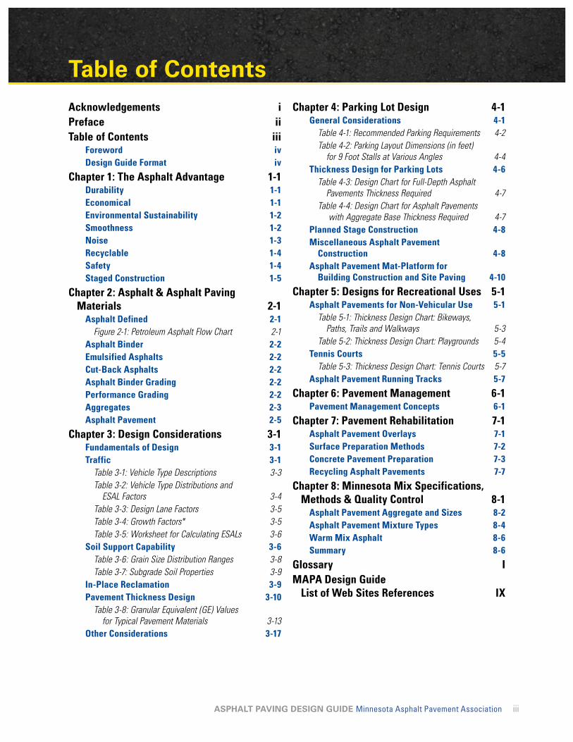
Table of ContentsAcknowledgements iPreface iiTable of Contents iii
Foreword ivDesign Guide Format iv
Chapter 1: The Asphalt Advantage 1-1Durability 1-1Economical 1-1Environmental Sustainability 1-2Smoothness 1-2Noise 1-3Recyclable 1-4Safety 1-4Staged Construction 1-5
Chapter 2: Asphalt & Asphalt Paving Materials 2-1
Asphalt Defined 2-1Figure 2-1: Petroleum Asphalt Flow Chart 2-1
Asphalt Binder 2-2Emulsified Asphalts 2-2Cut-Back Asphalts 2-2Asphalt Binder Grading 2-2Performance Grading 2-2Aggregates 2-3Asphalt Pavement 2-5
Chapter 3: Design Considerations 3-1Fundamentals of Design 3-1Traffic 3-1
Table 3-1: Vehicle Type Descriptions 3-3Table 3-2: Vehicle Type Distributions and
ESAL Factors 3-4Table 3-3: Design Lane Factors 3-5Table 3-4: Growth Factors* 3-5Table 3-5: Worksheet for Calculating ESALs 3-6
Soil Support Capability 3-6Table 3-6: Grain Size Distribution Ranges 3-8Table 3-7: Subgrade Soil Properties 3-9
In-Place Reclamation 3-9Pavement Thickness Design 3-10
Table 3-8: Granular Equivalent (GE) Values for Typical Pavement Materials 3-13
Other Considerations 3-17
Chapter 4: Parking Lot Design 4-1General Considerations 4-1
Table 4-1: Recommended Parking Requirements 4-2Table 4-2: Parking Layout Dimensions (in feet)
for 9 Foot Stalls at Various Angles 4-4Thickness Design for Parking Lots 4-6
Table 4-3: Design Chart for Full-Depth Asphalt Pavements Thickness Required 4-7
Table 4-4: Design Chart for Asphalt Pavements with Aggregate Base Thickness Required 4-7
Planned Stage Construction 4-8Miscellaneous Asphalt Pavement
Construction 4-8Asphalt Pavement Mat-Platform for
Building Construction and Site Paving 4-10
Chapter 5: Designs for Recreational Uses 5-1Asphalt Pavements for Non-Vehicular Use 5-1
Table 5-1: Thickness Design Chart: Bikeways, Paths, Trails and Walkways 5-3
Table 5-2: Thickness Design Chart: Playgrounds 5-4Tennis Courts 5-5
Table 5-3: Thickness Design Chart: Tennis Courts 5-7Asphalt Pavement Running Tracks 5-7
Chapter 6: Pavement Management 6-1Pavement Management Concepts 6-1
Chapter 7: Pavement Rehabilitation 7-1Asphalt Pavement Overlays 7-1Surface Preparation Methods 7-2Concrete Pavement Preparation 7-3Recycling Asphalt Pavements 7-7
Chapter 8: Minnesota Mix Specifications, Methods & Quality Control 8-1
Asphalt Pavement Aggregate and Sizes 8-2Asphalt Pavement Mixture Types 8-4Warm Mix Asphalt 8-6Summary 8-6
Glossary IMAPA Design Guide
List of Web Sites References IX

Acknowledgements
ivASPHALT PAVING DESIGN GUIDE Minnesota Asphalt Pavement Association
FOREWORD This Asphalt Paving Design Guide has been prepared by the members and staff of the Minnesota Asphalt Pavement Association to assist you in understanding asphalt pavement design and construction. It is not intended to take the place of asphalt pavement design done by professional engineers using project specific data. However, it will provide the owner, architect, engineer, developer, and/or government official with basic guidelines to use in the absence of professional services.
Readers are cautioned that the information contained in this Design Guide may be insufficient when used alone, and other resource materials and authorities should be consulted for specific site design.
The criteria for specific pavement design applications are varied. The examples contained in this Design Guide are composites of those designs, procedures, and applications that have proven successful in the state of Minnesota. References to authorities and agencies do not constitute an endorsement by MAPA. Suggested references and authorities should be used by the reader if further clarification is required.
DESIGN GUIDE FORMATThe purpose of this Design Guide is to provide a basic knowledge of asphalt pavement design for the interested layperson. Numerous references have been used and a list of these sources is included in the appendix, directing the reader to further sources of technical information should he or she be interested. Where possible, these references have been linked to websites to provide easy access to additional information. Access to the remaining references can be obtained by contacting the MAPA office.
We at MAPA hope this Design Guide meets its information objective, to provide you, the general reader, with a basic knowledge of asphalt pavement design, the essential properties of asphalt and aggregates, and some of the considerations that engineers need to account for during the pavement design process. We are confident you will find that our MAPA members stand ready to answer any additional questions related to the technical aspects of asphalt pavement you may have after reading this Design Guide.
Chapter 1: The Asphalt Advantage 1-1Durability 1-1Economical 1-1Environmental Sustainability 1-2Smoothness 1-2Noise 1-3Recyclable 1-4Safety 1-4Staged Construction 1-5

1-1ASPHALT PAVING DESIGN GUIDE Minnesota Asphalt Pavement Association
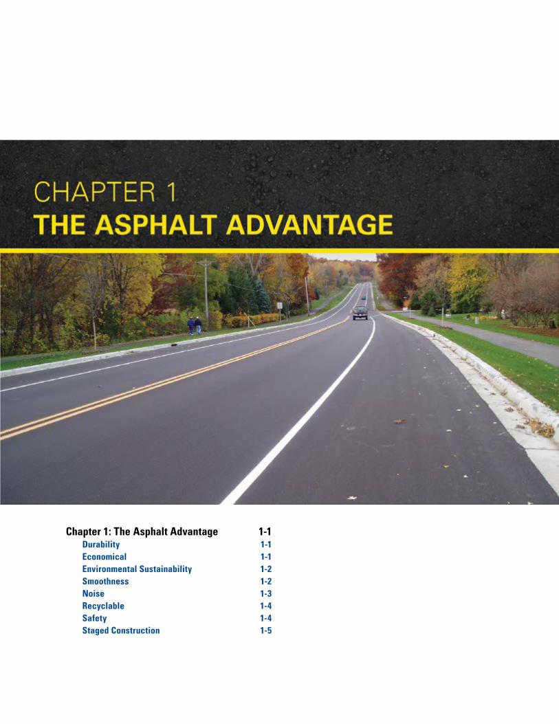
Chapter 1 The Asphalt AdvantageThe use of asphalt pavement provides a fast, efficient and economical construction process with unsurpassed versatility. If rehabilitation is required, it can be accomplished quickly with minimal user delay.
This Design Guide will allow you to choose the pavement materials providing the greatest advantages for every project condition.
DURABILITYAsphalt pavement is a flexible pavement allowing it to withstand occasional over-loads without serious damage. Its resistance to freeze-thaw and deicing salts provides for superior performance during inclement weather. Its lack of repetitive joints removes the possibility of the blowups that plague Portland Cement Concrete during summer heat waves.
ECONOMICALThe Federal Highway Administration has shown that a dollar spent on asphalt pavements goes 26.9 percent further than a dollar spent on concrete pavements. Asphalt is a cost-effective choice because it has a lower first cost than concrete and can be constructed as a “Perpetual Pavement”, resulting in a lower user cost. Staged construction also helps spread out the cost of placement. Because asphalt pavement has no joints to repair and is not affected by freeze-thaw actions, it is much less expensive to maintain.
$-
$0.50
$1.00
$1.50
$2.00
$2.50
$3.00
$3.50
0 10 20 30 40 50Pavement Age (Years)
HMA
PCC
Expe
nditu
res
2001
$
Chapter 1: The Asphalt Advantage
1-2ASPHALT PAVING DESIGN GUIDE Minnesota Asphalt Pavement Association
ENVIRONMENTAL SUSTAINABILITYAsphalt is the sustainable material for constructing pavements. From the production of asphalt pavement to the placement on the road, to rehabilitation, through reuse/recycling, asphalt pavements minimize the impact on the environment. Technologies like recycling asphalt pavement, recycling asphalt shingles, warm mix asphalt, porous pavement and other advances help reduce the life cycle costs and environmental impacts of driving surfaces. Asphalt provides a long-life and smooth pavement for users today and for generations to come.
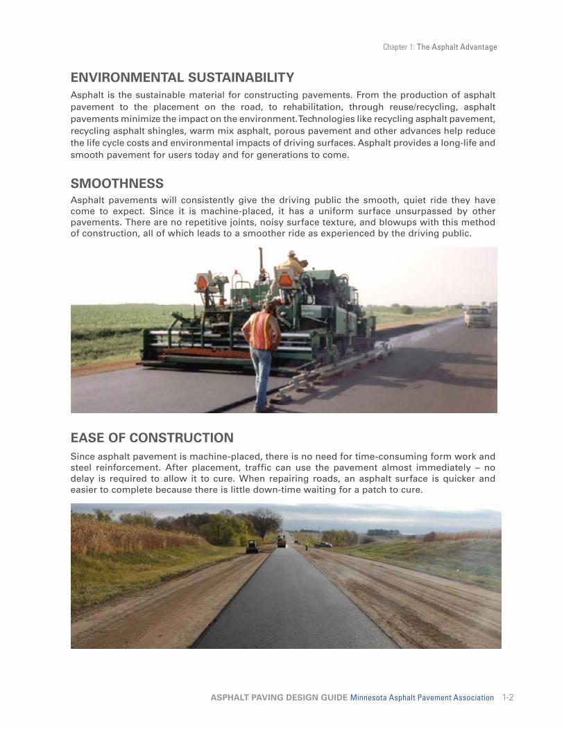
SMOOTHNESSAsphalt pavements will consistently give the driving public the smooth, quiet ride they have come to expect. Since it is machine-placed, it has a uniform surface unsurpassed by other pavements. There are no repetitive joints, noisy surface texture, and blowups with this method of construction, all of which leads to a smoother ride as experienced by the driving public.
EASE OF CONSTRUCTIONSince asphalt pavement is machine-placed, there is no need for time-consuming form work and steel reinforcement. After placement, traffic can use the pavement almost immediately – no delay is required to allow it to cure. When repairing roads, an asphalt surface is quicker and easier to complete because there is little down-time waiting for a patch to cure.

Chapter 1: The Asphalt Advantage
1-3ASPHALT PAVING DESIGN GUIDE Minnesota Asphalt Pavement Association
VERSATILITYThe versatility and popularity of asphalt pavement is evident across the State of Minnesota and the Nation – factories and schools, office parks and playgrounds, and the overwhelming majority of our streets and roads stand as clear testimony that the advantages of asphalt pavement make it America’s first choice for paving and rehabilitation.
NOISEAsphalt pavements are quiet. Data from around the world prove that less traffic noise is generated on asphalt pavement surfaces. Open-graded and Stone Matrix Asphalt (SMA) mixes have been shown to absorb engine and transmission noise.
0
2
4
6
8
10
12
14
16
60 70 80 90 100
Decibels
Noi
se In
tens
ity
The Decibel Scale
Increasing the decibel level by 10 doubles the noise intensity!
Con
vers
atio
n
Trai
n
Cha
in S
aw

Chapter 1: The Asphalt Advantage
1-4ASPHALT PAVING DESIGN GUIDE Minnesota Asphalt Pavement Association
RECYCLABLEAnother major advantage of asphalt pavement is its ability to be completely recycled. Not only can the aggregates be reused, but the asphalt binder also retains its adhesive properties and can be re-used in a new asphalt pavement mix. Pavements are recycled in a conventional asphalt pavement plant with minimal modifications. Recycled pavements have been tested in the laboratory and in the field and have been proven to perform at least as well as virgin aggregate mixes. Over 95 percent of the asphalt pavement plants in Minnesota are capable of using reclaimed asphalt pavement (RAP). Asphalt pavements are 100 percent recyclable; in fact, they are the most recycled product in the United States.
SAFETYAsphalt pavements offer high skid resistance values. The dark color of asphalt reduces glare, helps melt ice and snow, and provides a high contrast for lane markings.
Chapter 1: The Asphalt Advantage
1-5ASPHALT PAVING DESIGN GUIDE Minnesota Asphalt Pavement Association
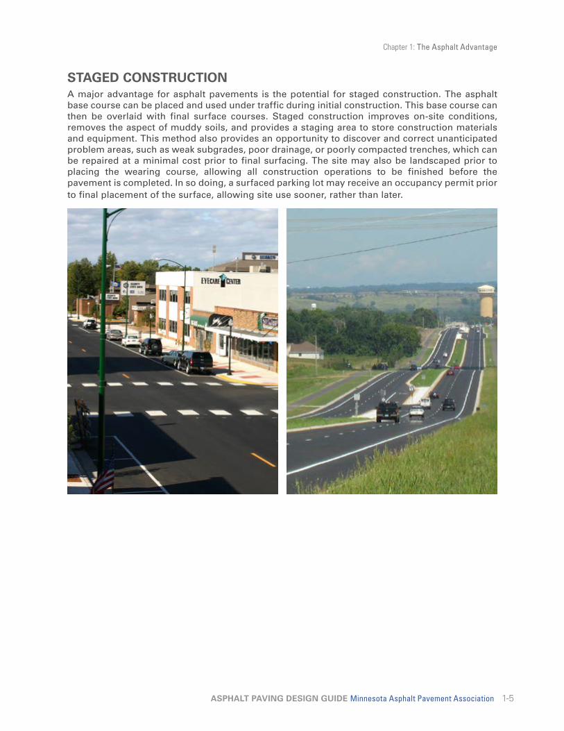
STAGED CONSTRUCTIONA major advantage for asphalt pavements is the potential for staged construction. The asphalt base course can be placed and used under traffic during initial construction. This base course can then be overlaid with final surface courses. Staged construction improves on-site conditions, removes the aspect of muddy soils, and provides a staging area to store construction materials and equipment. This method also provides an opportunity to discover and correct unanticipated problem areas, such as weak subgrades, poor drainage, or poorly compacted trenches, which can be repaired at a minimal cost prior to final surfacing. The site may also be landscaped prior to placing the wearing course, allowing all construction operations to be finished before the pavement is completed. In so doing, a surfaced parking lot may receive an occupancy permit prior to final placement of the surface, allowing site use sooner, rather than later.

Chapter 2: Asphalt & Asphalt Paving Materials 2-1
Asphalt Defined 2-1Figure 2-1: Petroleum Asphalt Flow Chart 2-1
Asphalt Binder 2-2Emulsified Asphalts 2-2Cut-Back Asphalts 2-2Asphalt Binder Grading 2-2Performance Grading 2-2Aggregates 2-3Asphalt Pavement 2-5
2-1ASPHALT PAVING DESIGN GUIDE Minnesota Asphalt Pavement Association
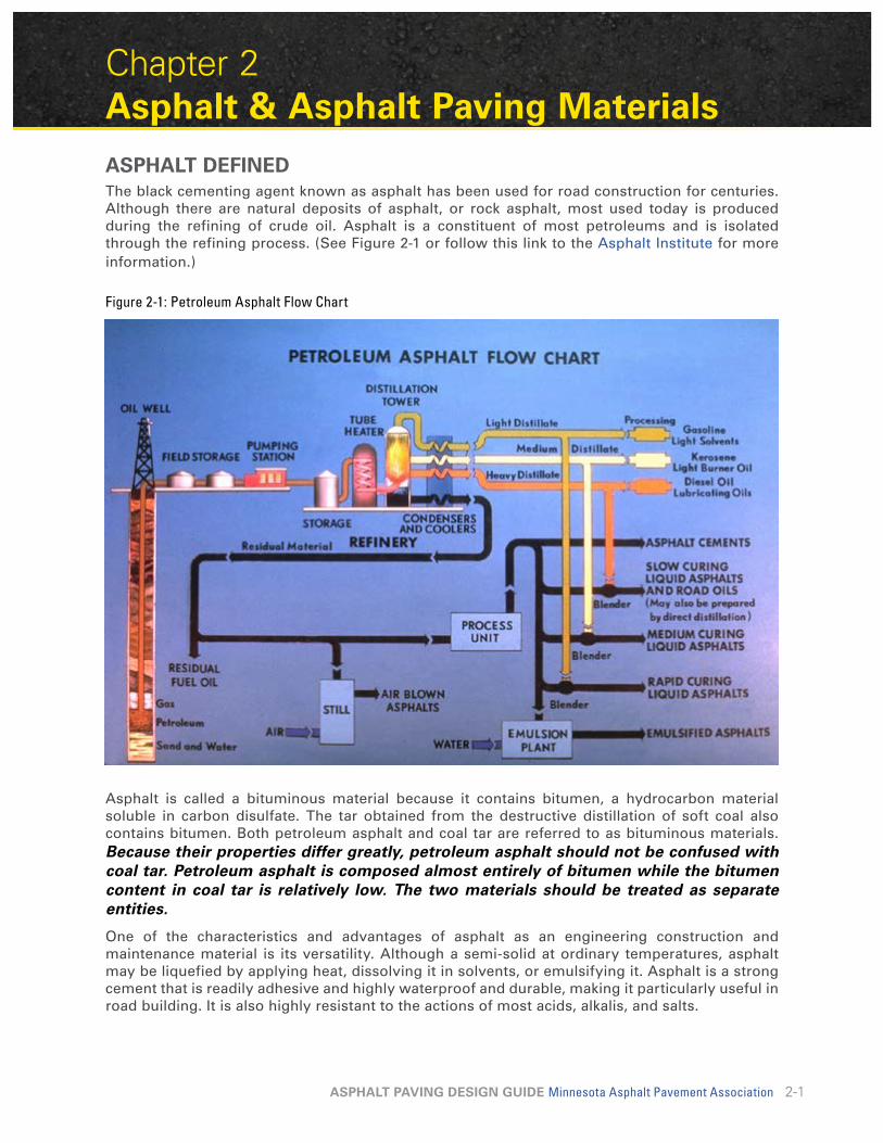
Chapter 2 Asphalt & Asphalt Paving MaterialsASPHALT DEFINEDThe black cementing agent known as asphalt has been used for road construction for centuries. Although there are natural deposits of asphalt, or rock asphalt, most used today is produced during the refining of crude oil. Asphalt is a constituent of most petroleums and is isolated through the refining process. (See Figure 2-1 or follow this link to the Asphalt Institute for more information.)
Figure 2-1: Petroleum Asphalt Flow Chart
Asphalt is called a bituminous material because it contains bitumen, a hydrocarbon material soluble in carbon disulfate. The tar obtained from the destructive distillation of soft coal also contains bitumen. Both petroleum asphalt and coal tar are referred to as bituminous materials. Because their properties differ greatly, petroleum asphalt should not be confused with coal tar. Petroleum asphalt is composed almost entirely of bitumen while the bitumen content in coal tar is relatively low. The two materials should be treated as separate entities.
One of the characteristics and advantages of asphalt as an engineering construction and maintenance material is its versatility. Although a semi-solid at ordinary temperatures, asphalt may be liquefied by applying heat, dissolving it in solvents, or emulsifying it. Asphalt is a strong cement that is readily adhesive and highly waterproof and durable, making it particularly useful in road building. It is also highly resistant to the actions of most acids, alkalis, and salts.

Chapter 2: Asphalt & Asphalt Paving Materials
2-2ASPHALT PAVING DESIGN GUIDE Minnesota Asphalt Pavement Association
ASPHALT BINDERAsphalt is produced in a variety of types and grades ranging from hard-brittle solids to near water-thin liquids. The semi-solid form known as asphalt binder is the basic material used in asphalt pavements. Liquid asphalt is produced when asphalt binder is blended or “cut back” with petroleum distillates or emulsified with water and an emulsifying agent.
At ambient air temperatures, asphalt binder is a black, sticky, highly viscous material. It is a strong and durable binder with excellent adhesive and waterproofing characteristics. Applying heat, which facilitates mixing with mineral aggregates to produce asphalt pavement, can readily liquefy asphalt binders.
The largest use of asphalt binder is for asphalt pavement. After compacting and cooling to air temperature, asphalt pavement is a very strong paving material with the ability to sustain heavy traffic loads while remaining flexible enough to withstand ambient environmental conditions and stresses. Over 96 percent of the hard-surfaced roads in the United States are paved using asphalt pavement.
EMULSIFIED ASPHALTSEmulsified asphalts (also known as emulsions) are low-viscosity mixtures of tiny asphalt binder droplets, water and emulsifying agents. The emulsifying agent coats the surfaces of the asphalt droplets and keeps them suspended in the water prior to application. After application, the asphalt emulsion breaks and the water separates and evaporates. Emulsions are brownish in color during application, but after breaking, the asphalt binder returns to its original black color.
Emulsions are used for a Tack Coat between subsequent layers of asphalt pavement to aid in binding the layers together.
CUT-BACK ASPHALTSCut-back asphalts are low-viscosity liquid asphalt mixtures manufactured by diluting (cutting back) Asphalt Binders with petroleum solvents (cutter stock or diluent). After application, the petroleum solvent evaporates, leaving the asphalt binder residue.
Cut-Back asphalts may be used as a tack coat between subsequent layers of asphalt pavement, particularly when ambient air temperatures are cool.
ASPHALT BINDER GRADINGAsphalt binders appropriate for pavement construction were previously graded based on resistance to penetration and/or viscosity measures. Currently, asphalt binders are graded based on the temperature range over which the binder retains certain desirable characteristics. These desirable characteristics include adequate flexibility to resist cold temperature cracking and sufficient rigidity to resist warm temperature rutting. The current grading system is known as the Performance Grading (PG) system.
PERFORMANCE GRADINGPerformance grading specifications were developed as part of the Strategic Highway Research Program (SHRP) and are a major component of SUPERPAVE. Binders are specified on the basis of the climate and pavement temperatures in which the binder is expected to serve. Performance graded (PG) binders used in Minnesota vary from north to south and with intended use; however, PG 58-28 is the most commonly used grade. The first number (58) represents the average 7-day

Chapter 2: Asphalt & Asphalt Paving Materials
2-3ASPHALT PAVING DESIGN GUIDE Minnesota Asphalt Pavement Association
maximum pavement design temperature in degrees Celsius. This maximum temperature establishes the upper temperature limit for the binder to retain adequate rigidity to resist rutting.
The second number (-28) represents the minimum pavement design temperature in degrees Celsius. The minimum temperature establishes the lower limit for the binder to retain sufficient flexibility to resist thermal cracking.
Physical properties of the binders are measured at various temperatures both before and after laboratory aging. The laboratory aging is conducted to simulate field conditions imposed during the asphalt pavement production process as well as from long-term environmental exposure. Binder physical properties are typically measured using four devices:
• Dynamic Shear Rheometer
• Rotational Viscometer
• Bending Beam Rheometer
• Direct Tension Tester
AGGREGATESAggregates (or mineral aggregates) are hard, inert materials such as sand, gravel, crushed rock, slag, or rock dust. Properly selected and graded aggregates are mixed with the asphalt binder to form asphalt pavements. Aggregates are the principal load-supporting components of an asphalt pavement, totaling approximately 95 percent of the mixture by weight.

Chapter 2: Asphalt & Asphalt Paving Materials
2-4ASPHALT PAVING DESIGN GUIDE Minnesota Asphalt Pavement Association
ClassificationsPaving aggregates are classified according to source or means of preparation. A brief description of the classifications follows:
Pit or Bank-Run AggregatesGravel and sand are pit or bank-run natural aggregates. They are typically screened to proper size before being used for asphalt paving purposes.
Processed AggregatesWhen natural pit or bank-run aggregate has been crushed and screened to make it suitable for asphalt pavements, it is considered a processed aggregate. Crushing typically improves the particle shape by making rounded particles more angular.
Crushed rock is also a processed aggregate. It is created when the fragments of bedrock and large stones are crushed so that all particle faces are fractured. Variation in size of particles is achieved by screening.
In the processing of crushed rock, the fines produced are separated from the other crushed aggregate and may be used as manufactured sand in asphalt pavements.
Synthetic AggregatesAggregates produced by altering both physical and chemical properties of a parent material are called synthetic or artificial aggregates. Some are produced and processed specifically for use as aggregates; others are the byproduct of manufacturing and a final burning process. Blast furnace slag is an example of a synthetic aggregate.
Desirable Properties of AggregatesSelection of an aggregate material for use in an asphalt pavement depends on the availability, cost, and quality of the material, as well as the type of construction for which it is intended. To determine if an aggregate material is suitable for use in asphalt construction, it should be evaluated in terms of the following properties.
1. Size and grading. The maximum size of an aggregate is the smallest sieve through which 100 percent of the material will pass. The Nominal Maximum size is the next sieve larger than the sieve on which 10 percent of the material is retained. How the asphalt pavement mixture is to be used determines not only the appropriate maximum aggregate size, but also the desired gradation (distribution of sizes smaller than the maximum).
2. Cleanliness. An excess of foreign or deleterious substances such as shale, oxides, unsound cherts and/or organic material make some materials unsuitable for paving mixtures.
3. Toughness. Toughness or hardness is the ability of the aggregate to resist crushing or disintegration during mixing, placing, compacting, and other procedures associated with construction or traffic loading.
4. Soundness. Although similar to toughness, soundness is the aggregate’s ability to resist deterioration caused by the weather; for example, the stresses placed on materials during freezing and thawing.
5. Particle shape. The shapes of aggregate particles influence the asphalt mixture’s overall strength and workability as well as the density achieved during compaction. When compacted, irregular particles such as crushed rock tend to “lock” together and resist displacement.

Chapter 2: Asphalt & Asphalt Paving Materials
2-5ASPHALT PAVING DESIGN GUIDE Minnesota Asphalt Pavement Association
6. Absorption. The porosity of an aggregate permits it to absorb asphalt and form a bond between the particle and the asphalt. A degree of porosity is desired, but aggregates that are highly absorbent are generally not used. Absorption is a significant factor in asphalt pavement mix design.
7. Stripping. When the asphalt film separates from the aggregate because of the action of water, it is called stripping. Aggregates coated with too much dust also can cause poor bonding, which results in stripping. Aggregates readily susceptible to stripping action usually are not suitable for asphalt paving mixes unless an anti-stripping agent is used.
The attributes mentioned above are quantitatively measured by standard physical tests and limits are included in standard materials specifications.
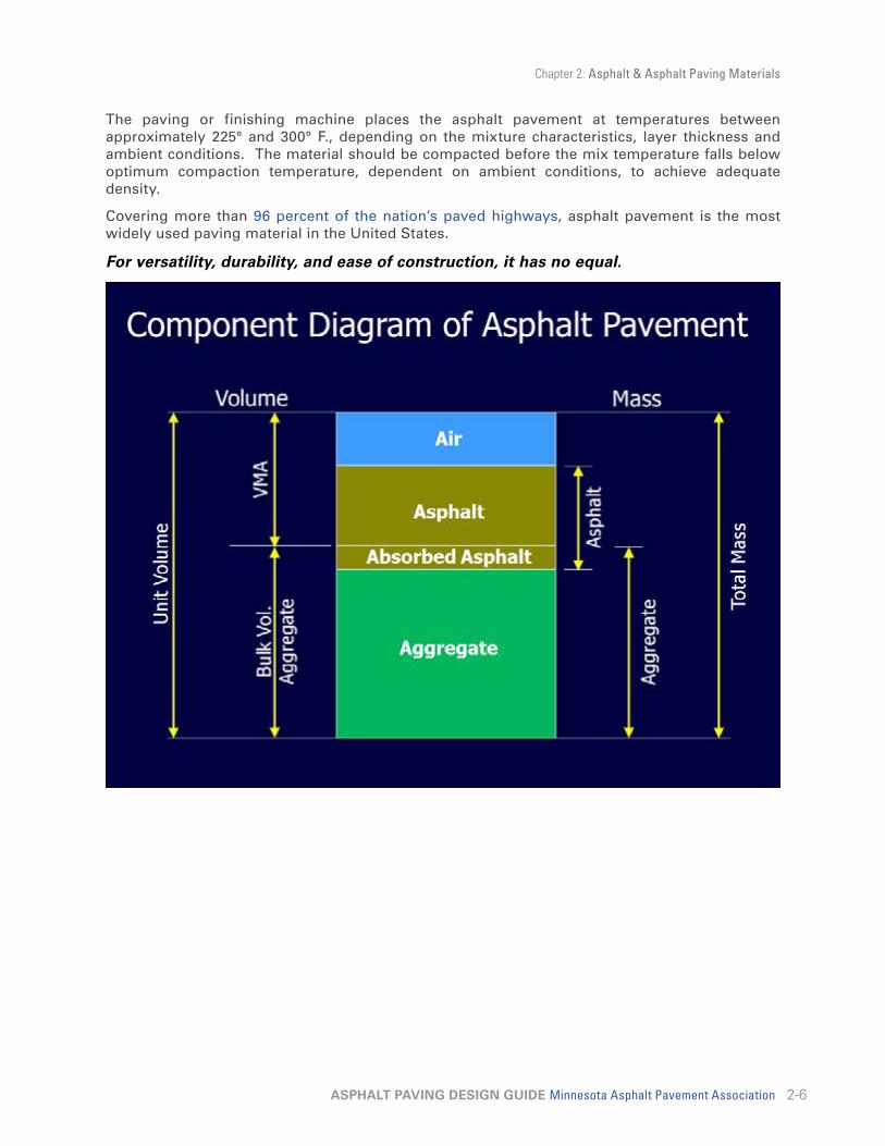
ASPHALT PAVEMENTAsphalt pavement is known by many different names: asphalt pavement, asphaltic concrete, plant mix, bituminous mix, bituminous concrete, hot-mix asphalt, warm-mix asphalt and many others. It is a combination of two primary ingredients - aggregates and asphalt binder. The aggregates total approximately 95 percent of the total mixture by weight. They are mixed with approximately 5 percent asphalt binder to produce asphalt pavement.
The aggregates and asphalt are combined in a manufacturing plant capable of producing specified materials. Plant equipment includes: cold bins for storage and controlled proportioning of graded aggregate; a dryer for drying and heating aggregates to the required mixing temperature; a pug mill or drum for combining the graded, heated aggregate and liquid asphalt cement according to specified mix formulas and tanks for storing the heated liquid asphalt.
Asphalt pavement is transported by truck to the paving site where it is spread to a uniform thickness with a mechanical paving or finishing machine. The material is then compacted to the required degree by heavy, self-propelled rollers, producing a smooth pavement course.
Chapter 2: Asphalt & Asphalt Paving Materials
2-6ASPHALT PAVING DESIGN GUIDE Minnesota Asphalt Pavement Association
The paving or finishing machine places the asphalt pavement at temperatures between approximately 225° and 300° F., depending on the mixture characteristics, layer thickness and ambient conditions. The material should be compacted before the mix temperature falls below optimum compaction temperature, dependent on ambient conditions, to achieve adequate density.
Covering more than 96 percent of the nation’s paved highways, asphalt pavement is the most widely used paving material in the United States.
For versatility, durability, and ease of construction, it has no equal.

Chapter 3: Design Considerations 3-1Fundamentals of Design 3-1Traffic 3-1
Table 3-1: Vehicle Type Descriptions 3-3Table 3-2: Vehicle Type Distributions and
ESAL Factors 3-4Table 3-3: Design Lane Factors 3-5Table 3-4: Growth Factors* 3-5Table 3-5: Worksheet for Calculating ESALs 3-6
Soil Support Capability 3-6Table 3-6: Grain Size Distribution Ranges 3-8Table 3-7: Subgrade Soil Properties 3-9
In-Place Reclamation 3-9
Pavement Thickness Design 3-10Table 3-8: Granular Equivalent (GE) Values
for Typical Pavement Materials 3-13Other Considerations 3-17
3-1ASPHALT PAVING DESIGN GUIDE Minnesota Asphalt Pavement Association
Chapter 3 Design ConsiderationsFUNDAMENTALS OF DESIGNMany types of asphalt pavement structures exist, along with a number of different methods for designing the thickness of each element in any pavement. Fundamental to the design of each project are the following:
1. Traffic loading (volume and type)
2. Soil-support capability (including drainage considerations)
3. Material specifications (aggregate and asphalt), including thickness design
Each element is an important variable in the structural design process. The economic life of the final product depends on the close attention given to detail when analyzing traffic loadings, soil-support capability, and material specifications.
The degree of detail needed in a specific design situation is related to the type of use intended for the pavement and the sensitivity of each variable. For example, a freeway design with large traffic volumes and heavily-loaded trucks requires a careful estimate of traffic; however, for design of a bicycle path, the number of bicycles using the facility is likely not as important a design factor as soil-support capability.
Because drainage and soil-support values are major factors in pavement life, it is important to know the quality of the supporting soil. This is especially true for a facility that will require a large construction investment. An obviously unstable soil condition (noted, perhaps, from previous experiences) will also indicate the need for a soil analysis during the thickness design process of almost any type of pavement.
On the other hand, a specific traffic study or soil analysis for a residential street or parking lot may not be deemed necessary in a certain location. For example, a location having a long and successful record of asphalt pavements constructed for a specific use (e.g., driveways and residential streets) provides the designer with a background for selecting acceptable values in the absence of soil testing and traffic forecasting.
For the users of this Design Guide, much of the design work has been done – design charts are presented for selecting pavement thickness. Traditionally, many designers group pavements according to use and “use tables” are commonly applied throughout the United States. Chapters 4 and 5 provide design tables by specific type of facility use.
TRAFFICThe loading on a pavement is the traffic. The primary function of the pavement is to transmit and distribute the wheel loads to the supporting subgrade. The total effect of the traffic is related to the number and size of the wheel loads. Traffic is composed of axle load applications of various weights and configurations. There are single, tandem and multiple axles with loads ranging from 2,000 pounds up to 50,000 pounds. Tandem and multiple axles can reduce the load effect on a pavement. Therefore, the volume and distribution of vehicle types is very important to estimate the pavement’s anticipated life.
Traffic predictions are based on: (1) historic records of traffic volumes on comparable roads or facilities and, (2) the percentage of trucks.
The first parameter needed to estimate the traffic effect is the total volume in terms of two-way Average Daily Traffic (ADT). ADT can be measured using a pneumatic tube over a number of days or estimated from a traffic map for a similar road. For design purposes the measured values are

Chapter 3: Design Considerations
3-2ASPHALT PAVING DESIGN GUIDE Minnesota Asphalt Pavement Association
converted to Annual Average Daily Traffic (AADT) using daily and seasonal factors specific to Minnesota.
For a roadway in Minnesota the load effects of trucks as a percentage of overall ADT are predicted using either Heavy Commercial Average Daily Traffic (HCADT), or Equivalent Standard Axle Loads (ESALs). HCADT is defined as the number of vehicles with six or more tires predicted on the road 20 years into the future. ESALs are a measure of the accumulation of equivalent 18,000-lb single axles on the design lane over the design life (usually 20 years).
The effects of truck traffic on a pavement can be dramatic. Tests have shown that a single-unit, fully loaded, 80,000-pound truck can cause pavement damage equivalent to that caused by 6,000 automobiles. Careful estimates of expected traffic distribution must therefore be made for proper pavement design.
Determination of Two-Way AADTThe first step for evaluating traffic is to determine the 20-year design AADT for the facility. Average Annual Daily Traffic (AADT) and/or Heavy Commercial Average Daily Traffic (HCADT) may have already been estimated during preliminary design. If not an AADT forecast can be made using the following parameters:
• Inferred growth rate;
• Projected future AADT as a function of population, employment, or other independent variables;
• Least squares projection using historic AADT;
• Analysis of trends and patterns within a travel corridor; or,
• Use of computer-generated, travel demand estimating programs.
Chapter 3: Design Considerations
3-3ASPHALT PAVING DESIGN GUIDE Minnesota Asphalt Pavement Association
Minimum Designs based on AADTIf the design AADT is less than 1500, a minimum design will result when using the MnDOT Soil Factor Design for typical vehicle type distributions.
For the R-Value method minimum designs will result for an AADT less than 1000 for good sandy soils and below 500 AADT for poor silty or clay type soils.
For these minimum designs it will not be necessary to consider vehicle type distributions using HCADT or vehicle type distributions.
These minimum designs are based on the structure necessary to withstand the effects of low applications of the maximum load expected (usually 80,000 lbs. gross load) and Minnesota ambient conditions.
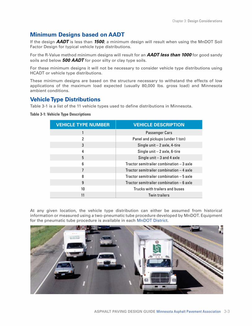
Vehicle Type DistributionsTable 3-1 is a list of the 11 vehicle types used to define distributions in Minnesota.
Table 3-1: Vehicle Type Descriptions
VEHICLE TYPE NUMBER VEHICLE DESCRIPTION
1 Passenger Cars2 Panel and pickups (under 1 ton)3 Single unit – 2 axle, 4-tire4 Single unit – 2 axle, 6-tire5 Single unit – 3 and 4 axle6 Tractor semitrailer combination – 3 axle7 Tractor semitrailer combination – 4 axle8 Tractor semitrailer combination – 5 axle9 Tractor semitrailer combination – 6 axle10 Trucks with trailers and buses11 Twin trailers
At any given location, the vehicle type distribution can either be assumed from historical information or measured using a two-pneumatic tube procedure developed by MnDOT. Equipment for the pneumatic tube procedure is available in each MnDOT District.
Chapter 3: Design Considerations
3-4ASPHALT PAVING DESIGN GUIDE Minnesota Asphalt Pavement Association
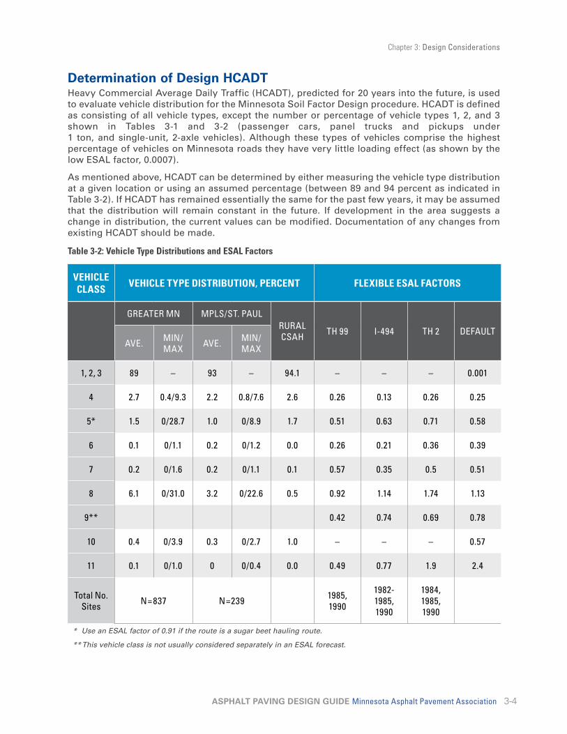
Determination of Design HCADTHeavy Commercial Average Daily Traffic (HCADT), predicted for 20 years into the future, is used to evaluate vehicle distribution for the Minnesota Soil Factor Design procedure. HCADT is defined as consisting of all vehicle types, except the number or percentage of vehicle types 1, 2, and 3 shown in Tables 3-1 and 3-2 (passenger cars, panel trucks and pickups under 1 ton, and single-unit, 2-axle vehicles). Although these types of vehicles comprise the highest percentage of vehicles on Minnesota roads they have very little loading effect (as shown by the low ESAL factor, 0.0007).
As mentioned above, HCADT can be determined by either measuring the vehicle type distribution at a given location or using an assumed percentage (between 89 and 94 percent as indicated in Table 3-2). If HCADT has remained essentially the same for the past few years, it may be assumed that the distribution will remain constant in the future. If development in the area suggests a change in distribution, the current values can be modified. Documentation of any changes from existing HCADT should be made.
Table 3-2: Vehicle Type Distributions and ESAL Factors
VEHICLE CLASS VEHICLE TYPE DISTRIBUTION, PERCENT FLEXIBLE ESAL FACTORS
GREATER MN MPLS/ST. PAULRURAL CSAH TH 99 I-494 TH 2 DEFAULT
AVE. MIN/MAX AVE. MIN/
MAX
1, 2, 3 89 – 93 – 94.1 – – – 0.001
4 2.7 0.4/9.3 2.2 0.8/7.6 2.6 0.26 0.13 0.26 0.25
5* 1.5 0/28.7 1.0 0/8.9 1.7 0.51 0.63 0.71 0.58
6 0.1 0/1.1 0.2 0/1.2 0.0 0.26 0.21 0.36 0.39
7 0.2 0/1.6 0.2 0/1.1 0.1 0.57 0.35 0.5 0.51
8 6.1 0/31.0 3.2 0/22.6 0.5 0.92 1.14 1.74 1.13
9** 0.42 0.74 0.69 0.78
10 0.4 0/3.9 0.3 0/2.7 1.0 – – – 0.57
11 0.1 0/1.0 0 0/0.4 0.0 0.49 0.77 1.9 2.4
Total No. Sites N=837 N=239 1985,
1990
1982-1985, 1990
1984, 1985, 1990
* Use an ESAL factor of 0.91 if the route is a sugar beet hauling route.
** This vehicle class is not usually considered separately in an ESAL forecast.

Chapter 3: Design Considerations
3-5ASPHALT PAVING DESIGN GUIDE Minnesota Asphalt Pavement Association
Determination of Flexible ESAL FactorsAverage ESAL factors represent the average ESAL effect of the 11 vehicle types defined in Table 3-1. The last four columns of Table 3-2 represent ESAL factors calculated from Weigh-In-Motion (WIM) data from around Minnesota. Most WIM sites are located on roadways with 10-ton single-axle load limits with no springtime load restrictions. Table 3-2 is a list of average ESAL factors for each vehicle classification, for the indicated roadways.
Unless detailed axle weight and type, commodity and truck body type, and/or haul direction data are available, the default ESAL factors listed should be used.
Determination of the Design Lane ESAL DistributionTwenty-year accumulation of design ESALs is determined for a critical lane on the given roadway. Table 3-3 is a listing of the conversion factors from two-way traffic to design lane traffic. There may be specific conditions at a given location that dictate using other factors to predict traffic in the design lane.
Table 3-3: Design Lane Factors
NUMBER OF LANES IN TWO DIRECTIONS DESIGN LANE FACTOR
2 0.5
4 0.45
6 0.35
Growth FactorsTable 3-4 is a list of growth factors that can be used for estimating the future cumulative traffic in ESALs. If distribution of vehicle types is expected to change over the design life, growth factors can be applied to individual vehicles such as 5-axle semi-trailers (Type 8).
A growth factor exceeding 4 percent per year is very uncommon, except in areas experiencing significant development. Traffic under these conditions should be predicted with great care.
Table 3-4: Growth Factors*
ANNUAL GROWTH RATE, %DESIGN LIFE, YEARS
10 20
1 10.46 22.02
2 10.95 24.3
3 11.46 26.87
4 12.01 29.78
5 12.58 33.07
*Factor to multiply current annual ESALs by to determine cumulative ESALs over the design life.

Chapter 3: Design Considerations
3-6ASPHALT PAVING DESIGN GUIDE Minnesota Asphalt Pavement Association
State ESAL Traffic Forecast CalculatorTable 3-5 is a sample worksheet that can be used to calculate total ESALs over the design life of the pavement. MnDOT's ESAL traffic forecast calculator is available at http://www.dot.state.mn.us/stateaid/pavement-design.html
Table 3-5: Worksheet for Calculating ESALs
Location: Roadway ________, Limits _________
Current Traffic (AADT): ______________
No. lanes: _________, Design lane factor (Table 3-3) _________
Design Life, years: ______________
Growth Rate: _______________
Growth Factor (Table 3-4): _______________
VEHICLETYPE
% DIST.TABLE 3-2
CURRENTANNUAL NO.
FLEXIBLEESAL FACTOR
CURRENTANNUAL ESALS
CUMULATIVEESALS
1, 2, 3 0.001
4 0.25
5 0.58
6 0.39
7 0.51
8 1.13
9 –
10 0.57
11 2.4
Totals 100 –
SOIL SUPPORT CAPABILITYThe ability of the subgrade to support loads transmitted from the pavement is one of the most important factors in determining pavement thickness. The subgrade must serve as a working platform to support construction equipment and as a foundation for the pavement structure that supports and distributes traffic loads. Thus, it is essential to evaluate the strength of the subgrade before beginning the structural design of the pavement.
If sufficient pavement thickness is not provided, the applied loads could cause greater stresses on the subgrade then it can resist. This may result in deflection of the pavement and ultimately in its failure.
In street and highway construction, the subgrade provides the foundation for the pavement. Different types of soils have different abilities to provide support. A sandy soil, for example, will support greater loads without deformation than a silty clay soil. Thus, for any given traffic volume and weight of vehicles using the roadway, a greater pavement thickness must be provided on clay soils than on sandy soils.

Chapter 3: Design Considerations
3-7ASPHALT PAVING DESIGN GUIDE Minnesota Asphalt Pavement Association
Soil ClassificationsSoil is classified for road and street construction in order to predict subgrade performance on the basis of a few simple tests. The American Association of State and Highway Transportation Officials (AASHTO) classification system for soils is commonly used as a test for subgrade-support value.
According to the AASHTO system, soils that have approximately the same general load-carrying capabilities are grouped in classifications of A-1 through A-7. (See Table 3-7.) In general the best highway subgrade soils are A-1, and the worst are A-7. The classification is based on the sieve analysis, plasticity index, and liquid limit of the soil being tested.
Minnesota has a glacial geology, as shown in Figure 3-1. Local soil types vary significantly, and local conditions can be identified through soil borings and subsurface investigations. Borings should be spaced to adequately assess the underlying soil conditions. These soil surveys help the designer to characterize the underlying soil composition, assumed strength, and water table location, which can be used for design and development of the plans and specifications. Unexpected soil conditions can be costly, and soil surveys and assessment are often well worth the initial investment.
Figure 3-1: Minnesota Glacial Geology
http://www.mngeo.state.mn.us/chouse/geology/statewide.html

Chapter 3: Design Considerations
3-8ASPHALT PAVING DESIGN GUIDE Minnesota Asphalt Pavement Association
Soil TextureThe soil texture refers to the relative size of the mineral particles, and is an important characteristic, as it limits and defines the soil’s uses. Most natural soil types are comprised of a combination of many particle sizes. The distribution of these sizes gives the soil a distinctive appearance, which is called texture, and is the term most often used to identify a soil.
There are three main textural classes: coarse or light grained soils, medium grained, and fine or heavy-textured soils. These may also be characterized as gravels, sands, and silts or clays. Grain size ranges for these soil sizes are shown in Table 3-6 according to the MnDOT Grading and Base Manual.
Table 3-6: Grain Size Distribution Ranges
PARTICLE SIZE DIAMETER [MM]
SIEVE SIZES
PASSING RETAINED
Gravel 75 to 2.0 75 mm (3”) 2 mm (No. 10)
Coarse Sand 2.0 to 0.425 2 mm (No. 10) 425 μm (No. 40)
Fine Sand 0.425 to 0.075 425 μm (No. 40) 75 μm (No. 200)
Silt 0.075 to 0.002Cannot be separated by sieving. Determined by
settling velocity in soil-water suspensionClay Smaller than 0.002
Colloidal Clay Smaller than 0.001
Laboratory Determination of Soil TextureTo separate the soil particles by size, a gradation analysis is performed by running the soil sample through a series of sieves. The portion passing or retained on each sieve is measured, and expressed as a percentage. The percentages of smaller size particles which pass the No. 200 sieve are determined by hydrometer analysis, which determines the soil size based on its settling velocity.
Once the percentage of each particle size in the sample is known, the soil can be assigned a textural classification dependent upon the amounts of sand, clay and silt present. Stone and gravel particles larger than the sand size (No. 10 sieve) do not have much effect on the basic soil classification. Soils containing more than 25 percent gravel particles are generally termed gravelly or stony soils.
Subgrade soil properties based on field methods of identification are given in Table 3-7.

Chapter 3: Design Considerations
3-9ASPHALT PAVING DESIGN GUIDE Minnesota Asphalt Pavement Association
Table 3-7: Subgrade Soil Properties
SOIL PROPERTIES
MNDOT CLASSIFICATION
FIELD IDENTIFICATION
RIBBON LENGTH
(IN.)RATING POSSIBLE
EQUIVALENT CLASSES
MNDOT SOIL
FACTORAASHTO ASTM
UNIFIED CBR R-VALUE
Gravel (G) Stones pass 75 mm sieve, retained on 2 mm 0 Excellent 50-75 A-1 GP-GM - ND
Sand (Sa)Will form a cast when wet.
Crumbles easily, 100% passes 2 mm sieve.
0 Good to Excellent 50-75 A-1, A-3 SP-SM 14.1 ND
Loamy Sand (Lsa) Will stand light jarring. 0 Good to Excellent 50-75 A-2 SM, SC 7.2 60
Sandy Loam (SaL) Slightly plastic
(<10% clay)
Slightly plastic. Sand grains seen and felt. Gritty. 0-0.75 Fair to
Good 120-130 A-2 SM, SC 4.3 40
Sandy Loam (SaL) Plastic (10-20%
clay)
Slightly plastic to plastic. Sand grains seen and felt. Gritty. 0.75-1.5 Fair 120-130 A-4 SM, SC 3.9 22
Loam (L) Somewhat gritty, but smoother than SaL. 0.25-1.5 Fair 120-130 A-4 ML, MH 3.6 20
Silt Loam (SiL)Smooth, slippery or velvety.
Cloddy when dry. Easily pulverized.
0.0-1.5 Poor 120-130 A-4 ML, MH 3.1 25
Sandy Clay Loam (SaCL)
Somewhat gritty. Considerable resistance to
ribboning.1.5-2.5 Fair to
Good 100 A-6 SC, SM 3.8 21
Clay Loam (CL) Smooth, shiny, moderate resistance to ribboning. 1.5-2.5 Fair to
Good 100 A-6 CL 3.4 17
Silty Clay Loam (SiCL)
Dull appearance, slippery. Less resistance to ribboning
than CL. Very plastic but gritty. Long, thin ribbon, 50-70%
sand.
1.5-2.5 Poor 120-130 A-6 ML/CL 3.1 16
Sandy Clay (SaC) Very plastic but gritty. Long, thin ribbon, 50-70% sand. 2.5< Fair 120-130 A-7 SC - ND
Silty Clay (SiC)Buttery, smooth, slippery.
Less resistance to ribboning than CL.
2.5< Poor 120-130 A-7 ML/CL 3.1 ND
Clay (C) Smooth, shiny when smeared, long thin ribbon or thread. 2.5< Fair 120-130 A-7 CL, CH 3.2 14
IN-PLACE RECLAMATIONAccording to the Minnesota Department of Transportation (MnDOT) Pavement Design Manual, reclamation/recycling of existing asphalt pavement includes projects that pulverize the existing asphalt pavement and re-use it as base material for new asphalt pavement. This includes Full-Depth Reclamation (FDR), Stabilized Full-Depth Reclamation (SFDR), and Cold In-Place Recycling (CIR).
For more information and/or assistance on FDR, SFDR or CIR, contact the MnDOT Pavement Preservation - Grading and Base Unit of Materials & Road Research. Their web link is at http://www.dot.state.mn.us/materials/gbacontacts.html
Chapter 3: Design Considerations
3-10ASPHALT PAVING DESIGN GUIDE Minnesota Asphalt Pavement Association
PAVEMENT THICKNESS DESIGNCalculations regarding pavement thickness are critical to a cost-effective project. If pavements are thicker than required, then excess dollars are spent on materials and labor that could be better spent elsewhere. If pavements are too thin to support actual traffic, then pavements fail before their anticipated useful life is over.
Pavement thickness design consists of determining the total thickness of pavement required above the subgrade, as well as the various thicknesses of each of the pavement components for traffic and subgrade conditions. Structural designs are based upon the cumulative damaging effect of traffic over a design period (usually 20 years). Traffic calculations are outlined in a preceding section of this chapter.
Thickness Design and Subgrade Strength Because thickness calculations depend on the strength of the finished subgrade, the soil must be tested to determine this information. Tests are based on bearing capacity related to the moisture and density of the soil. The California Bearing Ratio (CBR) is one of the most widely used methods of designing pavement structure. Once the CBR value is determined, the soil classification can be identified, conversely, when the soil classification is known, a relative CBR value can be identified.
Another soil strength indicator is the R-value, also known as the “resistance value” or stabilometer strength of a soil. A soil’s R-value indicates its resistance to deformation. Typical R-values for a variety of soils are given in Table 3-7.
Soil TestingA qualified laboratory can conduct tests to provide soil classification and subgrade strength information, such as a design R-value. Such testing is necessary to ensure a proper structural design and should be part of all major pavement design projects.
Field Compaction Assessment A simple test is available for determining in-place compaction. The Dynamic Cone Penetrometer (DCP). The DCP is an inexpensive and easily transportable tool that was first used by MnDOT in 1991 on the Minnesota Road Research Project (MnROAD) to determine subgrade and base strengths. Since 1993, the DCP has been used by MnDOT as an acceptance tool for the compaction of subdrain trench backfill material.
The DCP consists of two 16 mm rods coupled at midpoint. The lower rod contains an anvil and a pointed tip, which is driven into the ground by dropping a hammer contained on the upper rod onto the anvil. The underlying soil strength is determined by measuring the penetration of the lower shaft into the soil after each hammer drop. This value is recorded in mm/blow and is known as the depth penetration index (DPI). Stiffer or stronger soils have a lower DPI. The DPI is used to identify pavement layer boundaries, determine material layer strengths, or estimate overall strength of the unbound materials.
Construction operations and pavement performance are directly related to subgrade stability. In most situations, construction-based stability considerations will control performance. The existing subgrade CBR should be at least 6 to minimize rutting damage to the finished grade prior to paving, and provide adequate subgrade support for proper compaction of the aggregate base and overlying pavement layers. Subgrade strength may be determined by conducting DCP tests in the unstable grade area. Soils with CBR values less than 8 need remedial procedures such as subcutting with drying and recompaction, or granular borrow backfilling.
Chapter 3: Design Considerations
3-11ASPHALT PAVING DESIGN GUIDE Minnesota Asphalt Pavement Association
Subgrade ClassesFor the designs recommended in this manual, all soils have been divided into three classes: good (G), moderate (M), and poor (P). Design R-values have been assigned to these different subgrade classes.
GoodGood subgrade soils retain a substantial amount of their load-supporting capacity when wet. Included are the clean sands, sand-gravels, and those free of detrimental amounts of plastic soils. Good subgrade soils are relatively unaffected by moisture or frost and contain less than 15 percent passing a No. 200 sieve. A soil classified as “good” will have an R-value of 50 or higher.
ModerateModerate subgrade soils are those that retain a moderate degree of firmness under adverse moisture conditions. Included are such soils as loams, silty sands, and sand gravels containing moderate amounts of clays and fine silts. A soil classified as “moderate” will have an R-value of 15-50.
PoorPoor subgrade soils are those that become quite soft and plastic when wet. Included are those soils having appreciable amounts of clay and fine silt (50 percent or more). The coarse silts and sandy loams may also exhibit poor bearing properties as the result of frost penetration into the subgrade. This also is true where the water table rises close to the pavement surface. A soil classified as poor will have an R-value less than 15.
Subgrade Stabilization Very poor soils can be stabilized with granular material, a geotextile, or additives such as lime, fly-ash, asphalt cement, Portland cement, and combinations of cement stabilizers to improve subgrade support characteristics. The selection of a stabilizing agent, the amount to use, and the application procedure depend on the soil classification and the subgrade-support value desired. These should be determined through appropriate laboratory testing.
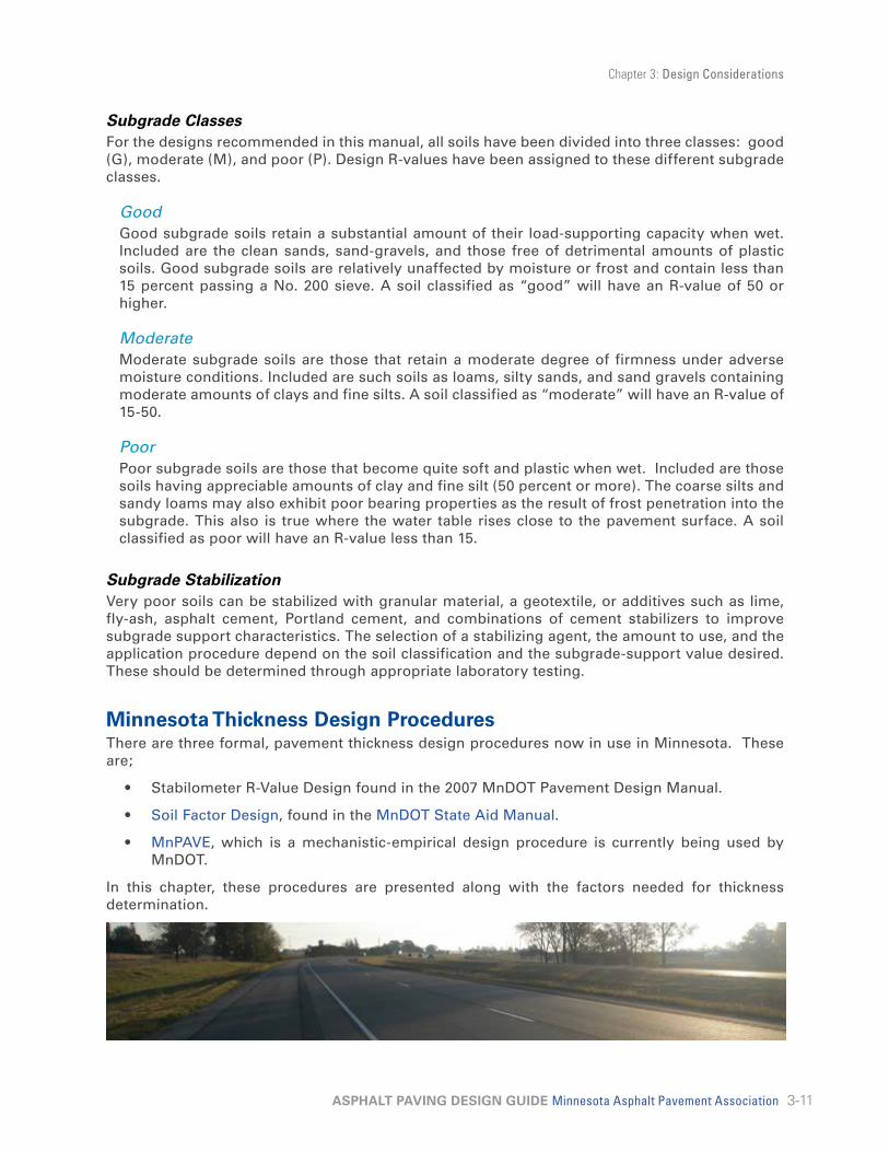
Minnesota Thickness Design ProceduresThere are three formal, pavement thickness design procedures now in use in Minnesota. These are;
• Stabilometer R-Value Design found in the 2007 MnDOT Pavement Design Manual.
• Soil Factor Design, found in the MnDOT State Aid Manual.
• MnPAVE, which is a mechanistic-empirical design procedure is currently being used by MnDOT.
In this chapter, these procedures are presented along with the factors needed for thickness determination.
Chapter 3: Design Considerations
3-12ASPHALT PAVING DESIGN GUIDE Minnesota Asphalt Pavement Association
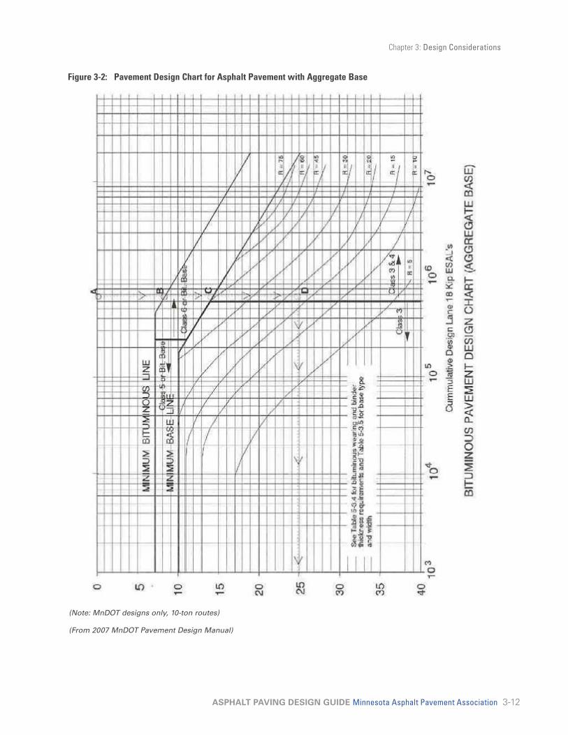
Figure 3-2: Pavement Design Chart for Asphalt Pavement with Aggregate Base
(Note: MnDOT designs only, 10-ton routes)
(From 2007 MnDOT Pavement Design Manual)

Chapter 3: Design Considerations
3-13ASPHALT PAVING DESIGN GUIDE Minnesota Asphalt Pavement Association
Stabilometer R–Value DesignThe design of an asphalt pavement with aggregate base uses the concept of the Granular Equivalent (GE). The granular equivalent thickness of a pavement is determined by assigning granular equivalent values to pavement materials on the basis of their contribution to the pavement strength in comparison to the strength offered by a layer of material classified by the Minnesota Department of Transportation (MnDOT) as Class 5 or 6 aggregate base.
Figure 3-2 is used to determine the total granular equivalent required for the pavement, and a minimum base granular equivalent value.
Figure 3-2 is used to determine the required GE, expressed in inches, for the design-lane cumulative ESALs and subgrade R-values. After the required GE is determined, it is converted into the appropriate asphalt pavement layers and aggregate base thicknesses using the values given in Table 3-8. Once layer thicknesses have been established, total pavement thickness and layer composition is determined.
Table 3-8: Granular Equivalent (GE) Values for Typical Pavement Materials
MATERIAL MNDOT SPECIFICATION GE FACTOR
Asphalt Pavement Surface Course 2.25
Asphalt Pavement Base course 2
Asphalt Treated/Stabilized Base Course 1.5
Aggregate base Class 5, 6 1
Aggregate base Class 3, 4 0.75
Select granular material 0.5
For example, if calculation of traffic and an estimated R-value for an area resulted in a required GE of 16 for a pavement, the designer could develop the following designs:
Design 1
MATERIAL THICKNESS (INCHES) GE FACTOR TOTAL GE
Class 5 aggregate base 8 X 1 = 8
Asphalt Pavement Base Course 2 X 2 = 4
Asphalt Pavement Wear Course 2 X 2.25 = 4.5
Total GE 16.5
Design 2
MATERIAL THICKNESS (INCHES) GE FACTOR TOTAL GE
Class 5 Aggregate Base 6 X 1 = 6
Asphalt Pavement Base Course 3.5 X 2 = 7
Asphalt Pavement Wear Course 1.5 X 2.25 = 3.375
Total GE 16.375

Chapter 3: Design Considerations
3-14ASPHALT PAVING DESIGN GUIDE Minnesota Asphalt Pavement Association
Full Depth Asphalt Pavement Full depth asphalt pavement is defined as a pavement structure in which every layer above the subgrade or improved subgrade is asphalt pavement. Figure 3-3 is used to determine the bituminous pavement thickness for a full-depth asphalt pavement.
Figure 3-3: Pavement Design Chart for Full-Depth™ Asphalt Pavement
Chapter 3: Design Considerations
3-15ASPHALT PAVING DESIGN GUIDE Minnesota Asphalt Pavement Association
Soil Factor DesignSince 1954, some pavements in Minnesota have been designed using a table similar to Figure 3-4 (MnDOT State Aid Manual, 2001). This chart uses seven traffic categories based on 20-year projected two-way AADT and HCADT and eight embankment types using the AASHTO classification system. Thickness in terms of Granular Equivalent (GE) is determined for each level of traffic and soil type. Each design also has a specified maximum spring axle load.
Traffic factors used are Average Annual Daily Traffic (AADT) and Heavy Commercial Average Daily Traffic (HCADT). AADT and HCADT normally used for design are values predicted for 20 years into the future. Local conditions must be considered and the predicted value may either be increased or decreased based on the projected future use of the road.
The strength and stiffness of the soil supporting the pavement are dependent on the density and moisture conditions of the constructed soil. Uniformity is also important to minimize differential movement due to settlement, moisture change, and frost. Good construction specifications and procedures must be followed to attain the strength and stiffness inferred in the given soil factors. The soil factor is based on 1 m (3 ft) of compacted embankment soil.
The Granular Equivalent (GE) concept defines a pavement section by equating the thickness of each aggregate base, sub base, or asphalt pavement layer to an equivalent thickness of granular base material. The equation below is used to calculate the Granular Equivalent. In Minnesota Specification 3138, Class 5 or 6 was assigned a GE of 1.0 and all other materials are referenced to this value. The relevant specifications for the other pavement materials are listed in Figure 3-3. Minimum asphalt pavement thickness and total granular equivalents are also shown for each traffic category.
GE = a1D1 + a2D2 + a3D3 +…
Where: D1 = thickness of Asphalt Pavement, in. (mm)
D2 = thickness of granular base course, in. (mm)
D3 = thickness of granular subbase course, in. (mm)
a1, a2, and a3 = GE Factors listed in Table 3-8.
The required design thickness is listed in two categories (minimum asphalt pavement, GE, and total GE). The maximum granular base thickness can be calculated by subtracting the minimum asphalt pavement GE from the total GE. Alternative design combinations of asphalt pavement and granular materials can be determined using the GE factors.

Chapter 3: Design Considerations
3-16ASPHALT PAVING DESIGN GUIDE Minnesota Asphalt Pavement Association
Figure 3-4: Flexible Pavement DesignFL
EXIB
LE P
AVEM
ENT
DES
IGN
USI
NG
SO
IL F
ACTO
RS1,
5
Req
uire
d G
rave
l Equ
ival
ency
(G.E
. in
inch
es) f
or v
ario
us S
oil F
acto
rs (S
.F.)
For n
ew c
onst
ruct
ion
or re
cons
truct
ion
use
proj
ecte
d AD
T or
HC
AD
T; fo
r rec
ondi
tioni
ng p
roje
cts
use
pres
ent A
DT
or H
CA
DT
7 TO
N :
LESS
TH
AN 4
00 A
DT
9 TO
N :
151
TO 3
00 H
CAD
T
507
7.36
507
1450
20.3
757
9.46
757
17.5
7526
.410
07
11.5
100
721
100
32.5
110
712
.411
07
22.4
110
3512
07
13.2
120
723
.812
037
.413
07
1413
07
25.2
130
39.8
7 TO
N :
400
to 1
000
ADT
9 TO
N :
301
TO 6
00 H
CAD
TG
.E. F
ACTO
RB
itum
inou
s P
avem
ent
2.25
Col
d-In
plac
e R
ecyc
ling
(CIR
)1.
550
796
507
16R
ubbl
ized
Con
cret
e1.
575
712
757
20.5
Full-
Dep
th R
ecla
mat
ion
1.0
100
715
100
725
Sta
biliz
ed F
ull-D
epth
Rec
lam
atio
n1.
511
07
16.2
110
726
.8A
ggre
gate
Bas
e cl
ass
5 &
61.
012
07
17.4
120
728
.6A
ggre
gate
Sub
-Bas
e cl
ass
3 &
40.
7513
07
18.6
130
730
.4Se
lect
Gra
nu
lar M
at’l
0.5
9 TO
N :
LESS
TH
AN 1
50 H
CAD
T9
TON
: 60
1 TO
110
0 H
CAD
TAA
SHTO
SOIL
FAC
TOR
ASSU
MED
GEN
ERAL
4
SOIL
CLA
SS(S
.F.)
R-V
ALU
EPL
ASTI
CIT
YA
- 1
50 -
7570
- 75
N
PA
- 2
50 -
7530
- 70
SP
507
10.3
650
818
.5A
- 3
5070
N
P75
713
.975
823
.7A
- 4
100
- 130
20
SP10
07
17.5
100
829
A-5
130
+na
na
110
719
110
831
.1A
- 6
100
12
P12
07
20.5
120
833
.2A
- 7
- 512
012
P
130
722
130
835
.3A
- 7
- 613
010
P
Val
ues
may
not
be
exac
t due
to ro
undi
ngN
otes
:1 Fo
r 10
Ton
des
ign
see
page
31
in M
nDO
T P
avem
ent M
anua
l, Ju
ly 2
007,
Cha
pter
5, S
ectio
n 3,
Fig
ure
5-3-
7. B
itum
inou
s P
avem
ent D
esig
n C
hart
(Agg
rega
te B
ase)
2 For H
CA
DT
over
150
0 m
ore
adva
nced
des
ign
proc
edur
es s
houl
d be
use
d; p
leas
e co
ntac
t MnD
OT'
s P
avem
ent D
esig
n U
nit
3 See
pag
e 32
in M
nDO
T P
avem
ent M
anua
l, Ju
ly 2
007,
Cha
pter
5, S
ectio
n 3,
Tab
le 5
-3.4
- G
ranu
lar E
quiv
alen
t (G
.E.)
fact
ors
4 Gen
eral
Pla
stic
ity: N
P =
non
plas
tic; S
P=
sem
i-pla
stic
; P =
pla
stic
; na
= no
t app
licab
le (A
n A
-5 s
oil r
arel
y oc
curs
in M
inne
sota
)5 S
afet
y ed
ge (3
0° to
35°
wed
ge) a
re re
com
men
ded
to m
inim
ize
edge
dro
poff.
See
ww
w.d
ot.s
tate
.mn.
us/s
tate
aid/
sa_s
afet
y_ed
ge.h
tml
6 Th
ese
GE
valu
es a
re fo
r the
fini
shed
pav
emen
t sec
tion.
Dur
ing
cons
truct
ion
addi
tiona
l GE
may
be
war
rant
ed fo
r a c
onst
ruct
ion
plat
form
.3138
S.F
.M
inim
um B
it G
.E.
Tota
l
G.E
.
3138
3149
.2B
2
S.F
.M
inim
um
Bit.
G.E
.To
tal
G
.E.
S.F
.M
inim
um B
it.
G.E
.To
tal
G
.E.
S.F
.M
inim
um B
it.
G.E
.To
tal
G
.E.
SPEC
IFIC
ATIO
NTY
PE O
F M
AT'L
3
S.F
.M
inim
um B
it.
G.E
.To
tal
G
.E.
S.F
.M
inim
um B
it.
G.E
.To
tal
G
.E.
S.F
.M
inim
um B
it G
.E.
Tota
l
G.E
.
9 TO
N :1
101
- 150
0 H
CAD
T 2
8 8 8 8 8 8
2360
2331
2231
2331
2331

Chapter 3: Design Considerations
3-17ASPHALT PAVING DESIGN GUIDE Minnesota Asphalt Pavement Association
MnPAVE DesignThe Minnesota Department of Transportation and the University of Minnesota have developed a mechanistic-empirical (M-E) design method for flexible pavements. Because of the great quantity of data and analyses used for design, the procedure has been developed as a software package (MnPAVE). The MNPave software can be downloaded online at http://www.dot.state.mn.us/app/mnpave/index.html
Additional information regarding the MnPAVE program can be found online at www.mnroad.dot.state.mn.us/research/mnroad_project/restools/restools90.asp
Figure 3-5: M-E Design Criteria Overview & Procedure
A. Structural – Thickness Determination
• Fatigue cracking, bottom initiated
• Distortion – Subgrade protection
• Modulus ratio of adjacent unbound layers
• Maximum deflection
B. Functional – Material Properties
• Fatigue cracking, surface initiated
• Rutting, Plastic strain in paving layers
• Thermal Cracking
• Roughness
M-E Design Criteria Overview
M-E Thickness Design Procedure –Criteria:
High Quality Surface Mix
Asphalt Pavement Binder Mix
Asphalt Pavement Base Mix
Aggregate Base, E3={E2’ t3}
Aggregate Subbase E2={E1’ t2}
Subgrade, E1
1. Limit Layer Modulus Ratio of Unbound Materials
2. Subgrade Protection
3. Fatigue of Asphalt Pavement Layers
4. Maximum Surface Deflection
OTHER CONSIDERATIONSDrainageSubsurface water is free water that percolates through, or is contained in, the soil beneath the pavement surface. When it emerges or escapes from the soil, it is referred to as seepage water, and the point of emergence is called a seepage area or a spring. Since the presence of water reduces the strength of the pavement structure, it is important to remove subsurface water from the pavement structure.
Water may rise from the underlying soil through the subgrade and into the pavement structure. This free water could move readily into an aggregate base layer to a low point on the profile. If steep grades are present, and the subsurface water flowing in an aggregate base to the low spot is not intercepted, a hydrostatic head may result, causing pavement distress. Water in the pavement courses also may contribute to the stripping of asphalt films from the aggregate particles.

Chapter 3: Design Considerations
3-18ASPHALT PAVING DESIGN GUIDE Minnesota Asphalt Pavement Association
SubdrainsSubdrains are required when water collects in the pavement structure. Identification of these areas and determination of drain locations requires the technical expertise and insight of an engineer. The choice of drain filter material and the design of the drainage system must be given careful attention by experts. Perforated and slotted pipe can be used to move the free water from the trouble spot to a drainage area.
Subgrade drains should be considered whenever the following conditions exist:
• high groundwater levels, which may reduce subgrade stability and provide a source of water for frost action
• silty or very fine sand subgrade soil, which may become quick or spongy when saturated
• water seeping from underlying water-bearing strata
• cuts in terrain that intercept the natural drainage path of higher elevations
• sag curves with low-permeability subgrade soils
In general, drains should not be located too close to the pavement (to prevent damage to one when working on the other), and some provision should be made to prevent the infiltration of silt and fines into the drain. Geotextile sleeves may be placed around the drains for this purpose.
The Use of Geofabrics in an Asphalt Pavement SectionGeofabrics have been used in asphalt pavement sections for many years primarily as a separation layer between fine-grained subgrade soils and granular subbase or base layers. Geofabric is the most effective solution to use when the soil is at or near saturation and the pumping action of traffic will tend to cause contamination of the granular layer.
A Type V or VI geofabric (defined in MnDOT Specification 3733) should be used. This permeable material allows the passage of water and not soil.
Geofabrics when properly installed will act as good separation layers, but should not be used as a substitute for part of the design thickness of any of the pavement layers.
Check Drainage During ConstructionRegardless of the care used in the preliminary investigation, the soil survey, and the pavement structure design, it is usually impossible to determine from soil borings the exact elevation of water-bearing strata or the rate of flow that will develop. For this reason, a careful designer will reevaluate conditions and check the need for, and adequacy of, subsurface drainage indicated on plans.
Soil conditions should be observed during the grading and subgrade preparation work. Any wet, soft, or spongy areas encountered during grading should be investigated and provisions made for their proper drainage. Even a minor rate of seepage may build up to a large quantity of water over a period of time if the water is not allowed to escape. Soft spots will often cause structural failure soon after traffic is allowed to use the new facility, and must be repaired before paving. After the pavement is in place, any corrective measures needed will be costly, create traffic problems, and cause poor public relations.
Areas of the subgrade that are anticipated for asphalt paving may be tested for uniformity and adequacy of support by driving a loaded dump truck at a speed of 2 to 3 mph over the entire surface. Areas that show a deflection of one or more inches should be further improved with an additional thickness of asphalt pavement. When the improvement is completed, the finished grade should be hard, stable and constructed in reasonably close conformance with the lines, grades and proposed typical cross sections. This will provide a working platform for paving construction

Chapter 3: Design Considerations
3-19ASPHALT PAVING DESIGN GUIDE Minnesota Asphalt Pavement Association
equipment and associated activities. This process can also be used to evaluate the stability of aggregate base; however, the deflection should be minimal.
The image above shows the geofabric acting as a separation layer to restrict soil particles from pumping up to the aggregate layer.
Chapter 4: Parking Lot Design 4-1General Considerations 4-1
Table 4-1: Recommended Parking Requirements 4-2Table 4-2: Parking Layout Dimensions (in feet)
for 9 Foot Stalls at Various Angles 4-4Thickness Design for Parking Lots 4-6
Table 4-3: Design Chart for Full-Depth Asphalt Pavements Thickness Required 4-7
Table 4-4: Design Chart for Asphalt Pavements with Aggregate Base Thickness Required 4-7
Planned Stage Construction 4-8
Miscellaneous Asphalt Pavement Construction 4-8
Asphalt Pavement Mat-Platform for Building Construction and Site Paving 4-10
4-1ASPHALT PAVING DESIGN GUIDE Minnesota Asphalt Pavement Association
Chapter 4 Parking Lot Design
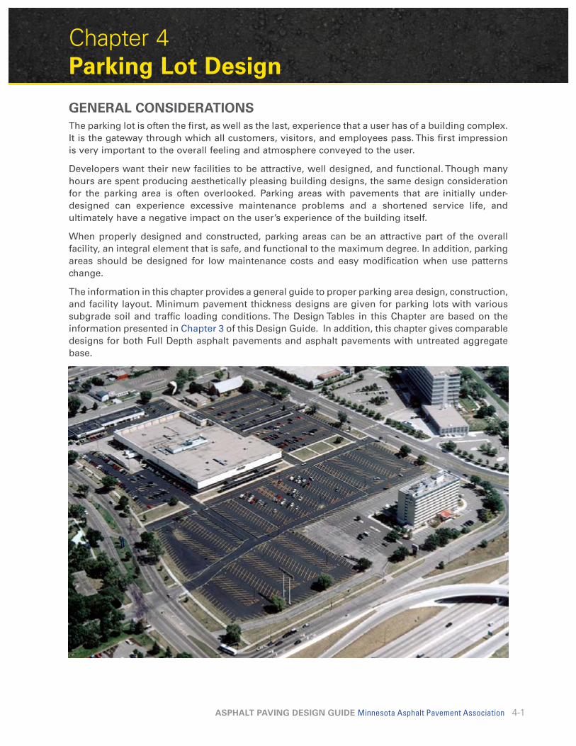
GENERAL CONSIDERATIONSThe parking lot is often the first, as well as the last, experience that a user has of a building complex. It is the gateway through which all customers, visitors, and employees pass. This first impression is very important to the overall feeling and atmosphere conveyed to the user.
Developers want their new facilities to be attractive, well designed, and functional. Though many hours are spent producing aesthetically pleasing building designs, the same design consideration for the parking area is often overlooked. Parking areas with pavements that are initially under-designed can experience excessive maintenance problems and a shortened service life, and ultimately have a negative impact on the user’s experience of the building itself.
When properly designed and constructed, parking areas can be an attractive part of the overall facility, an integral element that is safe, and functional to the maximum degree. In addition, parking areas should be designed for low maintenance costs and easy modification when use patterns change.
The information in this chapter provides a general guide to proper parking area design, construction, and facility layout. Minimum pavement thickness designs are given for parking lots with various subgrade soil and traffic loading conditions. The Design Tables in this Chapter are based on the information presented in Chapter 3 of this Design Guide. In addition, this chapter gives comparable designs for both Full Depth asphalt pavements and asphalt pavements with untreated aggregate base.

Chapter 4: Parking Lot Design
4-2ASPHALT PAVING DESIGN GUIDE Minnesota Asphalt Pavement Association
General PlanningIn developing the parking area plan, several important details should be considered. First and foremost in the mind of the developer may be providing maximum parking capacity while ensuring convenience and safety.
If the locality does not have a zoning ordinance identifying specific requirements for off-street parking, the general recommendations in Table 4-1 may be useful.
(Caution – Check Local Zoning Ordinances before proceeding.)
Table 4-1: Recommended Parking Requirements
LAND USE SPACES/UNIT
Residential
Single-Family 2.0/Dwelling
Multifamily Efficiency 1 -2 Bedroom Larger
1.0/Dwelling1.5/Dwelling2.0/Dwelling
Hospital 1.2/Bed
Auditorium/Theater/Stadium 0.3/Seat
Restaurant 0.3/Seat
Industrial 0.6/Employee
Church 0.3/Seat
College/University 0.5/Student
Retail 4.0/1000 GFA
Office 3.3/1000 GFA
Shopping Center 5.5/1000 GLA
Hotels/Motel 1.0/Room0.5/Employee
Senior High Schools 0.2/Student1.0/Staff
Other Schools 1.0/ClassroomGFA, sq. ft. of gross floor area GLA, sq. ft. of gross leasable area

Chapter 4: Parking Lot Design
4-3ASPHALT PAVING DESIGN GUIDE Minnesota Asphalt Pavement Association
Rules have been developed for optimizing parking area space. Among them are the following:
1. Use rectangular areas where possible.
2. Make the long sides of the parking areas parallel.
3. Design so that parking stalls are located along the lot’s perimeter.
4. Use traffic lanes that serve two rows of stalls.
Special attention should be given to the flow of traffic in and out of the lot as well as circulating routes inside the lot. Keep entrances far away from busy street intersections and from lines of vehicles stopped at a signal or stop sign. Be sure that the entering vehicles can move into the lot on an internal aisle, thereby avoiding congestion caused by involvement with turning vehicles. A pedestrian traffic-flow study is important to provide information about both safety and convenience.
Parking AngleThe most popular angles for parking stalls are 45°, 60°, and 90°. The most common angle for parking is the 60° angle because of the ease of operation it provides. This angle permits reasonable traffic lane widths and eases entry and exit of the parking stall.
Where lot size restricts the dimensions available for aisles and stalls, a 45° angle may be used. The smaller change of direction required to enter and back-out of the stall space permits use of narrower aisles. The 45° angle reduces the total number of parking spaces for a given area but is the only acceptable angle for a herringbone parking lot pattern.
The 90° parking angle provides the most parking spaces for a given area. The high degree of difficulty for entering and leaving these parking stalls makes this type of parking more suited to all-day parking, such as employee parking. This angle is generally not preferred for “in and out” lots such as those of fast food restaurants and banks.
Parking lot angles
Interlock Module

Chapter 4: Parking Lot Design
4-4ASPHALT PAVING DESIGN GUIDE Minnesota Asphalt Pavement Association
Parking Space DimensionsTypical parking stall dimensions vary with the angle at which the stall is arranged in relation to the aisle. Stall widths (measured perpendicular to the vehicle when parked) range from 8 1/2 to 9 1/2 feet. The minimum width for public use parking spaces is 9 feet by 19 feet. Recommended stall dimensions for compacts and similar-sized vehicles are 7 1/2 feet by 15 feet. If a number of such spaces are to be provided, they should be grouped together in a prime area to promote their use. Stall widths for parking lots where shoppers generally have large packages, such as supermarkets and other similar parking facilities, should be 9 1/2 feet or even 10 feet wide.
Table 4-2: Parking Layout Dimensions (in feet) for 9 Foot Stalls at Various Angles
STALL LAYOUT ELEMENTS ON DIAGRAM 45° 60° 75° 90°
Stall width parallel to aisle A 12.7 10.4 9.3 9
Stall length of line B 25 22 20 18.5
Stall depth to wall C 17.5 19 19.5 18.5
Aisle width between stall lines D 12 16 23 26
Stall depth, interlock E 15.3 17.5 18.8 18.5
Module, wall to interlock F 44.8 52.5 61.3 63
Module, interlocking G 42.6 51 61 63
Module, interlock to curb face H 42.8 50.2 58.8 60.5
Bumper overhang (typical) I 2 2.3 2.5 2.5
Offset J 6.3 2.7 0.5 0
Setback K 11 8.3 5 0
Cross aisle, one-way L 14 14 14 14
Cross aisle, two-way M 24 24 24 24
Parking Lot MarkingsMarkings are a very important element of a good parking lot. The parking area should be clearly marked to designate parking spaces and to direct traffic flow. As specified in the Manual on Uniform Traffic Control Devices (MUTCD), parking on public streets should be marked out by using white traffic paint, except for dangerous areas, which should be marked in yellow. Yellow lines are also commonly used in off-street parking lots. All pavement striping should be 4 inches in width.
New asphalt surfaces can be marked with either traffic paint or cold-applied marking tape. For best results with paint application, allow the asphalt pavement to cure for several days.

Chapter 4: Parking Lot Design
4-5ASPHALT PAVING DESIGN GUIDE Minnesota Asphalt Pavement Association
Construction Practices
Drainage ProvisionsDrainage problems are frequently a major cause of parking area pavement failures. It is critical to keep water away from the subgrade soil. If the subgrade becomes saturated, it will lose strength and stability, making the overlying pavement structure susceptible to breakup under imposed loads.
Drainage provisions must be carefully designed and should be installed early in the construction process. Parking area surfaces should have a minimum slope of 2 percent (2’ per 100’). They should be constructed so water does not accumulate at the pavement edge. An underdrain system may be required to carry water away from the pavement structure
If a compacted aggregate base is proposed, place it on the prepared subgrade and compact it to ensure a hard, uniform and stable surface.
The use of asphalt pavement base (compared to use of aggregate base) will greatly reduce the potential for strength and stability problems related to water.
Subgrade PreparationsAll underground utilities should be protected or relocated before grading. All topsoil should be removed. Laboratory tests are recommended to evaluate the load-supporting characteristics of the subgrade soil. However, designs are frequently selected after careful field evaluations based on experience and knowledge of local soil conditions.
The area to be paved should have all debris and vegetation removed. Grading and compaction of the area should be completed so as to eliminate yielding or pumping of the soil.
The subgrade should be compacted to a uniform density of 95 percent of the maximum density. This should be determined in accordance with standard density (Test Method AASHTO T-99). When finished, the graded subgrade should not deviate from the required grade and cross section by more than 1/2 inch in 10 feet.
Areas of the subgrade that are anticipated for asphalt paving may be tested for uniformity and adequacy of support by driving a loaded dump truck at a speed of 2 to 3 mph over the entire surface. Areas that show a deflection of 2 or more inches should be further improved, such as with a compaction subcut or an additional thickness of asphalt pavement. When the improvement is completed, the finished grade should be hard, stable and constructed in reasonably close conformance with the lines, grades and proposed typical cross sections to allow for a working platform for paving construction equipment and associated activities. This process can be used to evaluate the stability of aggregate base, however, the deflection should be minimal.
Asphalt Pavement Surface CourseMaterial for the surface course should be placed in one or more lifts to the true lines and grade as shown on the plans. The asphalt surface should not vary from established grade by more than 1/4 inch in 10 feet when measured in any direction. Any irregularities in the surface of the pavement course should be corrected directly behind the paver. As soon as the material can be compacted without displacement, rolling and compaction should start and should continue until the surface is thoroughly compacted and roller marks disappear.
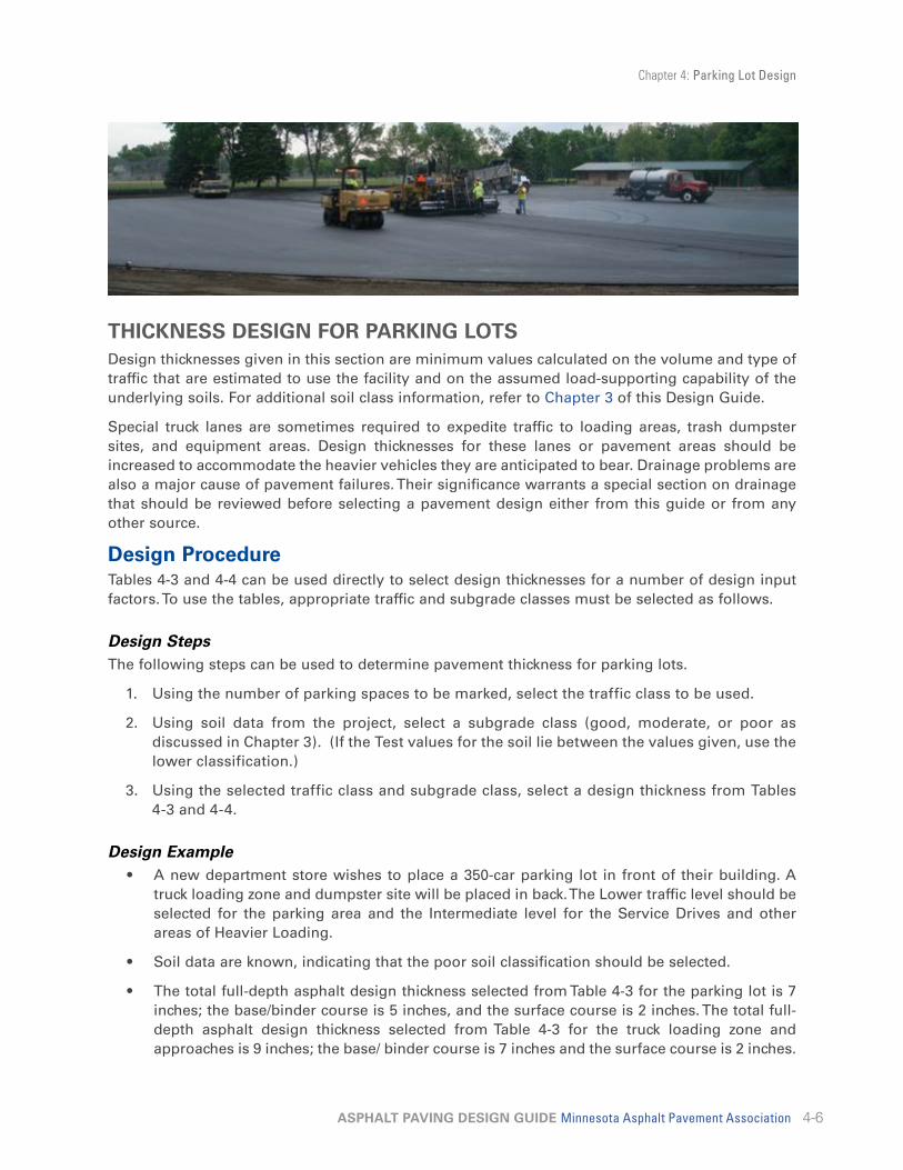
Chapter 4: Parking Lot Design
4-6ASPHALT PAVING DESIGN GUIDE Minnesota Asphalt Pavement Association
THICKNESS DESIGN FOR PARKING LOTSDesign thicknesses given in this section are minimum values calculated on the volume and type of traffic that are estimated to use the facility and on the assumed load-supporting capability of the underlying soils. For additional soil class information, refer to Chapter 3 of this Design Guide.
Special truck lanes are sometimes required to expedite traffic to loading areas, trash dumpster sites, and equipment areas. Design thicknesses for these lanes or pavement areas should be increased to accommodate the heavier vehicles they are anticipated to bear. Drainage problems are also a major cause of pavement failures. Their significance warrants a special section on drainage that should be reviewed before selecting a pavement design either from this guide or from any other source.
Design Procedure Tables 4-3 and 4-4 can be used directly to select design thicknesses for a number of design input factors. To use the tables, appropriate traffic and subgrade classes must be selected as follows.
Design StepsThe following steps can be used to determine pavement thickness for parking lots.
1. Using the number of parking spaces to be marked, select the traffic class to be used.
2. Using soil data from the project, select a subgrade class (good, moderate, or poor as discussed in Chapter 3). (If the Test values for the soil lie between the values given, use the lower classification.)
3. Using the selected traffic class and subgrade class, select a design thickness from Tables 4-3 and 4-4.
Design Example• A new department store wishes to place a 350-car parking lot in front of their building. A
truck loading zone and dumpster site will be placed in back. The Lower traffic level should be selected for the parking area and the Intermediate level for the Service Drives and other areas of Heavier Loading.
• Soil data are known, indicating that the poor soil classification should be selected.
• The total full-depth asphalt design thickness selected from Table 4-3 for the parking lot is 7 inches; the base/binder course is 5 inches, and the surface course is 2 inches. The total full-depth asphalt design thickness selected from Table 4-3 for the truck loading zone and approaches is 9 inches; the base/ binder course is 7 inches and the surface course is 2 inches.

Chapter 4: Parking Lot Design
4-7ASPHALT PAVING DESIGN GUIDE Minnesota Asphalt Pavement Association
Pavement Thickness TablesThe pavement thickness for parking lots should be in accordance with the following tables, which have been developed by MAPA for use when designing small parking lots and driveways. Thicknesses shown were determined using the MnDOT Design procedures after estimates of soil condition and traffic loadings were made. The procedures outlined by MnDOT (as described in Chapter 3) should be used for unusual soil conditions or traffic loadings.
Heavily-Loaded AreasThe pavement for entrances, frontage roads, trash dumpster sites, and delivery truck parking, as well as the approach areas to these spaces, must be increased in thickness to prevent pavement failure caused by the weight and dynamic loading of vehicles. These areas should be constructed with a thickness that will support this special type of loading. Failure to provide this strengthening can result in severe pavement failure.
Table 4-3: Design Chart for Full-Depth Asphalt Pavements (AP) Thickness Required – Inches
SUBGRADE SOIL
TRAFFIC LOADING
CAR LOTS & DRIVEWAYS SMALL TRUCK LOTS (1) LARGE TRUCK LOTS (2)
AP WEAR
AP BASE TOTAL AP
WEARAP
BASE TOTAL AP WEAR
AP BASE TOTAL
GOOD (R>50) 2” 2.5” 4.5” 2” 2.5” 4.5” 2” 4” 6”
MODERATE (R= 15 to 50) 2” 3.5” 5.5” 2” 4” 6” 2” 6” 8”
POOR (R<15) 2” 5” 7” 2” 7” 9” 2” 9” 11”
(1) Less than 100 Trucks per Day. (2) More than 100 Trucks per Day.
Table 4-4: Design Chart for Asphalt Pavements (AP) with Aggregate Base Thickness Required – Inches
SUBGRADE SOIL
TRAFFIC LOADING
CAR LOTS & DRIVEWAYS SMALL TRUCK LOTS (1) LARGE TRUCK LOTS (2)
AP WEAR
AP BIND-
ER/ BASE
AGGRE-GATE BASE
TOTAL GE
AP WEAR
AP BIND-
ER/ BASE
AGGRE-GATE BASE
TOTAL GE
AP WEAR
AP BIND-
ER/BASE
AGGRE-GATE BASE
TOTAL GE
GOOD (R>50) 2” 2 3” 11.5” 2” 2” 4.5” 13” 2” 2” 6” 14.5”
MODERATE (R=15 to 50) 2” 2” 6” 14.5” 2” 2.5” 6” 15.5” 2” 3” 8” 18.5”
POOR (R<15) 2” 3” 6” 16.5” 2” 3” 9” 19.5” 2” 4” 11” 23.5”
(1) Less than 100 Trucks per Day. (2) More than 100 Trucks per Day.
The Design Thickness required for a particular soil type and traffic loading will vary depending on whether Table 4-3 or Table 4-4 is used. Table 4-3 is based on MnDOT’s Full-Depth design, while Table 4-4 is based on MnDOT’s Bituminous Pavement Design Chart (Aggregate Base).

Chapter 4: Parking Lot Design
4-8ASPHALT PAVING DESIGN GUIDE Minnesota Asphalt Pavement Association
PLANNED STAGE CONSTRUCTIONPlanned stage construction is a means of providing fully adequate pavements while effectively using funds, materials, and energy. As defined, it is the construction of an asphalt pavement parking lot or roadway in two or more stages, separated by a predetermined interval of time. In many situations, building pavements in stages makes good economic sense. It is a technique long used by city and county highway engineers.
Stage construction is not maintenance. It is the placement of a minimum depth of pavement during initial construction, and a final surface course placed at a planned future date. Asphalt pavement lends itself to this kind of construction.
Stage construction has the advantage of providing a thoroughly adequate, all-weather pavement for the initial development of an area. Any damage to the Stage 1 pavement caused by traffic, settlement, or utility tearups can be repaired prior to placement of the final surface. With a proper cleaning and an asphalt tack coat, the Stage 2 pavement bonds to the old surface and becomes an integral part of the entire pavement structure.
Caution: A pavement constructed by the stage construction process does not reach full load-carrying capacity until after the final stage has been completed. Because of this fact, isolated areas of distress are possible, which will require repair before the final stage is completed.
MISCELLANEOUS ASPHALT PAVEMENT CONSTRUCTIONAsphalt Pavement GutterAn asphalt pavement gutter has many applications. This is especially true on rural roads that are hilly and in areas where soils are highly erodible. An asphalt pavement gutter offers a method of carrying the water in a manner similar to a curb, yet is much easier to plow in the winter. This is true because rather than a curb rising up to provide a barrier to the plow the gutter profile is below the level of the asphalt pavement.
Asphalt pavement gutters provide a solution to the erosion problem by carrying the water to the bottom of hills and then harmlessly discharging it into a ditch. A spillway must be constructed at the bottom of the hill, or at some predetermined midpoint, to carry the water from the gutter to the bottom of the ditch or pond. While the gutter is not capable of carrying all of the water all of the time (for example, during heavy storms), it does so most of the time, allowing vegetation to be established and eliminating many erosion problems.

Chapter 4: Parking Lot Design
4-9ASPHALT PAVING DESIGN GUIDE Minnesota Asphalt Pavement Association
The asphalt pavement gutter is constructed by first grading the entire roadbed in preparation for the paving. Immediately prior to the actual paving a notch is cut along the proposed edge of the new driving lane. The notch should be at least 2 inches below the surface of the aggregate base of the actual driving lane. The notch can be cut with a motor grader. Excess material generated can be left outside of the outside edge of the new gutter. This material can later be pulled back against the outside of the gutter as backfill. If the gutter is to be backfilled with topsoil, this material must either be left low or wasted on the outer slope. While the typical section shows a round bottom in the notch prior to paving, a square notch will work; however, a square notch will use more asphalt pavement than a round-shaped notch. Typically the equivalent of 3 inches of asphalt pavement should be calculated into the proposed yield for the gutter on a 2 or 2.5 inch surface.
Special care needs to be taken to insure the design of the paver-attached shoe provides the final shape of the gutter since it will not receive any further compaction. The gutter shoe must be attached to the paver on the end of the screed. The shoe should be designed to provide at least a 4-inch screed surface to provide uniformity and compaction. The shoe will need to be heated to provide a tight, smooth surface to the finished gutter.
If the gutter must be crossed to provide access to properties, care must be taken to adequately backfill the gutter with aggregate or, even better, with an apron of asphalt pavement to provide support to the backside of the gutter.
If an existing asphalt pavement roadway has an erosion problem next to the driving surface causing damage to the edge of the pavement, a gutter may be constructed in a similar manner using a shouldering machine rather than a paver. A shoe like that attached to the paver can be constructed and attached to the shouldering machine below the cutting edge of the wing. The preparation work for this type of construction is the same as the procedure for the paver application.
2'
2 MIN DEPRESSION
SCALE = N.T.S.
2" MIN
9" CL. 5 7" CL. 5
1.5'
COMPACTED SUBGRADE
BITUMINOUS GUTTER DETAIL
Chapter 4: Parking Lot Design
4-10ASPHALT PAVING DESIGN GUIDE Minnesota Asphalt Pavement Association
ASPHALT PAVEMENT MAT-PLATFORM FOR BUILDING CONSTRUCTION AND SITE PAVINGSite paving is the recommended first step in many types of building construction projects. It offers several advantages, providing a working mat or platform for shopping centers, schools, manufacturing concerns, warehouses, and similar facilities.
In this technique, an asphalt pavement base course is constructed on a prepared subgrade over the entire area that will become parking areas, service roadways, and buildings. When building construction is completed, a final asphalt pavement surface course is placed on the asphalt pavement base.
AdvantagesPaving a building site before construction is completed has several benefits. These include the following:
1. It ensures constant accessibility and provides a firm platform upon which people and machines can operate efficiently, thereby speeding construction.
2. It provides a dry, mud-free area for construction offices, materials storage, and worker parking, eliminating dust control expenditures.
3. It eliminates the need for costly select material—the asphalt subfloor ensures a floor slab that is dry and waterproof.
4. Steel-erection costs can be reduced because a smooth, unyielding surface results in greater mobility for cranes and hoists.
5. The engineer can set nails in the asphalt pavement as vertical- and horizontal-control points, effectively avoiding the risk of loss or disturbance of this necessary survey work.
6. Excavation for footings and foundations and trenching for grade beams can be accomplished without regard for the asphalt base.
Construction Practices
Subgrade PreparationAll vegetation (including root systems), rocks, debris, and topsoil should be removed from the area being paved, drainage and utility facilities are installed, then backfill and compact. Adjustments in utilities or underground facilities can be readily accomplished through the asphalt base should changes occur.
The subgrade must be properly shaped to meet true lines and elevations. It must be compacted to not less than 95 percent of maximum laboratory density (AASHTO T-99). The surface of the compacted subgrade must not deviate by more than 3/4 inch from the established grade. A minimum slope of about 2 percent (2’ per 100’) should be maintained to provide adequate drainage of surface water from the finished pavement.
Areas of the subgrade that are anticipated for asphalt paving may be tested for uniformity and adequacy of support by driving a loaded dump truck at a speed of 2 to 3 mph over the entire surface. Areas that show a deflection of 2 or more inches should be further improved, such as with a compaction subcut or an additional thickness of asphalt pavement. When the improvement is completed, the finished grade should be hard, stable and constructed in reasonably close conformance with the lines, grades and proposed typical cross sections to allow for a working

Chapter 4: Parking Lot Design
4-11ASPHALT PAVING DESIGN GUIDE Minnesota Asphalt Pavement Association
platform for paving construction equipment and associated activities. This process can be used to evaluate the stability of aggregate base, however, the deflection should be minimal.
Base-Platform Construction
Asphalt pavement base material must be placed on the prepared subgrade. A base of 4 inches or less in depth should be placed in one lift. A base of a total thickness of more than 4 inches may be placed in two or more lifts with the bottom lift being a minimum of 3 inches. The material must be spread and compacted to the required thickness and density as specified and in the grades and dimensions shown on the plans. The surface of the base should not deviate more than 1/2 inch when measured with a 10-foot straight edge.
Surface Course ConstructionAfter building construction is essentially completed, and all building materials and offices have been removed from the previously paved base, preparation for placement of the final surface course of asphalt pavement can begin. Should building operations or winter weather delay placement of the final surface, the asphalt pavement base will adequately serve traffic needs during the interim.
Preparation for the surface course requires thorough cleaning and sometimes washing of the asphalt base to remove tracked-on dirt and foreign particles. After cleaning, any cracked or broken areas in the base should be removed, replaced with asphalt pavement mix, and thoroughly compacted. All manholes, valve boxes, and other pavement fixtures should be brought to finished grade.
The asphalt pavement surface course consists of one or more layers placed on the previously constructed base course. The material must be spread and compacted to the required thickness and in the grades and dimensions shown on the plans. The finished surface should not deviate more than 1/4 inch when measured with a 10-foot straight edge.
Tack CoatA tack or bond coat must be applied at the rate of 0.02 to 0.05 gallons per square yard between each course. The surface must be cleaned of all dust, dirt, or other loose material before the bond coat is applied. If emulsion is used, it should be diluted with equal parts of water or as specified in the proposal.

Chapter 4: Parking Lot Design
4-12ASPHALT PAVING DESIGN GUIDE Minnesota Asphalt Pavement Association
Porous Asphalt Pavement The concept of managing storm water with porous or dense graded asphalt pavement has been done successfully in Minnesota since 2005, and nationally since the 1970’s. The pavement is engineered to allow water to infiltrate on-site and reduce storm water runoff while recharging the groundwater table. Asphalt pavements have been used in various climate conditions with the benefits of providing runoff control, aquifer recharge, reduction of drainage structures needed to comply with storm water regulations, and increased skid resistance and safety. The most common locations for use include parking lots and low volume roads or in high activity recreational areas like basketball and tennis courts or playground lots. Pavement design is also available for heavier load facilities.
As shown in Figure 1, a typical section consists of a porous asphalt pavement layer on top of a choker course layer, a reservoir course (designed for runoff detention frost penetration, and structural capacity), and a non-woven geotextile over the existing soil or subgrade material.
Figure 1 – Managing Storm Water with Asphalt Pavement
Non-Woven Geotextile
Porous Asphalt (Voids > 16%), Thickness Depends on Facility Type
Choker Layer (0.5” Crushed Stone)
Reservoir Layer (Depth as Needed)
(1.5" to 3” Sized Stone)
Typical Porous Asphalt Schematic
The proper design and application of storm water asphalt pavement design is important for successful use of the concept. Soil characteristics, local topography, and climate conditions are physical factors that will be used in the planning and design processes. Other considerations include traffic loading, use of the facility, and agency regulations (i.e. storm water regulations).
Special consideration is needed in the design relative to soil type, topography, and climate conditions. It is recommended that sites with a relatively deep water table be used. Areas with gentle sloping topography are ideal to allow the water to percolate through the system, although terracing the parking lot and using dense-graded asphalt pavement in steeper areas has worked successfully in hilly terrain. Several climate factors should be considered in the design including precipitation rate, depth of frost penetration, and excessive dust in the area. The design should be free of frost susceptible materials (depth as needed).

Chapter 4: Parking Lot Design
4-13ASPHALT PAVING DESIGN GUIDE Minnesota Asphalt Pavement Association
The typical depth of the asphalt pavement layer is 2 to 4-inches, depending upon the facility type. A porous asphalt layer contains little sand or dust, with an air void space of approximately 16 percent or more as compared to dense-graded asphalt pavements designed for two to four percent air voids. Note, a dense graded asphalt pavement could be used rather than porous asphalt layer, however it would require a piping system to distribute water in the reservoir layer. The choker course with ½" sized crushed rock is typically just enough to fill in some voids and lock the surface, thus creating a stable paving platform. The large-stone reservoir layer is the heart of the porous structure and is a crushed stone (between 1.5" and 3" in size) with a depth determined by the storage volume needed, structural capacity, or frost depth, whichever requires the greater thickness. A non-woven geotextile fabric can be placed between the large stone reservoir layer and the subgrade or in-place, uncompacted soil to prevent fines from migrating into the reservoir layer.
Porous asphalt pavements should be inspected several times in the first few months after construction, and annually thereafter. Inspections should be conducted after large storms to check for surface ponding that might indicate possible clogging. The surface can be vacuumed to assist in the maintenance of the pavement surface porosity. A liquid de-icer or fine salt should be used in place of sand, which will clog the system.
A draft guidance document for specifying porous asphalt pavements is available at MAPA's web site. Also, the National Asphalt Pavement Association (NAPA) has guidance on porous asphalt pavements available on their web site.

Chapter 5: Designs for Recreational Uses 5-1Asphalt Pavements for Non-Vehicular Use 5-1
Table 5-1: Thickness Design Chart: Bikeways, Paths, Trails and Walkways 5-3
Table 5-2: Thickness Design Chart: Playgrounds 5-4Tennis Courts 5-5
Table 5-3: Thickness Design Chart: Tennis Courts 5-7Asphalt Pavement Running Tracks 5-7
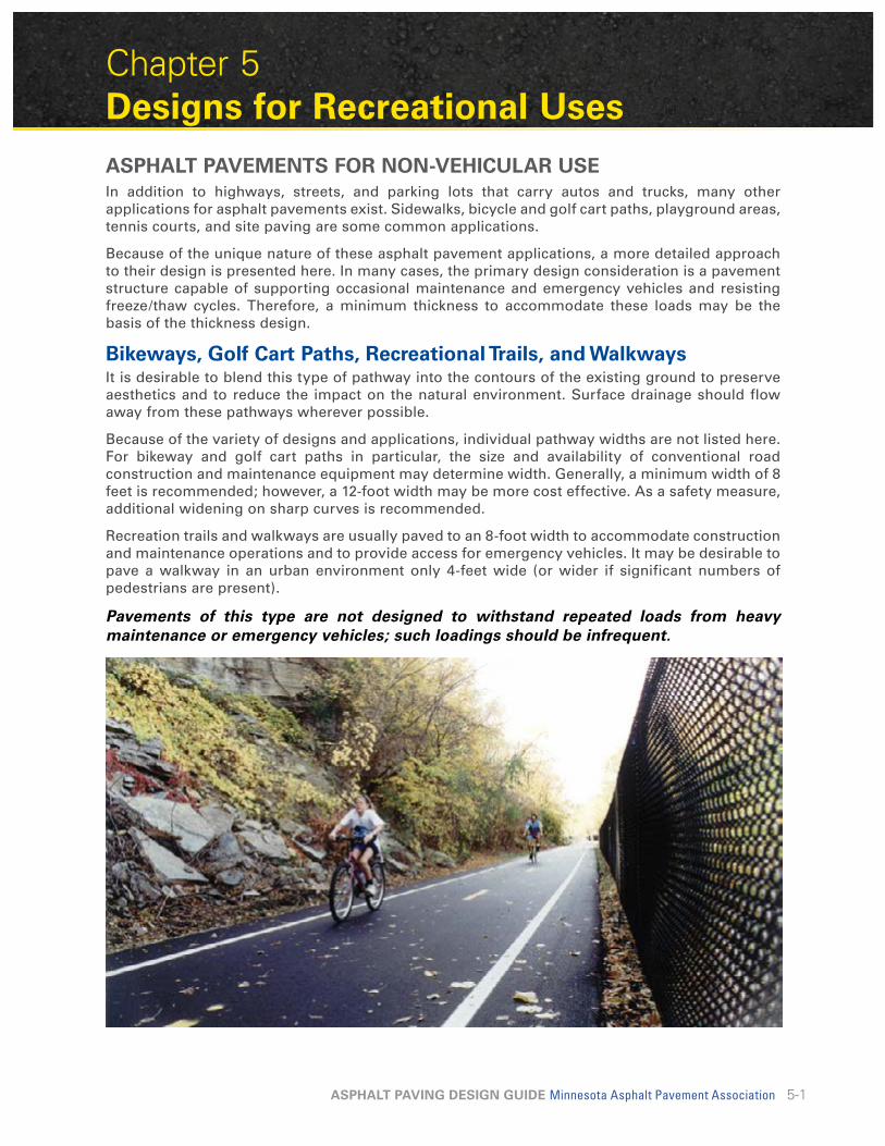
5-1ASPHALT PAVING DESIGN GUIDE Minnesota Asphalt Pavement Association
Chapter 5 Designs for Recreational UsesASPHALT PAVEMENTS FOR NON-VEHICULAR USEIn addition to highways, streets, and parking lots that carry autos and trucks, many other applications for asphalt pavements exist. Sidewalks, bicycle and golf cart paths, playground areas, tennis courts, and site paving are some common applications.
Because of the unique nature of these asphalt pavement applications, a more detailed approach to their design is presented here. In many cases, the primary design consideration is a pavement structure capable of supporting occasional maintenance and emergency vehicles and resisting freeze/thaw cycles. Therefore, a minimum thickness to accommodate these loads may be the basis of the thickness design.
Bikeways, Golf Cart Paths, Recreational Trails, and WalkwaysIt is desirable to blend this type of pathway into the contours of the existing ground to preserve aesthetics and to reduce the impact on the natural environment. Surface drainage should flow away from these pathways wherever possible.
Because of the variety of designs and applications, individual pathway widths are not listed here. For bikeway and golf cart paths in particular, the size and availability of conventional road construction and maintenance equipment may determine width. Generally, a minimum width of 8 feet is recommended; however, a 12-foot width may be more cost effective. As a safety measure, additional widening on sharp curves is recommended.
Recreation trails and walkways are usually paved to an 8-foot width to accommodate construction and maintenance operations and to provide access for emergency vehicles. It may be desirable to pave a walkway in an urban environment only 4-feet wide (or wider if significant numbers of pedestrians are present).
Pavements of this type are not designed to withstand repeated loads from heavy maintenance or emergency vehicles; such loadings should be infrequent.

Chapter 5: Designs for Recreational Uses
5-2ASPHALT PAVING DESIGN GUIDE Minnesota Asphalt Pavement Association
Construction Practices
DrainageIt is very important to keep water away from the subgrade soil. If the soil becomes saturated, it will lose strength and stability, making the overlying pavement structure susceptible to breakup under imposed loads. Both surface and subsurface drainage must be considered. All drainage must be carefully designed and should be installed as early in the construction process as practical.
Bicycle and golf cart paths should have a target slope of 2 percent (2’ per 100’). They should be constructed in such a way that water will not collect at the pavement edge. An underdrain system may be required to carry water away from the pavement structure.
Subgrade PreparationBecause the subgrade must serve both as the working platform to support construction equipment and as the foundation for the pavement structure, it is vital to ensure that the subgrade is properly compacted and graded. All underground utilities should be protected or relocated before grading. All drainage structures should be completed with the grading. Remove all topsoil and debris from the areas to be paved. The subgrade should be shaped properly to meet true alignment and elevation. It should be compacted to not less than 95 percent of maximum laboratory density (AASHTO T-99). The surface elevation should not vary more than 3/4 inch from the established grade.
Areas that show a pronounced deflection under heavy construction traffic indicate instability in the subgrade. Such areas probably require removal of the material and replacement with suitable subgrade soil material such as compacted, crushed stone or compacted, bituminous-concrete base. If a water seepage area is encountered, the subgrade should be drained.
Asphalt PavementsBicycle, golf cart paths, recreational trails, and sidewalks may be constructed in one course or with a separate base and surface course.
When using the full-depth concept, the asphalt pavement base course should be placed directly on the prepared subgrade in one lift, spread and compacted. Compaction is one of the most important construction operations in terms of its contribution to the performance of the completed pavement.
If a compacted aggregate base is proposed, place it on the prepared subgrade and compact it to ensure a hard, uniform and stable surface.
The surface course, or the full-depth asphalt pavement base course, should be placed to the true line and grade. Any irregularities in the surface of this course should be corrected directly behind the paver. As soon as the material can be compacted without displacement, rolling and compaction should be started and should continue until the surface is thoroughly compacted and roller marks have disappeared.
Tack CoatA tack or bond coat must be applied at the rate of 0.02 to 0.05 gallons per square yard between each course. The surface must be cleaned of all dust, dirt, or other loose material before the bond coat is applied. If emulsion is used, it should be diluted with equal parts of water or as specified in the proposal.

Chapter 5: Designs for Recreational Uses
5-3ASPHALT PAVING DESIGN GUIDE Minnesota Asphalt Pavement Association
Pavement ThicknessThe pavement thickness for bikeways, golf cart paths, recreational trails, and walkways should be in accordance with the following table:
Table 5-1: Thickness Design Chart: Bikeways, Paths, Trails and Walkways
SUBGRADE SOIL
FULL-DEPTH ASPHALT PAVEMENT
ASPHALT PAVEMENT- AGGREGATE BASE
ASPHALT PAVEMENT TOTAL ASPHALT
PAVEMENT AGGR BASE TOTAL GE
GOOD (R > 50) 3” 3” 2.5” 4” 9.5”
MODERATE (R = 15 TO 50) 3.5” 3.5” 3.0” 4” 10.75”
POOR (R < 15) 4.5” 4.5” 3.0” 6” 12.75”
Construction Practices
DrainageBoth surface and subsurface drainage should be investigated. If excessive moisture is allowed to accumulate under the pavement, the life of the playground surface may be shortened. If necessary, a system of subsurface drainage must be constructed. Surface drainage on the playground should be directed to the pavement edges and carried away in suitable channels or drainage facilities. It is recommended that the minimum pavement cross-slope be 2 percent (2’ per 100’) to preclude standing water and ensure rapid drainage.
Subgrade PreparationBecause the subgrade must serve as both the working platform to support construction equipment and as the foundation for the pavement structure, it is critical that the subgrade be properly graded and compacted. All drainage structures should be installed with the grading.
Remove all topsoil and debris from the areas to be paved. The subgrade should be properly shaped to meet true alignment and elevation. It should be compacted to not less than

Chapter 5: Designs for Recreational Uses
5-4ASPHALT PAVING DESIGN GUIDE Minnesota Asphalt Pavement Association
95 percent of maximum laboratory density (AASHTO T-99). The surface should not vary more than 3/4 inch from the established grade. Caution should be exercised in the soil selection for the upper portion of the subgrade. A variation in soil type and/or properties can result in differential heave caused by moisture fluctuations and/or frost action that could affect the uniformity of the pavement surface over time.
Areas of the subgrade that are anticipated for asphalt paving may be tested for uniformity and adequacy of support by driving a loaded dump truck at a speed of 2 to 3 mph over the entire surface. Areas that show a deflection of 2 or more inches should be further improved, such as with a compaction subcut or an additional thickness of asphalt pavement. When the improvement is completed, the finished grade should be hard, stable and constructed in reasonably close conformance with the lines, grades and proposed typical cross sections to allow for a working platform for paving construction equipment and associated activities. This process can be used to evaluate the stability of aggregate base, however, the deflection should be minimal.
Base ConstructionIf the full-depth concept of construction is being used, the asphalt pavement base material should be placed directly on the prepared subgrade. The material must be spread and compacted to the required thickness and density as specified and to the grades and dimensions shown on the plans.
If a compacted aggregate base is proposed, place it on the prepared subgrade and compact it to ensure a hard, uniform and stable surface. The surface of the completed base should not deviate more than 1/2 inch when measured with a 10-foot straight edge.
Tack CoatA tack or bond coat must be applied at the rate of 0.02 to 0.05 gallons per square yard between each asphalt pavement course. The surface must be cleaned of all dust, dirt, or other loose material before the bond coat is applied. If emulsion is used, it should be diluted with equal parts of water or as specified in the proposal.
Surface Course ConstructionA surface course of asphalt pavement may be placed on the previously constructed asphalt pavement base after the tack coat has been applied. It must be spread and compacted to the required thickness and density as specified and in the grades and dimensions shown on the plans. The finished surface must not deviate more than 1/4 inch when measured with a 10-foot straight edge.
Pavement ThicknessThe pavement thickness for playgrounds should be in accordance with the following table:
Table 5-2: Thickness Design Chart: Playgrounds
SUBGRADE SOIL
FULL-DEPTH ASPHALT PAVEMENT
ASPHALT PAVEMENT- AGGREGATE BASE
ASPHALT PAVEMENT
ASPHALT PAVEMENT SURFACE
TOTAL ASPHALT PAVEMENT
AGGR BASE TOTAL GE
GOOD (R > 50) 3” 1” 4” 2.5” 4” 9.5”
MODERATE (R = 15 TO 50) 3.5” 1” 4.5” 3.0” 4” 10.75”
POOR (R<15) 4.5” 1” 5.5” 3.0” 6” 12.75”

Chapter 5: Designs for Recreational Uses
5-5ASPHALT PAVING DESIGN GUIDE Minnesota Asphalt Pavement Association
TENNIS COURTSThe following information and design guidance cover the basic components of building durable, economical asphalt pavements for tennis courts. For general guidelines covering layout and dimensions, contact the United States Tennis Association www.usta.com or the United States Tennis & Track Builders Association www.ustctba.com.
These pavements usually are not designed to withstand repeated loads from heavy maintenance or emergency vehicles, but an occasional load application can be made without damage.
Construction Practices
Drainage and Surface SlopeBoth surface and subsurface drainage must be thoroughly investigated. Proper drainage is vital to ensure a non-cracked, smooth playing surface for many years. If subsurface drainage conditions are not satisfactory, a perimeter drain is recommended. An asphalt pavement base on a suitable type of subgrade soil may not require underdrainage.
In order to drain properly, the finished court surfaces should have a minimum slope of 1 inch per 10 feet on a true plane from side to side, end to end, or corner to corner. The surface should not slope away in two directions from the net.
Subgrade PreparationAll topsoil and debris must be removed from the areas to be paved. The subgrade should be properly shaped to meet true alignment and elevation.
The subgrade must be shaped to meet true lines and elevations and compacted to not less than 95 percent of maximum laboratory density (AASHTO T-99). The surface of the compacted subgrade must not vary more than 3/4 inch from the established grade. Good compaction and subgrade soil selection is particularly important in tennis court construction, because differential settlement or heaving from frost action may cause cracking in the court surface. In some cases this can render the court unusable.

Chapter 5: Designs for Recreational Uses
5-6ASPHALT PAVING DESIGN GUIDE Minnesota Asphalt Pavement Association
Base ConstructionIf the full-depth concept of construction is being used, the asphalt pavement base material should be placed directly on the prepared subgrade. The material must be spread and compacted to the required thickness and density as specified and to the grades and dimensions shown on the plans.
If a compacted aggregate base is proposed, it should be placed on the prepared subgrade and compacted to ensure a hard, uniform and stable surface.
The surface of the completed base must not deviate more than 3/8 inch when measured with a 10-foot straight edge but should slope 1 inch per each 10 feet on a true plane from side to side, end to end, or corner to corner as indicated on the plans.
Tack CoatA tack or bond coat must be applied at the rate of 0.02 to 0.05 gallons per square yard between each course. The surface must be cleaned of all dust, dirt, or other loose material before the bond coat is applied. If emulsion is used, it should be diluted with equal parts of water or as specified in the proposal.
Surface Course ConstructionA surface course of asphalt pavement must be placed on the previously constructed asphalt pavement base, spread and compacted to the required thickness and density as specified and to the grades and dimensions shown in the plans.
The finished surface shall not deviate more than 1/8 inch when measured with a 10-foot straight edge but must slope 1 inch per each 10 feet on a true plane from side to side, end to end, or corner to corner as indicated on the plans.
Pavements of this type are not designed to withstand repeated loads from heavy maintenance or emergency vehicles; such loadings should be infrequent.
Caution: Aggregate containing spall and iron-oxides can cause surface pitting and/or staining.
Color Finish Course (If Specified)Before applying the color finish course, the court should be given a water check to determine if there are any depressions (birdbaths) that allow water to pond. This is done by flooding the surface with water and allowing it to drain. Depressions of sizable dimensions – greater than 1/8 inch in depth – should be patched and leveled with the material recommended by the color finish manufacturer.
The color finish material may be one of several proprietary products and must be applied according to manufacturer’s directions.
Playing LinesFollowing construction, it is recommended that a minimum of 15 days elapse before applying the playing lines. A latex striping-paint should be used. It should be placed no thicker than necessary for delineation. Base lines should not be more than 4 inches wide, and playing lines should not be more than 2 inches wide. Base and playing lines must be accurately located and marked in accordance with the rules of the United States Lawn Tennis Association.
If a color finish has been applied, the striping paint should be from a manufacturer and of a type recommended by the surface coating manufacturer. It should be painted in accordance with the paint manufacturer’s standard specifications.
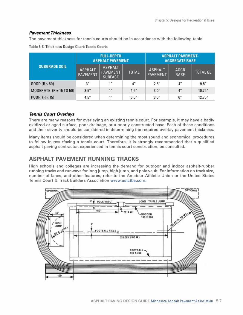
Chapter 5: Designs for Recreational Uses
5-7ASPHALT PAVING DESIGN GUIDE Minnesota Asphalt Pavement Association
Pavement Thickness The pavement thickness for tennis courts should be in accordance with the following table:
Table 5-3: Thickness Design Chart: Tennis Courts
SUBGRADE SOIL
FULL-DEPTH ASPHALT PAVEMENT
ASPHALT PAVEMENT- AGGREGATE BASE
ASPHALT PAVEMENT
ASPHALT PAVEMENT SURFACE
TOTAL ASPHALT PAVEMENT
AGGR BASE TOTAL GE
GOOD (R > 50) 3” 1” 4” 2.5” 4” 9.5”
MODERATE (R = 15 TO 50) 3.5” 1” 4.5” 3.0” 4” 10.75”
POOR (R < 15) 4.5” 1” 5.5” 3.0” 6” 12.75”
Tennis Court OverlaysThere are many reasons for overlaying an existing tennis court. For example, it may have a badly oxidized or aged surface, poor drainage, or a poorly constructed base. Each of these conditions and their severity should be considered in determining the required overlay pavement thickness.
Many items should be considered when determining the most sound and economical procedures to follow in resurfacing a tennis court. Therefore, it is strongly recommended that a qualified asphalt paving contractor, experienced in tennis court construction, be consulted.
ASPHALT PAVEMENT RUNNING TRACKSHigh schools and colleges are increasing the demand for outdoor and indoor asphalt-rubber running tracks and runways for long jump, high jump, and pole vault. For information on track size, number of lanes, and other features, refer to the Amateur Athletic Union or the United States Tennis Court & Track Builders Association www.ustctba.com.
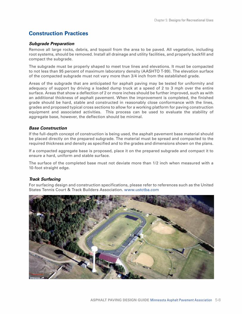
Chapter 5: Designs for Recreational Uses
5-8ASPHALT PAVING DESIGN GUIDE Minnesota Asphalt Pavement Association
Construction Practices
Subgrade PreparationRemove all large rocks, debris, and topsoil from the area to be paved. All vegetation, including root systems, should be removed. Install all drainage and utility facilities, and properly backfill and compact the subgrade.
The subgrade must be properly shaped to meet true lines and elevations. It must be compacted to not less than 95 percent of maximum laboratory density (AASHTO T-99). The elevation surface of the compacted subgrade must not vary more than 3/4 inch from the established grade.
Areas of the subgrade that are anticipated for asphalt paving may be tested for uniformity and adequacy of support by driving a loaded dump truck at a speed of 2 to 3 mph over the entire surface. Areas that show a deflection of 2 or more inches should be further improved, such as with an additional thickness of asphalt pavement. When the improvement is completed, the finished grade should be hard, stable and constructed in reasonably close conformance with the lines, grades and proposed typical cross sections to allow for a working platform for paving construction equipment and associated activities. This process can be used to evaluate the stability of aggregate base, however, the deflection should be minimal.
Base ConstructionIf the full-depth concept of construction is being used, the asphalt pavement base material should be placed directly on the prepared subgrade. The material must be spread and compacted to the required thickness and density as specified and to the grades and dimensions shown on the plans.
If a compacted aggregate base is proposed, place it on the prepared subgrade and compact it to ensure a hard, uniform and stable surface.
The surface of the completed base must not deviate more than 1/2 inch when measured with a 10-foot straight edge.
Track SurfacingFor surfacing design and construction specifications, please refer to references such as the United States Tennis Court & Track Builders Association. www.ustctba.com

Chapter 6: Pavement Management 6-1Pavement Management Concepts 6-1

6-1ASPHALT PAVING DESIGN GUIDE Minnesota Asphalt Pavement Association
Chapter 6 Pavement ManagementPAVEMENT MANAGEMENT CONCEPTSHistorically, small agencies have developed an informal process for managing pavements. Pavements are examined periodically and the worst ones are repaired, rehabilitated, or reconstructed. At times, individuals with clout bring pressure to bear to repair a particular street or road. Through the years, this informal process has worked because the knowledge, experience, and common sense of those in decision making positions led to logical street and highway programs.
Today, however, as traffic volumes and vehicle loadings increasingly burden pavements, maintenance budgets have not kept pace with the rising costs of labor, materials, and equipment. Because agencies today are faced with increasing economic demands, a more systematic process is needed to justify and account for pavement maintenance expenditures.
More and more agencies are adopting a pavement management program that will answer the following questions:
1. How does one determine what pavement is “worst”?
2. When is the best time to schedule repair, resealing, or resurfacing?
3. What is the savings or cost of deferring repairs?
4. What is the most cost-effective action to take in repair or restoration?
5. How are Pavements and/or maintenance processes performing.
Pavement management can be defined as “an orderly process for providing, operating, monitoring, maintaining, repairing, and restoring a network of pavements.”
The decision to repair or rehabilitate is complicated because of the variety of types of pavement distress – some serious and others relatively minor. If pavements with some serious levels of distress are not rehabilitated in an expeditious manner, their ultimate repair may be significantly more expensive. An overlay made at the proper time in the life of a pavement, for example, may extend the life for many years. If not overlaid, the same pavement may require more extensive rehabilitation.
Figure 6-1: Pavement Action Model
DESIGN B
DESIGN A
TIME (YEARS)
TIME (YEARS)
PS
IP
SI
3.75
2.50
3.75
2.50
ACTION LEVEL
ACTION LEVEL
OV
ER
LAY
OV
ER
LAY
OV
ER
LAY

Chapter 6: Pavement Management
6-2ASPHALT PAVING DESIGN GUIDE Minnesota Asphalt Pavement Association
Carrying out a pavement management program involves developing a record keeping strategy with the appropriate forms. The procedures can be relatively simple or very complex depending on the size of the agency. Complex and costly computer operations are used in large jurisdictions. In the case of a smaller street or road network, there are a number of microcomputer programs available from consultants, or through public agencies
The Asphalt Institute has developed A Pavement Rating System for Low-Volume Asphalt Roads. Information about its system is contained in Information Series No. 169 (IS-169). The subject also is covered in some detail in The Asphalt Handbook Manual Series No. 4 (MS-4).
Figure 6-2: Pavement Management Program Flow Chart
Road NetworkIdentificationand Inventory
PavementCondition
Assessment
Evaluationof Pavement
Needs
PriorityRanking
Programmingand
Budgeting
EconomicAnalysis
PavementPerformance
Records
Rating a RoadThe Asphalt Institute’s publication provides a system for any individual or agency to inspect a road, rate it, and interpret the results. All that is needed is an individual or individuals with maintenance knowledge – such as a superintendent or foreman – to walk the road and assign a numerical value to each type of pavement defect. The type of distress, the extent of the distress, and its relative seriousness must be recorded.
In this procedure, lower values are assigned to less serious problems and higher values to more serious problems. A rating of zero indicates that the pavement is relatively free of defects. A rating of 5 or 10 would indicate serious distress. After each defect has been rated, the individual ratings are added. The sum is then subtracted from 100 and the result is a condition rating for that particular piece of road.
It is important that pavements are evaluated in a consistent manner. Those conducting a condition rating survey must have knowledge of the various types of defects, their cause, and the remedial action required. Additional detailed information on this subject is available in The Asphalt Institute’s publications (MS-16), (MS-17), (MS-4), and others.

Chapter 6: Pavement Management
6-3ASPHALT PAVING DESIGN GUIDE Minnesota Asphalt Pavement Association
Interpretation of a Condition RatingThe absolute value assigned by the condition rating provides an indicator of the type and degree of repair work necessary. As a general rule, if the condition rating is between 80 and 100, normal maintenance operations (crackfilling, pothole repair, or seal coating) are all that may be required. If the condition falls below 80, it is likely that an overlay will be necessary. If the condition rating is below 30, major reconstruction may be necessary.
Another valuable use for the condition rating is to provide a rational method for ranking roads and streets according to their condition. A priority ranking should be the basis for programming and budgeting maintenance, rehabilitation, and reconstruction.
Figure 6-3: Asphalt Pavement Rating Form

Chapter 7: Pavement Rehabilitation 7-1Asphalt Pavement Overlays 7-1Surface Preparation Methods 7-2Concrete Pavement Preparation 7-3Recycling Asphalt Pavements 7-7
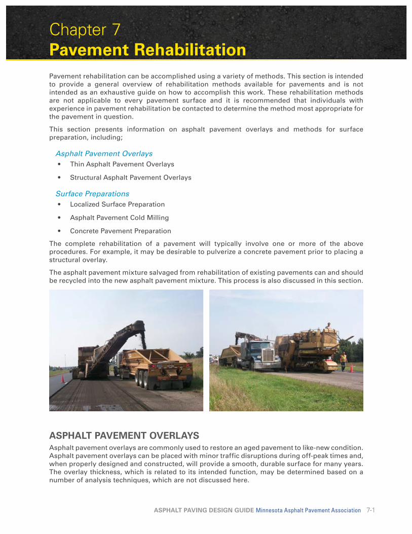
7-1ASPHALT PAVING DESIGN GUIDE Minnesota Asphalt Pavement Association
Chapter 7 Pavement RehabilitationPavement rehabilitation can be accomplished using a variety of methods. This section is intended to provide a general overview of rehabilitation methods available for pavements and is not intended as an exhaustive guide on how to accomplish this work. These rehabilitation methods are not applicable to every pavement surface and it is recommended that individuals with experience in pavement rehabilitation be contacted to determine the method most appropriate for the pavement in question.
This section presents information on asphalt pavement overlays and methods for surface preparation, including;
Asphalt Pavement Overlays• Thin Asphalt Pavement Overlays
• Structural Asphalt Pavement Overlays
Surface Preparations• Localized Surface Preparation
• Asphalt Pavement Cold Milling
• Concrete Pavement Preparation
The complete rehabilitation of a pavement will typically involve one or more of the above procedures. For example, it may be desirable to pulverize a concrete pavement prior to placing a structural overlay.
The asphalt pavement mixture salvaged from rehabilitation of existing pavements can and should be recycled into the new asphalt pavement mixture. This process is also discussed in this section.
ASPHALT PAVEMENT OVERLAYSAsphalt pavement overlays are commonly used to restore an aged pavement to like-new condition. Asphalt pavement overlays can be placed with minor traffic disruptions during off-peak times and, when properly designed and constructed, will provide a smooth, durable surface for many years. The overlay thickness, which is related to its intended function, may be determined based on a number of analysis techniques, which are not discussed here.

Chapter 7: Pavement Rehabilitation
7-2ASPHALT PAVING DESIGN GUIDE Minnesota Asphalt Pavement Association
Thin Asphalt Pavement OverlaysThin asphalt pavement overlays, usually placed in thicknesses of 2 inches or less, are used to protect a deteriorated pavement, reduce roughness, improve ride quality, and/or restore skid resistance. When thin asphalt pavement overlays are used, it is important to ensure that 1) the maximum size of the aggregate is appropriate for the overlay thickness, 2) a proper tack coat is applied, 3) work is carried out in warm weather to obtain the desired level of compaction, and 4) good construction quality control is maintained.
Structural Asphalt Pavement OverlaysStructural overlays are used to increase or restore the structural integrity of a pavement. Structural overlays may be required when a dramatic increase in heavy truck traffic is experienced or when existing pavements are approaching the end of their designed service life. Overlays will increase pavement life, reduce routine maintenance costs, provide a smoother riding surface, and improve skid resistance.
Structural Asphalt Pavement Overlay Design with NDTThe design of an asphalt pavement overlay requires that the existing structure, including the subgrade, be evaluated. The “strength” of the existing pavement structure gives an indication of both the thickness and condition of the pavement layers. Strength variability along the road can be determined by periodic measurements (every 100 ft or so) along the length of the roadway.
Over the past 20 years, Non-Destructive Testing (NDT) has been used to calculate the overall strength of individual pavement layers. Ground Penetrating Radar (GPR) can be used along with NDT to estimate pavement section layer thickness.
Devices used for NDT are the plate-bearing test, Benkleman beam, Dynaflect, Roadrater and the Falling Weight Deflectometer (FWD). The last three create a deflection basin, which makes it possible to determine the strength of individual layers. The individual tests take a matter of minutes to run and record electronically, so that a number of tests can be run along a roadway in a reasonable length of time.
NDT can also be used to screen for localized weak areas in order to complete remedial repair work before construction begins.
SURFACE PREPARATION METHODSTo ensure good performance of an asphalt pavement overlay, the existing pavement surface must be properly prepared. In general, uncorrected problems in the existing pavement surface will become problems in the asphalt pavement overlay. The type and extent of surface preparation should be carefully matched to the existing pavement condition and the asphalt pavement overlay type.

Chapter 7: Pavement Rehabilitation
7-3ASPHALT PAVING DESIGN GUIDE Minnesota Asphalt Pavement Association
Localized Surface PreparationLocalized surface preparation includes patching of deteriorated pavement areas and treatment of existing cracks.
Patching is one of the most common methods of repairing localized areas with intensive cracking (Alligator cracking) as a result of excessive loading or other factors. Patching may be either partial or full-depth.
Partial depth patching involves removal of only the surface layer and replacement with asphalt pavement. Full depth patching involves complete pavement removal down to stable material.
Regardless of the patch depth, it is important to remove the entire existing deteriorated pavement. Some areas of deterioration may not be visible on the surface but will become exposed during the removal process. In these cases, it is important to extend the patch boundaries to include these previously unseen areas of deterioration. Large cracks should be cleaned and filled with an asphalt pavement patching mixture.
Asphalt Pavement Cold MillingCold milling is the process of removing a desired thickness of pavement with a specially designed milling machine. A milling machine has a revolving drum mounted with carbide bits. These bits strike the pavement surface and remove the material (concrete or asphalt) to a predetermined depth. Pavement can be removed to any desired thickness.
Milling provides a level, textured surface, which has good skid resistance and provides an excellent bond with an overlay. Most pavement distortions, such as rutting, bumps and shoving, can be removed through milling without harming the underlying material. Milling makes it possible to maintain the original pavement elevations and drainage patterns. By removing material at the surface, no adjustments are required in the elevation at manholes, curbs and gutters, storm sewer inlets and other connecting pavement surfaces.
CONCRETE PAVEMENT PREPARATIONRehabilitation of existing pavements is the greatest pavement priority facing local, state and federal transportation agencies. Fracturing concrete pavement in place and then surfacing with asphalt pavement has been used successfully in Minnesota and nationally to provide a long-term and economical solution to the pavement rehabilitation problem and help reduce reflective cracking.

Chapter 7: Pavement Rehabilitation
7-4ASPHALT PAVING DESIGN GUIDE Minnesota Asphalt Pavement Association
The objective of the Crack and Seat technique is to greatly reduce reflective cracking in the asphalt pavement surfacing by reducing the effective slab length of the concrete pavement and is applicable to jointed plain concrete pavements (JPCP). The objective of Break and Seat is essentially the same, however more fracture energy is required as this is used on jointed reinforced concrete pavements (JRCP). Rubblization is applicable to all concrete pavement types and reduces the concrete panel to fragments that provide a strong foundation and eliminate or significantly reduce reflective cracks. Since Crack and Seat and Rubblization are more common in Minnesota, they are discussed further below. More information is also available on the National Asphalt Pavement Association (NAPA) web site.
Crack and SeatA concrete pavement that has good drainage and is still relatively sound can be salvaged through cracking and seating and then surfacing with an asphalt pavement. This option for rehabilitation is designed to reduce reflective cracking by decreasing the slab size of the concrete. Proper cracking and seating will greatly reduce reflective cracking. If reflective cracks should appear, they usually will be small, tight cracks that can be easily maintained.
With this method of rehabilitation, the concrete is cracked at 24- to 30-inch intervals with heavy drop hammer equipment to create a uniform pattern of cracking. Next, the cracked concrete pavement is seated with a rubber-tired roller of at least 35 tons. This seating action by the roller pushes down any pieces of concrete that might be over a void in the subbase. After the cracking and seating steps are completed, a 3-to 5-inch asphalt pavement surface is placed directly on the cracked and seated concrete. This method of recycling has been used for more than 30 years in many states; the first project in Minnesota using this technique was in 1959.
This method offers the following benefits:
1. Delays occurrence and reduces severity of reflective cracking.
2. Extends pavement service life.
3. Reduces maintenance costs.
4. Improves riding smoothness.
5. Is more cost-effective than removal and replacement.
6. Causes minimal disruption to traffic.
The procedural steps of the crack and seat process are:
1. Install necessary drainage.
2. Remove any existing overlay.
3. Saw cut the full thickness of the pavement adjacent to sections to remain in place.
4. Crack the concrete slabs.
5. Seat cracked slabs.
6. Remove and patch soft areas.
7. Sweep clean.
8. Place tack coat.
9. Place asphalt pavement.

Chapter 7: Pavement Rehabilitation
7-5ASPHALT PAVING DESIGN GUIDE Minnesota Asphalt Pavement Association
RubblizationThe rubblization of concrete pavements before surfacing with an asphalt pavement means the complete destruction of the concrete slab and of all concrete slab action. With this technique the concrete-to-steel bond is broken on all reinforced concrete pavements. The rubblization process effectively reduces the existing slab to a stable and strong in-place crushed aggregate base.
The benefits of this method are:
1. Eliminates or significantly reduces reflective cracking.
2. Provides a sound base.
3. Extends pavement service life.
4. Reduces maintenance costs.
5. Improves riding smoothness.
6. Is more cost-effective than removal and replacement.
7. Can be constructed one lane at a time, eliminating the need to divert traffic.
The procedural steps in the rubblization process are:
1. Install necessary drainage.
2. Remove any existing overlay.
3. Saw cut the full thickness of the pavement adjacent to sections to remain in place.
4. Rubblize the concrete pavement.
5. Cut off any exposed steel reinforcement.
6. Remove any loose patching material, joint fillers, expansion material, or similar from the rubblized surface.
7. Compact the rubblized concrete pavement.
8. Place asphalt pavement.

Chapter 7: Pavement Rehabilitation
7-6ASPHALT PAVING DESIGN GUIDE Minnesota Asphalt Pavement Association
Sawcut JointsOn PCC rehabilitation projects, sawing the asphalt pavement overlay over the underlying PCC joints will extend the overlay’s service life. Unless special procedures, such as crack/break and seat or pulverization, are used to prepare the existing PCC pavement, the joints will eventually reflect through the asphalt overlay. These cracks can occur within a short time, depending on factors such as the thickness of the overlay, volume of traffic, and conditions of the environment. Reflective cracking is caused by the underlying joints moving because of temperature and moisture changes, warping of the slab, and loading conditions that result in tensile, shear, and flexural forces greater than the strength of the pavement. This results in a crack in the overlay above the underlying joint.
Primary candidates for sawing of overlays over joints in the underlying PCC pavements are those overlays that have not lost structural integrity at the joints. Examples are overlays that are intended to increase structural capacity, correct skid resistance, prevent further scaling, or reduce noise.
To be effective, the sawcut in the overlay should be directly over the underlying joint. A maximum tolerance of 1 inch is required.
Reference marks that will not be obliterated during the overlay operation must be established at the underlying joint. The underlying joint must also be thoroughly cleaned and filled before overlaying.
BenefitsSawcut of the asphalt overlay is an effective technique to reduce the detrimental effect of uncontrolled reflective cracking over the underlying PCC joints. The sawcut and seal technique establishes a weakened plane joint in the overlay directly above the joint, and it can then be effectively sealed and maintained.
The technique of sawcut joints offers the following benefits:
1. Controls reflective cracking.
2. Provides maintainable joints.
3. Extends service life.
4. Controls maintenance costs.
5. Adjoining surface will be stronger than at the natural crack.
6. Better appearance.
7. Smoother riding pavement.
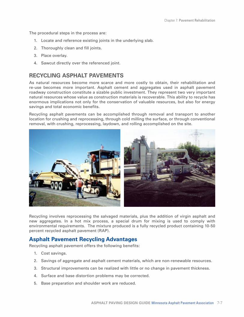
Chapter 7: Pavement Rehabilitation
7-7ASPHALT PAVING DESIGN GUIDE Minnesota Asphalt Pavement Association
The procedural steps in the process are:
1. Locate and reference existing joints in the underlying slab.
2. Thoroughly clean and fill joints.
3. Place overlay.
4. Sawcut directly over the referenced joint.
RECYCLING ASPHALT PAVEMENTSAs natural resources become more scarce and more costly to obtain, their rehabilitation and re-use becomes more important. Asphalt cement and aggregates used in asphalt pavement roadway construction constitute a sizable public investment. They represent two very important natural resources whose value as construction materials is recoverable. This ability to recycle has enormous implications not only for the conservation of valuable resources, but also for energy savings and total economic benefits.
Recycling asphalt pavements can be accomplished through removal and transport to another location for crushing and reprocessing, through cold milling the surface, or through conventional removal, with crushing, reprocessing, laydown, and rolling accomplished on the site.
Recycling involves reprocessing the salvaged materials, plus the addition of virgin asphalt and new aggregates. In a hot mix process, a special drum for mixing is used to comply with environmental requirements. The mixture produced is a fully recycled product containing 10-50 percent recycled asphalt pavement (RAP).
Asphalt Pavement Recycling AdvantagesRecycling asphalt pavement offers the following benefits:
1. Cost savings.
2. Savings of aggregate and asphalt cement materials, which are non-renewable resources.
3. Structural improvements can be realized with little or no change in pavement thickness.
4. Surface and base distortion problems may be corrected.
5. Base preparation and shoulder work are reduced.
Chapter 7: Pavement Rehabilitation
7-8ASPHALT PAVING DESIGN GUIDE Minnesota Asphalt Pavement Association
FDR and SFDRFull depth reclamation (FDR) and stabilized full depth reclamation (SFDR) of an in-place asphalt pavement have been defined as a recycling method where all of the asphalt pavement section and a predetermined amount of underlying materials are reclaimed in-place to produce a stabilized base course. Different types of additives, such as asphalt emulsions and chemical agents such as calcium chloride, portland cement, fly ash and lime, can be added to obtain an improved base. The five main steps in this process are pulverization, introduction of additive, shaping of the mixed material, compaction, and application of a surface or a wearing course. If the in-place material is not sufficient to provide the desired depth of the treated base, new materials may be imported and included in the processing. This method of recycling is normally performed to a depth of 4 to 12 in.
CIRCold in-place recycling (CIR) grinds off the top 2 to 6 inches of old asphalt pavement, crushes and screens it to size, mixes it with an asphalt recycling agent and sometimes other additives, then paves it on the same roadway. Topped with an asphalt overlay, the CIR lift can remove deep cracks to form a rut resistant base at a cost-effective price. It has been used when defects in the old pavement do not run the full depth of the old pavement, yet are too deep to be corrected with mill-and-fill or hot-in-place recycling. It should not be used when pavements have structural, drainage or base deficiencies. Deep failures should be addressed individually.
Chapter 8: Minnesota Mix Specifications, Methods & Quality Control 8-1
Asphalt Pavement Aggregate and Sizes 8-2Asphalt Pavement Mixture Types 8-4Warm Mix Asphalt 8-6Summary 8-6

8-1ASPHALT PAVING DESIGN GUIDE Minnesota Asphalt Pavement Association
Chapter 8 Minnesota Mix Specifications, Methods & Quality Control
This chapter of the Design Guide has been prepared to assist persons associated with designing and specifying Hot-Mix Asphalt. The objective is to understand the evolution of asphalt pavement technology in order minimize possible oversights in specifications and maximize the use of mixes designed to provide longer lasting asphalt pavement facilities.
Prior to 1997, there were two widely recognized methods of asphalt pavement design nationally, the Hveem and Marshall methods. Both of these design methods are named after their inventors and both describe a series of standardized tests and testing equipment used to determine the optimum aggregate and asphalt binder (liquid asphalt) blend needed for an asphalt mix to perform. The Marshall method of mix design is the most widely used and was the design method recognized by the Minnesota Department of Transportation.
There have been many changes to the types of asphalt pavement mixes used over the last ten years. These changes were needed to ensure asphalt pavement performance meets environmental conditions, usage demands, traffic volumes, and loads. Different mix criteria, aggregate types and sizes, and asphalt binder (liquid asphalt) have been instituted to meet these changes in asphalt pavement type. MnDOT has recently changed the specifications for asphalt pavement to primarily gyratory compactor designed mixes as opposed to the Marshall method. However, both methods (gyratory and Marshall) are still referenced in the MnDOT specifications.
One important source for new asphalt pavement design methods resulted from the Strategic Highway Research Program (SHRP). The SHRP was an unprecedented highway research undertaking including a $50 million element devoted to discovering a new design method that better simulated traffic loads expected in specific climatic regions around the nation. The products of the SHRP work were combined into an overall asphalt/aggregate mixture design and analysis system called Superpave, standing for Superior Performing asphalt Pavement.
It should be understood that Superpave is not a type of asphalt pavement. Superpave is a method (or process) of designing asphalt pavement. Just as the Marshall method, it can be used for mixture design but also for quality control (QC) and quality assurance (QA) activities. The Superpave design process is documented in publications from the Federal Highway Administration (FHWA), the Strategic Highway Research Program (SHRP), the Asphalt Institute (AI), AASHTO, ASTM and MnDOT. These publications should be used for detailed design information.
Two items developed from SHRP research into Superpave; first the gyratory compactor, and second a PG graded asphalt binder. The SHRP gyratory compactor is the newest piece of equipment used to compact mix samples in the Superpave mix design method. This equipment is used to determine proper blends of aggregates and binder (liquid) to complete an asphalt mix design appropriate for a certain facility.
The PG graded asphalt binder is a new method of specifying binder appropriate for the climate where the asphalt pavement is to be laid. The binder is tested to assure it gives enough flexibility during cold temperatures to resist cracking while providing the amount of rigidity needed during warmer temperatures to resist rutting. The type of PG graded asphalt binder used depends on the temperatures of the area, virgin vs. recycle mix, mix location of the various layer(s) of asphalt pavement in the pavement structure, and facility usage.
The choices in quality control (QC) and quality assurance (QA) remain the same for Superpave as for other mix technologies. MnDOT continues to use a full Quality Management (QM) Program for all their projects. This requires the contractor to perform all quality control testing of the asphalt pavement to ensure it meets the mix design for the project. The DOT then does quality assurance testing to monitor the contractor’s test results.
MAPA continues to encourage QM as a way to ensure the specifier is getting the best asphalt

Chapter 8: Minnesota Mix Specifications, Methods & Quality Control
8-2ASPHALT PAVING DESIGN GUIDE Minnesota Asphalt Pavement Association
pavement. We recognize, however, that you have all made choices in how much quality control testing is right for your facility or for your community. This choice remains correct, whether using the Marshall or the new Superpave (gyratory) compactor environment.
Should you wish to review any differences in the amount of type or testing on your project, please contact MAPA or your local MAPA member for clarification and assistance.
ASPHALT PAVEMENT AGGREGATE AND SIZESAggregates are defined as sand, gravel, crushed rock, ore tailings, mineral filler, or combinations of these materials. Aggregates make up 90-95 percent by weight of asphalt pavement. The quality of the aggregate is a critical factor in pavement performance along with the proper amount of binder (asphalt cement) for the intended purpose.
In addition to aggregate quality, there are other criteria that influence aggregate selection for a particular project such as cost and availability. An aggregate that meets cost and availability considerations (virgin or recycle) must still have certain properties to be considered suitable for use in quality asphalt pavement. These properties include:
Another characteristic of aggregate that affects mixture behavior is surface texture. However, there is currently no standard test method for evaluating surface texture directly. A non-polishing surface texture will maintain a higher coefficient of friction. With asphalt, coating or films cling more readily to rough or irregular surfaces than to smooth ones. Aggregate shape is a key to quality asphalt pavement by enhancing pavement strength and durability. Aggregates used in conjunction with binder materials can vary greatly depending on the intended usage. Each different material (source, class, kind, or size) can be uniformly fed at a uniform rate from its storage location to produce asphalt pavement.
• Maximum particle size
• Aggregate gradation
• Specific gravity
• Cleanliness
• Toughness
• Particle shape
• Absorption
• Moisture susceptibility
Specifications for gradation and quality of aggregates for various purposes provides for a blending of aggregate (coarse to fine) and in some cases a clean sand. The resulting mixture provides a very stable, durable mixture for usage in areas with heavy recreational traffic, driveways, tennis courts, pond liners, etc.
All asphalt pavement specifications require aggregate particles to be within a certain range of sizes, and for each size of particle to be present in a certain proportion. This distribution of various particle sizes within the aggregate used is called the aggregate, or mix, gradation. To determine whether or not an aggregate gradation meets specification requirements, an understanding of how particle size and gradation are measured is important.
Because specifications list a maximum particle size for each aggregate used, the size of the largest particles in the sample must be determined. There are two designations for maximum particle size:
• Nominal maximum particle size is designated as one sieve size larger than the first sieve to retain more than 10 percent in a standard series of sieves.
• Maximum particle size is defined as one sieve size larger than the nominal maximum particle size. Typically, this will be the smallest sieve through which 100 percent of the aggregate particles pass.
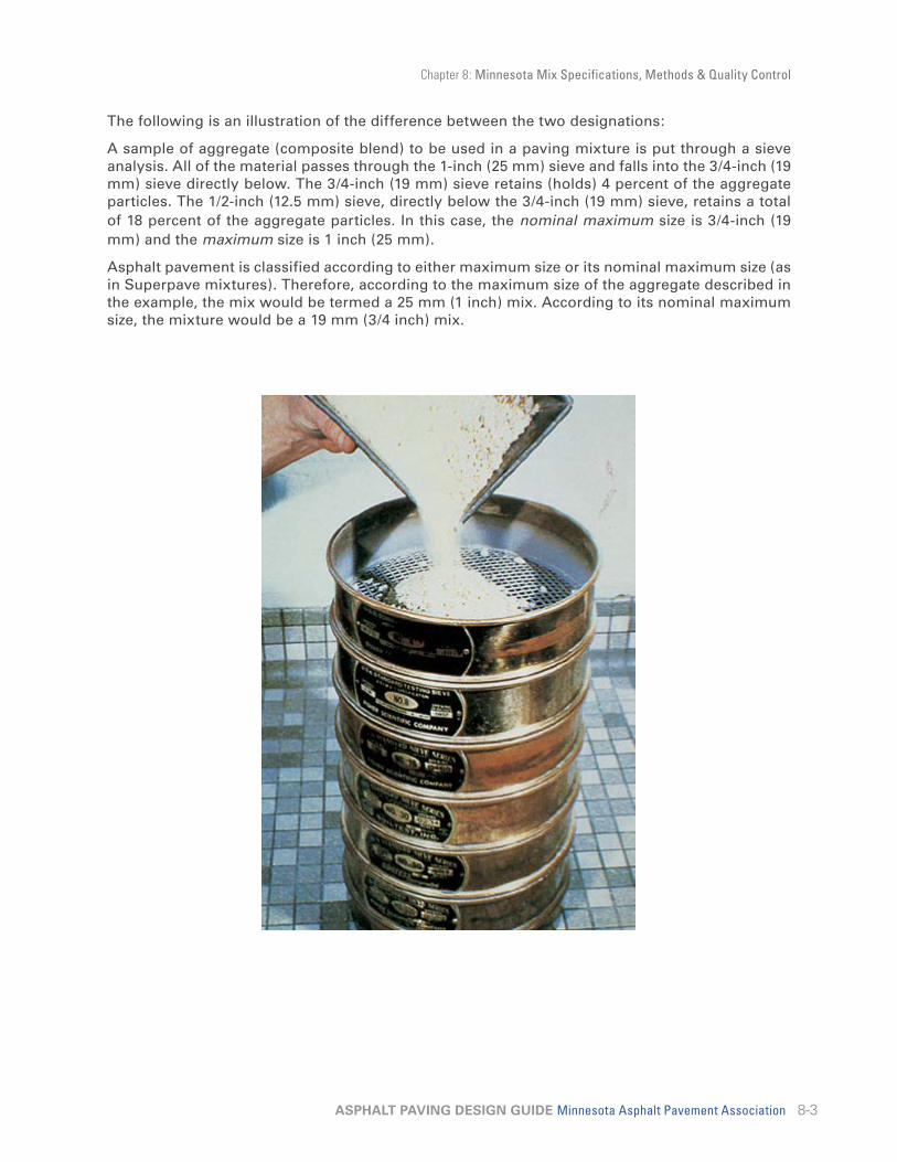
Chapter 8: Minnesota Mix Specifications, Methods & Quality Control
8-3ASPHALT PAVING DESIGN GUIDE Minnesota Asphalt Pavement Association
The following is an illustration of the difference between the two designations:
A sample of aggregate (composite blend) to be used in a paving mixture is put through a sieve analysis. All of the material passes through the 1-inch (25 mm) sieve and falls into the 3/4-inch (19 mm) sieve directly below. The 3/4-inch (19 mm) sieve retains (holds) 4 percent of the aggregate particles. The 1/2-inch (12.5 mm) sieve, directly below the 3/4-inch (19 mm) sieve, retains a total of 18 percent of the aggregate particles. In this case, the nominal maximum size is 3/4-inch (19 mm) and the maximum size is 1 inch (25 mm).
Asphalt pavement is classified according to either maximum size or its nominal maximum size (as in Superpave mixtures). Therefore, according to the maximum size of the aggregate described in the example, the mix would be termed a 25 mm (1 inch) mix. According to its nominal maximum size, the mixture would be a 19 mm (3/4 inch) mix.

Chapter 8: Minnesota Mix Specifications, Methods & Quality Control
8-4ASPHALT PAVING DESIGN GUIDE Minnesota Asphalt Pavement Association
PG BINDERSAsphalt cements (AC) can be graded or classified according to four different systems: 1) penetration, 2) viscosity, 3) viscosity after aging, and 4) performance grade (PG). The PG system has generally superseded the other systems and “binder” is the new name for asphalt cements – the glue that holds the aggregate together and makes it black. PG is short for “performance grade” and describes that the binder is rated on its performance at different temperatures.
Example: PG 58 - 28
58° Celsius1 -28° Celsius2
(136° F) to resist rutting (-18° F) to resist thermal cracking
(1) The average seven-day maximum temperature. (2) The minimum pavement temperature for a given region.
The Minnesota Asphalt Pavement Association recommends the following choices for your everyday needs:
• PG 58-28 or PG 64-22 (at contractor choice) for most pavement needs.
• PG 64-22 for higher volume uses such as major arterial streets, industrial streets or industrial lots.
MnDOT recognizes other additional binders that may also be appropriate for Minnesota. Most of these are binders that can only be purchased as modified. Modified binders are considerably more expensive than unmodified binders. This additional expense would not likely be appropriate or necessary for most normal projects.
There are special cases, however, that may require the use of modified binders. If you are specifying a pavement with extreme or unusual traffic conditions, please contact MAPA or your local MAPA contractor for further recommendations.
ASPHALT PAVEMENT MIXTURE TYPESThe durability and performance of an asphalt mixture is based on a correct volumetric proportioning of the ingredients comprising the mixture; namely aggregate, asphalt, and air. It is easy to forget this simple aspect due to the fact that all of the above ingredients, with the exception of air, are always proportioned by weight during mix formulation (laboratory and plant). This is basically why information regarding the specific gravity of the various components and of the resultant compacted mixture (Marshall and Gyratory) and uncompacted mixture is so important as it provides the means to determine volume from a known weight of material or vice-versa.
The methodology of asphalt mix design and production process control is one of determining the most economical aggregate combination available that provides a sufficient amount of voids in the mineral aggregate (VMA) at a specific compaction level (Marshall or Gyratory) to include the required percent air voids level and also an amount of binder (asphalt) volume (film thickness) to provide enough cohesion to maintain mix strength under traffic and environmental conditions.

Chapter 8: Minnesota Mix Specifications, Methods & Quality Control
8-5ASPHALT PAVING DESIGN GUIDE Minnesota Asphalt Pavement Association
For many years, aggregate shape was the least recognized of any other aggregate factor (i.e., quality, toughness, surface texture, absorption, crushing, etc.). This is probably because there is no standard procedure available which can measure this characteristic. There are procedures such as crushed content, elongated particle count, etc., but these are only quantitative evaluations of this aggregate characteristic. The only known method by which one can evaluate the influence of aggregate particle shape in an aggregate blend on mixture properties such as air voids and VMA is to manufacture a compacted mixture sample (Marshall or Gyratory) and determine the maximum specific gravity (Rice) in a controlled condition. The resulting specific gravity (ratio of the weight of an equal volume of water at a specified temperature) of a compacted laboratory sample is the net effect of aggregate gradation and aggregate shape together with a known amount of asphalt (binder). Thus aggregate shape can only be evaluated indirectly as part of the mixture design/quality control process.
In conclusion, aggregate gradation/aggregate properties – and thus mixture type, vary based on the intended asphalt pavement facility and its usage. The same is true for mixture volumetric parameters such as air voids and VMA. Generally speaking, specifications are oriented around traffic level and mixture criteria considering climatic conditions for the asphalt pavement to obtain the design life performance. Aggregate gradation and corresponding mixture properties can also be varied for such items as loading types, noise, friction, surface texture, appearance, porosity, etc.

Chapter 8: Minnesota Mix Specifications, Methods & Quality Control
8-6ASPHALT PAVING DESIGN GUIDE Minnesota Asphalt Pavement Association
WARM MIX ASPHALTWMA technologies reduce the viscosity of the material by using additives and foaming devices. These additives can be water-based, organic, chemical or hybrids. This allows for a lower temperature for the production process.
Benefits for the use of WMA technologies:
• Reduced energy consumption
• Reduced greenhouse gas emissions
• Improved working conditions at the paving site
• Cool weather paving
• Compaction aid
• Ability to extend the paving season
• Longer haul distances
• Potentially higher recycled asphalt pavement (RAP) percentages
For more information regarding warm mix asphalt see the NCHRP Report 691 at http://onlinepubs.trb.org/onlinepubs/nchrp/nchrp_rpt_691.pdf
SUMMARYMarshall and gyratory methods are both compactors for asphalt pavement and not a mixture type. The result of using either compactor or method is to design and control production of asphalt pavement that provides a long service life for an asphalt pavement facility. Criteria can be established to account for environment, traffic and optimum performing asphalt pavement with either the Marshall or gyratory compactor. In the future, it is likely that gyratory will be the most widely used system as advancements in technology, acceptance, product demands, and implementation continue to be made.
MAPA encourages the use of MnDOT's specifications on all applicable asphalt pavement construction projects in Minnesota. MnDOT's specifications have been developed with the involvement of other public agencies in Minnesota as well as with input from the industry. The use of standardized specifications can minimize confusion and misunderstanding. MnDOT's current specifications can be found on MnDOT's website at http://www.mrr.dot.state.mn.us/pavement/bituminous/bituminous.asp or by contacting MAPA at [email protected].
Glossary IMAPA Design Guide
List of Web Sites References IX
IASPHALT PAVING DESIGN GUIDE Minnesota Asphalt Pavement Association
Glossary
AAASHTO – The American Association of State Highway and Transportation Officials. An organization of highway engineers from the 50 states that develops guides and standards.
AGGREGATE – Any hard, inert, mineral material used for mixing in graduated fragments. It includes sand, gravel, crushed stone, or slag.
ALLIGATOR CRACKING – A series of interconnected cracks caused by failure of the asphalt pavement surface under repeated loads.
ASPHALT – A dark brown to black cementi-tious material that can be solid, semi-solid, or liquid in consistency, in which the predominant constituents are bitumens that occur in nature as such or are obtained as residue in refining petroleum. Asphalt is a constituent in varying proportions of most crude petroleums.
ASPHALT CEMENT BINDER (AC) – Asphalt that is refined to meet specifications for paving, industrial, and special purposes.
ASPHALT JOINT FILLER – An asphaltic product used for filling cracks and joints in pavement and other structures.
ASPHALT PAVEMENT – High quality, thoroughly controlled hot mixture of asphalt cement and well-graded, high-quality aggregate, thoroughly compacted into a uniform dense mass. Pavements consisting of a surface course of mineral aggregate coated and cemented together with asphalt cement on supporting courses such as asphalt bases, crushed stone, slag, or gravel.
ASPHALT PAVEMENT OVERLAY – One or more courses of asphalt pavement construction on an existing pavement. The overlay generally includes a leveling course to correct the contour of the old pavement, followed by a uniform course or courses to provide needed thickness.
ASPHALT PLANT – A manufacturing facility that produces asphalt pavement mixtures.
ASTM – The American Society for Testing and Materials. A national organization of users and producers of materials that establishes standards.
ASPHALT SURFACE TREATMENTS – Applications of asphaltic materials to any type of road or pavement surface, with or without a cover of mineral aggregate that produces an increase in thickness of less than 1 inch.
BBATCH PLANT – a manufacturing facility that produces asphalt pavement mixtures in batches.
BITUMINOUS (or Asphalt) CONCRETE – Other terms for asphalt pavement.
BLEEDING – A film of asphalt binder on the pavement surface caused by the upward migration of asphalt binder in an asphalt pavement resulting from a lack of air voids in the mixture or stripping in lower lying layers. Same as flushing.
BORROW – Suitable material from sources outside the roadway prism used primarily for embankments.
BREAK & SEAT – A process used to reduce joint reflective cracking in an asphalt pavement overlay over old PCC pavement. It involves breaking up the underlying rigid pavement into relatively small pieces by repeatedly dropping a heavy weight or hammer and then seating the broken slab with a roller.
CCBR (California Bearing Ratio) – A measurement of the strength and support value of a crushed stone base or subgrade soil.
CAPILLARY ACTION – The rise or movement of water in the voids of a soil caused by capillary
Glossary
IIASPHALT PAVING DESIGN GUIDE Minnesota Asphalt Pavement Association
forces.
CEMENT-TREATED BASE – A cement-treated base consists of a specified soil aggregates and Portland cement concrete mixed in a pug mill and deposited on the subgrade to the specified thickness.
COARSE AGGREGATE – Aggregate particles retained on a No. 8 sieve.
COARSE GRADED AGGREGATE – Aggregate having a predominance of coarse sizes.
COMPACTION – The densification of crushed stone base, subgrade soil, or asphalt pavement material by means of vibration or rolling.
COMPACTIVE EFFORT – The combined effort of (1) applying weight to an asphalt pavement surface with a roller and compressing the material underneath the ground contact area and (2) creating a shear stress between the compressed material underneath the ground contact area and the adjacent uncompressed material.
CONTRACT – The written agreement executed between the contractor and other parties, setting forth the obligations of the parties thereunder; including, but not limited to the performance of the work, the furnishing of labor and materials, and a basis of payment.
CONTRACTOR – The individual, partnership, corporation, or joint venture contracted to perform the prescribed work.
CRUDE OIL – Unrefined petroleum.
CRUSHED STONE – The product resulting from the artificial crushing of rocks, boulders, or large cobblestones with the particles resulting from the crushing operation having all faces fractured.
CRUSHER RUN – Aggregates that have received little or no screening after initial crushing operations. Crusher run aggregates are generally more economical than screened aggregates.
CUL-DE-SAC – An area at the end of a street or road constructed for the purpose of allowing a
vehicle to turn around.
CULVERT – Any structure that is not classified as a bridge and provides an opening under a roadway.
CUT – The portion of the roadway formed by excavation below the existing surface of the earth.
CUTBACK ASPHALT – Asphalt cement liquefied by blending with petroleum solvents. Upon exposure to atmospheric conditions, the solvents evaporate, leaving the asphalt cement to perform its function.
DDESIGN THICKNESS – The total pavement structure thickness above the subgrade.
DENSE GRADED AGGREGATE – Aggregate uniformly graded from the maxi-mum size down to and including sufficient mineral dust to reduce the void space in the compacted aggregate to exceedingly small dimensions.
DRAINAGE – Structures used for collecting and carrying away water.
DRUM PLANT – A manufacturing facility that produces asphalt pavement mixtures in the dryer drum on a continuous basis.
EEARTHWORK – The work consisting of the construction of the roadway, excluding bridges, pavement structure, and selected or capping material.
EMBANKMENT – A structure of soil, soil aggregate, or broken rock between the embankment foundation and the subgrade.
EMULSIFIED ASPHALT – An emulsion of asphalt cement and water that contains a small amount of an emulsifying agent, a heterogeneous system containing two normally immiscible phases (asphalt and water), in which the water forms the continuous phase of the emulsion and minute globules of asphalt form
Glossary
IIIASPHALT PAVING DESIGN GUIDE Minnesota Asphalt Pavement Association
the discontinuous phase. Emulsified asphalts may be either anionic (electro-negatively-charged asphalt globules) or cationic (electro-positively-charged asphalt globules) depending upon the emulsifying agent.
EQUIPMENT – All machinery, tools, and other apparatus, together with the necessary supplies for upkeep and maintenance, needed for the proper construction and acceptable completion of the work.
EROSION – Removal and transportation of soil by water or wind.
ESAL – Equivalent Single Axle Load. Based on the AASHTO Road Test, the most common approach to determining traffic loading is to convert wheel loads of various magnitudes and repetitions to an equivalent number of “standard” or “equivalent” loads. The most commonly used equivalent load in the U.S. is the 18,000-lbs. single-axle load.
FFATIGUE CRACKING – Cracks caused by fatigue failure of an asphalt pavement surface under repeated loads.
FINE AGGREGATE – Aggregate particles passing a No. 8 sieve.
FINE GRADED AGGREGATE – Aggregate having a predominance of fine sizes.
FHWA – Federal Highway Administration, part of the U.S. Department of Transportation.
FLEXIBLE PAVEMENT – A pavement structure that maintains intimate contact with and distributes loads to the subgrade and depends on aggregate interlock, particle friction, and cohesion for stability. Asphalt pavements are flexible pavements; PCC concrete is not.
FLUSHING – A film of asphalt binder on the pavement surface caused by the upward migration of asphalt binder in an asphalt pavement resulting from a lack of air voids in the mixture or stripping in lower lying layers. Same as bleeding.
FOG SEAL – A light application of liquid asphalt without mineral aggregate cover. Slow-setting asphalt emulsion diluted with water is the preferred type.
FREE WATER (GROUNDWATER) – Water that is free to move through a soil mass under the influence of gravity.
FRENCH DRAIN – A trench loosely backfilled with stones, the largest being placed on the bottom with the size decreasing toward the top.
FULL-DEPTH ASPHALT PAVEMENT – An asphalt pavement in which asphalt pavement mixtures are employed for all layers above the subgrade or improved subgrade. A full-depth asphalt pavement is laid directly on the prepared subgrade.
FWD – A Falling Weight Deflectometer is an impact load device used to deliver a transient impulse load to the pavement surface and measure the resultant pavement response (deflection) by a series of sensors.
GGEOTEXTILES – Fabric-like materials used in some pavement construction applications. Uses include stabilization of base materials to prevent migration into subgrades.
GRAVEL – A coarse granular material (usually larger than 1/4 inch in diameter) resulting from the natural erosion and disintegration of rock. In Minnesota, most gravel is of glacial origin. Crushed gravel is the result of artificial crushing with most fragments having at least one face resulting from fracture.
GRANULAR BORROW – Granular Material used to replace undesirable materials in the grade for a pavement.
lICE LENS – Subsurface ice crystals that form in the plane of freezing temperatures of a pavement. Water migrates from below (where the temperature is above freezing) and freezes.

Glossary
IVASPHALT PAVING DESIGN GUIDE Minnesota Asphalt Pavement Association
Heaving of the pavement surface can result if the creation of an ice lens is significant.
IMPROVED SUBGRADE – Any layer of select or improved material between the foundation soil and the subbase is usually referred to as the improved subgrade. The improved subgrade can be made up of two or more layers of different quality materials.
IN SITU – In place, or in it’s original location.
JJMF – Job-Mix Formula is a recommended/ approved proportion of aggregate & asphalt used for field Quality Control/Quality Assurance of asphalt pavement mixture production.
LLIFT – A layer or course of asphalt paving material.
LEVELING COURSE – An asphalt/aggregate mixture of variable thickness used to eliminate irregularities in the contour of an existing surface before superimposed treatment or construction.
LIQUID ASPHALT – An asphalt material having a soft or fluid consistency that is beyond the range of measurement by the normal penetration test, the limit of which is 300 maximum. Liquid asphalts include cutback asphalt and emulsified asphalts.
MMAPA – The Minnesota Asphalt Pavement Association.
MAT – A term used to describe the fresh asphalt pavement surface behind the paving machine. It is most commonly used to refer to the asphalt pavement layer during the laydown and compaction phase of construction.
MATERIALS – Any substances specified for use in the construction of the project and its
appurtenances.
MEDIUM CURING ASPHALT (MC) – Liquid asphalt composed of asphalt cement and a kerosene-type diluent of medium volatility.
MINERAL DUST – The portion of the fine aggregate passing a No. 200 sieve.
MINERAL FILLER – A finely divided mineral product at least 65 percent of which will pass a No. 200 sieve. Pulverized limestone is the most common manufactured filler, although other stone dust, hydrated lime, Portland cement, and certain natural deposits of finely divided mineral matter are also used.
NNAPA – The National Asphalt Pavement Association.
NATURAL ASPHALT – Asphalt occurring in nature that has been derived from petroleum by natural processes of evaporation of volatile fractions leaving the asphalt fractions. The native asphalts of most importance are found in the Trinidad and Bermudez Lake deposits. Asphalt from these sources is called Lake Asphalt.
NCAT – the National Center for Asphalt Research and Technology located at Auborn University in Auborn, Alabama.
OOPEN GRADED AGGREGATE – An aggregate containing little or no mineral filler or in which the void spaces in the compacted aggregate are relatively large.
OPTIMUM MOISTURE CONTENT – In a soil, the moisture content at which maximum density can be achieved.
PPAVEMENT STRUCTURE (COMBINATION OR COMPOSITE) – All courses of selected

Glossary
VASPHALT PAVING DESIGN GUIDE Minnesota Asphalt Pavement Association
material placed on the foundation or subgrade soil, other than any layers or courses constructed in grading operations. When the asphalt pavement is on an old concrete base or other rigid-type base, the pavement structure is referred to as a combination or composite-type pavement structure.
PERCOLATION – The movement of free water through soil.
PERMEABILITY – A measure of the rate or volume of flow of water through a soil or other material including asphalt pavement.
PERPETUAL PAVEMENT – A Long-lasting asphalt pavement.
PETROLEUM ASPHALT – Asphalt refined from crude petroleum.
PLANS – The standard drawings current on the date bids are received; and the official approved plans, profiles, typical cross sections, electronic computer output listings, working drawings and supplemental drawings, or exact reproductions thereof, current on the date bids are received; and all subsequent approved revisions thereto, which show the location character, dimensions, and details of the work to be done.
PLANT MIX – An asphalt pavement mixture produced in an asphalt mixing plant, that consists of mineral aggregate uniformly coated with asphalt cement or liquid asphalt.
POROUS ASPHALT – A pavement designed to allow water to drain all the way through the pavement structure.
PORTLAND CEMENT CONCRETE (PCC) – A composite material that consists essentially of Portland cement and water as a binding medium in which is mixed coarse and fine particles of crushed stone.
POTHOLE – A bowl-shaped opening in the pavement surface resulting from localized disintegration.
PSI – Present Serviceability Index is a pavement condition index.
PSR – Present Serviceability Rating is a definition of pavement serviceability based on individual observation.
PUMPING – Pavement deflection at a joint or crack under traffic that results in a discharge of water and/or subgrade soils.
PROPOSAL – The offer of a bidder, submitted on the approved official form, to perform the work and to furnish the labor and material at prices set forth therein, valid only when properly signed and guaranteed.
Q QUALITY ASSURANCE (QA) – A system, including physical tests, that assures that the material being supplied to a construction project substantially complies with the contract requirements.
QUALITY CONTROL (QC) – A system, including physical tests, that is used by the contractor to control production operations to ensure contract compliance.
QUALITY MANAGEMENT – A system incorporating QC & QA that was developed in Minnesota to control the production of and to facilitate acceptance of asphalt pavements.
RRAPID CURING ASPHALT (RC) – Liquid asphalt composed of asphalt cement and a naphtha- or gasoline-type diluent of high volatility.
REHABILITATION – The renewal of an existing surface or pavement structure by repair, recycling, or overlay techniques.
RECLAIMED or RECYCLED ASPHALT PAVEMENT (RAP) – Removed and/or reprocessed pavement materials containing asphalt and aggregates.
REFLECTIVE CRACKING – Cracks in an overlay caused by cracks in the existing pavement “reflecting” up through the overlay.

Glossary
VIASPHALT PAVING DESIGN GUIDE Minnesota Asphalt Pavement Association
RESILIENT MODULUS – An estimate of a materials elastic modulus based on the stress and strain measurements from rapidly applied loads – like those that pavement materials experience from wheel loads.
RESURFACING – Existing surfaces may be improved by resurfacing (or overlaying) with an asphalt pavement mat of varying thicknesses. It may be considered in two categories: (1) overlays to provide smooth, skid- and water resistant surfaces or to make improvements in grade and/or cross section; and (2) overlays to strengthen existing pavements to handle heavier loads or increased traffic.
RICE TEST – Rice Density or Rice Specific Gravity is a test used to determine the maximum specific gravity or the zero voids density of a mixture used in calculating the volume of air voids in a compacted asphalt pavement mixture.
RIGID PAVEMENT – A pavement structure that distributes loads to the subgrade by slab action with a Portland cement concrete slab of relatively high bending resistance.
ROAD – A general term denoting a public way for purpose of vehicular travel, including the entire area within the right-of-way.
ROADBED – The graded portion of a highway within the top and side slopes, prepared as a foundation for the pavement structure and shoulders.
ROCK – From which crushed stone, sand, and gravel are made; the rock most suitable for making good aggregates.
RUBBLIZATION – Reducing a material or structure to rubble. Regarding pavements, rubblization usually refers to reducing an existing rigid pavement to rubble in preparation for an asphalt pavement overlay to effectively reduce reflective cracks.
RUTTING – Surface depressions in the wheelpath of a pavement.
S
SCREED – The part of a paving machine that spreads, smooths and provides initial compaction of the asphalt pavement mat.
SEAL COAT – A thin asphalt surface treatment used to waterproof and improve the texture of an asphalt wearing surface. Depending on the purpose, seal coats may or may not be covered with aggregate. The main types of seal coats are aggregate seals, fog seals, emulsion slurry seals, and sand seals.
SEGREGATION – Regarding asphalt pavement, the broad definition is “a lack of homogeneity in the constituents in the asphalt pavement mat being placed of such a magnitude that there is a reasonable expectation of accelerated pavement distress. Typically though, “segregation” refers to aggregate segregation, which is “the non-uniform distribution of coarse and fine aggregate components within the asphalt pavement mixture”.
SELECT MATERIAL – Suitable material obtained from roadway cuts, borrow areas, or commercial sources and designated or reserved for use as foundation for the subbase, for subbase material, shoulder surfacing, or other specific purposes.
SHOULDER – The portion of the roadway contiguous with the traveled way for accommodation of stopped vehicles, for emergency use, and for lateral support of base and surface courses.
SHOVING – A form of plastic movement or flow typified by an abrupt wave across the pavement surface. The distortion is perpendicular to the traffic direction.
SHRP – Strategic Highway Research Program.
SKID RESISTANCE – The ability of a pavement surface to offer resistance to slipping or skidding for vehicle tires.
SLOW CURING ASPHALT (SC) – Liquid asphalt composed of asphalt cement and oils of low volatility.
SLAG – The air-cooled, non-metallic by-product of a blast furnace operation consisting

Glossary
VIIASPHALT PAVING DESIGN GUIDE Minnesota Asphalt Pavement Association
essentially of silicates and aluminosilicates of lime and other bases that is developed simultaneously with iron in a blast furnace. Naturally it is only available in those localities where pig iron is produced. Crushed slag weighs about 80 pounds per cubic foot.
SOIL AGGREGATE – Natural or prepared mixtures consisting predominantly of hard, durable particles or fragments of stone, slag, gravel, or sand, that contain some soil-clay or stone dust conforming to specified requirements.
SOIL CEMENT BASE – Consists of a mixture of the natural subgrade material and Portland cement in the proper amounts. After thorough mixing, the proper amount of water is added, and the material is compacted to the required thickness.
SOIL SUPPORT – A term expressing the ability of the roadbed material, or subgrade soil, to support the traffic loads transmitted through a flexible pavement structure.
SPECIAL PROVISIONS – Special directions, provisions, or requirements specific to the project under consideration and not otherwise thoroughly or satisfactorily detailed or set forth in the specifications. Special provisions set forth the final contractual intent in the matter involved.
STAGE CONSTRUCTION – The construction of roads and streets by applying successive layers of asphalt pavement according to design and a predetermined time schedule.
STREET – A general term denoting a public way for purpose of vehicular travel, including the entire area within the right-of-way.
SUBBASE – The course in the asphalt pavement structure immediately below the base course is the subbase. If the subgrade soil is of adequate quality, it may serve as the subbase.
SUBCONTRACTOR – Any individual, partnership, or corporation to whom the contractor sublets part of the contract.
SUBDRAIN – A structure placed beneath the ground surface to collect and carry away
underground water.
SUBGRADE – The uppermost material placed in embankments or unmoved from cuts in the normal grading of the roadbed. It is the foundation for the pavement structure. The subgrade soil sometimes is called basement soil or foundation soil.
SUBGRADE STABILIZATION – Modification of roadbed soils by admixing with stabilizing or chemical agents that will increase load-bearing capacity, firmness, and resistance to weathering or displacement.
SURFACE COURSE – One or more layers of a pavement structure designed to accommodate the traffic load, the top layer of which resists skidding, traffic abrasion, and the disintegrating effects of climate. The top layer is some-times called the ‘wearing course.’
SUBSURFACE DRAINAGE – Removal of free water from various structural components of the pavement or the surrounding soil.
SUPERPAVE – Superior Performing Asphalt Pavements is an overarching term for the results of the asphalt research portion of the 1987-1993 Strategic Highway Research Program (SHRP). Superpave consists of (1) an asphalt binder specification, (2) an asphalt pavement mixture design method and (3) asphalt pavement tests and performance prediction models. Each one of these components is referred to by the term “Superpave”
TTACK COAT – Asphalt material, usually an emulsion, applied to an existing pavement surface prior to repair or the placement of subsequent layers of asphalt pavement to create a bond between the old and the new mixtures.
TEST STRIP – A small section of mat laid at the beginning of a project with the purpose of determining the best roller type, sequence number of passes and rolling pattern to use.
THERMAL CRACKING – Cracking caused by

Glossary
VIIIASPHALT PAVING DESIGN GUIDE Minnesota Asphalt Pavement Association
shrinkage of the pavement structure due to low temperatures.
UUNDERDRAIN – A perforated or porous-walled pipe placed with suitable pervious backfill beneath the ground surface to collect and carry away underground water.
VVISCOSITY – This is a measure of the resistance to flow. The term is used as “high viscosity” or “low viscosity.” A high viscosity material refers to a heavy or still material that will not flow easily. A low viscosity material is the opposite. Viscosity is measured in absolute units called poises. It was formerly measured in empirical values of time, distance, and temperature. This method was called Saybolt Furol Viscosity.
VMA – Voids in Mineral Aggregates (VMA) is the volume of intergranular void space between the aggregate particles of a compacted paving mixture that includes the volume of air voids and the volume of the effective asphalt content, expressed as a percentage of the total volume of the specimen.
WWARM MIX ASPHALT – (commonly abbreviated as WMA) is produced by adding either zeolites, waxes, asphalt emulsions, or water to the asphalt binder prior to mixing. This allows significantly lower mixing and laying temperatures and results in lower consumption of fossil fuels, thus releasing less carbon dioxide, aerosols and vapors.
WEARING COURSE – The top course of asphalt pavements, also called the surface course.
WHEELPATH – That portion of a pavement that is contacted by the wheels/tires of vehicles in a typical traffic stream. There are generally two wheelpaths per lane.
WORKABILITY – Regarding asphalt pavement, a term that refers to an asphalt pavement’s ability to be placed and compacted. Workable mixes are easy to place and compact and are generally more viscous than mixes with poor workability.

IXASPHALT PAVING DESIGN GUIDE Minnesota Asphalt Pavement Association
MAPA Design Guide List of Web Sites ReferencesAmerican Association of State Highway and Transportation Officials (AASHTO) www.aashto.org
American Public Works Association (APWA) www.pubworks.org
American Road & Transportation Builders Association (ARTBA) www.artba.org
American Society for Testing Materials (ASTM) www.astm.org
American Traffic Safety Association www.atssa.com
Asphalt Institute www.asphaltinstitute.org
Asphalt Pavement Alliance www.asphaltroads.org
Asphalt Paving Association of Iowa www.apai.net
Center for Transportation Studies, University of Minnesota www.cts.umn.edu
Dakota Asphalt Pavement Association (DAPA) www.dakota-asphalt.org
Local Road Research Board (LRRB) www.lrrb.gen.mn.us
Minnesota County Engineers Association (MCEA) www.mcea.gen.mn.us
Minnesota Asphalt Pavement Association (MAPA) www.asphaltisbest.com
Minnesota Department of Transportation (MnDOT) www.dot.state.mn.us
Minnesota Pollution Control Agency (MPCA) www.pca.state.mn.us
National Asphalt Pavement Association (NAPA) www.asphaltpavement.org
National Center for Asphalt Technology www.ncat.us
North Central Superpave Center http://engineering.purdue.edu/NCAC
Occupational Health & Safety Administration (OSHA) www.osha.gov
Transportation Research Board www.nas.edu/trb/
U.S. Department of Transportation (USDOT) www.dot.gov
USDOT Transportation Safety Institute www.tsi.dot.gov
USDOT Federal Highway Administration (FHWA) www.fhwa.dot.gov
United States Tennis Association www.usta.com
United States Tennis Court & Track Builders Association www.ustctba.com
Wisconsin Asphalt Pavement Association (WAPA) www.wispave.org