Embed Size (px)
Citation preview

13t
TMode
th Internatio
W
A
ThirdIelBased
o
Organonal Confer
SteIle
Thomas WeiIu
Worksh
CES
InternadArchiofEmbe
October 4t
nized in conence on Mo
fan Van Baeleneana Ober (Univ
Huascar Espgert (Missouri Ulian Ober (UnivSébastien Gér
hopProc
SMB2
ationalitectingeddedS
th, 2010, Os
njunction wodel Driven
Edited by:n (K.U.Leuven ‐versity of Toulopinoza (ESI TecUniversity of Scversity of Toulorard (CEA – LIST
ceeding
201
WorksgandCSystem
slo, Norway
ith MoDELS Engineerin
DistriNet, Belgiouse ‐ IRIT, Frannalia, Spain) cience and Techuse ‐ IRIT, FranT/LISE, France)
s
10
shoponConstrums
S 2010 ng Language
ium) nce)
hnology, USA) ce)
nuction
es and Syste
ems

TableofContents
Table of Contents .....................................................................................................................................3
Foreword ..................................................................................................................................................5
Acknowledgments ...................................................................................................................................7
Invited Talk ‐ Using Metaheuristic Search for the Analysis and Verification of UML Models
Lionel C. Briand (Simula Research Laboratory & University of Oslo, Norway) ....................................9
Mapping the MARTE UML Profile to AADL
Skander Turki, Eric Senn and Dominique Blouin (Université de Bretagne‐Sud, France) ................... 11
A Time‐Centric Model for Cyber‐Physical Applications
John C. Eidson, Edward A. Lee, Slobodan Matic, Sanjit A. Seshia and Jia Zou (University of California at Berkeley, USA) ............................................................................................................................... 21
From Interaction Overview Diagrams to Temporal Logic
Luciano Baresi, Angelo Morzenti, Alfredo Motta and Matteo Rossi (Politecnico di Milano, Italy) .. 37
Virtual Verification of System Designs against System Requirements
Wladimir Schamai (EADS Innovation Works, Germany), Philipp Helle (EADS Innovation Works, UK), Peter Fritzson (Linköping University, Sweden) and Christiaan J.J. Paredis (Georgia Institute of Technology, USA) .............................................................................................................................. 53
Approach for Iterative Validation of Automotive Embedded Systems
Gereon Weiss, Marc Zeller, Dirk Eilers and Rudi Knorr (Fraunhofer ESK, Germany) ....................... 69
Model Maturity Levels for Embedded Systems Development, or: Working with Warnings
Martin Groβe‐Rhode (Fraunhofer ISST, Germany) ........................................................................... 85
Towards a Systematic Approach for Software Synthesis
Hamid Bagheri and Kevin Sullivan (University of Virginia, USA) ..................................................... 101
Toward Mega Models for Maintaining Timing Properties of Automotive Systems
Stefan Neumann and Andreas Seibel (University of Potsdam, Germany) ...................................... 107
A Transformation‐based Model of Evolutionary Architecting for Embedded System Product Lines
Jakob Axelsson (Mälardalen University, Sweden) ........................................................................... 113
Identifying Features for Ground Vehicles Software Product Lines by Means of Annotated Models
Rafael S. Durelli, Daniel B. F. Conrado (UFSCAR, Brazil), Ricardo A. Ramos (UNIVASF, Brazil), Oscar L. Pastor (UPV, Spain), Valter V. de Camargo and Rosângela A. D. Penteado (UFSCar, Brazil) .......... 119
Product Line Development using Multiple Domain Specific Languages in Embedded Systems
Susumu Tokumoto (Fujitsu Laboratories Limited, Japan) ................................................................... 125
MoDELS 2010 ACES-MB Workshop Proceedings
Oslo, Norway, October 4, 2010 3

Foreword
The development of embedded systems with real‐time and other critical constraints raises distinctive problems. In particular, development teams have to make very specific architectural choices and handle key non‐functional constraints related to, for example, real‐time deadlines and to platform parameters like energy consumption or memory footprint. The last few years have seen an increased interest in using model‐based engineering (MBE) techniques to capture dedicated architectural and non‐functional information in precise (and even formal) domain‐specific models in a layered construction of systems. MBE techniques are interesting and promising for the following reasons: They allow to capture dedicated architectural and non‐functional information in precise (and even formal) domain‐specific models, and they support a layered construction of systems, in which the (platform independent) functional aspects are kept separate from architectural and non‐functional (platform specific) aspects, where the final system is obtained by combining these aspects later using model transformations.
The objective of this workshop is to bring together researchers and practitioners interested in model‐based engineering to explore the frontiers of architecting and construction of embedded systems. We are seeking contributions relating to this subject at different levels, from modelling languages and semantics to concrete application experiments, from model analysis techniques to model‐based implementation and deployment. Given the criticality of the application domain, we particularly focus on model‐based approaches yielding efficient and provably correct designs. Concerning models and languages, we welcome contributions presenting novel modelling approaches as well as contributions evaluating existing ones. The workshop targets in particular:
• Architecture description languages (ADLs). Architecture models are crucial elements in system and software development, as they capture the earliest decisions which have a huge impact on the realization of the (non‐functional) requirements, the remaining development of the system or software, and its deployment. We are particularly interested in examining:
o Position of ADLs in an MDE approach; o Relations between architecture models and other types of models used
during requirement engineering (e.g., SysML, EAST‐ADL, AADL), design (e.g., UML), etc.;
o Techniques for deriving architecture models from requirements, and deriving high‐level design models from architecture models;
o Verification and early validation using architecture models.
MoDELS 2010 ACES-MB Workshop Proceedings
Oslo, Norway, October 4, 2010 5

• Domain specific design and implementation languages. To achieve the high confidence levels required for critical embedded systems through analytical methods, in practice languages with particularly well‐behaved semantics are often used, such as synchronous languages and models (Lustre/SCADE, Signal/Polychrony, Esterel), super‐synchronous models (TTA, Giotto), scheduling‐friendly models (HRT‐UML, Ada Ravenscar), or the like. We are interested in examining the model‐oriented counterparts of such languages, together with the related analysis and development methods.
• Languages for capturing non‐functional constraints (MARTE, AADL, OMEGA, etc.) • Component languages and system description languages (SysML, MARTE, EAST‐ADL,
AADL, BIP, FRACTAL, Ptolemy, etc.).
We accepted 11 papers for the workshop from 10 different countries: 6 full papers and 5 position papers. We hope that the contributions for the workshop and the discussions during the workshop will help to contribute and provide interesting new insights in Model Based Architecting and Construction of Embedded Systems.
The ACESMB 2010 organising committee,
Stefan Van Baelen, Ileana Ober, Huascar Espinoza, Thomas Weigert, Iulian Ober, Sébastien Gérard.
The ACESMB 2010 steering committee,
Mamoun Filali, Susanne Graf.
September 2010.
MoDELS 2010 ACES-MB Workshop Proceedings
Oslo, Norway, October 4, 2010 6
Acknowledgments
The Organising Committee of ACESMB 2010 would like to thank the workshop Programme Committee for their helpful reviews.
Nicolas Belloir (LIUPPA, France) Jean‐Michel Bruel (IRIT, France) Agusti Canals (CS‐SI, France) Daniela Cancila (Sherpa Engineering, France) Arnaud Cuccuru (CEA‐LIST/LISE, France) Huascar Espinoza (ESI Tecnalia, Spain) Jean‐Marie Farines (UFSC, Brasil) Peter Feiler (SEI, USA) Mamoun Filali (IRIT, France) Robert France (CSU, USA) Sébastien Gérard (CEA LIST/LISE, France) Susanne Graf (VERIMAG, France) Bruce Lewis (US Army, USA) Ileana Ober (IRIT, France) Iulian Ober (IRIT, France) Isabelle Perseil (Telecom ParisTech, France) Dorina Petriu (Carleton University, Canada) Andreas Prinz (University of Agder, Norway) Bernhard Rumpe (RWTH Aachen, Germany) Douglas C. Schmidt (Vanderbilt University, USA) Bran Selic (Malina Software, Canada) Jean‐Bernard Stefani (INRIA Rhône‐Alpes, France) Martin Törngren (KTH, Sweden) Stefan Van Baelen (K.U.Leuven DistriNet, Belgium) Tullio Vardanega (University of Padua, Italy) Eugenio Villar (Universidad de Cantabria, Spain) Thomas Weigert (Missouri S&T, USA) Tim Weilkiens (OOSE, Germany) Sergio Yovine (VERIMAG, France)
This workshop is organised as an event in the context of
• The IST‐004527 ARTIST2 Network of Excellence on Embedded Systems Design • The research project EUREKA‐ITEA EVOLVE (Evolutionary Validation, Verification and
Certification) • The research project EUREKA‐ITEA VERDE (Validation‐driven design for component‐based
architectures) • The research project EUREKA‐ITEA OPEES (Open Platform for the Engineering of Embedded
Systems) • The research project ICT‐INTERESTED ((INTERoperable Embedded Systems Tool chain for
Enhanced rapid Design, prototyping and code generation)
MoDELS 2010 ACES-MB Workshop Proceedings
Oslo, Norway, October 4, 2010 7


Invited Talk
Using Metaheuristic Search for the Analysis and
Verification of UML Models
Lionel C. Briand
Simula & University of Oslo, Oslo, Norway
Abstract. There is a growing research activity around the use of meta-
heuristic search techniques (e.g., genetic algorithms) in software engi-
neering, for example to support test case generation. This is often re-
ferred to as search-based software engineering and is the subject of an
international conference every year. This presentation will reflect on sev-
eral years of research, involving several collaborators, that has focused
on using metaheuristic search to support the analysis and verification of
UML models and its extensions such as MARTE and OCL. Examples
include the analysis of real-time deadlines (schedulability analysis), con-
currency problems, and constraint solving, for example for supporting
model-based test case generation. Results suggest that applying meta-
heuristic approaches to these problems lead to practical and scalable
solutions that rely solely on UML and extensions, and does not require
translations into other languages and formalisms. This latter property is
of high practical importance in industrial practice.
MoDELS 2010 ACES-MB Workshop Proceedings
Oslo, Norway, October 4, 2010 9


Mapping the MARTE UML profile to AADL
Skander Turki, Eric Senn and Dominique Blouin.
Labsticc Université de Bretagne-Sud Centre de recherche, BP 92116
56321 Lorient cedex, France
[email protected], {eric.senn, dominique.blouin}@univ-ubs.fr
Abstract. CAT, the Consumption Analysis Toolbox, used with an AADL editor like OSATE allows for system-level power and
energy consumption estimation. For MARTE users, such a tool is very valuable. This is why building a bridge from MARTE to
AADL was essential. Transforming models is the solution that was adopted. This is why a MARTE to AADL mapping was
needed. In this paper, we will present our mapping that is slightly different from that described by M. Faugere for crucial
reasons.
Keyword. AADL, MARTE, Mapping, Metamodeling, Model transformation.
1 Introduction
AADL (Architecture and Analysis Design Language) is commonly used as a modeling language for real-time embedded systems
[1, 2]. AADL models can be used by third-party tools to achieve an early analysis of the specification, the verification of
functional and non functional properties of the system, and even code generation for the targeted hardware platform [3,4,5]. One
of these third-party tools is CAT, the Consumption Analysis Toolbox, integrated with OSATE [7], an AADL editor.
In the other side, the MARTE (Modelling and Analysis of Real-Time Embedded Systems) profile [8] is commonly used for
modelling and analysis of real-time embedded systems. As shown on the higher part of figure 1, it can permit, among other
things, to depict the deployment of an application on a real-time operating system platform to build a Platform Independent
Model (PIM) (independent of the hardware platform), and again, to depict the deployment of this PIM on a hardware platform
building a Platform Specific Model (PSM). From there, the AADL tools environment might be used if an AADL PSM can be
obtained from the MARTE PSM above. Two methods can be used, the first one is to create a UML AADL profile and to use it to
annotate a MARTE PSM (see figure 1) then transform this UML/AADL PSM to an AADL model, the second method is to define
a mapping of the elements of MARTE to those of AADL and to directly transform the MARTE PSM to an AADL PSM. This
AADL PSM is then refined with platform specific information, for example a processor will be further refined by a technology
specific reference (ARM7TDMI, PPC405, etc.).
Fig. 1. Model-driven design: from MARTE to AADL.
MoDELS 2010 ACES-MB Workshop Proceedings
Oslo, Norway, October 4, 2010 11
In this paper, we describe the mapping of MARTE model elements to those of AADL focusing on the issues related to
“modelling architectures”; issues related to the mapping of MARTE properties to AADL property sets are not treated. A
conclusion will summarize the essential points of the paper and give some perspectives.
2 The MarteToAadl Model Transformation
We established a mapping between UML MARTE and the AADL language constructs that are slightly different from those
described in the MARTE specification [8] (see Annex A: Guidance example of use of MARTE). The mapping we propose here is
different for several reasons; the most important one is that we wanted our mapping to be an abstraction, which means that our
transformation will abstract the MARTE model to an AADL model. The mapping presented by M. Faugere in [8] doesn't cover
all the MARTE stereotypes. Then, it can only be used by MARTE users that already know that they are modelling for AADL as if
they were using their UML tool as AADL editors where the MARTE profile is used partially and is used as an AADL profile. In
our case, we target MARTE users that are modelling with MARTE without even knowing that AADL analysis tools could be
used further. This is why we have to take into account all the MARTE profile, at least, when possible. The first case, where
MARTE is used as an AADL editor is not useful as a specific AADL UML profile would be more appropriated.
The model transformation process we defined consists of an OCL-constraints-checking step [9] and a model transformation
step which is the core transformation "MarteToAadl". The first step will verify that the input MARTE model respects some
design rules to obtain a valid AADL model. Then the MarteToAadl model transformation is executed and the AADL model is
produced.
3 The MARTE to AADL Mappings
A. The packages hierarchy issue
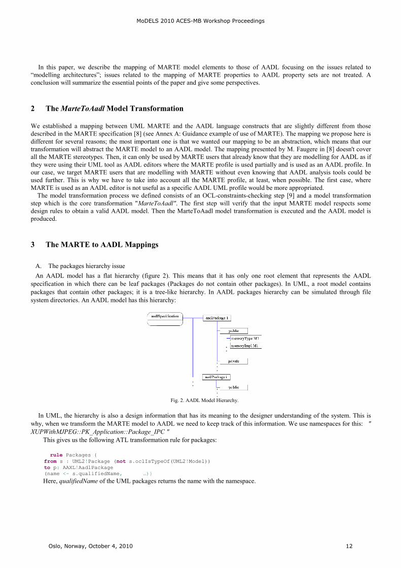
An AADL model has a flat hierarchy (figure 2). This means that it has only one root element that represents the AADL
specification in which there can be leaf packages (Packages do not contain other packages). In UML, a root model contains
packages that contain other packages; it is a tree-like hierarchy. In AADL packages hierarchy can be simulated through file
system directories. An AADL model has this hierarchy:
Fig. 2. AADL Model Hierarchy.
In UML, the hierarchy is also a design information that has its meaning to the designer understanding of the system. This is
why, when we transform the MARTE model to AADL we need to keep track of this information. We use namespaces for this: "
XUPWithMJPEG::PK_Application::Package_IPC "
This gives us the following ATL transformation rule for packages:
rule Packages {
from s : UML2!Package (not s.oclIsTypeOf(UML2!Model))
to p: AAXL!AadlPackage
(name <- s.qualifiedName, …)}
Here, qualified#ame of the UML packages returns the name with the namespace.
MoDELS 2010 ACES-MB Workshop Proceedings
Oslo, Norway, October 4, 2010 12

B. Mapping UML Class diagram hierarchy to AADL Category Types and implementations hierarchy
In a first approach we used the isAbstract Boolean field of UML classes to differentiate between an AADL type and an
AADL implementation; this was a solution to avoid using additional stereotypes. But we finally decided to create an AADL type
and an AADL implementation for each UML class because the first approach was like using MARTE as an AADL editor. With
the first approach we had to add many OCL constraints to verify we did not have semantically illegal AADL configurations. For
example, an abstract class that inherits from a non-abstract one would lead to an AADL type extending an AADL implementation
which is illegal in AADL. We also had to choose which UML relationships would be mapped to the AADL implementation
relationship and which one would be mapped to the AADL extension relationship. We distinguished three cases of UML
configurations (figure 3) that can be seen as an AADL equivalent to:
Fig. 3. Possible AADL type implementations with UML (Name with Italics = isAbstract)
We noticed that we couldn't use an interface to depict an AADL Type because a UML interface is not an
encapsulatedClassifier (cannot have ports). In fact, we can only use classes to define ports, which is an important aspect in
architecture modelling.
We could use the realization to depict an AADL type but in the composite diagram, in an implementation element we would
not be able to inherit the ports declared in the corresponding class, we could only do that with the inheritance, in addition to this,
we thought we would reserve this notation to the bus/data access AADL construct. This is why only the second case (figure 3)
was possible.
We also had to prevent someone from using a generalization between two classes that do not correspond to the same
category (processor, bus, thread…). This was the role of the pre-transformation verification step which induced more OCL
constraints.
We also mapped the use of a generalization between two abstract classes from the same component category or between two
non-abstract classes from the same component category to the extension mechanism in AADL.
Fig. 4. Four combinations of generalizations could be found in UML.
Four possibilities can be drawn using generalizations in UML (figure 4). Each possibility corresponded to a different AADL
construct:
• The first one mapped to the AADL implementation
• The second becomes meaningless in AADL.
• The third and fourth situations mapped to the AADL extension construct.
This first choice led us to a complicated mapping that, as we already said, was using MARTE as an AADL editor. It also
generated too much OCL constraints that impacted dramatically the designing activity as the designer had to know all these
imposed rules in addition to the design language. We finally chose a different mapping that is much easier for the designer, who
doesn't need to know more design rules than those of UML and MARTE. This mapping consists on splitting each class into a type
and its implementation and to map the UML generalization to the "extends" mechanism of AADL as shown in the following table
1 (here the "extends" AADL mechanism is depicted with the black-headed arrow with discontinuous arc, the blue-headed arrow
in AADL depicts the "implements" AADL mechanism).
The following example (figure 5) illustrates how this mapping can translate any UML/MARTE configuration to AADL with
only one assumption on the initial MARTE model.
MoDELS 2010 ACES-MB Workshop Proceedings
Oslo, Norway, October 4, 2010 13

TABLE 1
MAPPING UML CLASSES AND GENERALIZATIONS TO AADL
Fig. 5. UML class diagram translation. (ClassB and ClassD are abstract)
With this mapping we will never have extensions between implementations, which is not a problem as long as both
representations are equivalent. This mapping also guarantees that each UML generalization's hierarchy can be transformed to an
equivalent extension's hierarchy in AADL.
C. Mapping MARTE constructs to AADL component categories
MARTE offers more detailed design possibilities than AADL. In fact, all AADL constructs have their mapping inside
MARTE but the other way is not true. For example, in MARTE we have a HwProcessor and a HwComputingResource. Both of
them can be translated in an AADL processor but the design detail in AADL will be of coarser granularity. Another example is
the HwBridge in MARTE that has no equivalent in AADL. It must therefore be abstracted in AADL to a general device that
corresponds in MARTE to HwDevice.
As we already said, we tried to make this mapping an abstraction of MARTE to AADL. This is why we mapped each AADL
component category to a set of MARTE model elements.
MoDELS 2010 ACES-MB Workshop Proceedings
Oslo, Norway, October 4, 2010 14
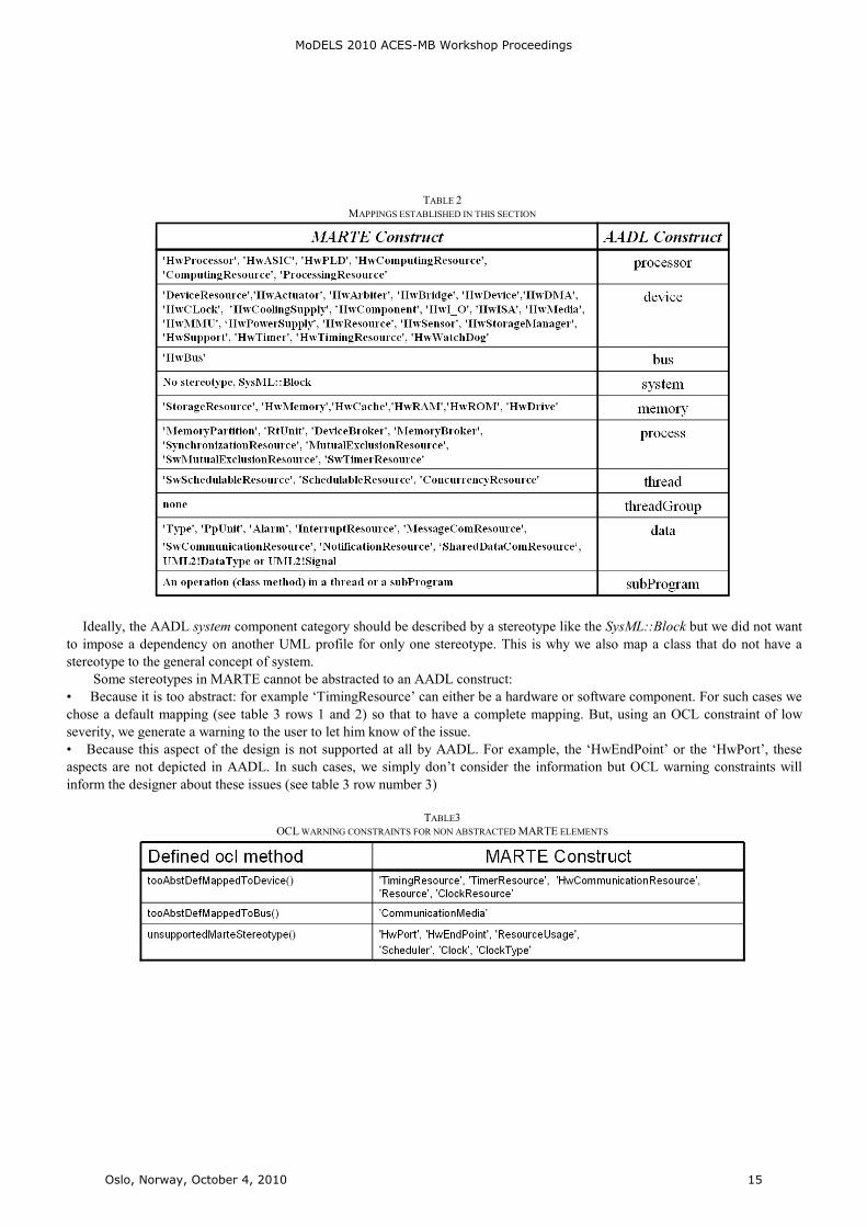
TABLE 2
MAPPINGS ESTABLISHED IN THIS SECTION
Ideally, the AADL system component category should be described by a stereotype like the SysML::Block but we did not want
to impose a dependency on another UML profile for only one stereotype. This is why we also map a class that do not have a
stereotype to the general concept of system.
Some stereotypes in MARTE cannot be abstracted to an AADL construct:
• Because it is too abstract: for example ‘TimingResource’ can either be a hardware or software component. For such cases we
chose a default mapping (see table 3 rows 1 and 2) so that to have a complete mapping. But, using an OCL constraint of low
severity, we generate a warning to the user to let him know of the issue.
• Because this aspect of the design is not supported at all by AADL. For example, the ‘HwEndPoint’ or the ‘HwPort’, these
aspects are not depicted in AADL. In such cases, we simply don’t consider the information but OCL warning constraints will
inform the designer about these issues (see table 3 row number 3)
TABLE3
OCL WARNING CONSTRAINTS FOR NON ABSTRACTED MARTE ELEMENTS
MoDELS 2010 ACES-MB Workshop Proceedings
Oslo, Norway, October 4, 2010 15
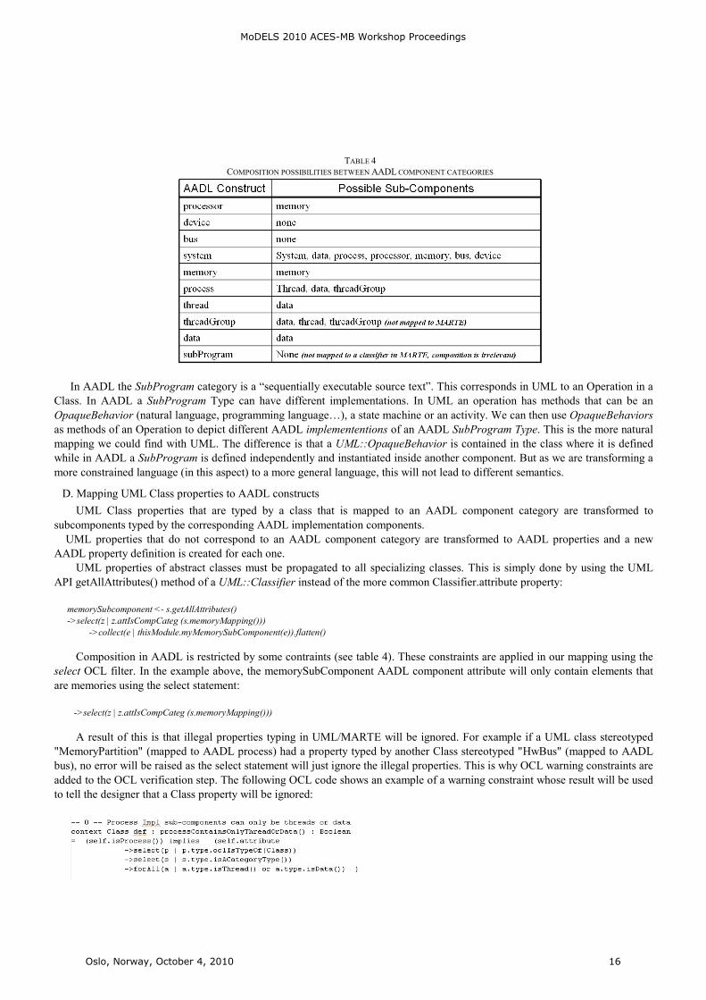
TABLE 4
COMPOSITION POSSIBILITIES BETWEEN AADL COMPONENT CATEGORIES
In AADL the SubProgram category is a “sequentially executable source text”. This corresponds in UML to an Operation in a
Class. In AADL a SubProgram Type can have different implementations. In UML an operation has methods that can be an
OpaqueBehavior (natural language, programming language…), a state machine or an activity. We can then use OpaqueBehaviors
as methods of an Operation to depict different AADL implemententions of an AADL SubProgram Type. This is the more natural
mapping we could find with UML. The difference is that a UML::OpaqueBehavior is contained in the class where it is defined
while in AADL a SubProgram is defined independently and instantiated inside another component. But as we are transforming a
more constrained language (in this aspect) to a more general language, this will not lead to different semantics.
D. Mapping UML Class properties to AADL constructs
UML Class properties that are typed by a class that is mapped to an AADL component category are transformed to
subcomponents typed by the corresponding AADL implementation components.
UML properties that do not correspond to an AADL component category are transformed to AADL properties and a new
AADL property definition is created for each one.
UML properties of abstract classes must be propagated to all specializing classes. This is simply done by using the UML
API getAllAttributes() method of a UML::Classifier instead of the more common Classifier.attribute property:
memorySubcomponent <- s.getAllAttributes()
->select(z | z.attIsCompCateg (s.memoryMapping()))
->collect(e | thisModule.myMemorySubComponent(e)).flatten()
Composition in AADL is restricted by some contraints (see table 4). These constraints are applied in our mapping using the
select OCL filter. In the example above, the memorySubComponent AADL component attribute will only contain elements that
are memories using the select statement:
->select(z | z.attIsCompCateg (s.memoryMapping()))
A result of this is that illegal properties typing in UML/MARTE will be ignored. For example if a UML class stereotyped
"MemoryPartition" (mapped to AADL process) had a property typed by another Class stereotyped "HwBus" (mapped to AADL
bus), no error will be raised as the select statement will just ignore the illegal properties. This is why OCL warning constraints are
added to the OCL verification step. The following OCL code shows an example of a warning constraint whose result will be used
to tell the designer that a Class property will be ignored:
MoDELS 2010 ACES-MB Workshop Proceedings
Oslo, Norway, October 4, 2010 16
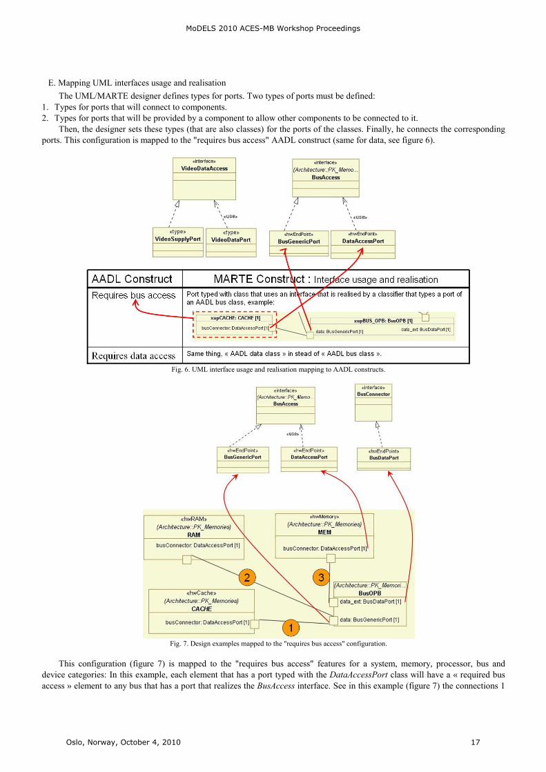
E. Mapping UML interfaces usage and realisation
The UML/MARTE designer defines types for ports. Two types of ports must be defined:
1. Types for ports that will connect to components.
2. Types for ports that will be provided by a component to allow other components to be connected to it.
Then, the designer sets these types (that are also classes) for the ports of the classes. Finally, he connects the corresponding
ports. This configuration is mapped to the "requires bus access" AADL construct (same for data, see figure 6).
Fig. 6. UML interface usage and realisation mapping to AADL constructs.
Fig. 7. Design examples mapped to the "requires bus access" configuration.
This configuration (figure 7) is mapped to the "requires bus access" features for a system, memory, processor, bus and
device categories: In this example, each element that has a port typed with the DataAccessPort class will have a « required bus
access » element to any bus that has a port that realizes the BusAccess interface. See in this example (figure 7) the connections 1
MoDELS 2010 ACES-MB Workshop Proceedings
Oslo, Norway, October 4, 2010 17
and 2 where both busConnector ports are typed by DataAccessPort which uses the BusAccess interface that is realized by the
BusGenericPort class that types the data port in the BusOPB class.
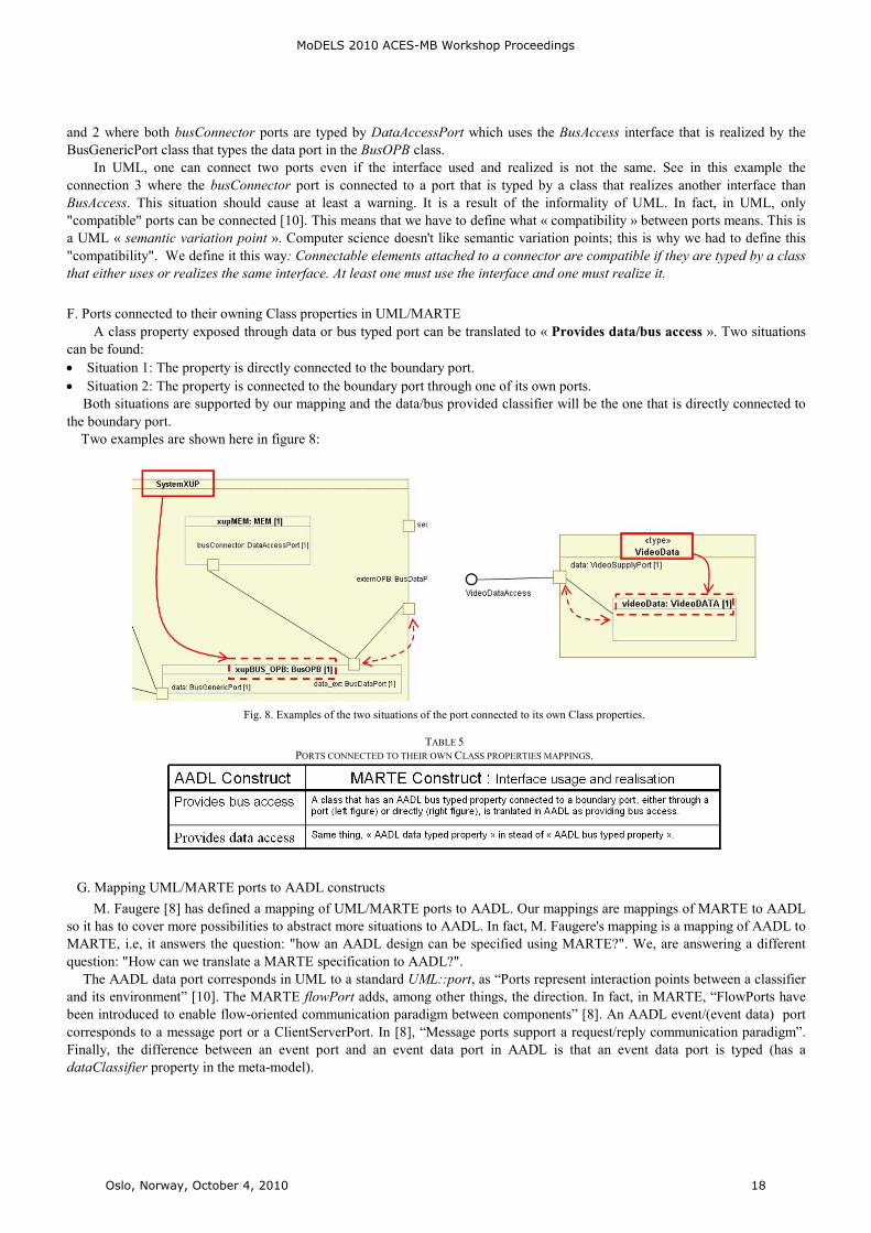
In UML, one can connect two ports even if the interface used and realized is not the same. See in this example the
connection 3 where the busConnector port is connected to a port that is typed by a class that realizes another interface than
BusAccess. This situation should cause at least a warning. It is a result of the informality of UML. In fact, in UML, only
"compatible" ports can be connected [10]. This means that we have to define what « compatibility » between ports means. This is
a UML « semantic variation point ». Computer science doesn't like semantic variation points; this is why we had to define this
"compatibility". We define it this way: Connectable elements attached to a connector are compatible if they are typed by a class
that either uses or realizes the same interface. At least one must use the interface and one must realize it.
F. Ports connected to their owning Class properties in UML/MARTE
A class property exposed through data or bus typed port can be translated to « Provides data/bus access ». Two situations
can be found:
• Situation 1: The property is directly connected to the boundary port.
• Situation 2: The property is connected to the boundary port through one of its own ports.
Both situations are supported by our mapping and the data/bus provided classifier will be the one that is directly connected to
the boundary port.
Two examples are shown here in figure 8:
Fig. 8. Examples of the two situations of the port connected to its own Class properties.
TABLE 5
PORTS CONNECTED TO THEIR OWN CLASS PROPERTIES MAPPINGS.
G. Mapping UML/MARTE ports to AADL constructs
M. Faugere [8] has defined a mapping of UML/MARTE ports to AADL. Our mappings are mappings of MARTE to AADL
so it has to cover more possibilities to abstract more situations to AADL. In fact, M. Faugere's mapping is a mapping of AADL to
MARTE, i.e, it answers the question: "how an AADL design can be specified using MARTE?". We, are answering a different
question: "How can we translate a MARTE specification to AADL?".
The AADL data port corresponds in UML to a standard UML::port, as “Ports represent interaction points between a classifier
and its environment” [10]. The MARTE flowPort adds, among other things, the direction. In fact, in MARTE, “FlowPorts have
been introduced to enable flow-oriented communication paradigm between components” [8]. An AADL event/(event data) port
corresponds to a message port or a ClientServerPort. In [8], “Message ports support a request/reply communication paradigm”.
Finally, the difference between an event port and an event data port in AADL is that an event data port is typed (has a
dataClassifier property in the meta-model).
MoDELS 2010 ACES-MB Workshop Proceedings
Oslo, Norway, October 4, 2010 18
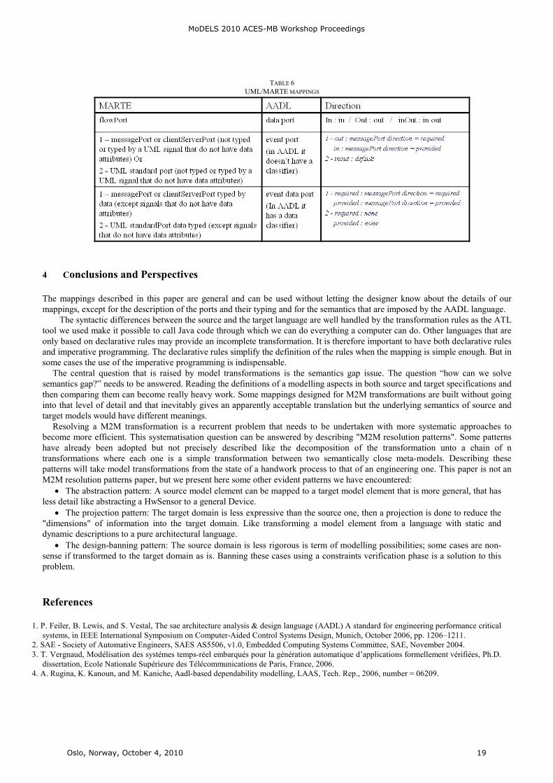
TABLE 6
UML/MARTE MAPPINGS
4 Conclusions and Perspectives
The mappings described in this paper are general and can be used without letting the designer know about the details of our
mappings, except for the description of the ports and their typing and for the semantics that are imposed by the AADL language.
The syntactic differences between the source and the target language are well handled by the transformation rules as the ATL
tool we used make it possible to call Java code through which we can do everything a computer can do. Other languages that are
only based on declarative rules may provide an incomplete transformation. It is therefore important to have both declarative rules
and imperative programming. The declarative rules simplify the definition of the rules when the mapping is simple enough. But in
some cases the use of the imperative programming is indispensable.
The central question that is raised by model transformations is the semantics gap issue. The question “how can we solve
semantics gap?” needs to be answered. Reading the definitions of a modelling aspects in both source and target specifications and
then comparing them can become really heavy work. Some mappings designed for M2M transformations are built without going
into that level of detail and that inevitably gives an apparently acceptable translation but the underlying semantics of source and
target models would have different meanings.
Resolving a M2M transformation is a recurrent problem that needs to be undertaken with more systematic approaches to
become more efficient. This systematisation question can be answered by describing "M2M resolution patterns". Some patterns
have already been adopted but not precisely described like the decomposition of the transformation unto a chain of n
transformations where each one is a simple transformation between two semantically close meta-models. Describing these
patterns will take model transformations from the state of a handwork process to that of an engineering one. This paper is not an
M2M resolution patterns paper, but we present here some other evident patterns we have encountered:
• The abstraction pattern: A source model element can be mapped to a target model element that is more general, that has
less detail like abstracting a HwSensor to a general Device.
• The projection pattern: The target domain is less expressive than the source one, then a projection is done to reduce the
"dimensions" of information into the target domain. Like transforming a model element from a language with static and
dynamic descriptions to a pure architectural language.
• The design-banning pattern: The source domain is less rigorous is term of modelling possibilities; some cases are non-
sense if transformed to the target domain as is. Banning these cases using a constraints verification phase is a solution to this
problem.
References
1. P. Feiler, B. Lewis, and S. Vestal, The sae architecture analysis & design language (AADL) A standard for engineering performance critical
systems, in IEEE International Symposium on Computer-Aided Control Systems Design, Munich, October 2006, pp. 1206–1211.
2. SAE - Society of Automative Engineers, SAES AS5506, v1.0, Embedded Computing Systems Committee, SAE, November 2004.
3. T. Vergnaud, Modélisation des systémes temps-réel embarqués pour la génération automatique d’applications formellement vérifiées, Ph.D.
dissertation, Ecole Nationale Supérieure des Télécommunications de Paris, France, 2006.
4. A. Rugina, K. Kanoun, and M. Kaniche, Aadl-based dependability modelling, LAAS, Tech. Rep., 2006, number = 06209.
MoDELS 2010 ACES-MB Workshop Proceedings
Oslo, Norway, October 4, 2010 19

5. J. Hugues, B. Zalila, and L. Pautet, Rapid prototyping of distributed real-time embedded systems using the aadl and ocarina, in Proceedings
of the 18th IEEE International Workshop on Rapid System Prototyping (RSP’07). IEEE Computer Society Press, may 2007, pp. 106–112,
porto Alegre, Brazil.
6. The SPICES ITEA Project Website. [Online]. Available: http://www.spices-itea.org/
7. OSATE homepage, http://www.aadl.info/aadl/currentsite/tool/osate-down.html.
8. A UML Profile for MARTE: Modeling and Analysis of Real-Time Embedded systems Beta 2, OMG Adopted Specification, OMG
Document Number: ptc/2008-06-09, http://www.omgmarte.org/Documents/Specifications/08-06-09.pdf.
9. S. Turki et Al, Checking syntactic constraints on models using ATL model transformations, Workshop mtATL2009 Nantes, 08-09 july
2009.
10. UML 2.2 OMG official specification, UML superstructure specification, 2009/02/02, www.omg.org/spec/UML/2.2/Superstructure/PDF/
MoDELS 2010 ACES-MB Workshop Proceedings
Oslo, Norway, October 4, 2010 20
A Time-Centric Model for Cyber-Physical Applications
John C. Eidson, Edward A. Lee, Slobodan Matic, Sanjit A. Seshia, and Jia Zou
University of California at Berkeley, Berkeley, CA, 94720, USA{eidson,eal,matic,sseshia,jiazou}@eecs.berkeley.edu
Abstract. The problem addressed by this paper is that real-time embedded soft-ware today is commonly built using programming abstractions with little or notemporal semantics. The paper discusses the use of an extension to the PtolemyII framework as a coordination language for the design of distributed real-timeembedded systems. Specifically, the paper shows how to use modal models in thecontext of the PTIDES extension of Ptolemy II to provide a firm basis for thedesign of an important class of problems. We show the use of this environment inthe design of interesting practical real-time systems.
1 IntroductionIn cyber-physical systems (CPS) the passage of time becomes a central feature — infact, it is this key constraint that distinguishes these systems from distributed comput-ing in general. Time is central to predicting, measuring, and controlling properties ofthe physical world: given a physical model, the initial state, the inputs, and the amountof time elapsed, one can compute the current state of the plant. This principle pro-vides the foundations of control theory. However, for current mainstream programmingparadigms, given the source code, the program’s initial state, and the amount of timeelapsed, we cannot reliably predict future program state. When that program is inte-grated into a system with physical dynamics, this makes principled design of the entiresystem difficult. Moreover, the disparity between the dynamics of the physical plant andthe program potentially leads to errors, some of which can be catastrophic.
The challenge of integrating computing and physical processes has been recognizedfor some time, motivating the emergence of hybrid systems theories. Progress in thatarea, however, remains limited to relatively simple systems combining ordinary differ-ential equations with automata. These models inherit from control theory a uniform no-tion of time, an oracle called t available simultaneously in all parts of the system. Evenadaptations of traditional computer science concepts to distributed control problemsmake the assumption of the oracle t. For example, in [21] consensus problems fromcomputer science are translated into control systems formulations. These formulations,however, break down without the uniform notion of time that governs the dynamics. Innetworked software implementations, such a uniform notion of time cannot be preciselyrealized. Time triggered networks [12] can be used to approximate a uniform model oftime, but the analysis of the dynamics has to include the imperfections.
Although real-time software is not a new problem there exist trends with a potentialto change the landscape. Model-based design [11], for example, has caught on in in-dustrial practice, through the use of tools such as Simulink, TargetLink, and LabVIEW.Domain-specific modeling languages are increasingly being used because they tend tohave formal semantics that experts can use to describe their domain constraints. This
MoDELS 2010 ACES-MB Workshop Proceedings
Oslo, Norway, October 4, 2010 21
enables safety or quality of service verification, and thus helps with integration andscalability of designed systems. For CPS, models with temporal semantics are particu-larly natural to system designers. An example of such a language is Timing-AugmentedDescription Language [10], a domain-specific language recently developed within theautomotive initiative AUTOSAR. However, the multiplication of modeling languagesraises the question of mutual consistency and interoperability. This is mainly why theOMG consortium extended UML with a profile called MARTE (Modeling and Anal-ysis of Real-Time and Embedded Systems) [23]. Another trend is the acceptance ofsynchronous-reactive languages, particularly SCADE [1], in safety critical applications.The model-based design approach we propose in this paper borrows sound fixed-pointsemantics from the synchronous languages, but is more flexible and concurrent. Alsorelated to our work are component frameworks based on formal verification methods,like the BIP framework [2], but they mostly focus on compositional verification of prop-erties such as deadlock freedom. BIP relies on priorities to model scheduling policiesand, as far as we know, has not been used to address modeling and design problems forcomponents with explicit timing requirements.
To ensure proper real-time interaction between the dynamics of the controller andthe dynamics of the controlled physical system, programmers of embedded systemstypically use platform-specific system timers. However, design of the system should beindependent of implementation details, in order to allow for portability of the design.In [26] we presented a programming model called PTIDES (programming temporally-integrated distributed embedded systems) that addresses this problem by relying on asuitable abstraction of time. With PTIDES, application programmers specify the inter-action between the control program and the physical dynamics in the system model,without the knowledge of details such as timers. Paper [28] studies the semantic prop-erties of an execution model that permits out of order processing of events withoutsacrificing determinacy and without requiring backtracking.
The goal of this work is to demonstrate the usefulness of PTIDES for time-criticalCPS applications. We first explain how design with PTIDES results in deterministicprocessing of events. Then we illustrate how to specify timed reactions to events inPTIDES models. This results in traces from model simulation and execution of auto-matically generated code being identical. In order to account for different modes ofoperation, modal models have been widely used in embedded system design [8]. Here,we show the use of modal models within the context of a timed environment, i.e., weillustrate timed mode transitions and operations in modes at certain time instants.
This paper is organized as follows. First, section 2 discusses the PTIDES designenvironment, which enables a programmer to first model and simulate the design, andthen implement it through a target-specific code generator. At the top level, this envi-ronment uses the PTIDES [26] extension to the Ptolemy II simulation framework [7] asa coordination language for the design of distributed real-time embedded systems. Sec-tion 3 then explains temporal semantics of PTIDES, and shows how the use of modalmodels in the context of PTIDES provides a firm basis for the design of an importantclass of CPS. This is followed by a detailed example in section 4, which shows the useof this environment and particularly the ability to explicitly address timing in the designof interesting practical real-time systems. We conclude in section 5.
MoDELS 2010 ACES-MB Workshop Proceedings
Oslo, Norway, October 4, 2010 22
2 Design Environment
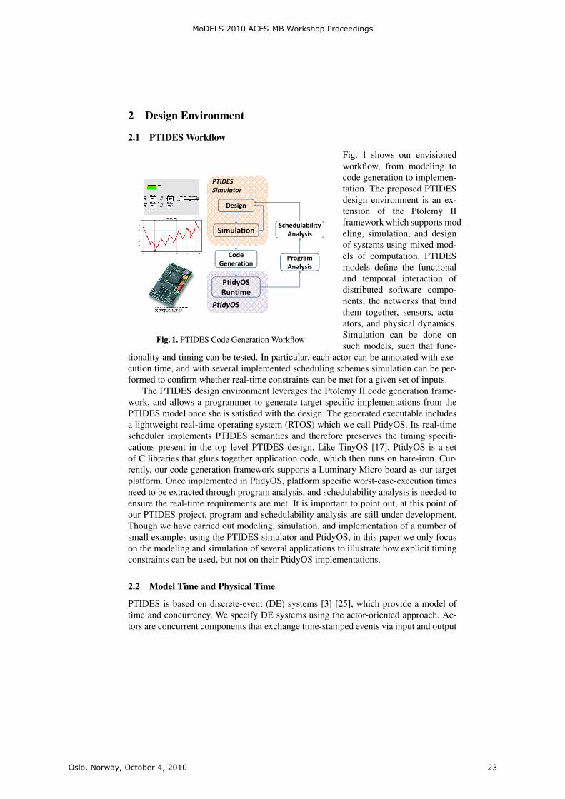
2.1 PTIDES Workflow
PTIDES Simulator
Design
SimulationSchedulability
Analysis
Code P
Analysis
Code Generation
Program Analysis
PtidyOSRuntime
PtidyOS
Fig. 1. PTIDES Code Generation Workflow
Fig. 1 shows our envisionedworkflow, from modeling tocode generation to implemen-tation. The proposed PTIDESdesign environment is an ex-tension of the Ptolemy IIframework which supports mod-eling, simulation, and designof systems using mixed mod-els of computation. PTIDESmodels define the functionaland temporal interaction ofdistributed software compo-nents, the networks that bindthem together, sensors, actu-ators, and physical dynamics.Simulation can be done onsuch models, such that func-
tionality and timing can be tested. In particular, each actor can be annotated with exe-cution time, and with several implemented scheduling schemes simulation can be per-formed to confirm whether real-time constraints can be met for a given set of inputs.
The PTIDES design environment leverages the Ptolemy II code generation frame-work, and allows a programmer to generate target-specific implementations from thePTIDES model once she is satisfied with the design. The generated executable includesa lightweight real-time operating system (RTOS) which we call PtidyOS. Its real-timescheduler implements PTIDES semantics and therefore preserves the timing specifi-cations present in the top level PTIDES design. Like TinyOS [17], PtidyOS is a setof C libraries that glues together application code, which then runs on bare-iron. Cur-rently, our code generation framework supports a Luminary Micro board as our targetplatform. Once implemented in PtidyOS, platform specific worst-case-execution timesneed to be extracted through program analysis, and schedulability analysis is needed toensure the real-time requirements are met. It is important to point out, at this point ofour PTIDES project, program and schedulability analysis are still under development.Though we have carried out modeling, simulation, and implementation of a number ofsmall examples using the PTIDES simulator and PtidyOS, in this paper we only focuson the modeling and simulation of several applications to illustrate how explicit timingconstraints can be used, but not on their PtidyOS implementations.
2.2 Model Time and Physical Time
PTIDES is based on discrete-event (DE) systems [3] [25], which provide a model oftime and concurrency. We specify DE systems using the actor-oriented approach. Ac-tors are concurrent components that exchange time-stamped events via input and output
MoDELS 2010 ACES-MB Workshop Proceedings
Oslo, Norway, October 4, 2010 23

ports. The time in time stamps is a part of the model, playing a formal role in the com-putation. We refer to this time as model time. It may or may not bear any relationshipto time in the physical world, which in this paper we will call physical time. In basicDE semantics, each actor processes input events in time-stamp order. There are no con-straints on the physical time at which events are processed. We assume a variant of DEthat has been shown to integrate well with models of continuous dynamics [16]. Thepurpose of this paper is not to study its rigorous and determinate semantics. For that aninterested reader is referred to [18] and [13].
PTIDES extends DE by establishing a relationship between model time and physi-cal time at sensors, actuators, and network interfaces. Whereas DE models have tradi-tionally been used to construct simulations, PTIDES provides a programmer’s modelfor the specification of both functional and temporal properties of deployable cyber-physical systems. There are three key constraints that define the relationship betweenmodel time and physical time: 1) sensors produce events with timetamp τ at physicaltime t ≥ τ , 2) actuators receives events with timestamp τ at physical time t ≤ τ , and 3)network interfaces receive events with timestamp τ at physical time t ≤ τ . We explainthese constraints in detail below.
Fig. 2. Prototypical CPS
The basic PTIDESmodel is explainedby referring to Fig-ure 2, which showsthree computationalplatforms (typicallyembedded computers)connected by a net-work and having lo-cal sensors and actu-ators. On Platform 3,a component labeledLocal Event Sourceproduces a sequenceof events that drivean actuator through
two other components. The component labeled Computation4 processes each event andproduces an output event with the same time stamp as the input event that triggers thecomputation. Those events are merged in time stamp order by a component Merge anddelivered to a component labeled Actuator1.
In PTIDES, an actuator component interprets its input events as commands to per-form some physical action at a physical time equal to the time stamp of the event. Thephysical time of this event is measured based on clocks commensurate with UTC or alocal system-wide real-time clock. This interpretation imposes our first real-time con-straint on all the software components upstream of the actuator. Each event must bedelivered to the actuator at a physical time earlier than the event’s time stamp to avoidcausality violations. Either PtidyOS or the design of the actuator itself ensures that theactuation affects the physical world at a time equal to the event time stamp. Thereforethe deployed system exhibits the exact temporal behavior specified in the design to
MoDELS 2010 ACES-MB Workshop Proceedings
Oslo, Norway, October 4, 2010 24
within the limits of the accuracy of clock synchronization between platforms and thetemporal resolution of the actuators and clocks.
In Figure 2, Platform 3 contains an actuator that is affected both by some localcontrol and by messages received over the network. The local control commands aregenerated by the actor Local Event Source, and modified by the component Computa-tion4. The Merge component can inject commands to the actuator that originate fromeither the local event source or from the network. The commands are merged in order oftheir time stamps. Notice that the top input to the Merge component comes from com-ponents that get inputs from sensors on the remote platforms. The sensor componentsproduce on their output ports time-stamped events. Here, the PTIDES model imposes asecond relationship between model time stamps and physical time. Specifically, when asensor component produces a time-stamped output event, that time stamp must be lessthan or equal to physical time, however physical time is measured. The sensor can onlytell the system about the past, not about the future.
The third and final relationship refers to network interfaces. In this work we assumethat the act of sending an event via a network is similar to delivering an event to anactuator; i.e., the event must be delivered to the network interface by a deadline equalto the time stamp of the event. Consider Platform 1 in Figure 2 as an example. Whenan event of time stamp τ is to be sent into the network fabric, the transmission of thisevent needs to happen no later than physical time τ . In general, we could set the dead-line to something other than the time stamp, but for our purposes here, it is sufficientthat there be a deadline, and that the deadline be a known function of the time stamp.Our assumption that it equals the time stamp makes the analysis in next subsectionsparticularly simple, so for the purposes of this paper we proceed with that.
2.3 Event Processing in PTIDES
Under benign conditions [13], DE models are determinate in that given the time-stampedinputs to the model, all events are fully defined. Thus, any correct execution of themodel must deliver the same time-stamped events to actuators, given the same time-stamped events from the sensors (this assumes that each software component is itselfdeterminate). An execution of a PTIDES model is required to follow DE semantics,and hence deliver this determinacy. It is this property that makes executions of PTIDESmodels repeatable. A test of any “correct” execution of a PTIDES model will matchthe behavior of any other correct execution.
The key question is how to deliver a “correct” execution. For example, consider theMerge component in Figure 2. This component must merge events in time-stamp orderfor delivery to the actuator. Given an event from the local Computation4 component,when can it safely pass that event to the actuator? Here lies a key feature of PTIDES.The decision to pass the event to the actuator is made locally at run time by comparingthe time stamp of the event against a local clock that is tracking physical time. Thisstrategy results in decentralized control, removing the risks introduced by a single pointof failure, and making systems much more modular and composable.
There are two key assumptions made in PTIDES. First, distributed platforms havereal-time clocks synchronized with bounded error. The PTIDES model of computationworks with any bound on the error, but the smaller the bound, the tighter the real-time
MoDELS 2010 ACES-MB Workshop Proceedings
Oslo, Norway, October 4, 2010 25
constraints can be. Time synchronization techniques such as IEEE 1588 [9] can deliverreal-time clock precision on the nanosecond order.
Second, PTIDES requires that there be a bound on the communication delay be-tween any two hardware components. Specifically, sensors and actuators must delivertime-stamped events to the run-time system within a bounded delay, and a networkmust transport a time-stamped event with a bounded delay. Bounding network delayis potentially more problematic when using generic networking technologies such asEthernet, but bounded network delay is already required today in the applications of in-terest here. This has in fact historically forced deployments of these applications to usespecialized networking techniques (such as time-triggered architectures [12], FlexRay[19], and CAN buses [24]). One of the goals of our research is to use PTIDES on lessconstraining networking architectures, e.g. to allow more flexibility in processing aperi-odic events. In the time-triggered architectures, all actions are initiated by the computersystem at known time instants. In our approach, events coming from the environmentare allowed and are treated deterministically. Here it is sufficient to observe that theseboundedness assumptions are achievable in practice. Since PTIDES allows detection ofrun-time timing errors, it is possible to model responses to failures of these assumptions.
Once these two assumptions (bounded time synchronization error and communica-tion delays) are accepted, together with deadlines for network interfaces and actuators,local decisions can be made to deliver events in Figure 2 without compromising DEsemantics. Specifically, in Figure 2, notice that the top input to the Merge comes fromSensor1 and Sensor2 through a chain of software components and a network link. Staticanalysis of these chains reveals the operations performed on time stamps. In particular,in this figure, assume that the only components that manipulate time stamps are thecomponents labeled model time delay di. These components accept an input event andproduce an output event with the same data but with a time stamp incremented by di.
Assume we have an event ewith time stamp τ at the bottom input of Merge, and thatthere is no other event on Platform 3 with an earlier time stamp. This event can be passedto the output only when we are sure that no event will later appear at the top input ofMerge with a time stamp less than or equal to τ . This will preserve DE semantics. Whencan we be sure that e is safe to process in this way? We assume that events destined tothe top input of Merge must be produced by a reaction in Computation3 to events thatarrive over the network. Moreover, the outputs of Computation3 are further processedto increment their time stamps by d2. Thus, we are sure e is safe to process when noevents from the network will arrive at Platform 3 with time stamps less than or equal toτ − d2. When can we be sure of this? Let us assume a network delay bound of n anda clock synchronization error bound of s between platforms. By the network interfaceassumption discussed above, we know that all events sent by Platform 1 or Platform 2with time stamps less than τ − d2 will be sent over the network by the physical timeτ − d2. Consequently, all events with time stamp less than or equal to τ − d2 will bereceived on Platform3 by the physical time τ − d2 + n+ s, where the s term accountsfor the possible disagreement in the measurement of physical time. Thus when physicaltime on Platform 3 exceeds τ−d2+n+s, event ewill be safe to process. In other words,to ensure that the processing of an event obeys DE semantics, at run time, the only testthat is needed is to compare time stamps to physical time with an offset (in the previousexample, the offset is−d2+n+s). Notice, if we assume the model is static (components
MoDELS 2010 ACES-MB Workshop Proceedings
Oslo, Norway, October 4, 2010 26

are not added during runtime and connections are not changed); minimum bounds onmodel time delays (di’s) for components are known statically; and the upper boundsfor sensor processing times, network delays, and network synchronization errors areknown, then the offsets can be calculated statically using a graph traversal algorithm.
Note that the distributed execution control of PTIDES introduces another valuableform of robustness in the system. For example, in Figure 2, if, say, Platform 1 ceasesfunctioning altogether, and stops sending events on the network, that fact alone cannotprevent Platform 3 from continuing to drive its actuator with locally generated controlsignals. This would not be true if we preserved DE semantics by conservative tech-niques based on the work by Chandy and Misra [4]. It is also easy to see that PTIDESmodels can include components that monitor system integrity. For example, Platform3 could raise an alarm and change operating modes if it fails to get messages fromPlatform 1. It could also raise an alarm if it later receives a message with an unexpect-edly small time stamp. Time synchronization with bounded error helps to give suchmechanisms a rigorous semantics.
As long as events are delivered on time and in time-stamp order to actuators, theexecution will look exactly the same to the environment. This makes PTIDES modelsmuch more robust than typical real-time software, because small changes in the (phys-ical) execution timing of internal events are not visible to the environment (as long asreal-time constraints are met at sensors, actuators and network interfaces). Moreover,since execution of a PTIDES model carries time stamps at run time, run time violationsof deadlines at actuators can be detected. PTIDES models can be easily made adaptive,changing modes of operation, for example, when such real-time violations occur. Ingeneral, therefore, PTIDES models provide adequate runtime information for detectingand reacting to a rich variety of timing faults.
3 Temporal Semantics in PTIDES
PTIDES semantics is fully described in [26] and [28], and is based on a tagged-signalmodel [15]. For this discussion the important point is that actors define a functionalrelationship between a set of tagged signals on the input ports and a set of tagged signalson the output ports of the actor, Fa : SI → SO. Here, I is a set of input ports, O is aset of output ports, and S a set of signals. The signals s ∈ S are sets of (time stamp,value) pairs of the form (τ, v) ∈ T ×V where the time set T represents time and V is aset of values (the data payloads) of events. For simulation, the most common use of DEmodeling, time stamps typically have no connection with real time, and can advanceslower or faster than real time [25].
Fig. 3. Linear combination of actors
Actors are permittedto modify the time stampand most commonly willmodify the model timemember, i.e. the timestamp, to indicate thepassage of model time.For example, a delay ac-tor has one input port and
MoDELS 2010 ACES-MB Workshop Proceedings
Oslo, Norway, October 4, 2010 27

one output port and its behavior is given by Fδ(s) : S → S where for each s ∈ S wehave Fδ(s) = {(t+ δ, v) | (t, v) ∈ s}. That is, the output events are identical to inputevents except that the model time is increased by δ, a parameter of the actor.
Consider the simple sensor, actor, actuator system of Figure 3. In this example weassume Fa(s) = {(t, 2 ∗ v) | (t, v) ∈ s}; i.e., the output is the same as the input but withits value scaled by a factor of 2. Both variants (a) and (b) of this figure show a serialcombination of a sensor, delay, scaling, and actuator actors. The sensor actors producean event (25 seconds, 15 volts) where the time stamp 25 seconds is the physical timeat the time of sensing. The delay actor increments the model time by 10 and the scaleactor doubles the value from 15 volts to 30 volts. In both cases the actuator receivesan event (35 seconds, 30 volts), which it interprets as a command to the actuator toinstantiate the value 30 volts at a physical time of 35 seconds. As long as deadlinesat the actuators are met, all observable effects with models (a) and (b) are identical,regardless of computation times and scheduling decisions.
Modal Models.
Fig. 4. General pattern of a modal model with two modes,each with its own refinement
The use of modal modelsis well established both in theliterature, for example Stat-echarts [8], UML [22], andin commercial products suchas Simulink/Stateflow fromMathWorks [20]. Note thatwe use the term modal todescribe models that extendfinite-state machines by al-lowing states to have PtolemyII models as refinements [14].The time-centric modal mod-els discussed here are particu-larly useful for the specifica-tion of modes of operation ina CPS as we explain in section4. Our style for modal modelsfollows the pattern shown in Figure 4. A modal model is an actor, shown in the figurewith two input ports and one output port. Inside the actor is a finite state machine (FSM),shown in the figure with two states, labeled mode1 and mode2. The transitions betweenstates have guards and actions, and each state has a refinement that is a submodel. Themeaning of such a modal model is that the input-output behavior of the ModalModelactor is given by the input-output behavior of the refinement of the current state.
Modal models introduce additional temporal considerations into a design. This isespecially true for modal models that modify the time stamp of a signal. While thePtolemy II environment provides several modal model execution options such as a pre-emptive evaluation of guards prior to execution of a state refinement, the principal fea-tures critical to the discussion of the examples in this paper are as follows. A modalmodel executes internal operations in the following order:
MoDELS 2010 ACES-MB Workshop Proceedings
Oslo, Norway, October 4, 2010 28
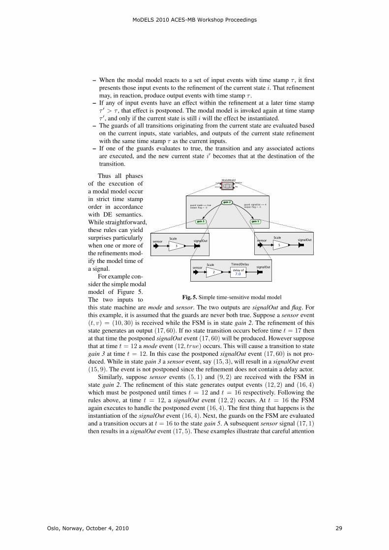
– When the modal model reacts to a set of input events with time stamp τ , it firstpresents those input events to the refinement of the current state i. That refinementmay, in reaction, produce output events with time stamp τ .
– If any of input events have an effect within the refinement at a later time stampτ ′ > τ , that effect is postponed. The modal model is invoked again at time stampτ ′, and only if the current state is still i will the effect be instantiated.
– The guards of all transitions originating from the current state are evaluated basedon the current inputs, state variables, and outputs of the current state refinementwith the same time stamp τ as the current inputs.
– If one of the guards evaluates to true, the transition and any associated actionsare executed, and the new current state i′ becomes that at the destination of thetransition.
Fig. 5. Simple time-sensitive modal model
Thus all phasesof the execution ofa modal model occurin strict time stamporder in accordancewith DE semantics.While straightforward,these rules can yieldsurprises particularlywhen one or more ofthe refinements mod-ify the model time ofa signal.
For example con-sider the simple modalmodel of Figure 5.The two inputs tothis state machine are mode and sensor. The two outputs are signalOut and flag. Forthis example, it is assumed that the guards are never both true. Suppose a sensor event(t, v) = (10, 30) is received while the FSM is in state gain 2. The refinement of thisstate generates an output (17, 60). If no state transition occurs before time t = 17 thenat that time the postponed signalOut event (17, 60) will be produced. However supposethat at time t = 12 a mode event (12, true) occurs. This will cause a transition to stategain 3 at time t = 12. In this case the postponed signalOut event (17, 60) is not pro-duced. While in state gain 3 a sensor event, say (15, 3), will result in a signalOut event(15, 9). The event is not postponed since the refinement does not contain a delay actor.
Similarly, suppose sensor events (5, 1) and (9, 2) are received with the FSM instate gain 2. The refinement of this state generates output events (12, 2) and (16, 4)which must be postponed until times t = 12 and t = 16 respectively. Following therules above, at time t = 12, a signalOut event (12, 2) occurs. At t = 16 the FSMagain executes to handle the postponed event (16, 4). The first thing that happens is theinstantiation of the signalOut event (16, 4). Next, the guards on the FSM are evaluatedand a transition occurs at t = 16 to the state gain 5. A subsequent sensor signal (17, 1)then results in a signalOut event (17, 5). These examples illustrate that careful attention
MoDELS 2010 ACES-MB Workshop Proceedings
Oslo, Norway, October 4, 2010 29
must be paid to the temporal semantics of the modal models to ensure that the desiredapplication behavior results.
4 Application Study
PTIDES can be used to integrate models of software, networks, and physical plants.This is achieved by adopting the fixed-point semantics that makes it possible to mixcontinuous and discrete-event models [16]. A practical consequence is to enable CPSco-design and co-simulation. It also facilitates hardware in the loop (HIL) simulation,where deployable software can be tested (at greatly reduced cost and risk) against sim-ulations of the physical plant. The DE semantics of the model ensures that simulationswill match implementations, even if the simulation of the plant cannot execute in realtime. Conversely, prototypes of the software on generic execution platforms can betested against the actual physical plant. The model can be tested even if the softwarecontrollers are not fully implemented. This (extremely valuable) property cannot beachieved today because the temporal properties of the software emerge from an im-plementation, and therefore complete tests of the dynamics often cannot be performeduntil the final stages of system integration, with the actual physical plant, using the finalplatform.
The inclusion of a network into an embedded system introduces three principalcomplications in the design of embedded systems:
– To preserve DE semantics and the resulting determinism system wide, it is neces-sary to provide a common sense of time to all platforms. As noted in section 2 thisis often based on a time-slotted network protocol but can also be based on a clocksynchronization protocol such as IEEE 1588 [9].
– The design of model delays must now account not only for execution time within anactuation platform, e.g. the platform containing an actuator causally dependent onsignals from other platforms, but must include network delay as well as executiontime in platforms providing signals via the network to the actuation platform.
– To ensure bounded network delay it is usually necessary to enforce some sort ofadmission control explicitly controlling the time that traffic is introduced onto thenetwork.
The introduction of timed reactions further complicates the design and analysis ofsystem temporal semantics, particularly when these reactions must be synchronizedacross a multi-platform system. PTIDES is well suited in managing these multi-platformdesign issues. The remainder of this section illustrates the following features of thePTIDES design environment:
– The use of time-based detection of missing signals to drive mode changes in theoperation of power plants.
– The use of time-based models of the plant in testing controller implementations ofpower plants.
– The use of a modal model to specify the temporal behavior of the operational modesof a device.
MoDELS 2010 ACES-MB Workshop Proceedings
Oslo, Norway, October 4, 2010 30

– The use of synchronized clocks in a multi-platform system to allow FSMs and otheractors in each platform to enforce system-wide temporal behavior.
– The enforcement of correspondence between model and physical time at sensorsand actuators to ensure that such timing specifications are realized
– The enforcement at platform network outputs of sending deadlines to ensure thatmulti-platform feasible solutions are computable.
Power Plant Control.
Fig. 6. Model of a small power plant
The design of the con-trol systems for large electricpower stations is interesting inthat the physical extent of theplant requires a networked so-lution. The two critical designissues of interest here are theprecision of the turbine speedcontrol loop and the systemreaction time to failures. Theloop time is relatively long butfor serious failures the fuelsupply to the turbine must typ-ically be reduced within a fewmilliseconds. A typical powerplant can involve samplingof up to 3000 nodes com-prising monitoring equipmentseparated by several hundredmeters. Since the purpose ofthese data is to make decisionsabout the state of the physi-cal plant, it is critical that thetime at which each measure-ment is made be known toan accuracy and precision ap-propriate to the physics beingmeasured. The PTIDES de-sign system allows these mea-surement times to be preciselyspecified and time-stampedwith respect to the synchro-nized real-time clocks in theseparate platforms.
Figure 6 illustrates a modelof a power plant that is hopefully readable without much additional explanation. Themodel includes a Generator/Turbine Model, which models continuous dynamics, amodel of a communication network, and a model the supervisory controller. The de-tails of these three components are not shown. Indeed, each of these three components
MoDELS 2010 ACES-MB Workshop Proceedings
Oslo, Norway, October 4, 2010 31
can be quite sophisticated models, although for our purposes here will use rather sim-ple versions. The model in Figure 6 also includes a local controller, which is expandedshowing two main components, a Heartbeat Detector and Plant Control block. A powerplant, like many CPS, can be characterized by several modes of operation each of whichcan have different time semantics. This is reflected in the design of the Plant Controlblock that is implemented with a four state modal model based on the discussion ofsection 3 . The Down state represents the off state of the power plant. Upon receipt of a(time-stamped) startup event from the supervisory controller, this modal model transi-tions to the Startup state. When the measured discrepancy between electric power outputand the target output gets below a threshold given by errorThreshold, the modal modeltransitions to the Normal state. If it receives a (time-stamped) emergency event fromthe Heartbeat Detector, then it will transition to the Shutdown state, and after achievingshutdown, to the Down state. Each of these states has a refinement (not shown) that usesinput sensor data to specify the amount of fuel to supply to the generator/turbine. Thefuel amount is sent over the network to the actuators on the generator/turbine. Becauseboth the controller sensor input data and the resulting fuel control signal sent to theactuators are time stamped, the designer is able to use PTIDES construct to preciselyspecify the delay between sensors and actuators. Furthermore as described earlier exe-cutable code generated from the PTIDES models shown here, forces these time stampsto correspond to physical time at both sensors and actuators thus ensuring determin-istic and temporally correct execution meeting the designed specifications even acrossmultiple platforms linked by a network.
electricOutputoperatingTarget
fuel
01
2
3
4
5
0 5 10 15 20 25 30 35 40
Plant Input (fuel), Output, and Operating Target
statesensor
clockemergency
warning
-4-3-2
-10
12
3
0 5 10 15 20 25 30 35 40
Heartbeat and Plant State Display
time
Warning Emergency
DownStartup
NormalShutdown
Down
Fig. 7. Power plant output and events
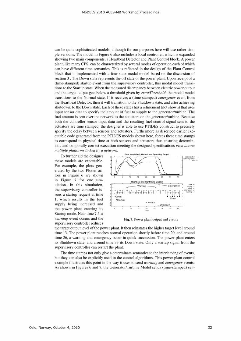
To further aid the designerthese models are executable.For example, the plots gen-erated by the two Plotter ac-tors in Figure 6 are shownin Figure 7 for one sim-ulation. In this simulation,the supervisory controller is-sues a startup request at time1, which results in the fuelsupply being increased andthe power plant entering itsStartup mode. Near time 7.5, awarning event occurs and thesupervisory controller reducesthe target output level of the power plant. It then reinstates the higher target level aroundtime 13. The power plant reaches normal operation shortly before time 20, and aroundtime 26, a warning and emergency occur in quick succession. The power plant entersits Shutdown state, and around time 33 its Down state. Only a startup signal from thesupervisory controller can restart the plant.
The time stamps not only give a determinate semantics to the interleaving of events,but they can also be explicitly used in the control algorithms. This power plant controlexample illustrates this point in the way it uses to send warning and emergency events.As shown in Figures 6 and 7, the Generator/Turbine Model sends (time-stamped) sen-
MoDELS 2010 ACES-MB Workshop Proceedings
Oslo, Norway, October 4, 2010 32
sor readings over the network to the Local Control component. These sensor eventsare shown with “x” symbols in Figure 7. Notice that just prior to each warning event,there is a gap in these sensor events. Indeed, this Local Control component declares awarning if between any two local clock ticks it fails to receive a sensor reading from theGenerator/Turbine Model. If a second consecutive interval between clock ticks elapseswithout a sensor message arriving, it declares an emergency and initiates shutdown.
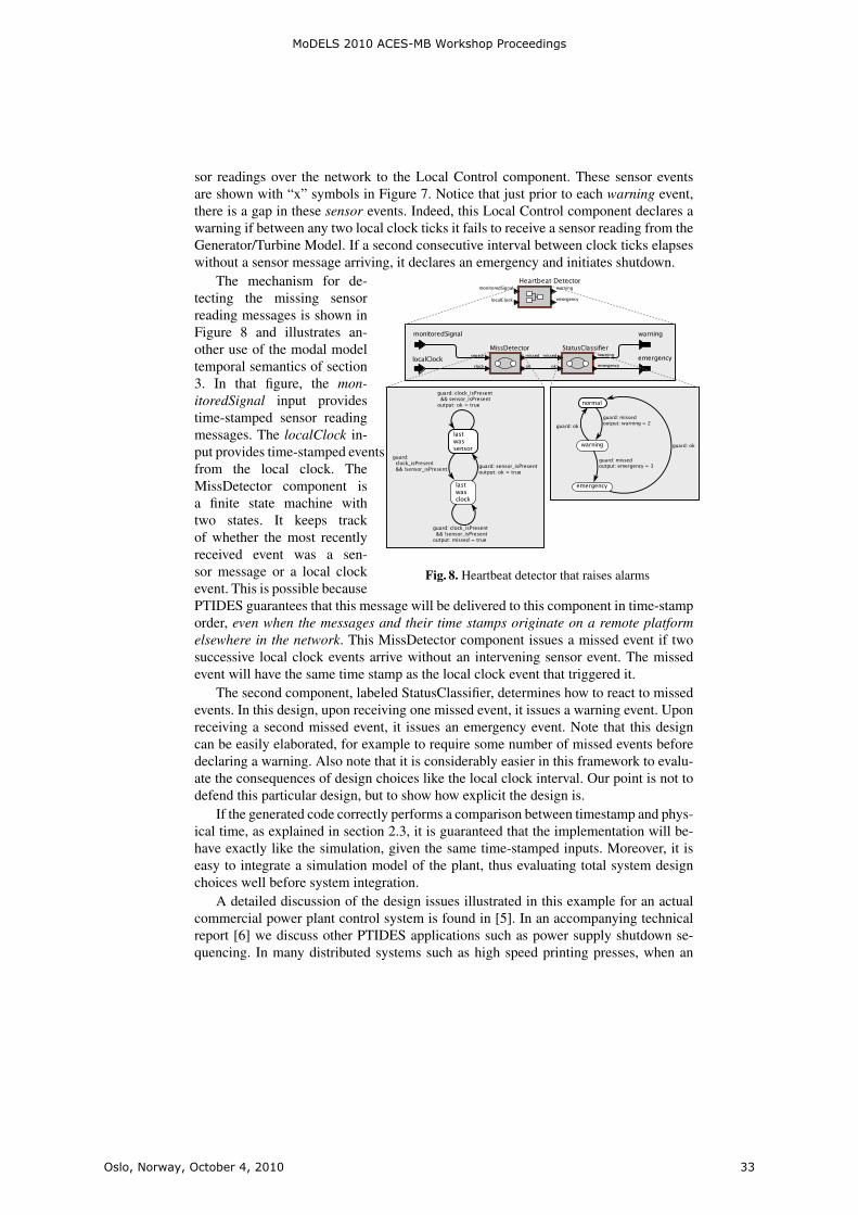
Fig. 8. Heartbeat detector that raises alarms
The mechanism for de-tecting the missing sensorreading messages is shown inFigure 8 and illustrates an-other use of the modal modeltemporal semantics of section3. In that figure, the mon-itoredSignal input providestime-stamped sensor readingmessages. The localClock in-put provides time-stamped eventsfrom the local clock. TheMissDetector component isa finite state machine withtwo states. It keeps trackof whether the most recentlyreceived event was a sen-sor message or a local clockevent. This is possible becausePTIDES guarantees that this message will be delivered to this component in time-stamporder, even when the messages and their time stamps originate on a remote platformelsewhere in the network. This MissDetector component issues a missed event if twosuccessive local clock events arrive without an intervening sensor event. The missedevent will have the same time stamp as the local clock event that triggered it.
The second component, labeled StatusClassifier, determines how to react to missedevents. In this design, upon receiving one missed event, it issues a warning event. Uponreceiving a second missed event, it issues an emergency event. Note that this designcan be easily elaborated, for example to require some number of missed events beforedeclaring a warning. Also note that it is considerably easier in this framework to evalu-ate the consequences of design choices like the local clock interval. Our point is not todefend this particular design, but to show how explicit the design is.
If the generated code correctly performs a comparison between timestamp and phys-ical time, as explained in section 2.3, it is guaranteed that the implementation will be-have exactly like the simulation, given the same time-stamped inputs. Moreover, it iseasy to integrate a simulation model of the plant, thus evaluating total system designchoices well before system integration.
A detailed discussion of the design issues illustrated in this example for an actualcommercial power plant control system is found in [5]. In an accompanying technicalreport [6] we discuss other PTIDES applications such as power supply shutdown se-quencing. In many distributed systems such as high speed printing presses, when an
MoDELS 2010 ACES-MB Workshop Proceedings
Oslo, Norway, October 4, 2010 33
emergency shutdown signal is received, one cannot simply turn off power throughoutthe system. Instead, a carefully orchestrated shutdown sequence needs to be performed.During this sequence, different parts of the system will have different timing relation-ships with the primary shutdown signal. As presented in [6], this relationship is easilycaptured in the timed semantics of PTIDES.
5 Conclusion
This paper reviewed Ptolemy II enhancements for several important aspects of CPSdesign and deployment, namely PTIDES for distributed real-time systems, and modalmodels for multi-mode system behavior. The timed semantics of PTIDES allows us tospecify the interaction between the control program and the physical dynamics in thesystem model, independent of underlying hardware details. Because of this indepen-dence, PTIDES models are more robust than typical real-time software, because smallchanges in the physical execution timing of internal events are not visible to the en-vironment, as long as real-time constraints are met at sensors, actuators and networkinterfaces. By combining PTIDES with modal models, we illustrated timed mode tran-sitions which enable time-based detection of missing signals to drive mode changes inthe operation of common industrial applications.
Our future activities include work on several components of the PTIDES frame-work. PTIDES relies on software components providing information about model delaythey introduce. This information is captured by causality interfaces [27], and causalityanalysis is used to ensure that DE semantics is preserved in an execution. The precisecausality analysis when modal models are allowed is undecidable in general, but weexpect that common use cases will yield to effective analysis. Another challenge is toprovide feasibility analysis for the PTIDES programming model, which would allowfor a static analysis of the deployability of a given application on a set of resources.
A major component of our work will be refinement to the design of a distributedexecution platform for PTIDES. The code generator integrated within the Ptolemy IIenvironment will generate C code from PTIDES models and glue them together withthe preexisting software components to produce executable programs for each of theplatforms in the network. The code will be executed in the context of PtidyOS that canbe considered as a lightweight operating system with PTIDES semantics.
References
1. G. Berry. The effectiveness of synchronous languages for the development of safety-criticalsystems. White paper, Esterel Technologies, 2003.
2. S. Bliudze and J. Sifakis. The algebra of connectors: structuring interaction in bip. InEMSOFT, pages 11–20. ACM, 2007.
3. C. G. Cassandras. Discrete Event Systems, Modeling and Performance Analysis. Irwin, 1993.4. K. M. Chandy and J. Misra. Distributed simulation: A case study in design and verification
of distributed programs. IEEE Transaction on Software Engineering, 5(5), 1979.5. J. C. Eidson. Measurement, Control, and Communication Using IEEE 1588, pages 194–200.
Springer, London, 2006.6. J. C. Eidson, E. A. Lee, S. Matic, S. A. Seshia, and J. Zou. Time-centric models for de-
signing embedded cyber-physical systems. Technical Report UCB/EECS-2009-135, EECSDepartment, University of California, Berkeley, Oct 2009.
MoDELS 2010 ACES-MB Workshop Proceedings
Oslo, Norway, October 4, 2010 34
7. J. Eker, J. W. Janneck, E. A. Lee, J. Liu, X. Liu, J. Ludvig, S. Neuendorffer, S. Sachs,and Y. Xiong. Taming heterogeneity—the ptolemy approach. Proceedings of the IEEE,91(2):127–144, 2003.
8. D. Harel. Statecharts: A visual formalism for complex systems. Science of Computer Pro-gramming, 8:231–274, 1987.
9. IEEE Instrumentation and Measurement Society. 1588: IEEE standard for a precision clocksynchronization protocol for networked measurement and control systems. Standard speci-fication, IEEE, July 24 2008.
10. M. Jersak. Timing model and methodology for autosar. In Elektronik Automotive. Specialissue AUTOSAR, 2007.
11. G. Karsai, J. Sztipanovits, A. Ledeczi, and T. Bapty. Model-integrated development of em-bedded software. Proceedings of the IEEE, 91(1):145–164, 2003.
12. H. Kopetz and G. Bauer. The time-triggered architecture. Proceedings of the IEEE,91(1):112–126, 2003.
13. E. A. Lee. Modeling concurrent real-time processes using discrete events. Annals of SoftwareEngineering, 7:25–45, 1999.
14. E. A. Lee. Finite state machines and modal models in ptolemy ii. Technical ReportUCB/EECS-2009-151, EECS Department, University of California, Berkeley, Nov 2009.
15. E. A. Lee and A. Sangiovanni-Vincentelli. A framework for comparing models of computa-tion. IEEE Transactions on Computer-Aided Design of Circuits and Systems, 17(12):1217–1229, 1998.
16. E. A. Lee and H. Zheng. Leveraging synchronous language principles for heterogeneousmodeling and design of embedded systems. In EMSOFT, Salzburg, Austria, 2007. ACM.
17. P. Levis, S. Madden, D. Gay, J. Polastre, R. Szewczyk, A. Woo, E. Brewer, and D. Culler.The emergence of networking abstractions and techniques in tinyos. In First USENIX/ACMSymposium on Networked Systems Design and Implementation (NSDI 2004), 2004.
18. X. Liu and E. A. Lee. CPO semantics of timed interactive actor networks. TheoreticalComputer Science, 409(1):110–125, 2008.
19. R. Makowitz and C. Temple. FlexRay-a communication network for automotive controlsystems. In 2006 IEEE International Workshop on Factory Communication Systems, pages207–212, 2006.
20. Mathworks. Matlab. http://www.mathworks.com/products/matlab/, 1996.21. R. Olfati-Saber, J. A. Fax, and R. M. Murray. Consensus and cooperation in networked
multi-agent systems. Proceedings of the IEEE, 95(1):215–233, 2007.22. O.M.G. U.m.l. specification Version 1.3. Object Management Group, 1999.23. OMG. Uml profile for modeling and analysis of real-time and embedded systems (marte).
http://www.omgmarte.org/, 2008.24. K. Tindell, H. Hansson, and A. Wellings. Analysing real-time communications: Controller
area network (CAN). In Proceedings 15th IEEE Real-Time Systems Symposium, pages 259–265. Citeseer, 1994.
25. B. P. Zeigler, H. Praehofer, and T. G. Kim. Theory of Modeling and Simulation. AcademicPress, 2nd edition, 2000.
26. Y. Zhao, E. A. Lee, and J. Liu. A programming model for time-synchronized distributedreal-time systems. In Real-Time and Embedded Technology and Applications Symposium(RTAS), Bellevue, WA, USA, 2007. IEEE.
27. Y. Zhou and E. A. Lee. Causality interfaces for actor networks. ACM Transactions onEmbedded Computing Systems (TECS), 7(3):1–35, 2008.
28. J. Zou, S. Matic, E. Lee, T. Feng, and P. Derler. Execution strategies for ptides, a program-ming model for distributed embedded systems. In Real-Time and Embedded Technology andApplications Symposium (RTAS), San Francisco, CA, USA, 2009. IEEE.
MoDELS 2010 ACES-MB Workshop Proceedings
Oslo, Norway, October 4, 2010 35


From Interaction Overview Diagramsto Temporal Logic
Luciano Baresi, Angelo Morzenti, Alfredo Motta, Matteo Rossi
Politecnico di MilanoDipartimento di Elettronica e Informazione, Deep-SE Group
Via Golgi 42 – 20133 Milano, Italy(baresi|morzenti|motta|rossi)@elet.polimi.it
Abstract. In this paper, we use UML Interaction Overview Diagramsas the basis for a user-friendly, intuitive, modeling notation that is well-suited for the design of complex, heterogeneous, embedded systems de-veloped by domain experts with little background on modeling software-based systems. To allow designers to precisely analyze models writtenwith this notation, we provide (part of) it with a formal semantics basedon temporal logic, upon which a fully automated, tool supported, ver-ification technique is built. The modeling and verification technique ispresented and discussed through the aid of an example system.Keywords: Metric temporal logic, bounded model checking, UnifiedModeling Language.
1 Introduction
Complex embedded systems such as those found in the Aerospace and Defensedomains are typically built of several, heterogeneous, components that are oftendesigned by teams of engineers with different backgrounds (e.g., telecommuni-cation, control systems, software engineering, etc.). Careful modeling startingfrom the early stages of system development can greatly help increase the qual-ity of the designed system when it is accompanied and followed by verificationand code generation activities. Modeling-verification-code generation are threepillars in the model driven development of complex embedded systems; they aremost effective when (i) modeling is based on user-friendly, intuitive, yet precisenotations that can be used with ease by experts of domains other than computerscience; (ii) rigorous, possibly formal, verification can be carried out on the afore-mentioned models, though in a way that is hidden from the system developer asmuch as possible; (iii) executable code can be seamlessly produced from verifiedmodels, to generate implementations that are correct by construction.
This work, which is part of a larger research effort carried out in the MADESEuropean project1 [1], focuses on aspects (i) and (ii) mentioned above. In partic-ular, it is the first step towards a complete proposal for modeling and validatingembedded systems. The plan is to exploit both “conventional” UML diagrams
1 http://www.mades-project.org
MoDELS 2010 ACES-MB Workshop Proceedings
Oslo, Norway, October 4, 2010 37
2
[15] and a subset of the MARTE (Modeling and Analysis of Real-Time and Em-bedded systems) UML profile [14]. We want to use Class Diagrams to define thekey components of the system. State Diagrams to model their internal behaviors,and Sequence and Interaction Overview Diagrams to model the interactions andcooperations among the different elements. These diagrams will be augmentedwith clocks and resources taken from MARTE. The result is a multi-facetedmodel of the system, automatically translated into temporal logic to verify it.Temporal Logic helps glue the different views, create a single, consistent rep-resentation of the system, discover inconsistencies among the different aspects,and formally verify some global properties.
This paper starts from Interaction Overview Diagrams (IODs) since they areoften neglected, but they provide an interesting means to integrate SequenceDiagrams (SDs) and define coherent and complex evolutions of the system ofinterest. IODs are ascribed a formal semantics, based on temporal logic, uponwhich a fully automated, tool supported, verification technique is built.
The choice of IODs as the starting point for a modeling notation that isaccessible to experts of different domains, especially those other than softwareengineering, is borne from the observation that, in the industrial practice, SDsare often the preferred notation of system engineers to describe components’behaviors [3]. However, SDs taken in isolation are not enough to provide a com-plete picture of the interactions among the various components of a complexsystem; hence, system designers must be given mechanisms to combine differentSDs into richer descriptions, which is precisely what IODs offer.
IODs cannot be used to perform the kind of rigorous analysis that is cru-cial throughout the development of critical systems such as those typical of theAerospace and Defense domains unless they are given a precise semantics. Tothis end, in this article we provide a preliminary formal semantics of IODs basedon metric temporal logic. While this semantics is not yet complete, as it does notcover all possible mechanisms through which SDs can be combined into IODs,it is nonetheless a significant first step in this direction. The provided semanticshas been implemented into the Zot bounded satisfiability/model checker [16]2,and has been used to prove some properties of an example system.
This paper is structured as follows. Section 2 briefly presents IODs; Section 3gives an overview of the metric temporal logic used to define the formal semanticsof IODs, and of the Zot tool supporting it; Section 4 introduces the formalsemantics of IODs through an example system, and discusses how it has beenused to prove properties of the latter; Section 5 discusses some relevant relatedworks; finally, Section 6 draws some conclusions and outlines future works.
2 Interaction Overview Diagrams
Most UML behavioral diagrams have undergone a significant revision from ver-sion 1.x to version 2.x To model interactions, UML2 offers four kinds of diagrams:
2 Zot is available at http://home.dei.polimi.it/pradella.
MoDELS 2010 ACES-MB Workshop Proceedings
Oslo, Norway, October 4, 2010 38

3
communication diagrams, sequence diagrams, timing diagrams and interactionoverview diagrams. In this work we focus on Sequence Diagrams (SDs) and In-teraction Overview Diagrams (IODs).
SDs have been considerably revised and extended in UML2 to improve theirexpressiveness and their structure. IODs are new in UML2. They allow a de-signer to provide a high-level view of the possible interactions in a system. IODsconstitute a high-level structuring mechanism that is used to compose scenariosthrough mechanisms such as sequence, iteration, concurrency or choice. IODsare a special and restricted kind of UML Activity Diagrams (ADs) where nodesare interactions or interaction uses, and edges indicate the flow or order in whichthese interactions occur. Semantically, however, IODs are more complex com-pared to ADs and may have different interpretations. In the following the funda-mental operators of IODs are presented. Figure 2 shows an example of IOD forthe application analyzed in Section 4, which will be used throughout this Sec-tion to provide graphical examples of IOD constructs. IODs include also otheroperators whose study is left to future works.
2.1 Initial Node/Final Node/Flow Final Node
In IODs these operators have exactly the same meaning of the correspondingoperators found in ADs.
An initial node is a type of control node which initiates flow in a IOD. It hasno incoming flows and one or more outgoing flows. The outgoing flows may beguarded with conditions that determine if they will accept tokens. When a IODstarts, tokens are offered to all outgoing flows of the initial node.
A final node is a node that stops a IOD. When a token arrives at a final nodeall flows in the enclosing activity are stopped and the IOD is terminated. Thetoken arriving at the final node is destroyed.
Finally, a flow final node is a type of final node that consumes the incomingtoken. When a token arrives at a flow final node the token is consumed andnothing else in the IOD is affected.
The IOD of Figure 2 has an initial node at the top, but no final or flow finalnodes.
2.2 Control Flow
A control flow is a directed connection (flow) between two SDs (e.g., betweendiagrams delegateSMS and downloadSMS in Figure 2). As soon as the SD atthe source of the flow is finished, it presents a token to the SD at the end of theflow.
2.3 Fork/Join
A fork node is a control node that has a single incoming flow and two or moreoutgoing flows. Incoming tokens are offered to all outgoing flows (edges). The
MoDELS 2010 ACES-MB Workshop Proceedings
Oslo, Norway, October 4, 2010 39

4
outgoing flows can be guarded, which gives them a mechanism to accept or rejecta token. If one of the outgoing flows accepts the token, the token is duplicatedfor that flow. In this work we do not deal with guards, but this is a ratherstraightforward extension that we will consider in the future. In the IOD ofFigure 2, there is one fork node at the top of the diagram (between the initialnode and SDs waitingCall and checkingSMS ) modeling two concurrent executionof the system.
The dual operator is the join node, which synchronizes a number of incomingflows into a single outgoing flow. Each (and every) incoming control flow mustpresent a control token to the join node before the node can offer a single tokento the outgoing flow.
2.4 Decision/Merge
A decision node is a control node that has one incoming flow and two or moreoutgoing flows. When a token arrives at a decision node it is offered to all theoutgoing flows, one (and only one) of which accepts the token. In the IOD ofFigure 2 there are four decision operators (e.g., the one between SDs waitingCalland delegateCall) with their corresponding boolean conditions.
Conversely, the merge node is a type of control node that has two or moreincoming flows and a single outgoing flow. It is used to reunite alternative flowsthat originate from one or more decision nodes. The merge node accepts a tokenon any one (and only one) of the incoming flows and passes it to the singleoutgoing flow.
3 TRIO and Zot
TRIO [7] is a general-purpose formal specification language suitable for describ-ing complex real-time systems, including distributed ones. TRIO is a first-orderlinear temporal logic that supports a metric on time. TRIO formulae are builtout of the usual first-order connectives, operators, and quantifiers, as well as asingle basic modal operator, called Dist, that relates the current time, whichis left implicit in the formula, to another time instant: given a time-dependentformula F (i.e., a term representing a mapping from the time domain to truthvalues) and a (arithmetic) term t indicating a time distance (either positive ornegative), the formula Dist(F, t) specifies that F holds at a time instant whosedistance is exactly t time units from the current instant. Dist(F, t) is in turn alsoa time-dependent formula, as its truth value can be evaluated for any currenttime instant, so that temporal formulae can be nested as usual. While TRIOcan exploit both discrete and dense sets as time domains, in this paper we as-sume the standard model of the nonnegative integers N as discrete time domain.For convenience in the writing of specification formulae, TRIO defines a numberof derived temporal operators from the basic Dist, through propositional com-position and first-order logic quantification. Table 1 defines some of the mostsignificant ones, including those used in this paper.
MoDELS 2010 ACES-MB Workshop Proceedings
Oslo, Norway, October 4, 2010 40
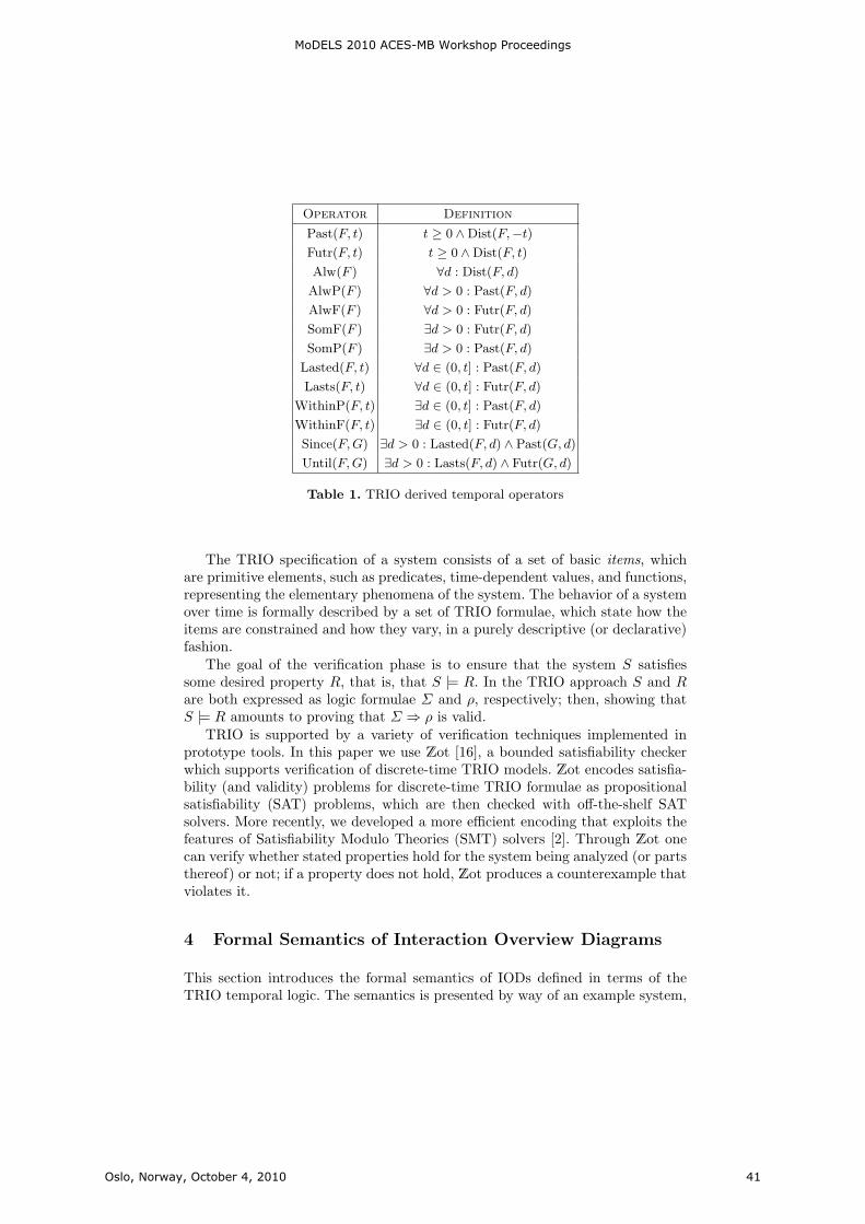
5
Operator Definition
Past(F, t) t ≥ 0 ∧Dist(F,−t)Futr(F, t) t ≥ 0 ∧Dist(F, t)
Alw(F ) ∀d : Dist(F, d)
AlwP(F ) ∀d > 0 : Past(F, d)
AlwF(F ) ∀d > 0 : Futr(F, d)
SomF(F ) ∃d > 0 : Futr(F, d)
SomP(F ) ∃d > 0 : Past(F, d)
Lasted(F, t) ∀d ∈ (0, t] : Past(F, d)
Lasts(F, t) ∀d ∈ (0, t] : Futr(F, d)
WithinP(F, t) ∃d ∈ (0, t] : Past(F, d)
WithinF(F, t) ∃d ∈ (0, t] : Futr(F, d)
Since(F,G) ∃d > 0 : Lasted(F, d) ∧ Past(G, d)
Until(F,G) ∃d > 0 : Lasts(F, d) ∧ Futr(G, d)
Table 1. TRIO derived temporal operators
The TRIO specification of a system consists of a set of basic items, whichare primitive elements, such as predicates, time-dependent values, and functions,representing the elementary phenomena of the system. The behavior of a systemover time is formally described by a set of TRIO formulae, which state how theitems are constrained and how they vary, in a purely descriptive (or declarative)fashion.
The goal of the verification phase is to ensure that the system S satisfiessome desired property R, that is, that S |= R. In the TRIO approach S and Rare both expressed as logic formulae Σ and ρ, respectively; then, showing thatS |= R amounts to proving that Σ ⇒ ρ is valid.
TRIO is supported by a variety of verification techniques implemented inprototype tools. In this paper we use Zot [16], a bounded satisfiability checkerwhich supports verification of discrete-time TRIO models. Zot encodes satisfia-bility (and validity) problems for discrete-time TRIO formulae as propositionalsatisfiability (SAT) problems, which are then checked with off-the-shelf SATsolvers. More recently, we developed a more efficient encoding that exploits thefeatures of Satisfiability Modulo Theories (SMT) solvers [2]. Through Zot onecan verify whether stated properties hold for the system being analyzed (or partsthereof) or not; if a property does not hold, Zot produces a counterexample thatviolates it.
4 Formal Semantics of Interaction Overview Diagrams
This section introduces the formal semantics of IODs defined in terms of theTRIO temporal logic. The semantics is presented by way of an example system,
MoDELS 2010 ACES-MB Workshop Proceedings
Oslo, Norway, October 4, 2010 41
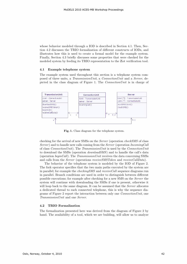
6
whose behavior modeled through a IOD is described in Section 4.1. Then, Sec-tion 4.2 discusses the TRIO formalization of different constructs of IODs, andillustrates how this is used to create a formal model for the example system.Finally, Section 4.3 briefly discusses some properties that were checked for themodeled system by feeding its TRIO representation to the Zot verification tool.
4.1 Example telephone system
The example system used throughout this section is a telephone system com-posed of three units, a TransmissionUnit, a ConnectionUnit and a Server, de-picted in the class diagram of Figure 1. The ConnectionUnit is in charge of
Fig. 1. Class diagram for the telephone system.
checking for the arrival of new SMSs on the Server (operation checkSMS of classServer) and to handle new calls coming from the Server (operation IncomingCallof class ConnectionUnit). The TransmissionUnit is used by the ConnectionUnitto download the SMSs (operation downloadSMS ) and to handle the call’s data(operation beginCall). The TransmissionUnit receives the data concerning SMSsand calls from the Server (operations receiveSMSToken and receiveCallData).
The behavior of the telephone system is modeled by the IOD of Figure 2.The fork operator specifies that the two main paths executed by the system arein parallel; for example the checkingSMS and receiveCall sequence diagrams runin parallel. Branch conditions are used in order to distinguish between differentpossible executions; for example after checking for a new SMS on the Server thesystem will continue with downloading the SMSs if one is present, otherwise itwill loop back to the same diagram. It can be assumed that the Server allocatesa dedicated thread to each connected telephone, this is why the sequence dia-grams of Figure 2 report the interaction between only one ConnectionUnit, oneTransmissionUnit and one Server.
4.2 TRIO Formalization
The formalization presented here was derived from the diagram of Figure 2 byhand. The availability of a tool, which we are building, will allow us to analyze
MoDELS 2010 ACES-MB Workshop Proceedings
Oslo, Norway, October 4, 2010 42

7
Fig. 2. Interaction Overview diagram for the telephone system.
MoDELS 2010 ACES-MB Workshop Proceedings
Oslo, Norway, October 4, 2010 43
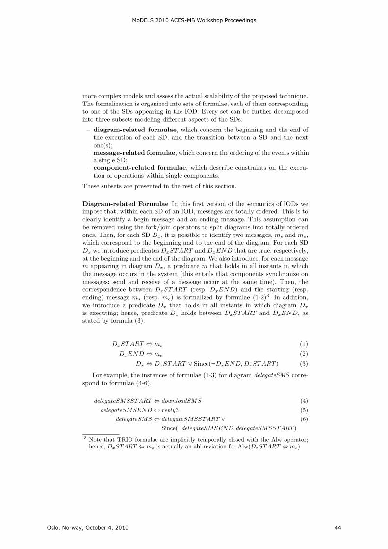
8
more complex models and assess the actual scalability of the proposed technique.The formalization is organized into sets of formulae, each of them correspondingto one of the SDs appearing in the IOD. Every set can be further decomposedinto three subsets modeling different aspects of the SDs:
– diagram-related formulae, which concern the beginning and the end ofthe execution of each SD, and the transition between a SD and the nextone(s);
– message-related formulae, which concern the ordering of the events withina single SD;
– component-related formulae, which describe constraints on the execu-tion of operations within single components.
These subsets are presented in the rest of this section.
Diagram-related Formulae In this first version of the semantics of IODs weimpose that, within each SD of an IOD, messages are totally ordered. This is toclearly identify a begin message and an ending message. This assumption canbe removed using the fork/join operators to split diagrams into totally orderedones. Then, for each SD Dx, it is possible to identify two messages, ms and me,which correspond to the beginning and to the end of the diagram. For each SDDx we introduce predicates DxSTART and DxEND that are true, respectively,at the beginning and the end of the diagram. We also introduce, for each messagem appearing in diagram Dx, a predicate m that holds in all instants in whichthe message occurs in the system (this entails that components synchronize onmessages: send and receive of a message occur at the same time). Then, thecorrespondence between DxSTART (resp. DxEND) and the starting (resp.ending) message ms (resp. me) is formalized by formulae (1-2)3. In addition,we introduce a predicate Dx that holds in all instants in which diagram Dx
is executing; hence, predicate Dx holds between DxSTART and DxEND, asstated by formula (3).
DxSTART ⇔ ms (1)
DxEND ⇔ me (2)
Dx ⇔ DxSTART ∨ Since(¬DxEND,DxSTART ) (3)
For example, the instances of formulae (1-3) for diagram delegateSMS corre-spond to formulae (4-6).
delegateSMSSTART ⇔ downloadSMS (4)
delegateSMSEND ⇔ reply3 (5)
delegateSMS ⇔ delegateSMSSTART ∨ (6)
Since(¬delegateSMSEND, delegateSMSSTART )
3 Note that TRIO formulae are implicitly temporally closed with the Alw operator;hence, DxSTART ⇔ ms is actually an abbreviation for Alw(DxSTART ⇔ ms) .
MoDELS 2010 ACES-MB Workshop Proceedings
Oslo, Norway, October 4, 2010 44

9
Notice that if the IOD contains k different occurrences of the same messagem, k different predicates m0...mk are introduced. For this reason in formula (5)reply3 appears instead of reply.
A diagram Dx is followed by a diagram Dy for either of two reasons: (1) Dx
is directly connected to Dy, in this case the end of Dx is the necessary conditionto start Dy; (2) Dx is connected to Dy through some decision operator, in thiscase the necessary condition to start Dy is given by the end of Dx, providedthe condition on the decision operator is met. If a diagram Dx is preceded byp sequence diagrams, we introduce p predicates DxACTCi (i ∈ {1...p}), whereDxACTCi holds if the i-th necessary condition to start diagram Dx holds. Wealso introduce predicate DxACT , which holds the instant after any of the pnecessary conditions holds, as defined by formula (7). This is done to avoid thatDxSTART andDyEND are true at the same time instant, withDy ∈ {1...p}. Infact a condition DxACTCi holds when the ending predicate of the i-th diagramthat precedes Dx hold. After the necessary condition to start a diagram is met,the diagram will start at some point in the future (not necessarily immediately),as stated by formula (8). Finally, after a diagram starts, it cannot start againuntil the necessary condition to start it is met anew, as defined by formula (9).
DxACT ⇔ Past(DxACTC0 ∨ ... ∨DxACTCm, 1) (7)
DxACT ⇒ SomF(DxSTART ) ∨DxSTART (8)
DxSTART ⇒ ¬SomF(DxSTART ) ∨Until(¬DxSTART,DxACT ) (9)
In the case of SD downloadSMS of Figure 2, the instances of formulae (7-9)are given by (12-14). In addition, formulae (10-11) define the necessary conditionsto start diagram downloadSMS : either diagram delegateSMS ends, or diagramdownloadSMS ends and condition moredata holds. Currently, we can only dealwith atomic boolean conditions. The representation of more complex data, andconditions upon them, is already in our research agenda.
downloadSMSACTC1 ⇔ delegateSMSEND (10)
downloadSMSACTC2 ⇔ downloadSMSEND ∧moredata (11)
downloadSMSACT ⇔ Past
(downloadSMSACTC1
∨ downloadSMSACTC2
)(12)
downloadSMSACT ⇒SomFe(downloadSMSSTART ) ∨ downloadSMSSTART (13)
downloadSMSSTART ⇒¬SomFe(downloadSMSSTART ) ∨Until(¬downloadSMSSTART, downloadSMSACT ) (14)
MoDELS 2010 ACES-MB Workshop Proceedings
Oslo, Norway, October 4, 2010 45
10
Message-related Formulae Suppose that, in a SD, a message mi is followedby another message mj . Then the occurrence of mi entails that mj will alsooccur in the future; conversely, the occurrence of mj entails that mi must haveoccurred in the past. This is formally defined by formulae (15-16). In addition,after an instance of mj , there can be a new instance of the same message onlyafter a new occurrence of mi; this is stated by formula (17), which defines that,after mj , there will not be a new occurrence of mj until there is an occurrenceof mi.
mi ⇒ SomF(mj) ∧ ¬mj (15)
mj ⇒ SomP(mi) ∧ ¬mi (16)
mj ⇒ ¬SomF(mj) ∨Until(¬mj ,mi) (17)
If, for example, formulae (15-17) are instantiated for SD checkingSMS ofFigure 2, one obtains formulae (18-20).
checkSMS ⇒ SomF(reply1) ∧ ¬reply1 (18)
reply1⇒ SomP(checkSMS) ∧ ¬checkSMS (19)
checkSMS ⇒ ¬SomF(checkSMS) ∨Until(¬checkSMS, reply1) (20)
Component-related Formulae This set of formulae describes the conditionsunder which the entities of the system are busy, hence cannot perform furtheroperations until they become free again. For example, in the telephone systemof Figure 2, when the execution is inside the checkingSMS diagram, the Connec-tionUnit cannot perform any other operations during the time interval betweenthe invocation of operation ckechSMS and its corresponding reply message, sincethe invocation is synchronous (as highlighted by the full arrow).
In general, a synchronous invocation between objects A and B that startswith message mi and ends with message mj blocks both components from themoment of the invocation until its end; this is formalized by formulae (21-22),in which h and k are indexes identifying the occurrences of objects A and B inthe IOD. In case of an asynchronous message m between A and B (such as, forexample, incomingCall in SD waitingCall, as denoted by the wire-like arrow),the semantics is the one defined by formulae (23-24), which state that the objectsare blocked only in the instant in which the message occurs.
mi ∨ Since(¬mj ,mi)⇔ ABLOCKEDh (21)
mi ∨ Since(¬mj ,mi)⇔ BBLOCKEDk (22)
m⇔ ABLOCKEDh (23)
m⇔ BBLOCKEDk (24)
Finally, if n is the number of occurrences of object A in the IOD, formula(25) states that all executions involving A are mutually exclusive.
MoDELS 2010 ACES-MB Workshop Proceedings
Oslo, Norway, October 4, 2010 46
11
∀1 ≤ i, j ≤ n(i = j ∧ABLOCKEDi ⇒ ¬ABLOCKEDj) (25)
The following formulae are instances of (21-25) for object ConnectionUnit,which appears in four separate SDs in the IOD of Figure 2:
ConnectionUnitBLOCKED1⇔ checkSMS∨Since(¬reply1, checkSMS)
ConnectionUnitBLOCKED2⇔ incomingCallConnectionUnitBLOCKED3⇔ downloadSMS∨
Since(¬reply2, donwloadSMS)ConnectionUnitBLOCKED4⇔ beginCall∨
Since(¬reply3, beginCall)∀1 ≤ i, j ≤ 4(i = j ∧ ConnectionUnitBLOCKEDi ⇒
¬ConnectionUnitBLOCKEDj)
4.3 Properties
Using the formalization presented above, we can check whether the modeledsystem satisfies some user-defined properties or not, by feeding it as input to theZot verification tool.4
We start by asking whether it is true that, if no SMS is received in thefuture, then nothing will ever be downloaded. This property is formalized by thefollowing formula:
¬SomF(SMS)⇒ ¬SomF(downloadSMS) (26)
After feeding it the system and the property to be verified, the Zot tooldetermines that the latter does not hold for the telephone system of Figure 2. Infact, between the check for a new SMS and its download there can be an arbitrarydelay; hence, the situation in which the last SMS has been received, but it hasnot yet been downloaded, violates the property. Zot returns this counterexamplein around 8.5 seconds.5
The following variation of the property above, instead, holds for the system:
¬(SomP(SMS) ∨ SMS)⇒ ¬WithinF(downloadSMS, 3) (27)
4 The complete Zot model can be downloaded fromhttp://home.dei.polimi.it/rossi/telephone.lisp.
5 All tests have been performed with a time bound of 50 time units (see [16] forthe role of time bounds in Bounded Model/Satisfiabliity Checking), using theCommon Lisp compiler SBCL 1.0.29.11 on a 2.80GHz Core2 Duo laptop withLinux and 4 GB RAM. The verification engine used was the SMT-based Zotplugin introduced in [2], with Microsoft Z3 2.8 (http://research.microsoft.com/en-us/um/redmond/projects/z3/) as the SMT solver.
MoDELS 2010 ACES-MB Workshop Proceedings
Oslo, Norway, October 4, 2010 47
12
Formula (27) states that, if no SMS has yet been received, for the next 3instants there will not be an SMS download. Zot determines that formula (27)holds in around 7 seconds.
The following formula states that after a nextSMSToken request from Trans-missionUnit to Server, no data concerning an incoming call can be received bythe TransmissionUnit until a new SMS is received.
nextSMSToken⇒ Until(¬receiveCallData, receiveSMSToken) (28)
Zot verifies that property (28) does not hold in around 8 seconds. As wit-nessed by the counterexample produced by Zot, the reason why (28) does nothold is that the downloadSMS diagram and the receiveCall diagram can run inparallel, and after sending a nextSMSToken message the TransmissionUnit andthe Server are free to exchange a receiveCallData message.
5 Related Work
Scenario-based specifications such as UML sequence diagrams, UML interactiondiagrams, and Message Sequence Charts (MSCs) are classified as semi-formal,meaning that their syntax is formal but not their interpretation. As a conse-quence, the research community has devoted a significant effort to studyingways to give these diagrams a formal semantics.
Many works focus on the separate formalization of sequence diagrams andactivity diagrams. Storrle analyzes the semantics of these diagrams and pro-poses an approach to their formalization [18]. More recently, Staines formalizesUML2 activity diagrams using Petri nets and proposes a technique to achievethis transformation [17]. Also, Lam formalizes the execution of activity diagramsusing the π − Calculus, thus providing them with a sound theoretical founda-tion [13]. Finally, Eshuis focuses on activity diagrams, and defines a techniqueto translate them into finite state machines that can be automatically verified[9][8].
Other works investigate UML2 interaction diagrams. Cengarle and Knapp in[6] provide an operational semantics to UML 2 interactions, and in [5] they ad-dress the lack of UML interactions to explicitly describe variability and proposeextensions equipped with a denotational semantics. Knapp and Wuttke trans-late UML2 interactions into automata and then verify that the proposed designmeets the requirements stated in the scenarios by using model checking [12].
When multiple scenarios come into play, like in IODs, there is the problemof finding a common semantics. Uchitel and Kramer in [19] propose an MSC-based language with a semantics defined in terms of labeled transition systemsand parallel composition, which is translated into Finite Sequential Processesthat can be model-checked and animated. Harel and Kugler in [10] use LiveSequence Charts (LCSs) to model multiple scenarios, and to analyze the problemof knowing if there exists a satisfying object system and, if so, to synthesize oneautomatically.
MoDELS 2010 ACES-MB Workshop Proceedings
Oslo, Norway, October 4, 2010 48

13
In spite of the extensive research on the diagrams mentioned above, to thebest of our knowledge very little attention has been paid to IODs. Kloul andKuster-Filipe [11] show how to model mobility using IODs and propose a formalsemantics to the latter by translating them into the stochastic process algebraPEPA nets. Tebibel uses hierarchical colored Petri nets to define a formal se-mantics for IODs [4]. Our work is quite different, because it uses metric temporallogic to define the semantics of IODs; as briefly discussed in Sections 1 and 6, thisopens many possibilities as far as the range of properties that can be expressedand analyzed for the system is concerned.
6 Conclusions and Future Works
In this paper we presented the first steps towards a technique to precisely modeland analyze complex, heterogeneous, embedded systems using an intuitive UML-based notation. To this end, we started by focusing our attention on InteractionOverview Diagrams, which allow users to describe rich behaviors by combiningtogether simple Sequence Diagrams. To allow designers to rigorously analyzemodeled systems, the basic constructs of IODs have been given a formal seman-tics based on metric temporal logic. This semantics has been implemented in afully automated verification tool, which has been used to prove some propertiesof an example system.
The work presented in this paper is part of a longer term research, and itwill be extended in several ways.
As mentioned in Section 3, the TRIO temporal logic on which the seman-tics of IODs presented here is based has a metric notion of time. As such, itallows users to express real-time properties (e.g., ”a message will be sent within3 seconds”). Nonetheless, in the present paper we only formalize qualitativetemporal properties, like (partial) ordering among events and eventualities. Themetric features of TRIO will be used to extend the formalization of SDs andIODs to real-time features that will be introduced in the modeling language byproviding support for the MARTE UML profile.
Furthermore, we will provide semantics to constructs of IODs that are not yetcovered. This semantics will be used to create tools to automatically translateIODs into the input language of the Zot tool, and to show designers the feed-back from the verification tool (e.g., counterexamples) in a user-friendly way. Inparticular, we will define mechanisms to show counterexamples provided by Zotas SDs. These tools will allow domain experts who have little or no backgroundin formal verification techniques to take advantage of these techniques in theanalysis of complex systems.
A longer term goal of the present research is to include in the formalizationnot only Sequence Diagrams, but also other, related, notations that are cus-tomarily used to specify the behavior of the modeled systems, most typicallyState Diagrams. TRIO, and its related verification engine Zot, will become thecommon underlying semantic ground on which to build an integrated, coherentverification environment for real-time critical systems.
MoDELS 2010 ACES-MB Workshop Proceedings
Oslo, Norway, October 4, 2010 49
14
Acknowledgments
This research was supported by the European Community’s Seventh FrameworkProgram (FP7/2007-2013) under grant agreement n. 248864 (MADES), and bythe Programme IDEAS-ERC, Project 227977-SMScom.
References
1. A. Bagnato, A. Sadovykh, R. F. Paige, D. S. Kolovos, L. Baresi, A. Morzenti,and M. Rossi. MADES: Embedded systems engineering approach in the avionicsdomain. In Proccedings of the First Workshop on Hands-on Platforms and toolsfor model-based engineering of Embedded Systems (HoPES), 2010.
2. M. M. Bersani, A. Frigeri, M. Pradella, M. Rossi, A. Morzenti, and P. San Pietro.Bounded reachability for temporal logic over constraint systems. In Proceedings ofTIME 2010, 2010.
3. G. Blohm and A. Bagnato. D1.1 requirements specification. Technical report,MADES Consortium, 2010. Draft.
4. T. Bouabana-Tebibel. Semantics of the interaction overview diagram. In Proc. ofthe IEEE International Conference on Information Reuse Integration (IRI), pages278–283, 2009.
5. M. V. Cengarle, P. Graubmann, and S. Wagner. Semantics of UML 2.0 interactionswith variabilities. Electronic Notes in Theoretical Computer Science, 160:141–155,2006.
6. M. V. Cengarle and A. Knapp. Operational semantics of UML 2.0 interactions.Technical Report TUM-I0505, Technische Universitat Mnchen, 2005.
7. E. Ciapessoni, A. Coen-Porisini, E. Crivelli, D. Mandrioli, P. Mirandola, andA. Morzenti. From formal models to formally-based methods: an industrial ex-perience. ACM TOSEM, 8(1):79–113, 1999.
8. R. Eshuis. Symbolic model checking of UML activity diagrams. ACM Trans. Softw.Eng. Methodol., 15(1):1–38, 2006.
9. R. Eshuis and R. Wieringa. Tool support for verifying UML activity diagrams.IEEE Trans. Software Eng., 30(7):437–447, 2004.
10. D. Harel and H. Kugler. Synthesizing state-based object systems from LSC spec-ifications. In Proceedings of the International Conference on the Implementationand Application of Automata, volume 2088 of Lecture Notes in Computer Science,pages 1–33, 2000.
11. L. Kloul and J. Kuster-Filipe. From intraction overview diagrams to PEPA nets. InIn proc. of the Workshop on Process Algebra and Stochastically Timed Activities,2005.
12. A. Knapp and J. Wuttke. Model checking of UML 2.0 interactions. In Models inSoftware Engineering, volume 4634 of Lecture Notes in Computer Science, pages42–51, 2007.
13. V. S. W. Lam. On -calculus semantics as a formal basis for uml activity diagrams.International Journal of Software Engineering and Knowledge Engineering, 2008.
14. Object Management Group. UML Profile for Modeling and Analysis of Real-TimeEmbedded Systems. Technical report, OMG, 2009. formal/2009-11-02.
15. Object Management Group. OMG Unified Modeling Language (OMG UML),Superstructure. Technical report, OMG, 2010. formal/2010-05-05.
MoDELS 2010 ACES-MB Workshop Proceedings
Oslo, Norway, October 4, 2010 50

15
16. M. Pradella, A. Morzenti, and P. San Pietro. The symmetry of the past and of thefuture: bi-infinite time in the verification of temporal properties. In Proceedings ofESEC/SIGSOFT FSE, pages 312–320, 2007.
17. T. S. Staines. Intuitive mapping of UML 2 activity diagrams into fundamentalmodeling concept petri net diagrams and colored petri nets. Proceedings of theIEEE International Conference on the Engineering of Computer-Based Systems,pages 191–200, 2008.
18. H. Storrle and J. H. Hausmann. Towards a formal semantics of UML 2.0 activities.In Software Engineering, volume 64 of Lecture Notes in Informatics, pages 117–128,2005.
19. S. Uchitel and J. Kramer. A workbench for synthesising behaviour models fromscenarios. In Proceedings of the 23rd International Conference on Software Engi-neering, pages 188–197, 2001.
MoDELS 2010 ACES-MB Workshop Proceedings
Oslo, Norway, October 4, 2010 51


Virtual Verification of System Designs againstSystem Requirements
Wladimir Schamai, Philipp Helle, Peter Fritzson, and Christiaan J.J. Paredis
1 EADS Innovation Works, Germany [email protected] EADS Innovation Works, UK [email protected]
3 Department of Computer and Information Science, Linkoping University, [email protected]
4 Georgia Institute of Technology, Atlanta, USA [email protected]
Abstract. System development and integration with a sufficient ma-turity at entry into service is a competitive challenge in the aerospacesector. With the ever-increasing complexity of products, this can only beachieved using efficient model-based techniques for system design as wellas for system testing. However, natural language requirements engineer-ing is an established technique that cannot be completely replaced for anumber of reasons. This is a fact that has to be considered by any newapproach. Building on the general idea of model-based systems engineer-ing, we aim at building an integrated virtual verification environment formodeling systems, requirements, and test cases, so that system designscan be simulated and verified against the requirements in the early stagesof system development. This paper provides a description of the virtualverification of system designs against system requirements methodologyand exemplifies its application in a ModelicaML modeling environment.
Keywords: Requirements, Verification, ModelicaML, Modelica, MBSE,Model-based testing
1 Introduction
The ever-increasing complexity of products has had a strong impact on time tomarket, cost and quality. Products are becoming increasingly complex due torapid technological innovations, especially with the increase in electronics andsoftware even inside traditionally mechanical products. This is especially truefor complex, high value-added systems such as aircraft and automobile that arecharacterized by a heterogeneous combination of mechanical and electronic com-ponents. The economic aspects of electronic subsystems (Embedded Systems)running within these products are remarkable. For example, avionics costs areabout 30% of the overall cost of an aircraft and embedded systems representabout 40% of avionics cost. An important component of embedded systems isembedded software whose importance is rising almost exponentially in time:From the 1980s Airbus A300 which had a couple of thousand lines of softwarecode on board, to the A380 whose software size is in the range of millions of
MoDELS 2010 ACES-MB Workshop Proceedings
Oslo, Norway, October 4, 2010 53
lines. For this aircraft, a single line of software code certified according to DO-178b level A is estimated to cost about 100 e thus yielding an overall cost forsoftware of hundreds of millions of Euros. System development and integrationwith sufficient maturity at entry into service is a competitive challenge in theaerospace sector. Major achievements can be realized through efficient systemspecification and testing processes. Limitations of traditional approaches relyingon textual descriptions are progressively addressed by the development of model-based systems engineering1 (MBSE) approaches. Building on this general ideaof MBSE, we aim at building a virtual verification environment for modelingsystems, requirements and test cases, so that a system design can be simulatedand verified against the requirements in the early system development stages.
1.1 Scope
For our methodology we assume that the requirements from the customer havebeen elicited2 as requirement statements according to common standards interms of quality, e.g. according to Hull et al.[4] stating that the individual re-quirements should be unique, atomic, feasible, clear, precise, verifiable, legal, andabstract, and the overall set of requirements should be complete, non-redundant,consistent, modular, structured, satisfied and qualified. The methods to achievethis have been well defined and can be considered to be established. Further-more, the overall MBSE approach to system design, that is the development ofa system design model from textual requirements, is not within the scope of thispaper3.
Paper structure: First we establish and describe the idea of virtual verificationof system designs against system requirements (Section 2). Then we presentbackground information on ModelicaML and the running example (Section 3)before we will explain the methodology in detail with the help of said runningexample (Section 4). Finally, we close with a summary of the current status andpropose a number of ideas for future research (Sections 5 and 6).
2 Virtual Verification of System Designs Against SystemRequirements
This chapter provides the motivation behind our work, a general descriptionthereof and the benefits of using the virtual verification of system design againstsystem requirements (vVDR) approach. Furthermore, related work is discussed.
1 The International Council on Systems Engineering (INCOSE) defines MBSE as fol-lows: ”Model-based systems engineering (MBSE) is the formalized application ofmodelling to support system requirements, design, analysis, verification and valida-tion activities beginning in the conceptual design phase and continuing throughoutdevelopment and later life cycle phases”[1].
2 A description of the various requirement elicitation, i.e. capturing, techniques canbe found in [2] and [3].
3 The interested reader can find a detailed overview of existing solutions for that in[5] and [6].
MoDELS 2010 ACES-MB Workshop Proceedings
Oslo, Norway, October 4, 2010 54
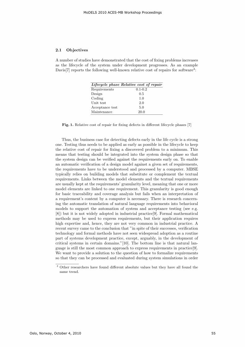
2.1 Objectives
A number of studies have demonstrated that the cost of fixing problems increasesas the lifecycle of the system under development progresses. As an exampleDavis[7] reports the following well-known relative cost of repairs for software4:
Lifecycle phase Relative cost of repair
Requirements 0.1-0.2Design 0.5Coding 1.0Unit test 2.0Acceptance test 5.0Maintenance 20.0
Fig. 1. Relative cost of repair for fixing defects in different lifecycle phases [7]
Thus, the business case for detecting defects early in the life cycle is a strongone. Testing thus needs to be applied as early as possible in the lifecycle to keepthe relative cost of repair for fixing a discovered problem to a minimum. Thismeans that testing should be integrated into the system design phase so thatthe system design can be verified against the requirements early on. To enablean automatic verification of a design model against a given set of requirements,the requirements have to be understood and processed by a computer. MBSEtypically relies on building models that substitute or complement the textualrequirements. Links between the model elements and the textual requirementsare usually kept at the requirements’ granularity level, meaning that one or moremodel elements are linked to one requirement. This granularity is good enoughfor basic traceability and coverage analysis but fails when an interpretation ofa requirement’s content by a computer is necessary. There is research concern-ing the automatic translation of natural language requirements into behavioralmodels to support the automation of system and acceptance testing (see e.g.[8]) but it is not widely adopted in industrial practice[9]. Formal mathematicalmethods may be used to express requirements, but their application requireshigh expertise and, hence, they are not very common in industrial practice. Arecent survey came to the conclusion that ”in spite of their successes, verificationtechnology and formal methods have not seen widespread adoption as a routinepart of systems development practice, except, arguably, in the development ofcritical systems in certain domains.”[10]. The bottom line is that natural lan-guage is still the most common approach to express requirements in practice[9].We want to provide a solution to the question of how to formalize requirementsso that they can be processed and evaluated during system simulations in order
4 Other researchers have found different absolute values but they have all found thesame trend.
MoDELS 2010 ACES-MB Workshop Proceedings
Oslo, Norway, October 4, 2010 55
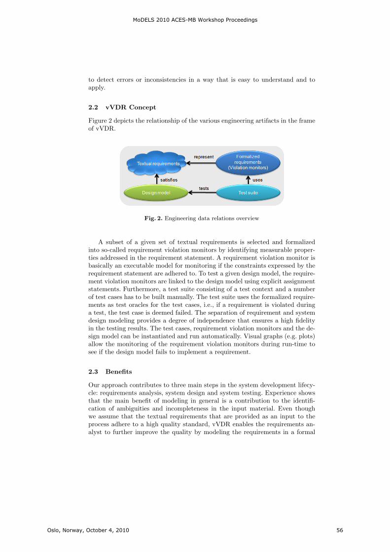
to detect errors or inconsistencies in a way that is easy to understand and toapply.
2.2 vVDR Concept
Figure 2 depicts the relationship of the various engineering artifacts in the frameof vVDR.
Fig. 2. Engineering data relations overview
A subset of a given set of textual requirements is selected and formalizedinto so-called requirement violation monitors by identifying measurable proper-ties addressed in the requirement statement. A requirement violation monitor isbasically an executable model for monitoring if the constraints expressed by therequirement statement are adhered to. To test a given design model, the require-ment violation monitors are linked to the design model using explicit assignmentstatements. Furthermore, a test suite consisting of a test context and a numberof test cases has to be built manually. The test suite uses the formalized require-ments as test oracles for the test cases, i.e., if a requirement is violated duringa test, the test case is deemed failed. The separation of requirement and systemdesign modeling provides a degree of independence that ensures a high fidelityin the testing results. The test cases, requirement violation monitors and the de-sign model can be instantiated and run automatically. Visual graphs (e.g. plots)allow the monitoring of the requirement violation monitors during run-time tosee if the design model fails to implement a requirement.
2.3 Benefits
Our approach contributes to three main steps in the system development lifecy-cle: requirements analysis, system design and system testing. Experience showsthat the main benefit of modeling in general is a contribution to the identifi-cation of ambiguities and incompleteness in the input material. Even thoughwe assume that the textual requirements that are provided as an input to theprocess adhere to a high quality standard, vVDR enables the requirements an-alyst to further improve the quality by modeling the requirements in a formal
MoDELS 2010 ACES-MB Workshop Proceedings
Oslo, Norway, October 4, 2010 56
representation as this forces a detailed analysis of the requirements. The maincontribution of vVDR is to the quality of the system design. The automaticverification of a design model based on the formalized requirements allows thedetection of errors in the system design. The separation of requirements mod-eling and design modeling allow a reuse of the requirements for the verificationof several alternative system designs. Furthermore, even for one design modelthe same requirements violation monitors can be instantiated several times. Asdescribed in [11], the benefits of using a model-based testing approach duringthe system design phase facilitates error tracing and impact assessment in thelater integration and testing stages by providing a seamless traceability from theinitial requirements to test cases and test results. Furthermore, it allows reusingthe artifacts from the engineering stage at the testing stage of the developmentcycle which results in a significant decrease in overall testing effort. By integrat-ing the requirements model in a test bench the test models can also be reusedfor hardware-in-the-loop test setups.
2.4 Related work
In [12] an approach to the incremental consistency checking of dynamically de-finable and modifiable design constraints is presented. Apart from focusing ondesign constraints instead of design requirements which can be argued as be-ing a marginal issue, the main difference to vVDR is that the constraints areexpressed using the design model variables whereas our approach is based ona separation of the requirements and the design model. Only for a specific testcontext are they connected using explicit assignment statements. Additionally,the monitoring of model changes and the evaluation of the defined constraintsis done by a separate ”Model Analyzer Tool” whereas our approach relies onout-of-the-box modeling capabilities. The Behavior Modeling Language (BML)or more specifically the Requirement Behavior Tree technique that is a vitalpart of the BML is another method for formalizing requirements into a formthat can be processed by computers[13][14]. But whereas vVDR relies on a sep-aration between the set of independent requirements that are used to verify adesign model and the building of a design model by the system designer, theBML methodology merges the behavior trees that each represent single require-ments into an overall design behavior tree (DBT). In other words, the transitionfrom the requirements space to the solution space is based on the formalizedrequirements.
3 Background
This chapter provides background information on the graphical modeling nota-tion ModelicaML [15] and its underlying language Modelica [16] which was usedto implement our approach, and introduces the running example that will beused to illustrate the vVDR methodology in Section 4.
MoDELS 2010 ACES-MB Workshop Proceedings
Oslo, Norway, October 4, 2010 57
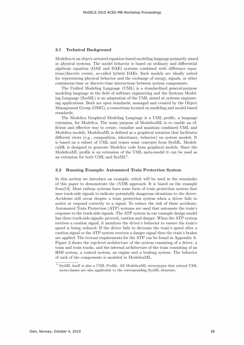
3.1 Technical Background
Modelica is an object-oriented equation-based modeling language primarily aimedat physical systems. The model behavior is based on ordinary and differentialalgebraic equation (OAE and DAE) systems combined with difference equa-tions/discrete events, so-called hybrid DAEs. Such models are ideally suitedfor representing physical behavior and the exchange of energy, signals, or othercontinuous-time or discrete-time interactions between system components.
The Unified Modeling Language (UML) is a standardized general-purposemodeling language in the field of software engineering and the Systems Model-ing Language (SysML) is an adaptation of the UML aimed at systems engineer-ing applications. Both are open standards, managed and created by the ObjectManagement Group (OMG), a consortium focused on modeling and model-basedstandards.
The Modelica Graphical Modeling Language is a UML profile, a languageextension, for Modelica. The main purpose of ModelicaML is to enable an ef-ficient and effective way to create, visualize and maintain combined UML andModelica models. ModelicaML is defined as a graphical notation that facilitatesdifferent views (e.g., composition, inheritance, behavior) on system models. Itis based on a subset of UML and reuses some concepts from SysML. Modeli-caML is designed to generate Modelica code from graphical models. Since theModelicaML profile is an extension of the UML meta-model it can be used asan extension for both UML and SysML5.
3.2 Running Example: Automated Train Protection System
In this section we introduce an example, which will be used in the remainderof this paper to demonstrate the vVDR approach. It is based on the examplefrom[13]. Most railway systems have some form of train protection system thatuses track-side signals to indicate potentially dangerous situations to the driver.Accidents still occur despite a train protection system when a driver fails tonotice or respond correctly to a signal. To reduce the risk of these accidents,Automated Train Protection (ATP) systems are used that automate the train’sresponse to the track-side signals. The ATP system in our example design modelhas three track-side signals: proceed, caution and danger. When the ATP systemreceives a caution signal, it monitors the driver’s behavior to ensure the train’sspeed is being reduced. If the driver fails to decrease the train’s speed after acaution signal or the ATP system receives a danger signal then the train’s brakesare applied. The textual requirements for the ATP can be found in Appendix A.Figure 3 shows the top-level architecture of the system consisting of a driver, atrain and train tracks, and the internal architecture of the train consisting of anHMI system, a control system, an engine and a braking system. The behaviorof each of the components is modeled in ModelicaML.
5 SysML itself is also a UML Profile. All ModelicaML stereotypes that extend UMLmeta-classes are also applicable to the corresponding SysML elements.
MoDELS 2010 ACES-MB Workshop Proceedings
Oslo, Norway, October 4, 2010 58
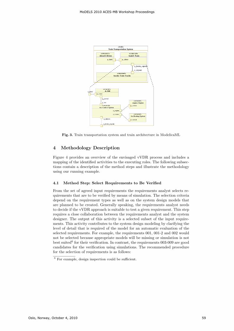
Fig. 3. Train transportation system and train architecture in ModelicaML
4 Methodology Description
Figure 4 provides an overview of the envisaged vVDR process and includes amapping of the identified activities to the executing roles. The following subsec-tions contain a description of the method steps and illustrate the methodologyusing our running example.
4.1 Method Step: Select Requirements to Be Verified
From the set of agreed input requirements the requirements analyst selects re-quirements that are to be verified by means of simulation. The selection criteriadepend on the requirement types as well as on the system design models thatare planned to be created. Generally speaking, the requirements analyst needsto decide if the vVDR approach is suitable to test a given requirement. This steprequires a close collaboration between the requirements analyst and the systemdesigner. The output of this activity is a selected subset of the input require-ments. This activity contributes to the system design modeling by clarifying thelevel of detail that is required of the model for an automatic evaluation of theselected requirements. For example, the requirements 001, 001-2 and 002 wouldnot be selected because appropriate models will be missing or simulation is notbest suited6 for their verification. In contrast, the requirements 003-009 are goodcandidates for the verification using simulations. The recommended procedurefor the selection of requirements is as follows:
6 For example, design inspection could be sufficient.
MoDELS 2010 ACES-MB Workshop Proceedings
Oslo, Norway, October 4, 2010 59

Fig. 4. Methodology overview
– Read a requirement– Decide if this requirement can and shall be evaluated using a simulation
model– Decide if this requirement is complete, unambiguous and testable by using
the kind of design models that are to be created– If yes: Mark this requirement as selected– If no: Skip this requirement
The selected subset of requirements will then be transferred into the modelingtool and used in the subsequent steps.
4.2 Method Step: Formalize Textual Requirements
The second step is to formalize each requirement in order to enable its automaticevaluation during simulations. Consider requirement 006-1: ”If at any time thecontroller calculates a ”caution” signal, it shall, within 0.5 seconds, enable thealarm in the driver cabin.” Based on this statement we can:
– Identify measurable properties included in the requirement statement, i.e.,the reception of a caution signal, the activation of the alarm and the timeframe constant,
– Formalize properties as shown in Fig. 5 and define a requirement violationmonitor as illustrated in Fig. 6.
In order to determine if a requirement is fulfilled the following assumption ismade: A requirement is implemented in and met by a design model as long as
MoDELS 2010 ACES-MB Workshop Proceedings
Oslo, Norway, October 4, 2010 60
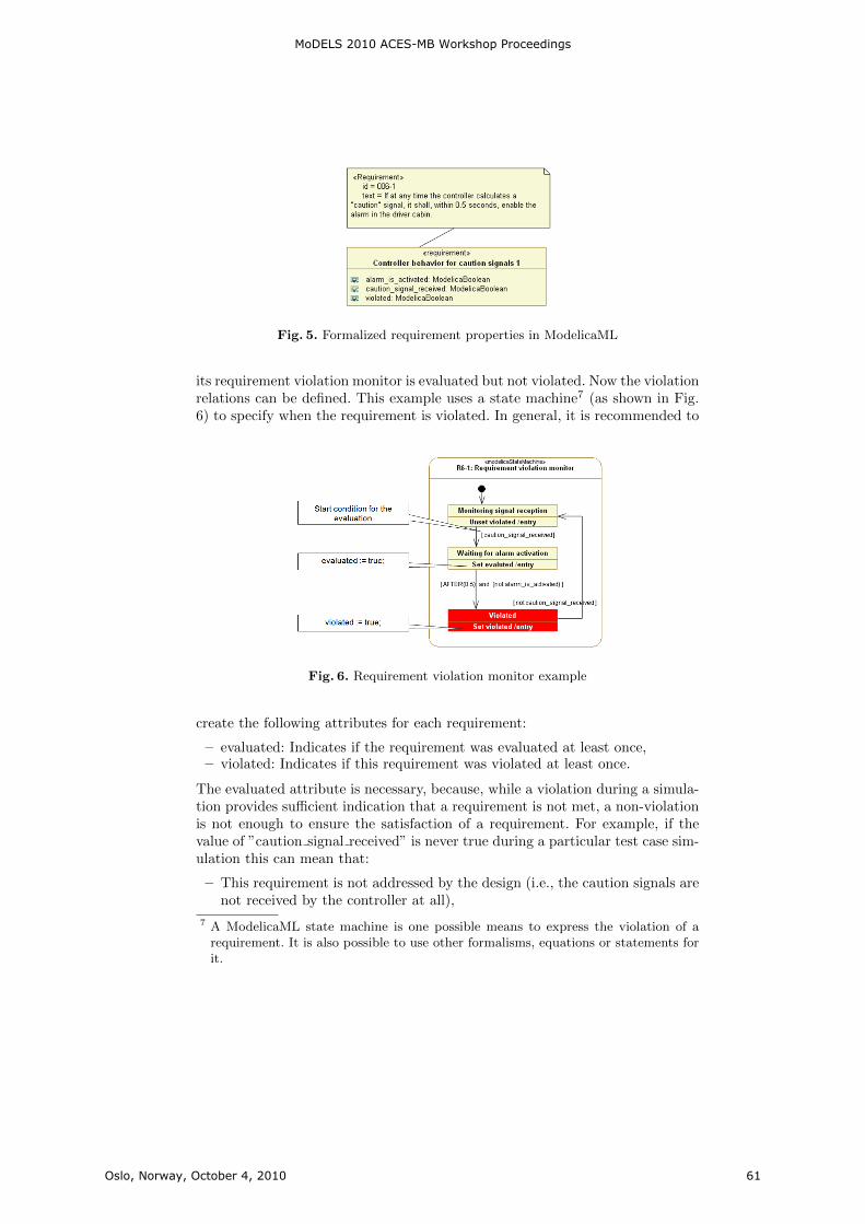
Fig. 5. Formalized requirement properties in ModelicaML
its requirement violation monitor is evaluated but not violated. Now the violationrelations can be defined. This example uses a state machine7 (as shown in Fig.6) to specify when the requirement is violated. In general, it is recommended to
Fig. 6. Requirement violation monitor example
create the following attributes for each requirement:
– evaluated: Indicates if the requirement was evaluated at least once,– violated: Indicates if this requirement was violated at least once.
The evaluated attribute is necessary, because, while a violation during a simula-tion provides sufficient indication that a requirement is not met, a non-violationis not enough to ensure the satisfaction of a requirement. For example, if thevalue of ”caution signal received” is never true during a particular test case sim-ulation this can mean that:
– This requirement is not addressed by the design (i.e., the caution signals arenot received by the controller at all),
7 A ModelicaML state machine is one possible means to express the violation of arequirement. It is also possible to use other formalisms, equations or statements forit.
MoDELS 2010 ACES-MB Workshop Proceedings
Oslo, Norway, October 4, 2010 61
– Or this requirement is not verified by this test case because the test casedoes not provide appropriate stimuli for the design model.
This method step supports the requirements analyst in improving the qualityof the selected requirements by identifying ambiguities or incompleteness issues.For example, the following questions were raised when formalizing the originalinput requirement:
– ”If a caution signal is returned to the ATP controller then the alarm isenabled within the driver’s cab. Furthermore, once the alarm has been en-abled, if the speed of the train is not observed to be decreasing then theATP controller activates the train’s braking system.”
– What does decreasing mean, by which rate?– The driver will need time to react, how much?– The controller cannot activate things instantaneously. How much time is
allowed at the most to pass between the stimuli and the expected result?
Any issues that are identified in this step have to be resolved with the stake-holders and all affected textual requirements have to be updated accordingly.In our example, the updated version of this requirement has been split into twoseparate requirements 006-1 and 006-2.
4.3 Method Step: Select or Create Design Model to Be Verifiedagainst Requirements
The actual system design is not in the scope of this paper. The system designerbuilds a design model for each design alternative that he comes up with8. Sincethe requirements are kept separate from the design alternatives, the same re-quirements can be reused to verify several designs, and the same requirementviolation monitors can be reused in multiple test cases.
4.4 Method Step: Create Test Models, Instantiate Models, LinkRequirement Properties to Design Model Properties
After the formalization of the requirements and the selection of one design modelfor verification, the system tester starts creating test models, defining test casesand linking requirement properties to values inside the design model. The rec-ommended procedure is as follows:
– Define a test model that will contain test cases, a design model, the require-ments and their requirement violation monitors.
– Define test cases for evaluating requirements. One test case can be used forevaluating one or more requirements.
8 For ease of use, the design will normally be modelled in the same notation and thesame tool as the requirements. However, it can be imagined to build interfaces toexecutable models that were built using different modelling notations in differenttools and then subsequently use vVDR to test these models.
MoDELS 2010 ACES-MB Workshop Proceedings
Oslo, Norway, October 4, 2010 62
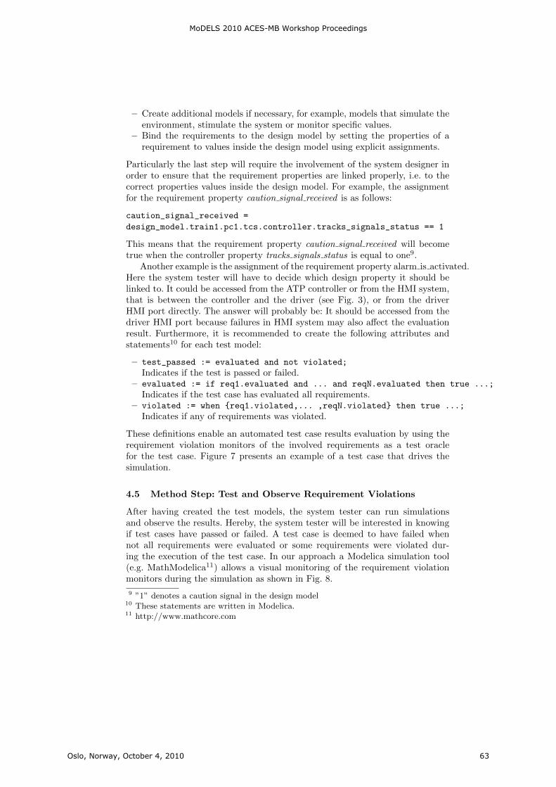
– Create additional models if necessary, for example, models that simulate theenvironment, stimulate the system or monitor specific values.
– Bind the requirements to the design model by setting the properties of arequirement to values inside the design model using explicit assignments.
Particularly the last step will require the involvement of the system designer inorder to ensure that the requirement properties are linked properly, i.e. to thecorrect properties values inside the design model. For example, the assignmentfor the requirement property caution signal received is as follows:
caution_signal_received =
design_model.train1.pc1.tcs.controller.tracks_signals_status == 1
This means that the requirement property caution signal received will becometrue when the controller property tracks signals status is equal to one9.
Another example is the assignment of the requirement property alarm is activated.Here the system tester will have to decide which design property it should belinked to. It could be accessed from the ATP controller or from the HMI system,that is between the controller and the driver (see Fig. 3), or from the driverHMI port directly. The answer will probably be: It should be accessed from thedriver HMI port because failures in HMI system may also affect the evaluationresult. Furthermore, it is recommended to create the following attributes andstatements10 for each test model:
– test_passed := evaluated and not violated;
Indicates if the test is passed or failed.– evaluated := if req1.evaluated and ... and reqN.evaluated then true ...;
Indicates if the test case has evaluated all requirements.– violated := when {req1.violated,... ,reqN.violated} then true ...;
Indicates if any of requirements was violated.
These definitions enable an automated test case results evaluation by using therequirement violation monitors of the involved requirements as a test oraclefor the test case. Figure 7 presents an example of a test case that drives thesimulation.
4.5 Method Step: Test and Observe Requirement Violations
After having created the test models, the system tester can run simulationsand observe the results. Hereby, the system tester will be interested in knowingif test cases have passed or failed. A test case is deemed to have failed whennot all requirements were evaluated or some requirements were violated dur-ing the execution of the test case. In our approach a Modelica simulation tool(e.g. MathModelica11) allows a visual monitoring of the requirement violationmonitors during the simulation as shown in Fig. 8.
9 ”1” denotes a caution signal in the design model10 These statements are written in Modelica.11 http://www.mathcore.com
MoDELS 2010 ACES-MB Workshop Proceedings
Oslo, Norway, October 4, 2010 63
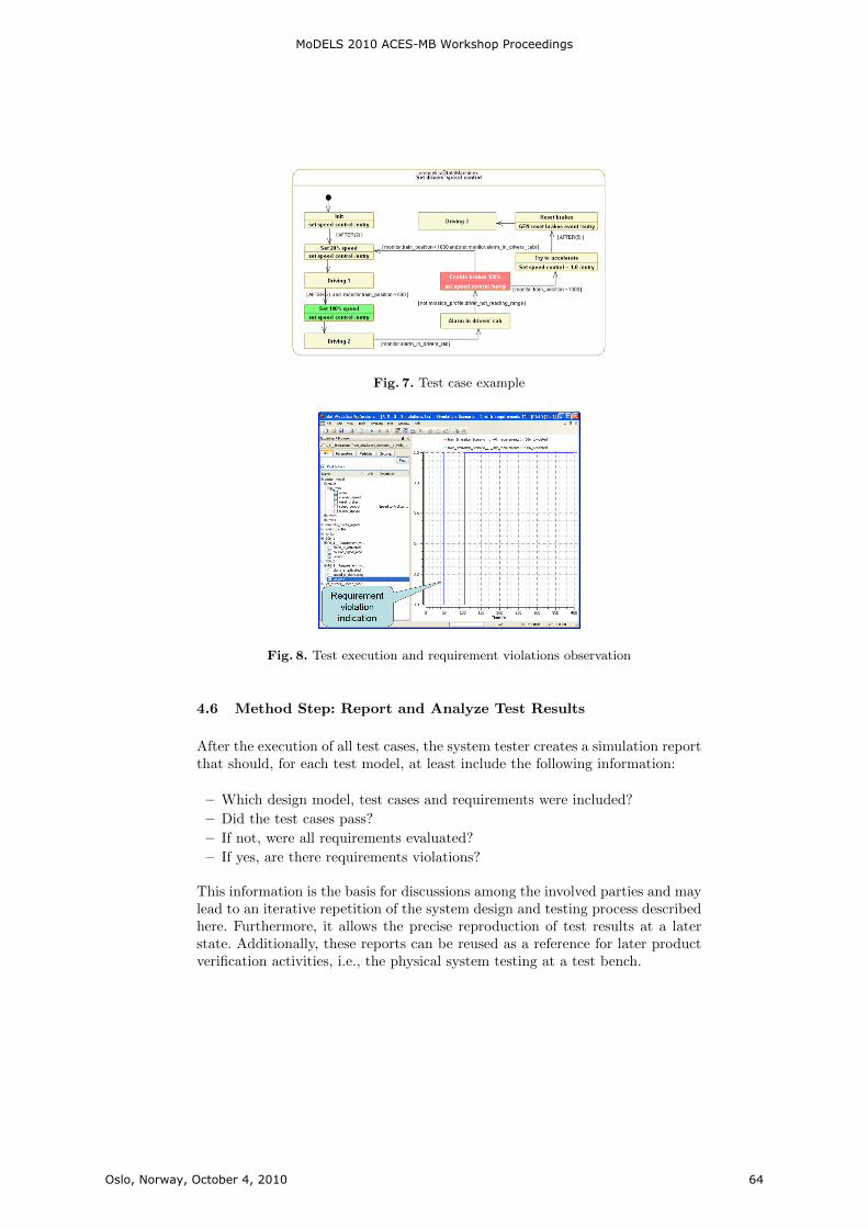
Fig. 7. Test case example
Fig. 8. Test execution and requirement violations observation
4.6 Method Step: Report and Analyze Test Results
After the execution of all test cases, the system tester creates a simulation reportthat should, for each test model, at least include the following information:
– Which design model, test cases and requirements were included?
– Did the test cases pass?
– If not, were all requirements evaluated?
– If yes, are there requirements violations?
This information is the basis for discussions among the involved parties and maylead to an iterative repetition of the system design and testing process describedhere. Furthermore, it allows the precise reproduction of test results at a laterstate. Additionally, these reports can be reused as a reference for later productverification activities, i.e., the physical system testing at a test bench.
MoDELS 2010 ACES-MB Workshop Proceedings
Oslo, Norway, October 4, 2010 64

5 Current Status and Future Directions
The methodology presented in this paper has been successfully applied in severalcase studies. However, the case studies included only a small number of require-ments. In the future, a real-sized case study is planned, i.e., one that containsmore than a hundred requirements to be verified using the vVDR method todetermine the applicability and scalability of this approach. The traceability be-tween requirements and design artifacts is a critical issue in the daily engineeringwork, particularly with regards to change impact analysis. When the system de-sign is evolving or changing then the vVDR approach presented in this papercontributes to an efficient way of verifying the new designs against requirementsby reusing the formalized requirements and test cases for quick and easy regres-sion testing. This is enabled by the separation of requirements and test caseson the one hand and the design models on the other hand. However, it is stillhard to determine the impact of a requirement change on the system design.In order to support impact analysis, a traceability of requirements to designartifacts is necessary at an appropriate level of granularity. For example, partsof a requirement statement, i.e.,. single words, should be linked to the differentdesign model elements that they are referring to. Moreover, an effective visual-ization and dependencies exploration is necessary in order to enable an efficienthandling of changes. A model-based development approach enables an effectiveand efficient reporting on and monitoring of the requirements implementation.For example, a bidirectional traceability between requirement and design allowsthe determination of the system development status and supports project riskmanagement and planning. While the test cases for our running example can beeasily derived directly from the input requirements, manual test case generationbecomes an increasingly tedious task for real-life specifications with hundredsof requirements. Model-based testing provides methods for automated test casegeneration some of which already work on UML models[17] and look promis-ing to be adapted to vVDR. Requirements traceability, a higher test automationthrough adaptation of model-based testing techniques as well as reporting topicsare subject to our future work.
6 Conclusion
This paper presents a method for the virtual verification of system designsagainst system requirements by means of simulation. It provides a detailed de-scription of all method steps and illustrates them using an example case studythat was implemented using ModelicaML. It points out that this method stronglydepends on the design models that are planned to be created and that not alltype of requirements can be evaluated using this method. In the vVDR ap-proach, formalized requirements, system design and test cases are defined inseparate models and can be reused and combined into test setups in an efficientmanner. In doing so, a continuous evaluation of requirements along the systemdesign evolution can be done starting in the early system design stages. This ap-proach enables an early detection of errors or inconsistencies in system design,
MoDELS 2010 ACES-MB Workshop Proceedings
Oslo, Norway, October 4, 2010 65

as well as of inconsistent, not feasible or conflicting requirements. Moreover,the created artifacts can be reused for later product verification (i.e., physicaltesting) activities.
References
1. C. Haskins, Ed., Systems Engineering Handbook: A guide for system life cycleprocesses and activities. INCOSE, 2006.
2. D. Gause and G. Weinberg, Exploring requirements: quality before design. DorsetHouse Pub, 1989.
3. P. Loucopoulos and V. Karakostas, System requirements engineering. McGraw-Hill, Inc. New York, NY, USA, 1995.
4. E. Hull, K. Jackson, and J. Dick, Requirements engineering. Springer Verlag,2005.
5. J. Estefan, “Survey of model-based systems engineering (MBSE) methodologies,”Incose MBSE Focus Group, vol. 25, 2007.
6. P. Helle, A. Mitschke, C. Strobel, W. Schamai, A. Riviere, and L. Vincent, “Im-proving Systems Specifications - A Method Proposal,” in Proceedings of CSER2008 Conference, April 4-5 2008, Los Angeles, CA, 2010.
7. A. Davis, Software requirements: objects, functions, and states. Prentice-Hall, Inc.Upper Saddle River, NJ, USA, 1993.
8. V. A. d. Santiago Junior, Natural language requirements: automating model-basedtesting and analysis of defects. Sao Jose dos Campos: Instituto Nacional dePesquisas Espaciais, 2010.
9. L. Mich, M. Franch, and P. Novi Inverardi, “Market research for requirementsanalysis using linguistic tools,” Requirements Engineering, vol. 9, no. 2, pp. 151–151, 2004.
10. J. Woodcock, P. Larsen, J. Bicarregui, and J. Fitzgerald, “Formal methods: Prac-tice and experience,” ACM Computing Surveys (CSUR), vol. 41, no. 4, pp. 1–36,2009.
11. P. Helle and W. Schamai, “Specification model-based testing in the avionic domain- Current status and future directions,” in Proceedings of the Sixth Workshop onModel-Based Testing 2010, Paphos, Cyprus, 2010.
12. I. Groher, A. Reder, and A. Egyed, “Incremental Consistency Checking of Dy-namic Constraints,” Fundamental Approaches to Software Engineering, pp. 203–217, 2010.
13. T. Myers, P. Fritzson, and R. Dromey, “Seamlessly Integrating Software & Hard-ware Modelling for Large-Scale Systems,” in 2nd International Workshop onEquation-Based Object-Oriented Languages and Tools, Paphos, Cyprus, 2008.
14. D. Powell, “Requirements evaluation using behavior trees-findings from industry,”in Australian Software Engineering Conference (ASWEC07), 2007.
15. W. Schamai, P. Fritzson, C. Paredis, and A. Pop, “Towards Unified System Mod-eling and Simulation with ModelicaML: Modeling of Executable Behavior Us-ing Graphical Notations,” in Proc. of the 7th International Modelica Conference,Como, Italy, 2009.
16. P. Fritzson, Principles of object-oriented modeling and simulation with Modelica2.1. Wiley-IEEE Press, 2004.
17. M. Prasanna, S. Sivanandam, R. Venkatesan, and R. Sundarrajan, “A survey onautomatic test case generation,” Academic Open Internet Journal, vol. 15, 2005.
MoDELS 2010 ACES-MB Workshop Proceedings
Oslo, Norway, October 4, 2010 66
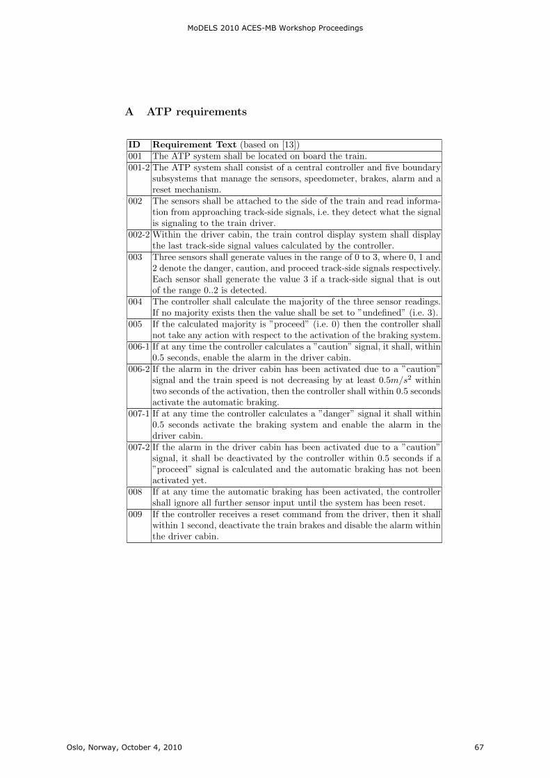
A ATP requirements
ID Requirement Text (based on [13])001 The ATP system shall be located on board the train.001-2 The ATP system shall consist of a central controller and five boundary
subsystems that manage the sensors, speedometer, brakes, alarm and areset mechanism.
002 The sensors shall be attached to the side of the train and read informa-tion from approaching track-side signals, i.e. they detect what the signalis signaling to the train driver.
002-2 Within the driver cabin, the train control display system shall displaythe last track-side signal values calculated by the controller.
003 Three sensors shall generate values in the range of 0 to 3, where 0, 1 and2 denote the danger, caution, and proceed track-side signals respectively.Each sensor shall generate the value 3 if a track-side signal that is outof the range 0..2 is detected.
004 The controller shall calculate the majority of the three sensor readings.If no majority exists then the value shall be set to ”undefined” (i.e. 3).
005 If the calculated majority is ”proceed” (i.e. 0) then the controller shallnot take any action with respect to the activation of the braking system.
006-1 If at any time the controller calculates a ”caution” signal, it shall, within0.5 seconds, enable the alarm in the driver cabin.
006-2 If the alarm in the driver cabin has been activated due to a ”caution”signal and the train speed is not decreasing by at least 0.5m/s2 withintwo seconds of the activation, then the controller shall within 0.5 secondsactivate the automatic braking.
007-1 If at any time the controller calculates a ”danger” signal it shall within0.5 seconds activate the braking system and enable the alarm in thedriver cabin.
007-2 If the alarm in the driver cabin has been activated due to a ”caution”signal, it shall be deactivated by the controller within 0.5 seconds if a”proceed” signal is calculated and the automatic braking has not beenactivated yet.
008 If at any time the automatic braking has been activated, the controllershall ignore all further sensor input until the system has been reset.
009 If the controller receives a reset command from the driver, then it shallwithin 1 second, deactivate the train brakes and disable the alarm withinthe driver cabin.
MoDELS 2010 ACES-MB Workshop Proceedings
Oslo, Norway, October 4, 2010 67

Approach for Iterative Validation of AutomotiveEmbedded Systems
Gereon Weiss, Marc Zeller, Dirk Eilers and Rudi Knorr
Fraunhofer Institute for Communication Systems ESK,Hansastr. 32, 80686 Munich, Germany,
{gereon.weiss, marc.zeller, dirk.eilers, rudi.knorr}@esk.fraunhofer.de,http://www.esk.fraunhofer.de
Abstract. Architecture description languages (ADLs) allow specifyingsystem information in architecture models. These are generally usedfor capturing early design decisions concerning system or software de-velopment. Therefore, ADLs can be utilized for an early and iterativevalidation of the modelled system. With EAST-ADL an automotive-specific ADL is defined which allows describing an automotive system atdifferent layers of abstraction targeting AUTOSAR systems. SystemCis an executable system modelling and simulation language which per-mits Hardware/Software-Co-Design. With the Transaction-Level Model-ing (TLM) methodology the description of different layers of abstractionin SystemC is enabled. This work addresses the early validation of auto-mobile electronic systems by providing a transformation of EAST-ADLmodels to SystemC at different layers of abstraction. This allows spe-cific analysis with Hardware/Software Co-Simulation iteratively in thedevelopment process. The proposed approach is realized in a tool-chainand demonstrated by a typical automotive use case. Hence, we show thepotential of an early validation of system and software designs based onarchitecture models.
1 Introduction
Model-driven design has been successfully introduced into diverse applicationareas for abstracting from complex systems. With Architecture Description Lan-guages (ADLs) a solution is provided to capture design information on a highlevel of abstraction [1]. Various model-based tools exist which model the distinctbehaviour of functions. ADLs allow to model the interaction of such functionson a system level describing the software and system architecture. An explicitmodelling of layers of abstraction of the system provides the possibility to ab-stract from the system implementation at different points of view. Thus, specialattention can be given to specific details of interest at the particular level. Asarchitecture models include system information they can be used for a valida-tion of the architecture even in early design phases. Approaches integrating wellwith the tool flow enable the validation in iterative steps as the system is refined.This permits early feedback to the development avoiding changes because of lateidentified design problems.
MoDELS 2010 ACES-MB Workshop Proceedings
Oslo, Norway, October 4, 2010 69

2
The automotive domain poses an area with complex interconnected embed-ded systems. Domain-specific modelling languages have been introduced to re-alize distinct functional behaviour. As this alleviates the development of sin-gle applications, with the more interacting functionality a more course-grainedview on the overall system is needed. EAST-ADL [2] as a system level viewfor the automotive domain allows abstracting from the automotive electronicsystem at different levels. At implementation level the AUTomotive Open Sys-tem ARchitecture (AUTOSAR) [3] meta-model is adopted enabling a well de-fined integration in present development methodologies. For the simulation andvalidation of hardware/software systems the system-modelling language Sys-temC [4] was developed. It incorporates a simulation kernel and structures forHardware/Software-Co-Design. With Transaction-Level Modeling (TLM) [5] dif-ferent levels of abstraction can be modelled in SystemC. Additionally, a subsetof SystemC is synthesizable, e.g. for FPGA implementations.
Since the application of SystemC for a simulation-based validation of au-tomotive electronic systems is a promising approach for design exploration andhardware sizing, its integration within the architecture design has to be pursued.Therefore, we introduce in this work an adoption of SystemC in the develop-ment process with architecture descriptions based on EAST-ADL. An automatictransformation on the different layers of abstraction of EAST-ADL to SystemCis presented in this paper which enables a simulation-based validation. Thereby,architecture models can be iteratively refined and improved in the developmentprocess.
This paper is structured as follows. In the next section related work to ourapproach is described. Afterwards, in Section 3 and 4 the concepts and mainlanguage elements of EAST-ADL and SystemC are presented. In Section 5 weintroduce at first a mapping of the layers of abstraction of both languages.Subsequently, we detail the transformation of language artefacts of EAST-ADLto SystemC. A case study within the automotive domain shows the applicabilityof our approach in Section 6. This paper is concluded and an outlook on ourfuture work is given in the last section.
2 Related Work
In this section we briefly describe related work to our approach with the focus onarchitecture descriptions and validation by simulation. The Architecture Anal-ysis and Design Language (AADL) [6] was initially developed for the avionicsdomain but addresses generally the modelling of embedded real-time systems.It provides a textual and graphical notation for the architecture design of hard-ware and software components. Several approaches focus on the generation fromAADL models for simulations [7] [8].
EAST-ADL (cp. Section 3) is a specific ADL for the automotive domain.It features defined layers of abstraction of the system and an orthogonal singleenvironment model. The realization of the implementation layer of EAST-ADLis provided by AUTOSAR. As EAST-ADL was chosen as automotive ADL for
MoDELS 2010 ACES-MB Workshop Proceedings
Oslo, Norway, October 4, 2010 70
3
this work it is more comprehensively described below. AUTOSAR (AutomotiveOpen System Architecture) [3] is a widely spread software architecture in theautomotive domain. Instead of the traditionally ECU (Electronic Control Unit)centric development it focuses on the entire system and separates functional-ity from infrastructure. AUTOSAR provides well-defined interfaces for softwarecomponents and layers of abstraction for hardware and infrastructure.
The Component Language (COLA) [9] is defined by formal syntax and se-mantics based upon synchronous dataflow. It also allows the hierarchical de-composition of the system. Even though it addresses the general modelling ofembedded systems, it is evaluated for automotive case studies. A transformationto SystemC for an early design validation has also been carried out [10].
An approach to integrate virtual prototyping in the development process ofvehicles is presented in [11]. In this work a mapping of Automotive Open Sys-tem Architecture (AUTOSAR) [3] components to an equivalent SystemC modelat different levels of granularity is outlined. Due to this mapping it is possi-ble to co-simulate AUTOSAR-conform automotive software systems at differentstages of the development process. In [12] and [13] a co-simulation approachfor automotive embedded systems is described. The aim of this SystemC basedapproach is to enhance the diagnosis ability of the system. It integrates the func-tional model and the hardware specification with multi levels of granularity. In[14] and [15] a methodology for embedded systems based on SystemC TLM [5] isproposed. This methodology enables the rapid prototyping of embedded systemsfor functional validation and performance evaluation in early stages of the designprocess. Stepwise refinement of the system model allows the co-simulation at anuntimed, cycle approximate or cycle accurate level.
3 EAST-ADL
EAST-ADL (Electronics Architecture and Software Technology - ArchitectureDescription Language) [2] was initially developed and refined during severalresearch projects as an automotive domain-specific ADL. Its main purpose isthe model-based management of all engineering information in a single model.EAST-ADL is used at the design stage in the automotive domain. It is an ar-chitecture description language which supports different abstract views on anautomotive electronic architecture. EAST-ADL integrates the component-basedarchitecture of AUTOSAR [3], making it an AUTOSAR compliant architecturedescription language. The language is defined as a UML Profile [16] allowing aconsistent description of the architecture with UML. The model of the completesystem is separated into different layers of abstraction as shown in Figure 1.
The upper modelling layers provide an architecture independent system de-scription which can be mapped to the AUTOSAR architecture description onthe implementation layer. Orthogonal to the horizontal layers is the Environ-ment Model as it exhibits no abstraction layers. It encapsulates plant models,i.e. models of the behaviour of the vehicle and its non-electronic systems. Func-
MoDELS 2010 ACES-MB Workshop Proceedings
Oslo, Norway, October 4, 2010 71
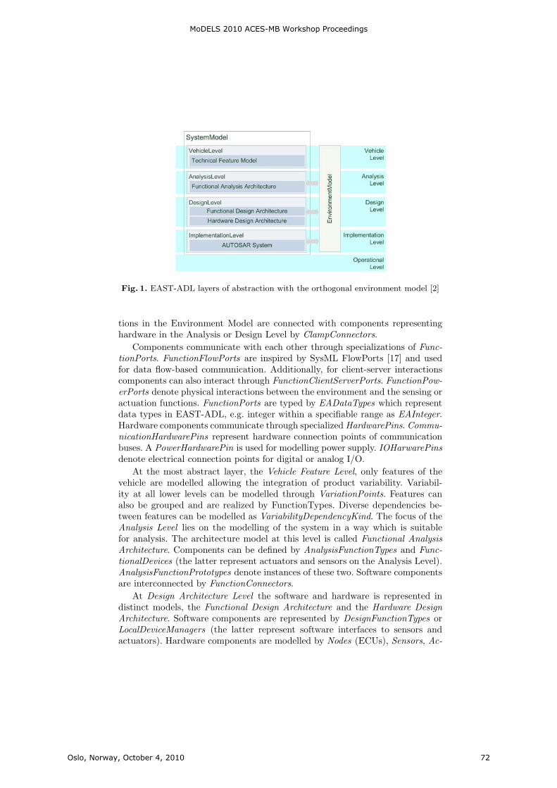
4
Fig. 1. EAST-ADL layers of abstraction with the orthogonal environment model [2]
tions in the Environment Model are connected with components representinghardware in the Analysis or Design Level by ClampConnectors.
Components communicate with each other through specializations of Func-tionPorts. FunctionFlowPorts are inspired by SysML FlowPorts [17] and usedfor data flow-based communication. Additionally, for client-server interactionscomponents can also interact through FunctionClientServerPorts. FunctionPow-erPorts denote physical interactions between the environment and the sensing oractuation functions. FunctionPorts are typed by EADataTypes which representdata types in EAST-ADL, e.g. integer within a specifiable range as EAInteger.Hardware components communicate through specialized HardwarePins. Commu-nicationHardwarePins represent hardware connection points of communicationbuses. A PowerHardwarePin is used for modelling power supply. IOHarwarePinsdenote electrical connection points for digital or analog I/O.
At the most abstract layer, the Vehicle Feature Level, only features of thevehicle are modelled allowing the integration of product variability. Variabil-ity at all lower levels can be modelled through VariationPoints. Features canalso be grouped and are realized by FunctionTypes. Diverse dependencies be-tween features can be modelled as VariabilityDependencyKind. The focus of theAnalysis Level lies on the modelling of the system in a way which is suitablefor analysis. The architecture model at this level is called Functional AnalysisArchitecture. Components can be defined by AnalysisFunctionTypes and Func-tionalDevices (the latter represent actuators and sensors on the Analysis Level).AnalysisFunctionPrototypes denote instances of these two. Software componentsare interconnected by FunctionConnectors.
At Design Architecture Level the software and hardware is represented indistinct models, the Functional Design Architecture and the Hardware DesignArchitecture. Software components are represented by DesignFunctionTypes orLocalDeviceManagers (the latter represent software interfaces to sensors andactuators). Hardware components are modelled by Nodes (ECUs), Sensors, Ac-
MoDELS 2010 ACES-MB Workshop Proceedings
Oslo, Norway, October 4, 2010 72
5
tuators and LogicalBusses. They are interconnected with HardwareConnectors.A LogicalBus represents the allocation target for FunctionConnectors, i.e. ex-changed data in the Functional Design Architecture. Nodes are the allocationtargets for DesignFunctionTypes and LocalDeviceManagers. HardwareCompo-nentPrototypes are properties typed with the above mentioned hardware typesrepresenting instances.
On the transition from the Design Level to the Implementation Level a map-ping to the AUTOSAR meta-model is foreseen. Therefore, modelling artefactson this level are compliant to the AUTOSAR specification in version 3 [3]. TheOperational Level refers to the deployed and running system and is not mod-elled for this reason. Behaviour is not explicitly considered in EAST-ADL. Itcan either be modelled externally (e.g. in domain-specific tools like Matlab or ina platform-specific programming language like C/C++) or internally in EAST-ADL utilizing UML behaviour modelling (like Activity Diagrams or Statecharts).As we have introduced EAST-ADL and its layers of abstraction, in the next sec-tion the language and a methodology to abstract different levels of SystemC areoutlined.
4 SystemC - Transaction-Level Modeling
SystemC is a standardized system modelling and simulation language whichsupports Hardware/Software-Co-Design and Co-Simulation. It is standardisedand promoted by the Open SystemC Initiative (OSCI) [18] and has been ap-proved by the IEEE Standards Association as IEEE 1666-2005 [4]. Based onthe wide-spread programming language C++, SystemC provides artefacts tosimulate concurrent processes and an event-driven simulation kernel. Although,having semantic similarities to hardware description languages (like VHDL andVerilog), SystemC can be used to model the holistic system using plain C++.
A SystemC model usually consists of several modules (sc module) which maybe organized hierarchically. Computation in SystemC is modelled by so-calledprocesses which are enclosed in modules. Processes are inherently concurrent.Communication from inside a module to the outside - mostly other modules- is realized via ports (sc port). These are connected to channels (sc channel)by SystemC interfaces (sc interface). This enables the modelling of complexcommunication structures (e.g. FIFO or network bus) in SystemC.
With SystemC new models can be connected easily to existing hardwareor functional models - either in platform-specific programming languages likeC/C++ or domain-specific modelling tools, e.g. Matlab/Simulink within theautomotive domain. Furthermore, it is possible to include any existing C orC++ library in the own system model. Thus, suppliers, for example within theautomotive domain, can interchange pre-compiled hardware or software moduleswith other suppliers or car manufacturers and do not need to disclose theirintellectual property.
To integrate Hardware/Software Co-Simulation effectively in the develop-ment process of networked embedded systems, a stepwise refinement of the mod-
MoDELS 2010 ACES-MB Workshop Proceedings
Oslo, Norway, October 4, 2010 73
6
els is necessary. This can be realized by using SystemC because it implements atop-down design process according to the Transaction-Level Modeling (TLM) [5]methodology. TLM is a methodology used for modelling digital systems whichseparates the details of communication among computational components fromthe details of the computational components. Details of communication or com-putation can be hidden in early stages of the design and added later. There-fore, communication mechanisms such as interconnection buses are modelledas sc channels which can be accessed by sc modules using SystemC interfaceclasses. Transaction requests take place by calling interface functions of thesechannels. Low-level details of the communication process are encapsulated bythe sc interfaces. By this, the refinement of computation is separated from therefinement of communication. This approach enables the evaluation of differentinterconnection systems without having to re-implement the computation mod-els that interact with any of the buses, because the computation models interactwith the communication model through the common interfaces.
The OSCI Transaction Level Working Group has defined different levels ofabstraction for TLM [19]. The most abstract level is denoted as CommunicatingProcesses (CP). At this level the behaviour of the system is partitioned intoparallel processes that exchange complex, high-level data structures throughpoint-to-point connections. Communicating Processes with Time (CPT) is iden-tical with CP, but introduces timing annotations. The next more detailed level,Programmers View (PV), is much more architecture-specific. Bus models are in-stantiated to act as transport mechanisms between the model components andsome arbitration of the communication infrastructure is applied. ProgrammersView with Time (PVT) is functionally identical with PV but is annotated withmore accurate timing information than CPT. At the level called Cycle Callable(CC) computation models are clocked and all timing annotations are accurateto the level of individual clock cycles. Communication models are fully protocolcompliant. After introducing the abstraction levels of SystemC TLM we intro-duce in the next section our approach of mapping the architecture descriptionof EAST-ADL to SystemC TLM.
5 Simulation-based Validation With Architecture Models
Architecture models capture information of the system development and allow asimulation-based validation. As described in Section 3 EAST-ADL enables themodelling of a system on different layers of abstraction. With TLM differentlevels for abstracting the modelled system are introduced in SystemC (cp. theprevious Section 4). A combination of this ADL with the SystemC allows for aniterative design with early feedback on the models through Hardware/Software-Co-Simulation. For combining the advantages of an ADL and of simulations, thelevels of abstraction have to be aligned. Thus, in the following we motivate amapping of the levels of abstraction of EAST-ADL to the SystemC TLM levelsas depicted in Figure 2.
MoDELS 2010 ACES-MB Workshop Proceedings
Oslo, Norway, October 4, 2010 74
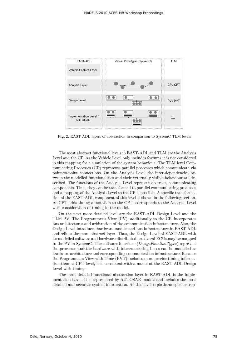
7
Fig. 2. EAST-ADL layers of abstraction in comparison to SystemC TLM levels
The most abstract functional levels in EAST-ADL and TLM are the AnalysisLevel and the CP. As the Vehicle Level only includes features it is not consideredin this mapping for a simulation of the system behaviour. The TLM level Com-municating Processes (CP) represents parallel processes which communicate viapoint-to-point connections. On the Analysis Level the inter-dependencies be-tween the modelled functionalities and their externally visible behaviour are de-scribed. The functions of the Analysis Level represent abstract, communicatingcomponents. Thus, they can be transformed to parallel communicating processesand a mapping of the Analysis Level to the CP is possible. A specific transforma-tion of the EAST-ADL component of this level is shown in the following section.As CPT adds timing annotation to the CP it corresponds to the Analysis Levelwith consideration of timing in the model.
On the next more detailed level are the EAST-ADL Design Level and theTLM PV. The Programmer’s View (PV), additionally to the CP, incorporatesbus architectures and arbitration of the communication infrastructure. Also, theDesign Level introduces hardware models and bus infrastructure in EAST-ADLand refines the more abstract layer. Thus, the Design Level of EAST-ADL withits modelled software and hardware distributed on several ECUs may be mappedto the PV in SystemC. The software functions (DesignFunctionTypes) representthe processes and the hardware with interconnecting buses can be modelled ashardware architecture and corresponding communication infrastructure. Becausethe Programmers View with Time (PVT) includes more precise timing informa-tion than at CPT level, it is consistent with a model at the EAST-ADL DesignLevel with timing.
The most detailed functional abstraction layer in EAST-ADL is the Imple-mentation Level. It is represented by AUTOSAR models and includes the mostdetailed and accurate system information. As this level is platform specific, rep-
MoDELS 2010 ACES-MB Workshop Proceedings
Oslo, Norway, October 4, 2010 75
8
resents a specific implementation and provides the necessary detailed informa-tion for a cycle-accurate simulation, it can be transformed to the TLM CycleCallable Level (CC). The latter is cycle accurate with respect to individual clockcycles and thus well suited for simulating time-accurate AUTOSAR models. Thealigned levels of abstraction as shown in Figure 2 include specific artefacts of themodelling languages which need to be transformed for a mapping. These are inthe focus of the next subsection.
5.1 Mapping of EAST-ADL Artefacts to SystemC TLM
In the previous section we pointed out the general commonalities of the differ-ent levels of abstraction of EAST-ADL and SystemC. For an integration of avalidation in SystemC the single artefacts of EAST-ADL have to be mappedto SystemC language elements. In the following we address such a mapping forthe structural parts of the upper two functional levels of EAST-ADL the Anal-ysis Level and the Design Level. As the Implementation Level is realized withAUTOSAR models, a mapping does not relate to EAST-ADL but to the AU-TOSAR meta-model. Thus, a simulation with SystemC TLM can be realized byan approach based on AUTOSAR software components as presented in [11]. Bythis transformation particular emphasis has to be put on the semantic mappingand preservation of the defined artefacts. The structure of the model is preservedin the transformation. Thus, a tracing of the model artefacts to the SystemCcode-level artefacts is possible, with the drawback of not optimized code. Thisalso enables the feedback from the simulation to the respective model elements.
The following mapping focuses on the structural parts of the languages asthe behaviour is not modelled explicitly in EAST-ADL (s. Section 3). Timingdefinitions have been integrated as non-funtional properties in the last version ofEAST-ADL. As this relates to the non-functional property timing, it does not de-fine the functional behaviour. An integration of the EAST-ADL timing semantics(Timing Augmented Description Language [20]) is currently in progress as futurework. Only references to behaviour specified externally (e.g. UML behaviour orMatlab/Simulink Models) are included in the architecture model. Thus, the be-haviour can be mapped directly to SystemC. For realizing the mapping of thebehaviour off-the-shelf C/C++ code generators for the referenced behaviour canbe used, e.g. TargetLink or UML Statechart generators. The generated platformcode can be integrated as behaviour of SystemC Modules (sc modules).
The orthogonal Environment Model can be represented by a single sc modulewhich includes the environment behaviour as sub modules, e.g. as code gener-ated from a Matlab/Simulink model. ClampConnectors are specific elementsfor interfacing environment components with the horitontal Functional AnalysisArchitecture and the Functional Design Architecture. This connections can berealized with sc channels and sc interfaces in SystemC.
In the previous section the general relation of the Analysis Level of EAST-ADL and the CP level of TLM has been explained. For a specific mapping ofthese levels rules for transforming the EAST-ADL artefacts to SystemC elementshave to be defined. As shown in Figure 3 EAST-ADL components can generally
MoDELS 2010 ACES-MB Workshop Proceedings
Oslo, Norway, October 4, 2010 76
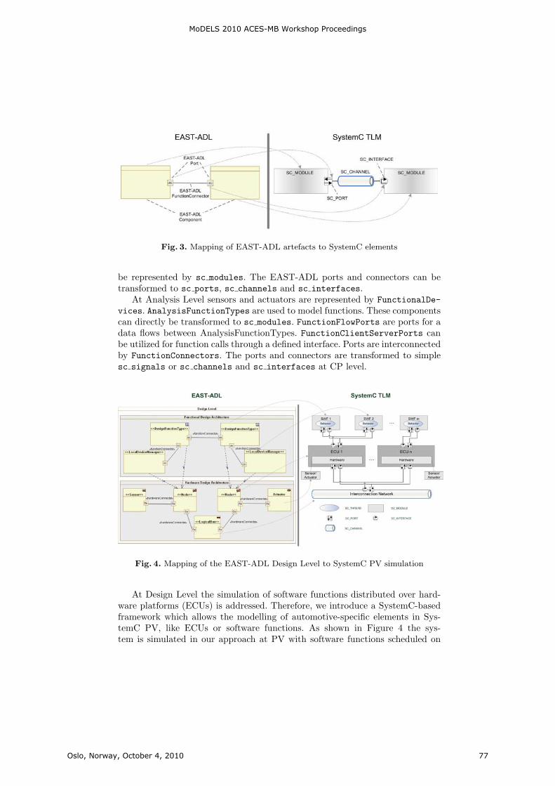
9
Fig. 3. Mapping of EAST-ADL artefacts to SystemC elements
be represented by sc modules. The EAST-ADL ports and connectors can betransformed to sc ports, sc channels and sc interfaces.
At Analysis Level sensors and actuators are represented by FunctionalDe-vices. AnalysisFunctionTypes are used to model functions. These componentscan directly be transformed to sc modules. FunctionFlowPorts are ports for adata flows between AnalysisFunctionTypes. FunctionClientServerPorts canbe utilized for function calls through a defined interface. Ports are interconnectedby FunctionConnectors. The ports and connectors are transformed to simplesc signals or sc channels and sc interfaces at CP level.
Fig. 4. Mapping of the EAST-ADL Design Level to SystemC PV simulation
At Design Level the simulation of software functions distributed over hard-ware platforms (ECUs) is addressed. Therefore, we introduce a SystemC-basedframework which allows the modelling of automotive-specific elements in Sys-temC PV, like ECUs or software functions. As shown in Figure 4 the sys-tem is simulated in our approach at PV with software functions scheduled on
MoDELS 2010 ACES-MB Workshop Proceedings
Oslo, Norway, October 4, 2010 77

10
ECUs communicating via interconnecting buses. The respective components inSystemC are specialized sc modules. For example, a DesignFunctionType ismapped to a software function (SWF) defined in the framework which is derivedfrom a sc module.
A general mapping of the EAST-ADL elements at Design Level to SystemCis depicted in Figure 4. The Design Level consists of software and hardwaremodels. DesignFunctionTypes represent software functions. Software interact-ing with hardware sensors and actuators are modelled as LocalDeviceMana-gers. The hardware components at this level are Sensors, Actuators andLocalBuses. These components can be transformed to sc modules at PV levelas mentioned above. HardwarePorts and HardwareConnectors are transformedto sc channels and sc interfaces level. An extract of the main EAST-ADL
Table 1. Overview of the mapping of core elements of EAST-ADL onto SystemC TLMelements
EAST-ADL SystemC TLM
AnalysisFunctionType sc module
FunctionalDevice sc module
FunctionConnector sc channel,sc interface
DesignFunctionType sc module
LocalDeviceManager sc module
HardwareConnector sc channel,sc interface
Node sc module
Sensor sc module
Actuator sc module
LogicalBus sc module
FunctionFlowPort sc port
FunctionClientServerPort sc channel,sc interface
HardwarePort sc port
elements and their corresponding SystemC elements is given in Table 1. In thenext section these transformation rules are applied in an automobile case studyemphasizing their applicability for enabling an iterative validation within thedevelopment process based on an architecture model.
6 Case Study
The use of architecture models for a validation by simulation is evaluated in acase study for the previously described transformation of EAST-ADL to Sys-temC. Thereby, the focus of this work lies more on the structural mapping andgeneration of simulations than on the validation or analysis itself.
The afore introduced transformation of EAST-ADL models to executableSystemC models has been realized in a prototypical tool-chain. For evaluationpurposes an automotive case study [21] has been modelled in EAST-ADL and
MoDELS 2010 ACES-MB Workshop Proceedings
Oslo, Norway, October 4, 2010 78

11
transformed to SystemC simulations. The use case is within the so-called bodydomain of an automobile and consists of the four features exterior light, directionindication, central door locking and keyless door entry.
Fig. 5. Composite diagram of the use case at Analysis Level
The exterior light feature allows controlling the front and rear lights of thevehicle. The lights can be switched on/off manually or automatically throughdarkness or rain detected by the rain/light sensor. These inputs are interpretedby the function exterior light control which controls the light units (front andrear). For the direction indication a direction indication switch can be used tosignal the turning direction. With the hazard light switch, risky driving situa-tions can be signalled to other road users. Therefore, the direction indicationmaster control informs the direction indication front and rear controls aboutthe designated status of the direction indication lights. These turn the directionindication lights on or off in the front and rear light units. Central door lock-ing allows locking and unlocking all doors simultaneously by using the key inthe lock or by radio transmission. A radio receiver signals the information tothe central door locking control. This function flashes the direction indicationlights for a feedback to the driver and controls the four door locks of the car.An additional feature to the un-/locking of an automobile is the keyless entry. Adriver can approach his car with the key in his pocket and the doors will unlockautomatically. It can be locked by simply pressing a button on the door handle.Antenna components detect the key in the surrounding and inform the centraldoor locking function which in turn unlocks the doors. With respect to the in-teraction with exterior light (which gives feedback via the direction indicationlights), it does not make any difference whether the doors have been unlockedin a standard way or via the keyless entry. In the following a realization of these
MoDELS 2010 ACES-MB Workshop Proceedings
Oslo, Norway, October 4, 2010 79

12
features at Analysis Level and Design Level of EAST-ADL is described with itscorresponding SystemC implementation.
At Analysis Level this use case is modelled in EAST-ADL by the Functi-onalDevices KeylessEntryController, CentralDoorLockingController, Di-rectionIndicationMasterController, DirectionIndicationFrontControl-ler, DirectionIndicationRearController and ExteriorLightController ascan be derived from Figure 5. The behaviour of these functionalities is describedas opaque behaviour of the components (C++ source code). Additionally, be-haviour can be modelled with straight-forward UML Statecharts providing aUML based behaviour specification. Communication is designed as data flowrepresented by FunctionFlowPorts and FunctionConnectors.
A SystemC simulation generated from this level includes modules intercon-nected for each of the above mentioned FunctionalDevices. They implement therespective behaviour of these modelled components in a thread of the module.With this transformation a simulation based on the Analysis Level in EAST-ADL of the use case was realized. Thus, the interaction of the abstract modelledfunctionalities can be validated with a simulation-based analysis.
Fig. 6. EAST-ADL elements of the use case at Design Level
At Design Level the use case is modelled in a Functional Design Architec-ture (FDA) representing the software parts and a Hardware Design Architec-ture (HDA) representing the hardware parts of the use case realization. TheFDA includes DesignFunctionTypes for the software functionalities of the usecase and LocalDeviceManagers representing the software access to the mod-elled sensors and actuators. The latter are designed in the HDA together withthe hardware platforms (Nodes) and the interconnecting LocalBus. Componentsin the FDA are interconnected with FunctionConnectors and in the HDA with
MoDELS 2010 ACES-MB Workshop Proceedings
Oslo, Norway, October 4, 2010 80
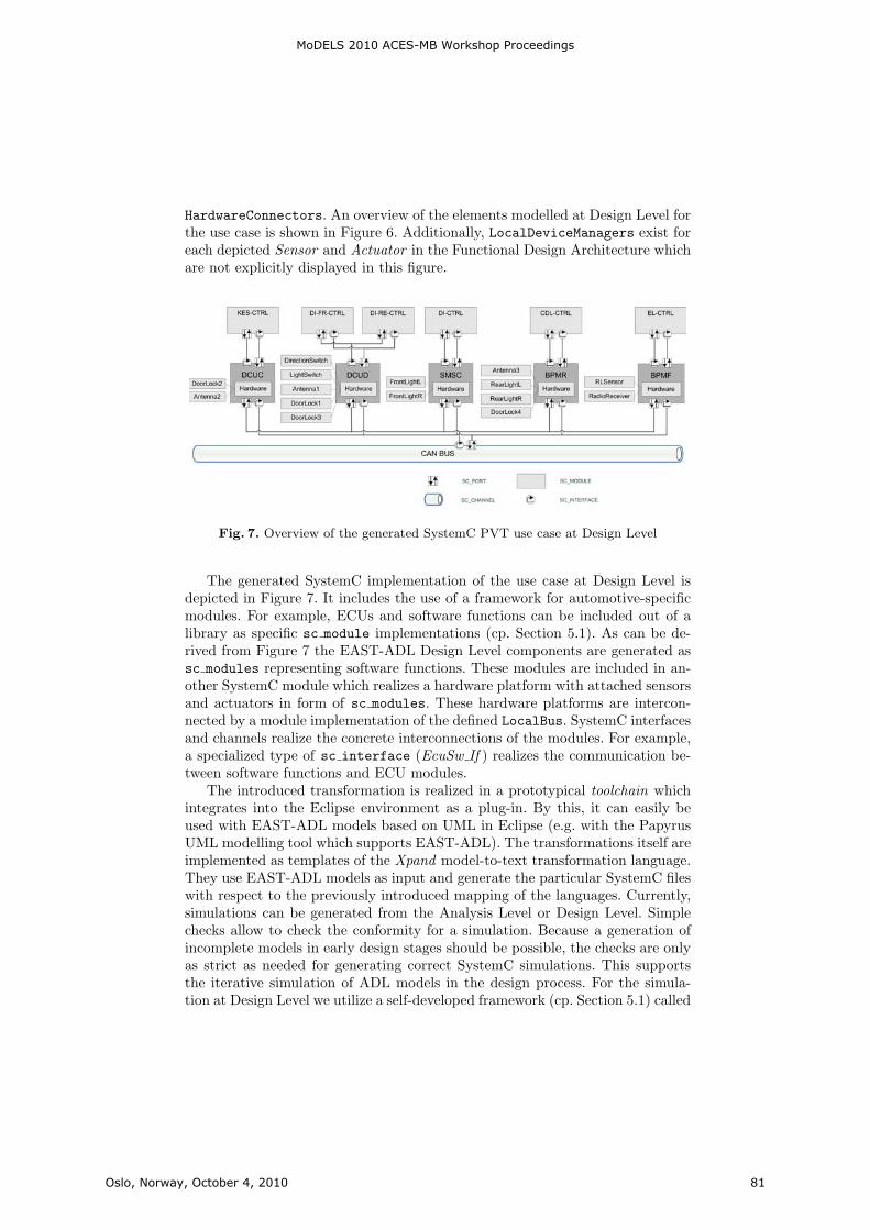
13
HardwareConnectors. An overview of the elements modelled at Design Level forthe use case is shown in Figure 6. Additionally, LocalDeviceManagers exist foreach depicted Sensor and Actuator in the Functional Design Architecture whichare not explicitly displayed in this figure.
Fig. 7. Overview of the generated SystemC PVT use case at Design Level
The generated SystemC implementation of the use case at Design Level isdepicted in Figure 7. It includes the use of a framework for automotive-specificmodules. For example, ECUs and software functions can be included out of alibrary as specific sc module implementations (cp. Section 5.1). As can be de-rived from Figure 7 the EAST-ADL Design Level components are generated assc modules representing software functions. These modules are included in an-other SystemC module which realizes a hardware platform with attached sensorsand actuators in form of sc modules. These hardware platforms are intercon-nected by a module implementation of the defined LocalBus. SystemC interfacesand channels realize the concrete interconnections of the modules. For example,a specialized type of sc interface (EcuSw If ) realizes the communication be-tween software functions and ECU modules.
The introduced transformation is realized in a prototypical toolchain whichintegrates into the Eclipse environment as a plug-in. By this, it can easily beused with EAST-ADL models based on UML in Eclipse (e.g. with the PapyrusUML modelling tool which supports EAST-ADL). The transformations itself areimplemented as templates of the Xpand model-to-text transformation language.They use EAST-ADL models as input and generate the particular SystemC fileswith respect to the previously introduced mapping of the languages. Currently,simulations can be generated from the Analysis Level or Design Level. Simplechecks allow to check the conformity for a simulation. Because a generation ofincomplete models in early design stages should be possible, the checks are onlyas strict as needed for generating correct SystemC simulations. This supportsthe iterative simulation of ADL models in the design process. For the simula-tion at Design Level we utilize a self-developed framework (cp. Section 5.1) called
MoDELS 2010 ACES-MB Workshop Proceedings
Oslo, Norway, October 4, 2010 81
14
DynaSim which allows the modelling of an automotive in-vehicle network in Sys-temC. The generated files refer to SystemC models in the DynaSim library (e.g.ECUs or software functions). By this, a simulation can be performed consideringthe automotive-specific system environment. Future work will be the automaticfeedback to the model as well as the integration and analysis of timing definitionsemantics.
7 Conclusion
Architecture Description Languages capture design information in architecturemodels. A simulation of these models in the development process allows an earlyvalidation. In this work we have briefly described the automotive-specific EAST-ADL and system modelling language SystemC. We showed that simulations fromEAST-ADL can be generated automatically by a transformation to SystemC.Therefore, the EAST-ADL layers of abstraction were compared and mapped tocorresponding layers of SystemC TLM. Also, transformation rules for the mod-elling artefacts of EAST-ADL with their concrete target elements in SystemCwere presented. The approach was evaluated with an automobile case study withrespect to the generation of simulations from EAST-ADL models on two differentlayers of abstraction. For this purpose a prototypical toolchain was built whichallows the automatic generation of SystemC simulations from EAST-ADL mod-els. By this, we showed that our approach allows the iterative simulation-basedvalidation of automobile functions at different layers of abstraction.
In future work we plan to refine this approach by focusing on the simulationand preservation of non-functional requirements (e.g. timing) and integratingexternally defined models. Additionally, more detailed automotive-specific Sys-temC models will be integrated in the simulation for a more precise analysis. Aspecial emphasis will be taken on the design and simulation-based validation ofadaptive embedded systems.
References
1. Medvidovic, N., Taylor, R.N.: A Classification and Comparison Framework forSoftware Architecture Description Languages. IEEE Transactions on SoftwareEngineering 26(1) (2000) 70–93
2. Cuenot, P., Frey, P., Johansson, R., Lonn, H., Reiser, M., Servat, D., Koligari, R.,Chen, D.: Developing Automotive Products Using the EASTADL2, an AUTOSARCompliant Architecture Description Language. In: Embedded Real-Time SoftwareConference, Toulouse, France. (2008)
3. Automotive Open Sytem Architecture (AUTOSAR): http://www.autosar.org4. IEEE: IEEE Standard 1666-2005 - System C Language Reference Manual. (2005)5. Cai, L., Gajski, D.: Transaction level modeling: an overview. In: Proceedings of
the 1st IEEE/ACM/IFIP international conference on Hardware/software Codesignand system synthesis (CODES+ISSS ’03). (2003) 19–24
6. SAE: Architecture Analysis and Design Language (AADL), document AS5506/1.http://www.sae.org/technical/standards/AS5506/1 (June 2006)
MoDELS 2010 ACES-MB Workshop Proceedings
Oslo, Norway, October 4, 2010 82

15
7. Chkouri, M.Y., Robert, A., Bozga, M., Sifakis, J.: Translating AADL into BIP -Application to the Verification of Real-Time Systems. In: Models in Software Engi-neering: Workshops and Symposia at MODELS 2008, Berlin, Heidelberg, Springer-Verlag (2009) 5–19
8. Varona-Gomez, R., Villar, E.: AADL Simulation and Performance Analysis inSystemC. In: Proceedings of the IEEE International Conference on Engineeringof Complex Computer Systems, Los Alamitos, CA, USA, IEEE Computer Society(2009) 323–328
9. Kugele, S., Tautschnig, M., Bauer, A., Schallhart, C., Merenda, S., Haberl, W.,Kuhnel, C., Muller, F., Wang, Z., Wild, D., Rittmann, S., Wechs, M.: COLA –The component language. Technical Report TUM-I0714, Institut fur Informatik,Technische Universitat Munchen (September 2007)
10. Wang, Z., Haberl, W., Kugele, S., Tautschnig, M.: Automatic generation of systemcmodels from component-based designs for early design validation and performanceanalysis. In: WOSP ’08: Proceedings of the 7th international workshop on Softwareand performance, New York, NY, USA, ACM (2008) 139–144
11. Krause, M., Bringmann, O., Hergenhan, A., Tabanoglu, G., Rosentiel, W.: Timingsimulation of interconnected AUTOSAR software-components. In: Proceedings ofthe conference on Design, Automation and Test in Europe (DATE ’07). (2007)474–479
12. Khlif, M., Shawky, M.: Enhancing Diagnosis Ability for Embedded ElectronicSystems Using Co-Modeling. In: Proceedings of the International Joint Conferenceson Computer, Information, and Systems Sciences, and Engineering. (2007) 3–12
13. Khlif, M., Shawky, M.: Co-modelling and Simulation with Multilevel of Granularityfor Real Time Electronic Systems Supervision. In: Proceedings of the 10th Inter-national Conference on Computer Modeling and Simulation (UKSIM 08). (2008)348–353
14. Krause, M., Bringmann, O., Rosenstiel, W.: A SystemC-based Software and Com-munication Refinement Framework for Distributed Embedded Systems. In: Pro-ceedings of the 13th Workshop on Synthesis And System Integration of MixedInformation Technologies. (2006)
15. Liang, L., Zhou, B., Zhou, X.G., Peng, C.L.: System Prototyping Based on Sys-temC Transaction-Level Modeling. In: Proceedings of the 1st International Multi-Symposiums on Computer and Computational Sciences (IMSCCS’06). (2006) 764–770
16. EAST-ADL2: Profile Specification 2.1 RC3.http://www.atesst.org/home/liblocal/docs/ATESST2 D4.1.1 EAST-ADL2-Specification 2010-06-02.pdf (June 2010)
17. Weilkiens, T.: Systems engineering with SysML/UML: modeling, analysis, design.Morgan Kaufmann (2007)
18. Open SystemC Initiative (OSCI): SystemC. http://www.systemc.org19. Donlin, A.: Transaction level modeling: flows and use models. In: Proceedings of
the 2nd IEEE/ACM/IFIP international conference on Hardware/software Code-sign and system synthesis(CODES+ISSS 04). (2004) 7580
20. TADL: Timing Augmented Description Language Version 2.http://timmo.org/pdf/D6 TIMMO TADL Version 2 v12.pdf (2009)
21. Hardung, B., Kolzow, T., Kruger, A.: Reuse of Software in Distributed EmbeddedAutomotive Systems. Proceedings of the 4th ACM international conference onEmbedded software (2004) 203 – 210
MoDELS 2010 ACES-MB Workshop Proceedings
Oslo, Norway, October 4, 2010 83

Model Maturity Levels for Embedded SystemsDevelopment, Or: Working with Warnings
Martin Große-Rhode
Fraunhofer Institute for Software and Systems Engineering, Berlin, [email protected]
Abstract. The more modelling substitutes programming the more mod-elling tools should become development environments. Beyond enforcingthe syntactic correctness of models tools should support a methodologi-cally guided development in which milestones are indicated and warningsare generated to inform the user about issues that are to be solved toreach these milestones. In this paper we present an approach from theembedded systems domain that is materialized by the implementationof a prototypical model development environment. It indicates modelmaturity levels that correspond to an underlying development methodand shows in the model maturity view which elements or parts of themodel do not yet reach a level and why they do not reach it.
1 Introduction
Program development environments have led to a substantial increase of pro-ductivity in the construction of software. Completion suggestions based on thegrammar of the programming language and the code produced so far, navigationin large amounts of code according to different kinds of relations, like placeof declaration or place of usage, and, of course, the indication of errors andsuggestions how to correct them reduce the time needed to produce compilablecode drastically. Beyond the necessary conditions to produce code that can becompiled warnings are generated by the environment that indicate code qualityaccording to different criteria. These warnings can be used to produce bettercode, or be ignored if they are considered not relevant.
Model development deserves the same kind of comprehensive support. Whethermodelling is employed to replace programming as in pure generative approachesor to support programming by stating requirements, designs, and algorithmsconcisely, the development of models is an engineering task and bears its owncomplexity. Therefore it is not enough to be able to build a model. Constructionsupport, navigation, indication of errors and methodological support are needed,too.
The modelling language and tool used as example in this paper have beendesigned for the automotive domain, in particular the development of AUTOSARsystems (see [AUT]). The AUTOSAR extension language aXLang (see [aXBench])is a component description language that is used in the early process stages to
MoDELS 2010 ACES-MB Workshop Proceedings
Oslo, Norway, October 4, 2010 85
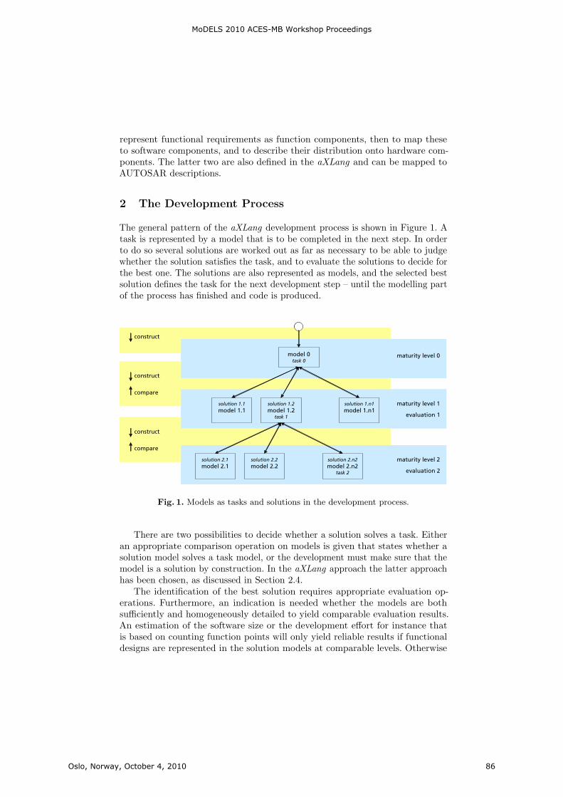
represent functional requirements as function components, then to map theseto software components, and to describe their distribution onto hardware com-ponents. The latter two are also defined in the aXLang and can be mapped toAUTOSAR descriptions.
2 The Development Process
The general pattern of the aXLang development process is shown in Figure 1. Atask is represented by a model that is to be completed in the next step. In orderto do so several solutions are worked out as far as necessary to be able to judgewhether the solution satisfies the task, and to evaluate the solutions to decide forthe best one. The solutions are also represented as models, and the selected bestsolution defines the task for the next development step – until the modelling partof the process has finished and code is produced.
Fig. 1. Models as tasks and solutions in the development process.
There are two possibilities to decide whether a solution solves a task. Eitheran appropriate comparison operation on models is given that states whether asolution model solves a task model, or the development must make sure that themodel is a solution by construction. In the aXLang approach the latter approachhas been chosen, as discussed in Section 2.4.
The identification of the best solution requires appropriate evaluation op-erations. Furthermore, an indication is needed whether the models are bothsufficiently and homogeneously detailed to yield comparable evaluation results.An estimation of the software size or the development effort for instance thatis based on counting function points will only yield reliable results if functionaldesigns are represented in the solution models at comparable levels. Otherwise
MoDELS 2010 ACES-MB Workshop Proceedings
Oslo, Norway, October 4, 2010 86

the more detailed models always yield the worse estimations, independently ofthe adequacy of the design they represent. The indication of the appropriatenessfor an evaluation that demarcates a specific development stage is called a modelmaturity level. In general, development stages should always be defined by theevaluations that have to be passed and the validation operations that are possibleat a stage.
In the aXLang process up to now the following model maturity levels aredefined:
Level 1 Function Interface ModelLevel 2 Function Simulation ModelLevel 3 Deployment ModelLevel 4 AUTOSAR Model
The first two are described in more detail in the following. They can be appliedto any component description language. The third level is specific to languagesthat incorporate an application level and a resources layer. The fourth level isspecific to AUTOSAR.
2.1 Function Interface Model
The function interface model is the first model constructed in an aXLang process.It represents one application function of an embedded system and specifies whichinformation this function exchanges with the environment or other functionsin the system. Its main usage is virtual integration, i. e. the check whether theapplication functions that make up the system according to their interfaces fitto each other. The model is derived from a use case analysis of the function. Afunction interface model has the following elements.
– one component, the one that represents the function;– the input and output ports of the component;– the logical signals and the operation calls the function shall accept or is
allowed to deliver to other ones via its ports;– the services of the component that represent the expected i/o-behaviours of
the function;– and its internal storages that are used to specify stateful functions.
As indicated in Figure 2 the elements of the model correspond to questions thatshould be posed to gather the functional requirements systematically. The modelstructure thus serves as a schema for the requirements elicitation.
At the function interface level the services are the use cases of the function.They are described informally by natural language texts, but constrained by aschema implemented in the language that guarantees that only the behaviourvisible at the interface is described, and that only declared elements (ports, signals,operation calls, storages) are used for the description. The schema contains slotsfor the precondition, the interaction, and the postcondition of the service. Withinthe textual description references to ports, signals, operation calls, and storages
MoDELS 2010 ACES-MB Workshop Proceedings
Oslo, Norway, October 4, 2010 87

Fig. 2. Function interface model as requirements elicitation schema.
are marked such that their declaration in the function interface model can bechecked and renamings can be carried through as consistent refactorings.
As running example we use the function Condition Based Service (Cbs). Itmonitors the state of a vehicle and computes a summary of the overall stateof the vehicle (green, yellow, red) and a car maintenance service date, i. e. asuggestion when to go next to the service. The function has been a case study ina project with the BMW Group (see [VEIA]). A graphical representation of itsinterface model is shown in Figure 3, the aXLang description in Table 1.
The behaviour description of the service compute cbs data is given as follows.
service compute_cbs_data {...behavior {precondition {$The ’ignition’ is on.
$}
interaction {$1. For each adaptive volume Cbs reads the ’relative_wear’
from the corresponding sensor port.2. Cbs computes the ’service_date’ and the ’summary_estimation’.
$}}...
}
References are indicated by ’ ’, as in ’service date’ and ’summary estimation’.Deriving function interfaces in this liberal but constrained way turned out to
be very constructive in the industry projects in which a predecessor of the languagehas been used (see [Gro08]). The basic idea is that functions are understood bestin terms of their behaviour and that the structure of the function can be elicitedmost concisely if it is based on a use case analysis. On the other hand, the method
MoDELS 2010 ACES-MB Workshop Proceedings
Oslo, Norway, October 4, 2010 88
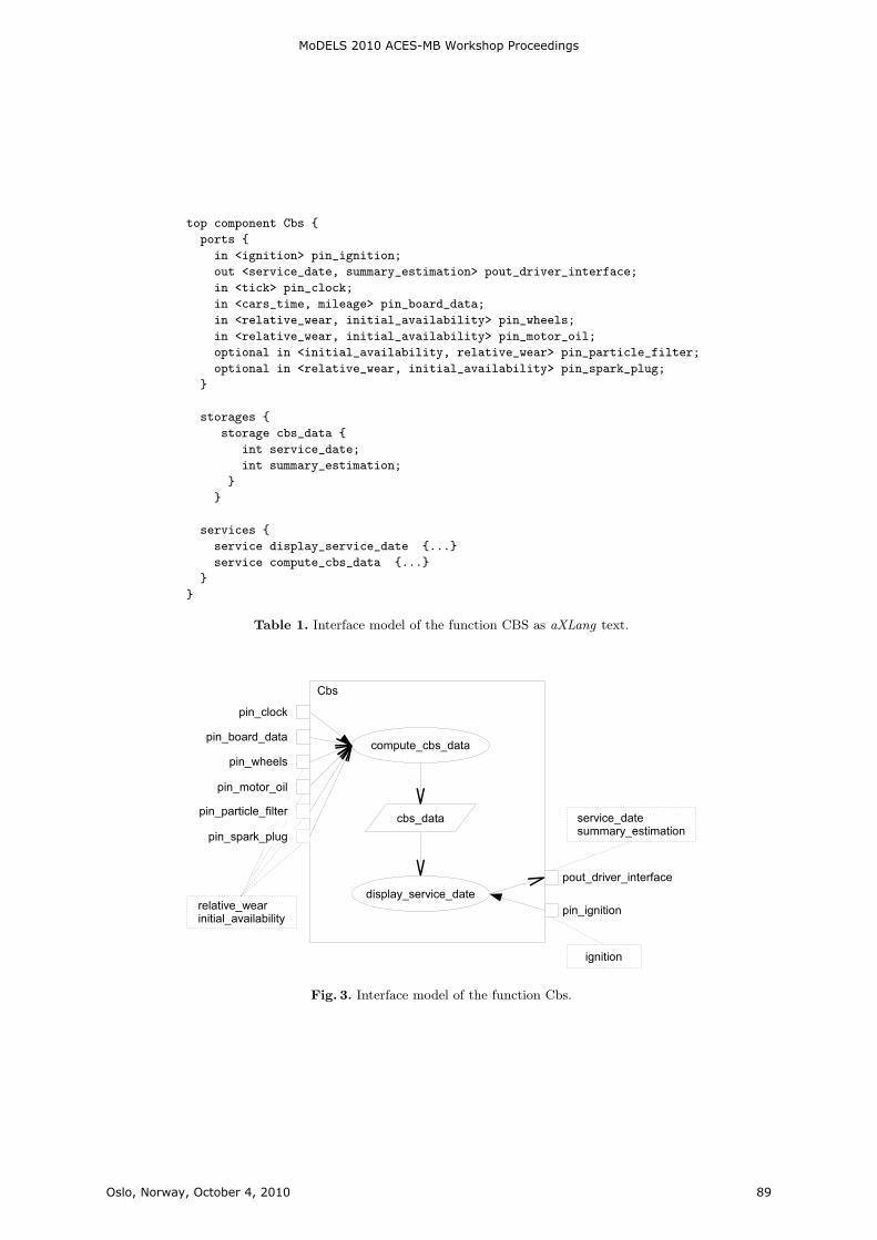
top component Cbs {
ports {
in <ignition> pin_ignition;
out <service_date, summary_estimation> pout_driver_interface;
in <tick> pin_clock;
in <cars_time, mileage> pin_board_data;
in <relative_wear, initial_availability> pin_wheels;
in <relative_wear, initial_availability> pin_motor_oil;
optional in <initial_availability, relative_wear> pin_particle_filter;
optional in <relative_wear, initial_availability> pin_spark_plug;
}
storages {
storage cbs_data {
int service_date;
int summary_estimation;
}
}
services {
service display_service_date {...}
service compute_cbs_data {...}
}
}
Table 1. Interface model of the function CBS as aXLang text.
Fig. 3. Interface model of the function Cbs.
MoDELS 2010 ACES-MB Workshop Proceedings
Oslo, Norway, October 4, 2010 89
must make sure that behaviour descriptions are constrained to interactions withthe environment; internal behavior must not be specified here. This is achieved inthe aXLang by checking that each phrase in the behaviour description containsreferences to the elements declared in the interface model, i. e. each phrase mustrefer to an externally visible interaction. In the Cbs behaviour description theignition signal is indicated as well as the input signals relative wear and theoutput signals service date and summary estimation.
The usage of storages and the description of the access of a function to itsstorage in a use case might seem to contradict this principle. However, storages areconsidered as interface elements in the sense that they are only used as abstractmeans to describe that the function has a state. So the reader of a functioninterface model should be informed about the statefulness of the function, and inthe refinement the storages must be refined and finally be implemented, too. Inthe Cbs example the storage of the Cbs data is used to decouple the continuous(periodic) computation of the Cbs data from its occasional display, triggered bythe driver turning on the ignition.
The properties that are checked for the model maturity level function inter-face model are systematically derived from this methodological approach. Eachelement must be justified by its contribution to a use case. Since the model is arequirements model for the further development this strict rule itself is justified:Later on each element must be implemented, which results in development costs.Therefore no superfluous elements are allowed in the model.
The first set of properties that is checked is whether there is at least oneservice in the function, and whether each service has a use case (behaviour)description.
The second set of properties concerns the interconnection of the service withthe structural elements of the function. Each service must have at least onetrigger, which is given by a port and a signal or an operation call declared forthat port. Moreover, the service must yield a result, i. e. there must be a portonto which the service writes an output or, in the case of a stateful function, theremust be a storage to which the service delivers a result. Since these propertiescannot be deduced automatically from the natural language descriptions thelanguage contains service specification slots where read and write accesses toports and storages are declared. The corresponding part of the specification ofthe Cbs service compute cbs data is:
service compute_cbs_data {trigger pin_clock.tick;read pin_ignition.ignition;read pin_wheels.relative_wear;read pin_motor_oil.relative_wear;read pin_particle_filter.relative_wear;read pin_spark_plug.relative_wear;write service_date;write summary_estimation;
MoDELS 2010 ACES-MB Workshop Proceedings
Oslo, Norway, October 4, 2010 90
behavior {...}...
}
Checking the properties thus is a simple task; having these declarations in themodel, however, is an important methodological contribution and within largerdevelopments their indication in the maturity level view is indeed helpful.
Now, as mentioned above, it is checked whether all structural elements arejustified by a use case. First for each port it is checked whether signal or operationcalls are declared for this port at all; otherwise it is superfluous. Then it is checkedwhether the incoming signals and operation calls at the port are read by someservice and whether the declared outgoing signals and operation calls are providedby some service. The analogous property is checked for the storages: each onemust be both written and read by one or more services.
2.2 Dealing with Variants
Since the aXLang has been designed for the automotive domain it must providemeans to deal with variants. At the architectural level, including the functioninterface models, variability can be expressed by alternatives, encapsulated inmutually exclusive elements (xor), optional elements, and parameterised elements(see [MR09]). In the case of a function interface model ports, signals, operationcalls, and storages can be optional; services can be xor, i. e. product specificbehaviours of a service can be specified.
Since the product specific behaviour and structure of a system in generalcannot be localized to one place in the architecture but is spread over severalcomponents, feature models are employed to encapsulate the variance. An aXLangmodel altogether thus consists of several specific models. One is the applicationmodel, a model of the component architecture of the application view of thesystem. The function interface model is an application model at the first levelof maturity; it represents an application function as one component. A secondone is the feature model that characterizes the commonalities, differences, anddependencies of the different variants of the system in terms of abstract systemfeatures. The feature model is a tree of features indicating the mandatory, optional,and alternative features of the products of the system family. A mapping ofthe features to the application model defines which of the variant architectureelements are present in a system variant when a given configuration of features isselected. (For an introduction to feature oriented software product line engineeringsee [KLLK02].)
In the model of the Cbs function we have optional ports for the particle filterand spark plug sensor inputs because these are not present in all vehicles. Theyare indicated by the keyword optional (see Table 1). Whether one of the optionalports is present depends on whether the vehicle has a diesel or a gasoline engine.This is expressed in the feature model and the mapping of the feature model tothe application model (f2a mapping):
MoDELS 2010 ACES-MB Workshop Proceedings
Oslo, Norway, October 4, 2010 91
featuremodel CbsFeatures {features {xor engine {diesel;gasoline;
}}
}...f2a_mapping CbsApplicationBinding CbsFeatures -> CbsApplication {\\ feature to port linksf2p_links {engine.diesel -> pin_particle_filter;engine.gasoline -> pin_spark_plug;
}}
The feature mapping is estimated according to the same principle as above:each element must be justified. In this case this means first that each optional oralternative feature of the feature model must be mapped to an element of thefunction interface model and that each variant element of the function interfacemodel must be bound by a feature. Furthermore the semantics of the features andthe variant element must be respected: No mandatory feature must be mappedto a variant architecture element and no invariant architecture element must bebound by a variant feature.
2.3 Evaluation of Function Interface Models
As mentioned above a development stage should be defined by the evaluationsthat have to be performed and by the validation operations it allows.
The validation operation that becomes possible (and meaningful) with functioninterface models is virtual integration, i. e. the check whether the interfaces ofthe application functions of the systems fit to each other. For that purpose asystem model is built by connecting the considered function interface models.More precisely: the ports of the function interface models are connected to specifywhich functions are senders and receivers of which signals and operation callsrespectively. Communication with the environment is modelled by encapsulatingthe function interface models in a common super component (the system) anddelegating the corresponding ports to the ports of the super component (seeFigure 4). Composition and decomposition of components are discussed in moredetail in section 2.4.
The necessary condition of the virtual integration is that each required signaland operation is provided, either within the system or by the environment. Inputsignals are required by a function, otherwise it would not be able to produceits output. Thus the connections in the system must be checked as to whethereach signal is delivered somewhere and transported to the requesting function.
MoDELS 2010 ACES-MB Workshop Proceedings
Oslo, Norway, October 4, 2010 92

Fig. 4. Virtual integration of function interface models.
Operation calls are required by a function if they are sent from an output port.There must be a function that receives the function call at an input port, andoperates it.
A sanity check can and should be performed here, too. If a function providesa signal at one of its output ports, there should be someone in the system orthe environment who needs the signal; i. e. there must be a connection to theinput port of a function where the signal is consumed, or an explicit delegationto the environment. Otherwise the specification would require the generation of auseless signal by the originating function – which produces development overhead.Since the implementor of the function typically does not receive the whole systemmodel but only the model of the function she cannot check whether the requiredfunctionality is indeed needed. Analogously, operation calls at input ports of afunction are checked: is there someone in the system or the environment whoneeds (calls) the operation? If no, remove it from the specification.
The evaluations of a function interface model implemented in the aXBench,the modelling environment for the aXLang, are estimations on the size of thesoftware and the effort of its development. Both are based on a metric for systemfamily models (see [KFS06]) that is an extension of the function point metricsto specifications including variance. The first estimation, the software size, isimportant for the cost estimation of the product (the necessary size of memories),the second one is important for the cost estimation of the process.
The aXBench furthermore provides an interface for the integration of otherevaluation operations. Metrics that count elements as the one mentioned above,for instance, would get the elements of the model via the interface and delivertheir results as a view to the aXBench.
2.4 Function Simulation Model
The behaviour of a function has been described in the function interface modelin natural language only. The second milestone in its development is reachedwhen an executable model is delivered.
MoDELS 2010 ACES-MB Workshop Proceedings
Oslo, Norway, October 4, 2010 93

In general an application function of an automotive system is too large asto be immediately modelled in such detail that the model can be executed.Therefore the model has to be decomposed into components representing parts ofthe function that are small enough to be provided with an executable description.
Decomposition is supported in the aXLang as in most other componentor architecture description languages by component hierarchies. To allow themultiple use of subcomponents of the same type, the hierarchy is not directlyrepresented in the language. Instead, components and subcomponents are differententities in the metamodel; a component (strongly) aggregates subcomponents andeach subcomponent has a reference to a component that is its type. This encodingof hierarchies via instance-type relations is common in component or architecturedescription languages, as for instance in the UML composite structure diagrams,EAST-ADL, AADL, and AUTOSAR.
Executable behaviour is described in the aXLang by programming languagecode. Beyond the standard assignments and control structures it contains expres-sions for the access to the ports of the function. A write statement, used for theemission of signals and operation calls respectively, is of the form write(port.signal,value) or write(port.operation, par 1 value, ..., par n value). An expression forreading a signal at a port has the form read(port.signal). Operation parameterscan be read in the function that received the call with read(port.operation, par j).
Checking the function simulation model maturity level first means to checkwhether each service of an atomic function has an executable behaviour descrip-tion. Only atomic functions are checked because the decomposition overwritesthe higher level description. The behaviour of the composed function is com-pletely described by the composition of the behaviour of the subfunctions. Thehigher level function does not add behaviour to its parts, but just organizes theirinterconnection by connecting their interfaces.
The replacement of the function interface model by the function simulationmodel via decomposition implies the further checks that are performed to reachthe function simulation model maturity level.
The first part is the structural decomposition. According to the definition ofthe language subcomponents can only be introduced and interconnected withinthe component that is decomposed. Thus the structural coincidence of the functioninterface model with the top level of the function simulation model is guaranteedby construction (see Figure 5).
What has to be checked, however, is whether the subcomponents are connectedwith each other correctly and whether they are connected with the higher levelcomponent correctly. Both amounts to checking the data flow in the composition,as in the virtual integration discussed above. Each required signal or operationcall at the port of some subcomponent must be provided either by anothersubcomponent via a connection or by the super component via a delegation. Tobe economic, furthermore, each provided signal or operation must be requestedby another subcomponent or the super component.
The second part of the check concerns the behavioural decomposition, or,to be more precise, the structural aspect of the behavioural decomposition. A
MoDELS 2010 ACES-MB Workshop Proceedings
Oslo, Norway, October 4, 2010 94
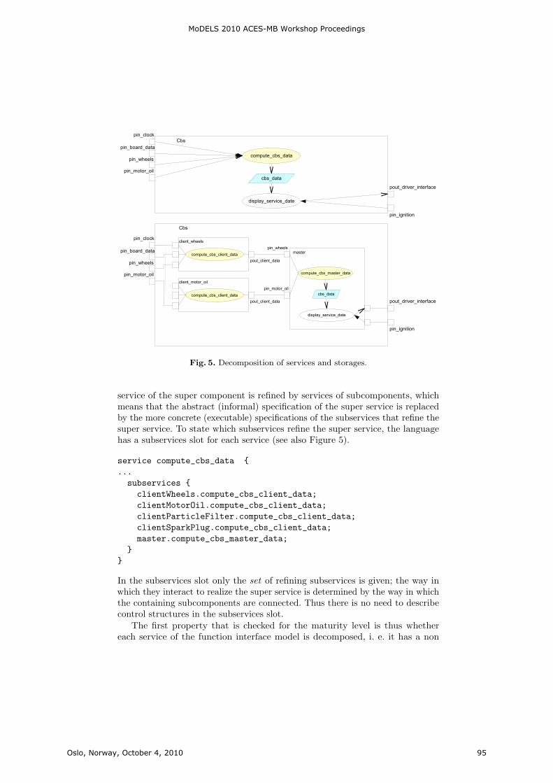
Fig. 5. Decomposition of services and storages.
service of the super component is refined by services of subcomponents, whichmeans that the abstract (informal) specification of the super service is replacedby the more concrete (executable) specifications of the subservices that refine thesuper service. To state which subservices refine the super service, the languagehas a subservices slot for each service (see also Figure 5).
service compute_cbs_data {...subservices {clientWheels.compute_cbs_client_data;clientMotorOil.compute_cbs_client_data;clientParticleFilter.compute_cbs_client_data;clientSparkPlug.compute_cbs_client_data;master.compute_cbs_master_data;
}}
In the subservices slot only the set of refining subservices is given; the way inwhich they interact to realize the super service is determined by the way in whichthe containing subcomponents are connected. Thus there is no need to describecontrol structures in the subservices slot.
The first property that is checked for the maturity level is thus whethereach service of the function interface model is decomposed, i. e. it has a non
MoDELS 2010 ACES-MB Workshop Proceedings
Oslo, Norway, October 4, 2010 95
empty subservices slot. Next the declaration of the interconnection of the superservice within the super component is checked: Are its triggers and read andwrite accesses correctly refined by the decomposition?
The decomposition must show the same effects at the function interface as thesuper service, i. e. it must neither introduce new inputs or outputs nor must itignore inputs or outputs of the super service. If a decomposition of a service wouldrequire more input than the super service the integration of the implementedfunctions would fail. If it provides more output more implementation work thannecessary would have to be done.
In order to check this property the data flow of the subcomponents accordingto the declaration of their services (read and write accesses inside the subcompo-nents) and their connections (data flow in between the subcomponents) has tobe computed. With this information the read and write accesses of the composedsubservices to the ports of the function interface can be compared with the readand write accesses of the super service declared in the function interface model.
Analogous to the decomposition of the services of the super component intoservices of the subcomponents the storages must be decomposed. For that purposethe aXLang provides a substorages slot in the specification of a storage:
top component Cbs {...storages {storage cbs_data {
int service_date;int summary_estimation;substorages {master.cbs_data {service_date -> master.cbs_data.service_date;summary_estimation -> master.cbs_data.summary_estimation;
}}
}}
}
In the example the storage is not distributed to subcomponents but resides inone single component, the master.
Using the substorages declaration also the correct decomposition of the readand write accesses of higher level services to their storages can be checked. Ifthe super service has read or write access to a storage then at least one of itssubservices must have an access of the same type to at least one of the substorages.Vice versa the subservices must not introduce more accesses than declared bythe superservice.
Obviously the analysis of the decomposition is not complete. It covers onlythe structural declarations at the two levels. Whether the behaviour respectsthe declarations is another issue, which requires program or behaviour modelanalysis techniques that are not incorporated into the aXBench yet.
MoDELS 2010 ACES-MB Workshop Proceedings
Oslo, Norway, October 4, 2010 96
2.5 Refinement and Iteration
The check of the consistency of the function interface model and the functionsimulation model is based on the correctness of the decomposition. The basic ideathereby is to use hierarchical decomposition as refinement. Since the interface ofthe abstract model is fixed – additions are only made in the internal structure – wethus have substitutability by construction. In whatever way the function interfacemodel is refined it fits structurally into the overall system. The decompositioninformation in the function interface model, i. e. the subservices and substoragesslots, allows requirements tracing. They indicate the implementation (compositionof lower level services) of a functional requirement (description of a higher levelservice) as well as the implementation of the required state properties.
In a development process, however, requirements typically are not entirelystable. One reason is that the more detailed design of a solution often reveals that,for instance, more input is needed by a function to compute its outputs, or thata restriction to less output would make the overall design more adequate. Havingboth the abstract super component (the requirements) and the subcomponents(the solution design) as hierarchy levels in one model supports the proliferationof requirements changes immediately. The maturity level check indicates whethernew input signals for instance have been introduced at the sublevel but not yetdelegated to the super level. Thus the user receives a warning that the interface ofthe super component has to be updated. Changing this interface must of coursebe reflected by a revision of the virtual integration, which can and should notbe automated. However, the maturity level check provides the methodologicalsupport for the users’ activities that yield concisely documented requirementschange requests. The management of the changed requirements is best supportedby organizational means in the process.
2.6 Simulating Models with Variants
The possible evaluations of the function simulation model are the same as theones for the function interface model: counting elements to measure the predictedsoftware size and development effort. The difference is that the basis for theestimation is now more detailed and thus the prediction more precise.
The major advantage of the function simulation model is that simulationbecomes possible to validate and to debug the model. The aXBench has asimulation machine that uses the aXLang programming language description ofthe services’ behaviours and the interconnection as expressed in the structure, i.e. the connection of the subcomponents.
A challenge in the automotive domain, as mentioned above, is dealing withvariants. One possibility is to derive product specific models from the familymodel and then to simulate each of these. The aXBench has an operation thatperforms this derivation. Given an application model, a feature model, a feature-to-application mapping, and a feature configuration (i. e. a consistent subset ofthe feature model) it returns a new application model where all variant elementsthat are not bound to features in the configuration are removed. The removal of
MoDELS 2010 ACES-MB Workshop Proceedings
Oslo, Norway, October 4, 2010 97

course respects all dependencies such that the result of the operation is a correctmodel again.
However, this procedure is tedious and neglects the advantages of product lineengineering, namely to use only one model for all variants. A better solution is toprovide a simulation that simulates all variants simultaneously, i. e. a simulationof the family model. The essential idea thereby is that each simulation runcollects all configuration decisions that must be drawn in order to realize this run.Thus whenever a run encounters an xor component with its delegations to thealternatives it splits into all alternatives and memorizes in each branch that thisalternative has been chosen. The result is then a tree of events where in each stepthe selected variant elements are indicated. This result can be used to identifybehavioural invariants (commonalities) as well as to validate the variant specificbehaviour (differences). The details of this system family model simulation areout of the scope of this paper, however.
3 Summary and Conclusion
Modelling is a part of the development process. In order to be useful it mustbe guided by a method and supported by a tool that does not only allow theconstruction of models but gives feedback on the state and the quality of themodels.
The model maturity levels discussed in this paper are an effort to supplythis kind of support, without constraining the development activity unduly.A distinction is made between syntactically correct models and models that –beyond that – represent milestones of the process. Error messages and correctionsuggestions are given in the case of violations of syntactic rules. Warnings areused to indicate what is missing in order to reach the maturity levels definedin the process. These warnings are grouped according to the checks that arepreformed for the different levels, as discussed above. Within these groups theelements that are the causes for not passing a test are given and linked with themodel editor such that corrections or amendments can be made immediately.Analogous to program development environments, the idea is to rise the efficiencyof the modelling process by this support, and to achieve models of a better –since checked – quality.
Beyond the two maturity levels discussed in this paper two further ones areimplemented in the aXBench. The first one, the deployment model maturity level,addresses models that contain a further specific model, the resource model. Thisone represents the computation and communication resources of the system, i. e.the nodes (electronic control units) and the buses and other communication meansof the system. Similar to the feature-to-application mapping the aXLang supportsthe specification of application-to-resource mappings that define how the functionsare allocated to the nodes and how the application level communication is realizedby the communication infrastructure of the underlying system. The correspondingmaturity level is checked according to the same principles as discussed above. Are
MoDELS 2010 ACES-MB Workshop Proceedings
Oslo, Norway, October 4, 2010 98
all relevant model elements present; are all elements justified; are the semanticsrespected?
Having the resource level included in the model further evaluations are possible.A real time behaviour analysis for example can be made, provided information isgiven on the real time behaviour of the resources. A prototypical implementationof a schedule analysis algorithm has been used in the aXBench to illustrate theintegration of an evaluation operation into the aXBench development process.The long term goal, however, is to use the aXBench interface to connect other,more professional evaluation tools.
The next maturity level indicates the AUTOSAR interface, i. e. the step in theprocess where the requirements and function design models of the aXLang canbe handed over to the system generation process of the AUTOSAR methodology.The check of this maturity level is done constructively. The AUTOSAR exportoperation tries to translate an aXLang model to an AUTOSAR representation,and thereby collects all obstacles, i. e. all elements that cannot be translated toAUTOSAR. This yields the warnings of the AUTOSAR maturity level that arepresented to the user in the maturity level view.
As discussed above the definition and implementation of a maturity level mightnot be technically challenging. Rather, a detailed analysis of the methodologicalrole of the model’s elements is required. The effect of the maturity level checksand the presentation of the results as a view in the tool, however, is considerable,as the programming development environments have shown.
References
[AUT] AUTOSAR development cooperation. AUTOSAR – Automotive OpenSystem Architecture. www.autosar.org
[aXBench] aXBench-Homepage. The Autosar Extensible Workbench.axbench.isst.fraunhofer.de
[Gro08] Martin Große-Rhode. Methods for the Development of Architecture Modelsin the VEIA Reference Process. ISST-Bericht 85/08, Fraunhofer-Institutfur Software- und Systemtechnik, May 2008.
[KFS06] Sebastian Kiebusch, Bogdan Franczyk, and Andreas Speck. An unadjustedsize measurement of embedded software system families and its validation.Software Process: Improvement and Practice, 11(4):435–446, 2006.
[KLLK02] Kyo Chul Kang, K. Lee, J. Lee, and S. Kim. Feature oriented productline software engineering: Principles and guidelines. In Domain OrientedSystems Development – Practices and Perspectives. Gordon Breach SciencePublishers, 2002.
[MR09] Stefan Mann and Georg Rock. Dealing with variability in architecture-descriptions to support automotive product lines. In David Benavides,Andreas Metzger, and Ulrich Eisenecker, editors, Proc. 3rd Int. Workshopon Variability Modeling of Software-intensive Systems (VAMOS 2009),ICB-Research Report No. 29, pages 111–120.
[VEIA] VEIA-Homepage. Verteilte Entwicklung und Integration von Automotive-Produktlinien. veia.isst.fraunhofer.de
MoDELS 2010 ACES-MB Workshop Proceedings
Oslo, Norway, October 4, 2010 99

Towards a Systematic Approach for SoftwareSynthesis
Hamid Bagheri and Kevin Sullivan
University of Virginia,151 Engineer’s Way,
Charlottesville, VA 22903 USA{hb2j, sullivan}@virginia.edu
Abstract. Development of software-intensive systems nowadays rely ex-tremely on middleware platforms as a major building block especially tohandle the distribution issues. This dependency has become even morecrucial in the distributed embedded systems environment. As such, thearchitectural choices of such systems are being driven by middlewareplatforms. However, diversity and high frequency of evolution in middle-ware platforms lead to architectural models becoming obsolete relativelyrapidly, which is in distinct contrast to the resistance nature of softwarearchitecture to frequent change. We believe that the key to this is to ab-stract away from architectural platforms and their induced architecturalstyles to more abstract representation of applications. In recent workwe have shown that architecture-independent application models, devel-oped using modern model-based development (MBD) techniques, can bemapped to application architectures in a variety of architectural styles.Although the work provided an important proof of concept, the styles,or architectural spaces, to which application models were being mappedwere simple, idealized styles. Di Nitto and Rosenblum recognized thatmiddleware and similar platforms induce defacto architectural styles. Inthis paper, we discuss some of the related issues we are addressing in ourresearch towards a systematic approach for software synthesis.
1 Introduction
Software-intensive systems are continuously growing in size and complexity. Inrecent years, they have ever more migrated from the traditional, localized settingto highly distributed, and embedded environments. While software engineeringresearchers and practitioners have recognized software architecture as a promis-ing means of managing the complexity of software systems in general [17, 15],other studies have shown its significant role in developing distributed embeddedsystems [16, 11].
Distributed embedded systems, furthermore, rely extremely on middlewareas a major building block to handle the distribution issues [8]. However, becauseof the pervasiveness of middleware platforms, the architectural choices are beingdriven by such platforms and since they are both changing rapidly and are very
MoDELS 2010 ACES-MB Workshop Proceedings
Oslo, Norway, October 4, 2010 101
diverse, the architecture of most of software-intensive systems and distributedembedded systems, in particular, are accidental nowadays [5]. This is in distinctcontrast to the way that software architecture is designated to be, i.e. softwarearchitecture typically comprises the early decisions made about a system, andis consequently very difficult to change [17]. As such, there is a pressing need tounderstand how to make architectural changes much more readily.
We believe that the key to this is to abstract away from architectural stylesand architectural platforms to more abstract representation of applications. Inrecent work [2] we demonstrated the feasibility of separating and combiningformal representations of application properties and architectural styles, respec-tively. In doing so, we defined style-specific architectural mappings that relatestyle-independent application models to architectural models in given styles.
We have continued studying the notion of architectural mappings and theways in which they can be defined and exploited in system development. In thispaper we discuss some of the issues we are addressing in our work.
2 Previous Work
Our earlier work [2] suggests that the concept of application type, parallel to thenotion of architectural style, is important, and that it is possible to separate, andcombine formal representations of, application contents and architectural styles,respectively. To that end, we formulate the mapping problem as one of findingsatisfying solutions to a specification that combines an application model of agiven application type, with an architectural style specification, and with rulesfor mapping application models of the given type to architectural models in thegiven style. We have implemented such mappings using Alloy as a language andsatisfaction engine [9].
In view of the increasing platform diversity and complexity of software-intensive systems, model-based development (MBD) approach has become aviable means to address system-integration issues in the early phases of develop-ment. In recent work [3] we showed that software architectural styles can serve asanalogs to choices of platforms in model-based development, and that the con-cept of application type leads naturally to an abstract, user-friendly approach toapplication modeling. That is, the proposed separation of concerns supports amodel-based development and tools approach to architectural-style-independentapplication modeling, and architecture synthesis with style as a separate designvariable. More precisely, by providing a prototype tool, Monarch [1], we illus-trated how an approach giving as inputs the formal specifications of applicationdescriptions and architectural styles can be implemented in a computationallyeffective manner by being placed within the formal framework of MBD.
These work provided a proof of concept of the feasibility of the proposedformal architectural mappings in an automated way. However, it suffers fromsome shortcomings especially with respect to the pervasiveness of middleware insystem development. In the next section, we discuss some of the ongoing issueswe are addressing in our work.
MoDELS 2010 ACES-MB Workshop Proceedings
Oslo, Norway, October 4, 2010 102
3 Proposed Work
3.1 Middleware-induced architectural styles
Middleware infrastructures are emerging to be used extensively as a majorbuilding block in facilitating system development especially in the large-scaledistributed systems. Notwithstanding the several categories of middleware plat-forms, there are numerous middleware infrastructures from which to choose suchas TAO [13], Aura [16], PolyORB [18] and even Enterprise JavaBeans (EJB) [6].
An approach that may be commonly used and could be ineffective and coun-terproductive in practice is that a middleware is chosen first with respect toits provided services and in turn leads to an unnecessary impact over the sys-tem’s architecture. In contrast, deferring middleware decisions has several ad-vantages such as separation of concerns and promoting level of abstraction inthe early phase of software design [12, 17]. Furthermore, a middleware decisionis not independent of the system’s architecture. As such, decisions made duringthe development of the system’s architecture may limit the decision space of themiddleware that will be used to implement the system.
Problems can arise when the architectural styles chosen for the applicationconflict with the assumptions of the chosen middleware. Blair et al. [4] arguethat the architectural models can be used in systematic synthesis of middle-ware configurations. Particularly, it would be helpful to consider structural andbehavioral constraints implied by middleware infrastructures as architecturalstyles [12]. Formal definition of these styles will allow architects to exploit thesestyles in a way that avoids unintentional mismatch between the required ap-plication’s properties and the constraints imposed by the middleware-inducedarchitectural styles.
Although a number of approaches explored to separate and relate middlewareinfrastructures and architectural styles induced by them in various domains (e.g.embedded systems [11], web-based systems [7]) insufficient progress has beenmade on mapping architecture-independent application models into the mod-ern and practical, middleware-induced architectural styles and in turn, into therealized architecture implementations. We envisage an approach that is basedon model-based development to mapping architecture-independent applicationmodels, considered as platform-independent models, to the realized architectureimplementations in conformance with the architectural styles that are induced bymiddleware platforms and other complex and practical application frameworks.This approach can be used to automate the derivation of the architectural models(Platform-specific models) from the application models (Platform-independentmodel) that refines application types.
3.2 Code Generation
The architectural styles so derived promise benefits for both development andmaintenance. However, formal specifications often lack bindings to implementation-level constructs. Thereby, it is particularly difficult to verify the fidelity of the
MoDELS 2010 ACES-MB Workshop Proceedings
Oslo, Norway, October 4, 2010 103

developed software system with respect to the formally generated architecturalmodel. To use generated architectural models and stylistic guidelines extractedfrom the middleware platforms in an effective manner, they should be providedwith support for their implementation [14]. Implementing architectural modelsfurther is an issue of considerable importance that relates design decisions toimplementation elements that realize those decisions [17], which in turn, leadsto a gap between the architectural concepts from one side and the constructs ofthe target programming language from the other side.
There are various kind of tools intended for supporting the implementationof considerable part of code on varying programming languages. However, to ourbest knowledge neither of them pay enough attention to the key role that archi-tectural styles can play in filling the implementation gap. The lack of flexibilityon the subject of the architectural styles is a significant limitation of currentapproaches to code generation from architectural models [10]. That is, the ar-chitect is forced to develop models in a specific architectural style supported bya given approach, rather than a suitable style chosen by the architect.
In this regard, architectural frameworks are emerged to support specific archi-tectural styles. In concrete terms, an architectural framework is a software tech-nologies built upon the functionalities provided by the programming languageand the operating system that provides services with respect to supported archi-tectural styles [17]. Architectural frameworks are practical technologies that fa-cilitate the system’s development in conformance to specific architectural styles.They are considered as a significant strategy for bridging the gap between ar-chitectural models and their associated implemented technologies. We investi-gate the extensions of our work to include subsequent mappings for synthesisof executable code from formally derived architectural models on the basis ofarchitectural styles for a wide variety of such frameworks that support architec-tural styles to which the architectural models conform, which in turn returnsthe responsibility for stylistic decisions to the architect.
4 Conclusion
In this paper we have discussed the role of architectural mappings in synthe-sis of software implementations from abstract application models. We have alsotouched upon a number of issues we are exploring in our study of architec-tural mappings. Consequently, we believe that architectural mappings representa promising approach to addressing the challenges of software-intensive systemsand especially of the embedded systems, and will continue to be a focus of ourongoing research in this domain.
References
1. Monarch tool suite. http://monarch.cs.virginia.edu/.2. H. Bagheri, Y. Song, and K. Sullivan. Architectural style as an independent vari-
able. In Proceedings of the 25th IEEE/ACM International Conference on Auto-mated Software Engineering (ASE’10), 2010.
MoDELS 2010 ACES-MB Workshop Proceedings
Oslo, Norway, October 4, 2010 104
3. H. Bagheri and K. Sullivan. Monarch: Model-based development of software ar-chitectures. In Proceedings of the 13th International Conference on Model DrivenEngineering Languages and Systems (Models’10), 2010.
4. G. S. Blair, L. Blair, V. Issarny, P. Tuma, and A. Zarras. The role of softwarearchitecture in constraining adaptation incomponent-based middleware platforms.In IFIP/ACM International Conference on Distributed systems platforms, pages164–184, New York, United States, 2000. Springer-Verlag New York, Inc.
5. G. Booch. The accidental architecture. IEEE Software, 23(3):9—11, 2006.6. L. DeMichiel and M. Keith. Enterprise JavaBeans specification documentation,
2006.7. S. Giesecke and J. Bornhold. Style-based architectural analysis for migrating a
web-based regional trade information system. In First International Workshopon Web Maintenance and Reengineering (WMR 2006) in conj. with CSMR 2006,volume 193, pages 15—23, Bari, Italy, 2006. CEUR Workshop Proceedings.
8. V. Issarny, M. Caporuscio, and N. Georgantas. A perspective on the future ofmiddleware-based software engineering. In 2007 Future of Software Engineering,pages 244–258. IEEE Computer Society, 2007.
9. D. Jackson. Alloy: a lightweight object modelling notation. ACM Transactions onSoftware Engineering and Methodology (TOSEM), 11(2):256–290, 2002.
10. S. Malek. Effective realization of software architectural styles with aspects. In Pro-ceedings of the Seventh Working IEEE/IFIP Conference on Software Architecture(WICSA 2008), pages 313–316, 2008.
11. S. Malek, M. Mikic-Rakic, and N. Medvidovic. A Style-Aware architectural mid-dleware for Resource-Constrained, distributed systems. IEEE Trans. Softw. Eng.,31(3):256–272, 2005.
12. E. D. Nitto and D. Rosenblum. Exploiting ADLs to specify architectural stylesinduced by middleware infrastructures. In Proceedings of the 21st internationalconference on Software engineering, pages 13—22, Los Angeles, California, UnitedStates, 1999. ACM.
13. D. Schmidt and C. Cleeland. Applying patterns to develop extensible ORB mid-dleware. Communications Magazine, IEEE, 37(4):54—63, 1999.
14. M. Shaw, R. DeLine, D. V. Klein, T. L. Ross, D. M. Young, and G. Zelesnik.Abstractions for software architecture and tools to support them. IEEE Trans.Softw. Eng., 21(4):314–335, 1995.
15. M. Shaw and D. Garlan. Software Architecture: Perspectives on an EmergingDiscipline. Prentice Hall, 1996.
16. J. P. Sousa and D. Garlan. Aura: An architectural framework for user mobility inubiquitous computing environments. In Proceedings of the 3rd Working IEEE/IFIPConference on Software Architecture, pages 29—43, 2002.
17. R. N. Taylor, N. Medvidovic, and E. Dashofy. Software Architecture: Foundations,Theory, and Practice. Wiley, 2009.
18. T. Vergnaud, J. Hugues, L. Pautet, and F. Kordon. PolyORB: a schizophrenicmiddleware to build versatile reliable distributed applications. In Reliable SoftwareTechnologies - Ada-Europe 2004, pages 106–119. 2004.
MoDELS 2010 ACES-MB Workshop Proceedings
Oslo, Norway, October 4, 2010 105

Toward Mega Models for Maintaining TimingProperties of Automotive Systems
Stefan Neumann and Andreas Seibel
Hasso Plattner Institute at the University of PotsdamProf.-Dr.-Helmert-Str. 2-314482 Potsdam, Germany
Abstract. In the recent years diverse modeling tools for the develop-ment of automotive systems emerged and each tool and the associatedmodeling language have different strengths and weaknesses. A compre-hensive solution tries to integrate multiple partially overlapping modelsfrom different tools. In general, timing properties are crucial when de-veloping real-time system and in a complex setting minor changes of themodels may lead to violations of existing timing requirements. Thus, itis crucial that relevant dependencies between models and related timingproperties are explicitly captured, allowing the analysis of the impactof changes on the timing properties and timing requirements. However,current modeling tools and languages do not explicitly encode all rele-vant dependencies and, thus, violations may remain undetected. In thispaper we propose to use the initial concept of mega models as a solutionfor the support of those dependencies relevant for timing properties.
1 Introduction
Over the last few years, diverse modeling tools for the development of automotivesystems emerged with each has different strengths and weaknesses. Examplesof professional modeling tools are TOPCASED (see http://topcased.org),which employs SysML (see http://www.omgsysml.org) as modeling languagewith a strong focus on modeling several types of requirements, SystemDesk(see http://www.dspace.de), which supports AUTOSAR (see http://www.
autosar.org) as architectural modeling language, and MATLAB/Simulink (seehttp://www.mathworks.com/products/matlab/), which strength is modelingbehavioral aspects.
A comprehensive solution has to combine the strengths of individual solu-tions. Thus, it has to integrating multiple partially overlapping models fromdifferent modeling tools. In the past, we have developed a tool-chain that in-tegrates several tools (including the aforementioned tools) for modeling in thedomain of automative systems. We additionally integrated a real-time simula-tion tool called chronSIM (see http://www.inchron.com/chronsim.html) foranalyzing timing properties [1], which is an important part of the developmentprocess.
MoDELS 2010 ACES-MB Workshop Proceedings
Oslo, Norway, October 4, 2010 107
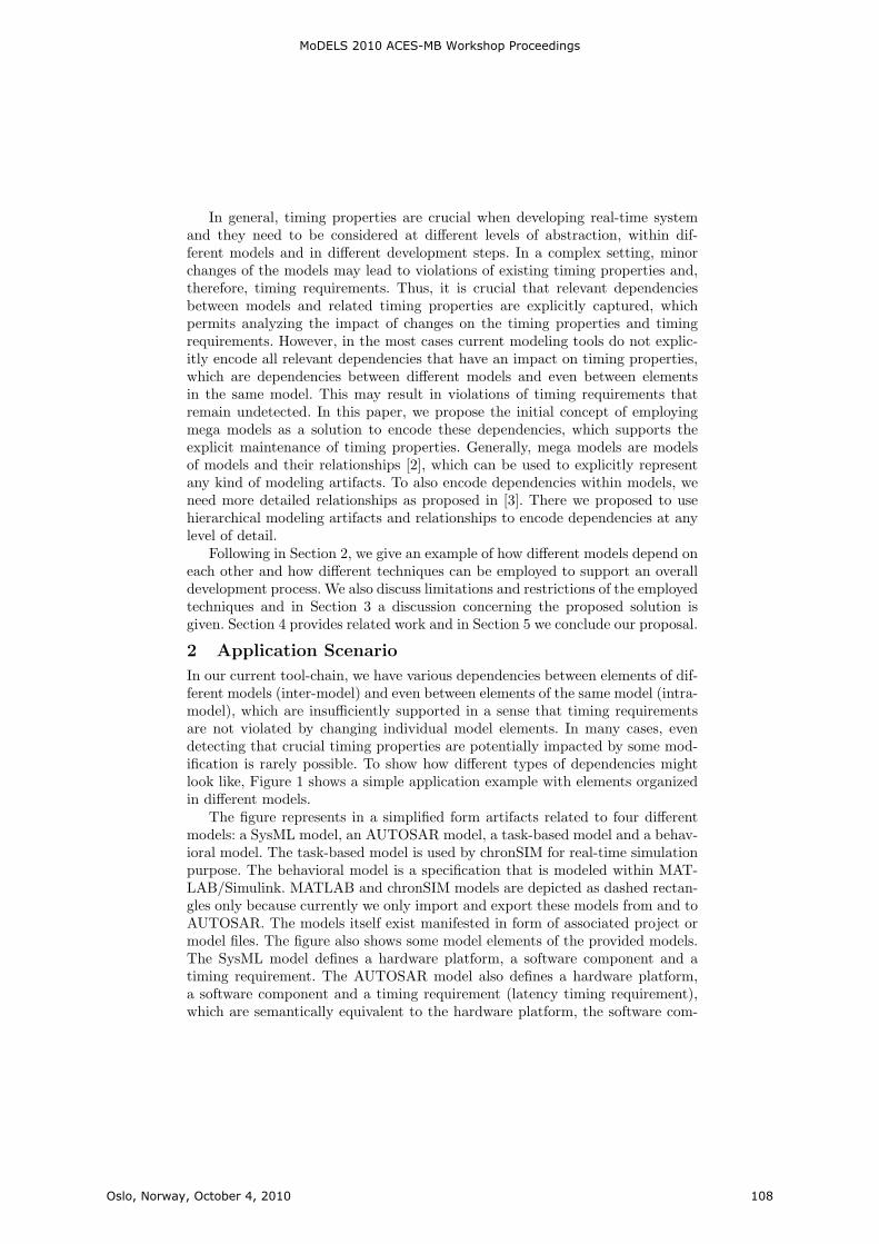
In general, timing properties are crucial when developing real-time systemand they need to be considered at different levels of abstraction, within dif-ferent models and in different development steps. In a complex setting, minorchanges of the models may lead to violations of existing timing properties and,therefore, timing requirements. Thus, it is crucial that relevant dependenciesbetween models and related timing properties are explicitly captured, whichpermits analyzing the impact of changes on the timing properties and timingrequirements. However, in the most cases current modeling tools do not explic-itly encode all relevant dependencies that have an impact on timing properties,which are dependencies between different models and even between elementsin the same model. This may result in violations of timing requirements thatremain undetected. In this paper, we propose the initial concept of employingmega models as a solution to encode these dependencies, which supports theexplicit maintenance of timing properties. Generally, mega models are modelsof models and their relationships [2], which can be used to explicitly representany kind of modeling artifacts. To also encode dependencies within models, weneed more detailed relationships as proposed in [3]. There we proposed to usehierarchical modeling artifacts and relationships to encode dependencies at anylevel of detail.
Following in Section 2, we give an example of how different models depend oneach other and how different techniques can be employed to support an overalldevelopment process. We also discuss limitations and restrictions of the employedtechniques and in Section 3 a discussion concerning the proposed solution isgiven. Section 4 provides related work and in Section 5 we conclude our proposal.
2 Application Scenario
In our current tool-chain, we have various dependencies between elements of dif-ferent models (inter-model) and even between elements of the same model (intra-model), which are insufficiently supported in a sense that timing requirementsare not violated by changing individual model elements. In many cases, evendetecting that crucial timing properties are potentially impacted by some mod-ification is rarely possible. To show how different types of dependencies mightlook like, Figure 1 shows a simple application example with elements organizedin different models.
The figure represents in a simplified form artifacts related to four differentmodels: a SysML model, an AUTOSAR model, a task-based model and a behav-ioral model. The task-based model is used by chronSIM for real-time simulationpurpose. The behavioral model is a specification that is modeled within MAT-LAB/Simulink. MATLAB and chronSIM models are depicted as dashed rectan-gles only because currently we only import and export these models from and toAUTOSAR. The models itself exist manifested in form of associated project ormodel files. The figure also shows some model elements of the provided models.The SysML model defines a hardware platform, a software component and atiming requirement. The AUTOSAR model also defines a hardware platform,a software component and a timing requirement (latency timing requirement),which are semantically equivalent to the hardware platform, the software com-
MoDELS 2010 ACES-MB Workshop Proceedings
Oslo, Norway, October 4, 2010 108
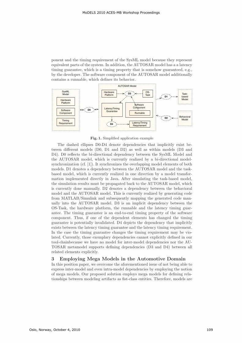
ponent and the timing requirement of the SysML model because they representequivalent parts of the system. In addition, the AUTOSAR model has a a latencytiming guarantee, which is a timing property that is somehow guaranteed, e.g.,by the developer. The software component of the AUTOSAR model additionallycontains a runnable, which defines its behavior.
AUTOSAR Model
SoftwareComponent
HardwarePlatform
OS-Task
Runnable
LatencyTimingRequirement
LatencyTimingGuarantee
SysMLModel
SoftwareComponent
HardwarePlatform
TimingRequirement
D0
Task-basedModel
D1
D4
D3
BehavioralModel
D2
Fig. 1. Simplified application example
The dashed ellipses D0-D4 denote dependencies that implicitly exist be-tween different models (D0, D1 and D2) as well as within models (D3 andD4). D0 reflects the bi-directional dependency between the SysML Model andthe AUTOSAR model, which is currently realized by a bi-directional model-synchronization (cf. [1]). It synchronizes the overlapping model elements of bothmodels. D1 denotes a dependency between the AUTOSAR model and the task-based model, which is currently realized in one direction by a model transfor-mation implemented directly in Java. After simulating the task-based model,the simulation results must be propagated back to the AUTOSAR model, whichis currently done manually. D2 denotes a dependency between the behavioralmodel and the AUTOSAR model. This is currently realized by generating codefrom MATLAB/Simulink and subsequently mapping the generated code man-ually into the AUTOSAR model. D3 is an implicit dependency between theOS-Task, the hardware platform, the runnable and the latency timing guar-antee. The timing guarantee is an end-to-end timing property of the softwarecomponent. Thus, if one of the dependent elements has changed the timingguarantee is potentially invalidated. D4 depicts the dependency that implicitlyexists between the latency timing guarantee and the latency timing requirement.In the case the timing guarantee changes the timing requirement may be vio-lated. Currently, those exemplary dependencies cannot explicitly defined in ourtool-chainbecause we have no model for inter-model dependencies nor the AU-TOSAR metamodel supports defining dependencies (D3 and D4) between allrelated elements explicitly.
3 Employing Mega Models in the Automotive DomainIn this position paper, we overcome the aforementioned issue of not being able toexpress inter-model and even intra-model dependencies by employing the notionof mega models. Our proposed solution employs mega models for defining rela-tionships between modeling artifacts as fist-class entities. Therefore, models are
MoDELS 2010 ACES-MB Workshop Proceedings
Oslo, Norway, October 4, 2010 109
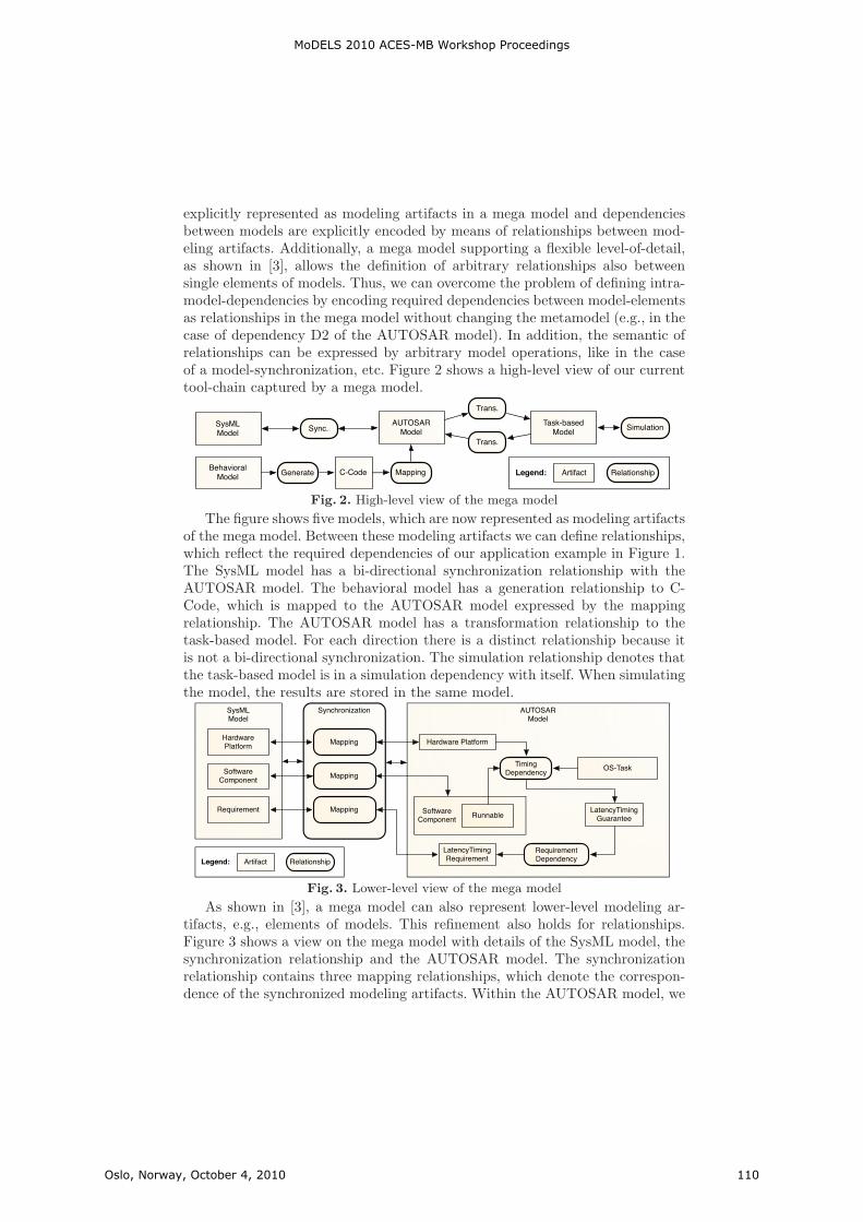
explicitly represented as modeling artifacts in a mega model and dependenciesbetween models are explicitly encoded by means of relationships between mod-eling artifacts. Additionally, a mega model supporting a flexible level-of-detail,as shown in [3], allows the definition of arbitrary relationships also betweensingle elements of models. Thus, we can overcome the problem of defining intra-model-dependencies by encoding required dependencies between model-elementsas relationships in the mega model without changing the metamodel (e.g., in thecase of dependency D2 of the AUTOSAR model). In addition, the semantic ofrelationships can be expressed by arbitrary model operations, like in the caseof a model-synchronization, etc. Figure 2 shows a high-level view of our currenttool-chain captured by a mega model.
SysMLModel
AUTOSARModel
Task-basedModel
BehavioralModel
Sync. Simulation
Trans.
Mapping Artifact RelationshipLegend:
Trans.
C-CodeGenerate
Fig. 2. High-level view of the mega model
The figure shows five models, which are now represented as modeling artifactsof the mega model. Between these modeling artifacts we can define relationships,which reflect the required dependencies of our application example in Figure 1.The SysML model has a bi-directional synchronization relationship with theAUTOSAR model. The behavioral model has a generation relationship to C-Code, which is mapped to the AUTOSAR model expressed by the mappingrelationship. The AUTOSAR model has a transformation relationship to thetask-based model. For each direction there is a distinct relationship because itis not a bi-directional synchronization. The simulation relationship denotes thatthe task-based model is in a simulation dependency with itself. When simulatingthe model, the results are stored in the same model.
SysMLModel
AUTOSARModel
Synchronization
Hardware Platform
OS-Task
Runnable
LatencyTimingRequirement
TimingDependency
LatencyTimingGuarantee
RequirementDependency
SoftwareComponent
Mapping
HardwarePlatform
Mapping
Artifact RelationshipLegend:
Requirement Mapping SoftwareComponent
Fig. 3. Lower-level view of the mega model
As shown in [3], a mega model can also represent lower-level modeling ar-tifacts, e.g., elements of models. This refinement also holds for relationships.Figure 3 shows a view on the mega model with details of the SysML model, thesynchronization relationship and the AUTOSAR model. The synchronizationrelationship contains three mapping relationships, which denote the correspon-dence of the synchronized modeling artifacts. Within the AUTOSAR model, we
MoDELS 2010 ACES-MB Workshop Proceedings
Oslo, Norway, October 4, 2010 110
can now explicitly encode the dependencies of the elements that directly impactthe latency timing guarantee (timing dependency) as well as the dependency thatdirectly impacts the latency timing requirement (requirement dependency).
A prerequisite for implementing this solution is a platform like Eclipse in com-bination with EMF (see http://www.eclipse.org/emf), which is responsiblefor hosting all models in central workspace. If all required artifacts are accessiblein that workspace, we can easily represent all required modeling artifacts withinthe mega model and relate them appropriately.
4 Related WorkDue to the lack of space, we will only briefly discuss two different approachesrelated to our proposal. In [4] an approach called ModelBus is described thatintegrates tools through adapters to bridge different technologies. Their focus ison orchestrating the development process through modeling services provided bydiverse tools. Thus, their approach is process oriented but not model oriented.We want to focus on a generic model (mega model) that represents modelingartifacts of different tools and further maintains relationships between thesemodels on the basis of the generic model. Nevertheless, ModelBus can potentiallybe combined with our approach by employing its adapter capabilities.
DUALLY [5] is a framework for the support of language and tool inter-operability by providing mechanisms to specify dependencies between different(meta) models. Based on these dependencies model transformations can be auto-matically derived. While we understand model transformation and also model-synchronization (like described in [6]) as a key concept to be used to obtaininteroperability between different models, intra-model dependencies are rarelysupported by the transformations used in DUALLY.
5 ConclusionsIn this paper, we proposed a shift from a tool oriented solution to a modeloriented solution to manage the dependencies concerning real-time propertiesbetween models in different tools as well between model elements included in thesame tool or model. Therefore, we suggest applying mega models for capturingmodeling artifacts and dependencies in between. On top of the mega models, wecan formally reason about dependencies but also apply impact analysis, etc.
References
1. Giese, H., Hildebrandt, S., Neumann, S.: Towards Integrating SysML and AUTOSAR Modelingvia Bidirectional Model Synchronization. In: 5th Workshop on Model-Based Development ofEmbedded Systems (MBEES). (2009)
2. Bezivin, J., Jouault, F., Valduriez, P.: On the Need for Megamodels. In: Proc of the OOPSLA/G-PCE: Best Practices for Model-Driven Software Development workshop, 19th Annual ACM Con-ference on Object-Oriented Programming, Systems, Languages, and Applications. (2004)
3. Seibel, A., Neumann, S., Giese, H.: Dynamic Hierarchical Mega Models: Comprehensive Trace-ability and its Efficient Maintenance. Software and System Modeling 009(s10270) (2009)
4. Aldazabal, A., Baily, T., Nanclares, F., Sadovykh, A., Hein, C., Ritter, T.: Automated modeldriven development processes. In: ECMDA - Tools and Process Integration Workshop, Berlin,June. (2008)
5. Malavolta, I., Muccini, H., Pelliccione, P., Tamburri, D.A.: Providing Architectural Languagesand Tools Interoperability through Model Transformation Technologies. IEEE Transactions onSoftware Engineering 36(1) (January/February 2010)
6. Giese, H., Wagner, R.: From model transformation to incremental bidirectional model synchro-nization. Software and Systems Modeling 8(1) (1 February 2009)
MoDELS 2010 ACES-MB Workshop Proceedings
Oslo, Norway, October 4, 2010 111

A Transformation-Based Model of Evolutionary
Architecting for Embedded System Product Lines
Jakob Axelsson
School of Innovation, Design and Engineering, Mälardalen University, SE-721 23 Västerås, Sweden
Abstract. In many industries, embedded software plays an increasingly important role in defining the characteristics of the products. Often, a product line approach is used, and the system architecture is developed through evolution rather than being redone from scratch for each product. In this paper, we present a model of such an evolutionary process based on architecture transformations. The model attempts to give an accurate description of how real architects actually work. Key elements of the approach are how the transformations interact with consistency constraints and with feasibility in terms of resource limitations. The work is based on findings from previous case studies in the automotive industry. The model can be used to enhance our understanding of the architecting process, and to find ways to improve it.
Keywords: Architecture, embedded systems, evolution, transformations.
1 Introduction
The increasing complexity of embedded systems leads to soaring development costs, and many companies strive to curb this trend by reusing software and hardware between products through a product line approach. This makes architecture very important, and we have previously done in-depth studies of the architecting practices at a some companies (see e.g. [6]), showing that instead of following a well-defined process and method, the architects base their work on experience and gut feeling. Academic literature on architecting is mostly concerned with developing a new system from scratch, something that rarely occurs in the organizations mentioned above. We term this traditional approach revolutionary architecting, and we have previously argued based on another case study that the focus should instead be on the evolutionary architecting where a new version of an existing product is developed [1]. To systematically attack the problem of lacking processes and methods for architecting, there is a need to provide a description of how architects work today. The research question of this paper is therefore: What is a suitable model for capturing how evolutionary architecting is performed in organizations developing complex embedded system? The contribution of the paper is to propose such a model, which is based on transformations of an architectural description and related analyses. Using this model, it becomes possible to reason about aspects of the architect's work and to describe phenomena encountered during empirical research on architecting.
MoDELS 2010 ACES-MB Workshop Proceedings
Oslo, Norway, October 4, 2010 113

2 Evolutionary architecting and architecture descriptions
In the evolutionary process, architecting is triggered by a product change request. The architects get input in terms of requirements primarily from the function developers. The architects then try to design a high-level technical solution, focusing on the distribution of functionality onto different systems, and on the interfaces between systems. When designing the high-level solution and evaluating alternatives, they take into account not only the requirements, but also architectural quality attributes, which are properties of the architecture itself which they strive to maintain. Throughout the work, the architects create descriptions of the architecture. The descriptions are used to define pre-requisites for the system developers.
The architect primarily focuses on resolving issues that go across several subsystems, and this entails dealing with the following concerns:
• Feasibility, i.e. possibility to implement the functionality by the available computational resources.
• Consistency, i.e. that all interfaces between parts are well defined.
• Optimality, in terms of important quality attributes (including cost).
• Modifiability, to enable future evolution.
The model presented here attempts to describe what information the architects deal with in their work. That information might appear in many forms: formal models, sketches, texts, or just as mental models inside the architect's head. Our model tries to capture the essence of that information, and disregard its representation.
For modeling the architecture descriptions for embedded systems, it suffices with a metamodel (M2 level) that is essentially an annotated graph, containing elements of different kinds; relations between pairs of elements or between pairs of relations; and attributes describing properties of elements and of relations.
For distributed, embedded systems, a model (M1 level) for describing the architecture can be grouped into several levels of abstraction. In this paper, we will use four different views, whose elements and relations are shown in Table 1. (The description is similar to that provided in [2], except that the cluster level is implicitly captured through the allocation relations. Also, the physical packaging level is added in this paper, and the task level is excluded since it is internal to an ECU.) There are also relations between entities in different views, indicating which modules realize each function, how modules are allocated to ECU:s, where hardware elements and external entities are positioned, and how communication is routed.
The metamodel allows attributes on elements and relations describing their properties. For architects, the primary properties have to do with desired qualities and limited resources present. The desired qualities are those properties that the architect tries to optimize when selecting among alternative feasible solutions. One of the most important ones is cost, which can be further divided into product cost and development cost. The product cost is essentially the cost of hardware, so we add a product cost attribute to each element of the hardware view. Important resources are present in ECUs (processing capacity, memory size, I/O pins), communication channels (bandwidth), and spaces and routing channels (volume).
MoDELS 2010 ACES-MB Workshop Proceedings
Oslo, Norway, October 4, 2010 114
Table 1. Views, elements, and relations in architecture descriptions.
View Element Relations within view
Functional Function External entity
Functional dependency
Logical Module Data flow
Hardware ECU Sensor Actuator Comm. channel
Signal flow
Positioning Space Routing channel
Connection
Architects do usually not make complete models of the entire architecture, but
rather only describe those parts which are relevant to resolve a certain change request. Therefore, we should not assume that we are dealing with complete information. However, among those elements related to the change request, consistency must be reached so that for instance all necessary relations are present. As an example, if the change is to add a new function, which is realized by a certain set of modules, all those modules must be allocated to ECUs, and none can be left dangling.
3 Transformations and analyses
We believe that the essence of the architect's work can be captured as a sequence of transformations of the architectural description (on the instance, or M0, level), together with analyses to see that the solution is feasible, cost efficient, and future proof. Just as the architecture descriptions can take many forms, including mental models, the transformations can in reality be explicit or very implicit.
There are two basic transformations on the metamodel level: add entity and remove entity. Since the entities are either elements or relations, the possible transformations become add element, remove element, add relation, and remove relation. At the model level, these abstract transformations can be made concrete, resulting in, e.g., add module, remove ECU.
Sometimes architects also use composite transformations. A good example is change relation, which basically consists of add relation1 followed by remove
relation2. A concrete example is when a module that used to be allocated to one ECU is moved to another ECU by a change allocation transformation. Other composites are change element (e.g. change ECU to, e.g., an upgraded processor); split element (e.g., split module when a software module is divided to allow distribution); and the reciprocal merge element. Through the composite relations, we end up with a formal language which is very close to the natural language used by architects during their daily work.
As described in Section 2, the architect's work is triggered by a change request to an existing architecture, which is consistent and feasible. This change request can be
MoDELS 2010 ACES-MB Workshop Proceedings
Oslo, Norway, October 4, 2010 115
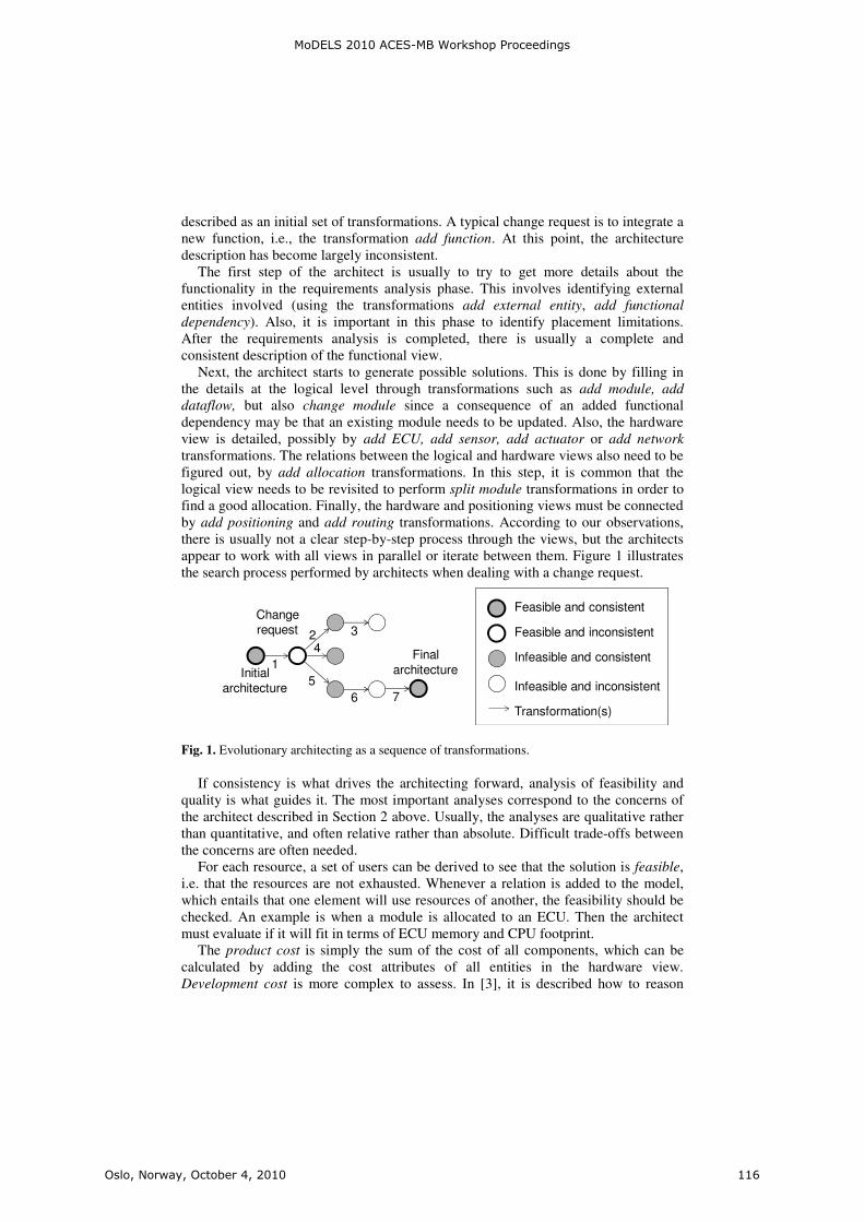
described as an initial set of transformations. A typical change request is to integrate a new function, i.e., the transformation add function. At this point, the architecture description has become largely inconsistent.
The first step of the architect is usually to try to get more details about the functionality in the requirements analysis phase. This involves identifying external entities involved (using the transformations add external entity, add functional
dependency). Also, it is important in this phase to identify placement limitations. After the requirements analysis is completed, there is usually a complete and consistent description of the functional view.
Next, the architect starts to generate possible solutions. This is done by filling in the details at the logical level through transformations such as add module, add
dataflow, but also change module since a consequence of an added functional dependency may be that an existing module needs to be updated. Also, the hardware view is detailed, possibly by add ECU, add sensor, add actuator or add network transformations. The relations between the logical and hardware views also need to be figured out, by add allocation transformations. In this step, it is common that the logical view needs to be revisited to perform split module transformations in order to find a good allocation. Finally, the hardware and positioning views must be connected by add positioning and add routing transformations. According to our observations, there is usually not a clear step-by-step process through the views, but the architects appear to work with all views in parallel or iterate between them. Figure 1 illustrates the search process performed by architects when dealing with a change request.
Fig. 1. Evolutionary architecting as a sequence of transformations.
If consistency is what drives the architecting forward, analysis of feasibility and quality is what guides it. The most important analyses correspond to the concerns of the architect described in Section 2 above. Usually, the analyses are qualitative rather than quantitative, and often relative rather than absolute. Difficult trade-offs between the concerns are often needed.
For each resource, a set of users can be derived to see that the solution is feasible, i.e. that the resources are not exhausted. Whenever a relation is added to the model, which entails that one element will use resources of another, the feasibility should be checked. An example is when a module is allocated to an ECU. Then the architect must evaluate if it will fit in terms of ECU memory and CPU footprint.
The product cost is simply the sum of the cost of all components, which can be calculated by adding the cost attributes of all entities in the hardware view. Development cost is more complex to assess. In [3], it is described how to reason
Feasible and consistent
Feasible and inconsistent
Infeasible and consistent
Infeasible and inconsistent
Transformation(s)
Initial
architecture
Change
request
1
5
42 3
76
Final
architecture
MoDELS 2010 ACES-MB Workshop Proceedings
Oslo, Norway, October 4, 2010 116
about the cost for software changes. The approach is to first identify which modules change, and then either simply count how many modules are touched, or try to perform a more refined analysis or initiated guess of the magnitude of change.
The architects also try to keep in mind that the architecture should be modifiable. However, as pointed out in [5], it is not meaningful to reason about modifiability as such, but only how modifiable the architecture is with respect to a certain class of changes. For embedded systems, a common barrier to modification is lack of hardware resources. The architects try to strike a balance between adding surplus resources to the hardware for future growth, and optimizing the resources in order to reduce product cost. This kind of reasoning can be thought of as a real options analysis [4]. In such an analysis, the main difficulty is to estimate the likelihood of certain types of changes. If architects keep track of how frequent certain transformations are, they can extrapolate more reliable figures. The transformation model thus gives the architect a language for capturing knowledge about changes.
4 Conclusions
In this paper, we have outlined a Transformation-based Evolutionary Architecting Model (TEAM), which attempts to describe essential knowledge about how real architects go about developing embedded system product lines. The basis is data collected from observing real architecting work, and we have attempted to construct a model with a high fidelity in the sense that the language the architects use to describe their own process should be possible to map to the model.
Although the model presented in the paper is largely based on experiences from the automotive domain, the fundamental ideas are captured in the metamodel which is much more general and allows many different views and elements to be included.
References
1. Axelsson, J. Evolutionary architecting of embedded automotive product lines: An industrial case study. In Proc. Joint 8th Working IEEE/IFIP Conf. on Software Architecture & 3rd European Conf. on Software Architecture, pp. 101-110. Cambridge, UK, Sept. 14-17, 2009.
2. Broy, M., Krüger, I., Pretschner, A., and Salzmann, C. Engineering Automotive Software. Proc. IEEE, Vol. 95, Issue 2, pp. 356-373, Feb. 2007.
3. Eden, A. H. and Mens, T. Measuring Software Flexibility. IEE Software, Vol. 153, Issue 3, pp. 113-126, June 2006.
4. Gustavsson, H. and Axelsson, J. Evaluating Flexibility in Embedded Automotive Product Lines Using Real Options. In Proc. 12th Intl. Software Product Line Conf., pp. 235-242. Limerick, Ireland, Sept. 8-12, 2008.
5. Parnas, D. L. Software aging. In Proc. Intl. Conf. Software Engineering, pp. 279-287. Sorrento, Italy, 1994.
6. Wallin, P. and Axelsson, J. A case study of issues related to automotive E/E system architecture development. In Proc. 15th IEEE Intl. Conf. on Engineering of Computer Based Systems, pp. 87-95. Belfast, Northern Ireland, March 31-April 4, 2008.
MoDELS 2010 ACES-MB Workshop Proceedings
Oslo, Norway, October 4, 2010 117


Identifying Features for Ground Vehicles SoftwareProduct Lines by Means of Annotated Models
Rafael S. Durelli1,†,‡, Daniel B. F. Conrado1,†, Ricardo Argenton Ramos2,§, OscarLopez Pastor3,§, Valter V. de Camargo1,†,§, and Rosangela A. D. Penteado1,†,§
1 Computing Dept., Federal University of Sao Carlos, Sao Carlos – Sao Paulo – Brazil{rafael_durelli,daniel_conrado,valter,rosangela}@dc.ufscar.br
2 Collegiate of Computer Engineering, Federal University of Vale do Sao Francisco, Juazeiro –Bahia – Brazil
[email protected] Dept. of Computer Systems and Computation, Universidad Politecnica de Valencia, Valencia
Abstract. An approach for the identification of features supported by class mod-els annotated with stereotypes is shown in this paper. The models are automat-ically reverse engineered by a tool called Rejasp/Dmasp where attributes andmethods are stereotyped if they have some relation with candidate features. Theapproach consists of four guidelines and focuses on identifying features in em-bedded systems of ground vehicles. As a preliminary evaluation, the guidelineswere applied in creating a product line in the domain of ground vehicles.
Keywords: Software Product Line, Embedded Systems, Ground Vehicles
1 Introduction
Software Product Line (SPL) enables systems to be developed quickly through the com-position of reusable artifacts [2], that is, in other words, the software – a product linemember or product – is developed by composing features of a specific domain [7]. Fea-tures are abstractions of design and code that represent the variability of a domain andmay be optional, alternative or mandatory.
In general, the development of Embedded Systems (ES) is not supported by sys-tematic techniques of reuse, leading to bad time-to-market and low quality of products.Previous studies have explored the use of SPL techniques for developing embedded sys-tems aiming at increasing productivity and quality of these systems [3,4,6]. Howevernone of these papers present clear guidelines or support tools for the agile identificationof features for rapid development of SPL in a fast way [5].
Most researchers in the literature do not provide explicit guidelines for the identifi-cation of features to build product lines of ES. Recent research such as Mohan et al [5]
† Financial support provided by CNPq and FAPESP under INCT-SEC processes 573963/2008-8 and 08/57870-9 respectly.‡ Financial support provided by Capes.§ Financial support provided by CNPq – Projeto Universal – Process no 483106/2009-7.
MoDELS 2010 ACES-MB Workshop Proceedings
Oslo, Norway, October 4, 2010 119
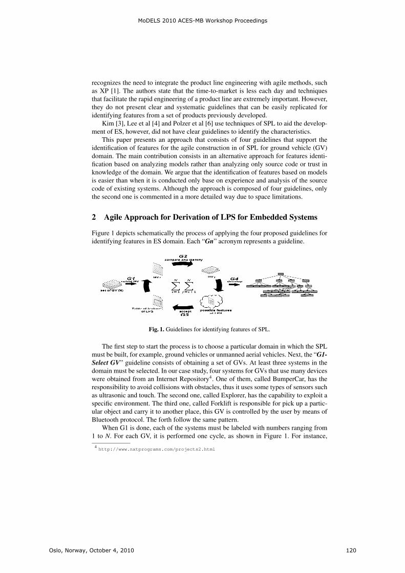
recognizes the need to integrate the product line engineering with agile methods, suchas XP [1]. The authors state that the time-to-market is less each day and techniquesthat facilitate the rapid engineering of a product line are extremely important. However,they do not present clear and systematic guidelines that can be easily replicated foridentifying features from a set of products previously developed.
Kim [3], Lee et al [4] and Polzer et al [6] use techniques of SPL to aid the develop-ment of ES, however, did not have clear guidelines to identify the characteristics.
This paper presents an approach that consists of four guidelines that support theidentification of features for the agile construction in of SPL for ground vehicle (GV)domain. The main contribution consists in an alternative approach for features identi-fication based on analyzing models rather than analyzing only source code or trust inknowledge of the domain. We argue that the identification of features based on modelsis easier than when it is conducted only base on experience and analysis of the sourcecode of existing systems. Although the approach is composed of four guidelines, onlythe second one is commented in a more detailed way due to space limitations.
2 Agile Approach for Derivation of LPS for Embedded Systems
Figure 1 depicts schematically the process of applying the four proposed guidelines foridentifying features in ES domain. Each “Gn” acronym represents a guideline.
Fig. 1. Guidelines for identifying features of SPL.
The first step to start the process is to choose a particular domain in which the SPLmust be built, for example, ground vehicles or unmanned aerial vehicles. Next, the “G1-Select GV” guideline consists of obtaining a set of GVs. At least three systems in thedomain must be selected. In our case study, four systems for GVs that use many deviceswere obtained from an Internet Repository4. One of them, called BumperCar, has theresponsibility to avoid collisions with obstacles, thus it uses some types of sensors suchas ultrasonic and touch. The second one, called Explorer, has the capability to exploit aspecific environment. The third one, called Forklift is responsible for pick up a partic-ular object and carry it to another place, this GV is controlled by the user by means ofBluetooth protocol. The forth follow the same pattern.
When G1 is done, each of the systems must be labeled with numbers ranging from1 to N. For each GV, it is performed one cycle, as shown in Figure 1. For instance,
4http://www.nxtprograms.com/projects2.html
MoDELS 2010 ACES-MB Workshop Proceedings
Oslo, Norway, October 4, 2010 120
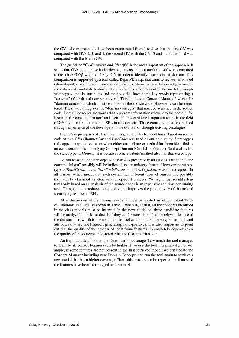
the GVs of our case study have been enumerated from 1 to 4 so that the first GV wascompared with GVs 2, 3, and 4; the second GV with the GVs 3 and 4 and the third wascompared with the fourth GV.
The guideline “G2-Compare and Identify” is the most important of the approach. Itstates that GVi should have its hardware (sensors and actuator) and software comparedto the others GVsj, where i+1 ≤ j ≤ N, in order to identify features in this domain. Thiscomparison is supported by a tool called Rejasp/Dmasp, that aims to recover annotated(stereotyped) class models from source code of systems, where the stereotypes meansindications of candidate features. These indications are evident in the models throughstereotypes, that is, attributes and methods that have some key words representing a“concept” of the domain are stereotyped. This tool has a “Concept Manager” where the“domain concepts” which must be mined in the source code of systems can be regis-tered. Thus, we can register the “domain concepts” that must be searched in the sourcecode. Domain concepts are words that represent information relevant to the domain, forinstance, the concepts “motor” and “sensor” are considered important terms in the fieldof GV and can be features of a SPL in this domain. These concepts must be obtainedthrough experience of the developers in the domain or through existing ontologies.
Figure 2 depicts parts of class diagrams generated by Rejasp/Dmasp based on sourcecode of two GVs (BumperCar and LineFollower) used as our case study. Stereotypesonly appear upper class names when either an attribute or method has been identified asan occurrence of the underlying Concept Domain (Candidate Feature). So if a class hasthe stereotype �Motor� it is because some attribute/method also has that stereotype.
As can be seen, the stereotype �Motor� is presented in all classes. Due to that, theconcept “Motor” possibly will be indicated as a mandatory feature. However the stereo-type �TouchSensor�, �UltraSonicSensor� and �LightSensor� do not appear inall classes, which means that each system has different types of sensors and possiblythey will be classified as alternative or optional features. We argue that identify fea-tures only based on an analysis of the source codes is an expensive and time consumingtask. Thus, this tool reduces complexity and improves the productivity of the task ofidentifying features of SPL.
After the process of identifying features it must be created an artifact called Tableof Candidate Features, as shown in Table 1, wherein, at first, all the concepts identifiedin the class models must be inserted. In the next guideline, these candidate featureswill be analyzed in order to decide if they can be considered final or relevant feature ofthe domain. It is worth to mention that the tool can annotate (stereotype) methods andattributes that are not features, generating false-positives. It is also important to pointout that the quality of the process of identifying features is completely dependent onthe quality of the concepts registered with the Concept Manager.
An important detail is that the identification coverage (how much the tool managesto identify all correct features) can be higher if we use the tool incrementaly. For ex-ample, if some features are not present in the first retrieved model, we can update theConcept Manager including new Domain Concepts and run the tool again to retrieve anew model that has a higher coverage. Then, this process can be repeated until most ofthe features have been stereotyped in the model.
MoDELS 2010 ACES-MB Workshop Proceedings
Oslo, Norway, October 4, 2010 121
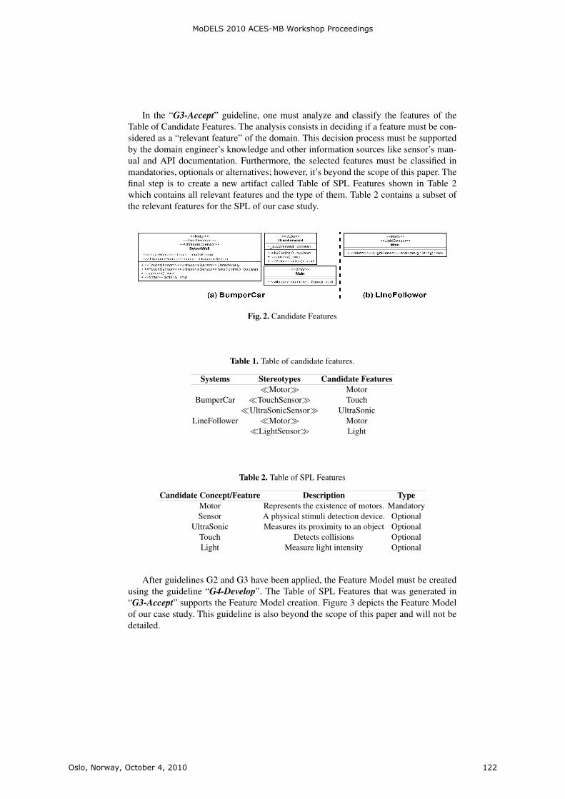
In the “G3-Accept” guideline, one must analyze and classify the features of theTable of Candidate Features. The analysis consists in deciding if a feature must be con-sidered as a “relevant feature” of the domain. This decision process must be supportedby the domain engineer’s knowledge and other information sources like sensor’s man-ual and API documentation. Furthermore, the selected features must be classified inmandatories, optionals or alternatives; however, it’s beyond the scope of this paper. Thefinal step is to create a new artifact called Table of SPL Features shown in Table 2which contains all relevant features and the type of them. Table 2 contains a subset ofthe relevant features for the SPL of our case study.
Fig. 2. Candidate Features
Table 1. Table of candidate features.
Systems Stereotypes Candidate Features�Motor� Motor
BumperCar �TouchSensor� Touch�UltraSonicSensor� UltraSonic
LineFollower �Motor� Motor�LightSensor� Light
Table 2. Table of SPL Features
Candidate Concept/Feature Description TypeMotor Represents the existence of motors. MandatorySensor A physical stimuli detection device. Optional
UltraSonic Measures its proximity to an object OptionalTouch Detects collisions OptionalLight Measure light intensity Optional
After guidelines G2 and G3 have been applied, the Feature Model must be createdusing the guideline “G4-Develop”. The Table of SPL Features that was generated in“G3-Accept” supports the Feature Model creation. Figure 3 depicts the Feature Modelof our case study. This guideline is also beyond the scope of this paper and will not bedetailed.
MoDELS 2010 ACES-MB Workshop Proceedings
Oslo, Norway, October 4, 2010 122

Fig. 3. The developed Feature Model.
3 Final Remarks
We argue that identify features only by means of experience and existing source code ismore costly and error prone than using a model-based approach like the one presentedby us. In our approach, models assist in an agile identification of domain concepts inseveral systems of a domain, which makes the identification of features a more con-trolled and productive task. The quality of the identified features depends on the set ofconcepts previously registered in Concept Manager of Rejasp/Dmasp. Therefore, wesuggest registering a concept list or a domain’s ontology in the tool.
We also argue that top-down strategies for feature identification, that is, those thatidentify features by analyzing a certain domain instead of systems previously devel-oped, are not suitable when the SPL must be created in a short time. The main cause isthat analyzing a domain usually takes a long time to be finished and yields a wide rangeof features that are not relevant or that may never be used to derive products from thePL.
As a future work, we intend to improve the proposed guidelines in order to be ap-plied in existing agile methods like XP or SCRUM.
References1. Beck, K., Andres, C.: Extreme Programming Explained: Embrace Change (2nd Edition).
Addison-Wesley Professional (2004)2. Clements, P., Northrop, L.: Software Product Lines. Addison-Wesley (2002)3. Kim, H.K.: Applying product line to the embedded systems. In: Computational Science and
Its Applications - ICCSA 2006. Springer (May 2006)4. Lee, J., Cho, J.H., Ham, D.H., Kim, J.S.: Methodology for embedded system development
based on product line. vol. 2, pp. 920 –923 (2005)5. Mohan, K., Ramesh, B., Sugumaran, V.: Integrating software product line engineering and
agile development. Software, IEEE 27(3), 48 –55 (may 2010)6. Polzer, A., Kowalewski, S., Botterweck, G.: Applying software product line techniques in
model-based embedded systems engineering. In: MOMPES ’09: Proceedings of the 2009ICSE Workshop on Model-Based Methodologies for Pervasive and Embedded Software. pp.2–10. IEEE Computer Society, Washington, DC, USA (2009)
7. Weiss, D.M., Chi: Software Product-Line Engineering: A Family-Based Software Develop-ment Process. Addison-Wesley Professional; Har/Cdr edition (1999)
MoDELS 2010 ACES-MB Workshop Proceedings
Oslo, Norway, October 4, 2010 123


Product Line Development using MultipleDomain Specific Languages in Embedded
Systems
Susumu Tokumoto
Fujitsu Laboratories Limited, Software & Solution Laboratories,4-1-1, Kamikodanaka, Nakahara-ku, Kawasaki-shi, Kanagawa, Japan
http://jp.fujitsu.com
Abstract. In model driven development (MDD), much meaning can begiven to the model using a domain specific language (DSL), and the codegeneration rate can be increased. Model-based product line developmentis possible using code generation to realize variability. In this paper, wedescribe the development of line tracer robots for a contest, where weachieved a high rate of code generation by using two DSLs, the charac-teristics of which supplement each other. Structure is described by a highgenerality DSL and behavior by a high specificity DSL. Furthermore, var-ious kinds of products were able to be developed from one product lineefficiently by using code generation from two DSLs to realize variability.
Keywords: Domain Specific Language, Model Driven Development, Soft-ware Product Line
1 Introduction
In recent years, due to the diversification, intensification, and complexificationof user and market needs, the ability to rapidly provide various types of productshas become an important competitive advantage. Software product line (SPL)is one approach to solving such issues. SPL is a method for developing a varietyof products efficiently by reusing the common parts of the product line as a coreasset and switching the individual parts of each products as a variation pointwhich capability is called variability.
One technique for effective reuse is to incorporate model driven development(MDD) based on the SPL component meta model. [1]
We have worked on the effective development of a variety of products by usingtwo or more domain specific languages (DSL) to design models, where each DSLallows different variabilities to be realized its model. A high code generationrate was achieved by gradually raising the degree of the domain specificity ofthe DSLs, synchronized with the progress of the development process.
MoDELS 2010 ACES-MB Workshop Proceedings
Oslo, Norway, October 4, 2010 125

2 Susumu Tokumoto
2 Problems
2.1 Problem of variability over various kinds of products
In SPL, code generation is a technique for realizing variability. If variability isexpressible in the model, a system can be constructed with a high tolerance formodifications and derivations.
However, in the case that source code is generated from a DSL description, ifvariabilities are not expressible in the DSL’s specified domain, these variabilitiescannot be realized by the code generation, and a different technique of realizingvariability should be chosen (left side of Fig.1), e.g., structural DSL cannotrealize variability of behavior.
It becomes a problem when considering many kinds of products because thevariability that can be realized from one DSL is limited.
Fig. 1. Problem of variability over various kinds of products
2.2 Problem of code generation rate and generality
Generally, a DSL with low generality can achieve a high code generation ratebecause a lot of information of the specified domain is added to the meta modelof the DSL, but projects that can use the DSL are limited to ones that suit thedomain. On the other hand, a DSL for which generality is high might have alower code generation rate because little information of the specified domain isadded to the meta model of the DSL. There is a trade-off relating to the degreeof code generation rate and that of domain specificity, and it is difficult to satisfyboth.
3 Solutions
To solve the problems described in the preceding chapter, we propose a devel-opment process that uses two or more DSLs.
1. Define products that apply SPL, and analyze variabilities.
MoDELS 2010 ACES-MB Workshop Proceedings
Oslo, Norway, October 4, 2010 126
Product Line Development using Multiple DSLs in Embedded Systems 3
2. Select or design a DSL that can achieve variabilities. It is not necessary toconsider all the variabilities. Raise the degree of the domain specificity ofthe adopted DSL as the development process advances. As a result, the codegeneration rate is raised.
3. Implement the DSL tool (if a new DSL was necessary).4. Design a product with the adopted DSL while considering variabilities that
remain.5. If the product design is not complete, return to step 2.
The idea is to describe the outline with a high generality DSL, and to gen-erate the code where the domain dependency is small in the early stage of thedevelopment process. As the development process advances, adopt a higher do-main specificity DSL, and generate code which was not able to be generated atthe early stage. In such a development process, by using multiple mutually sup-plementing DSLs, a high code generation rate is achievable and the variabilityof many kinds of products is expressible with tolerance for modifications. (rightside of Fig.1).
4 Case study
The proposed process was applied in the development of line tracer robots forthe Embedded Technology Software Design Robot Contest (ET Robot Contest).[2]
4.1 Realizing variabilities by two DSLs
In ET Robot Contest 2009, two kinds of robots, an RCX (LEGO MINDSTORMSRCX) of four-wheel type and an NXT (LEGO MINDSTORMS NXT) of two-wheel inverted pendulum type, could be selected from. We entered both an NXTteam and RCX team.
There are only minor differences in the basic rules between NXT and RCX, sorequired functions are almost the same. Accordingly, we regarded unique parts,such as sensors and actuators, as variation points and the rest as core assets forreuse in both types of robots.
Furthermore, the contest required robots to run on both the inside and out-side lanes which have different features. Therefore, we considered the runningmethods that suit these features as variation points.
To realize these two aspects of variation points we use two DSLs. One is acomponentization DSL which realizes variability of structure; in other words, itdeals with differences between RCX and NXT parts. The other is a strategy DSLwhich realizes variability of behavior; in other words, it deals with differencesamong running methods.
The relation between the DSLs and the variabilities is shown in Fig.2.If, for example, it becomes necessary to add a new type of robot which has
a different sensor and actuator, the componentization DSL makes adding it tothe product line easy. Similarly if a different running method is needed, we canuse the strategy DSL to ease addition of it.
MoDELS 2010 ACES-MB Workshop Proceedings
Oslo, Norway, October 4, 2010 127
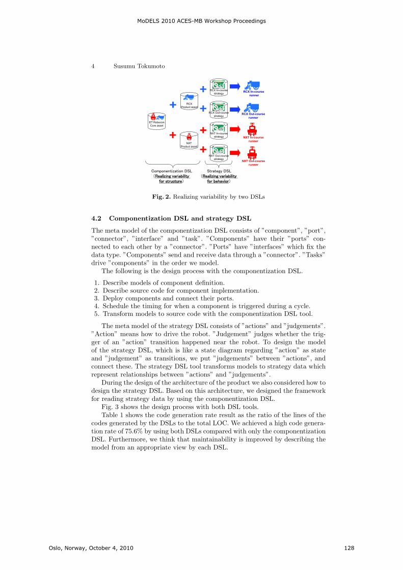
4 Susumu Tokumoto
NXT
Product asset
RCX
Product asset
ET Robocon
Core asset
RCX Out-course
runner
NXT In-course
runner
RCX In-course
strategy
RCX Out-course
strategy
NXT In-course
strategy
NXT Out-course
strategy
RCX In-course
runner
NXT Out-course
runner
Fig. 2. Realizing variability by two DSLs
4.2 Componentization DSL and strategy DSL
The meta model of the componentization DSL consists of ”component”, ”port”,”connector”, ”interface” and ”task”. ”Components” have their ”ports” con-nected to each other by a ”connector”. ”Ports” have ”interfaces” which fix thedata type. ”Components” send and receive data through a ”connector”. ”Tasks”drive ”components” in the order we model.
The following is the design process with the componentization DSL.
1. Describe models of component definition.2. Describe source code for component implementation.3. Deploy components and connect their ports.4. Schedule the timing for when a component is triggered during a cycle.5. Transform models to source code with the componentization DSL tool.
The meta model of the strategy DSL consists of ”actions” and ”judgements”.”Action” means how to drive the robot. ”Judgement” judges whether the trig-ger of an ”action” transition happened near the robot. To design the modelof the strategy DSL, which is like a state diagram regarding ”action” as stateand ”judgement” as transitions, we put ”judgements” between ”actions”, andconnect these. The strategy DSL tool transforms models to strategy data whichrepresent relationships between ”actions” and ”judgements”.
During the design of the architecture of the product we also considered how todesign the strategy DSL. Based on this architecture, we designed the frameworkfor reading strategy data by using the componentization DSL.
Fig. 3 shows the design process with both DSL tools.Table 1 shows the code generation rate result as the ratio of the lines of the
codes generated by the DSLs to the total LOC. We achieved a high code genera-tion rate of 75.6% by using both DSLs compared with only the componentizationDSL. Furthermore, we think that maintainability is improved by describing themodel from an appropriate view by each DSL.
MoDELS 2010 ACES-MB Workshop Proceedings
Oslo, Norway, October 4, 2010 128

Product Line Development using Multiple DSLs in Embedded Systems 5
����� ��� ����� � ����� ���
������� ����� ����������������� ��! "
# ��$���%�&�� � ����������������� ��! "
' � ()��� ���
*+(���,-(�. �/. �+�102� .�� ��� ( .435(++�76��98 � �/�:8 ��� ;-35��;+� �35(++�
����� ��� �1��=<���� �
*+(���,-(�. �/. �� �=,+> �4���4. � ����� (�.35(++�/? @-��.-A35(+ � .-��B
*)( �=,�� > �4�
C � ��.-8 0 (�� �
*+(���,+� > �
*+(���,-(�. �/. ��� D����� (�.E<1��F1� ()( >
����� ��� �1��=<���F1� ()( >
C � ��.-8 0 ( � �
Fig. 3. Process of design by componentization DSL and strategy DSL
Table 1. LOC generated by tools and code generation rate in RCX
generated by compo-nentization DSL
generated by compo-nentization DSL &strategy DSL
total LOC
LOC 4,567 5,422 7,173
Code generation rate 63.7% 75.6% -
5 Conclusion
In this paper, we proposed a product line development process using two ormore DSLs, and gave a case study of line tracer robot development to show therealization of variabilities of many kinds of products and achievement of a highcode generation rate.
Future work includes verification that the process can be scaled to allow usto build large-scale systems and evaluation that dealing with multiple DSLs forvariabilities can pay. The tools for multiple DSLs management might help latterproblem[3].
References
1. J.Kato, Y.Goto ”MDA in Product Line Engineering for Embedded Systems” Pro-ceedings of Embedded Systems Symposium 2007, pp. 54–63, 2007 (Japanese versiononly)
2. ET Robot Contest, http://www.etrobo.jp3. A.Hessellund, K.Czarnecki, A.Wasowski ”Guided Development with Multiple
Domain-Specific Languages” ACM/IEEE 10th International Conference on ModelDriven Engineering Languages and Systems, Nashville, Tennessee, 2007
MoDELS 2010 ACES-MB Workshop Proceedings
Oslo, Norway, October 4, 2010 129