Embed Size (px)
Citation preview

ENGLISH User Manual
AC/DC CURRENT PROBE MR417 MR527 99 Washington Street
Melrose, MA 02176 Phone 781-665-1400Toll Free 1-800-517-8431
Visit us at www.TestEquipmentDepot.com
Current Probe Models MR417/MR527 3
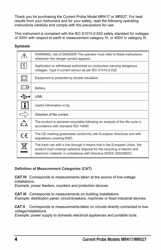
CONTENTS 1 DESCRIPTION……. ......................................................................................... 7
1.1 Interface .................................................................................................................. 8 1.1.1 MR417 ................................................................................................ 8 1.1.2 MR527 ................................................................................................ 9
2 OPERATION .................................................................................................. 10 2.1 Battery Installation ................................................................................................ 10 2.2 External Power (Optional).................................................................................... 10 2.3 Turning ON the Instrument .................................................................................. 11 2.4 Auto Standby ........................................................................................................ 11 2.5 DC Zero Adjustment ............................................................................................ 11 2.6 Measurements ..................................................................................................... 12
2.6.1 Making a Measurement .................................................................... 12 2.6.2 Converting to Current ....................................................................... 12
3 SPECIFICATIONS ......................................................................................... 13 3.1 Reference Conditions .......................................................................................... 13 3.2 Electrical Specifications ....................................................................................... 13
3.2.1 Electrical Specifications, 1mV/A Sensitivity ...................................... 13 3.2.2 Frequency Specifications, 1mV/A Sensitivity .................................... 17 3.2.3 Electrical Specifications, 10mV/A Sensitivity .................................... 19 3.2.4 Frequency Specifications, 10mV/A Sensitivity .................................. 23
3.3 Operating Limits ................................................................................................... 25 3.4 Variations in the Range of Use ............................................................................ 26 3.5 Power Supply ....................................................................................................... 26 3.6 Environmental Conditions .................................................................................... 27 3.7 Mechanical Specifications ................................................................................... 28
3.7.1 Housing Protection ........................................................................... 30 3.8 International Standards ........................................................................................ 30 3.9 Electromagnetic Compatibility ............................................................................. 30
4 MAINTENANCE ............................................................................................. 31 4.1 Cleaning ................................................................................................................ 31 4.2 Battery Replacement ........................................................................................... 31
REPAIR AND CALIBRATION ........................................................................... 32 TECHNICAL AND SALES ASSISTANCE ......................................................... 32 LIMITED WARRANTY ....................................................................................... 33
Warranty Repairs ....................................................................................................... 33
4 Current Probe Models MR417/MR527
Thank you for purchasing the Current Probe Model MR417 or MR527. For best results from your instrument and for your safety, read the following operating instructions carefully and comply with the precautions for use.
This instrument is compliant with the IEC 61010-2-032 safety standard for voltages of 300V with respect to earth in measurement category IV, or 600V in category III.
Symbols
WARNING, risk of DANGER! The operator must refer to these instructions whenever this danger symbol appears.
Application or withdrawal authorized on conductors carrying dangerous voltages. Type A current sensor as per IEC 61010-2-032.
Equipment is protected by double insulation.
Battery.
USB.
Useful information or tip.
Direction of the current.
The product is declared recyclable following an analysis of the life cycle in accordance with standard ISO 14040.
The CE marking guarantees conformity with European directives and with regulations covering EMC.
The trash can with a line through it means that in the European Union, the product must undergo selective disposal for the recycling of electric and electronic material, in compliance with Directive WEEE 2002/96/EC.
Definition of Measurement Categories (CAT)
CAT IV Corresponds to measurements taken at the source of low-voltage installations. Example: power feeders, counters and protection devices.
CAT III Corresponds to measurements on building installations. Example: distribution panel, circuit-breakers, machines or fixed industrial devices.
CAT II Corresponds to measurements taken on circuits directly connected to low-voltage installations. Example: power supply to domestic electrical appliances and portable tools.
Current Probe Models MR417/MR527 5
PRECAUTIONS FOR USE
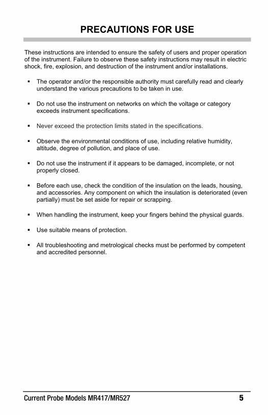
These instructions are intended to ensure the safety of users and proper operation of the instrument. Failure to observe these safety instructions may result in electric shock, fire, explosion, and destruction of the instrument and/or installations.
The operator and/or the responsible authority must carefully read and clearlyunderstand the various precautions to be taken in use.
Do not use the instrument on networks on which the voltage or categoryexceeds instrument specifications.
Never exceed the protection limits stated in the specifications.
Observe the environmental conditions of use, including relative humidity,altitude, degree of pollution, and place of use.
Do not use the instrument if it appears to be damaged, incomplete, or notproperly closed.
Before each use, check the condition of the insulation on the leads, housing,and accessories. Any component on which the insulation is deteriorated (evenpartially) must be set aside for repair or scrapping.
When handling the instrument, keep your fingers behind the physical guards.
Use suitable means of protection.
All troubleshooting and metrological checks must be performed by competentand accredited personnel.
6 Current Probe Models MR417/MR527
RECEIVING YOUR SHIPMENT
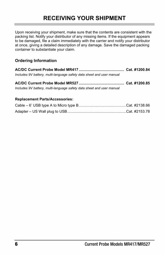
Upon receiving your shipment, make sure that the contents are consistent with the packing list. Notify your distributor of any missing items. If the equipment appears to be damaged, file a claim immediately with the carrier and notify your distributor at once, giving a detailed description of any damage. Save the damaged packing container to substantiate your claim.
Ordering Information
AC/DC Current Probe Model MR417 ........................................... Cat. #1200.84 Includes 9V battery, multi-language safety data sheet and user manual
AC/DC Current Probe Model MR527 ........................................... Cat. #1200.85 Includes 9V battery, multi-language safety data sheet and user manual
Replacement Parts/Accessories: Cable – 6’ USB type A to Micro type B ............................................. Cat. #2138.66 Adapter – US Wall plug to USB ........................................................ Cat. #2153.78

Current Probe Models MR417/MR527 7
1 DESCRIPTION
The Models MR417 and MR527 are clamp-on current probes that measure DC currents up to 1400A, AC currents up to 1000ARMS (1400A peak), and combined AC+DC currents without opening the circuit in which the currents flow. They indicate the shape and amplitude of the current measured in the form of a voltage.
These instruments can be used with oscilloscopes. They can be powered by a battery or with 5VDC via the optional micro‑USB cable.
The MR417 and MR527 include the following features:
overage indicator
power supply indicator
zero adjustment
Auto Standby feature
two ranges (sensitivity 1 and 10mV/A)
micro‑USB connector to connect an external power supply

8 Current Probe Models MR417/MR527
1.1 Interface 1.1.1 MR417
Figure 1 (MR417)
Item Functions 1 Fixed (non-mobile) jaw 2 Arrow indicating current flow direction 3 Male BNC connector 4 DC Zero button
5 OL (overload) and ON indicators. ON is green when Auto Standby is enabled, yellow when it disabled.
6 3-position slide switch7 USB port 8 Trigger 9 Hand guard
10 Mobile jaw
1
2
3
4
5
7
8
9
10
6

Current Probe Models MR417/MR527 9
1.1.2 MR527
Figure 2 (MR527)
Item Functions 1 Fixed (non-mobile) jaw 2 Arrow indicating current flow direction 3 Male BNC connector 4 DC Zero button
5 OL (overload) and ON indicators. ON is green when Auto Standby is enabled, yellow when it disabled.
6 3-position slide switch7 USB port 8 Trigger 9 Hand guard
10 Mobile jaw
1
2
3
4
5
7
8
9
10
6

10 Current Probe Models MR417/MR527
2 OPERATION
2.1 Battery Installation Before changing batteries: set the switch to OFF and remove the clamp from the circuit under measurement.
1. Using a screwdriver, remove the battery compartment cover (1) from theback of the housing (see Figure 3).
2. Connect the battery to the snap-on connector (2), observing polarity.3. Place the battery into the battery compartment (3).4. Replace the battery compartment cover and screw it onto the housing.
Figure 3
2.2 External Power (Optional) For long‑term measurements, you can connect the clamp to external power via any micro‑USB adapter that delivers 100mA or more. If external power is disconnected, the clamp automatically switches to battery operation.
The insulation between the type B micro‑USB connector and the measurement output is 600V CAT III. This enables you to safely connect the clamp to measuring instruments with uninsulated inputs. The type B micro‑USB connector must not be in contact with conductors or uninsulated parts at dangerous voltage.
When operating on external power, the Auto Standby feature is disabled. The color of the ON indicator shows whether automatic standby is enabled (green) or disabled (yellow).
1
2
3
Current Probe Models MR417/MR527 11
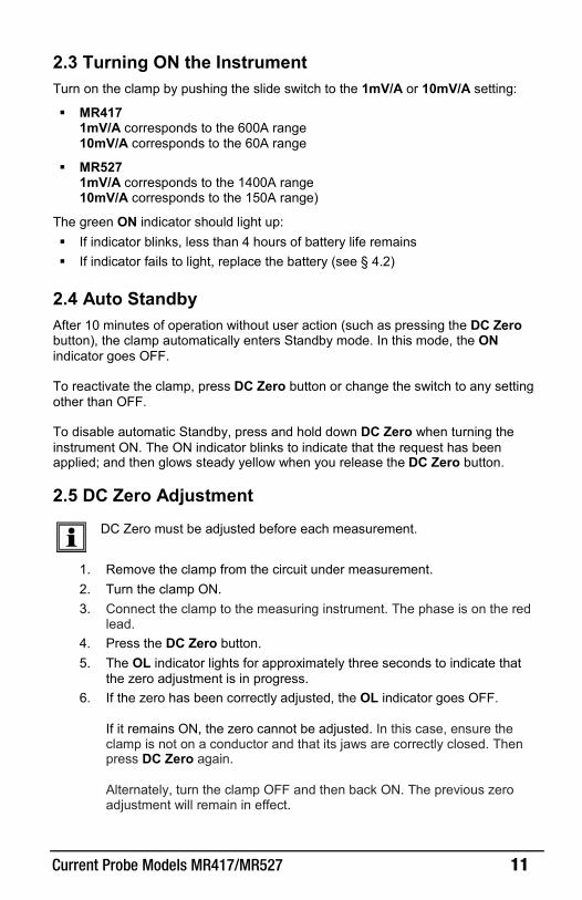
2.3 Turning ON the Instrument Turn on the clamp by pushing the slide switch to the 1mV/A or 10mV/A setting:
MR4171mV/A corresponds to the 600A range10mV/A corresponds to the 60A range
MR5271mV/A corresponds to the 1400A range10mV/A corresponds to the 150A range)
The green ON indicator should light up: If indicator blinks, less than 4 hours of battery life remains If indicator fails to light, replace the battery (see § 4.2)
2.4 Auto Standby After 10 minutes of operation without user action (such as pressing the DC Zero button), the clamp automatically enters Standby mode. In this mode, the ON indicator goes OFF.
To reactivate the clamp, press DC Zero button or change the switch to any setting other than OFF.
To disable automatic Standby, press and hold down DC Zero when turning the instrument ON. The ON indicator blinks to indicate that the request has been applied; and then glows steady yellow when you release the DC Zero button.
2.5 DC Zero Adjustment
DC Zero must be adjusted before each measurement.
1. Remove the clamp from the circuit under measurement.2. Turn the clamp ON.3. Connect the clamp to the measuring instrument. The phase is on the red
lead.4. Press the DC Zero button.5. The OL indicator lights for approximately three seconds to indicate that
the zero adjustment is in progress.6. If the zero has been correctly adjusted, the OL indicator goes OFF.
If it remains ON, the zero cannot be adjusted. In this case, ensure theclamp is not on a conductor and that its jaws are correctly closed. Thenpress DC Zero again.
Alternately, turn the clamp OFF and then back ON. The previous zeroadjustment will remain in effect.

12 Current Probe Models MR417/MR527
2.6 Measurements
2.6.1 Making a Measurement After adjusting DC Zero:
1. Press the clamp trigger to open the jaws.2. Clamp the jaws around the conductor to be measured. Use the centering
marks on the jaws to position the clamp around the conductor. If themeasurement is to be used in a power calculation, ensure the arrow onthe clamp jaws (see Figures 1 and 2) points in the direction of the currentflow: source load.
3. Release the trigger, ensuring the jaws are completely and correctlyclosed.
4. Observe the measurement displayed on the measuring instrument.5. If the OL indicator lights, the current is too high to be measured. If the
sliding switch is set to the 10mV/A range, change the setting to 1mV/A.
Figure 4 (MR527 shown)
2.6.2 Converting to Current The MR417 and MR527 both provide two measurement ranges. The MR417 measures current up to 600A with 1mV of output corresponding to 1A, and current up to 60A with 10mV corresponding to 1A. The MR527 measures current up to 1400A with 1mV corresponding to 1A, and current up to 150A with 10mV corresponding to 1A.
To convert the clamp output to current, divide the voltage reading on the connected measuring by the V/A coefficient. For example, in the MR527’s 1400A range a reading of 100mV corresponds to a current of 100A.
Current Probe Models MR417/MR527 13
3 SPECIFICATIONS
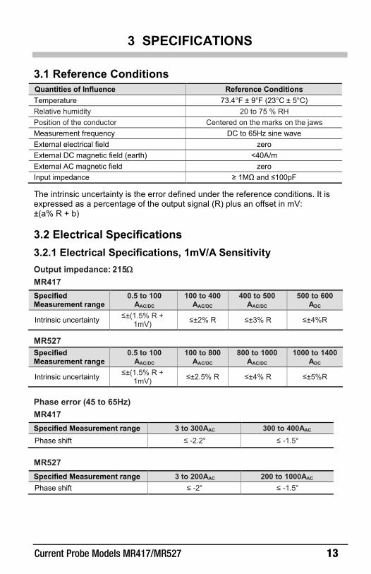
3.1 Reference Conditions Quantities of Influence Reference Conditions Temperature 73.4°F ± 9°F (23°C ± 5°C) Relative humidity 20 to 75 % RH Position of the conductor Centered on the marks on the jaws Measurement frequency DC to 65Hz sine wave External electrical field zero External DC magnetic field (earth) <40A/m External AC magnetic field zero Input impedance ≥ 1MΩ and ≤100pF
The intrinsic uncertainty is the error defined under the reference conditions. It is expressed as a percentage of the output signal (R) plus an offset in mV: ±(a% R + b)
3.2 Electrical Specifications 3.2.1 Electrical Specifications, 1mV/A Sensitivity Output impedance: 215Ω MR417
Specified Measurement range
0.5 to 100 AAC/DC
100 to 400 AAC/DC
400 to 500 AAC/DC
500 to 600 ADC
Intrinsic uncertainty ≤±(1.5% R + 1mV) ≤±2% R ≤±3% R ≤±4%R
MR527 Specified Measurement range
0.5 to 100 AAC/DC
100 to 800 AAC/DC
800 to 1000 AAC/DC
1000 to 1400 ADC
Intrinsic uncertainty ≤±(1.5% R + 1mV) ≤±2.5% R ≤±4% R ≤±5%R
Phase error (45 to 65Hz) MR417
Specified Measurement range 3 to 300AAC 300 to 400AAC Phase shift ≤ -2.2° ≤ -1.5°
MR527
Specified Measurement range 3 to 200AAC 200 to 1000AAC Phase shift ≤ -2° ≤ -1.5°
14 Current Probe Models MR417/MR527
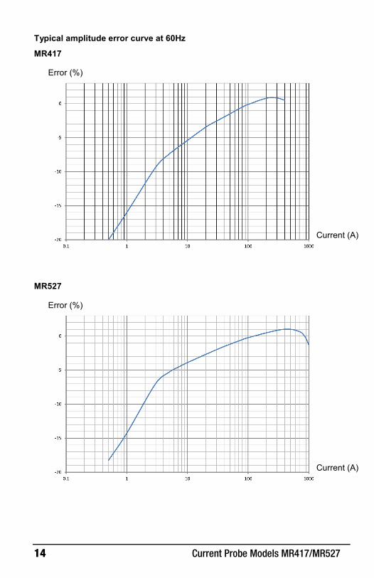
Typical amplitude error curve at 60Hz
MR417
MR527
Error (%)
Current (A)
Error (%)
Current (A)

Current Probe Models MR417/MR527 15
Typical amplitude error curve in DC
MR417
MR527
Error (%)
Current (A)
Error (%)
Current (A)
16 Current Probe Models MR417/MR527
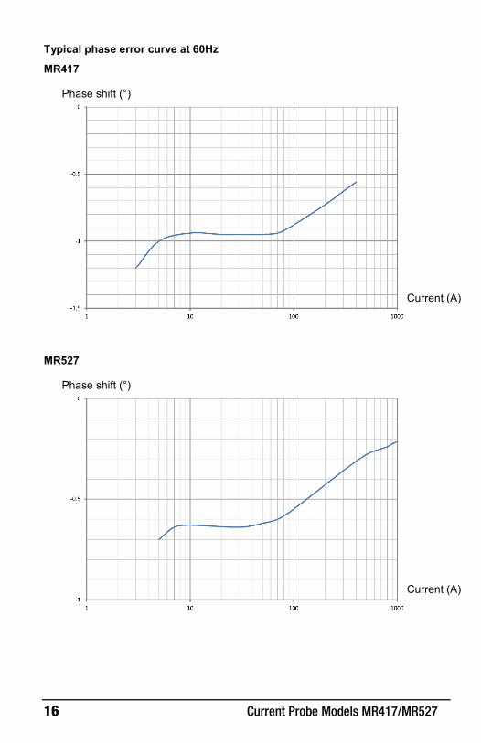
Typical phase error curve at 60Hz
MR417
MR527
Phase shift (°)
Current (A)
Phase shift (°)
Current (A)

Current Probe Models MR417/MR527 17
3.2.2 Frequency Specifications, 1mV/A Sensitivity
Bandwidth -3dB: DC to 30kHz
Frequency 50Hz 400Hz 1kHz 10kHz
Insertion impedance <0.01mΩ
MR417: 0.01mΩ MR527: 0.05mΩ
MR417: 0.12mΩ MR527: 0.14mΩ
MR417: 2.8mΩ MR527: 3.4mΩ
Typical amplitude error versus frequency curve at 100A
MR417
MR527
Error (%)
Frequency (Hz)
Error (%)
Frequency (Hz)
18 Current Probe Models MR417/MR527
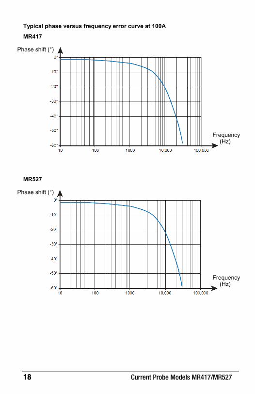
Typical phase versus frequency error curve at 100A
MR417
MR527
Phase shift (°)
Frequency (Hz)
Phase shift (°)
Frequency (Hz)
Current Probe Models MR417/MR527 19
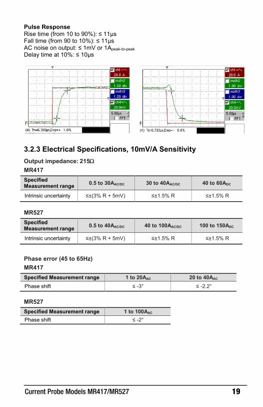
Pulse Response Rise time (from 10 to 90%): ≤ 11μs Fall time (from 90 to 10%): ≤ 11μs AC noise on output: ≤ 1mV or 1Apeak-to-peak Delay time at 10%: ≤ 10μs
3.2.3 Electrical Specifications, 10mV/A Sensitivity Output impedance: 215Ω MR417
Specified Measurement range 0.5 to 30AAC/DC 30 to 40AAC/DC 40 to 60ADC
Intrinsic uncertainty ≤±(3% R + 5mV) ≤±1.5% R ≤±1.5% R
MR527
Specified Measurement range 0.5 to 40AAC/DC 40 to 100AAC/DC 100 to 150ADC
Intrinsic uncertainty ≤±(3% R + 5mV) ≤±1.5% R ≤±1.5% R
Phase error (45 to 65Hz) MR417
Specified Measurement range 1 to 20AAC 20 to 40AAC Phase shift ≤ -3° ≤ -2.2°
MR527
Specified Measurement range 1 to 100AAC Phase shift ≤ -2°

20 Current Probe Models MR417/MR527
Typical amplitude error vs current curve at 60Hz
MR417
MR527
Error (%)
Current (A)
Error (%)
Current (A)

Current Probe Models MR417/MR527 21
Typical amplitude error vs current curve in DC
MR417
MR527
Error (%)
Current (A)
Error (%)
Current (A)
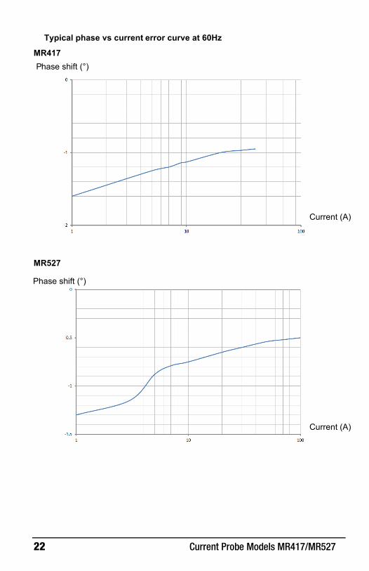
22 Current Probe Models MR417/MR527
MR527
Typical phase vs current error curve at 60Hz
MR417 P hase shift (°)
Current (A)
Phase shift (°)
Current (A)

Current Probe Models MR417/MR527 23
3.2.4 Frequency Specifications, 10mV/A Sensitivity Bandwidth -3dB: DC to 30kHz Frequency 50Hz 400Hz 1kHz 10kHz
Insertion impedance <0.01mΩ
MR417: 0.01mΩ MR527: 0.05mΩ
MR417: 0.12mΩ MR527: 0.14mΩ
MR417: 2.8mΩ MR527: 3.4mΩ
Typical amplitude error versus frequency curve at 100A
MR417
MR527
Error (%)
Frequency (Hz)
Error (%)
Frequency (Hz)

24 Current Probe Models MR417/MR527
Typical phase versus frequency error curve at 100A
MR417
MR527
Phase shift (°)
Frequency (Hz)
Phase shift (°)
Frequency (Hz)

Current Probe Models MR417/MR527 25
Pulse Response Rise time (from 10 to 90%): ≤ 11μs Fall time (from 90 to 10%): ≤ 11μs AC noise on output: ≤ 3mV or 0.3Apeak-to-peak Delay time at 10%: ≤ 10μs
Square wave response curves
3.3 Operating Limits In DC: 3000A permanent In AC: 1000A permanent up to 1kHz
from 1kHz, IMAX = 1000/f (kHz) Conductor temperature: ≤ 194°F (90°C), 230°F (110°C) peak Temperature of the jaws: ≤ 176°F (80°C)
Curve of derating versus frequency
Current (A)
Frequency (kHz)

26 Current Probe Models MR417/MR527
3.4 Variations in the Range of Use
Quantity of influence Range of influence Error in % of reading Typical Maximum
Temperature 14 to 131°F (‑10 to + 55°C) 0.3%
Relative humidity 10 to 85% RH 0.5%
Frequency 10 to 400Hz
400Hz to 7kHz 7 to 30kHz
1% 3.5%
see curves Position of the conductor 0.79” (20mm) in diameter 0.5%
Adjacent conductor carrying a 50Hz AC current
Conductor 0.91” (23mm) from the clamp 10mA/A
External 400A/m field at 50Hz Cable centered 1.3A
Common mode rejection 600V between jacket and secondary
65dB A/V at 50Hz
Remanence
MR417: 50ADC: 1.2A 100ADC: 2.3A 200ADC: 3.4A 400ADC: 4.8A 600ADC: 5.5A 800ADC: 5.8A
MR527: 100ADC: 2.8A 200ADC: 3.5A 400ADC: 5A 800ADC: 5.3A 1200ADC: 5.7A 1400ADC: 5.8A
3.5 Power Supply The instrument is powered by a 9V battery (type 6LR61, 6LF22, or NEDA 1604). The average battery life is 50 hours with an alkaline battery.
The instrument can also be powered by an external supply (5VDC, 100mA) via the type B micro‑USB connector.

Current Probe Models MR417/MR527 27
3.6 Environmental Conditions The instrument must be used in the following environmental conditions.
1 = Range of reference
2 = Operating range
3 = Storage range
Indoor use
Degree of pollution: 2
Altitude: < 6500’ (2000m)
Transport altitude: ≤ 40,000’ (12,000m)
%RH
°C

28 Current Probe Models MR417/MR527
3.7 Mechanical Specifications
MR417 Dimensions (L x W x H): 8.8” x 3.8” x 1.7” (224 x 97 x 44mm)
Weight: approximately 15.5oz (440g)
Cable: 6.6’ (2m)
Clamping diameter: 1.2” (30mm) in diameter, two cables 0.94” (24mm) in diameter, one 1.97 x 0.39” (50 x 10mm) bar or two 1.24 x 0.30” (31.5 x 10mm), three 0.98 x 0.31” (25 x 8mm) bars, two 0.98 x 0.2” (25 x 5mm) bars
Figure 5

Current Probe Models MR417/MR527 29
MR527
Dimensions (L x W x H): 9.3” x 3.8” x 1.7” (237 x 97 x 44mm)
Weight: approximately 18.3oz (520g)
Cable: 6.6’ (2m)
Clamping diameter: 1.5” (39mm) in diameter, two cables 1” (25.4mm) in diameter, one 1.97 x 0.49” (50 x 12.5mm) bar or two 1.96 x 0.2” (50 x 5mm) bars or 1.24 x 0.30” (31.5 x 10mm), three 0.98 x 0.31” (25 x 8mm) bars, two 0.98 x 0.2” (25 x 5mm) bars
Figure 6

30 Current Probe Models MR417/MR527
3.7.1 Housing Protection Protection index: IP 40 per IEC 60529 IK 06 per IEC 62262
Drop test per IEC 61010-2-032.
3.8 International Standards The instrument is compliant with IEC 61010-2-032, 300V in CAT IV or 600V in CAT III. Double or reinforced insulation Type of current sensor per IEC 61010-2-032: type A
3.9 Electromagnetic Compatibility The device is in conformity with standard IEC 61326-1.

Current Probe Models MR417/MR527 31
4 MAINTENANCE
Except for the battery, the instrument contains no parts that can be replaced by personnel who have not been specially trained and accredited. Any unauthorized repair or replacement of a part by an "equivalent" may gravely impair safety.
4.1 Cleaning Disconnect the instrument completely.
Use a soft cloth, dampened with soapy water.
Rinse with a damp cloth and dry rapidly with a dry cloth or forced air.
Do not use alcohol, solvents, or hydrocarbons.
Keep the clamp jaws as clean as possible.
4.2 Battery Replacement The battery must be replaced if the ON indicator remains unlit when the instrument is turned ON.
1. Disconnect the instrument completely and set the switch to OFF.
2. Remove the battery compartment cover from the instrument casing (see § 2.1).
3. Remove the old battery.
4. Insert the replacement battery into the snap-in battery connector, and place itinto the battery compartment.
5. Replace the battery compartment cover.
Spent batteries must not be treated as ordinary household waste. Take them to the appropriate collection point for recycling.
32 Current Probe Models MR417/MR527
REPAIR AND CALIBRATION
To ensure that your instrument meets factory specifications, we recommend that it be submitted to our factory Service Center at one-year intervals for recalibration, or as required by other standards or internal procedures.
For instrument repair and calibration: You must contact our Service Center for a Customer Service Authorization number (CSA#). This will ensure that when your instrument arrives, it will be tracked and processed promptly. Please write the CSA# on the outside of the shipping container. If the instrument is returned for calibration, we need to know if you want a standard calibration, or a calibration traceable to N.I.S.T. (includes calibration certificate plus recorded calibration data).
(Or contact your authorized distributor) Costs for repair, standard calibration, and calibration traceable to N.I.S.T. are available. NOTE: All customers must obtain a CSA# before returning any instrument.
TECHNICAL AND SALES ASSISTANCE
If you are experiencing any technical problems, or require any assistance with the proper operation or application of your instrument, please call, mail, fax or e-mail our technical support hotline:
NOTE: Do not ship instruments to our Foxborough, MA address.

Current Probe Models MR417/MR527 33
LIMITED WARRANTY
The instrument is warranted to the owner for a period of two years from the date of original purchase against defects in manufacture. This limited warranty is given by AEMC® Instruments, not by the distributor from whom it was purchased. This warranty is void if the unit has been tampered with, abused or if the defect is related to service not performed by AEMC® Instruments.
Please print the online Warranty Coverage Information for your records. If a malfunction occurs within the warranty period, you may return the instrument to us for repair, provided we have your warranty registration information on file or a proof of purchase. AEMC® Instruments will, at its option, repair or replace the faulty material.
Warranty Repairs What you must do to return an Instrument for Warranty Repair: First, request a Customer Service Authorization Number (CSA#) by phone or by fax from our Service Department (see address below), then return the instrument along with the signed CSA Form. Please write the CSA# on the outside of the shipping container. Return the instrument, postage or shipment pre-paid to:
Caution: To protect yourself against in-transit loss, we recommend you insure your returned material.
NOTE: All customers must obtain a CSA# before returning any instrument.

34 Current Probe Models MR417/MR527
NOTES
Current Probe Models MR417/MR527 35
NOTES

09/19
99-MAN 100522 v1
Test Equipment Depot - 800.517.8431 - 99 Washington Street Melrose, MA 02176
TestEquipmentDepot.com