Embed Size (px)
Citation preview

ACCON-NetLink-WLAN User Manual
The Best Solutions for PLC

ACCON-NetLink-WLAN 1
This manual is for project developers, users and assemblers who utilize the ACCON-NetLink-WLAN.
It shows the user the handling of the ACCON-NetLink-WLAN and explains signaling functions. All necessary data for assembling should be provided to the assembler. © 1995 - 2010
DELTALOGIC Automatisierungstechnik GmbH Stuttgarter Strasse 3 73525 Schwaebisch Gmuend Germany
Phone sale: +49-(0)7171-916-120 Phone support: +49-(0)7171-916-112
Fax sale: +49-(0)7171-916-220 Fax support: +49-(0)7171-916-212
E-Mail sale: [email protected] E-Mail support: [email protected]
www.deltalogic.de
All rights reserved. No part of this work is allowed to be copied, reproduced, conferred, processed and stored into electronic media or translated into any other language without a written permission of the author.
S7-200®, S7-300®, S7-400®, HMI®, STEP® and SIMATIC® are registered trademarks of Siemens AG, ACCON® and DELTALOGIC® are registered trademarks of DELTALOGIC Automatisierungstechnik GmbH.
Note:
We have checked the content of this manual for conformity with the hardware and software described. Nevertheless, because deviations cannot be ruled out, we cannot accept any liability for complete conformity. The data in this manual have been checked regularly and any necessary corrections will be included in subsequent editions. We always welcome suggestions for improvement.
Last update 2010-03-01. All technical changes reserved.

ACCON-NetLink-WLAN 2
TABLE OF CONTENTS
1 TECHNICAL DESCRIPTION................................................3
2 SCOPE OF DELIVERY..........................................................5
3 DEVICE DESCRIPTION........................................................6
4 REQUIREMENTS FOR OPERATING.................................9
5 COMMISSIONING.............................................................10
6 TCP/IP PARAMETRIZATION ..........................................20
7 BUS SETTINGS...................................................................24
8 COMMUNICATION VIA RFC1006 (S7-TCP/IP)........32
9 THE WEB INTERFACE ......................................................39
10 REMOTE MAINTENANCE WITH THE ACCON-NETLINK-WLAN.................................................................52
11 TROUBLE SHOOTING ......................................................54
12 FREQUENTLY ASKED QUESTIONS..............................56
13 TECHNICAL DATA.............................................................59
14 APPENDIX ...........................................................................63

ACCON-NetLink-WLAN 3
1 TECHNICAL DESCRIPTION
The ACCON-NetLink-WLAN is a high-tech communications and programming adapter between a PC and a S7 controller. This convincing all-round device can be connected to the PLC via MPI, PROFIBUS and PPI. The ACCON-NetLink-WLAN detects the current bus settings, independently. The connection cable of the ACCON-NetLink-WLAN to the Bus (MPI, PROFIBUS or PPI) is an active connection, so there are no bus interferences due to a spur line.
Figure 1: Build-up
The ACCON-NetLink-WLAN's communication to the PC is carried out via TCP/IP. Alternative by accessing by WLAN the ACCON-NetLink-WLAN has also a RJ45 Ethernet Interface. The configuration of the ACCON-NetLink-WLAN can be created and changed via its integrated web site. For security reasons the access to the web site is protected by a password.
The ACCON-NetLink-WLAN supports the S7 communication via RFC1006 (ISO on TCP). Thus TCP/IP communication processors (e. g. CP343-1) can be replaced by this adapter. But projected connections are not supported. Furthermore the ACCON-NetLink-WLAN supports the parametrization of DP-Slaves via DP-V1 (Class 2). A driver for SIMATIC applications (ACCON-S7-NET) is included in delivery. The ACCON-NetLink-WLAN is fed via the bus connection. Alternatively, the device can be externally supplied via 24 VDC.

ACCON-NetLink-WLAN 4
The ACCON-NetLink-WLAN can be connected to the PC via a hub or switch. The supplied patch cable (straight) is used to connect the ACCON-NetLink-WLAN via a switch.
Features:
• WLAN-Interface
• Optional RJ45 Ethernet-Interface
• Automatic bus profile detection
• Full PROFIBUS speed up to 12 MBit/s
• Extended diagnostics
• Support of MPI, PROFIBUS and PPI
• Supports DHCP
• Support of Slave programming via DP-V1 (Class 2)
• Supports all established SIMATIC Engineering Tools
• Supports ISO on TCP (RFC 1006)
• Active connection cable, so there are no bus interferences due to a spur line.
• Voltage feed from the PLC or controller
• External 24-V power supply possible
• Plug with PG bushing
• Galvanically separated
• Applicable up to 60 °C

ACCON-NetLink-WLAN 5
2 SCOPE OF DELIVERY
• ACCON-NetLink-WLAN
• short, screw-on WLAN-antenna with RP-SMA (female)
• Patch cable (straight, 3 meters)
• DELTALOGIC Automatisierungstechnik-CD including ACCON-S7-NET-Driver
• User manual
Suitable accessories can be found on www.deltalogic.de.

ACCON-NetLink-WLAN 6
3 DEVICE DESCRIPTION
Figure 2: ACCON-NetLink-WLAN
1. WLAN antenna connector; RP-SMA with pin
2. RJ45 bushing to connect the device to the Ethernet
3. WLAN Status LEDs
4. Status LEDs
5. Bus plug with PG bushing, switchable terminator and 1,2 meter connection line. The connection line is decoupled from the bus by an active bus plug. So there is no spur line which could interfere with the bus.
6. Power supply bushing for 24 VDC. Please keep the polarity in mind.
7. Patch cable (straight, 3 meters)
8. WLAN antenna (RP-SMA)
1.
2. 4
.
6.
5.
7.
3
8.

ACCON-NetLink-WLAN 7
Start of the ACCON-NetLink-WLAN
When the starting is complete only the Power LED lights permanently green. Now starting is finished and the device is ready to operate. If RFC1006 is activated, the LEDs Power and Active will light permanently green after the starting procedure.
LED display
Power LED Online LED Connected
LED
Ready to operate GREEN
Trying to log in on the device at the bus
GREEN GREEN
BLINKING
Device is logged in on the bus
GREEN GREEN
Active connection to a controller
GREEN GREEN GREEN
Data exchange with a controller (Data)
GREEN GREEN GREN
BLINKING
Table 1: Status LEDs
Update LED Param. LED Data LED
Transmitting firmware update
GREEN BLINKING
RED BLINKING
RED BLINKING
Storing firmware update
GREEN RED RED
Table 2: Status LEDs Firmware Update

ACCON-NetLink-WLAN 8
Link LED GRÜN Active LED GELB
No Ethernet connection
OFF OFF
Ethernet activity ON BLINKING
Table 3: Status LEDs Ethernet
Diag LED YELLOW
No Error (WLAN) OFF
Error ON
configuration read/write
BLINKING
Tabelle 4: WLAN-LED Diag
Active LED GREEN
No WLAN connection OFF
Device is connected by WLAN
ON
Trying to connect by WLAN
BLINKING
Tabelle 5: WLAN-LED Active

ACCON-NetLink-WLAN 9
4 REQUIREMENTS FOR OPERATING
Hardware
Siemens S7-200-, S7-300 and S7-400 automation devices or compatible to S7. The utilized PCs must have a working network connection via TCP/IP. Also the network configuration must be known. Usual WLAN or network cards are suitable.
Software
To use the ACCON-S7-NET drivers you need a PC including Windows 2000 or Windows XP. On this PC the SIMATIC Device Drivers (PG/PC-Interface) have to be installed. The SIMATIC Device Drivers will be installed with e. g. STEP 7, STEP 7 lite or STEP 7-Micro/Win. By installing ACCON-S7-NET more interfaces will be added to the PG/PC-Interface.
Assembly
Installation and assembly have to be carried out according to VDE 0100 / IEC 364. As the ACCON-NetLink-WLAN is a IP30 module it has to be built into a switch cabinet.
For secure operating please keep the maximum ambient temperature of 60 °C in mind.
Module assembly
To assemble the device a top hat rail holder is necessary. Available as accessory.

ACCON-NetLink-WLAN 10
5 COMMISSIONING
The ACCON-NetLink-WLAN is shipped with the IP address 192.168.4.49.
Connection to the automation device
Connect the 9-pin SUB-D plug to the MPI or PROFIBUS interface of your S7 controller.
Connection to the PC via RJ45 Ethernet-Interface
Put one end of the patch cable into the Ethernet bushing of your ACCON-NetLink-PRO and the other end into a hub or switch which is connected to your PC's network card.
You can also directly connect the ACCON-NetLink-PRO to your PC's network card without a switch. Instead of the supplied patch cable you have to use a cross-over cable (not included in delivery).
Connection to the PC via WLAN (Ad-Hoc Modus)
Figure 3: Build-up

ACCON-NetLink-WLAN 11
The ad hoc mode describes an operating mode in which the WLAN components communicate with each other directly. There-fore, no central coordination point (access point) is involved in the communication. The data transfer is realized directly by and between the WLAN components. That is why this operating mode is also called “peer to peer mode”.
In order to connect ACCON-NetLink-WLAN directly with a PG/PC the following aspects have to be regarded:
· The WLAN function needs to be activated in ACCON-NetLink-WLAN
· The ad hoc mode needs to be selected in ACCON-NetLink-WLAN
· ACCON-NetLink-WLAN needs to be defined with a station name
· The channel on which ACCON-NetLink-WLAN is supposed to send needs to be selected
· The desired encoding settings need to be made (in the ad hoc mode you can only use the relatively insecure WEP encoding standard)
· The party that starts the communication has to be able to understand one of the WLAN standards 802.11b or 802.11g furthermore the ACCON-NetLink-WLAN has to have a fixed IP address, since the adapter does not serve as a DHCP Server.
· Connection establishment PC to ACCON-NetLink-WLAN in the unencrypted ad hoc mode
At this time it is assumed that ACCON-NetLink-WLAN already disposes of a station name, that it is reachable via WLAN in the ad hoc mode and that the WLAN connection is configurable via the Windows WLAN assistant.
1. Step: The WLAN adapter has recognized the wireless networks in operating distance.
2. Step: This screen appears when you open the ‘Wireless Net-works’ manager by clicking the WLAN symbol.

ACCON-NetLink-WLAN 12
3. Step: Now select the ACCON-NetLink-WLAN, here ‘NL Andy’, that you wish to connect to.
4. Step: In order to establish the connection it is necessary to click the ‘Connect’ and the ‘Connect anyway’ buttons. The ‘Connect anyway’ button will only appear if no en-coding is set in ACCON-NetLink-WLAN.
5. Step: The connection to ACCON-NetLink-WLAN is now successfully established, and it can be implemented e.g. via the PG/PC interface parameterization.

ACCON-NetLink-WLAN 13
Connection establishment PC to ACCON-NetLink-WLAN in the encoded ad hoc mode
At this time it is assumed that ACCON-NetLink-WLAN is configured similar to the configuration shown on the following screen and that it is accessible via WLAN. Keep in mind to enter 26 charac-ters in the box for the encoding key when using WEP 128 bit. The characters are only displayed if you tick the check box ‘Show key’. Otherwise the ‘Key’ is hidden. Furthermore the WLAN connection in this example has to be configurable via the Windows WLAN assistant or via another producer.
1. Step: The WLAN adapter has recognized the wireless networks in operating distance.
2. Step: Open the ‘Wireless Net-works’ manager by clicking the WLAN symbol.
3. Schritt: Now select the ACCON-NetLink-WLAN, here ‘NL Andy’, that you wish to connect to.
4. Step: Now enter the valid key for the respective ACCON-NetLink-WLAN and confirm by clicking the ‘Connect’ button. Windows does not display the key, either, but keeps the characters hidden.

ACCON-NetLink-WLAN 14
5. Step: The manager now indicates to obtain a network address. That is not entirely correct, since ACCON-NetLink-WLAN can-not allocate IP addresses. Therefore, the wireless net-work connection needs to be given a fixed IP before-hand.
6. Step: Afterwards the following screen is shown. The connec-tion is now properly established, and ACCON-NetLink-WLAN can now be used e.g. as programming adapter.

ACCON-NetLink-WLAN 15
ACCON-NetLink-WLAN in the infrastructure mode (AP)
When using the infrastructure mode the communication of two WLAN components is handled by a mediation unit, an access point (AP). The AP functions as central coordination point of the communication. The infrastructure mode that has to consist of at least one WLAN end device and an AP is also called BSS.
Comparable to a mobile network the AP establishes a radio cell that is spatially restricted. WLAN end devices such as NETLink need to log on to this radio cell and authenticate to it. The au-thentication does only occur if the access data to the radio cell is stored in ACCON-NetLink-WLAN.
In order to log on ACCON-NetLink-WLAN to an infrastructure net the following aspects have to be regarded:
· The WLAN function needs to be activated in ACCON-NetLink-WLAN
· The infrastructure mode needs to be selected in ACCON-NetLink-

ACCON-NetLink-WLAN 16
WLAN
· The SSID of the access point needs to be stored in ACCON-NetLink-WLAN
· The encoding settings of ACCON-NetLink-WLAN need to correspond with those of the access point
ACCON-NetLink-WLAN 17
Installation software
After inserting the DELTALOGIC Automatisierungstechnik-CD please start the data file SetupAcconS7Net.exe for the ACCON-S7-NET driver (<CD-drive>\ACCON-NetLink\S7-Treiber).
For an installation under Windows 2000 and Windows XP you have to be logged in as administrator.
Set PG/PC-Interface
1. Open the SIMATIC PG/PC interface
The following points have to be in the dialog «Set PG/PC Interface«:
- ACCON-S7-NET NLPro(MPI)
- ACCON-S7-NET NLPro(PPI)
- ACCON-S7-NET NLPro(PROFIBUS)
Figure 4: Set PG/PC Interface

ACCON-NetLink-WLAN 18
If not then
- click on the button »Select…« to add/remove interfaces. Now you can see the window »Install/Remove Interfaces«.
- choose the module »ACCON-S7-NET NLPro and install the adapter.
2. Click on the button »Properties«.
Figure 5: A new created station
3. Click on »New« to create a station for the ACCON-NetLink-WLAN. By selecting a station it is set which ACCON-NetLink-WLAN is assigned to the PG/PC Interface. But these stations will not be stored in the ACCON-NetLink-WLAN.
Figure 6: Set a station

ACCON-NetLink-WLAN 19
4. Click on »Search ACCON-NetLink-WLAN…« in the »Station« dialog. The following window appears:
Figure 7: List of all connected ACCON-NetLink-WLAN devices
6. Mark the ACCON-NetLink-WLAN and click on »Close + Get«. If the list is empty please read the chapter »Trouble shooting«.
7. The window »Station« appears again. Click on »OK«. The driver settings are completed now.
8. Close the window »Properties – ACCON-S7-NET NLPro(MPI)« by a click on »OK«.
9. Close the window »Set PG/PC-Interface« by a click on »OK«.
10. When an access path is changed in this settings a warning appears. Confirm with »OK« when you want to accept the changes.
The ACCON-NetLink-WLAN is shipped with the IP address 192.168.4.49. The ACCON-NetLink-WLAN's IP address must fit into your network. For this the first three places of the IP address of the PC and the ACCON-NetLink-WLAN have to be equal, e. g. PC: IP address 192.168.4.10, ACCON-NetLink-WLAN IP address 192.168.4.49 (only valid if subnet mask 255.255.255.0 is used). For more information please go to chapter 7 »TCP/IP Parametrization«.
The ACCON-NetLink-WLAN can be parametrized via a web interface, too. To do this open your web browser and enter the URL »http://192.168.4.49« as long as you did not change the default address.

ACCON-NetLink-WLAN 20
6 TCP/IP PARAMETRIZATION
There are two ways:
• Parametrization via »Set PG/PC Interface«
• Parametrization via the web interface of the ACCON-NetLink-WLAN (look for chapter 9)
The ACCON-NetLink-WLAN will be shipped with the IP address 192.168.4.49.
Setting TCP/IP parameters
To change the TCP/IP parameters select the desired station and click on »Edit«. The following window appears.
Figure 8: Set station
Via »Parametrize ACCON-NetLink-WLAN...« you get to the input mask with the ACCON-NetLink-WLAN's parameters.

ACCON-NetLink-WLAN 21
Figure 9: Settings of the ACCON-NetLink-WLAN
Static TCP/IP configuration
If the ACCON-NetLink-WLAN is used in a network without a DHCP server or if the ACCON-NetLink-WLAN should always work with the same IP address despite an existing DHCP server, you have to enter the desired IP address into the input mask for »Static entries«. In this case you must not set the function »Get IP address automatically (DHCP)«.
The ACCON-NetLink-WLAN's IP address must fit into your network. For this the first three places of the IP address of the PC and the ACCON-NetLink-WLAN have to be equal, e. g. PC: IP address 192.168.4.10, ACCON-NetLink-WLAN IP address 192.168.4.49 (only valid if subnet mask 255.255.255.0 is used).
Use of DHCP (Dynamic Host Configuration Protocol)
The problem with DHCP is, that after every switch-on the parametrized ACCON-NetLink-WLAN can get another IP address. The system administrator responsible for the DHCP server can prevent it. The ACCON-NetLink-WLAN's MAC address must have a permanent IP address at the DHCP server.
If the ACCON-NetLink-WLAN should get the IP address via DHCP automatically, you have to set the function »Get IP address automatically (DHCP)«.

ACCON-NetLink-WLAN 22
Additionally, the field »DHCP Timeout in s« will be activated. If the ACCON-NetLink-WLAN does not get any parameters from a DHCP server within the time set, the device uses the static parameters to assure that the ACCON-NetLink-WLAN is available in the network and if necessary configurable.
Values smaller than 30 seconds will be replaced by the default value (30 seconds) as most of the DHCP servers need between 12 and 20 seconds to assign valid parameters.
By clicking on the button »Save in ACCON-NetLink-WLAN« the parameters will be permanently stored in the ACCON-NetLink-WLAN. If not the parameters will be deleted after the next reboot.
The used default values User name: ACCON-NetLink-WLAN Password: admin
If all entered correctly the following message appears: »Parameter in the ACCON-NetLink-WLAN successfully written «.
The reboot time depends on the DHCP. It takes at most 20 seconds plus the set DHCP timeout.
Additional features
In the input mask »ACCON-NetLink-WLAN properties« there are more options:
• Name: Here you can give the ACCON-NetLink-WLAN a name for a better identification in the search window. This name will be stored in the device. A possible naming would be according to the location (e. g. conveying machinery HG1), user name (e g. Mr. Smith) or something else (e. g. weekend is near).
• Change password: Here you can set or change an already existing password. When a password is set you can only change the ACCON-NetLink-WLAN's configuration with it. This is valid for both, parametrization via driver and web interface.
• Web interface active: If activated and the password is known, the parametrization of the

ACCON-NetLink-WLAN 23
ACCON-NetLink-WLAN can be shown and changed with any standard browser (e. g. Internet Explorer, Firefox, Opera,…). For more information please go to chapter 9.
By clicking the button »Save in ACCON-NetLink-WLAN« all parameters will be stored in the ACCON-NetLink-WLAN.

ACCON-NetLink-WLAN 24
7 BUS SETTINGS
The ACCON-NetLink-WLAN can be used with three different bus systems: PPI, MPI and PROFIBUS.
Configuration example MPI
The most important setting in connection with the bus configuration is the station address. This is the address which has the ACCON-NetLink-WLAN on the bus when going online. The station address can be in the range from »0« to »12« as long as the chosen address is smaller or equal as the highest station address. This address is allowed only once.
The timeout can be set in the station-related settings of the ACCON-S7-NET driver. If there is no response to a driver enquiry within the set timeout, a communication error is sent to the SIMATIC application. The decrease of the timeout has no effect on the transmission time and data throughput. 10000ms is the recommended timeout value.
In the net-related settings you have to adjust the transmission rate as well as the HSA of the automation system to which should communicated.
Figure 10: Automatic reconnaissance of the net-related parameters activated

ACCON-NetLink-WLAN 25
To ease the configuration it is possible to activate the function »Automatic reconnaissance of the net-related parameters«. Thus the ACCON-NetLink-WLAN gets the bus parameters independently. So the ACCON-NetLink-WLAN can be used with different automation systems without changing the bus settings.
The automatic reconnaissance of the net-related parameters cannot be used when the function »Automatic reconnaissance of the net-related parameters« is not activated or not supported in the used PLC, e. g.:
-using S7-200
-older Siemens S7 CPUs
-if the ACCON-NetLink-WLAN is the only master at the bus
When using the autobaud function the initialization lasts a bit longer because the online parameters have to be determined. It is possible that the autobaud function does not work correctly at slower transmission rates (e. g. 19,2 KBit/s) or with global data communication.
PROFIBUS communication
The PROFIBUS configuration is the same as the MPI configuration. Only the net-related parameters are wider. With PROFIBUS the additional settings for bus profile and bus parameters are available:
Figure 11: Automatic reconnaissance of the net-related parameters deactivated

ACCON-NetLink-WLAN 26
Profile:
Using PROFIBUS the following profiles »DP«, »Standard« and »User-defined« can be used. You have to select the profile which is already set in the automation system.
Bus parameters:
Unlike to MPI the bus parameters under PROFIBUS are not constant and change in relation to the number and type of the used PROFIBUS stations.
You should always use the PROFIBUS parameters which are set in the actual automation system (look for it in the STEP7 project).
Figure 12: Extended bus parameter settings
To sidestep these partly complex steps you can use the function »Automatic reconnaissance of the net-related parameters«. under PROFIBUS.
To get the » Automatic reconnaissance of the net-related parameters« to work, you have to activate »Cyclic distribution of the bus parameters« in the hardware parametrization of the interface.
The following screenshot shows the switch for the »Cyclic distribution of the bus parameters«. It is located in the hardware configuration of any PROFIBUS interface:

ACCON-NetLink-WLAN 27
Figure 13: Automatic reconnaissance of the net-related parameters

ACCON-NetLink-WLAN 28
PPI communication
The PPI configuration is the same as the MPI configuration, but the automatic reconnaissance of the net-related parameters is not possible with S7-200 controllers.
The PPI communication is supported not until version 2.5 of the ACCON-S7-NET drivers. At least firmware version 1.40 is needed.
Figure 14: Bus settings PPI
For more information of the use of Advanced PPI look for the help of the S7-200 programming software.
To communicate with a EM 277 you have to activate Advanced PPI
Actual driver and firmware versions can be found on our web site in the »Download« section.

ACCON-NetLink-WLAN 29
Driver options
In the tab »Options« you can select the language of the dialogs and messages. Furthermore the driver versions are displayed.
Figure 15: Driver options
Language of the display elements
After switching the language you have to call the settings window again to accept the changes.
Version information
The names and versions of all drivers are indicated here.
If problems occur you can quickly check if the correct versions are installed by indicating the driver data.
You will find actual drivers and firmware versions on our web site at www.deltalogic.de in the »Download« section.

ACCON-NetLink-WLAN 30
Diagnostics function:
You can find this function via Set PG/PC-Interface > Diagnostics. There you can execute hardware diagnostics of the module. You can determine the following values:
1. List of all reachable stations at the bus.
2. The bus parameters with which the ACCON-NetLink-WLAN has logged in on the bus.
Figure 16: Diagnostics function
Click on the button »Read« to determine the values.
Notes about the stations:
Address: Bus address of the station
Station type: There are active (Master) and passive (Slave) stations
MLFB number: The order number of the station is only shown if the option »Read MLFB number« is activated. The used ACCON-NetLink-WLAN is shown as »Station address«.
Notes about the bus parameters:

ACCON-NetLink-WLAN 31
If there is no automatic reconnaissance of the net-related parameters, the manually set bus parameters of the ACCON-NetLink-WLAN are shown.

ACCON-NetLink-WLAN 32
8 COMMUNICATION VIA RFC1006 (S7-TCP/IP)
RFC1006 is an official standard and supported by many manufacturers.
Lots of manufacturers of visualizations are using this protocol to access S7 controllers via Siemens' Ethernet CPs (e. g. CP343-1 oder CP443-1).
The following software with RFC1006 support has been tested with the ACCON-NetLink-WLAN:
• WinCC V6.0 (Siemens AG)
• ZenOn V6.2 (COPA-DATA)
• PROCON-Win V3.2 (GTI Control)
• DELTALOGIC S7/S5-OPC-Server from V3.1 (DELTALOGIC GmbH)
• ACCON-AGLink40 (DELTALOGIC GmbH)
• INAT-OPC-Server (INAT GmbH)
• WinCE 5.0 Terminal TP21AS (Sütron Electronic GmbH)
The communication with S7-200 controller over RFC1006 is not supported.
Configuring the RFC1006 option
RFC1006 can only be used if it is activated via the web interface. For more information go to chapter »9 THE WEB INTERFACE«.

ACCON-NetLink-WLAN 33
Addressed Mode (RFC1006)
Figure 17: Addressed Mode
With the addressed mode it is possible to access several CPUs which are at the same MPI/PROFIBUS. If this mode is used you have to configure the following in the web interface:
• »Rack/Slot Mode« has to be off (»OFF«)
• In the application's RFC1006 driver you have to indicate the bus address (rack and slot number) of the CPU which should be accessed.
Example:
If you want to communicate with the PLC number 2: è Rack 0, Slot 2.
If you want to communicate with the PLC number 49: è Rack 1, Slot 17.
A conversion table for the rack and slot numbers is in the chapter »Appendix«
Parametrization tools without a rack and slot fields mostly have a parametrization field for the »Remote TSAP«. Normally, this is 2 bytes long and is shown in hexadecimal. The field where only 1 byte is used can be parametrized as follows:
ACCON-NetLink-WLAN 34
If you want to communicate with the PLC number 2: è Remote TSAP 0202
hex.
If you want to communicate with the PLC number 49: è Remote TSAP 0231
hex.
There is a conversion table for the Remote TSAP values in chapter »Appendix«
You can also use the formula »Rack * 32 + Slot = Address«.
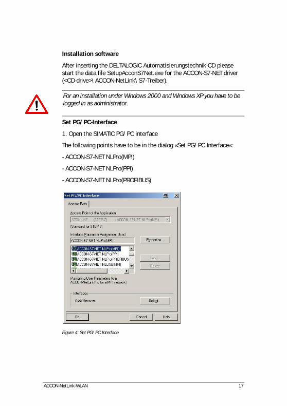
Configuration example of RFC1006 with ACCON AGLink
Figure 18: Configuration example for RFC1006
This configuration can be used for the following software packages:
• ACCON-AGLink Version 3.x and 4.0
• DELTALOGIC S7/S5-OPC-Server
• SPS-Analyzer AutoSPy
• ACCON-S7-Power-Tools
• ACCON-S7-EasyLog

ACCON-NetLink-WLAN 35
Use of RFC1006 with WinCC v 6.0
To parametrize a RFC1006 connection in WinCC, you have to create a new TCP/IP connection in the »SIMATIC S7 PROTOCOL SUITE«. The new connection is called »NetLink_PRO« here.
Figure 19: Create TCP/IP connection
Click on »Read« and you get to the following settings:
Figure 20: Connection parameters TCP/IP

ACCON-NetLink-WLAN 36
In this case the ACCON-NetLink-WLAN has the IP address 192.168.4.38. The target CPU with which should be communicated has the PROFIBUS address 49. The addressed mode is used, so the value for Rack and Slot can be checked up in the address conversion table in chapter »14 APPENDIX«.
But the connection still needs a variable. To do so, open the context menu of the connection with a right mouse click and choose »New tag…«.
Figure 21: Tag properties
In the »Tag properties« window you can choose the type of the variable (MB0_over_NetLink_PRO, here) via the button »Select«.

ACCON-NetLink-WLAN 37
Figure 22: Flag byte 0 is going to be projected
In the following screenshot you can see that there is now a new variable called »MB0_over_NETLink_PRO« under the point »NetLink_PRO«.
Figure 23: Connection »NETLINK_PRO«
If this variable is now included in the initial screen of the WinCC project, a connection will be established to the CPU with address 49 via the ACCON-NetLink-WLAN to access marker byte 0. Further variables of

ACCON-NetLink-WLAN 38
different types can, of course, be created and used according to the same scheme. It is also possible to create additional TCP/IP connections in order to communicate with more CPUs.
Rack/Slot Mode
Figure 24: Rack/Slot Mode
A special feature of the RFC1006 option is the Rack/Slot Mode. Using this function it is possible to access several CPUs which are on the same Rack (Multicomputing) via one bus address. A connection from a PROFIBUS-CP (z. B. CP342-5) to a S7 CPU is possible, too.
Only to the set station (PLC number) will be communicated to. This station forwards the data packages to the desired Rack/Slot.
To use this function, the following settings on the configuration page of the web interface have to be made:
• »Rack/Slot mode« (»ON«)
• At »Fix destination address for R/S mode« the address (PLC number) of the desired communication partner has to be entered. In this example »49«.

ACCON-NetLink-WLAN 39
9 THE WEB INTERFACE
The web interface of the ACCON-NetLink-WLAN can be used with any standard browser (e. g. Internet Explorer, Mozilla Firefox, Opera, etc.).
Start page
The welcome page of the ACCON-NetLink-WLAN is called with »http://ip-address«. (default ip: 192.168.4.49)
The web interface can be activated/deactivated via the configuration in the PG/PC interface
Via the welcome page you get to the following pages:
• Welcome page
• Configuration page
• Page for security settings
• Page to monitor variables
• Web site of the DELTALOGIC Automatisierungstechnik GmbH
Status page
The status page shows the currently used settings of the ACCON-NetLink-WLAN. You cannot change anything there.
This page provides the following information:
Device specific parameters:
Product name ACCON-NetLink-WLAN
Order number 161700-WLAN
Firmware name ACCON-NetLink-WLAN
Firmware version e. g. V2.10
Bios version e. g. V2.10
Serial number e. g. T00006262
MAC address e. g. 00:06:71:19:00:3E

ACCON-NetLink-WLAN 40
Device name The name which was stored in the ACCON-NetLink-WLAN is shown here.
Bus-specific parameters:
Station address If the ACCON-NetLink-WLAN is active on the bus, you have to enter the bus address here.
Bus parameters If the ACCON-NetLink-WLAN is active on the bus, the itemized bus parameter set is shown here.
Max. possible bus connections
Number of the at most simultaneously possible bus connections (12 at the moment).
List of active stationsIf the ACCON-NetLink-WLAN is active on the bus, the list of active stations is output here. The own address is displayed in red.
Number of used bus connections
If the ACCON-NetLink-WLAN has opened at least one bus connection, the amount of open connections is shown here.

ACCON-NetLink-WLAN 41
TCP/IP-specific parameters:
IP address Current IP address of the ACCON-NetLink-WLAN (e. g. 192.168.4.54).
Subnet mask Current subnet mask of the ACCON-NetLink-WLAN (e. g. 255.255.255.0).
Gateway Current standard gateway of the ACCON-NetLink-WLAN (e. g. 192.168.4.33).
DHCP status Shows if DHCP is activated or not
If DHCP is »ON« there is the additional information if DHCP was successful or if the parametrized default IP address is used.
Device name Free-selectable name for the ACCON-NetLink-WLAN
Max. possible IP connections
Number of the at most simultaneously possible IP connections (7 at the moment).
Communications port
Port number of the TCP/IP communications port (standard 7777).
Number of used TCP connections
If the ACCON-NetLink-WLAN has opened at least one TCP or RFC connection, the amount of open TCP connections is shown here.
RFC-1006-specific parameters
RFC1006 status Shows if RFC1006 is activated or not (»ON« oder »OFF«). If activated (»ON«) further parameters are visible..
The following parameters are only visible if RFC1006 is activated:
Bus autobaud ON/OFF
Shows if the bus parameters of the bus system should be detected automatically (»ON«) or if the stored parameters should be used to go online(»OFF«).
Own station address Shows the own station address. It is the address with which the ACCON-NetLink-WLAN participates in the bus cycle.
ACCON-NetLink-WLAN 42
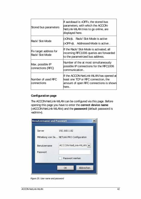
Stored bus parameters
If autobaud is »OFF«, the stored bus parameters, with which the ACCON-NetLink-WLAN tries to go online, are displayed here.
Rack/Slot-Mode (»ON«)è Rack/Slot-Mode is active
(»OFF«)è Addressed-Mode is active .
Fix target address for Rack/Slot-Mode
If the Rack/Slot-Mode is activated, all incoming RFC1006 queries are forwarded to the parametrized bus address.
Max. possible IP connections (RFC)
Number of the at most simultaneously possible IP connections for the RFC1006 communication..
Number of used RFC connections
If the ACCON-NetLink-WLAN has opened at least one TCP or RFC connection, the amount of open RFC connections is shown here..
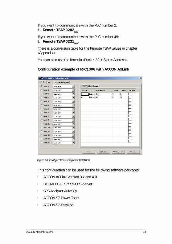
Configuration page
The ACCON-NetLink-WLAN can be configured via this page. Before opening this page you have to enter the correct device name (»ACCON-NetLink-WLAN«) and the password (default password is »admin«).
Figure 25: User name and password

ACCON-NetLink-WLAN 43
The user name and the password are case-sensitive !
The used standard values User name: ACCON-NetLink-WLAN Password: admin
After a successful authentication you have writing access on all parameters which are configurable via the driver interface of the ACCON-S7-NET driver.
Static IP address Used IP address if DHCP is deactivated or DHCP timeout elapsed.
Static subnet mask Used subnet mask if DHCP is deactivated or DHCP timeout elapsed.
Static gateway Used gateway if DHCP is deactivated or DHCP timeout elapsed.
Alternative NETLink Port
In addition to the standard port you can store a further user-definable port for the ACCON-NetLink-WLAN.
Device name Name consisting of alpha-numeric characters with a max. length of 20 characters.
DHCP status »ON« or »OFF«
DHCP timeout 30 to 65500 seconds
We status Web interface »ON« or »OFF«
New password Password with a maximum of 8 digits
Repeat new password Repeat password with a maximum of 8 digits
Autobaud
Using the option »Bus autobaud ON/OFF« you can set if the ACCON-NetLink-WLAN searches the bus parameters and goes online then, or the device uses the stored bus parameters when going on the bus.
»ON« oder »OFF« is possible.

ACCON-NetLink-WLAN 44
Own station address
The option »Own station address« shows with which bus address the ACCON-NetLink-WLAN has logged in on the bus.
The value for the station address can be in the range of »0« including »126«. But the chosen address must not be higher than the HSA (highest station address) and is not assigned to another device at the same bus.
Storing of given bus parameters
If the option »Bus autobaud ON/OFF« is deactivated (»OFF«), you have to fill in the parameter fields, belonging to the subitem »Stored bus parameters«, correctly. When parametrizing you have to keep in mind that with PROFIBUS all parameters are dependent from each other, e. g. if the baudrate is changed then all other parameters are changed, too.
With MPI all parameters are given except the baudrate. If a MPI connection is changed from 187,5 KBit/s to e. g. 12000 KBit/s all other parameters are unmodified.
Baudrate: Enter desired baudrate in KBit/s. Possible values are: 9,6; 19,2; 45,45; 93,75; 187,5; 500; 1500; 3000; 6000 and 12000.
HSA:
The highest station address is entered here. With MPI normally »31« and with PROFIBUS »126«. Values which are not equal to the default values can be used. All stations have to be adjusted equally.
Tslot_Init:
Using MPI this value is always »415«. With PROFIBUS the respective value has to be taken from the parametrization of the bus master (normally the CPU).
Ttr:
Using MPI this value is always »9984«. With PROFIBUS the respective value has to be taken from the parametrization of the bus master (normally the CPU).
Max. Tsdr:
Using MPI this value is always »400«. With PROFIBUS the respective value has to be taken from the parametrization of the bus master (normally the CPU).
ACCON-NetLink-WLAN 45
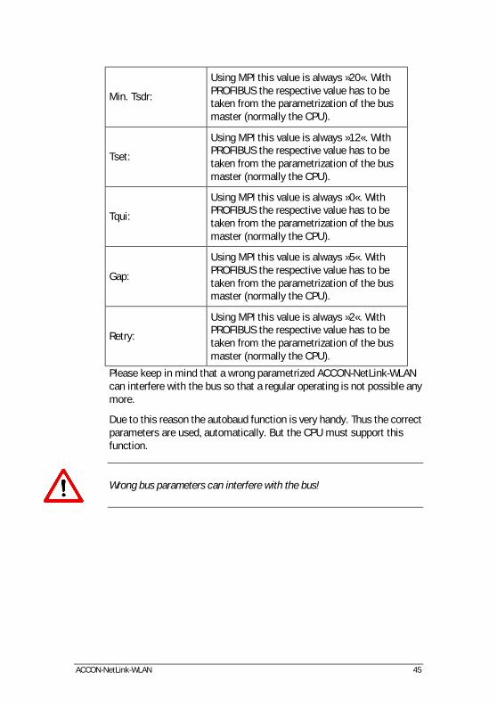
Min. Tsdr:
Using MPI this value is always »20«. With PROFIBUS the respective value has to be taken from the parametrization of the bus master (normally the CPU).
Tset:
Using MPI this value is always »12«. With PROFIBUS the respective value has to be taken from the parametrization of the bus master (normally the CPU).
Tqui:
Using MPI this value is always »0«. With PROFIBUS the respective value has to be taken from the parametrization of the bus master (normally the CPU).
Gap:
Using MPI this value is always »5«. With PROFIBUS the respective value has to be taken from the parametrization of the bus master (normally the CPU).
Retry:
Using MPI this value is always »2«. With PROFIBUS the respective value has to be taken from the parametrization of the bus master (normally the CPU).
Please keep in mind that a wrong parametrized ACCON-NetLink-WLAN can interfere with the bus so that a regular operating is not possible any more.
Due to this reason the autobaud function is very handy. Thus the correct parameters are used, automatically. But the CPU must support this function.
Wrong bus parameters can interfere with the bus!

ACCON-NetLink-WLAN 46
RFC-1006-specific parameters
RFC1006 status Shows if RFC1006 is activated or not (»ON« oder »OFF«). If activated (»ON«) further parameters are visible..
The following parameters are only visible if RFC1006 is activated:
Bus autobaud ON/OFF
Shows if the bus parameters of the bus system should be detected automatically (»ON«) or if the stored parameters should be used to go online(»OFF«).
Own station address Shows the own station address. It is the address with which the ACCON-NetLink-WLAN participates in the bus cycle.
Stored bus parameters
If autobaud is »OFF«, the stored bus parameters, with which the ACCON-NetLink-WLAN tries to go online, are displayed here.
Rack/Slot-Mode (»ON«)è Rack/Slot-Mode is active
(»OFF«)è Addressed-Mode is active .
Fix target address for Rack/Slot-Mode
If the Rack/Slot-Mode is activated, all incoming RFC1006 queries are forwarded to the parametrized bus address.
Entered changes can be undone with the button »Cancel«.
By clicking on »OK« the entered values are checked. If there is a wrong input a possible solution is shown. If all is correct, all changes are shown again and with a click on »OK« the values will be stored in the ACCON-NetLink-WLAN. To activate the new configuration, the ACCON-NetLink-WLAN will be restarted after saving the new parameters. If desired the ACCON-NetLink-WLAN can be activated remotely via the configuration interface. To do this click on »System Reset«.
ACCON-NetLink-WLAN 47
Security page
The security page contains rudimental TCP security settings. Before opening this page you have to enter the correct device name (»ACCON-NetLink-WLAN«) and the password (standard password is »admin«). Via the button »factory defaults« the ACCON-NetLink-WLAN can be set to its standard settings.
The used standard values User name: ACCON-NetLink-WLAN Password: admin
If the TCP-Access list is activated with »ON«, only TCP connections to the ACCON-NetLink-WLAN can be established which have been unlocked in the table »TCP address 1« to »TCP address 12« (whitelist).
Enter an IP address which has to be unlocked according to the following example: »192.168.4.36«. To deactivate it, enter »OFF«.
TCP/IP addresses which are not indicated here, have only read access on the web interface and cannot change the configuration. An access with ACCON-S7-NET is limited, too.
If you want to avoid unauthorized use you must not add possible proxy server in company networks to the list. Otherwise a secure use of the ACCON-NetLink-WLAN is only limited.
To undo changes just press the »Cancel« button.
By clicking on »OK« the entered values will be checked. If there is a wrong input a possible solution is shown. If all is correct, all changes are shown again and with a click on »OK« the values will be stored in the ACCON-NetLink-WLAN. To activate the new configuration, the ACCON-NetLink-WLAN will be restarted after saving the new parameters. If desired the ACCON-NetLink-WLAN can be activated remotely via the configuration interface. To do this click on »System Reset«. It is possible the restore the ACCON-NetLink's default values via the button »Factory default«. All user-defined settings will be deleted.

ACCON-NetLink-WLAN 48
WLAN configuration settings
WLAN ON/OFF (»ON«)è WLAN mode is on.
(»OFF«)è WLAN mode is off.
Infastructure Option comes into action when NetLink WLAN is supposed to log on to an access point.
- Network name (SSID) SSID des AccessPoints (1-32 digits)
Ad Hoc Options come into action when NetLink WLAN is supposed to log on directly to a WLAN module.
- Station name Station name of ACCON-NetLink-WLAN in the Ad Hoc mode
Channel
Channel on which NetLink WLAN sends in the ad hoc mode. The channel can be chosen freely from 1 to 13. Only 11 channels are available in the USA!

ACCON-NetLink-WLAN 49
WLAN security settings
Security Here you can chose the security standard WEP / WPA or WPA 2.
- NONE No encoding (insecure)
- WEP Data is encoded according to WEP standard (relatively insecure).
- WPA Data is encoded according to WPA standard (medium security).
- WPA2/802.11i Data is encoded according to WPA2 standard (highest security).
Authentication
Here you can set the type of client authentication in the WEP security standard.
Shared or Open/None
(Recommendation: OPEN/NONE)
Encryption
Here you can set the type of encoding. WEP: 64/128 BIT WPA: TKIP / TKIP + WEP WPA2: - AES - AES + TKIP - AES + WEP - TKIP - TKIP + WEP
Key type Here you can chose passphrase or HEX depending on the type of encoding.
Key
Here you can enter the key depending on the type of decoding. WEP 64 Bit (HEX): 10 Zeichen WEP 128 Bit (HEX): 26 Zeichen WPA (HEX): 64 Zeichen WPA (PASSPHRASE): 1-63 ZeichenWPA2 (HEX): 64 Zeichen WPA2 (PASSPHRASE): 1-63 Zeichen

ACCON-NetLink-WLAN 50
Monitor variables
From the firmware version 1.50 the function »Observe variables« is unlocked in the ACCON-NetLink-WLAN. This function is supported in the RFC1006 function via the web interface. The activation is described in chapter »8«
Parameters for monitoring variables:
MPI Address With the help of the dropdown menu an active MPI/PROFIBUS address (S7-CPU) is selected.
Number of Variables For a better overview the number of the desired variables can be selected between 1 and 10.
No. Continuous numeration.
Address Area The following items are supported: AB, AW, AD, EB, EW, ED, MB, MW, MD, DBB, DBW, DBD, Counter and Timer.
Address Index*
Address of the bytes which want to be shown. * Data modules in the nomenclature »Data module offset« e. g.: 108.10
Result Value The output value of a pressed button can be seen here.
Display Format Possible display modes are decimal, hexadecimal oder binary
Description Free-selectable description (max. 32 characters)
To show the desired values the buttons »1x fetch«, for a refresh once, or »cyclic fetch«, for a permanent online request, are available.
With »Save Configuration« the created mask including all set variables and their descriptions can be stored in the ACCON-NetLink-WLAN.
The refresh rate is set to 0,5 seconds. If several stations use this functions from the TCP/IP side, then there is always only one connection resource reserved in the ACCON-NetLink-WLAN. During the additional data exchange via MPI/PROFIBUS the »Observe Variables«

ACCON-NetLink-WLAN 51
function has the lowest priority. Thus the refresh rate in the web interface is dependent from the parallel bus load.

ACCON-NetLink-WLAN 52
10 REMOTE MAINTENANCE WITH THE ACCON-NETLINK-WLAN
If the ACCON-NetLink-WLAN should be used for remote maintenance all involved network administrators of both locations have to be consulted.
There different ways of remote maintenance via a WAN (Wide Area Network):
Allocation of an own and public IP address with a direct connection to the network:
Advantages Disadvantages
The administrator does not need to intervene
Not many global addresses available
Fast to realize Additional network with a direct WAN access is necessary
Not secure
Use behind a router via NAT:
Advantages Disadvantages
The administrator can take steps that the connection is not visible/usable for everyone from the outside
Network administrators have to parametrize router and firewalls between the involved communication partners
Can be integrated into a consisting infrastructure

ACCON-NetLink-WLAN 53
Figure 26: Remote maintenance via Internet
If more than one ACCON-NetLink-WLAN is used behind a router, you have to activate »Internet remote maintenance« at the stations and every station must have its own port address. Furthermore the router has to support NAPT (Network Address and Port Address Translation) respectively PAT (Port Address Translation).
Use of a dial-in router (e. g. MoRoS):
Advantages Disadvantages
Easy to realize if a telephone connection is available
Additional costs through telephone charges
Loss of performance due to a low bandwidth

ACCON-NetLink-WLAN 54
11 TROUBLE SHOOTING
Error Cause Solution
Power LED does not light
-ACCON-NetLink-WLAN has no voltage supply
-The used MPI bushing has not the necessary 24 VDC
- Plug MPI/PROFIBUS cable on PLC interface
- Apply 24 VDC externally
Active LED is blinking red
ACCON-NetLink-WLAN exception error on Ethernet side
Plug MPI/PROFIBUS cable again on the PLC interface
Connect LED is blinking red
ACCON-NetLink-WLAN exception error on MPI/PROFIBUS side
Plug MPI/PROFIBUS cable again on the PLC interface
Link LED does not light green
No connection to the Ethernet
Check Ethernet connection
Configuration of the ACCON-NetLink-WLAN via ACCON-S7-NET
The message »ACCON-NetLink-WLAN cannot be parametrized now.« appears
ACCON-NetLink-WLAN is active on the bus during parametrization
ACCON-NetLink-WLAN has to be inactive during parametrization
The message »Wrong password« appears
Password incorrect and/or parametrization time exceeded
Enter correct password and mind parametrization time
Setting TCP/IP parameters
No ACCON-NetLink-WLAN is reachable via the entered IP address
-ACCON-NetLink-WLAN is not online or still starting -IP configuration of PC and ACCON-NetLink-WLAN are not identical
-Activate ACCON-NetLink-WLAN or complete starting procedure -PC and ACCON-NetLink-WLAN have to be in the same

ACCON-NetLink-WLAN 55
not identical network segment
ACCON-NetLink-WLAN not reachable
Ports have to be released in the firewall
To search the ACCON-NetLink-WLAN the UDP ports 25342 and 25343 and for the communication the TCP/IP port 7777 have to be released. Port 7777 must always be released.
The program Starter® has problems when accessing a Micromaster drive
Failure and application monitoring too low
Increase failure monitoring to 200ms and application monitoring to 5000ms

ACCON-NetLink-WLAN 56
12 FREQUENTLY ASKED QUESTIONS
Q: I do not know my PC's IP address.
A: Use the prompt and enter the command »ipconfig« to gain information about your Ethernet interface.
Figure 27: ipconfig
Q: The configuration tool as well as the web interface asks for a password. But I did not enter any password.
A: The ACCON-NetLink-WLAN must have a password. If no password is set, the standard password is »admin«.
Q: There are no dialog settings in the Simatic Manager.
A: When you installed the ACCON-S7-NET driver for the first time you have to add it to the PG/PC interfaces, too. Make sure that you have administrator rights when installing the driver. After a successful installation you have to reboot your system. Simatic Manager Version 5.1 is minimum!
Q: It is not possible to go online when the adapter is put on the PROFIBUS.
A: If possible use the autobaud function. If not desired or possible you have to check the Profibus’ timing parameters in the STEP7 project planning. Via the »Bus Parameters« button you can enlist the read off values into the extended bus parameter settings. You have to increase the »TRT« (Target Rotation Time) parameter in the ACCON-NetLink-WLAN as well as on the PLC.

ACCON-NetLink-WLAN 57
Q: Sometimes MPI or PROFIBUS connections with high baud rates are getting disconnected although the ACCON-NetLink-WLAN is put on the PLC and no other users are connected.
A: Be sure that the bus is correctly terminated. Even though the ACCON-NetLink-WLAN is the only device connected to the bus in addition to the PLC. You have to insert the final resistor. Above all high baud rates can be interfered.
Q: If I set the ACCON-NetLink-WLAN to autobaud in the PG/PC interface and try to go online, the active LED lights up briefly before a message appears telling me that the bus parameters cannot be determined.
A: Please deactivate the autobaud function in the NETLink-S7-NET driver (PG/PC interface) and set the correct baud rate and the correct profile.
Q: I enabled the RFC function the web interface and would like the ACCON-NetLink-WLAN to go on the bus using autobaud. Unfortunately, the active LED just flashes but no communication is possible via my visualization system.
A: Please deactivate the autobaud function in the web interface of the ACCON-NetLink-WLAN and set the correct baud rate with the corresponding bus parameters.
Q: I have read that the ACCON-NetLink-WLAN can communicate with up to seven PCs at the same time. But I can’t manage to query a status of my automation system from more than six PCs at once.
A: A total of seven TCP connections are available that can be used at the same time. However, please note that only up to six connections can be used at once per type of connection (NETLink-S7-NET or RFC1006 connections are possible). The purpose of this is to keep one connection channel free for the other protocol in each case.
Q: I am using the rack/slot mode of the RFC1006 interface and have specified address 2 for my existing PLC in the web interface in »Fix destination address for R/S mode«. Although the ACCON-NetLink-WLAN online is active (active LED lights up), my visualization system tells me that no connection can be established.
A: Make sure you have assigned the correct values to rack and slot in the parametrization. Look for chapter »8«.
Q: I would like to use addressed mode of the RFC1006 interface (rack/slot mode = OFF) so I can access several PLCs on the same bus.

ACCON-NetLink-WLAN 58
Unfortunately, I am not sure how to parameterize the fields rack and slot in the visualization used.
A: If addressed mode is used, a combination of rack and slot specifies the destination address of the automation system.
Q: If I mix RFC1006 connections and connections via the STEP7 driver, the connection sometimes breaks off or error messages appear saying that it is not possible to establish a connection.
A: For communication with S7-300 modules it may be necessary to parameterize the communication resources. The user can influence the allocation of existing »Connection Resources« under object properties of the PLC in the hardware configuration.

ACCON-NetLink-WLAN 59
13 TECHNICAL DATA
Supported operating systems No restrictions (the driver for SIMATIC ACCON-S7-NET is only compatible with Windows 2000, XP, 2003, Vista)
Hardware requirements Ethernet interface and TCP/IP protocol
Supported PLCs S7-200, S7-300, S7-400
Weight in kg ca. 0,28
Dimensions (W x H x D) in mm 68 x 133 x 30
Protection type IP 20
Voltage supply 24 VDC ± 25 %
External voltage supply possible
Yes
Power consumption Max. 200 mA
Galvanically separated Yes
Operating temperature 0 °C to 60 °C
Temperature storage/ transport
-20 °C to 90 °C
Relative humidity 5 % to 85 % at 30 °C (no bedewing)
Connection cable to the PLC Cable mounted stationary, active (no spur line, 1,2 m)
Connection cable to the PC Patch cable (Ethernet, straight, 3 m)
Supported bus profiles MPI, DP, standard, Universal (DP/FMS), user-defined with automatic detection, PPI
Supported transmission rate of the bus connection to the PLC
9,6 KBit/s to 12 MBit/s with automatic detection
Supported transmission rates 10/100 MBit/s with automatic

ACCON-NetLink-WLAN 60
Ethernet detection
Supported transmission rate WLAN
max. 54 MBit/s
Antenna connector RP-SMA (male; with PIN)
WLAN-Typ 802.11b und 802.11g (2,4 GHz-Band)
Transmission power 14dBm (+1,5/-1,0)
Wireless-security-methods WEP, WPA, WPA2
Max. number of connections to TCP/IP
16
Max. number of connections to MPI, PROFIBUS, PPI
12
Supported software ACCON-S7-EasyLog, ACCON-AGLink, DELTALOGIC S7/S5-OPC-Server. With the driver for SIMATIC ACCON-S7-NET the following software can be used; SIMATIC Manager from V5.3, WinCC 6.0, WinCC flexible, ProTool, STEP7-Micro/WIN
Table 6: Technical data

ACCON-NetLink-WLAN 61
Pin assignment
Assignment MPI/PROFIBUS interface
Port Signal Meaning
1 - Not used
2 GND Ground/ voltage supply (looped-through)
3 RxD / TxD-P Received/transmission data-P
4 - Not used
5 DGND Ground for bus termination (looped-through)
6 DVCC 5 VDC for bus termination (looped-through)
7 VCC 24 VDC power supply (looped-through)
8 RxD / TxD-N Received/transmission data -N
9 - Not used

ACCON-NetLink-WLAN 62
Assignment Ethernet interface (Host-Interface)
Port Signal Meaning
1 TX+ transmission data
2 TX- transmission data
3 RX+ Received data
4 - Not used
5 - Not used
6 RX- Received data
7 - Not used
8 - Not used
The ACCON-NetLink-WLAN is supplied with a 3 meter patch cable (straight) category 5.
The maximum length between two TCP/IP interfaces must not exceed 100 meter according to IEEE802.
If there are distances greater than 100 meters you have to use repeater or switches.
Voltage bushing
When using an external voltage feed you have to mind the correct polarity and the voltage.

ACCON-NetLink-WLAN 63
14 APPENDIX
Address conversion table
The following table serves as a parametrization help for the addressed mode. The bus address can be converted to Rack/Slot or TSAP, e. g. the controller with the bus address 49 is addressed by Rack 1 and Slot 17 or with the TSAP 0231.
Bus-adr.
Rack Slot TSAP Bus-adr.
Rack Slot TSAP
0 0 0 0200 64 2 0 0240
1 0 1 0201 65 2 1 0241
2 0 2 0202 66 2 2 0242
3 0 3 0203 67 2 3 0243
4 0 4 0204 68 2 4 0244
5 0 5 0205 69 2 5 0245
6 0 6 0206 70 2 6 0246
7 0 7 0207 71 2 7 0247
8 0 8 0208 72 2 8 0248
9 0 9 0209 73 2 9 0249
10 0 10 020A 74 2 10 024A
11 0 11 020B 75 2 11 024B
12 0 12 020C 76 2 12 024C
13 0 13 020D 77 2 13 024D
14 0 14 020E 78 2 14 024E
15 0 15 020F 79 2 15 024F
16 0 16 0210 80 2 16 0250
17 0 17 0211 81 2 17 0251
18 0 18 0212 82 2 18 0252
19 0 19 0213 83 2 19 0253
20 0 20 0214 84 2 20 0254

ACCON-NetLink-WLAN 64
Bus-adr.
Rack Slot TSAP Bus-adr.
Rack Slot TSAP
21 0 21 0215 85 2 21 0255
22 0 22 0216 86 2 22 0256
23 0 23 0217 87 2 23 0257
24 0 24 0218 88 2 24 0258
25 0 25 0219 89 2 25 0259
26 0 26 021A 90 2 26 025A
27 0 27 021B 91 2 27 025B
28 0 28 021C 92 2 28 025C
29 0 29 021E 93 2 29 025D
30 0 30 021F 94 2 30 025E
31 0 31 0220 95 2 31 025F
32 1 0 0220 96 3 0 0260
33 1 1 0221 97 3 1 0261
34 1 2 0222 98 3 2 0262
35 1 3 0223 99 3 3 0263
36 1 4 0224 100 3 4 0264
37 1 5 0225 101 3 5 0265
38 1 6 0226 102 3 6 0266
39 1 7 0227 103 3 7 0267
40 1 8 0228 104 3 8 0268
41 1 9 0229 105 3 9 0269
42 1 10 022A 106 3 10 026A
43 1 11 022B 107 3 11 026B
44 1 12 022C 108 3 12 026C
45 1 13 022D 109 3 13 026D
46 1 14 022E 110 3 14 026E
47 1 15 022F 111 3 15 026F

ACCON-NetLink-WLAN 65
Bus-adr.
Rack Slot TSAP Bus-adr.
Rack Slot TSAP
48 1 16 0230 112 3 16 0270
49 1 17 0231 113 3 17 0271
50 1 18 0232 114 3 18 0272
51 1 19 0233 115 3 19 0273
52 1 20 0234 116 3 20 0274
53 1 21 0235 117 3 21 0275
54 1 22 0236 118 3 22 0276
55 1 23 0237 119 3 23 0277
56 1 24 0238 120 3 24 0278
57 1 25 0239 121 3 25 0279
58 1 26 023A 122 3 26 027A
59 1 27 023B 123 3 27 027B
60 1 28 023C 124 3 28 027C
61 1 29 023D 125 3 29 027D
62 1 30 023E 126 3 30 027E
63 1 31 023F
Table 7: Conversion table
Updates on the Internet:
You can find actual drivers and firmware versions on www.deltalogic.de in the download section.