Embed Size (px)
Citation preview
ACCIDENTAL ANALOGAbstract
A designer of a post-frame buildingmust compute the deformations, inter-nal forces and stresses of the post-framemembers, diaphragms and shear walls.This analysis is based on the principlethat stiffer elements will resist moreof the load. The process begins withthe development mathematical modelswhich accurately reflect the performanceof the structural element. These modelsare commonly called "analogs." Thisarticle reviews the practice of model-ing a post embedded in soil as fixed atgrade and then using the formulas inthe International Building Code to checkthe embedment depth. It argues that thispractice:
• violates the logical principle of con-tradiction;
• commits the logical fallacy of assum-ing what it is attempting to determine;
• is justified by neither expediency norexperience;
• introduces significant error into theanalysis of the post-frame building.
Review of the IBCEmbedment Formulas
Section 1807.3 of the 2009 IBC coversembedded posts and poles. This sectiondivides embedded posts into two condi-tions: non-constrained and constrained.A non-constrained post is one that hasnothing to push against at grade and aconstrained post does. In the normalpost-frame building with a floor slab,the posts on the side the wind is blow-ing against can push against the floorslab so they are constrained. Unless theposts are somehow pinned to the slab,the posts on the opposite wall are non-constrained. Equation 18-1 provides aminimum embedment depth for a non-constrained post and Equations 18-2 and18-3 provide the minimum embedmentdepth for constrained post.
Meador (1997) stated that these for-mulas were derived using the first threefollowing assumptions. McGuire (1998)pointed out the fourth assumption.
Figure 1
LOAD
The "accident" - the forces at grade for asimple cantilever are the same for a fixedbase analog as for a post embedded inan elastic material. This led designersto rashly assume you could model anembedded post as fixed at the base.
LOAD 4 -/*-
SHEAR
BENDING
FIXED- POST INBASE ELASTIC
MATERIALSOILPRESSURE?
FIGURE 1NON-CONSTRAINED POSTS
SOILPRESSURE
1. The soil resistance to deformation isproportional to displacement.
2. The resistance to deformationincreases linearly with depth belowgrade.
3. The post is rigid below grade.4. The shear force at grade acts to
increase the effect of the moment atgrade, not to decrease it.
In "Pole Building Design" by DonaldPatterson, first published in 1957,Patterson describes the minimumembedment depth as "The depth of setrequired to prevent the rotation of a can-
tilever pole acted on by a lateral force"and the depth "required to prevent objec-tionable deflection of the pole axis fromits original position." Patterson's illustra-tions DO NOT show a fixed base, ratherthey show a member cantilevering froma material as described in assumptions 1through 3 above under a load describedin assumption 4. See Figure 1. Althoughcontrolling deflections is his statedobjective, he presents no method of esti-mating these deflections. He implies thatmembers meeting the criteria he presentswill have acceptable deflections.
www.FrameBuildingNews.com 53

Table 1: Building parameters & wind pressures
Building Width x Length x Height, Roof PitchExternal Windward Wall PressureExternal Leeward Wall PressureInternal PressureNet Wind Load on RoofPost Spacing & EmbedmentPost Description & Dressed SizePost Modulus of Elasticity adjusted for MoistureEffective width, BeGrade Condition WindwardGrade Condition LeewardSoil Type per ASABE EP-486.1 Table 1Soil Lateral Pressure per unit Depth, SAdjusted Lateral Pressure for Wind & IsolationConstant of Lateral Soil Reaction, nn
In Plane Stiffness of Roof Diaphragm, CpEnd Wall Stiffness
40' x 80' x14', 4/1210.61 psf-3.98 psf+/- 2.81 psf60.17 plf8' oc, 48" Embedment3 ply 2x6 #1 SP w/glued finger joints, 4.31" x 5.31"1,700,000 psi x 0.9 = 1,530,000 psi0.63 ftConstrainedNon-constrainedType 4 Firm200 psf/ft200x1. 33x2 = 532 psf/ft10,000 lbf/ftA414,160 pli14,160 pli
IBC Section 1807.3 contains no expres-sions for predicting the deflections ofembedded posts or poles. However, it isinteresting that 1802.3.1 2. reads "Postsembedded in earth shall not be used toprovide lateral support for structural ornonstructural materials such as plaster,masonry or concrete unless bracing isprovided that develops the limited deflec-tion required." To this day the embed-ment equations continue to consider onlyforces and pressures, not deflections.
In summary, one can conclude thatthe formulas in the IBC are based on soilas an elastic material that increases instrength and stiffness with depth belowgrade but they give no guidance to deter-mine deformations. Further, becausethey provide no method of calculatingdeformations, we can conclude that theywere derived to apply in those situationswhere deformations do not have to becalculated in order to determine the dis-tribution of forces within the structure.Examples of such structures are billboardsigns and flag poles.
Fixed Base AccidentLateral load is resisted in a post-frame
building by the complex interaction ofpost-frames and diaphragms. To deter-mine the forces resisted by each element,it is certainly necessary to calculatedeflections. Because of the "accident"that the forces at grade are the same fora fixed base cantilever as for a cantilever
from elastic material, one can see howit was natural to assume and use a fixedbase analog in the post-frame analy-sis. This was especially true because theengineering profession is divided into
"building people" and "soils people."A structural engineer designs the
building and a geotechnical engineerdetermines the allowable soil designcriteria. In post-frame building designthis division of labor does not work well,because the performance of the buildingabove grade is so intimately dependenton the performance of the part of thebuilding below grade.
In spite of the fact that any "go-fer"on a building crew can tell you that apost-frame building is not the same asa billboard sign, most of the "buildingpeople" decided to assume that the postsare fixed at grade because it made theircalculations easier and they didn't haveto try and understand the complexitiesof soil modeled as an elastic material. Itis the contention of this paper that thisdevelopment was an "accident" of his-tory and that designers fell into using itwithout seriously examining the impli-cations of its use. They just assumed thatbecause the fixed base analog gives thesame forces as a cantilever from an elas-tic material it was adequate. The truth isthat it leads to erroneous results whenthe designer needs to analyze a structuremore complex than a bill board sign suchas a post-frame building.
Aristotle, Aquinas, etc.The principle of contradiction is the
axiom or law of thought that a thing cannotbe and not be at the same time, or a thingmust either be or not be, or the same attri-bute cannot at the same time be affirmedand denied of the same subject. This prin-ciple is fundamental in both Western andEastern philosophies (although still debat-ed in quantum mechanics.) An example isthat the statements "That cat is dead" and
"That cat is alive" cannot both be true atthe same time. That cat has to either beeither dead or alive.
The first assumption in the deriva-tion of the embedment formulas is thatthe soil's resistance to deformation isproportional to displacement. A fixedbase analog is perfectly non-propor-tional. Regardless of the loads applied toit, deformation is always zero. Thus itsresistance to deformation is infinite. Itis a contradiction in the same analysis toassume that soil resistance to deforma-tion is at the same time both proportion-al to displacement and infinite. It simplydoes not make sense.
The second logical error in using thefixed base analog in post-frame analy-sis is that it is circular. Circular reason-ing is the logical error of assuming whatyou are trying to prove. An example is:"Only crooks run for public office, thusall elected officials are crooks." The con-clusion is only a restatement of the initial
FRAME BUILDING NEWS I JANUARY2012

•NOLOGY
Table 2: Analysis Comparison Deflection & Roof Shear
Kpw, Windward StiffnessRew, Windward Eave LoadKpl, Leeward StiffnessRel, Leeward Eave LoadKp totalRe total including roofMaximum Frame DeflectionMaximum Roof Shear
Fixed Base Analog51.8pli446.3 Ibf51.8 pli-167.4 Ibf103.6 pli1095.6 Ibf1.03"4028.5 Ibf
Spring Analog33.6 pli497.7 Ibf9.6 pli-239.5 Ibf43.2 pli1218.6 Ibf1.20"5310 Ibf
Bohnhoff's Analog39.9 pli480.5 Ibf10.6 pli-240.4 Ibf50.5 pli1202.3 Ibf1.18"5740 Ibf
Table 3: Analysis Comparison Leeward Non-constrained Post
External + internal windRel, ext + int windLoad resisted by framePost Shear at EavePost Shear at GradeMax Moment Mid HeightMoment at GradeContraflow above GradePost embedment depth
Fixed Base Analog54.3 plf-284.6 Ibf53.4 Ibf (51. 8 pli x 1.03")232.2 Ibf528.3 Ibf496.5 ft-lbf-2070.6 ft-lbfYES4.53 ft(Section 6.5.1 EP-486.1)
Spring Analog54.3 plf-407.2 Ibf10 Ibf (trial& error)397.2 Ibf (trial & error)363.8 Ibf (trial & error)1452,7 ft-lbf233.5 ft-lbfNO4ftnh x A at 16" below grade= 282 psf/ft
Bohnhoff's Analog54.3 plf-408.7 Ibf12. 5 Ibf (10.6 pli x 1.18")395.3 Ibf364.9 Ibf1438.9 ft-lbf259 ft-lbfNO4ftnh x A at 16" below grade= 320 psf/ft
premise. The use of the fixed base analogis like this in that it produces the resultthat the shear and moment at grade willalways reinforce, never counteract, eachother. McGuire (1998) pointed out thatthis assumption is inherent in the deri-vation of the post embedment formulas.They assume the soil pressure distribu-tion which is characteristic of a simplecantilever. Restated explicitly it is: "Thefixed base analog always predicts thatembedded posts behave like simple can-tilevered posts, thus all posts behave likesimple cantilevers."
This is nonsense. The reason an ana-log is developed is to determine theinternal forces in a member by calculat-ing its deformations. With a fixed baseanalog, zero deformation correspondsto any value from zero stress to infinitestress. The very first test of a model ofan embedded post is how well it predictsthe pressure distribution in the soil. Thefixed base analog fails this task miserably.
Expedient DesignFortunately, the IBC in Section 2306.1
adoptsASABEEP-486.1.ThisEngineeringPractice implicitly (if not explicitly) gives
a designer the tools he needs to use amore rational analog which is consis-tent with the assumption that soil is anelastic material and its strength and stiff-ness increase with depth below grade. Dr.David Bohnhoff (1992) presented sucha rational analog in a paper publishedalmost 20 years ago. Bohnhoff presentedequations "for estimating frame stiffnessand eave loads for diaphragm analysis ofpost-frame buildings. Those equationsdeveloped for embedded posts take intoaccount soil stiffness." Bohnhoff beganby considering an embedded post analogconsisting of two pinned supports belowgrade which are unyielding in the hori-zontal direction. Although this analoghas not been directly considered hereto-fore in this paper, one can see that it is inmany ways similar to a fixed base analog.Bohnhoff stated: "This analog does notallow realistic post rotation and ignoresthe influence of soil properties on framestiffness." As a remedy, Bohnhoff wentback to the initial assumptions of theembedment formulas and derived equa-tions for frame stiffness using the soil asan elastic material.
Later McGuire (1998) used the work of
Bohnhoff and Meador (1997) to developan analog modeling soil as a series ofsprings supporting the post below grade.The springs were calibrated to agree withthe increasingly stiff soil as embedmentdepth increased. This analog was suit-able for use in a matrix analysis computerprogram. McGuire's results confirmedBohnhoff's equations, and McGuire wasable to identify the error introduced byassumption #3 that the post is rigid belowgrade. Since most designers use matrixanalysis programs, it would seem that thestage was set before the turn of the millen-nium for the fixed base analog to becomeextinct.
However, it is a fact of life that to beexpedient a structural design methodmust be not only accurate, but efficient.The work it takes to get the result mustnot be burdensome, and it is burdensometo set up each embedded post as sup-ported by a series of springs in a matrixanalysis program. (But there is a limitto how much accuracy can be ethicallysacrificed for the sake of speed.) Somemostly unsuccessful work was done todevelop a less burdensome spring modelfor use in matrix analysis programs. At
www.FrameBuildingNews.com

least this author abandoned this projectbecause he found it unnecessary. Matrixanalysis programs are a powerful tool forengineers. They are general and can beapplied to all sorts of strange situations.But most of the time they are like usingyour deer rifle to hunt squirrels — theyare way too much gun. The vast majorityof post-frame buildings can be quicklyanalyzed using Bohnhoff's original soilstiffness equations programmed into asimple spreadsheet. These values can beentered into the Diaphragm and FrameInspection program, or in the samespreadsheet compatible eave deflectionscan easily be solved using the SimpleBeam Analogy equations presented inSection 9.5.3 of the Post-Frame BuildingDesign Manual (2000). If used withinthe limits for which they were developed,these equations give the same results asmatrix analysis methods such as DAFI(Bohnhoff, 1992).
ErrorsTo get a sense of the differences in
results, let's consider the lateral windload analysis of 40' wide x 80' long x 14'tall post-frame building as described inTable 1. Further let's analyze it with 3different analogs: fixed base, Bohnhoff'sand the spring model. The frame stiffnessof the fixed base and the spring analogswere calculated using PPSA4 (Triche andSuddarth, 1993). Compatible deflectionswere calculated using DAFI (Bohnhoff,1992). Table 2 summarizes the calculateddeflections and roof shears. Table 3 is acomparative analysis of the leeward non-constrained post at the point of maxi-mum roof diaphragm deflection. Sinceinternal pressures cancel and produceno net lateral force, deflections were cal-culated using the external wind only. Inthe leeward post analysis, positive windinternal pressure has been added to theexternal wind pressures.
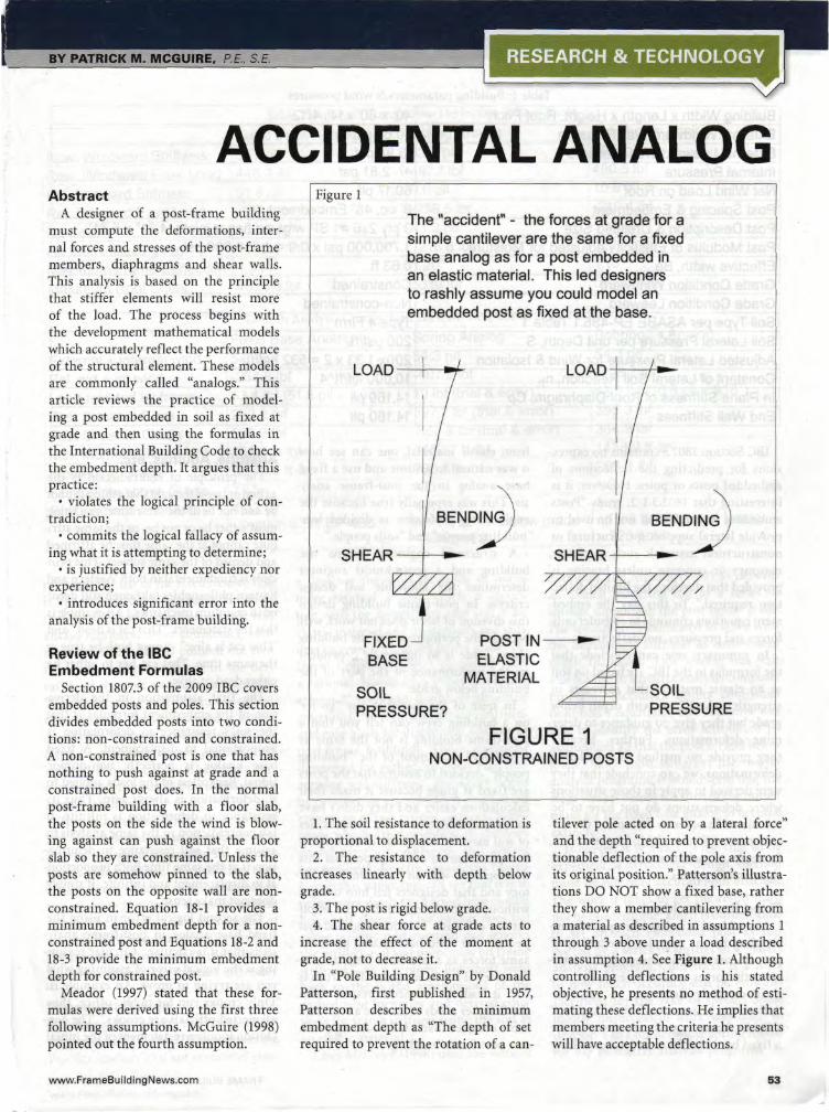
Table 3 shows that using a fixed baseanalog leads to an underestimation of thepositive moment in the leeward post ofalmost 200 percent. Although the maxi-mum moment in the fixed base analog isstill larger than in the other two analogs,location does matter. At the base of thepost, it is generally accepted that the postis braced against buckling under com-
Double curvaturewith contraflexure
Single curvaturewithout contraflexure
RESTRAINT fromroof diaphragm
BENDING
SHEAR
FIXED-BASE
SOILPRESSURE?
CURVATURE
SHEAR
POST INELASTIC
MATERIAL
PRESSURE
FIGURE 2NON-CONSTRAINED POSTS
pression, whereas at mid-height it is not.The larger base moments predicted by
the fixed base analog would also lead thedesigner to conclude that for this exam-ple, 4' is not an adequate embedmentdepth to resist lateral loads, whereas theother two analogs show that 4' embed-ment is more than adequate.
Finally, the point of contraflexurepredicted by the fixed base analog couldtempt a designer to locate a post splice atthis point and neglect bending. The othertwo analogs show that there is no point ofcontraflexure above grade so that bendingmust be considered at all locations.
Figure 2 illustrates this result.
ConclusionAnalogs must not presume, but predict.
References•Bohnhoff, D.R., 1992, Estimating frame
stiffness and eave loads for diaphragm
analysis of post-frame buildings,Trans. ASAE, 35(3): 1043-1054.
, 1992, ExpandingDiaphragm Analysis for Post-FrameBuildings, Applied Engineering inAgriculture, 8(4):509-517.
International Building Code, 2009,International Code Council.
Meador, N.F., 1997, Mathematical modelsfor lateral resistance of post foundations,Trans. ASABE, 40(1): 191-201.
McGuire, P.M., 1998, Overlooked assump-tion in non-constrained post embedment,Prac. Per. on Struct. Des. Cons.,ASCE3(l):19-24.
Patterson, D., 1957, Pole Building Design,American Wood Preservers Institute.
Post-Frame Building Design Manual,2000, National Frame BuildersAssociation.
Triche, M.H., and S. Suddarth, 1993,Purdue Plane Structure Analyzer 4,Purdue Research Foundation.
56 FRAME BUILDING NEWS I JANUARY2012