Embed Size (px)
Citation preview

ACCELEROMETER-BASED CHARACTER RECOGNITION
PEN
Kyle Buchanan
Theodore Pham
James Chang
Group #2
Summary:
The goal was to create a wireless pen that utilizes an accelerometer and pattern recognition
to achieve a high reliability handwriting recognition program.

2
Table of Contents Abstract .................................................................................................................................................... 3
Functional requirements of project .................................................................................................... 3
Design and description of operation ................................................................................................... 4 BOM .......................................................................................................................................................... 5
Reusable Design Units ........................................................................................................................... 8 All IO Signals ........................................................................................................................................... 9
Datasheets .............................................................................................................................................. 12
Background Reading .......................................................................................................................... 13 Software design .................................................................................................................................... 14
Test plan ................................................................................................................................................ 15 Results of experiments and characterization ................................................................................. 17
Safety ...................................................................................................................................................... 19
Environmental Impact ....................................................................................................................... 19 Sustainability ........................................................................................................................................ 20
Optional integrated circuit design proposal .................................................................................. 20
Quick Start Manual ............................................................................................................................ 20 Future Work ......................................................................................................................................... 22
Appendix A ........................................................................................................................................... 22 References ............................................................................................................................................. 23
Source code section .............................................................................................................................. 28
Appendix B ............................................................................................................................................ 31

3
Abstract: This project’s aim was to create a wireless pen that can perform highly reliable handwriting recognition. The pen uses a triaxial accelerometer to keep track of acceleration patterns and then sends these readings, via wireless XBee communication, to an Altera DE2 FPGA board to be processed. The transmission of readings is controlled by a trigger switch which, when pressed, tells the microcontroller to transmit the data. The pattern templates are stored on SD card memory for comparison to patterns received after calibration. The patterns received after calibrations are processed using Dynamic Time Warping to see which shape’s acceleration patterns it most closely resembles. This shape’s name is then printed out to the LCD. These templates represent one of 4 shapes: circle, triangle, checkmark, or vertical line. Functional requirements of project: Functionality Features: - Recognition of shapes, symbols, and numbers on a flat surface
- Partially met, only shapes were recognized. Implemented recognition of 4 shapes (line, checkmark, triangle, and circle). It was not 100% accurate (~75% accurate, user dependant).
- Wireless communication of written character from pen to board - Met. Proper data was received and analyzed. - Incorporates an accelerometer to measure the acceleration of the pen - Met. Accelerometer read proper acceleration values. - Built in non-fillable pen cartridge for visibility of written work - Met. A pen cartridge of a certain size was installed. - Displays user written input on a LCD screen - Met. The LCD displayed which closely matched shaped was recognized. - Uses SD Card memory to store the character templates - Met. SD Card does store the correct templates for each shape. 4 templates per shape. - User click to activate writing sensor
- Met. A tactile switch was implemented to send data when pressed and stopped when released. The switch pulled the signal low, which the PIC microcontroller recognizes and tells the XBee to send data.
- Incorporates a PIC microcontroller to control the data flow from accelerometer to XBee - Met. PIC microcontroller constantly polls data from the accelerometer and then sends data through the XBee only when the switch is pressed. The PIC interacts with the accelerometer through SPI and the Xbee through UART.
- Pen templates are user dependant and set in a calibration mode - Met. The pen has 2 modes: calibration and read. The calibration is dependant on the user who calibrated the shapes.
4
Design and description of operation: The pen is able to track accelerations, produced by writing, using a triaxial accelerometer.
Input recognition for the pen is triggered by a button built in the pen. The pen is required to send the accelerometer’s information to the Altera board using a wireless connection that is regulated by a microcontroller. The data reading is done using SPI commands. These commands consist of writing a read or write command followed by the address to be accessed. A read of the command buffer must be completed after every write to remove the data that is returned. This must even be done when sending a read or write command because garbage data is returned and will cause a problem if not cleared by reading. These data values are 8 bit values and therefore range from -128 to 127 that correspond to, in our case, -2G to +2G. The wireless connection is implemented using two XBEE trace antennas. These antennas run with the 802.15.4 protocol that supports simple setup of point-to-point communications. These wireless modules can only send one byte of data at a time. This data length limit is primarily why we chose to use 8 bit values from the accelerometer. The algorithm that is being used is a modified version of Dynamic Time Warping. The algorithm compares templates stored in an SD Card memory with input from the pen. Once a character has been matched it is printed out in a text format on the LCD screen. After further testing and analysis we concluded that the normalizer component were not necessary for our design. Implementing a normalizer was a tradeoff of speed for accuracy and after consulting other academic resources we concluded that the speed of processing was more important than a theoretically minor accuracy improvement [37]. With improvements made to the DTW algorithm, it also appears that hardware accelerators may not be necessary, collectively removing the need to implement a specialized ALU. After further testing, we implemented a shifting scaling average in software to remove excess noise and increase definition of acceleration features.
Figure 1: System Block Diagram
5
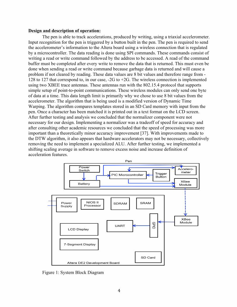
BOM: Table 1: BOM
Part Supplier Unit Cost
Quantity
Important Specs
Description Datasheet Links
Altera/Terasic DE2
development board
Altera http://www.altera.
com/
$269.00 1 - -
ftp.altera.com/up/pub/Webdocs/DE2_UserManual.pdf
Accelerometer Sparkfun https://www.sparkfun.com
/
$16.54 2 -SPI Digital Interface
- 3-axis ±2, ±4, ±8
400Hz
Triple Axis
Accelerometer
Breakout – ADXL362
https://www.sparkfun.com/products/11446
Coin
Battery –
20mm (CR2032)
Sparkfun https://www.sparkfun.com
/
$2.16 6 3V 20x3.2mm 250mAh coin cell batteries
Coin Cell Battery – 20mm (CR2032) PRT-00338
https://www.sparkfun.com/products/338
Battery Holder Sparkfun https://www.sparkfun.com
/
$1.38 2 - 20mm Coin Cell Battery
Holder
https://www.sparkfun.com/products/8822
LED Tactile Switch
Sparkfun/Lab
https://www.sparkfun.com
/
$2.16 2 - Tactile Switch for
turning on/off the
pen
https://www.sparkfun.com/products/10443

6
PIC16F873A Microcontrolle
r
Mouser Electroni
cs http://ca.mouser.c
om/
$6.06 2 - PIC16F873A
Microcontroller for pen
data transferring
http://ca.mouser.com/ProductDetail/Microchip-
Technology/PIC16F873A-I-
SP/?qs=0R2K/H4DmMPxNriMaf52iA==
XBee 1mW Trace Antenna
Sparkfun https://www.sparkfun.com
/
$25.39 2 3.3V @ 50mA
250kbps Max data
rate 1mW output
(+0dBm) 300ft
(100m) range
2.4GHz XBee
module
https://www.sparkfun.com/products/11215
Breakout Board for
XBee Module
Sparkfun https://www.sparkfun.com
/
$3.26 2 - This board breaks out all 20 pins
of the XBee to a 0.1" standard
spacing dual row header
https://www.sparkfun.com/products/8276
¾” Nylon Standoffs C/W
Screws
Toolbox $0.50 4 ¾” screws, plastic
standoffs
Used to hold the
punchboard off the table
N/A
40 Pin Ribbon Cable
Toolbox $15.00 1 40 pins Used to connect the
XBee module to the DE2
Altera Board
https://eclass.srv.ualberta.ca/pluginfile.php/991173/mod_resource/content/1/DE
2.qsf.txt
Crystal Clock Rick’s $0.17 1 3.6864 Hz, Used with http://www.datasheetarchi

7
Oscillator Store/FoxElectro
nics http://www.foxonline.com/
small the PIC to generate a
clock frequency
ve.com/dlmain/Datasheets-11/DSA-219975.pdf
Ceramic Capacitors
Rick’s Store
$0.25 2 15pF Used in conjunction
with the crystal
oscillator
N/A
PIC16f873A Headers
Rick’s Store
$0.99 1 28 Pin header
Used for placing the PIC pins
into
N/A
Resistor Lab $0.01 1 62.5 kohm (Blue, Red, Red, Gold)
Used with the tactile switch to
pull signal from high to
low
N/A
Power Brick Toolbox $10.00 1 9V DC 1.3A
Powering the DE2
Altera Board
Punchboard Toolbox $8.00 1 0.1mm spacing
Used for holding
components in place and for wiring
N/A
Tactile Switch Rick’s Store
$0.15 1 Push for on
Used for sending data from the pen to the XBee
N/A
Cardboard tube for pen
Kyle’s Stock
$0.25 1 Sturdy, Large
enough for components
Encases the pen’s
components
N/A

8
XBee XBIB-U-DEV Board
Nancy/ DigiKey http://www.digikey.ca/prod
uct-detail/en/XBIB-U-DEV/602
-1407-ND/3482
650
$83.00 1 2.4 GHz USB http://ftp1.digi.com/support/documentation/xbibudev
_referenceguide.pdf
Total per one quantity
$440.73
Overall Cost
$511.61
Reusable Design Units: Reusable Design: Bytefish Dynamic Time Warping quick implementation - used for the DTW module, a basic implementation of the DTW algorithm. We are using the source code as a starting point for testing and implementing our own DTW algorithm [31]. We will be reusing the 2010w project-interfacing component for XBee communication components by Anita Has and Kristina Suen [36]. We will also be using their appnote that they had created for setting up two Xbees to communicate with each other [28]. PIC UART Library – we are using this UART library that was made for PIC16F77A and modifying it to our specifications for the PIC16F873A [38].
For testing the UART on the Altera DE2 FPGA, an appnote on interfacing with RS232 UART was used. This was adapted to work via GPIO pins rather than through the RS232 port. It made a basic testing program for sending and receiving characters. [35]

9
Datasheet: All IO Signals:
Figure 2 of back side of accelerometer [1] Table 2: Accelerometer IO [2]
I/O Connection Pin Number Description Type
VDD 1 I/O Supply Voltage for Digital I/O In
GND 2 Ground. This pin must be grounded. Out
INT1 3 Interrupt 1 Output. INT1 also serves as an input for external clocking
In
INT 2 4 Interrupt 2 Output. INT2 also serves as an input for synchronized sampling.
In
CS 5 Chip Select, Active Low. Must be low during SPI communications
In
MISO 6 Master Input, Slave Output. SPI serial data output Out
MOSI 7 Master Output, Slave Input. SPI serial data input. In
SCLK 8 SPI Communications Clock In

10
Figure 3: XBee RF Module [3] Table 3: XBee RF Module
I/O Connection Pin Number Description Type
VCC 1 Power Supply -
DOUT 2 UART Data Out Out
DIN/CONFIG’ 3 UART Data In In
GND 10 Ground -
Fig 4: PIC 16F973A Microcontroller [41]

11
Table 4: PIC 16F973A Microcontroller
I/O Connection Pin Number
Description Type
MCLR/Vpp MCLR 1 (1)Master Clear or (2)Programming Voltage
(1)In or (2)Out
RA5/AN4/SS/C2OUT 7 SPI Slave Select Out
Vss 8 Ground Reference for logic and I/O pins -
OSC1/CLKI 9 Oscillator crystal or external clock input In
OSC2/CLKO 10 Oscillator crystal or clock output Out
RC3/SCK/SCL 14 Synchronous serial clock input/output for SPI mode
In/Out
RC4/SDI/SDA 15 USART asynchronous receive In
RC5/SDO 16 SPI data out Out
RC6/TX/CK 17 USART asynchronous transmit Out
RC7/RX/DT 18 USART asynchronous receive In
Vss 19 Ground reference for logic and I/O pins -
VDD 20 Positive supply for logic and I/O pins -
RB0/INT 21 Digital I/O In/Out

12
Table 5: Accelerometer Pen
Operating Range Consumption
Voltage 2.4V - 3.3V 0.4V
Current 120mA - 150mA 50mA
Power 288mW - 495mW 20mW Table 6: Xbee (on DE2)
Operating Range Consumption
Voltage 2.4V - 3.3V 0.4V
Current 120mA - 150mA 50mA
Power 288mW - 495mW 20mW
Table 7: Altera DE2
Operating Range Consumption
Voltage 125V 125V
Current 15A 15A
Power 1.875 kW 1.875 kW Power = Voltage x Current = V X I

13
Background Reading: Most of our articles that we found for our project are based off the IEEE site. We also read some published papers from various sources. [20] Provided general information regarding DTW algorithm and helped us identify a pattern recognition algorithm to use. [10] Provided information on a similar project using an accelerometer in a Wii mote. Also compared different pattern recognition algorithms such as the Hidden Markov Model and Dynamic Time Warping. [21][22][38] Provided comparisons between different implementations of the DTW algorithm including FastDTW, SparseDTW, and the Sakoe-Chiba band as approximation solutions to calculating DTW faster or reducing space cost required for the algorithm. Comparisons of these algorithms helped us in the development and implementation of our own DTW algorithm. The current implementation of the DTW algorithm uses a Sakoe-Chiba band approximation. To match characters based on acceleration patterns, we use an algorithm called Dynamic Time Warping (DTW). Dynamic Time Warping is a general pattern-matching algorithm that has been used successfully in the past in other applications such as voice or image recognition. The idea behind DTW is to take two acceleration patterns, one from the input of the pen and one from a template we are trying to match, and find their similarity using Euclidean distance. We can do this by constructing a matrix where the width and length of the matrix are the size of each acceleration pattern respectively. In the first cell of the matrix we calculate the Euclidean distance from one point in one acceleration pattern to the corresponding point in the other pattern. The lower the distance the closer the two patterns match. We then find Euclidean distances for adjacent cells and add the minimum distance cell to our score. We continue this process using dynamic programming to find an optimal path in the matrix as determined by the algorithm. When the algorithm reaches the end of the matrix, the total summation gives us our score for the comparison. We repeat this process for all of our templates and the lowest total score will tell us which pattern our input matches. The modified version of our implementation of DTW follows a Sakoe-Chiba band optimization. Essentially this modification ignores the two corners of the matrix to form a band, as the optimal path rarely traverses to the corners of the matrix.

14
Software Design: As stated in the design and description overview of our project, we have decided to remove the acceleration normalizer of our design. The main components of the software design of our project now consist of two major components, the calibration software, and the pattern matching algorithm. Data received from the accelerometer arrive on the UART in 8 byte pairs for x and y data.
The calibration software is a basic test to ensure that the pen is functionally operational as well as giving us the ability to store templates for pattern matching. The basic tasks involved will read from UART buffer, and store configurations onto an SD Card. To increase accuracy of templates, we store four templates per one character pattern. On boot, the templates are read from the SD Card, preprocessed and then loaded into SRAM. For the pattern matching mode, there are similar tasks to read input from the UART, preprocess and store the data into SRAM. Preprocessing data for templates and user input
consists of a shifting pseudo-average that scales the numbers for precision in later processing and helps to smooth out excess noise. The shifting average takes the sum of five numbers. Two values before the data point and two values after the data point are added together, the value is then multiplied by two. Division is not used in order to increase processing speed and to make peaks more defined. The processed data points are now more consistent, and scaled approximately by a factor of ten. To accommodate the increased number size and the calculations required by our pattern matching algorithm, we store the data values in SRAM as 32 bit signed values.
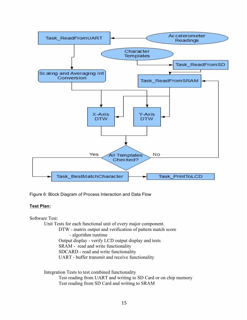
Character reading data from the UART will enter into a secondary buffer that allows the UART buffer to empty. The secondary buffer can store up to ten characters while a character is being processed by the DTW algorithm. When the DTW task has resources available to process a character, the data is pulled from the secondary buffer. This data will be passed to a template matching task. The template matching task will spawn multiple tasks running the DTW algorithm for x, y orientations. The tasks running the DTW algorithm will also have input from the templates stored in SRAM. The DTW task will output a score for the current input with a lower score being better. The template matching task will calculate a total score by adding the score from the x and y DTW comparisons as well as a value based on Pythagorean theorem to account for pen rotation. The DTW algorithm is run four times through four different groups of templates and for both x and y orientations. The total score for each template is added up by the template matching task. In total the DTW algorithm is run thirty-two times for one character. After the total score is found for each template, the template with the lowest score is selected as the best match and passed along to a display task. The DTW algorithm itself is a variant on the original design that uses the Sakoe-Chiba band approximation [38]. The band approximation relies on the assumption that the ideal warping path is situated near the center of the diagonal of the matrix, and as such the algorithm ignores the outer edges of the matrix. This assumption has been shown to hold true for most time series patterns produced from analog input. More information regarding the DTW algorithm can be found under the Background Readings section.
15
Figure 6: Block Diagram of Process Interaction and Data Flow Test Plan: Software Test: Unit Tests for each functional unit of every major component.
DTW - matrix output and verification of pattern match score - algorithm runtime Output display - verify LCD output display and tests SRAM - read and write functionality SDCARD - read and write functionality UART - buffer transmit and receive functionality
Integration Tests to test combined functionality Test reading from UART and writing to SD Card or on chip memory Test reading from SD Card and writing to SRAM
16
Test DTW algorithm with input from SRAM or on chip memory Test template matching behavior with DTW algorithm output System Testing to test the completed design
Rigorous testing of different shapes and calibrations to reach the highest amount of accuracy possible.
Memory Leaks - We can let the Accelerometer pen constantly send data to the XBee Module to identify memory leaks or possible buffer overflows.
Accelerometer output testing - verify that output from the accelerometer can be adequately handled by FIFO’s.
Hardware Test:
Accelerometer - We can power up the accelerometer and hook it up to the oscilloscope to check the output waveforms and use the embedded self-test. Hook up the accelerometer to the PIC and see if data is being received. Coded PIC to poll x, y, and z data from accelerometer and send through XBee using UART.
Flash - Reload the lab 2 that we completed onto flash to initially see if the flash is working properly. Then, redo the lab 2 with our non-volatile program to check if the operation matches the operation of lab 2.
LCD Module - Load matching program onto the board and test if we can print to the LCD screen. Print the name of the shape which was closely matched.
XBEE Wireless Module - Using 2 XBEE modules and the X-CTU program, we will test the communication and range of both the modules. We will also test the transmitting and receiving function of both modules.
Data Trigger Switch - When the switch is pressed and held, the PIC should send the data from the accelerometer to the XBEE module to transmit to the other XBee on the Altera board to process the data. For initial tests, the stat trigger would just tell the PIC to light up an LED.
Coin Cell Battery - Using the voltmeter, we can test if the coin cell battery displays the correct voltage. Also, use the coin cell battery in a mock up circuit to see how long it will last.

17
SD Card – Load character test templates and read from SD Card. Ejected SD Card from DE2 board and inserted it into a computer to see if there is anything written on there after calibration. PIC16F873A – Write some code to turn on and off an LED attached to RB0 pin of the PIC. Also, continuously send data through the RC6/TX pin of the PIC and see if data is being transmitted. We can do this by hooking up the oscilloscope to see any changes. Also, hook up the XBee to the PIC and use the X-CTU program to see if the other XBee is reading the correct data. Probe selected pins to see changes on oscilloscope if data is being sent or received.
Results of experiments and characterization:
The following tests were run under the ECE492 lab computers running an i7 3.4GHz processor. We expect, based on estimates of MIPS Dhrystone testing available online, that the NiosII processor to be approximately 100 times slower than the current lab configuration. Correctness and speed was tested using test_dtw_algorithm.cpp. Using sample input generated from matlab for two vectors of 400 data points corresponding to 200Hz we tested the DTW algorithm. The average runtime on the lab computers was 0.171s or 171clock ticks. The algorithm behaved as expected with an optimal path distance of identical vectors equal to zero. Vectors with different values varied optimal path distance by up to 500 according to the values tested. The larger the range in optimal path distance, the better we can determine the accuracy in pattern matching.
We next implemented a scaled integer version of the DTW algorithm using a similar configuration as above. test_dtw_scaled_int.cpp showed a varied optimal path distance by up to 50000 using a pseudo two decimal precision with scaled integers, and ran in 0.091s. We realized that just using scaled integers would not be enough to reach near real-time processing so we next implemented a Sakoe-Chiba band variation of the DTW algorithm test. This implementation test_dtw_band.cpp, greatly reduced the runtime to 0.009s with similar varied optimal path distance of up to 50000. The band size constraint could also be modified to increase accuracy at the cost of speed or vice versa. Moving to the DE2 board, unit and integration testing proceeded relatively smoothly according to schedule. After getting data from the accelerometer we began system testing and debugging. The DTW algorithm was adapted to a C implementation. Initial tests with the accelerometer identified major bugs regarding both input from the accelerometer and with data processing. The pattern matching algorithm ran slower than expected and was outputting values that were overflowing our expected 32 bit values. To increase speed of processing we clocked the Nios II processor to 80MHz and implemented the fast version of the processor. After testing with real data we also decided to reduce expected worst case data size to 200 points instead of 400 points for one coordinate. This corresponds to the expectation that we found to be true that it would take under a second at 200Hz for someone finish writing a character.
To fix the output value overflow, we debugged portions of code and examined memory contents. We were experiencing some floating input on the PIC, which caused the PIC to freeze when it was powered on and not function until you move your hand close to the MCLR pin on
18
the PIC. To fix our floating reset signal on the PIC, we had to tie the MCLR pin to VDD. After making modifications to the code and accelerometer pen we were able to fix some of our overflow issues. After closer examination of the SRAM memory we were able to determine that the processor was not synchronized correctly with SRAM and was not storing the values we expected at the time that the SRAM was read. This problem resulted partly because the Altera university program core for SRAM needed more cycles to move 32 bit data than 16 or 8 bit values and the 80MHz clock was not matching with the time required to write to SRAM. To solve this issue we reverted back to a 50MHz clock and a Nios II processor set on standard.
While doing system testing we began to realize that the data received from the
accelerometer varied significantly from person to person and even from the same person writing the same shape. At that time we still had the intention of testing character patterns for numbers 0 through 9. Based on the results and our expectations for the project, we decided to scale back our characters and rethink how we were processing our characters as the hardware would not be sufficient to accurately process numbers within a reasonable processing time. There are a number of reasons for why we came to this conclusion. Firstly due to the aforementioned problems we would be unlikely unable to run more than 20 templates through DTW using a standard Nios II processor without sacrificing accuracy or having unacceptable runtimes. We would also be unable to improve accuracy of data input by increasing accelerometer frequency due to SRAM size. The SRAM size was limiting the majority of memory allocation had to be done on SRAM as on-chip memory was not large enough for the DTW matrix. The DTW matrix required a 200x200 matrix of 32 bit values for both x and y orientations resulting in approximately 320kB, and with a max size of 512kB of SRAM, 64 bit values would not be viable. After reaching these conclusions we focused on four shapes. These shapes we drew were done so that the acceleration profiles would be as different from one another as possible. We attempted to improve the quality of our templates by storing four calibrations for each template shape. To get rid of excess noise we implemented a shifting pseudo shifting average that incorporated our previous scaled int conversion. We also decided to focus on user dependent data to match our patterns as consistently as possible. After implementing these changes we found we were able to achieve on average a 75% accuracy rate running in 6 secs. We found our running time increased significantly after flashing our software to the board and had an average running time of 8-12 secs. Please see appendix for visual plots received data.
For testing the accelerometer we had to somewhat assume the PIC microcontroller was
working properly. We were somewhat able to check the operation of the PIC by attaching an oscilloscope and probing the output pins of the microcontroller. These pins included serial clock and data out to the accelerometer. The accelerometer data was tested in a very basic way by transmitting the data across the XBees and just checking to make sure the values changed as the accelerometer was tilted. The data was then checked to be semi-accurate by making sure zeroes were read when the axis being checked was not tilted at all and making sure ~69’s (1G) were read when the axis was tilted 90°. This was all found to be quite accurate.
The trigger switch was tested by programming the PIC to set an output to 1 if the button
was pressed. This output would be connected to an LED which would light up when given voltage. This was a quick way to test the logic for when the button was pressed.

19
Since the LCD screen was a small implementation that was done in lab1, we tested it alongside the SD card. They were tested by displaying a “Write template <#>” and then getting the person to press the trigger button so that data is written. We would make sure the accelerometer was in a position in which the values read would be known. The SD card was read in and made sure to have the values we expected.
The coin cell battery was tested by hooking it up to power our circuit and simply seeing how long it would run. The battery would drop to ~2.6V initially due to voltage drop in the components. /it was also found that despite expectations, the voltage would drop to around 2V after about 10-15 minutes. This voltage was no longer high enough to properly power our XBee and therefore some data would not be transmitted. We decided not to use the batteries for this reason. Safety:
This project incorporates external components into a pen device. Safety considerations include grounding and shielding the pen and electrical components properly to reduce risk of electric shock. This shock is a very low risk concern due to the low levels of voltage used. Some components might be fried due to overvoltage. Checking all the required voltages of each device and the power source can mitigate this danger. Environmental Impact: Our project contains no hazardous substances. Accelerometer -- RoHS Compliant Lithium Coin Cell Battery -- No special disposal. Not considered a hazardous waste unless it is fully charged or only possibly discharged. Coin Cell Battery Holder -- RoHS Compliant LED Tactile Switch -- no important environmental effects XBee S1 Module -- RoHS Compliant XBee Breakout Board -- RoHS Compliant PIC16F873A – RoHS Compliant Tactile Switch -- RoHS Compliant Crystal Oscillator Clock -- Very small traces of lead. Not RoHS Compliant. There is an RoHS Compliant alternative.
20
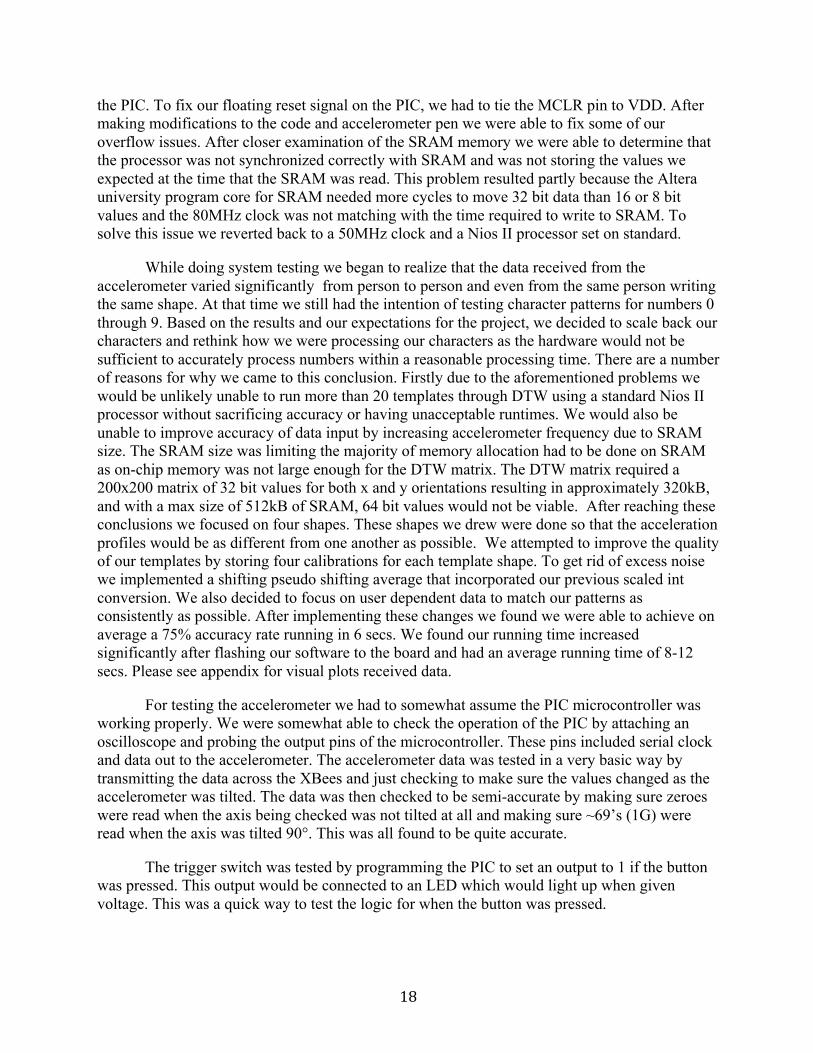
Sustainability: Table 8: Device Specs
Device Current (Sleep/Idle)
Current (Awake) Voltage Active Power
Idle Power
Duty Cycle Active/Idle
AVG Power
Consumption
Cost
Accelerometer
10 nA 1.8 uA @100Hz 3.0 uA @400Hz
3.3V 9.9uW 3nW 66.7% 33.3%
6.61kW 57.94MWh
$50.41/year
XBEE Module
50 mA (Receive)
45 mA (Transmit)
50 mA (Receive)
3.3V 0.1485W 0.1815W
0.1815W 66.7% 33.3%
1.64W 2.00W
14.4kWh 17.5kWh
$12.51/year
$15.25/year
LED Tactile Switch
N/A 50 mA 3.3V 0.165W N/A 66.7% 33.3%
N/A N/A N/A
PIC16F873A
Microcontroller
110mA 120mA 3.3V 0.396W 0.363W 66.7% 33.3%
2.17W 19.0kWh $16.55/year
Power Formula Calculations: Active Power = Idle Power = V x I Duty Cycle Active = 8h awake / 12h period = 66.7% Duty Cycle Idle = 4h idle / 12h period = 33.3% AVG Power = [Active Power * Active Duty Cycle] / [Idle Power * Idle Duty Cycle] Power Consumption per Hour = Power x (24h/day) x (365.25 day/year) Cost = Power Consumption per Hour x (8.7cents per kWh) Optional integrated circuit design proposal: -None proposed. Quick Start Manual: Hardware Setup:
- Connect DC voltage supply to the appropriate pins on the pen. The positive rail on the pen can be located by checking which battery holder pin the red wires all connect to. The negative rail is connected with white wires. The voltage supply must be set to 3.0V. The

21
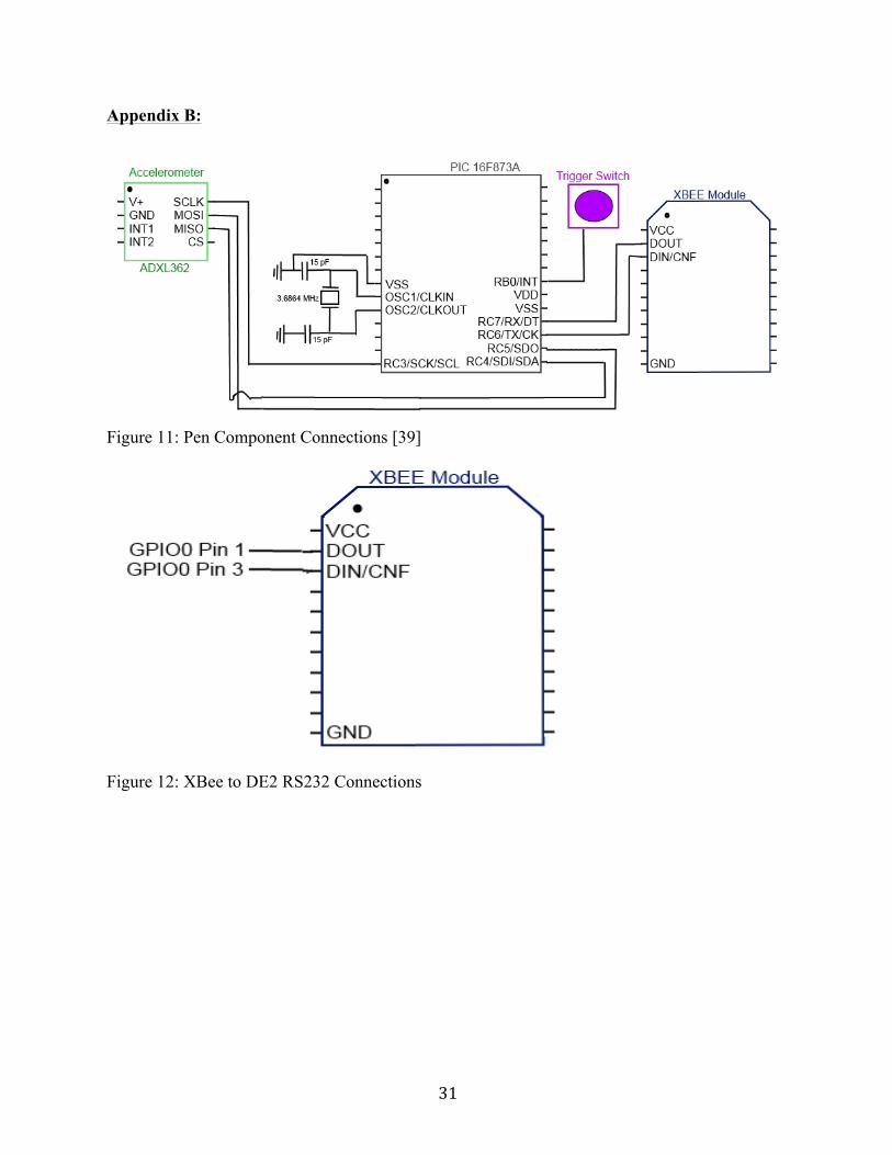
current needs to be set at 150mA. The voltage supply must also run to the power (pin 1) and ground wire (pin 10) of the XBee module on the Altera side. These settings can be the same as the pen side. - Connect the DOUT pin of the XBee (pin 2) to pin 1 of GPIO 0 on the Altera. Connect the DIN pin of the XBee (pin 3) to pin 3 of the GPIO 0. These DOUT pin should be directly above the DIN pin.
Software Setup: - Open accelerometer_pen.qsf to open the Quartus project.
- Program the FPGA with either the .SOF file, for flash programming, or the .POF file, for which the program will be run from Eclipse.
Running the Program - Switch 0 decides the mode. If the switch is in the down position, the program will be in calibration mode. If the switch is toggled up, it will be in processing mode. - For flash, just program the accelerometer_pen50sflash to the board. - For just running from Eclipse, open the accelerometer_pen50s program and corresponding bsp. Run the accelerometer_pen50s.c file to begin. - To write a character, hold the button on the pen immediately upon starting the character and release the button as close to the end of the character as possible. Calibration Mode - Before calibrating, the SD card must be taken and cleared so that the only thing that remains is an empty FILE.txt. - For calibration, the program will cycle through and read in 16 templates (4 for each character). The LCD screen will prompt you for each written character. Templates 0-3, 4-7, 8-11, and 12-15 should be circle, triangle, checkmark, and line respectively. These are shown in Appendix. - When done calibrating, toggle the switch to the up position. For flash, power cycle the board to restart in processing mode. If running from Eclipse, just rerun the program. Processing Mode - If the switch is toggled up, it will be in processing mode where it is ready to accept a new character and will compare it to the templates.
- Wait until the LCD screen diplays “Ready to read”. - Write your character and then the word “Processing…” should appear. - Wait until the best match shows up like this “match <SHAPE HERE>”.
- The shape will be displayed depending on the template group as listed in the Calibration mode and in Appendix B Figure 17. At this point, the program is now ready to receive the next character.

22
Future work: - Ability to recognize numbers - Extra button to change pen functionality to perform basic arithmetic - Incorporate functionality where users can write on any surface at any time by incorporating a gyroscope - Ability to recognize alphabets (in future - handwriting) - Design a GUI for character display on the computer - Sensor activated without use of a button trigger (pressure, proximity, or voice sensors) - Incorporate Bluetooth and integrate this new design so that users can connect the pen to their smartphones and generate outputs to an app - Multiple user interactions - Accuracy and speed refinement Appendix A: Hyperlinked Parts List
Accelerometer https://www.sparkfun.com/products/11446
Coin Cell Battery 20mm (CR2032) https://www.sparkfun.com/products/338
Battery Holder https://www.sparkfun.com/products/8822
Tactile Switch https://www.sparkfun.com/products/10443
XBee 1mW Trace Antenna https://www.sparkfun.com/products/11215
XBee Module Breakout Board https://www.sparkfun.com/products/8276
PIC16F873A Microcontroller http://ca.mouser.com/ProductDetail/Microchip-Technology/PIC16F873A-I-
SP/?qs=0R2K/H4DmMPxNriMaf52iA==

23
References: - Datasheets: [1] -- Sparkfun. ADXL362 Breakout Photo. Accessed: Jan 19, 2014, Available: https://dlnmh9ip6v2uc.cloudfront.net//images/products/1/1/4/4/6/11446-03a.jpg [2] -- Analog Devices (2012, Sept.) ADXL362 Data Sheet. Accessed: Jan. 18, 2014. [Online] Available: http://dlnmh9ip6v2uc.cloudfront.net/datasheets/BreakoutBoards/ADXL362.pdf Datasheet [3] – Xbee/Xbee-PRO RF Module (2009, Sept.) Xbee Data Sheet. Accessed: Jan. 30, 2014. [Online] Available: https://www.sparkfun.com/datasheets/Wireless/Zigbee/XBee-Datasheet.pdf Datasheet [4] – Pololu, Step-Up Voltage Regulator Part. Accessed: Jan. 18, 2014. Available: http://www.pololu.com/product/2561 - Papers on Accelerometer Pen: [5] -- Aatish Bhatia, Workshop 3. Rutgers Univ. New Brunswick, NJ. [Online] Available: http://physics.rutgers.edu/~aatish/teach/srr/workshop3.pdf [6] -- ST Microelectronics (2010, Apr), AN3182 Application note: Tilt measurement using a low-g 3-axis accelerometer [Online], Available: http://www.st.com/web/en/resource/technical/document/application_note/CD00268887.pdf [7] -- J. Wang and F. Chuang. (2012, July). “An Accelerometer-Based Digital Pen With a Trajectory Recognition Algorithm for Handwritten Digit and Gesture Recognition”. IEEE Trans. Ind. Electron., Vol. 59, No. 7, pp. 2998-3007 [Online]. Available: http://ieeexplore.ieee.org/stamp/stamp.jsp?tp=&arnumber=6020787 [8] -- S. Zhang, C. Yuan, Y. Zhang. Handwritten Character Recognition Using Orientation Quantization Based on 3D Accelerometer. Tsinghua Univ. and Harbin Institute of Tech. Shenzhen, China. [Online] Available: http://redwood.cs.ttu.edu/~shiqizha/papers/hucubis_2008.pdf [9] -- J. Wang, Y. Hsu, C. Chu. Online Handwriting Recognition Using an Accelerometer-Based Pen Device. presented at 2nd International Conference on Advances in Computer Science and Engineering. [Online]. Avaliable: www.atlantis-press.com/php/download_paper.php?id=6908 - Dynamic Time Warping:

24
[10] -- Ahmad Akl, “A Novel Accelerometer-based Gesture Recognition System,” M.S. thesis, Elec. and Comp. Eng., Univ. of Toronto, Toronto, ON, 2010. [Online]. Available: https://tspace.library.utoronto.ca/bitstream/1807/25403/3/Akl_Ahmad_201011_MASc_thesis.pdf - Accelerometer/Gyro Tutorials/Info: [11] -- Instructables, Accelerometer & Gyro Tutorial, Accessed: Jan. 17, 2014. Available: http://www.instructables.com/id/Accelerometer-Gyro-Tutorial/?ALLSTEPS [12] -- Texas Instruments, Accelerometers and How They Work, Accessed: Jan. 17, 2014. Available: http://www2.usfirst.org/2005comp/Manuals/Acceler1.pdf - Sites for Products: [13] -- Sparkfun. Accelerometer Part. Accessed: Jan. 15, 2014. Available: https://www.sparkfun.com/products/11446 [14] -- Sparkfun. Tactile Switch Part. Accessed: Jan. 19, 2014. Available: https://www.sparkfun.com/products/10443 [15] -- Sparkfun. Coin Cell Battery Part. Accessed: Jan. 18, 2014. Available: https://www.sparkfun.com/products/338 [16] -- Sparkfun. Step-up Voltage Regulator Part. Accessed: Jan. 18, 2014. Available: http://www.pololu.com/product/2561 [17] -- Sparkfun. XBee Trace Antenna Part. Accessed: Jan. 28, 2014. Available: https://www.sparkfun.com/products/11215 - Letters Stroke Analysis: [18] – van Galen, G.P., Meulenbroek, R.G.J., & Hylkema, H., Graphonomics: Contemporary Research in Handwriting, Amserdam, Netherlands. Accessed: Jan. 20, 2014. [Online] Available: http://books.google.ca/books?hl=en&lr=&id=AOKFfnzRtEEC&oi=fnd&pg=PA33&dq=The+influence+of+changes+in+the+effector+coordinate+system+on+hand-++writing+movements+in+graphonomics&ots=iB-Ee_AwpT&sig=xo-A3yEmI0wpDJk3bMXaZsLmhTw#v=onepage&q&f=false - Altera DE2 Board: [19] -- Altera. DE2 Layout Image. Accessed: Jan. 16, 2014. Available: http://www.esng.dibe.unige.it/deeds/LearningMaterials/LM/Tutorials/DE2/DE2_layout_1000m.JPG - DTW Algorithm - Jan. 28

25
[20] -- Gerrit Niezen and Gerhard P. Hancke (2009, Sept.). Evaluating and optimizing accelerometer-based gesture recognition techniques for mobile devices. University of Pretoria. Pretoria, South Africa. [Online] Available: http://www.academia.edu/840135/Evaluating_and_optimising_accelerometer-based_gesture_recognition_techniques_for_mobile_devices - New DTW - Jan.28 [21] -- G. Al-Naymat, S. Chawla, J. Taheri. (2009, Dec.) “SparseDTW: A Novel Approach to Speed Up Dynamic Time Warping”. The 2009 Australasian Data Mining, Vol. 101. Melbourne, Australia, ACM Digital Libraru, pp. 117-127. [Online]. Available: http://arxiv.org/abs/1201.2969 [22] -- Google. FastDTW. Accessed: Jan. 29, 2014. Available: http://code.google.com/p/fastdtw/ - XBEE Testing - Jan.28 [23] -- M. Hebel, G. Bricker (2010), Getting Started with XBee RF Modules. Parallax Inc.[Online]. Available: http://www.parallax.com/sites/default/files/downloads/122-32450-XBeeTutorial-v1.0.1.pdf - ALU Testing - Jan.28 [24] -- J. Bakos. FPGA Verification of ALU. Univ. of South Carolina. [Online] Available: http://www.cse.sc.edu/~jbakos/611/tutorials/tutorial14.pdf - Signal Filter - Jan. 28 [25] -- J. Kong Jak Kan., “FIR DIGITAL FILTER ON FPGA FOR ECG SIGNAL PROCESSING,” M.S. thesis, Dept. Elect. Eng., Universiti Teknologi Malaysia, Kuala Lumpar, Jun. 2012. Accessed: Jan. 21, 2014. [Online] Available: http://portal.fke.utm.my/fkelibrary/files/johnnykongjakkan/2012/207_JOHNNYKONGJAKKAN2012.pdf - Reused Source Code - Jan.28 [26] -- Zbigniew Siciarz. Open Source DSP library for C++. Accessed: Jan 27, 2014. Available: http://aquila-dsp.org/about/ - Multiplier VHDL code - Jan.28 [27] -- Giovanni DíAliesio. “8-by-8 Bit Shift/Add Multiplier”. Dept. Elec. Comp. Eng., Concordia Univ., Montreal, QC. Dec. 2003. [Online] Available: http://users.encs.concordia.ca/~asim/COEN_6501/project_Giovanni_D%27Aliesio.pdf - XBEE Modules - Jan. 30 [28] -- University of Alberta (2010, Apr), Application note: XBEE Wireless Communication

26
[Online], Available: http://www.ece.ualberta.ca/~elliott/ece492/appnotes/2010w/XBee_Wireless_Communication/ - Project that uses XBEE modules - Jan. 30 [29] -- Anita Has and Kristina Suen, “ Smart-AKK,” Dept. Elec. Comp. Eng., University of Alberta, , Edmonton, AB. Apr. 2010. [Online] Available: http://www.ece.ualberta.ca/~elliott/ece492/projects/2010w/g2_keys/g2%20FINAL%20REPORT.pdf [30] -- MeshNetics (2008, Mar), AN-481 Application note: Battery Lifetime Estimation [Online], Available: http://www2.ee.ic.ac.uk/t.clarke/projects/Resources/ZDK_v2.0_Complete/Documentation/Application%20Notes/AN-481~12-(Battery%20Lifetime%20Estimation).pdf - Dynamic Time Warping source code - Jan 31 [31] -- Philip Wagner (2010, Aug), Dynamic Time Warping [Online], Available: http://bytefish.de/blog/dynamic_time_warping/ [32] -- Battery Compartment and Device Design Considerations, Energizer Holdings, Inc., St. Louis, MO [Online], Available: http://data.energizer.com/design_hints/catalog/designhints_catalog.pdf [33] -- Sparkfun. XBee Module Breakout Board. Accessed: Jan. 28, 2014. Available: https://www.sparkfun.com/products/8276 [34] -- Mouser Electronics. PIC16F873A Microcontroller Part. Accessed: Feb. 13, 2014. Available: https://github.com/dleclerc/Battleship_EECE381/blob/master/sd_card.c http://robkaram.com/simple-sd-card-interfacing/ [35] -- K. Lau. (2014, Feb), Application note: Tutorial of Interfacing with RS232 UART [Online], Dept. of Elec. and Comp. Eng., University of Alberta, Edmonton, AB. Available [Not Public]: https://www.ualberta.ca/~delliott/local/ece492/appnotes/2014w/G3_UART_Interface/G3_UART_Appnote.pdf [36] -- O Henniger (2007, Apr) The Effect of Time Normalization on the Accuracy of Dynamic Time Warping [Online], Available: http://www.seceng.informatik.tu-darmstadt.de/assets/mueller/btas07.pdf

27
[37] -- H Sakoe , S Chiba (1987, Feb) Dynamic programming algorithm optimization for spoken word recognition [Online], Available: http://ieeexplore.ieee.org/xpl/login.jsp?tp=&arnumber=1163055&url=http%3A%2F%2Fieeexplore.ieee.org%2Fxpls%2Fabs_all.jsp%3Farnumber%3D1163055 [38] – PIC UART Library, Accessed: Feb. 27, 2014. [Online], Available: http://extremeelectronics.co.in/pic16f877a-tutorials/usart-library-for-pic-setup-on-mplab-x-ide/ [39] – Crystal Oscillator Connection, Accessed: Mar. 2, 2014. [Online], Available: http://www.dreamincode.net/forums/topic/89581-pwmadc-codeschematicpic16f873a-working-in-sim-not-in-when-hooked-u/ [40] -- Altera. Computer Organization IP Cores [Online] Available: http://www.altera.com/education/univ/materials/comp_org/ip-cores/unv-ip-cores.html [41] -- Microchip (2003) PIC16F87XA Data Sheet. Accessed: Feb. 28, 2014. [Online] Available: http://ww1.microchip.com/downloads/en/DeviceDoc/39582b.pdf [42] – XBee Radios (2011 Jul.) Basic point-2-point communication, Accessed: Feb. 28, 2014. [Online], Available: http://www.ladyada.net/make/xbee/point2point.html [43] – Stack Exchange (2012 Nov.) How do you set the configuration bits for a PIC 16F1829 in MPLAB X, Accessed: Mar. 2, 2014. [Online], Available: http://electronics.stackexchange.com/questions/47040/how-do-you-set-the-configuration-bits-for-a-pic-16f1829-in-mplab-x [44] – MICROCHIP, MPLABX IDE, Accessed: Feb. 25, 2014. [Online], Available: https://www.microchip.com/pagehandler/en-us/family/mplabx/ [45] -- Digi, XBIB-U-DEV Reference Guide, Accessed: Feb. 14, 2014. [Online], Available: http://ftp1.digi.com/support/documentation/xbibudev_referenceguide.pdf [46] -- Fox Electronics, (2003) Standard Crystals. Accessed: Apr. 1, 2014. [Online], Available: http://www.datasheetarchive.com/dlmain/Datasheets-11/DSA-219975.pdf [47] -- nu32-PIC32 (2013 Oct.) SPI to ADXL362 Accelerometer, Accessed: Mar. 28, 2014. [Online], Available: https://code.google.com/p/nu32-pic32/wiki/12SPIadxl362 [48] -- electroSome (2012 May) Using Push Button Switch with PIC Microcontroller, Accessed: Apr. 1, 2014, [Online], Available: http://electrosome.com/push-button-switch-pic-microcontroller/

28
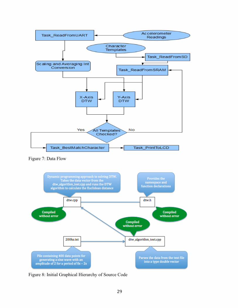
[49] -- Tsiporkova, E. “Dynamic Time Warping Algorithm for Gene Expression Time Series”, Accessed: Feb. 4, 2014, [Online], Available: www.psb.ugent.be/cbd/papers/gentxwarper/DTWAlgorithm.ppt Source code section: All source code compiled successfully and tested. Software configurations under test/software directory. Names match corresponding to Quartus folders under NiosII folder accelerometer_pen Contains initial test setup for accelerometer pen accelerometer_pen50s Contains final setup for accelerometer pen using sof file acclereomter_pen50sflash Contains final setup for accelerometer pen using pof file accelerometer_pen80 Contains setup for 80Mhz NiosII economy processor acclerometer_pen80f Contains setup for 80Mhz NiosII fast processor test_dtw_algorithm original C++ implementation derived from bytefish source test_dtw_band Sakoe-Chiba band variation test_dtw_scaled_int Scaled integer DTW variation test_isqrt Test for square root implementation speed test_new_dtw C implementation of DTW test_niosII_avalon_uart UART using avalon cores test_niosII_sdcard Basic SD Card read and write test test_niosII_sdcard_to_sram Integration test with SD Card and SRAM tset_niosII_sram Basic SRAM read and write test test_niosII_sram_dtw Integration test with SRAM to DTW test_niosII_uart Basic UART test test_niosII_uart_sdcard Integration test for UART to SDCARD Under the LED_PIC16F873A folders: PIC16F873A main.c Code for polling data from accelerometer and sending to XBee uasrt_pic16.c Contains UART functions for XBee uasrt_pic16.h Contains UART function declarations spi_pic16.c Contains accelerometer SPI initialization spi_pic16.h Contains SPI function declarations
29
Figure 7: Data Flow
Figure 8: Initial Graphical Hierarchy of Source Code

30
Figure 9: Pen Input Flow Diagram
Figure 10: Character Template Data Flow
31
Appendix B:
Figure 11: Pen Component Connections [39]
Figure 12: XBee to DE2 RS232 Connections

32
Figure 13: Block Diagram of Hardware
Figure 14: Two acceleration patterns after preprocessing of the same character in the X-axis

33
Figure 15: Acceleration patterns of multiple attempts of the same character in the X-axis
Figure 16: Scaled integer comparison (red) Vs. Scaled average (green)

34
Figure 17: Shape Templates