Embed Size (px)
Citation preview
Accelerator Test Facility
V. Yakimenko
DOE Annual HEP Program ReviewBrookhaven National Laboratory
April 27-28, 2005
2
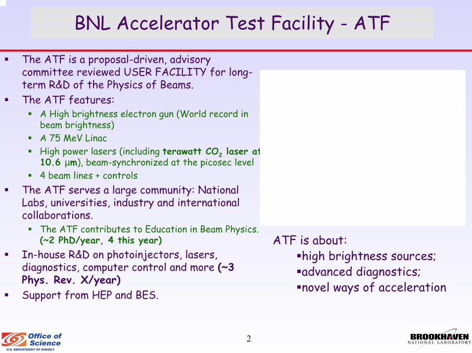
BNL Accelerator Test Facility - ATF
The ATF is a proposal-driven, advisory committee reviewed USER FACILITY for long-term R&D of the Physics of Beams.The ATF features:
A High brightness electron gun (World record in beam brightness)A 75 MeV LinacHigh power lasers (including terawatt CO2 laser at 10.6 µm), beam-synchronized at the picosec level4 beam lines + controls
The ATF serves a large community: National Labs, universities, industry and international collaborations.
The ATF contributes to Education in Beam Physics. (~2 PhD/year, 4 this year)
In-house R&D on photoinjectors, lasers, diagnostics, computer control and more (~3 Phys. Rev. X/year)Support from HEP and BES.
ATF is about: high brightness sources;advanced diagnostics; novel ways of acceleration

3
Recent Results (3 completed experiments, 2 PhD)
• Stimulated Dielectric Wakefield Accelerator. Omega-P Inc., Yale University, Columbia University. (Completed in July 2004; PhD: October 2004)
• Optical Diffraction-Transition Radiation Interferometry Diagnostics for Low Emittance Beams, TR Research Inc. U Maryland (Completed in January 2005)
• Nonlinear Compton Scattering, Tokyo Metropolitan U, Waseda U, KEK, Princeton U, UCLA (Completed in January 2005; PhD: March 2005) First experiment with new terawatt CO2 laser!
Filtered nonlinear Compton
Linear Compton

4
Optical Diffraction-Transition Radiation InterferometryA. Shkvarunets. R. Fiorito and P. O’Shea, Nuc. Instrum. and
Meth. B, 201, 153-169 (2003)
• Perforated first foil overcomes scattering limit of conventionalOTRI
• Extends OTRI diagnostics to low energy and/or low emittancebeams backward
5
ODTRI, 650 X 10 nm
Angle, 1/γ0.0 0.5 1.0 1.5 2.0
Inte
nsity
, OT
R u
nits
0.0
0.2
0.4
0.6
0.8
1.0
1.2
1.4
1.6
OTRI, 650 X 10 nm
Angle, 1/γ0.0 0.5 1.0 1.5 2.0
Inte
nsity
, OT
R u
nits
0.0
0.5
1.0
1.5
2.0
2.5
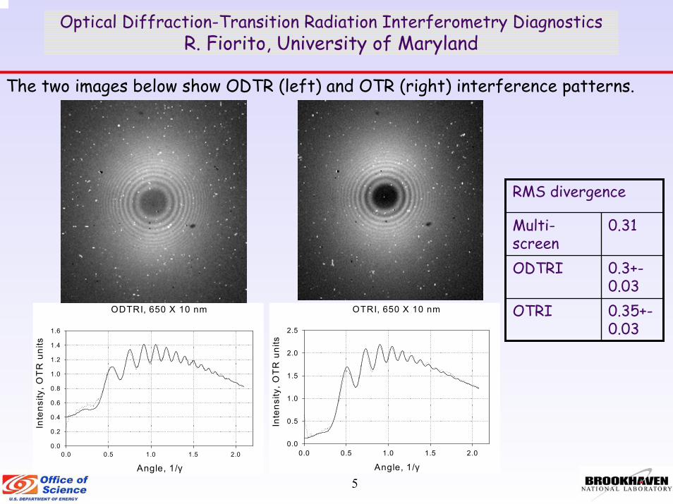
Optical Diffraction-Transition Radiation Interferometry DiagnosticsR. Fiorito, University of Maryland
The two images below show ODTR (left) and OTR (right) interference patterns.
0.35+-0.03
OTRI
0.3+-0.03
ODTRI
0.31Multi-screen
RMS divergence
6
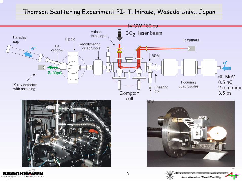
Thomson Scattering Experiment PI- T. Hirose, Waseda Univ., Japan

7
Compton Scattering of Picosecond Electron and CO2 Laser Beams
8
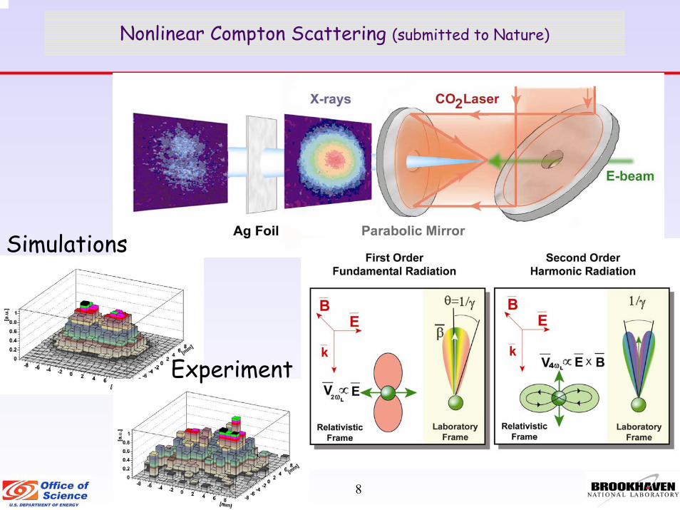
Nonlinear Compton Scattering (submitted to Nature)
Experiment
Simulations
9
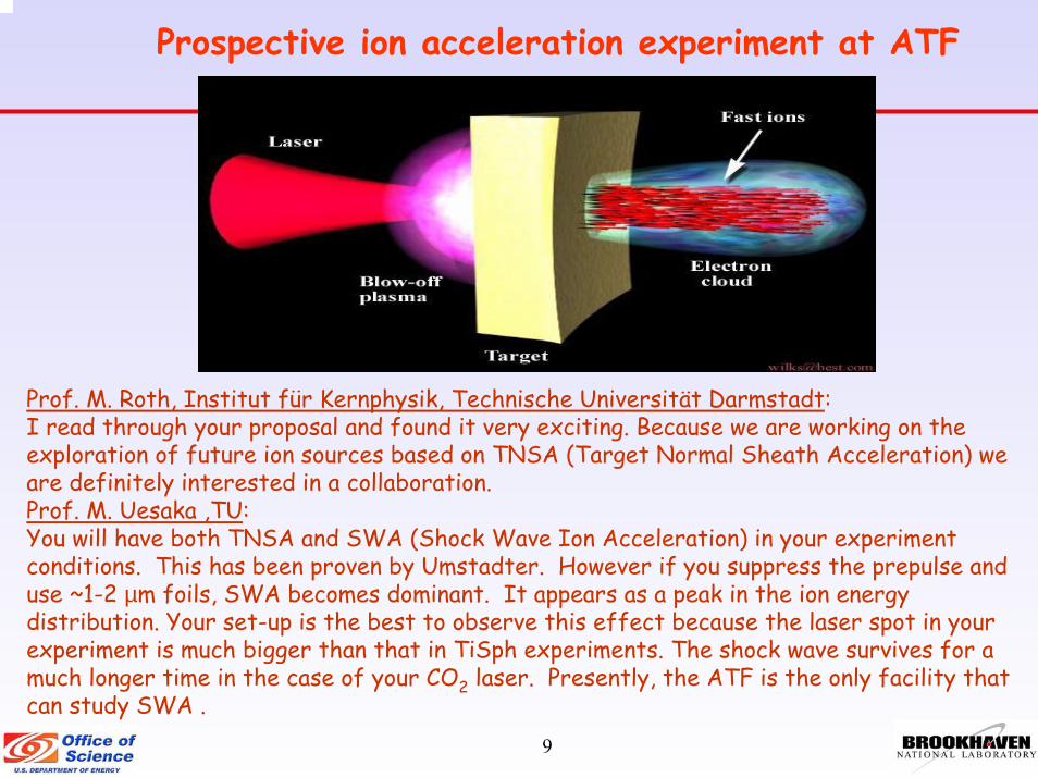
Prospective ion acceleration experiment at ATF
Prof. M. Roth, Institut für Kernphysik, Technische Universität Darmstadt:I read through your proposal and found it very exciting. Because we are working on the exploration of future ion sources based on TNSA (Target Normal Sheath Acceleration) we are definitely interested in a collaboration.Prof. M. Uesaka ,TU:You will have both TNSA and SWA (Shock Wave Ion Acceleration) in your experiment conditions. This has been proven by Umstadter. However if you suppress the prepulse and use ~1-2 µm foils, SWA becomes dominant. It appears as a peak in the ion energy distribution. Your set-up is the best to observe this effect because the laser spot in your experiment is much bigger than that in TiSph experiments. The shock wave survives for a much longer time in the case of your CO2 laser. Presently, the ATF is the only facility that can study SWA .

10
Purpose: A physical study on CO2 laser intensity to achieve the highest Conversion Efficiency from a liquid Xe target.Overview: CO2 and Nd:YAG lasers irradiate a Xe liquid jet target. The CO2 laser is the main beam and the Nd:YAG laser is a pre-pulse. Measurement parameters are; 1) laser power, 2) laser pulse width, 3) delay time between main and pre-pulse laser, 4) EUV power, 5) EUV spatial emission image, 6) ion energy (Faraday cup), 7) spectrum.
0
0.02
0.04
0.06
0.08
0.1
0.12
0.14
0.16
0.18
0 1E+10 2E+10 3E+10 4E+10 5E+10 6E+10 7E+10
C o2 intensity [w/cm 2]
Co2 C.E. [%]
45ns
pre+45ns
15ns
pre+15ns
X 1.5
X 1.3
Xe-Jet : φ280
X 3.4X 2.4
X 2.4
C E increases with increase of intensity
CO2 Laser induced EUV experiments at BNL
EUVA collaborates with Intel in the development of a 100W 17 nm source for EUV lithography using a 30 kW CO2laser. Experiments at the ATF canstudy extreme regimes not accessible at the EUA facility.

11
PASER: Particle Acceleration by Stimulated Emission of Radiation
A 70 MeV electron beam is modulated in a wiggler by a CO2 laser beam.
The bunched beam is injected in a cell containing a CO2 mixture of gases (CO2:N2:He).
Diamond windows will separate the pressure vessel from the high-vacuum beamline.
The experiment passed safety approval and is ready for installation.
FEL
CO2 Laser
Accelerator CO2 Mixture Diagnostics

12
SS
S
SS
S
NN
NN
NN
ELECTRONBEAM
UNDULATORMAGNET ARRAY
LASERBEAM
ψ/2π
-0.4 -0.2 0.0 0.2 0.4
Num
ber o
f Ele
ctro
ns
0
50
100
150
200
250
300
350
400
IFEL experiment evolved into a “Micro-bunch Factory”enabling a new generation of experiments
• STELLA-IFEL (completed)• HGHG (completed)• Resonance PWFA• Optical Stochastic Cooling of beams in RHIC• PASER• Laser pulse-length measurement

13
Observation of Cohesive Acceleration and Focusing of Relativistic Electrons in Overdense Plasma, Phys. Rev. Lett. 91, 014802 (2003)
X E∆∆E60Me V59.4 Me V60.6 Me VX E∆∆E60Me V59.4 Me V60.6 Me VσE 10
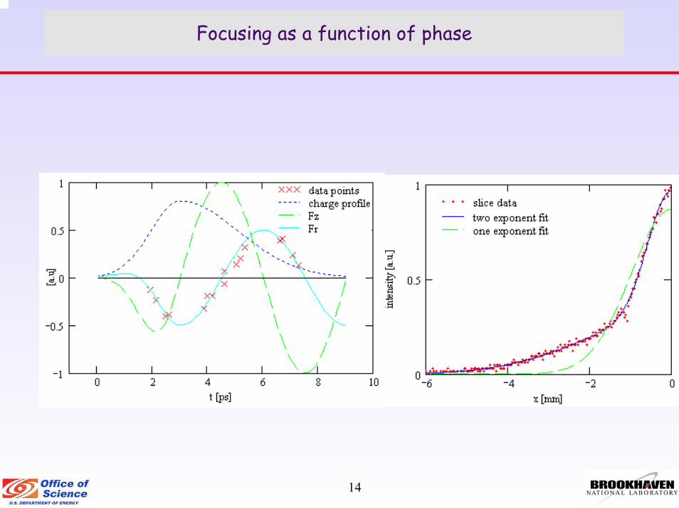
14
Focusing as a function of phase

15
Optical Stochastic Cooling for RHIC
Microwave [λ=50 mm] Optical [λ=10 µm]2d sn eN≈
3i
sl
NN λσ
=Γ
ideald sn N≈
• 16 s cooling time with unlimited laser power.• In practice, cooling time is limited by the laser amplifier.• ~1 hr with 16 W
Nobel prize in 1984e=2.7182…

16
Amplified signal
ωs
ωp
Pump Laser
Nonlinear crystal CdGeAs2
ωi = ωp - ωs;kp = ks + ki
ion beam
d36 = 236 pm/V
λpump = 5.3 µm (Doubled frequency CO2 laser)λsignal = 12 µmPL = 20 MW/cm2 (damage threshold)3 cm length crystal → intensity gain 3x10⁵
ωs
ωp
Broadband CW Parametric Amplifier

17
Experiments
5 active experiments• A SASE-Free Electron Laser Experiment, VISA,
at the ATF Linac, UCLA• Structure-based Laser Driven Acceleration in a
Vacuum, National Tsinghua Univ., BNL • Photocathode R&D, BNL• Electron Beam Pulse Compression Based Physics
at the ATF, UCLA• Study of Compton Scattering of Picosecond
Electron and CO2 Beams [Tokyo Metropolitan U, Waseda U, KEK, Princeton U
Feasibility studies and LDRD• Stony Brook Univ. : X-ray generation from target • Kyushu Univ.: CO2 Laser induced EUV• Univ. of Texas: Application of thin SiC films to
sub-wavelength lithography and compact particle acceleration
• RHIC/BNL: Magnetized beam transport• LDRD: Optical stochastic cooling of Gold ion
beams in RHIC
6 experiments scheduled to start in 2005
• Ultra-fast Detection of Relativistic Charged Particles by Optical Techniques, BNL, Montclair State University, Univ. of Pittsburgh
• Laser Driven Cyclotron Autoresonance Accelerator, Omega-P/Yale
• Particle Acceleration by Stimulated Emission of Radiation (PASER), Technion, Israel.
• Multi-bunch Plasma Wakefield Acceleration, Univ. Southern California
• Laser Wakefield Acceleration Driven by a CO2 Laser, STI Optronics
• Emittance Optimization Using Active Transverse Laser Shaping, Duke Univ.

18
ATF publications
05
1015202530354045
1991
1993
1995
1997
1999
2001
2003
2005
Year
Nu
mb
er
of
pu
blic
atio
ATF Statistics
Run time: ~ 1000 hour/yearGraduated students: 20Current number of experiments: 11Staff members: 11, 1 visitorPhys Rev X: ~ 3/year since 1995
ATF Experiments
0
510
15
1989
1994
1997
1999
2001
2003
2005
Year
Num
ber o
f ex
perim
ents
ATF Graduating Students
0
5
10
15
20
25
1992
1994
1996
1998
2000
2002
2004
Year
Num
ber g
radu
atin
g p
year
and
cum
ulat
ive
Cumulative
Annual

19
What is new at the ATF:
In August 2004, after 15 years as director of the ATF, Ilan Ben-Zvi decided to step down to devote his energy to the electron-cooling project for the Relativistic Heavy Ion Collider at Brookhaven and R&D for the associated energy-recovery linac. He has passed the helm of the ATF to his deputy, Vitaly Yakimenko.The facility performance continues to be enhanced:
A new RF photo injector, a bunch compressor and a control system (Summer 2004). A new record in beam brightness was achieved due to novel cavity tuning.Multiyear CO2 laser upgrade to the Terawatt level (nearly completed; first experiment produced excellent data and confirmed laser performance at ao~0.8).Radiation and laser interlock systems upgrade (this and next years).Photo injector laser upgrade: shorter pulse for CO2 laser, better pulse for RF GUN (next 3-4 years, partially funded by user experiment)Addition of X-bend section after the bunch compressor. (Establishing collaboration with SLAC who will supply cavity and waveguide. Need klystron and modulator [~$1M]. Unique position to investigate high brightness beam in warm X-band structure - ILC nonlinear bunch rotator.)Energy upgrade to ~ 1 GeV and a new experimental hall. (Discussions with users to determine correct energy options. Will be based on the energy recirculator and could give ORION type performance level [~$3M].)
20
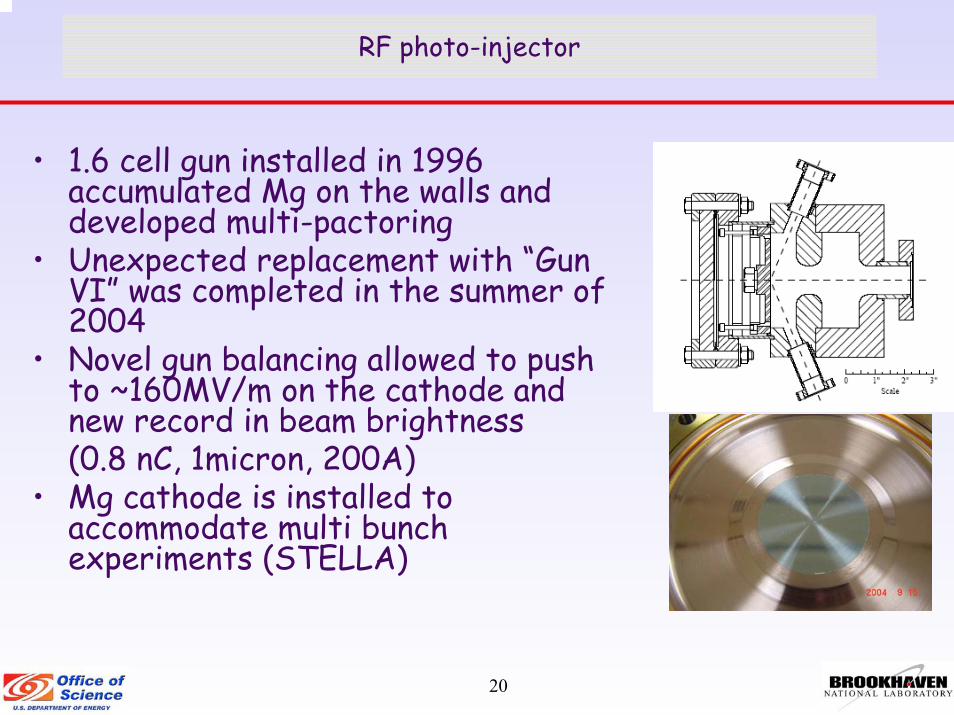
RF photo-injector
• 1.6 cell gun installed in 1996 accumulated Mg on the walls and developed multi-pactoring
• Unexpected replacement with “Gun VI” was completed in the summer of 2004
• Novel gun balancing allowed to push to ~160MV/m on the cathode and new record in beam brightness (0.8 nC, 1micron, 200A)
• Mg cathode is installed to accommodate multi bunch experiments (STELLA)

21
CO2 laser status and prospects
• Until 2004, operated at the 180 ps 50 GW level. • The relatively long pulse duration was due to a narrow bandwidth of a
preamplifier. • A 10-atm preamplifier acquired at the end of 2003 allowed upgrade to 30 ps,
0.5 TW• In 2004, we continued upgrade of the front end picosecond pulse generator
and achieved 10 ps 1 TW regime• Next steps: a new oscillator (installed in March) and a 3-ps upgrade.• Sub picosecond level requires 1 micron laser upgrade

22
Completed upgrade of the ATF CO2 laser to TW peak power
gKe rr g ene ra tor 10 p s

23
Advanced Drive Laser – Approach
The ATF Nd:YAG system has demonstrated excellent performance and is aging well, yet some subsystems are over 20 years old; a replacement is now overdue and we have started development of a purpose-built next-generation drive laser.
Better performance than standard off-the-shelf Ti:Sapphire or other laser systems will be achieved by:Relying exclusively on directly diode-pumped systems instead of more complex, large and failure-prone lasersUtilizing efficient hosts lasing at 1 µm in a mixed gain media configuration to minimize thermal issues and reduce system sizeIntegrating high-level commercial components in-house to minimize development time while maintaining local expertiseContinuing to provide optical synchronization of facility by seeding additional amplifiers for CO2 laser slicing & near-IR TW laser and reducing the CO2 laser pulse duration to 1 picosecond.

24
Advanced Drive Laser – Goals
• 100 µJ UV available on cathode (3x more than now)• Energy jitter 0.2% rms, ~ 1% p-p (5x better than now)• Timing jitter < 200 fs rms (already demonstrated)• Profile uniformity ≤ 5% p-p
(from desired arbitrary profile) (3x better than now) • Pointing jitter ≤ 1% p-p (already demonstrated)• Temporal shaping (expect sub-ps temporal resolution)• Fast turn-on (already under 15 minutes)• High reliability (already provide >1500 hours/year)• Simple operation (~turn-key) (almost there now!)

25
ADL - Development Plan
Year Goals ExpensesATF Users
2005 Verify fiber preamp 1 fiber preamp 1 assembly with 30short pulse diagnostic (FROG 18miscellaneous optics and 15
Prepare oscillator & preamp Postdoc 25 502006 Test fiber preamp 2 multimode fiber 3
pump diodes 25misc optics 10
Assemble & test final Yb:S-FAP amplifier crystal 10seed from preamp chain pump diodes 15
Pockels cells 20misc optics 20Postdoc 30 45
2007 Integration of final gun new beam transport to gun 15temporal shaper 40Miscellaneous optics 20Postdoc 75
298 150
Cost (K$)

26
ADL – Spatial Shaping w/Micromirrors
Shaping of an Optical BeamShaping of an Optical Beam
Inpu
t Sign
al
Inpu
t Sign
al2 nd
order
output
2 ndorder
output
-2nd
order output
-2nd
order output
Mirror tilt axisMirror tilt axis
Intensity Profile
Intensity Profile

27
X-bend installation
Summary of beam parameters with and without x-bend section in the H line.
0.3 – 0.1 %1 – 0.05 %Energy spread (RMS)
0.25 – 2.5 ps0.25 – 2.5 psBeam length (RMS)
100 MeV75 MeVMaximum beam Energy
With X bend S bend only
• Energy chirp compensation in compressed beam
• Increase in beam energy available to experiments
• New capability for measurement and manipulation of longitudinal phase space

28
X-bend installation timeline
• Collaboration with SLAC (summer 2006)• Modulator construction (06/2005 – 06/2006)• Low level RF (3/2006 – 6/2006)• Klystron test 6/2006• Section installation 7/2006
• Additional $100K in capital budget is needed.• This plan relies on receiving x-bend section, waveguide
components and klystron from SLAC
• Plasma Wakefield Acceleration experiments would be the main beneficiary of this upgrade

29
Energy upgrade
• Energy upgrade to 1.5 GeV can be realized by adding recirculation loops
• Benefits are:– Multiple energies would be available– New experimental floor– No interference with existing
operations– Relatively inexpensive…
• Space is available (currently used by RHIC vacuum group)
• User input is being investigated…• Cost of the upgrade is estimated at
$3M

30
ATF Org. chart
DOE BES D. Gibbs, ALD –(Contact)
S. DawsonChair, Physics Department
V. YakimenkoDirector ATF
External program committeeS. Chattopadhyay, Chair
M. WoodleMechanical Engineer
T. CorwinElectrical/Mechanical
Technician
I. PogorelskyLaser Physicist
I. PavlishinSr. Research Associate,
Laser
D. DavisMechanical/Laser
Technician
VacantResearch Associate,
AcceleratorM. Babzien
Laser Engineer
DOE HE,S.Aronson, ALD – (Contact)
DOE NPProposal for 2006
R. MaloneSr. Tech. ArchitectComputer Control
K. BergesenSoftware Designer
A. Karostoshevsky,Mechanical Designer
K. KuscheSafety Engineer,K. Tuohy
Group Secretary
M. MontemegnoElectrical Engineer
DOE FESProposal for 2006

31
ATF HEP Budget Analysis: FY03/07 ($K)
PROJECT FY03 FY04 FY05(cur) FY06(req) FY07(req)• ATF Ops $ 1,680 $ 1,800 $ 1,800 $ 1,910 $ 2,025• ATF Equ $ 200 $ 200 $ 200 $ 130 $ 130• ATF (BES) $ 500 $ 500 $ 500 $ 500 $ 500(??)
Totals: $ 2,380 $ 2,500 $ 2,500 $ 2,540 $ 2,655Needs: 2,884 3,000Missing: 346 345FTE’s(assumed) 7.5 8.3 8.5 9.0 9.0
ATF BR KA 1501020BES BR KC 0204011 n.b. to date there is only a concurrence from BES that FY05/06 funding will be provided. No
FY07 and out year agreement at this time. n.b. Proposals have been submitted to NP and FES for FY06-FY08 for $350k/year each.
ATF continues to be staffed at a minimal level:any reduction in staff would lead to the dramatic reduction of the available run time, currently at
~1000 hours/year, or possible loss of capabilities, e.g. terawatt CO2 laser system.Small increase in staff needed since users are now prohibited from performing certain tasks e.g.
laser operation

32
What “critically low” staffing means:
• Most ATF experiments require simultaneous operation of the accelerator, two lasers and the control system. Minimal staff of 9 FTEs is needed:
– 2 FTEs: Electron beam accelerator, maintenance & operation, group leader, operator trainer. (safety requires turn on and tune-up be performed by a staff operator)
– 1 FTE: Photo injector laser, maintenance & operations (for safety reasons, users are not permitted in the laser room) (only partial substitution for vacation or emergency)
– 1 FTE: Terawatt CO2 laser system, maintenance & operation (users are not permitted in laser rooms or to perform alignment in experimental hall due to safety considerations) (no substitution, additional 1 FTE is needed to support and for “laser only” experiments)
– 1 FTE: Computer control system (no substitution, additional 0.5 FTE needed)– 1 FTE: RF systems maintenance, electrical experiments integration– 0.5 FTE: Experimental safety reviews and vacuum system– 1 FTE: Mechanical maintenance for lasers & accelerator – 1 FTE: Electrical maintenance for lasers & accelerator– 0.5 FTE: Administrative support– ATF subcontracts on a need basis for services in mechanical engineering, radiation and laser
interlocks systems• Reduction in staff would require users to operate some of the critical systems.
Safety, reliability and efficiency of experiments would suffer.– Best scenario: It takes at least 3-6 months to train an accelerator operator. Therefore
reduction of 1 FTE (Linac operator) would eliminate all small scale experiments (~1 month of runtime) and reduce the number of active experiments to ~4. (FACTOR OF 4 REDUCTION)
– DOE safety regulations prohibit the operation of a class IV laser by graduate students (typical ATF user) without continuous supervision
• Replacement of ageing equipment for reliable operation has required capital fund expenditures at the level of 200K in the past years.

33
Summary
• ATF serves as an example of how a user facility is extremely useful to the future of accelerator based R&D in HEP, BES, NP and FES science.
• Many laboratories around the world utilize technologies developed and tested at the ATF (1.6 cell RF gun, Inverse FEL, High Gain Harmonic Generation, …)
• More then 20 students received their PhDs at the ATF over the years (4 more are expected this year).
• The ATF electron beam holds the world record in brightness for the last 9 years.
• Unique terawatt-level CO2 laser system is among the most powerful in the world (when scaled due to a 10.6 µm wavelength) and operates at 0.05 Hz rep. rate
• ATF is looking to obtain funding from NP and FES to support experiments in corresponding areas building on unique equipment and expertise at ATF.
• 2006 and 2007 budget plans lack sufficient capital funding to cover necessary upgrades (operations will suffer).
• ATF has insufficient staff for efficient utilization of it’s unique capabilities. Many staff positions have no substitutes (conferences, vacations, … lead to downtime).

34
ATF user meeting
You are all invited to the ATF User Meeting to learn in depth about :
• Facility capabilities and upgrades• Exciting results from completed experiments• Fresh ideas for new experimental proposals
We plan to have next meeting in the Fall of 2005, (last one was held in January of 2004).
New APAC Chair is S. Chattopadhyay, JLAB. He will replace C. Joshi, UCLA.