Embed Size (px)
Citation preview

12/21/2005 1
Accelerator Technology and High Gradient Collaboration
Sami TantawiSLAC

12/21/2005 2
Outline• The US High Gradient Collaboration for Multi TeV
Linear Collider
– Introduction: motivation, governance structure, members, scope, and methodology.
– Technology developments for high gradient studies• High Power RF devices and related technologies
– RF components– RF sources at high frequencies (22.8-30GHz)– Active Pulse compression at high frequencies
• Accelerator structure developments and related art– Some lessons learned from the NLC/JLC program– Waveguide experiments for material and geometrical studies– Single Cell Accelerator structure studies– Novel Accelerator structures

12/21/2005 3
Outline Continued• Advanced Concepts for the ILC
– Positron Capture Section– Modulators– RF distribution system– RF sources – Fundamental mode Couplers
• Technology Research– Advanced Electronics – RF undulators– Solid state RF sources– Applications of RF ideas to optical acceleration

12/21/2005 4
US Collaboration on High Gradient Researchfor a Multi-TeV Linear Collider
Motivation• The ILC will reach ½ to 1 TeV cm energy.• Advanced Accelerator research looking far beyond this,
exploring laser and plasma acceleration• Multi-TeV energy maybe to be reachable with extension of
normal conducting high gradient technology.• The CLIC Two-Beam approach offers a power source which is
not so frequency specific—from 11-30 GHz at least.• After extensive development, NLC achieved reliable 65 MV/m
for collider-ready structures (achieved much higher gradients in selected tests!).
• Multi-TeV colliders need higher gradient—CERN specifications have been 150 MV/m loaded.
• This collaboration should aspire to build the bridge to span this gap.

12/21/2005 5
• Current Members:– Laboratories:
• Argonne National Laboratory • Lawrence Berkeley National Laboratory • Naval Research Laboratory• Stanford Linear Accelerator Center (also the host of the collaboration)
– Universities :• University of Maryland• Massachusetts Institute of Technology
– Business Associates• Omega-P, Inc.• Calabazas Creek Research, Inc.• Haimson Research Corporation• Tech-X Corporation• Communications and Power Industries
– Foreign Colleagues• CERN• KEK
US Collaboration on High Gradient Researchfor a Multi-TeV Linear Collider

12/21/2005 6
• Governance Structure – Spokesman
• Selected to lead this effort by the directors of SLAC and Fermilab at the request of the DOE, Prof. Ronald Ruth of SLAC
– Advisory Council• Prof. Sami Tantawi of SLAC (11.4 GHz research/overall
technical coordination); • Dr. Richard Temkin of MIT (high frequency research and RF
source development); • Dr. Gregory Nusinovich of UMD (theory and code development) • Dr. Wei Gai of ANL (other experimental programs).
– Scientific Secretary• Dr. Christopher Nantista of SLAC has been selected to be the
current collaboration Scientific Secretary.
US Collaboration on High Gradient Researchfor a Multi-TeV Linear Collider

12/21/2005 7
US Collaboration on High Gradient Researchfor a Multi-TeV Linear Collider
Scope• This collaboration should not be viewed as an umbrella for
general research into RF accelerator technology or other advanced accelerator techniques. – For example, the general development of RF sources, modulators,
and RF components is not included in this effort.• Specific technology may be included, provided that it is
required for achieving the goals expressed in the introduction.
• As our research proceeds, the collaboration may enhance or limit the scope of our work plan to include additional techniques or technologies which address the primary goal of the achievement of high acceleration gradient.

12/21/2005 8
US Collaboration on High Gradient Researchfor a Multi-TeV Linear Collider
Methodology
• We have to address fundamentals early.• This research and development effort will aim to establish a better
understanding of the frequency scaling of the limiting gradient, as well as its dependence on material, surface preparation, structure design, pulsed heating, etc.
• It will include studying the rf breakdown phenomenon itself, theoretically and experimentally.
• It will explore the high gradient barriers due to choices made in linear collider programs to date.
• The experimental side of this effort will entail the upgrade of test facilities and the development of new high-power rf sources specifically designed for high gradient testing.
• The final goal is to produce and successfully test at very high gradient an accelerator structure suitable for use in a multi-TeV two-beam linear collider.

12/21/2005 9
Technology developments for High gradient studies
High gradient studies require:• High Power RF devices and related
technologies• Accelerator structure developments and
related arts
We will present a brief review of the state of the art in these topics then move to the planned work

12/21/2005 10
High Power RF-technologyAt SLAC we have a strong program in the developments of
high-power RF components:– Multi-moded RF Compnents:
These types of multi-moded components enabled us to build state of the art pulse compression and RF distribution systems.
Sled Head Simulations

12/21/2005 11
Ultra-High Power MultimodedPulse Compression Systems
Dualmode Resonant Delay lines ~30m
RF Input to the 4 50 MW klystronsSingle mode waveguide input to
the pulse compression system; 100 MW/Line for 1.6 µs
Dual mode waveguide carrying 200 MW
Compressed output > 600 MW 400 ns.
Output Load Tree
NLC experimental rfpulse compression
system

12/21/2005 12
High Power RF-technology
0
1 0 0
2 0 0
3 0 0
4 0 0
5 0 0
6 0 0
0 0 . 5 1 1 . 5 2
I n p u tO u t p u t
Pow
er (M
W)
T i m e (µ s )S a m i T a n t a w i ( 1 / 2 7 / 2 0 0 4 )
Output of the Experimental NLC Pulse Compression System

12/21/2005 13
Summary of SLAC X-band RF Facilities
• NLCTA (3 RF stations, one Injector, one Radiation shielding)– Two 240ns pulse compressor, 300 MW peak, powered by two X-band 50 MW klystrons – One 400 ns pulse compressor, 500 MW peak, powered by 4 X-band 50 MW klystrons
(being reduced in size to 300 MW peak, powered by two 50 MW klystrons)– 65 MeV injector with a 1 nC charge/bunch– Shielding enclosure suitable for up to 1 GeV
• Klystron Test Lab (3 RF stations, 3 modulators, 2 shielding enclosures)F Stations– Stations 6 and 8, two 50 MW klystrons that can be combined and 150 ns pulse
compressor that can produce up to 480 MW. – Station 4, 50 MW klystron, – Station 1, 50 MW klystronModulators– Station 2, ~500 kV, ~200 A modulator– Station 13, ~500 kV, ~200 A modulator– Station 3, 500 kV, ~xxx A modulatorRadiation Shielding– A shielding enclosure suitable for up to 100 MeV (ASTA Bunker)– A shielding enclosure suitable for up to 5 MeV

12/21/2005 14
High Power RF-technologyPlanned developments for RF systems and components
– New control components to enhance the RF test stations• Phase shifters• Controlled iris• Windows • RF gate valves
High Power over-moded phase shifter, used to divert the power from one experimental output to another
Over-moded TE01 Tee, a variable iris to be used with pulse compression system to change the compression ratio and the pulse width

12/21/2005 15
High Power RF-Technology22.8-30 GHz RF Sources and related technologies
– Several RF sources have been proposed at these high frequencies,including, gyrotrons, gyroklysrons, sheet-beam klystrons, magnicons, Harmonic Converters, etc.
– The Gyrotron is our best bet for a workhorse device in a shortperiod of time.
• If we buy this device only CPI can do it and they will probably team with MIT and Maryland for theoretical support.
• If we make it we will use the same people with the addition to SLAC’sexperience to make electron guns. In this case we will have all the world experts working on this at the same time. It will also force us to talk to each other and collaborate.
• No matter what, this is a research device and the risk is high.• All the first and second generation experts, within the US, on Gyro
devices are in this collaboration
– We have been successful in getting the rest of the collaboration to follow our lead on this matter!

12/21/2005 16
High Power RF-technology22.8-30 GHz RF Sources and related technologies
– Using an oscillator source requires an active pulse compression system.
– CERN also needs an active pulse compression system because of the difficulty of fast switching of the driving beam phase.
– Collaboratively we will develop this system based on our old ideas of optically controlled RF pulse compression system.
Output
Flower Petal ModeConverter
InputLaser Light (Green @ 532 nm)
Nd:Yag Laser
CirculatorActive Iris
A 68 nS Delay Line.Silicon Wafer
Mode Transducer
TE01 Choke
Sapphire Window
0
8000
1.6 10 4
2.4 10 4
3.2 10 4
4 10 4
500 1000 1500 2000 2500
InputOutput
Pow
er(W
atts
)
Time(nS)
Cr=32, Gain=11

12/21/2005 17
Technology developments for High gradient studies
High gradient studies requires:• High Power RF devices and related
technologies• Accelerator structure developments and
related arts
We will present a brief review of the state of the art in these topics then move to the planned work

12/21/2005 18
High Gradient Performance of Five Structures after ~ 500 hr of Operation and of 8 Structures (Averaged, 4 in Common) after > 1500 hr of Operation
Unloaded Gradient (MV/m)
Brea
kdow
n R
ate
at 6
0 H
z (#
/hr)
Design Rate Limit(~100% Availability)
Rate Limit for 99% Availability
FXB6
FXB7 FXC3
4R17-2
4S17-1Eight Structure Average
Performance of the NLC/JLC Structures

12/21/2005 19
Accelerator structure developments and related arts
• Developments that have led to high gradient accelerator structures are:– Geometrical manipulation of the gradient
along the accelerator structure– Novel fundamental mode couplers
• To a much lesser degree, processing and manufacturing techniques.

12/21/2005 20
Structure Design Optimization for Efficiency and High Gradient Performance
RF Structures Group
Comparison of maximum iris surface field for different structure designs at an unloaded gradient of 65 MV/m. The red curve is for H60VG3N (a/λ=0.18), which has rounded shaped irises – the others have elliptical shaped irises, which lowers the peak field. This structure also has a reduced field in the first several cells. The green curve is for H60VG3S18 (a/λ=0.18), which shows the effect of the elliptical shaped irises. The light blue curve is for H60VG3S17
Accelerator structure developments and related arts

12/21/2005 21
T53V
G3M
C S
truct
ure
Gra
dien
t (M
V/m
)
Time with RF On (hr)
Processing History of Structure (T53VG3MC) with Upstream Mode Launcher Coupler and Downstream Fat-Lip Coupler
1Trip / 25 Hours
400 ns Pulse Width
1 Trip / 25 Hours
NLC/JLC Trip Requirement:< 1 per 10 Hours at 65 MV/m
The rate is 1 trip / 24 hours at 90 MV/m

12/21/2005 22
Accelerator structure developments and related arts
• Basic Physics experimental studies– We have two vehicles for these studies
• Waveguides • Single cell accelerator structures• Unlike full scale accelerator structures, these are amenable to
simulations• Pulsed heating experiments for different materials using
“mushroom” cavity– The experiments are guided by theoretical models
• One model reproduce experimental observations: – Power x (Pulse width)1/2 is constant for a given breakdown rate– material data to date
• It predicts that beryllium and chromium are better materials

12/21/2005 23
Accelerator structure developments and related arts
Waveguide studies Two waveguides with identical electric fields for a given power distributed over the same area, and completely different magnetic field distribution
Magnetic Field distribution
Waveguide High Gradient Study: Maximum breakdown electric fields for different Materials
Planned waveguide tests:Molybdenum waveguideStainless steel high magnetic field waveguideChromium waveguide

12/21/2005 24
Reusable TM01 Mode launchers reduce experimental costs
Single Cell TW structure
Accelerator structure developments and related artsSingle Cell Accelerator Structure
Goals• Study of RF breakdown in practical
accelerating structures, dependence on circuit parameters, materials, cell shapes and surface processing techniques in a structure which is amenable to simulations

12/21/2005 25
Accelerator structure developments and related artsPulsed heating/superconducting material testing
TE01
At high frequencies pulsed heating becomes the limiting factor for high gradient operations of copper structures. Can be helped by using different materials, e.g. copper-zirconium.
•Easy setup for testing materials with a demountable sample holder.
•The setup depends on our state-of-the-art mode converters and cavity designs.
•We will use this set-up to test superconducting materials, and materials for pulsed heating.
•Samples are supplied from CERN, LANL, JLAB, SNS and the list is growing.
•We are yet to conduct our first high power experiments.

12/21/2005 26
Accelerator structure developments and related arts
SLAC’s future program on high gradient research• Novel Accelerator Structures.
– Distributed coupling accelerator structure ( to leverage what we learned about geometrical effects)
– Dielectric Accelerator structures at high frequency (we may be able to do experiments at 90 GHz if the CCR Inc 10 MW gyroklystron test is successful)
– Heavily damped structures are being studied at CERN, MIT and University of Colorado.

12/21/2005 27
Advanced Concepts for ILC

12/21/2005 28
Advanced Concepts for the ILC• Projects funded by the GDE
– Positron capture source– Modulators
• At the moment some of the following projects are just paper designs and theoretical developments.
• Some of the concepts might get funded through other channels (SBIR/STTR, collaboration with other institutes such as KEK, etc., or hopefully by the GDE if the concept is mature enough)
– Fundamental mode couplers– RF distribution systems– RF sources– RF undulators for polarized positron production – Fast Kickers for the damping ring– Active switches for charging and discharging
superconducting cavities

29
Schematic Layout of the ILC Positron Source
S.C. Coil
Bucking Coil
Solenoid
Bunch Compressor I
Target
e-, γ Stopper
S.C. Linac
250 MeV125 MeV
CaptureSection
Two 2.15 mTW Sections(In RF Series)
N x 4.3mTW Sections
Triplet

12/21/2005 30
5-Cell Test SW Structure for Positron Capture Section
TH2095A or TH2104U klystron 5 MW peak power, 1 ms, 5 Hz.
3.8 MWPower needed at 15 MV/m
2.0 / 0.69∆T (Average/Transient) oC
6.8 kW/cell
3.6 kW/cell
34.3 MΩ/m
29700
18 mm
60 mm
5
Disk thickness
Particle Pd
RF Pd at 15 MV/m
Shunt impedance r
Q
Aperture 2a
Cell Number

12/21/2005 31
1. We have a baseline design. 2. More detailed studies and optimization are
underway.3. SW test structure
• Mechanical design is nearly finished.• 5-call structure is being fabricated at SLAC shop.
4. L-Band window• Electrical design is nearly finished.• 10 pieces of AL-995 ceramic are being ordered from WESGO.• Mechanical design and fabrication will be started soon.
Progress Summary for Positron Capture Source

12/21/2005 32
The NLC Marx Modulator Concept – circa 2003
• Existing modulator designs could not meet the tight NLC requirements for efficiency, reliability and mean repair time – studied alternative approaches
• Marx topology provided a simple cell architecture, eliminated power magnetics• The ‘step-and-repeat’ nature of the Marx allowed cheaper mass production,
increased reliability, simplified maintenance• Emerging IGBT technologies, telecom chipsets allowed a practical approach for
realizing the Marx modulator concept

12/21/2005 33
The Marx Concept for ILC – circa 2005
• The International Linear Collider requires a pulse length 1000 times longer than NLC.
• Each ILC pulse will deliver 23 kilojoules – roughly the energy of a 20mm cannon shell.
• The new ILC Marx design uses IGBT switches and control system developed for the old NLC prototype design; adds larger capacitors and stepped-delay regulation system.
• Total projected cost savings over existing large, oil-filled, transformer-driven modulators is approximately US$250 million, including the installed cable plant.

12/21/2005 34
Advanced Concepts for ILC• Novel Fundamental mode coupler
WR650
Using TE01 Mode launcher for a dielectric loaded waveguide can make an exceptional fundamental mode coupler. No electric field lines normal to any surface, hence the hope for amultipactor-free structure

12/21/2005 35
Advanced Concepts for ILCNovel Fundamental mode coupler• To test these ideas KEK volunteered the ceramics• We applied for STTR/SBIR fund to build the device• The concept could also lead to novel circulators and switches
Further, a physical gap as large as 1 cm without any loss of RF power would help the design of the cryomodule

12/21/2005 36
Advanced Concepts for ILCRF distribution system • We made the only mathematical model for this system. • These ideas are being tested at KEK
If one couples 8 or more accelerator structures, ideally, one would eliminate circulators. At a minimum their number could be reduced by a factor of 8.
0 2 4 6 8 10Delta Separation cm
25
20
15
10
5
0
noitc elfeRo t
ehtecr uos
Bd

12/21/2005 37
Advanced Concepts for ILCRF Source Options• There is sweet spot when coupling 8 accelerator
structures, optimizing the RF system as whole; this needs a 2MW RF source.
• One can go to the extreme of one RF source per coupler, thus eliminating the distribution system, while keeping circulators. Solid state RF sources and magnetrons are good candidates, substantial improvements in the cost of the modulators are also possible.
• Inexpensive replacement of the klystrons with a sheet beam klystron

D. Sprehn12/07/05
ILC Sheet Beam Klystron (ILC SBK)
ILC SBK is designed as plug-compatible with existing 10MW MBK’s
• 110kV, 130A 1.3GHz
• Cathode currents for long life– < 2 A/cm2 average
• Same rf performance as MBK’s
• Uses permanent magnets instead of solenoid
• Identical window technology

D. Sprehn12/07/05
ILC Sheet Beam Klystron (ILC SBK)
Advantages of SBK compared to MBK technologies favor further investigations
Cheapest alternative known – single beam instead of multiple beams– One cathode, one set of cavities, one drift tube, one collector and simple output
coupling– Fewer parts means less procurement costs, less machining, less inspection,
fewer assembly hours, less weight, fewer brazes and higher assembly yield– No solenoid power required, SBK uses PCM permanent magnet focusing
Potentially a more stable and robust design– Only one beam-formation through rf interaction circuit to design and maintain– No (N-n)/N degradation near end-of-life (N=number of beams in MBK)– Less chance of mechanical failure (fewer parts, fewer brazes, no solenoid)

12/21/2005 40
Technology Research

12/21/2005 41
Advanced Electronics• Development of
reconfigurable high-speed signal processing systems for accelerators
• Development of wideband electronic and optoeletronictechnology for ultrafastapplications

12/21/2005 42
Applications of Instability Control to Light sources
This technology have been applied to 3 different light sources
Feed back at the ALS narrows the line width and doubles the intensity

12/21/2005 43
Application to PEP-II: Low group delay woofer
• Decoupled low-mode and HOM channels allow independent optimization of loop gains and dynamic ranges
• Permitted increased PEP-II currents (1380 -> 1800 mA)

12/21/2005 44
RF Undulators• The idea of using high-power microwaves in a waveguide as
an undulator is old.• Our recent advances in high-power rf pulse compression
systems and rf sources at x-band make this type of undulator practical and a competitor to static magnetic undulators for SASE FEL
• This type of undulator is also an attractive alternative for polarized gamma production to generate polarized positrons for the ILC
• This type of rf undulator has several attractive properties that makes it a very attractive alternative to magnetic undulators:– An rf undulator can be useful when a short electron oscillation
period and a large aperture for the propagation of the beam are needed.
– The polarization of the rf, and hence the polarization of light, can be controlled at will using the rf source.
– The system can also offer economical advantages over static undulators.

12/21/2005 45
RF Undulators• Jointly with a UCLA group (C. Pellegrini and J. Rosenzweig
et. al.) we plan to study this type of undulator. We also proposed to do an experiment at the NLCTA enclosure using the existing infrastructure for e-beam and rf sources. In this experiment we will consider putting the undulator waveguide inside a resonant rf ring to enhance and smooth the rf field. The rf pulse would thus be compressed in two stages, first through a SLED–II system and then through the resonant ring.
• Because the idea will also have a strong impact on FEL based light sources we would need to seek BES support for the M&S and engineering support of these experiments. This could become a test case for engaging BES in supporting accelerator based research in our programs

12/21/2005 46
Power from the dual Moded SLED-II pulse compressor (500 MW)
Open Elliptical Waveguide undulator
Low Loss Overmoded waveguide
Mode Launcher
Because of the integration of RF pulses in a resonant ring the rfpulse in the undulator can be smoothed. Further, the ring can have a multiplication factor of more than 10, resulting in 5 GW of RFpower through the undulator waveguide.
- 1 - 0.5 0 0.5 1
- 0.6- 0.4- 0.2
00.20.40.6
Ratio between peak surface field/Field at the center is 1/5
12/21/2005 47
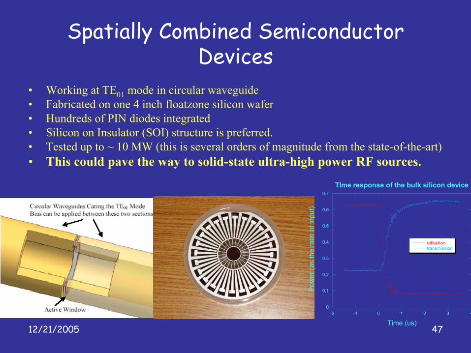
Spatially Combined Semiconductor Devices
• Working at TE01 mode in circular waveguide• Fabricated on one 4 inch floatzone silicon wafer• Hundreds of PIN diodes integrated• Silicon on Insulator (SOI) structure is preferred.• Tested up to ~ 10 MW (this is several orders of magnitude from the state-of-the-art)• This could pave the way to solid-state ultra-high power RF sources.
0
0.1
0.2
0.3
0.4
0.5
0.6
0.7
-2 -1 0 1 2 3 4
TIme response of the bulk silicon device
reflectiontransmission
Pow
er (a
s th
e ra
tio o
f inp
ut)
Time (us)

12/21/2005 48
Optical all-dielectric planar accelerator structure
•Accelerating mode guided by the Bragg waveguide•Grating coupler couples laser light from the side and converts it to accelerating mode•Waveguide and coupler can be fabricated with micro-processing technology
•Low intrinsic loss at near infrared ~ 0.2dB/km•High damage threshold supports accelerating gradient ~ 1GV/m•High power laser source available
Optical Dielectric Accelerator

12/21/2005 49
Final Comments• Most of the technology development
efforts mentioned in this talk are bottoms–up developments, and driven by program needs
• BES facilities build on this fundamental technology development for their operating facilities