Embed Size (px)
Citation preview
32
test loop has 7. 7 km (4 .8 miles) of track and consists of 22 test sections. The purpose of the facility is to subject various track components and types of construction to accelerated testing. The track components and types to be tested cover a wide range of variables; these include rail metallurgy, steel, reconstituted, laminated, concrete, and wooden ties, ballast, rubber pads, tie plates, and many others.
In accelerated tests, appropriate instrumentation should be provided to measure the track response. This instrumentation can be similar to that used in ordinary field tests.
The information generated from verification studies, whether conducted in the laboratory, in the field, or in an accelerated service loop, is useful only to the extent that the test corresponds to actual conditions. Therefore, verification studies should be designed and conducted carefully and, of more importance, the data must be interpreted properly.
CONCLUDING REMARKS
A systematic procedure for the analysis of a track structure is described. The procedure uses methods of analysis that are well developed in the structural engineering field. Methods for verifying the analysis by means of laboratory, field, and accelerated tests are presented.
The present standards of track have been evolved from previous practices through a process involving trial, judgment, and experience. This practice has not yet provided a track structure that fulfills its intended purpose. Therefore, railroad track should be developed in a manner similar to that followed in the development of other engineering structures. Analysis and experimentation can contribute significantly to the orderly development and upgrading of our railroad system.
REFERENCES
1. A, N. Hanna. Railway Track Research: Theoretical and Experimental. Portland Cement Associa!;ion, Research and Development Bull. RD030.01R, 1975.
2. H, Zimmermann. The Calculation of Railroad Permanent Way. W. Ernst and Sohn Verlag, Berlin, 3rd Ed., 1941.
3. "Fifth Prngr<>l'll'l 'R<>pnrt. A~rli'-ARli'A ~P"";.,1 ('nm-
mittee on Stresses in Railroad Track, AREA, Bull., Vol. 31, 1929.
4. H. Luber. Analysis of Elastic-Supported Railway Tracks Under Vertical Loads. Institute for Railway and Highway Construction, Technical Univ. of Munich, Bull. 1, 1962.
5. J. Eisenmann. Theoretical Views on the Stresses in the Rail Head Near the Point of Load Application. Eisenbahn-Technische Rundschau, Vol. 14, No. 12, Dec. 1965, pp. 25-34.
6. A. N. Hanna. Solution of the Stresses in the Rail Due to Lateral Forces. Strasse-BrUcke-Tunnel, Vol. 22, No. 3, March 1970, pp. 70-73.
7. H. Hertz. On the Contact of Solid Elastic Bodies. Joul'nal fiir die Reine und Angewandte Mathematik, 92, 1882, pp. 156-171.
8. A. N. Hanna. Theoretical and Experimental Examination of the Stresses in the Interior of the Rail Head. Institute for Railway and Highway Construction, Technical Univ. of Munich, Bull. 10, 1967.
9. J. Heymann. Semi-Infinite Space Under Uniform Loading with an Elliptical Boundary. Zeitschrift ftir Angewandte Mechanik, Vol. 42, No. 12, Feb. 1963, pp. 568-572.
10. G. C. Martin and w. W. Hay. The Influence of Wheel-Rail Contact Forces on the Formation of Rail Shells. Paper presented at the Winter Annual Meeting, New York, ASME, Nov. 26-30, Paper 72 -WA/ RT-8, 1972.
11. A. N. Hanna. A Contribution to the Clarification of Rail Shelling. Strasse-BrUke-Tunnel, Vol. 24, No. 1, 1972, pp. 8-13.
12. Y. Yasojima and K. Machi!. Residual Stresses in Rails. Bulletin of Permanent Way Society of Japan, Vol. 13, No. 9, 1965.
13. D. M. Burmister. The Theory of Stresses and Displacements in Layer Systems and Applications to Design of Airport Runways. Proc., HRB, Vol. 3, 1943, pp. 126-148.
14. S. Timoshenko and B. F. Langer. Stresses in Railroad Track. Applied Mechanics, Trans., ASME, Vol. 54, No. 23, 1932, pp. 277-293.
15. Stresses in the Rails, the Ballast, and the Formation Resulting From Traffic Loads. Office for Research and Experiments of the International Union of Railways, Utrecht, Netherlands, Question D-71, Rept. 1, April 1965.
16. Concrete Ties (and Fastenings). AREA, Bull. 655, Vol. 77, Nov. -Dec. 1975, pp. 193-236.
Track Structure at Facility for Accelerated Service Testing Ernest Nussbaum, Metrek Division, Mitre Corporation, McLean,
Virginia
An overview of the track structure at the Federal Railroad Administration Facility for Accelerated Service Testing is presented in this paper. The facility consists of a 7.7-km (4.8-mile) loop of relatively conventional railroad track at the U.S. Department of Transportation's Transportation Test Center near Pueblo, Colorado. In September 1976, a loaded freight train began traveling t he loop 16 h/d and was scheduled to continue do·
ing so for 1 year, subjecting the track to as much loading as is hauled over an average freight line in 10 years. Many types, makes, sizes, and arrangements of track components (rails, ties, fasteners, and ballast) are used in the 22 track sections of the loop. The rail elements being tested include five types of rails with varying metallurgy or heat treatment, various frogs and guardrails, jointed and continuously welded rail, insulated
and glued joints, and four turnouts. Steel, prestressed concrete, reconstituted, and laminated ties were installed, in addition to several kinds of wooden ties. Differing arrangements of cut, elastic, screw, and lock spikes are used, as are various special rail fasteners and tie plates. Grcanite, limestone, traprock, and slag ballasts of varying depths and shoulder widths are included. The accelerated service test will provide information on the durability and maintenance requirements of these components. An extensive system of observations and measurements has been scheduled to ensure safety and collect data for immediate and long-range analysis. The results should provide the industry with new tools and knowl· edge to improve railroad safety, reliability, and operating economy.
Figure 1. Transportation J I test center (only main ,-------·---------tracks are shown). ! i
I ~ . . I
L ___ l 0 1 L......L....J •
km I 0 1 L..-J........J
mi
Figure 2. Typical track cross section.
i .
33
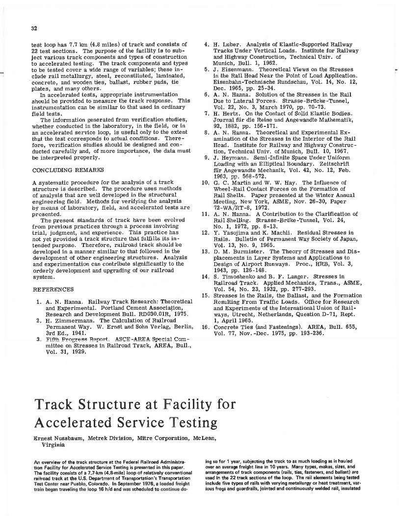
The Transportation Test Center (TTC) occupies an 8.9 by 14.5-km (5.5 by 9-mile) tract of land northeast of Pueblo, Colorado, on the high plateau immediately east of the Rocky Mountains. The Facility for Accelerated Service Testing (FAST) is but the latest addition to a considerable number of research activities there. In terms of length of track, FAST is small among the array of tracks, but in hours of train operation and number of support personnel, it represents one of the largest activities. The layout of TTC is shown in Figure 1.
BACKGROUND AND PURPOSE OF FAST
A railroad track is in some ways a more complicated structure than is a highway and is subject to much higher loads. Freight cars with gross masses of 127 000 kg (140 tons) are common, so that each of the four axle loads is 311 kN (35 tonf)-more than three times the truck axle loads allowed in many states. The initial cost of a track structure is correspondingly high, and much maintenance is required to keep it within required standards of alignment and gauge and to replace the rails and ties that wear out. Track structure has evolved over almost 2 centuries to such arrangements of subgrade, ballast, ties, and rails as are shown in Figure 2.
Although railroads and other agencies have conducted many tests and evaluations of track components, there was felt a need to conduct a comparative test program under controlled conditions. In FAST, these exist to the extent of uniform weather, subgrade, loading, and maintenance.
The purpose of FAST is to compare various types and arrangements of track components under accelerated loading and thus to discover what combinations can yield near-term improvements in railroad safety, reliability, and economy. At the same time, certain aspects of the rolling stock are also being evaluated, e.g., wheel wear. Many of the track components have been used for many years; some have been used more in other countries than in the United States; a very few have been used little or not at all in this country.
PAD
CONCRETE TIE
SUBBALLAST
I
SUBGRADE/
34
Figure 3. Location of track sections. O 0.5
mile 0.5 3°CURVE
MAXIMUM GRADE= 2.0%
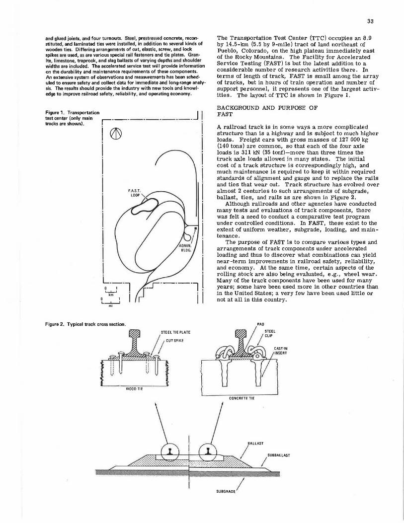
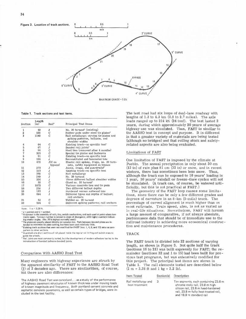
Table 1. Track sections and test items.
Section Length (ml Rall' Principal Test Items
1 52 J No. 20 turnout' (existing) 2 100 C Rubber pads under steel tie plates' 3 1140 C Rail metallurgy; varying tie plates and
spiking patterns, ballasts, and shoulder widths
4 64 C Existing track-no specific test' 5 67 J Bonded rail Joints' 6 91 C Steel ties (removed after 4 months) 7 305 C Special tie plates and fasteners 8 91 C Existing track-no specific test 9 191 J Reconstituted and laminated ties
10 472 J(C on Elastic rail spikes, frogs, no . 20 turn-bypass) outs, safety equipment on bypass
11 273 J Joints, frogs; and guardrails' 12 103 J Existing track-no specific test 13 380 C Rail metallurgy 14 249 J No. 20 turnout 15 396 J Three different ballast shoulder widths 16 52 C Glued no. 20 turnout' 17 1872 C Various concrete ties and tie pads 18 250 J Two different ballast depths 19 183 J Hardwood versus softwood ties 20 694 J Different types and depths of ballast;
rail anchors 21 52 C Welded no. 20 turnout 22 594 C Different spiking patterns; rail anchors
Note: 1 m = 3.28 ft.
.. J • 101ntDd and c; • woldad. b A tumcu1 Is lhe .assamblv of ralls, 1lci, $W'hc;tl medum1t.mf, P(ld tuch u~ed al pofnt where 1wo
track~ meoL Tornou, numb11r ir to.hued to an9lt of dlveroance. with higher numbt!n indlcat· Ing smoilor o~gloo. (No. 20 i, higheu normolly used.)
c T1n platoi are usuallv pl,1~ di reedy on wooden tics. Pi:!ds between 1ies nfld plotei are In~ tended to minlmi>o tic pinto outtlng, but hll~o ix...,, u...:J roJotl,olv llulo.
d ExiJtrng trnc:k ,or:1lor'II thH were not modified for F-AST (nos. I i "1, 8, .and 12) ~No asoom• parison to other sections.
e Guardrails are short sections of rail placed inside the regular rail in frog and switch areas to guide the wheels.
t Rail joints are most commonly bolted, but the development of modern adhesives has led to the introduction of bonded (adhesive-bonded) joints.
Comparison With AASHO Road Test
Many engineers with highway experience are struck by the apparent similarity of FAST to the AASHO Road Test (1) of 2 decades ago. There are similarities of course, but there are also differences:
The AASHO Road Test was conceived . . . as a study of the performance of highway pavement structures of known thickness under moving loads of known magnitude and frequency. Both portland cement concrete and asphaltic concrete pavements, as well as certain types of bridges, were in· eluded in the test facility.
The test road had six loops of dual-lane roadway with lengths of 1.3 to 4.3 km (0.8 to 2.7 miles), The axle loads ranged up to 214 kN (24 tonf). The test lasted 2 yea1·s, during which approximately 20 years of average highway use was simulated. Thus, FAST is similar to the AASHO test in concept and purpose. It is different in that a greater variety of mate1·ials are being tested (although no bridges) and that L'Olling stock and safetyrelated aspects are also being evaluated.
Limitations of FAST
One limitation of FAST is imposed by the climate at Pueblo. The annual precipitation is only about 30 cm (12 in) of rain plus 81 cm (32 in) or snow, and in recent winters, the1·e has sometimes been less s 11ow. T hus although the track can be exposed to 10 years' loading in 1 year, 10 years ' ralnfall or freeze-thaw cycles will Dot be simulated. (A t1·ack can, of course, be watered artificially, but this is not practical at FAST.)
The geometry of the FAST loop causes some limitations, since there can be only a few different grades and degrees of curvature in an 8-km (5-mile) track. The percentage of curved alignment is much higher than on most railroads. Train speed, also, is not as varied as ii, i'eal-liie situaLium;. Nevertheless, FAST will furnish a large amount of comparative, if not always absolute, per.formance data that should be of immediate use to the railroad industry in achieving more economical construction and maintenance procedures.
TRACK
The FAST h·ack is divided into 22 sections of varying length, as s hown In Figure 3. Not quite half the tl'ack (sections 16 to 21) was built expressly for FAST; the remainder (sections 22 and 1 to 15) had been built for p1·evious test programs, but was extensively modified for this project. The principal test items are shown in Table 1. The rail elements tested are described below (1 m = 3.28 ft and 1 kg = 2.2 lb).
Jte111 Tested Section (s) Description
Rail metallurgy and 3 Ten segments, each containing 23.8 m chrome moly rail, 23.8 m highsilicon rail, 23.8 m head-hardened rail, 23.8 m fully heat-treated rail, and 18.9 m standard rail
heat treatment

Item Tested
Turnouts
Frogs and guardrails
Joints
Section(s) Description
13
1 and 14 16 21 10
11
5
11
Four segments, each containing 23.8 m chrome moly rail, 23.8 m high· silicon rail, 23.8 m fully heat· treated rail, and 23.8 m standard rail
Standard no. 20 turnout Glued (bonded) no. 20 turnout, Welded no. 20 turnout Two no. 14 60.5-kg spring frogs, long
entrance-flare guardrails Four no. 14 60-kg hammer-hardened
manganese frogs, two with standard and two with long guardrails, and four no. 14 60-kg standard cast manganese frogs, two with standard and two with long guardrails
Six different pairs (12 total) glued (bonded) joints, half insulated and half noninsulated
Four different pairs (8 total) insulated (but not bonded) joints
All sections except those specifically otherwise de -scribed use mostly standard hardwood ties and switch ties at the turnouts. The types of ties tested are described below (1 cm = 0.39 in).
Type of Tie Tested Section Description
Steel 6 Approximately 170 steel ties spaced 53 cm apart, with plastic pads as in· sulators
Reconstituted and 9 Approximately 84 reconstituted and laminated 100 laminated t ies, spaced 50 cm
apart (standard spacing) Concrete 17 Six different concrete ties (approxi·
mately 2900 total) distributed among 17 subsections, with varying pad and fastener combinations
Wood 19 Approximately 185 hardwood ties, fol . lowed by 185 softwood ties, spaced 50 cm apart (standard spacing)
All sections having wooden ties except those specifically otherwise described use standard tie plates [i.e., 20 by 36 cm (7.75 by 14 in), with eight square spike holes (four on each side), and a cross slope (cant) of 1 to 40 in the rail-seat area] and the usual pattern of two or three spikes on each side . The tie plates and fasteners tested are described below (1 cm = 0.39 in).
Item Tested Section(s) Description
Tie plates 2 Standard plates and ties with rubber pads under plates
3 Three different plates (standard, 22 by 40 cm with 1 to 30 cant, and 20 by 36 cm with 1 to 14 cant) on 5° curve
Spiking pattern 3 and 22 Varied numbers and arrangements Special spikes 7 Five equal parts of 66 m each that use
lock spikes, screw spikes, compression clips, elastic clips, and standard spikes
10 Subsection with special elastic spikes Anchors 20 and 22 Varied types and patterns
Sections 1 to 15 and 22, which predated FAST, use blast-furnace slag ballast. Sections 16 and 21 and part of section 20 were also constructed using slag ballast; sections 17, 18, and 19 use granite ballast; and section 20 has four types of ballast-granite, limestone, traprock, and slag. The depth of ballast under the ties is varied in sections 18 and 20 from 15 to 41 cm (6 to 18 in), and the ballast shoulder width varies from 15 to 41 cm in sections 3 and 15 .
Track Structure
Track structure on grade consists of five main parts: rails, ties, fasteners, ballast, and subgrade. Space does not permit a detailed description of each, but a short discussion may be appropriate for readers with limited railroad experience.
Rails
35
Rails are made from rolled steel, with cross sections showing a narrow head, a thin web, and a wide base, which is slightly narrower than the total height. The weight of rail used on mainline t1·ack varies between approximately 45 and 74 kg/ m (90 and 150 lb/yd). Most of that used in FAST is 67.5 kg/ m (136 lb/yd) . Various alloys and heat treatments or both are used to produce rail for severe service conditions, especially curves. In the past, almost all rail was laid in ll.9-m (39-ft) sections connected with joint bars (Figure 4). The present trend is toward increasing use of continuously welded rail. FAST incorporates both jointed and welded rail, with heat-treated or alloy steel rails installed in sections 3 and 13. The rail in switches and frogs (points at which two rails cross, as 'in turnouts and crossings) is particularly subject to severe loading conditions; several such track areas appear in FAST and are test items in sections 1, 10, 11, 14, 16, and 21.
Ties
Crossties are one of the distinguishing marks of a railroad track. (Consider how railroads are denoted on maps.) The ties support the rails and distribute the wheel loads to the ballast. Traditionally, ties are made of wood, preferably hardwood such as oak. The typical size is 17.8 cm (7 in) deep, 22.9 cm (9 in) wide, and 2.6 to 2.7 m (8.5 to 9.0 ft) long; the typical spacing is 49.5 cm (19.5 in) center to center. Most wooden ties are chemically b·eated to prevent early decay. The life of a treated timber tie may be anywhere from 10 to 50 years, depending on loading, chemical treatment, climatic conditions, type of wood, and track maintenance. In a recent year, about 20 million wooden ties were replaced in the United States (2).
Twenty million is a large--:number, and suitable timber for ties is becoming increasingly scarce and costly. Hence, substitutes for wooden ties have long been sought. A leading contender is pre stressed concrete, (All references hereafter to concrete ties imply prestressed concrete.) In some European countries, concrete ties are rapidly supplanting wooden ones. In North America, wooden ties still predominate, but some railroads are making extensive use of concrete ties, Section 17 of FAST-the longest single section [ 1872 m (6143 ft)] -consists almost entirely of concrete-tie track, with five manufacturers of them r epresented. The1•e are abo\lt 2900 concrete ties, spaced 61 cm (24 in) center to center; all are new, except one group of 100 that was previously used in the Kansas Test Track, another recent experimental railroad section.
Other substitutes for wood are also being evaluated. One of these is steel; section 6 was built with a recently developed steel tie. (The steel ties were removed after a few months because of fastener problems.) Another is the reconstituted tie, which is made by grinding up used wooden ties and bonding the chips with a suitable resin binder. Laminated ties composed of two pieces are still another approach; these can be made from timber sections that are smaller than those needed for conventional ties. Track section 9 incorporates both reconstituted and laminated ties.
-

36
Figure 4. Typical bolted rail joint (new track-ballast not in place).
Figure 5. Typical arrangement of tie plates, spikes, and rail anchors (new track-ballast not in place).
The question is sometimes asked, Why use ties at all? Why not fasten the rails to a (continuous) concrete slab?
Cvut;.uuvu.:t \.,VUl,.;.l etc ~UpiJUl't~ fur rail::; hav~ incieeci been tested. They are being used extensively on urban rail transit facilities, such as the Washington Metro System. But the loads on passenger lines are relatively light, and what works well on such tracks does not necessarily work well under heavy freight loads. Thus far, the use of continuous concrete supports for rails on freight lines has been minimal in the United States.
Wooden ties will continue to predominate on U.S. railroads for some years (a variety of softwood and hardwood ties are used in FAST), but the quest for timber substitutes will continue. FAST oilers the opportunity to evaluate the service life and maintenance characteristics of prestressed concrete, as well as other recently developed, ties.
Fasteners
Rails are supported on ties by fasteners that, as a m1mmum, maintain the proper gauge-normally 143.5 cm (4 ft 8.5 in)-between the inside faces of the rails.
The typical arrangement on wooden ties consists of a steel tie plate that distributes the rail load to the tie surface and is held in place with square rail spikes driven
Figure 6. Rail fastener on concrete tie.
through holes in the plate (R,igures 2 and 5). Not all tie plates are alike, and the square spikes are sometimes replaced by other devices. Some of these variables are tested in sections 2, 3, 7, 10, and 22. In addition, rail anchors are used to prevent longitudinal creep of the rails (Figure 5). A number of types of ancl)or are being compared on FAST. On concrete ties, the rail and tie are separated by a pad that cushions the interface of the rail and the tie. Several different pad materials are being tested in section 17. Fastening the rail to concrete ties poses special problems. Spikes driven into the tie are obviously not practical. Instead, the ties have inserts cast into the concrete at the time of manufacture; after the rail is in place, a steel fastener connecting to the insert holds the rail to the tie.
There are many different fasteners for concrete ties available. In FAST, the type shown in Figure 6 is used on the majority of ties. With several different types of concrete tie and several pad materials being tested on several alignments, it was decided not to introduce still more variables. However, two short segments of track do have fasteners different from the predominant type.
Ballast
Raiiroact ties are commonly embedded in crushed stone or slag. This ballast resists the horizontal movement of the ties, furnishes drainage, and distributes the tie loads to the underlying subgrade. The ballast bed also helps provide resilience and flexibility to the track structure, thus cushioning the impact loads and prolonging the life of other track components and of the rolling stock.
Ballast possesses all these desirable qualities as long as it is composed of properly sized particles; remains unclogged by oil, soil, windblown sand, or crushed ballast fines; and supports the ties properly (under the rail seats but not in the middle). To keep the ballast in this condition requires periodic maintenancecleaning, reshaping of the cross section, and tamping. Such maintenance is now carried out mostly with mechanical equipment, but is nevertheless very costly. The particles themselves deteriorate from weathering and crushing by the high axle loads, and eventually the ballast may have to be entirely replaced. Some materials are more durable than others (crushed granite is considered excellent, and limestone, ti·aprock, and blast-furnace slag are also used), but local availability often dictates which will be used.
All of these materials are used in FAST. In addition, the depth of ballast under the ties and the shoulder width (the distance to which the ballast extends beyond the tie ends) are varied. These factors affect the amount of maintenance required for keeping the track geometry within prescribed limits. FAST affords an opportunity to evaluate the cost trade -off between the first cost of ballast and the maintenance cost of the entire track system.
Subgrade
The importance of a good subgrade is the same under a railroad track as under any heavily loaded structure. In FAST, the subgrade is not a test item per se. However, roughly half the subgrade is 3 to 4 years old and thus has had more time to consolidate than the half that was built during the first months of 1976. Hence, the different degrees of consolidation of these two subgrades may affect the performance of the remaining track elements.
TESTS
The test program is aimed at determining the combinations of track components that can yield the greatest near-term improvements in railroad safety and economy. As in all complicated systems, there are interactions among the various elements. For example, the use of wider ballast shoulders at the ends of the ties should reduce the frequency of maintenance needed for keeping the track in proper alignment. But is the extra first cost of the wider ballast justified by the savings due to the lower frequency of track alignment? A more difficult question is posed by the following: Heavier car ladings can increase the productivity of a rail line, but will lead to increased maintenance requirements. What is the cost trade -off between these two factors? The problem is analogous to that in the highway field, where higher pavement maintenance costs are incurred if truck axle loads are permitted to increase.
FAST will provide some answers to such questions. Car loadings will remain essentially constant during the first year of operation, but additional periods of testing with reduced ladings are planned, so as to yield a com -parison of maintenance requirements.
The test program, consisting mainly of measurements and observations of material or performance changes in track structure, will in most cases permit comparisons among components or track designs in terms of maintenance or replacement frequency and cost. In some instances, absolute measurements will record the changes that take place with increased loadings or determine the various parameters under loading to provide input for the development of mathematical models that can predict track behavior.
Some measurements are safety or maintenance oriented and are performed over the entire track at fre -quent intervals, even daily. These include (a) track inspection (a daily visual examination), and (b) track geometry (measurement of gauge, vertical alignment and smoothness, horizontal alignment, and cross-level or superelevation), which is carried on by surveying methods as well as by an instrumented track-geometry car.
37
Other maintenance-oriented tests and measurements, which are taken at intervals of several days or weeks, include (a) rail-flaw detection (ultrasonic examination of the rail by a specially equipped car), (b) survey of ballast cross section, (c) rail-surface wear, (d) rail hardness, (e) rail and joint insulation (electrical resistivity), (f) rail creep (longitudinal movement), (g) tie-plate cutting (gouging of wooden ties by steel tie plates), and (h) rail stress (longitudinal stress related to temperature changes and rail restraint and anchoring methods).
Measurements made with special instrumentation, generally at selected locations as pertinent to particular track components, include (a) tie-plate load (dynamic live loads on ties), (b) tie stresses (on steel ties), (c) spike -pullout resistance, and (d) horizontal and vertical track stiffness.
A special set of tests and instruments, designed for the concrete -tie section, include (a) ballast and subgrade pressure, (b) stibgrade settlement, (c) tie stresses, and (d) rail seat load at pads (analogous to tie-plate load measurement on wooden ties).
There is also a very thorough program for detecting and monitoring cracks or other deterioration in the concrete ties and the various pads being tested.
SUMMARY
An overview of the track at FAST has been presented. The project is expected to improve railroad operating economy, reliability, and safety.
FAST began operating in the fall of 1976. By the end of 1977, a significant number of test results should be available to the railroad industry to provide new knowledge and tools for improving the rail transportation system.
ACKNOWLEDGMENT
The concept and configuration of FAST are the results of coordination and cooperation among many participants in the international government-industry research effort known as the Track Train Dynamics program. Members of that program are the Federal Railroad Administration, the Association of American Railroads, the Railway Progress Institute, and the Transportation Development Agency (of Canada). FAST was constructed by using ballast, track components, rolling stock, and locomotives largely provided by operating railroads and their suppliers. The Federal Railroad Administration funded the construction and maintenance of the track, the operation and maintenance of the train, and the collection and analysis of data. Various consulting firms are also contributing to the effort. The participation by Mitre/ Metrek was funded by the Federal Railroad Administration.
REFERENCES
1. AASHO Road Test: History and Description of Proj -ect. HRB, Special Rept. 61A, 1961, p. v.
2. Crosstie Crisis. Railway Track and Structures, Dec. 1973, pp. 14-17.