Embed Size (px)
Citation preview

© 2014 Accelerated Concepts Intellectual Property. All rights reserved. Accelerated Concepts, the Accelerated logo and all other Accelerated Concepts marks
contained herein are trademarks of Accelerated Concepts. All other marks contained herein are the property of their respective owners. Images are shown for
illustrative purposes only; individual experience may vary
Accelerated Concepts
Cellular Extender
6200-FX User Guide
Version 2.3

Accelerated Concepts, Inc. © 2014 2 of 35 6200-FX User’s Guide v2.3
Preface
Accelerated Concepts reserves the right to revise this publication and to make changes in the content thereof without obligation to notify any person or organization of any revisions or changes.
Copyright © 2014 by Accelerated Concepts, Inc.
All rights reserved. This publication may not be reproduced, in whole or in part, without prior written consent from Accelerated Concepts, Inc.

Accelerated Concepts, Inc. © 2014 3 of 35 6200-FX User’s Guide v2.3
Table of Contents
Unpacking the 6200-FX – Package Contents ........................................................................... 4
Remote Power (PPoE) ....................................................................................................................5
Cellular Modem Support........................................................................................................ 6
Setting Up the 6200-FX .......................................................................................................... 7
A: Inserting the Cellular Data Card / Modem ...................................................................................7
B: Inserting the Cellular Data Card / Modem without USB Conditioner .......................................... 11
Optimal Placement using Optional Temporary Battery Pack .......................................................... 14
Correlation of Signal bars to CSQ and dBm .................................................................................... 16
Mounting the 6200-FX .................................................................................................................. 17
Setting up Remote Power ............................................................................................................. 19
Local Graphical User Interface (GUI) .................................................................................... 20
IP Addressing ...................................................................................................................... 23
NAT IP Range ............................................................................................................................... 23
Required Network Access for 6200-FX General Connectivity ................................................ 24
6200-FX Specifications ......................................................................................................... 25
Technical Specifications ................................................................................................................ 25
Appendix A: Sprint .............................................................................................................. 26
Appendix B: Configuring Special APN ................................................................................... 29
Appendix C: Real-Time Management ................................................................................... 30
Remote Control ............................................................................................................................ 30
SMS ............................................................................................................................................. 30
Appendix D: Connecting a Remote Power Unit..................................................................... 31
Appendix E: Connecting a Meraki MX60 Router ................................................................... 32
Support ............................................................................................................................... 34

Accelerated Concepts, Inc. © 2014 4 of 35 6200-FX User’s Guide v2.3
Unpacking the 6200-FX – Package Contents
Each 6200-FX package contains the following Items:
Accelerated USB Cellular Extender - 6200-FX
Quick Start Guide
12V Power Adapter
Temporary Battery Pack
Ethernet Cable
Passive Power over Ethernet (PoE) injector cable
Mounting Screws and Ceiling Rail Clips
USB Conditioner (optional: not include with all units)
USB Conditioner
6200-FX Cellular Extender

Accelerated Concepts, Inc. © 2014 5 of 35 6200-FX User’s Guide v2.3
Remote Power (PPoE)
One of the biggest limitations in laying out a robust cellular network is the availability of power. Running power cabling is also a primary cost driver of cellular installations. All Accelerated Concepts products provide delivery of both data and power over a single Ethernet cable. This allows deployment of devices exactly where they are needed to provide the best cellular coverage at a much lower installation cost.
It is not necessary to co-locate the 6200-FX with other telecommunication equipment. The 6200-FX is designed to be positioned for optimal cellular signal strength. The built-in signal strength meter and optional temporary battery pack are to be used to identify the optimal installation location. The 6200-FX should be powered either directly using the included 12V power adapter or over an Ethernet Category 5 cable via Passive Power over Ethernet (PoE) and the included power injector cable. This allows the device to be mounted on high walls, suspended from the ceiling, or even placed in a building attic. Below is a diagram detailing how to properly connect and apply remote power to the 6200-FX through the Passive PoE injector cable.

Accelerated Concepts, Inc. © 2014 6 of 35 6200-FX User’s Guide v2.3
Cellular Modem Support
The 6200-FX supports a variety of USB cellular modems. The unit has two USB 2.0 ports (one
internal and one external) that support the latest USB cellular modems from major manufacturers
including: Franklin, Huawei, LG, Novatel, Ovation, Pantech, Sierra Wireless, NetGear, and ZTE. A
complete list of supported modems can be found on our website
acceleratedconcepts.com/support/modems.
The 6200-FX supports: LTE, HSPA+, HSPA21, HSPA42, and EVDO.

Accelerated Concepts, Inc. © 2014 7 of 35 6200-FX User’s Guide v2.3
Setting Up the 6200-FX
Some 6200-FX devices are shipped with a USB Conditioner. If you are using an AT&T Beam,
AT&T Momentum or the Sprint 341U modem, you will have the USB Conditioner. Please follow
the instructions for inserting your modem in section “A” of this guide. All other modems please
skip to section “B” for instructions.
A: Inserting the Cellular Data Card / Modem
Remove the modem cover by loosening the Phillips head screw on the bottom of the case, turning it counter clockwise.
Figure 1: Step 1, Remove Phillips screw
Accelerated Concepts, Inc. © 2014 8 of 35 6200-FX User’s Guide v2.3
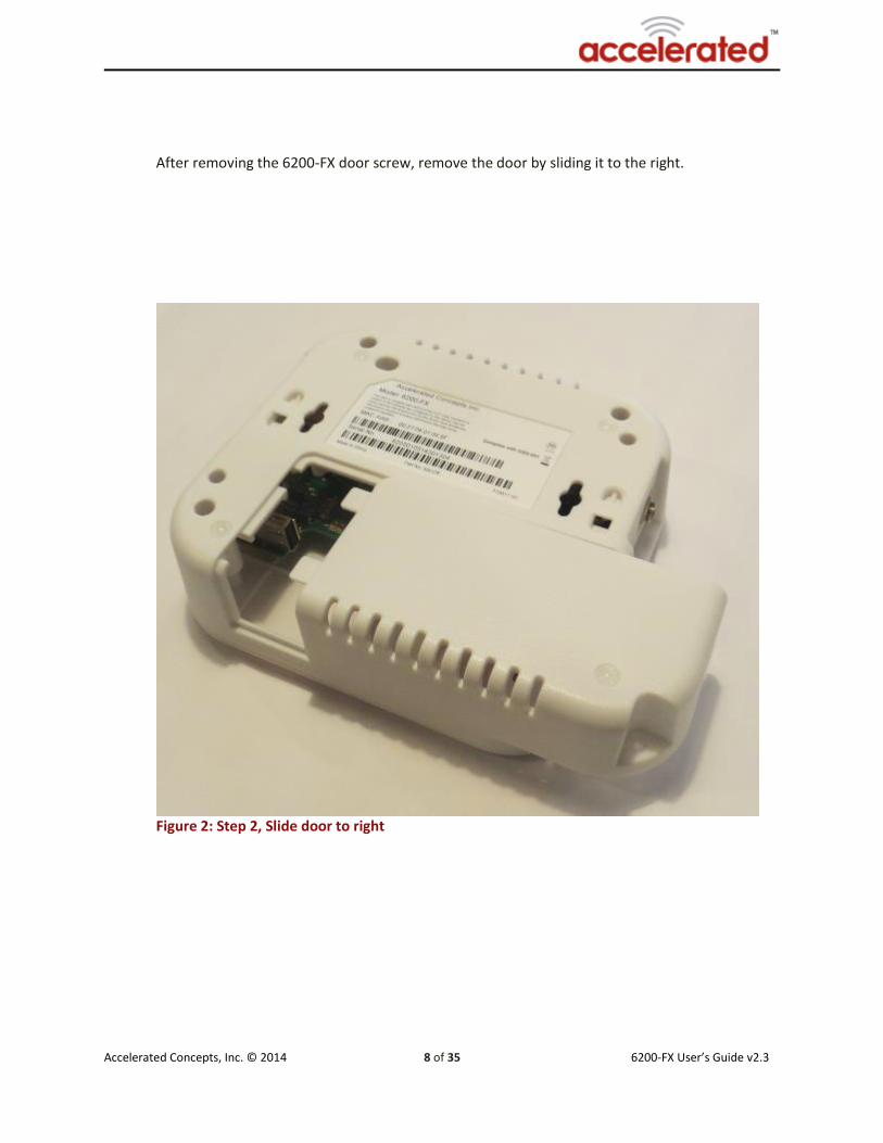
After removing the 6200-FX door screw, remove the door by sliding it to the right.
Figure 2: Step 2, Slide door to right

Accelerated Concepts, Inc. © 2014 9 of 35 6200-FX User’s Guide v2.3
First, insert USB optimizer into 6200-FX device. For the AT&T Beam, fold the USB connector to its open position. Then position USB modem with logo facing downward. Once this is done, twist USB connector that is attached to the AT&T Beam clockwise (turn toward yourself) TWO clicks.
Figure 3
USB Conditioner
CIbd===

Accelerated Concepts, Inc. © 2014 10 of 35 6200-FX User’s Guide v2.3
Insert the USB modem connector into the USB conditioner on the 6200-FX. Replace the door and loosely tighten door screw. IMPORTANT: When inserting AT&T Beam USB device, the logo needs to be facing downward (away from you) as shown in picture (Figure 4).
Figure 4

Accelerated Concepts, Inc. © 2014 11 of 35 6200-FX User’s Guide v2.3
B: Inserting the Cellular Data Card / Modem without USB
Conditioner
Remove the modem cover by loosening the Phillips head screw on the bottom of the case, turning it counter clockwise.
Figure 2: Step 1, Remove Phillips screw

Accelerated Concepts, Inc. © 2014 12 of 35 6200-FX User’s Guide v2.3
After removing the 6200-FX door screw, remove the door by sliding it to the right.
Figure 2: Step 2, Slide door to right

Accelerated Concepts, Inc. © 2014 13 of 35 6200-FX User’s Guide v2.3
Once you have removed the door, insert the modem into the USB port on the inside of the 6200-FX. After modem is installed, replace the door and loosely tighten door screw.
Figure 3: Step 3, insert modem

Accelerated Concepts, Inc. © 2014 14 of 35 6200-FX User’s Guide v2.3
Optimal Placement using Optional Temporary Battery Pack
The 6200-FX comes with a temporary battery pack1 and a built-in Signal Strength Meter. The SSM
is located on the center of the front panel as shown in Figure 1.
Figure 1
1 Please remove temporary battery pack prior to applying another power source.

Accelerated Concepts, Inc. © 2014 15 of 35 6200-FX User’s Guide v2.3
The Signal Strength Meter indicates weak to strong signal strength by lighting a set of
progressing indicators. The more lights, the better the signal. It is important to remove the
battery pack before plugging another source of power into the 6200-FX.
Temporary Battery Pack
6200-FX

Accelerated Concepts, Inc. © 2014 16 of 35 6200-FX User’s Guide v2.3
The LEDs will illuminate and show the current signal strength. Read the current signal strength
by assessing the indicators lit from top to bottom. For Example:
Move the 6200-FX device to all possible locations in the facility, making note of the signal strength
in each location. It is important the device remain stationary for 30 seconds to obtain an accurate
reading of the signal strength for each potential installation location. Continue to investigate
locations to determine optimal placement with maximum signal strength.
Correlation of Signal bars to CSQ and dBm
SIGNAL CSQ dBm Signal Strength Quality
1 0 to 4 -110 to -106 0-11 Bad
2 5 to 9 -105 to -96 12-28 Marginal
3 10 to 14 -95 to -84 29-47 OK
4 15 to 18 -83 to -76 48-60 Good
5 19 to 31 -75 to -50 61-100 Excellent

Accelerated Concepts, Inc. © 2014 17 of 35 6200-FX User’s Guide v2.3
Mounting the 6200-FX
The 6200-FX comes with a variety of mounting options that make it extremely easy to install in an
office or store environment. There are three mounting options for the 6200-FX, traditional screw
mounting, zip tie mount, or ceiling clip mounting.
The unit can be installed using traditional screws. There are two (2) mounting holes in the back
of the unit. Simply insert the screws into the mounting location and slip the 6200-FX over the
screws and seat.
If the unit cannot be mounted using screws due the where it needs to be placed, it can also be
secured using standard zip ties. The 6200-FX has two (2) holes specifically designed to allow zip
ties to be used. Simply slide one end of the zip tie through the guides and attach to any supporting
structure.
Figure 1: Screw mount holes
Figure 2: Zip Tie Guides

Accelerated Concepts, Inc. © 2014 18 of 35 6200-FX User’s Guide v2.3
In some office locations it may be impractical to use wall screws or zip ties. For those locations
the 6200-FX comes with ceiling clips that allow for direct connection to the rails of any standard
dropped ceiling. Two different sized clips are provided for standard and narrow drop ceiling rails.
To attach the clips to the 6200-FX, insert a clip into each of the screw mounting holes (see Figure
1 under “Mounting the 6200-FX”) and twist 1/8 of a turn clockwise until the clip locks securely in
place (do not force or over rotate). After attaching both clips to the 6200-FX, attach the clips to a
drop ceiling rail.
Figure 3: Ceiling Rail Snaps

Accelerated Concepts, Inc. © 2014 19 of 35 6200-FX User’s Guide v2.3
Setting up Remote Power
If remote power is necessary, a Passive Power-Over-Ethernet (PoE) injector is included with every
6200-FX.
Plug the 12V power adapter into the female 2.1mm plug on the Passive PoE injector.
Plug the male RJ-45 Ethernet plug of the Passive PoE injector into the Router or other end device. Plug the female RJ-45 Ethernet plug of the Passive PoE injector into the 6200-FX. The length has been tested to over 300 feet with standard Category 5 cabling.
PoE DC - Red LED that indicates DC Power Adapter is connected to PoE Cable with power.
PoE PWR - Green LED That indicates Cat 5 Ethernet Cable is connected to 6200-FX unit with power.
When both the RED and GREEN lights are illuminated, everything is connected properly.

Accelerated Concepts, Inc. © 2014 20 of 35 6200-FX User’s Guide v2.3
Local Graphical User Interface (GUI)
A web based user interface is available for configuring the Access Point Name (APN) that the 6200-
FX should use to login to the cellular network. It is also used for determining why the radio will
not connect to the cellular network (troubleshooting). Most users will not have a need to enter
the web-based interface on the Accelerated Concepts 6200-FX since the unit comes preloaded
with most carrier APNs. Usage is typically for problem determination and installation only.
To access the webpage go to http://192.168.210.1. Once logged in the following panels will be displayed.
Figure 3: APN Panel

Accelerated Concepts, Inc. © 2014 21 of 35 6200-FX User’s Guide v2.3
Figure 4: Modem Details

Accelerated Concepts, Inc. © 2014 22 of 35 6200-FX User’s Guide v2.3
Figure 5: System Logs
Figure 6: System Info

Accelerated Concepts, Inc. © 2014 23 of 35 6200-FX User’s Guide v2.3
IP Addressing
The Accelerated Concepts 6200-FX can be configured to act as a transparent IP bridge. By
definition this requires that the 6200-FX appear invisible to the network and end device. To
accomplish this task the 6200-FX appears to the cellular carrier as the end device and it appears
as the carrier providing an address via DHCP to the end device. The end device has no need to
know that cellular communication is involved in the connection.
NAT IP Range
This feature allows a 6200-FX to operate in NAT mode. While in this mode, the 6200-FX can be
provided with a specific IP address for the 6200-FX along with a network range for assigning IP
addresses to multiple DHCP clients. Using this feature and an Ethernet Network Hub, the 6200-
FX can assign an IP address to multiple devices at one time.
To use this feature, an IP network address, network prefix, DHCP start IP address, and DHCP end
IP address must be provided in the Accelerated Concepts configuration server for that particular
6200-FX or group of 6200-FXs. An online ipcalc tool can be utilized to help calculate the necessary
values. The Accelerated Concepts configuration parameters associated with these values are:
DRN (DHCP network IP address)
DRP (DHCP network prefix)
DRS (DHCP IP range start)
DRE (DHCP IP range end)
For example, a 6200-FX with the following settings will have a network address of 192.168.10.0/24 and will assign IP addresses from 192.168.10.1 through 192.168.10.254 to the DHCP clients connected to the Ethernet Network Hub:
GIP=192.168.10.1
DRN = 192.168.10.0
DRP = 24
DRS = 192.168.10.1
DRE = 192.168.10.254

Accelerated Concepts, Inc. © 2014 24 of 35 6200-FX User’s Guide v2.3
Required Network Access for 6200-FX General Connectivity
The following IP addresses or domains need to be available to the 6200-FX through its WAN
cellular connection in order for the device to function properly and provide a plug-n-play
connection.
IP Address Ports Needed Domain Name (details)
108.166.125.69 123 Time1.accnscom (time server)
71.100.234.61 123 time2.accns.com (backup time
server)
50.28.67.96 123 (backup time server)
108.33.27.70 80/443/10443/11443 configuration.accns.com
(Accelerated View server -
config/firmware/certificates)
108.33.27.72 514 logs.accns.com (syslog server)
108.166.111.162 514 syslog.accns.com (backup syslog
server)
184.106.213.137 500/4500 remote.accns.com (IPSEC
remote control server)
8.8.8.8 (ping testing - although this can
be substituted)

Accelerated Concepts, Inc. © 2014 25 of 35 6200-FX User’s Guide v2.3
6200-FX Specifications
Technical Specifications
Ethernet: 1 Ethernet port 10/100 BASE-T (RJ-45)
Cellular USB Modem ports: USB 2.0 1 Internal; 1 External. Theoretical speed up to
480mbps
Cellular Compatibility: LTE, HSPA+, HSPA21, HSPA42, EVDO
Passive PoE: Passive PoE (remote power up to 300’) using the
included injector cable
Power supply: 12V DC, 1.5A; 100–240 AC
LEDs: USB Modem, Signal Strength and 2G / 3G / 4G LTE
Dimensions: 5.75 x 5.25 x 1.75 inches
Weight: 8.5 ounces
Temperature: 32°F to 122°F operating
Certifications: FCC Part 15 Class B
Technology: EVDO, LTE/HSPA+ modem backwards compatible to
GSM/GPRS/EDGE or 1xRTT Downlink Rates: LTE 100 Mbps, HSPA+ 21.1 Mbps (theoretical) Uplink Rates: LTE 50 Mbps, HSPA+ 5.76 Mbps (theoretical) Frequency Band: Dependent on Radio/Geography (no limitations)

Accelerated Concepts, Inc. © 2014 26 of 35 6200-FX User’s Guide v2.3
Appendix A: Sprint
The NetGear 341U modem provided by Sprint has its own local web interface that provides
additional information and features specific to the 341U modem, including the ability to update
the 341U's software version, roaming settings, and usage info. To access the 341U's local
interface, first navigate to the 6200-FX's local web interface at http://192.168.210.1 (see “Local
Graphical User Interface (GUI) section of this guide). Next, click on the "Modem Details" tab on
the navigation bar on the left, and click the URL link in the "Admin Interface" column in the
modem details.
Figure 1: Local web interface

Accelerated Concepts, Inc. © 2014 27 of 35 6200-FX User’s Guide v2.3
Figure 2: Modem Details

Accelerated Concepts, Inc. © 2014 28 of 35 6200-FX User’s Guide v2.3
Figure 3: Sprint web interface

Accelerated Concepts, Inc. © 2014 29 of 35 6200-FX User’s Guide v2.3
Appendix B: Configuring Special APN
If you need to configure a special APN for your 6200-FX:
Power the 6200-FX on with no USB modem, aircard, or any other device connected to the 6200-FX's internal or external USB ports.
Connect an Ethernet cable between the 6200-FX and a laptop or PC.
Power the 6200-FX on. Once the 6200-FX boots up and assigns an IP address to your computer, open a web browser and navigate to '192.168.210.1''
Enter in the APN credentials required for your USB modem or aircard to connect. In the example below, the APN 'wbb.business.net' is being utilized. APN: wbb.business.net Username: secureuser Password: secret
Click 'Save' to save the APN into the 6200-FX.
Power off the 6200-FX.
Connect the USB modem or aircard into either the internal or external port of the 6200-FX.
Power the 6200-FX on.
Figure 7: Special APN Panel
Once the 6200-FX boots up, it will try to connect using the specified APN with the USB modem.
Once the 6200-FX establishes a network connection (signified by the USB LED illuminating blue
and 3G LED illuminating either green or blue), the 6200-FX will check its configuration on the
6200-FX portal, save any specified APN configurations, and restart once to apply any new
configuration settings.

Accelerated Concepts, Inc. © 2014 30 of 35 6200-FX User’s Guide v2.3
Appendix C: Real-Time Management
Below are details for all the commands that can be sent to a 6200-FX device, along with details
as to what each command does.
Remote Control
Check status - the 6200-FX will immediately send its current status.
Check signal strength - the 6200-FX will send its signal strength and network info once every 10 seconds for the next 15 minutes.
Perform Speed Test - the 6200-FX will perform a speed test and send the Upload/Download results.
ARPing Attached Device - the 6200-FX will attempt to ARPing the client device attached to its Ethernet port.
Send Wake-on-LAN to Attached Device - the 6200-FX will sent a wake-on-LAN packet to the client device attached to its Ethernet port.
Check Configuration - the 6200-FX will immediately pull its configuration and reboot to apply any new settings.
Reboot - reboot the 6200-FX.
SMS
Set Configuration - a popup window appears where a user can enter in a configuration option or set of options to apply to the 6200-FX. Multiple config options must be separated by a comma. For example, if a user wants to set the APN of a 6200-FX to managedvpn, they would enter "modem_apn=managedvpn".
Configuration Reset - restore default configuration on the 6200-FX and reboot.
Firmware Reset - restore to backup firmware image on the 6200-FX, and reboot.
Factory Reset - restore default configuration on the 6200-FX, restore to backup firmware image, and reboot.
Remote Control - tell the 6200-FX to bring up its remote control tunnel (useful if on low data plan, so the remote control tunnel is not always up using data).
Reboot - reboot the 6200-FX.

Accelerated Concepts, Inc. © 2014 31 of 35 6200-FX User’s Guide v2.3
Appendix D: Connecting a Remote Power Unit
Power off the 6200-FX and the NP-02U RemotePower devices.
Connect a serial-to-USB cable between the 6200-FX's open USB port and the Remote Power's serial RJ-45 port.
Ensure that the Remote Power device has its own power source. Failure to do so may cause damage to the serial-to-USB cable.
Power on the Remote Power device
Power on the 6200-FX.

Accelerated Concepts, Inc. © 2014 32 of 35 6200-FX User’s Guide v2.3
Appendix E: Connecting a Meraki MX60 Router
The Meraki MX60 router should act as the DHCP server in this setup; the 6200-FX is simply the
WAN connection for the MX60.
Start by first connecting the 6200-FX to the WAN/Internet port of the Meraki MX60.
Wait for the MX60 device to verify that it has a valid Internet connection. This is reflected
by the WAN Connectivity LED on the MX60 (the light just to the right of the power LED)
illuminating solid green.
Navigate to the web UI of the MX60, which can be done either through the Internet WAN
access, or by connecting a laptop/PC to one of the MX60's LAN ports.
Ensure that the "Client addressing" configuration option is set to "Run a DHCP server". This
enables the DHCP on the MX60. Refer to the first screenshot below to see where this
configuration option is located.
If a bridge or switch device is being utilized in the LAN network of the MX60 (ex. a wireless
bridge device is connected to the MX60's LAN port to provide wireless connectivity), then
ensure that the "Client tracking" configuration option under "Addressing and VLANs" is set
to "Track clients by IP address". Refer to the second screenshot below to see where this
configuration option is located.
Screen Shot 1

Accelerated Concepts, Inc. © 2014 33 of 35 6200-FX User’s Guide v2.3
Screen Shot 2

Accelerated Concepts, Inc. © 2014 34 of 35 6200-FX User’s Guide v2.3
Support
Technical Support
If there are any problems installing any of our products and you require technical assistance,
please call or email our help desk.
+1 (813) 699-3110
Support hours are 9:00am to 5:00pm GMT – 5

Accelerated Concepts, Inc. © 2014 35 of 35 6200-FX User’s Guide v2.3
Copyright © 2014 by Accelerated Concepts, Inc. All rights reserved.