Embed Size (px)
Citation preview

Acano solution
Acano Server & VM Release R1.8Single Combined Server Deployment Guide
March 2016
76-1054-02-K

76-1054-02-K: Single Combined Acano Server Deployments R1.8 2
Contents
1 Introduction 6
1.1 How to Use this Guide 6
1.1.1 Commands 8
1.1.2 Management and network interfaces 9
1.2 Application Programming Interface 9
2 General Concepts for Deployment 11
2.1 Call Bridge 12
2.2 Web Bridge 12
2.2.1 Customization 12
2.3 TURN Server 13
2.4 XMPP server 13
2.4.1 Deploying Acano clients 14
2.5 Database 15
2.6 H323 Gateway 15
2.7 SIP trunks and routing 16
2.8 Support for Lync clients 16
2.9 Diagnostics and Troubleshooting 17
3 Prerequisites 18
3.1 Prerequisites 18
3.1.1 DNS configuration 18
3.1.2 Security certificates 18
3.1.3 Firewall configuration 18
3.1.4 Syslog server 18
3.1.5 Network Time Protocol Server 19
3.1.6 Call Detail Record Support 20
3.1.7 Host name 20
3.1.8 Other requirements 21
3.1.9 Acano X series server-specific prerequisites 21
3.1.10 Virtualized deployment-specific prerequisites 22
4 Configuring the MMP 23
4.1 Creating and Managing MMP and Web Admin Interface User Accounts 23
4.2 Upgrading Software 23
4.3 Configuring the Web Admin Interface for HTTPS Access 24

76-1054-02-K: Single Combined Acano Server Deployments R1.8 3
4.4 Configuring the Call Bridge 25
4.5 Configuring the XMPP server 26
4.5.1 Configuring XMPP multi-domains 27
4.6 Configuring the Web Bridge 28
4.7 Configuring the TURN Server 30
5 LDAP Configuration 34
5.1 Why use LDAP? 34
5.2 Acano Server Settings 34
5.3 Example 38
6 Dial Plan Configuration – SIP Endpoints 40
6.1 Introduction 40
6.2 SIP Endpoints Dialing a Call on the Acano Server 41
6.2.1 SIP call control configuration 42
6.2.2 VCS search rule configuration 43
6.2.3 Creating a space on the Acano server 43
6.2.4 Adding a dial plan rule on the Acano server 44
6.3 Media Encryption for SIP Calls 44
6.4 Enabling TIP Support 44
6.5 IVR Configuration 45
7 Dial Plan Configuration – Integrating Lync 47
7.1 Lync Clients Dialing into a Call on the Acano server 47
7.1.1 Lync Front End Server configuration 47
7.1.2 Adding a dial plan rule on the Acano server 47
7.2 Integrating SIP Endpoints and Lync Clients 48
7.3 Web Admin Interface Configuration Pages that Handle Calls 49
7.3.1 Outbound Calls page 49
7.3.2 Incoming Call page: call matching 50
7.3.3 Call forwarding 51
7.4 Adding Calls between Lync Clients and SIP Video Endpoints 51
7.4.1 Lync Front End Server configuration 52
7.4.2 VCS configuration 52
7.4.3 Acano server configuration 53
7.5 Integrating Acano Clients with SIP and Lync Clients 53
7.6 Lync Edge Server Integration 54
7.6.1 Lync Edge Call Flow 54
76-1054-02-K: Single Combined Acano Server Deployments R1.8 4
7.6.2 Configuration for using Lync Edge 56
7.7 Lync Federation 57
7.8 Calling into scheduled Lync meetings directly and via IVR 58
8 SIP and Lync call traversal of local firewalls 61
8.1 Configuring SIP/Lync call traversal 63
9 Web Admin Interface Settings for XMPP 66
9.1 Network Topology 66
9.2 XMPP Settings 67
9.3 Client-based space Creation and Editing 68
10 Web Admin Interface Settings for the Web Bridge 70
10.1 Network Topology 70
10.1.1 Web Bridge Call Flow 71
10.2 Web Bridge Settings 73
11 Web Admin Interface Settings for the TURN Server 76
11.1 Network Topology 76
11.2 TURN Server Settings 77
12 Additional Security Considerations & QoS 78
12.1 Common Access Card (CAC) integration 78
12.2 Online Certificate Status Protocol (OCSP) 78
12.3 FIPS 78
12.4 TLS Certificate Verification 79
12.5 User Controls 79
12.6 Firewall Rules 79
12.7 DSCP 80
Appendix A DNS Records Needed for the Deployment 81
Appendix B Ports Required for the Deployment 83
Appendix C Example of Configuring a Static Route from a Lync Front EndServer 86
C.1 Lync Configuration Changes 86
C.2 Acano Server Configuration 87
Appendix D More Information on LDAP Field Mappings 89

76-1054-02-K: Single Combined Acano Server Deployments R1.8 5
Appendix E Using a standby Acano server 91
E.1 Backing Up the Currently Used Configuration 91
E.2 Transferring a Backup to the Standby Server 91
E.3 Time for Swapping Servers 93
Figures:
Figure 1: Single combined server deployment 6
Figure 2: Overview of guides covering the Acano solution 8
Figure 3: Example of an Acano solution using an Acano X series server in a singlecombined server deployment 11
Figure 4: TURN server supporting TCP and UDP 13
Figure 5: Example Call flow diagram 14
Figure 6: TURN server public IP address 31
Figure 7: Example deployment for dial plan configuration 41
Figure 8: Example of SIP video endpoints calling into Acano server hosted calls 42
Figure 9: Example Lync clients calling into Acano server hosted meetings 47
Figure 10: Example of SIP video endpoints and Lync clients calling into Acanoserver hosted meetings 48
Figure 11: Example of SIP video endpoints and Lync clients in calls 52
Figure 12: Call Bridge to Lync Edge Server Call Flow 55
Figure 13: Firewall traversal for remote SIP devices using the SIP Edge component 62
Figure 14: Example network topology showing XMPP server 66
Figure 15: Example network topology showing Web Bridge 70
Figure 16: WebRTC Client port usage 71
Figure 17: Example network topology showing TURN Server 76
Figure 18: Ports that must be open in a single combined server deployment 83

1 Introduction
76-1054-02-K: Single Combined Acano Server Deployments R1.8 6
1 Introduction
Note: coSpace has been renamed space. This document has been changed to usingspace, except where it refers to coSpace API objects.
This guide covers the Acano server deployed as a single combined server deployment.This deployment has no scalability or resilience. The server comprises a number ofcomponents, see Figure 1.
Figure 1: Single combined server deployment
Not all of these components need to be configured, you only need to configure thecomponents that are appropriate to your deployment. This is discussed in Chapter 2.
The server can be an Acano X3 or X2 server, or be hosted on a virtual host (VM) ; theterm “Acano server” in this document covers both.
Note: From release 1.7, the Acano server includes an H.323 Gateway. The gateway isdesigned to be used only with the Acano Call Bridge. See the H.323 GatewayDeployment Guide for more information.
1.1 How to Use this Guide
This guide follows on from the X series and VM server Installation Guides (see thefigure below)—and assumes that you have completed the instructions there already.

1 Introduction
76-1054-02-K: Single Combined Acano Server Deployments R1.8 7
Certificate information has been moved from this guide to the "Certificate Guidelinesfor Single Combined deployments", consequently the two guides (this one and theCertificate Guidelines) should be read and used together.
In addition to this deployment guide and the Certificate Guidelines, the referencematerial shown in the figure below can be found at the Acano Documentation &software page. If you need any technical assistance with the configuration, or youwant to report a suspected bug, email [email protected].

1 Introduction
76-1054-02-K: Single Combined Acano Server Deployments R1.8 8
Figure 2: Overview of guides covering the Acano solution
1.1.1 Commands
In this document, commands are shown in black and must be entered as given—replacing any parameters in <> brackets with your appropriate values. Examples are
1 Introduction
76-1054-02-K: Single Combined Acano Server Deployments R1.8 9
shown in blue and must be adapted to your deployment.
1.1.2 Management and network interfaces
There are two layers to the Acano server: a Platform and an Application.
n The Platform is configured through the Mainboard Management Processor (MMP).The MMP is used for low level bootstrapping, and configuration via its commandline interface.
Note: On the Acano X series servers the MMP can be accessed via the serial Consoleport or using SSH on the Ethernet interface labeled Admin. In the virtualizeddeployment the MMP is accessed on virtual interface A.
n The Application runs on this managed platform with configuration interfaces of itsown. The application level administration (call and media management) is done viaeither the Call Bridge’s Web Admin Interface, or through the API. Either can beconfigured to run on any one of the Ethernet interfaces.
On the Acano X series servers there are five physical Ethernet interfaces labeledAdmin, A, B C and D. In the virtualized deployment one Ethernet interface (A) iscreated but up to three more can be added (B, C and D).
Note: There is no physical separation between the media interfaces A-D on an Xseries server but the Admin interface is physically separate. Each interface isconfigured independently at the IP level. IP forwarding is not enabled in either theAdmin or host IP stack.
See the appropriate (Acano X series or virtualized deployment) Installation Guide fordetails.
1.2 Application Programming Interface
The Acano server supports an Application Programming Interface (API). The API usesHTTPS as a transport mechanism and is designed to be scalable in order to managethe potentially very large numbers of active calls and spaces available in the Acanosolution.
The API includes LDAP server access methods for adding, configuring and modifyingLDAP servers, and support for multi-tenancy for searching calls through an additionalTenant ID. Other additions include posting to space message boards, the ability tofilter the set of active call legs to just those experiencing "alarm" conditions (forexample, packet loss or excessive jitter) and the ability to retrieve system-wide statusvalues.

1 Introduction
76-1054-02-K: Single Combined Acano Server Deployments R1.8 10
Multi-tenancy means that groups of users can be entirely segmented within thesolution as required by service provider deployments e.g. users will only be able tomeet, assign users to spaces, and search in the directory within the same configuredcustomer groups.
Refer to the Acano API Reference guide for more details.

2 General Concepts for Deployment
76-1054-02-K: Single Combined Acano Server Deployments R1.8 11
2 General Concepts for DeploymentThis chapter provides an overview of the general concepts for deploying an Acanoserver in a single combined server deployment. The server can be either a X series or aVM deployment. Figure 1 illustrates a typical deployment.
Note: From release 1.7, the Acano server includes an H.323 Gateway. The gateway isdesigned to be used only with the Acano Call Bridge. Other than a brief summary inSection 2.6 this guide does not cover the H.323 Gateway, instead see the H.323Gateway Deployment Guide for more information.
Figure 3: Example of an Acano solution using an Acano X series server in a single combined serverdeployment

2 General Concepts for Deployment
76-1054-02-K: Single Combined Acano Server Deployments R1.8 12
2.1 Call Bridge
The Call Bridge is the component on the Acano server that bridges the conferenceconnections, enabling multiple participants to join meetings hosted on the Acanoservers or Lync AVMCUs. The Call Bridge exchanges audio and video streams so thatparticipants can see and hear each other.
The Call Bridge requires an activation key to operate fully. X series servers have a pre-installed activation key for the Call Bridge, you do not need to do anything further.
A Call Bridge enabled on an Acano VM server requires an activation key; otherwise youwill only be able to create a few calls simultaneously. The key is associated with theMAC address of your virtual server. Follow the steps in the Acano solution VirtualizedDeployment Installation Guide to obtain and apply the activation key.
2.2 Web Bridge
If you are using the Acano WebRTC Client you will need to enable and configure theWeb Bridge, refer to the sections Configuring the Web Bridge and Web AdminInterface Settings for the Web Bridge . The Acano WebRTC Client works on HTML5-compliant browsers and uses the WebRTC standard for video and audio. For a list oftested browsers see the Acano FAQ here. Using the Web Bridge does not require anactivation key, but it does require an enabled Call Bridge. If you wish to customize theexperience when users join a meeting, then depending on the level of customizationrequired, you may need to purchase a branding key.
2.2.1 Customization
The background image and logo on the landing page for the WebRTC Client can becustomized via the Web Admin interface; go to Configuration>General and in the WebBridge settings section provide the URIs for the custom background image and customlogo. For information on file sizes, formats and image proportions refer to theCustomization Guidelines.
Other features can also be customized through the API, for example:
n the colors for the Join pane on the WebRTC Client landing page,
n IVR messages,
n SIP/Lync call messages,
n text shown in invitations to join conferences.
These require a branding key, contact your partner for details on how to acquire a keyappropriate to your required level of branding. See the Customization Guidelines forexamples on using the API to undertake this level of customization.

2 General Concepts for Deployment
76-1054-02-K: Single Combined Acano Server Deployments R1.8 13
2.3 TURN Server
The TURN server provides firewall traversal technology, allowing the Acano server tobe deployed behind a Firewall or NAT. To connect to the deployment from externalAcano clients or SIP endpoints you need to enable the TURN server, refer to thesections on Configuring the TURN Server and Web Admin Interface Settings for theTURN Server. If you are using Acano clients you also need to configure the Web Admininterface to allow the Call Bridge and external clients to access the TURN server. Using the TURN server does not require an activation key.
Media sent over TCP is encrypted using TLS. From release 1.8, the TURN serversupports TCP to UDP interworking (see Figure 4). A browser can send TCP media tothe TURN server which converts it to standard UDP media. This is useful when UDPtraffic from browsers is blocked.
Figure 4: TURN server supporting TCP and UDP
2.4 XMPP server
The XMPP server handles the media to and from Acano clients, including the Web RTCclient, and requires an activation key. X series servers have the activation key pre-installed, providing you specified using the Acano clients at the time of purchase. Youneed to apply an XMPP activation key to a VM server deployment. If you did notreceive an XMPP activation key as part of your capacity or user license, contact yourreseller with the MAC address of one of the interfaces assigned to your VM. The keywill be tied to that MAC address and cannot be moved from server to server.
If you are NOT planning to use the Acano PC Client, iOS Client for iPhone and iPad,Mac Client or WebRTC Client you do not need to enable the XMPP server or apply theactivation key, disregard all sections referring to the XMPP server.

2 General Concepts for Deployment
76-1054-02-K: Single Combined Acano Server Deployments R1.8 14
2.4.1 Deploying Acano clients
Note: Acano clients are now referred to as Acano apps in the user documentation.
If you are using any of the Acano clients you need to enable the XMPP server, refer tothe sections on Configuring the XMPP server and Web Admin Interface Settings forXMPP.
The following diagram shows example control and media flows during an Acano clientcall.
Figure 5: Example Call flow diagram
Points to note on the figure above:

2 General Concepts for Deployment
76-1054-02-K: Single Combined Acano Server Deployments R1.8 15
n The following ports must be open:UDP Port 3478 or TCP Port 443* from Call Bridge to TURN server (for TURN)UDP Port 50000-51000** from Call Bridge to TURN server (for media)TCP Port 443 (HTTPS) from Call Bridge to Web Bridge (for guest login)
* If you use Port 443 for both the Web Bridge and the TURN server then they mustbe on different interfaces of the server. Alternatively chose a different port for theTURN server, see Chapter 1.** Although the range between the TURN server and the external Acano clients isshown as 50000-51000, future releases may require a wider range of 32768-65535.
n Internal clients connect directly to the XMPP server on port 5222 and mediaconnects directly between the Acano client and the Call Bridge.
n External Acano clients establish a control connection to the XMPP server (blackline). Media can go directly from the Acano client to the Call Bridge (dashed blueline) or be relayed via the TURN server if required (blue line).
n Another deployment option is to enable the XMPP server on a second interface andconnect that interface to the private network. Then internal clients can connectdirectly to the XMPP server. Separate internal and external SRV records for theXMPP service need to be configured, directed to the two interfaces that the XMPPserver is listening on.
n Both internal and external Acano clients use ICE/TURN to find suitable candidatesfor connectivity and choose the best: in the case of internal clients this will alwaysbe the local host candidates on the internal network.
2.5 Database
The Call Bridge reads from and writes to the database storing the space information,for example the members of spaces, chat messages occuring between members of aspace, recent activity within a space.
In a single combined deployment the database is created and managed automaticallyby the Call Bridge and does not require an activation key or being enabled.
2.6 H323 Gateway
The Acano H.323 Gateway enables an H.323 call to connect to the Acano Call Bridge.The H.323 Gateway does not provide firewall traversal or call control, you arerecommended to deploy a H.323 Gatekeeper to perform these functions. With theH.323 Gateway enabled, you can now make the following calls:
H.323 call > H.323 GW > space

2 General Concepts for Deployment
76-1054-02-K: Single Combined Acano Server Deployments R1.8 16
H.323 call > H.323 GW > Call Bridge->Lync
H.323 call > H.323 GW > Call Bridge->SIP device
H.323 call > H.323 GW > Call Bridge->Acano client
The H323 Gateway can be enabled on the same server as the Call Bridge or on aseparate one. Note: by default the H.323 Gateway uses port 6061.
Refer to the H.323 Gateway deployment guide for more information.
2.7 SIP trunks and routing
SIP trunks need to be set up to the Acano server from one or more of the following: SIPCall Control, Voice Call Control and Lync Front End (FE) server. Changes to the callrouting configuration on these devices are required to route calls to the Acano serverthat require the XMPP service or Web Bridge service for interoperability.
From R1.8, the Acano Server supports SIP and Lync call traversal of local firewalls, thisis a beta feature and should not be used in production environments. For moreinformation see Chapter 8.
2.8 Support for Lync clients
You can use both Lync 2010 and 2013 clients connected to a Lync 2010 or 2013 serveror a Skype for Business server.
The Acano server uses:
n the RTV codec transcoding up to 1080p with the 2010 Lync Windows client and 2011Lync Mac clients,
n the H.264 codec with the 2013 Lync Windows client and Skype for Business client.
The Acano server will provide both RTV and H.264 streams when a mixture of clientsversions are connected.
Lync 2010 and 2013 clients and Skype for Business clients can share content. TheAcano server transcodes the content from native Lync RDP into the video format usedby other participants in the meeting and sends it as a separate stream. Lync andSkype for Business clients also receive content over a RDP stream and can display itseparately from the main video.
The Lync FE Server will need a Trusted SIP Trunk configured to route calls originatingfrom Lync endpoints through to the SIP video endpoints i.e. to route calls withdestination in the SIP video endpoint domain through to the Call Bridge.
The SIP Call Control will require configuration changes to route calls destined to theLync/Skype for Business client domain to the Call Bridge so that SIP video endpointscan call Lync/Skype for Business clients.

2 General Concepts for Deployment
76-1054-02-K: Single Combined Acano Server Deployments R1.8 17
The dial plan routes Lync/Skype for Business calls between these two domains in bothdirections.
The Acano server includes support for Lync Edge to enable Lync/Skype for Businessclients outside of your firewall to join spaces.
From R1.8, the new dual homed conferencing functionality improves how the Acanoserver communicates with the Lync AVMCU, resulting in a richer meeting experiencefor both Lync/Skype for Business and Acano users.
If you already have an on-prem Lync deployment or Lync Federation deploymentworking with the Acano server deployment, then no additional configuration isrequired on the Acano server. If this is a new deployment, then make sure that youconfigure the Lync Edge settings on the Acano server, see Section 7.6.
For information on the features in R1.8 which improves the experience of participantsin Lync/Skype for Business meetings, see:
n FAQ on the improvements in meeting experience for Lync participants,
n FAQ on dual homed conferencing,
n FAQ on RDP support,
n FAQ on multiple video encoder support.
2.9 Diagnostics and Troubleshooting
In addition to using a Syslog server it is also possible to enable additional SIP tracingusing the Logs > Call Diagnostics page in the Web Admin Interface. These logs may beuseful when investigating call setup failure issues for SIP endpoints and should bedisabled at all other times. To prevent the verbose logging being enabled for longerthan necessary, it automatically shuts off after a choice of 1 minute, 10 minutes or 30minutes. Refer to the Acano Support FAQs on the Acano website for moretroubleshooting information.

3 Prerequisites
76-1054-02-K: Single Combined Acano Server Deployments R1.8 18
3 Prerequisites
3.1 Prerequisites
This chapter describes the changes to your network configuration that you need toconsider before installing and configuring the Acano server; some of these items can beconfigured beforehand.
3.1.1 DNS configuration
The Acano server needs a number of DNS SRV and A records. See Appendix A for a fulllist, but specific records are also mentioned elsewhere.
3.1.2 Security certificates
You will need to generate and install X.509 certificates and keys for Acano serviceswhich use TLS; for example, Call Bridge, Web Admin Interface (the Call Bridge’sinterface), Web Bridge, TURN server, and the XMPP server.
The Certificates Guidelines for single combined deployments contains bothbackground information on certificates and instructions, including how to generateself-signed certificates using the Acano server’s MMP commands. These certificatesare useful for testing your configuration in the lab. However, in a productionenvironment we strongly recommend using certificates signed by a CertificateAuthority (CA).
Instructions that were previously in this guide concerning certificates have beenremoved and replaced by a single step referencing the Certificate Guidelines.
Note: If you self-sign a certificate, and use it, you may see a warning message that theservice is untrusted. To avoid these messages re-issue the certificate and have it signedby a trusted CA: this can be an internal CA unless you want public access to thiscomponent.
3.1.3 Firewall configuration
See Appendix B for the list of ports which need to be opened on your firewall andSection 12.6 for advice on creating Firewall rules.
3.1.4 Syslog server
The Acano server creates Syslog records which are stored locally and can also be sentto a remote location. These records are useful when troubleshooting because they

3 Prerequisites
76-1054-02-K: Single Combined Acano Server Deployments R1.8 19
contain more detailed logging than is available on an Acano server’s own internal logpage. Internal syslog messages can be downloaded over SFTP, however Acanorecommends that the host server is configured to send debug information to a remoteSyslog server.
Note: The Syslog server must use TCP not UDP. Check that your Syslog server isconfigured to use TCP.
Follow the instructions below to define a Syslog server.
1. SSH into the MMP and log in.
2. Enter the following command, syslog server add <server address> [port]
Examples:
syslog server add syslog01.example.com 514syslog server add 192.168.3.4 514
3. Enable the Syslog server by entering:
syslog enable
4. Optionally, if you want to send the audit log to a Syslog server follow these steps.
(The audit log facility records configuration changes and significant low-levelevents. For example, changes made to the dial plan or configuration of a space viathe Web Admin Interface or the API, are tracked in this log file, and tagged with thename of the user that made the change. The file is also available via SFTP.)
a. Create a user with the audit role.
user add <username> (admin|crypto|audit|appadmin)user add audituser audit
b. Log out of the MMP and log back in with the newly created user account.
c. Enter the command (this command can only be run by a user with the auditrole):syslog audit add <servername>syslog audit add audit-server.example.org
Note: Normally local Syslog files are overwritten in time, but you can permanentlystore system and audit log files using the syslog rotate <filename> and syslogaudit rotate <filename> commands. These files can also be downloaded overSFTP. See the MMP Command Reference.
3.1.5 Network Time Protocol Server
Configure a Network Time Protocol (NTP) server to synchronize time between theAcano components.

3 Prerequisites
76-1054-02-K: Single Combined Acano Server Deployments R1.8 20
Note: Sharing a common view of time is important for multiple reasons, it is necessaryfor the check for certificate validity and to prevent replay attacks.
1. If necessary, SSH into the MMP and log in.
2. To set up an NTP server, type:
ntp server add <domain name or IP address of NTP server>
To find the status of configured NTP servers, type ntp status
See the MMP command reference for a full list of ntp commands.
3.1.6 Call Detail Record Support
The Acano server generates Call Detail Records (CDRs) internally for key call-relatedevents, such as a new SIP connection arriving at the server, or a call being activated ordeactivated. It can be configured to send these CDRs to a remote system to becollected and analyzed. There is no provision for records to be stored on a long-termbasis on the Acano server, nor any way to browse CDRs on the Acano server.
From R1.8, the Acano server supports up to two CDR receivers, enabling you to deploytwo different management tools or two instances of the same management tool forresiliency. If you are using Acano Manager, the Acano Manager server must be one ofyour CDR receivers, you can either add a second Acano Manager server or add adifferent management platform.
You can use either the Web Admin Interface or the API to configure the Acano serverwith the URI of the CDR receivers. If you are using the Web Admin interface go toConfiguration>CDR settings and enter the URI of the CDR receivers. Refer to theAcano solution Call Detail Records Guide or the API Reference guide for details onusing the API to configure the Acano server with the URIs of the CDR receivers.
3.1.7 Host name
Acano recommends that the Acano server is given its own hostname.
1. If necessary, SSH into the MMP and log in.
2. Type:hostname <name>hostname london1hostname mybox.example.com
3. Type:reboot
Note: A reboot is required after issuing this command.
3 Prerequisites
76-1054-02-K: Single Combined Acano Server Deployments R1.8 21
3.1.8 Other requirements
n Access to an LDAP server to import users. This can be a Microsoft Active Directory(AD) server or an OpenLDAP server.
If you plan for users to utilise the Acano clients to connect to the Acano system,then you must have an LDAP server. User accounts are imported from the LDAPserver. You can create user names by importing fields from LDAP as described inLDAP Configuration. The passwords are not cached on the Acano server, they aremanaged centrally and securely on the LDAP server. When an Acano clientauthenticates, a call is made to the LDAP server.
n Decision on a dial plan to use to reach calls hosted on the Call Bridge. The dial planwill depend on your environment; that is whether you are making one or more of thefollowing types of call: Lync, SIP (including voice) or Acano client calls. Instructionsfor deploying this dial plan are given in Chapter 6.
n Access to one or more of the following to test the solution: Lync clients, SIPendpoints, SIP phones and/or Acano clients as appropriate.
n Access to a SIP Call Control platform if you intend to make SIP calls (for example,using Cisco VCS) to make dial plan configuration changes. The changes required toset up these SIP trunks (e.g. resilient trunks from a device such as Cisco VCS intoone or more Call Bridges) are given in this document.
Note: Information on setting up the SIP Trunk to a Cisco Unified CommunicationsManager (CUCM), the Avaya CM and Polycom DMA has been removed fromappendices in this version of the Deployment guide. The information is now in a newThird Party Call Control Guide available on acano.com/support.You can use othercall control devices not listed in the Third Party Call Control Guide.
n If you intend to integrate the Acano server with an audio deployment, the Acanoserver must connect to a Voice Call Control device attached to a PBX; it is notpossible to connect an Acano server directly to a PBX.
n If deploying in a Lync environment, access to the Lync Front End (FE) server tomake dial plan configuration changes there. The changes required are given in thisdocument.
3.1.9 Acano X series server-specific prerequisites
n A suitable environment: refer to the Hardware/Environmental Data Sheet fordetails on the required power and cooling
n The Acano X series server has two power modules, and country-specific powercables are supplied for the AC power supplies. The server will work with just a single

3 Prerequisites
76-1054-02-K: Single Combined Acano Server Deployments R1.8 22
power unit connected. To implement power supply redundancy you must connectboth modules to power supplies. Connecting the modules to independent powersupplies allows for the greatest resiliency.
n 2U of rack space if using the rack mounting kit; 3U of rack space if installing on ashelf
n A minimum of two Ethernet links:
l One for the MMP (labeled Admin on the back of the Acano X series server). Thespeed can be 100M or 1G.
l One for a media interface (there are four labeled A to D). The speed can be 1Gor10G.
IP addresses can be configured statically or automatically via DHCP orSLAAC/DHCPv6. Ethernet links will operate at the speed of the network switch; theswitch port should be set to auto negotiate speed. If you are using a speed of 10G besure to use the appropriate cable.
See the Installation Guide for the X series Server for full details.
Note: The activation key for the XMPP server is pre-installed on Acano Servers (X1, X2and X3).
3.1.10 Virtualized deployment-specific prerequisites
n A qualified host server with some specific resources. See the Installation Guide forthe Virtualized Deployment for full details.
n If you plan to deploy Acano clients including the WebRTC client you will need toapply an activation key for the XMPP server. See Section 2.4 for more information.

4 Configuring the MMP
76-1054-02-K: Single Combined Acano Server Deployments R1.8 23
4 Configuring the MMPThe Acano server components are configured using the MMP.
4.1 Creating and Managing MMP and Web Admin Interface UserAccounts
You should have created an MMP administrator user account by following the AcanoX series Server Installation Guide or the Acano VM Installation Guide according to yourdeployment; if so, go on to the next section. The same account is used to access theWeb Admin Interface.
(If you do not have these MMP administrator user accounts, you will have to use theemergency admin recovery procedure detailed in the Installation Guide appropriate toyour deployment.)
Note: See the Acano solution MMP Command Reference Guide for the full range ofMMP commands, including setting up additional administrator user accounts and useraccounts with other roles.
4.2 Upgrading Software
The Acano X series servers ship with the latest release available at the time ofshipment but may not be up-to-date. Equally, if you downloaded the OVF ZIP file forthe virtualized deployment some days ago, we advise you to check on the partnersection of the Acano website whether a later version is available, and if so, upgradebefore you start testing. The following instructions apply to both types of deployment:
1. To find out which version the Acano server is running, SSH into the MMP, log in andtype:
version
2. To upgrade, first download the updated .img file from your Acano reseller.
Note: Ensure that you install the correct image file for your type of deployment;that is either the Acano X series server upgrade file or the virtualized server imagefile; each is clearly labeled. Note that you may need to rename the file toupgrade.img before going on to step 3.
3. Use an SFTP client to upload a new image to the MMP, for example using acommand line SFTP client (where 10.1.x.y is an IP address or domain name). Forexample:
4 Configuring the MMP
76-1054-02-K: Single Combined Acano Server Deployments R1.8 24
sftp [email protected]
put upgrade.img
4. Then to complete the upgrade, connect via SSH to into the MMP and type:
upgrade
Allow 10 minutes for the server to restart.
5. To verify that the upgrade was successful, SSH into the MMP, log in and type thefollowing command to verify that you are now running the version that youintended to:
version
4.3 Configuring the Web Admin Interface for HTTPS Access
The Web Admin Interface is the Call Bridge’s user interface. You should have set up thecertificate for the Web Admin Interface (by following one of the Installation Guides). Ifyou have not, do so now.
1. The port for the Web Admin Interface is 443 UNLESS you configured the WebAdmin Interface access on the same interface as the Web Bridge. Then set thedefault TCP port to a non-standard port such as 445 to allow the Web Bridge tofunction on TCP port 443. Use the command:
webadmin listen admin 445
Note: The Admin interface does not exist on the VM server, assuming you are usinginterface A for Web Admin, then use the command:webadmin listen a 445
2. To test that you can access the Web Admin Interface, type your equivalent intoyour web browser: https://acanoserver.example.com.
If it works, proceed to the next section.
3. If you cannot reach the Web Admin Interface:
a. Sign into the MMP, type the following and look at the output:
webadmin
The last line of the output should say "webadmin running".
b. If it does not there is a configuration problem with your Web Admin Interface.Check that you have enabled it by typing:
webadmin enable
c. The output of the webadmin command should also tell you the names of thecertificates you have installed, e.g. webadmin.key and webadmin.crt.

4 Configuring the MMP
76-1054-02-K: Single Combined Acano Server Deployments R1.8 25
Note: They should be the same names of the certificates you uploadedpreviously.
Assuming these are the names then type:
pki match webadmin.key webadmin.crt
This will check that the key and certificate match.
d. If you are still experiencing issues, troubleshoot the problem as explained in theCertificates guidelines document.
4.4 Configuring the Call Bridge
The Call Bridge needs a key and certificate pair that is used to establish TLSconnections with SIP Call Control devices and with the Lync Front End (FE) server. Ifyou are using Lync, this certificate will need to be trusted by the Lync FE server.
Note: Release 1.8 includes SIP and Lync call traversal of local firewalls, this is a betafeature and should not be used in production environments. If you plan to evaluate thisfeature, note that you need to configure trust between the Call Bridge and the SIPEdge, for more information see Chapter 8.
The command callbridge listen <interface> allows you to configure a listeninginterface (chosen from A, B, C or D). By default the Call Bridge listens on no interfaces.
1. Create and upload the certificate as described in the Certificate guidelinesdocument.
2. Sign into the MMP and configure the Call Bridge to listen on interface A.
callbridge listen a
Note: Call Bridge must be listening on a network interface that is not NAT’d toanother IP address, because Call Bridge is required to convey the same IP that isconfigured on the interface in SIP messages when talking to a remote site.
3. Configure the Call Bridge to use the certificates by using the following commandso that a TLS connection can be established between the Lync FE server and theCall Bridge, for example:
callbridge certs callbridge.key callbridge.crt
The full command and using a certificate bundle as provided by your CA, isdescribed in the Certificate guidelines document.
4. Restart the Call Bridge interface to apply the changes.
callbridge restart

4 Configuring the MMP
76-1054-02-K: Single Combined Acano Server Deployments R1.8 26
4.5 Configuring the XMPP server
If you are using any of the Acano clients including the WebRTC Client you now need toconfigure the XMPP server and then enable it. Otherwise, skip this section.
1. To create DNS A and SRV records for the Acano server
a. Create DNS A record for the fully qualified domain name (FQDN) of the serverthat will be used to host the XMPP Server and set it to the IP address of theinterface that the XMPP server is listening on.
b. Create DNS SRV record for _xmpp-server._tcp for port 5269 resolving to theDNS A record created in step a above.
c. Create DNS SRV record for _xmpp-client._tcp for port 5222 resolving to theDNS A record created in step a above.
d. Test the above by running the following commands from a PC. They shouldreturn the correct IP addresses for these domains:
nslookup -querytype=srv _xmpp-server._tcp.example.com
nslookup -querytype=srv _xmpp-client._tcp.example.com
2. Sign in to the MMP and generate the private key and certificate using theinformation in the Certificate guidelines document.
3. On Acano X series servers the XMPP license key file (license.dat) is pre-installed;check it is visible in the list of files. (The example below may look different to yourSFTP client). If it is missing contact [email protected] with the serial number ofyour X series server.
On a virtualized deployment, you must upload license.dat yourself (using SFTP). Ifyou have not done so already, contact [email protected] with one of the MACaddresses assigned to the VM to obtain this file. See Section 3.1.10.
The XMPP server can be configured to listen on any subset of the four media interfacesand ignore connections from any interface in the complement.

4 Configuring the MMP
76-1054-02-K: Single Combined Acano Server Deployments R1.8 27
4. Establish an SSH connection to the MMP and log in.
5. To configure the XMMP server to use one or more interfaces enter the followingcommand:
xmpp listen <interface whitelist>
The following is an example where interface is set to interface A and B.
xmpp listen a b
6. Assign the certificate and private key files that were uploaded earlier, using thecommand:
xmpp certs <key-file> <crt-file>
see the Certificate guidelines for further information
7. Configure the XMPP server with the following command:
xmpp domain <domain name>
The following is an example where the domain name is example.com.
xmpp domain example.com
8. Enable the XMPP service:
xmpp enable
9. To allow a Call Bridge to access the XMPP server securely (after configuration),provide a component name for the Call Bridge to use to authenticate e.g. example_component:
xmpp callbridge add <component name>
for example
xmpp callbridge add cb_london
A secret is generated; for example, you see:
acano>xmpp callbridge add cb_londonAdded callbridge: Secret: aB45d98asdf9gabgAb1
10. Note the domain, component and secret generated in the previous steps becausethey are required when when you use the Web Admin interface to configure theCall Bridge access to the XMPP server (so that the Call Bridge will present theauthentication details to the XMPP server).
(If you lose the details, use the MMP command xmpp callbridge list to displaythem.)
4.5.1 Configuring XMPP multi-domains
From R1.8 a single XMPP server can host multiple XMPP domains. For example, bothexample.com and example.org can exist on the same Acano server. It is possible to

4 Configuring the MMP
76-1054-02-K: Single Combined Acano Server Deployments R1.8 28
configure multiple tenants with the same XMPP domain (as in previous releases), oreach tenant with their own domain, or mix these schemes.
To configure multiple domains for the XMPP server to listen to, use the MMPcommand:
xmpp multi_domain add <domain name> <key-file> <crt-file> [<crt-bundle>]
where:
<key-file> is the private key that you created for the XMPP server
<crt-file> is the signed certificate file for the XMPP server
[<crt-bundle>] is the optional certificate bundle as provided by the CA
Refer to the Certificate Guidelines for background information on certificates.
Note: You also need to add a DNS SRV record for each additional XMPP domain, andto add the domain to the Incoming Calls page on the Web Admin interface(Configuration>Incoming calls).
Note: Restart the XMPP server for the configured multiple domains to take effect.
Note: The XMPP server will not start if the private key or certificate files are missing orinvalid
To list the domains that the XMPP server is listening to, use the command:
xmpp multi_domain list
To delete a domain that the XMPP server is listening to, use the command:
xmpp multi_domain del <domain name>
4.6 Configuring the Web Bridge
The Web Bridge is used by the Acano WebRTC client. If you are deploying the WebRTCClient you need to set the network interface for the Web Bridge and then enable it.Otherwise, skip this section.
1. SSH into the MMP.
2. Configure the Web Bridge to listen on the interface(s) of your choice with thefollowing command:
webbridge listen <interface[:port] whitelist>

4 Configuring the MMP
76-1054-02-K: Single Combined Acano Server Deployments R1.8 29
The Web Bridge can listen on multiple interfaces, e.g. one on public IP and one onthe internal network. (However, it cannot listen on more than one port on thesame interface.)
The following is an example where interfaces are set to interface A and B, bothusing port 443.
webbridge listen a:443 b:443
3. Create DNS A record for the Web Bridge and set it to resolve to the IP Address ofthe Ethernet interface you want the Web Bridge to listen on.
4. Create a certificate and private key for the Web Bridge as described in theCertificates guidelines. Upload the certificate file to the MMP via SFTP.
5. Add the Call Bridge certificate to the Web Bridge trust store as described in theCertificates guidelines document.
6. The Web Bridge supports HTTPS. It will forward HTTP to HTTPS if configured touse “http-redirect”. To do so:
a. Enable HTTP redirect with the following command:
webbridge http-redirect enable
b. If required (see the note below), set the ClickOnce location and the WindowsMSI, Mac OSX DMG and iOS installers that are presented to WebRTC users:
webbridge clickonce <url>
webbridge msi <url>
webbridge dmg <url>
webbridge ios <url>
Note: If you only use browsers that support WebRTC (e.g. Chrome) you do notneed to set these download locations because browser functionality will beused for guest access to space. However, if you use browsers that do not (e.g.IE, Safari) then configure these locations so that when the Acano serverdetects the device being used (iOS device, Mac, or PC), can redirect you to theconfigured client download link for that device and prompt you to install thecorrect Acano client so that you can join the meeting. After installation, you areconnected to the space as a Guest.(Firefox support is currently in beta.)
7. Enable the Web Bridge with the following command:
webbridge enable
8. Use the Web Admin interface to configure the settings through which the CallBridge communicates with the Web Bridge, see Chapter 10
4 Configuring the MMP
76-1054-02-K: Single Combined Acano Server Deployments R1.8 30
4.7 Configuring the TURN Server
1. SSH into the MMP.
2. Configure the TURN server with the following command:
turn credentials <username> <password> <realm>
The following is an example where username is myusername, the password ismypassword and it uses the realm example.com.
turn credentials myusername mypassword example.com
3. If the TURN server is located behind a NAT, set the public IP Address that the TURNServer will advertise using:
turn public-ip <ip address>
Note: If the TURN server has a public IP address rather than being NAT’ed (see thefigure below and its notes), this step is not required, go on to step 4.
The following is an example where a public IP address is set to 5.10.20.99
turn public-ip 5.10.20.99
Note: The IP address set here should not be confused with the IP addresses set inthe Web Admin Interface Configuration > General page. The MMP commandsconfigure the TURN server itself, while the Configuration > General page settingsallow the Call Bridge and external clients to access the TURN server, and areexplained in Web Admin Interface Settings for the TURN Server.

4 Configuring the MMP
76-1054-02-K: Single Combined Acano Server Deployments R1.8 31
Figure 6: TURN server public IP address
4. Configure the TURN Server to listen on a specific interface using:
turn listen <interface whitelist>
The following is an example where the interface list is set to interface C, but youcan specify more than one interface
turn listen c
Note: You can specify more than one interface for the TURN server to listen on. Ifspecifying multiple interfaces for the TURN server, the first one must be the publicinterface, i.e. the one on the public network, or the one that a NAT forwards to.
5. Select the port for the TURN server to listen on using:
turn tls <port|none>
for example:
turn tls 443
Note: For maximum connectivity from external locations, Acano recommends thatport 443 is used for both the TURN Server and the Web Bridge. However, to set upTCP to UDP interworking on a TURN server, the Web Bridge and TURN Server mustlisten on different interface:port combinations.
To run both the TURN server and the Web Bridge on port 443 requires them to be
4 Configuring the MMP
76-1054-02-K: Single Combined Acano Server Deployments R1.8 32
run on separate servers/VMs, or if on the same server/VM they need to be ondifferent interfaces and different subnets.
If this is not possible then select a non-standard port for the TURN server, forexample: turn tls 447 and use the tcpPortNumberOverride parameter toconfigure the port on the Call Bridge (see step 8).
6. Enable the TURN server with the following command:
turn enable
7. Since media sent over TCP is encrypted using TLS, a certificate is required on eachTURN server that carries out TCP to UDP interworking. The certificate should besigned by the same CA as that used for the Web Bridge.
a. Generate a private key and the Certificate Signing Request (.csr) file for theTURN server. For information on how to generate a private key and .csr file,refer to the Certificate Guidelines for Single Combined Deployments onhttp://acano.com/support/documentation/.
Note: The public key is created and held within the .csr file.
b. Submit the .csr file to the CA for signing.
c. SSH into the MMP
d. Disable the TURN server interface before assigning the certificate
turn disable
e. Upload the signed certificate and intermediate CA bundle (if any) to the Acanoserver using SFTP.
f. Check that the certificate (and certificate bundle) and the private key match
pki verify <certicate> <cert bundle/CA cert> [<CA cert>]
g. Assign the certificate (and certificate bundle) and private key pair to the TURNserver
turn certs <keyfile> <certificatefile> [<cert-bundle>]
h. Re-enable the TURN server
turn enable
8. If in step 5 you set a non-standard port for TCP on the TURN Server, use the APIparameter tcpPortNumberOverride on object /turnServers/<turn Server id> toconfigure this value on the Call Bridge.

4 Configuring the MMP
76-1054-02-K: Single Combined Acano Server Deployments R1.8 33
For example, for the TURN server which will interwork the media, POST to the CallBridge’s /turnServers node the following parameter values replaced by your values:
tcpPortNumberOverride = 447
Note: This parameter is not required for configured Lync Edge servers, where theTCP port number can always be determined automatically.
9. Use the Web Admin interface to configure the settings through which the CallBridge communicates with the TURN server, see Chapter 11.

5 LDAP Configuration
76-1054-02-K: Single Combined Acano Server Deployments R1.8 34
5 LDAP ConfigurationIf you plan for users to utilize the Acano clients to connect to the Acano system, thenyou must have an LDAP server (currently Microsoft Active Directory or OpenLDAP).The Acano server imports the User accounts from the LDAP server.
You can create user names by importing fields from LDAP, as described in this section.The passwords are not cached on the Acano server, a call is made to the LDAP serverwhen an Acano client authenticates, and therefore passwords are managed centrallyand securely on the LDAP server.
5.1 Why use LDAP?
Using LDAP to configure the Acano server is a powerful and scalable way to set upyour environment: defining your organization’s calling requirements within the LDAPstructure minimizes the amount of configuration required on the Acano server.
The server uses the concept of filters, rules and templates, which allow you to separateusers into groups, for example:
n Everyone in the HR department
n Staff at grade 11 and above
n Job title = 'director'
n People whose surname starts with 'B'
5.2 Acano Server Settings
The examples in this section explain how to configure a single LDAP server (in this caseActive Directory), using the Web Admin interface on the Acano server. However, theAcano server supports multiple LDAP servers which can be configured via the API, seethe LDAP Methods section in the API Reference guide.
Note: The Web Admin Interface only allows you to configure one LDAP server.
To set up the Acano server to work with Active Directory, follow these steps:
1. Sign in to the Web Admin Interface and go to Configuration > Active Directory.
2. Configure the connection to the LDAP server in the first section with the following:
l Address = this is the IP address of your LDAP server
l Port = usually 636
5 LDAP Configuration
76-1054-02-K: Single Combined Acano Server Deployments R1.8 35
l Username = the Distinguished Name (DN) of a registered user. You may want tocreate a user for this purpose
l Password = the password for the user name you are connecting as
l Secure Connection = select this setting for a secure connection
For example:
Address: 100.133.2.44Port: 636Username: cn=Fred Bloggs,cn=Users,OU=Sales,dc=YourCompany,dc=comPassword: password
Note: The Acano server supports secure LDAP. By default the LDAP server runs onport 636 for secure communications and port 389 for insecure communications.The Acano server supports both but we recommend using 636. Note that youmust select Secure Connection (see above) for communications to be secure:using port 636 alone is not enough.
3. The Import Settings control which users should be imported.
l Base Distinguished Name = the node in the LDAP tree from which to importusers.The following is a sensible choice for base DN to import users
cn=Users,dc=sales,dc=YourCompany,dc=com
l Filter = a filter expression that must be satisfied by the attribute values in auser's LDAP record. The syntax for the Filter field is described in rfc4515.
A rule for importing people into the main database might reasonably be 'importanyone with an email address', and this is expressed by the following filter:
mail=*
For testing purposes you may want to import a named user and a group of testusers whose mail address starts with “test”; for example:
(|(mail=fred.bloggs*)(mail=test*))
If you wanted to import everyone apart from one named user, use this format:
(!(mail=fred.bloggs*))
To import users that belong to a specific group, you can filter on the memberOfattribute. For example:
memberOf=cn=apac,cn=Users,dc=Example,dc=com
This imports both groups and people that are members of the APAC group. Torestrict to people, use:
5 LDAP Configuration
76-1054-02-K: Single Combined Acano Server Deployments R1.8 36
(&(memberOf=cn=apac,cn=Users,dc=Example,dc=com)(objectClass=person))
Using an extensible matching rule (LDAP_MATCHING_RULE_IN_CHAIN /1.2.840.113556.1.4.1941), it is possible to filter on membership of any group in amembership hierarchy (below the specified group); for example:
(&(memberOf:1.2.840.113556.1.4.1941:=cn=apac,cn=Users,dc=Example,dc=com)(objectClass=person))
Other good examples which you can adapt to your LDAP setup include:
Filter that adds all Person and User except the ones defined with a !
(&(objectCategory=person)(objectClass=user)(!(cn=Administrator))(!(cn=Guest))(!(cn=krbtgt)))
Filter that adds same as above (minus krbtgt user) and only adds if they have asAMAccountName
(&(objectCategory=person)(objectClass=user)(!(cn=Administrator))(!(cn=Guest))(sAMAccountName=*))
Filter that adds same as above (Including krbtgt user) and only adds if they havea sAMAccountName
(&(objectCategory=person)(objectClass=user)(!(cn=Administrator))(!(cn=Guest))(!(cn=krbtgt))(sAMAccountName=*))
This filter only imports specified users within (|( tree
(&(objectCategory=person)(objectClass=user)(|(cn=accountname)(cn=anotheraccountname)))
Global Catalog query to import only members of specified security group(signified with =cn=xxxxx
(&(memberOf:1.2.840.113556.1.4.1941:=cn=groupname,cn=Users,dc=example,dc=com)(objectClass=person))
4. Set up the Field Mapping Expressions
The field mapping expressions control how the field values in the Acano server’suser records are constructed from those in the corresponding LDAP records.Currently, the following fields are populated in this way:
l Display Name
l User name
l space Name
l space URI user part (i.e. the URI minus the domain name)

5 LDAP Configuration
76-1054-02-K: Single Combined Acano Server Deployments R1.8 37
l space Secondary URI user part (optional alternate URI for space)
l space call id (unique ID for space for use by WebRTC client guest calls)
Field mapping expressions can contain a mixture of literal text and LDAP field val-ues, as follows:
$<LDAP field name>$
As an example, the expression
Generates:
For more information see More Information on LDAP Field Mappings
Note: Each imported user must have a unique XMPP user ID (JID), constructed usingthe JID field in the Field Mapping Expressions section of the Configuration > ActiveDirectory. In order to construct a valid JID, any LDAP attribute used in the JID fieldmapping expression must be present in each LDAP record that is to be imported. Toensure that only records that have these attributes present are imported, werecommend that you include presence filters (i.e. those of the form (<attributename>=*)) using a ‘&’ (AND) in the Filter field under Import Settings for each attributeused in the JID field mapping expression.
For example, suppose your JID field mapping expression [email protected], and you wish to import users who are members ofthe group cn=Sales,cn=Users,dc=company,dc=com, an appropriate import filter wouldbe:
(&(memberOf=cn=Sales,cn=Users,dc=company,dc=com)(sAMAccountName=*))
5. To synchronize with Active Directory, select Sync now or activate thesynchronization by using the appropriate API call (see the Acano solution APIReference guide).
Note: that you must manually resynchronize whenever entries in the LDAP serverchange.
6. View the result of the synchronization by going to Status > Users.
It is possible to choose whether to use OU separation when importing from the LDAPserver. In the Web Admin Interface, go to Configuration > Active Directory and in theCorporate Directory Settings section select Restrict Search to Searcher OU to enablethe search only within the OU of the user account.

5 LDAP Configuration
76-1054-02-K: Single Combined Acano Server Deployments R1.8 38
5.3 Example
This example assigns a space to a particular group of users and a Call ID for this spaceusing an 88 prefix in front of the regular telephone number.
1. Create the group in the LDAP structure called “space” and assign the requiredmembers to that group.
2. Use the following filter which uses the extensible matching rule (LDAP_MATCHING_RULE_IN_CHAIN / 1.2.840.113556.1.4.1941) to find all the users that are amember of the “space” group:
(&(memberOf:1.2.840.113556.1.4.1941:=cn=space,cn=Users,dc=lync,dc=example,dc=com)(objectClass=person))
3. Then synchronizing a particular user in the directory called:

5 LDAP Configuration
76-1054-02-K: Single Combined Acano Server Deployments R1.8 39
cn = Fred BlogsTelePhoneNumber = 7655sAMAccountName = fred.blogs
creates the following space which can be viewed on the Status > Users page.
Name XMPP id
Fred Blogs [email protected]
And the following space that can be viewed on the Configuration > space page.
Name URI user part
fred.blogs fred.blogs.space

6 Dial Plan Configuration – SIP Endpoints
76-1054-02-K: Single Combined Acano Server Deployments R1.8 40
6 Dial Plan Configuration – SIP Endpoints
6.1 Introduction
In order for the Acano server to be integrated in a SIP, Lync and voice environment,connections need to be set up from the SIP Call Control, Voice Call Control and LyncFE Server to the Acano server as shown in Figure 7 below. Changes to the call routingconfiguration on these devices are required in order to correctly route the calls thatrequire the Acano server.
This example (see the figure below) assumes a company deployment which has a mixof SIP video endpoints, Lync clients and IP phones: the Acano server enablesconnectivity between Lync clients and SIP video endpoints, and between Lync clientsand IP phones.
The SIP video endpoints are configured on a domain called vc.example.com and theLync clients on example.com. You will need to adapt the example, as appropriate.
Note: Although this figure and subsequent diagrams in this Deployment Guide use anAcano X series deployment as the example, the instructions apply equally to virtualizeddeployments.

6 Dial Plan Configuration – SIP Endpoints
76-1054-02-K: Single Combined Acano Server Deployments R1.8 41
Figure 7: Example deployment for dial plan configuration
As shown in the figure above, the Lync FE server needs a Trusted SIP Trunk to theAcano server, configured to route calls originating from Lync clients through to Acanospaces, Acano client users (native and WebRTC) and also SIP video endpoints. Thesubdomains vc.example.com and acano.example.com should be routed through thistrunk from the Lync FE server to the Acano server.
The SIP Call Control platform needs a SIP trunk set up to route calls to theexample.com domain (for Lync Clients) and acano.example.com (for spaces and Acanoclients) to the Acano server.
The Acano server requires a dial plan to route calls to example.com to the Lync FEserver and vc.example.com to the SIP Call Control platform.
The configuration required for the total solution is built up step-by-step below andtherefore, to plan your own installation, work through the steps in the order providedadapting the example as appropriate.
6.2 SIP Endpoints Dialing a Call on the Acano Server
As a starting point, consider using only SIP video endpoints and the configuration onthe VCS and Acano server to direct and host calls for these endpoints.

6 Dial Plan Configuration – SIP Endpoints
76-1054-02-K: Single Combined Acano Server Deployments R1.8 42
Figure 8: Example of SIP video endpoints calling into Acano server hosted calls
6.2.1 SIP call control configuration
This example assumes the SIP Call Control is a Cisco VCS but similar steps are requiredon other Call Control devices. See the Third Party Call Control Guide for otherexamples such as CUCM and Polycom DMA.
Set up a zone to route calls to the Acano server by logging into the VCS as anadministrator and following the steps below.
1. Go to VCS Configuration > Zones > New.
2. Create the zone with the following:
l H.323 Mode = Off.
l SIP Mode = On
l SIP Port = 5060 (5061 if using TLS)
l SIP Transport = TCP or TLS, as appropriate
l SIP Accept Proxied Registrations = Allow
l Authentication Policy = Treat as authenticated

6 Dial Plan Configuration – SIP Endpoints
76-1054-02-K: Single Combined Acano Server Deployments R1.8 43
l SIP Authentication Trust Mode = Off
l Peer 1 Address = the IP address of the Call Bridge
6.2.2 VCS search rule configuration
Add a search rule on the VCS to route calls to the Acano server by following the stepsbelow (e.g. to route any video endpoint call to a call on the Acano server using the callprefix 88).
1. Go to VCS Configuration > Dial Plan > Search rules
2. Give the rule a suitable name, e.g. VC EPs to Acano.
3. Set the following:
l Source = Any
l Request Must Be Authenticated = No
l Mode = Alias pattern match
l Pattern Type = Regex
l Pattern String = .*@acano.example.com
l Pattern Behavior = Leave
l On Successful Match = Stop
l Target = the zone you created for the Acano server.
6.2.3 Creating a space on the Acano server
Create a space on the Acano server for endpoints to dial into as follows:
1. Sign in to the Web Admin Interface.
2. Go to Configuration >space
3. Add a space with:
l Name e.g. Call 001
l URI e.g. 88001
Note: spaces can also be created from the API. See the API Reference guide.

6 Dial Plan Configuration – SIP Endpoints
76-1054-02-K: Single Combined Acano Server Deployments R1.8 44
6.2.4 Adding a dial plan rule on the Acano server
1. Still in the Web Admin Interface, go to Configuration > Outbound Calls and add adial plan rule with the following details:
l Domain = vc.example.com
l SIP Proxy = the IP address or FQDN of your VCS
l Local Contact Domain =
Note: The local contact domain field should be left blank unless setting up a trunkto Lync (as in Section 7.1.2).
l Local From Domain = acano.example.com
l Trunk Type=Standard SIP.
SIP video endpoints can now dial into a call 88001 hosted on the Acano server bydialing [email protected]
6.3 Media Encryption for SIP Calls
The Acano server supports media encryption for SIP connections including Lync calls.
This is configured in the Configuration > Call settings page in the Web Admin Interfaceand allows encryption to be Required, Allowed or Disabled for SIP calls made to orfrom the Acano server. Additionally, you can choose whether changes to this settingwill apply to SIP calls already in progress (Apply to Active Calls button) or just futurecalls by using the Submit button at the end of the Call Settings page.
1. Sign in to the Web Admin Interface and go to Configuration > Call settings
2. Select the appropriate SIP Media Encryption setting (Required, Allowed orDisabled).
3. Click either Submit or Apply to Active calls.
Note: The SIP Encryption field in the Web Admin Interface Configuration > OutboundCalls page allows you to set the behavior for each Outbound Calls dial rule. Thisseparates the control and media encryption behaviour, allowing a TLS controlconnection to be used in the absence of media encryption, for example. (You can alsocontrol SIP control message behavior via the API (see the API Reference guide.)
6.4 Enabling TIP Support
If you use endpoints such as the Cisco CTS range, you need to select TIP protocolsupport. Enable it as follows:

6 Dial Plan Configuration – SIP Endpoints
76-1054-02-K: Single Combined Acano Server Deployments R1.8 45
1. In the Web Admin Interface go to and in the SIP Settings section, set TIP(Telepresence Interoperability Protocol) calls Configuration > Call SettingstoEnabled.
2. Set both SIP Bandwidth Settings to at least 4000000.
3. Click Submit.
6.5 IVR Configuration
You can configure an Interactive Voice Response (IVR) to manually route to pre-configured calls. Incoming calls can be routed to the IVR where callers are greeted by aprerecorded voice message inviting them to enter the ID number of the call or spacethat they want to join. Video participants will see a welcome splash screen with theAcano logo. After entering the ID users are routed to the appropriate call or space, orprompted to enter a PIN if the call or space has one. (Callers are disconnected afterthe third incorrect call ID.)
If you intend to use an IVR follow these instructions:
1. Sign into the Web Admin Interface and go to Configuration > General.
2. Configure the following:
l IVR Numeric ID = numeric call ID that users call to reach the IVR
l IVR Telephone Number = external phone number that users have to call toreach the IVR

6 Dial Plan Configuration – SIP Endpoints
76-1054-02-K: Single Combined Acano Server Deployments R1.8 46
3. On Configuration > Incoming Calls set Target IVRs to "yes" to match incomingcalls to the IVR.
4. Configure the appropriate routing on your SIP Call Control to ensure that calls tothe numbers set in the previous step are routed to the Acano Server.

7 Dial Plan Configuration – Integrating Lync
76-1054-02-K: Single Combined Acano Server Deployments R1.8 47
7 Dial Plan Configuration – Integrating Lync
7.1 Lync Clients Dialing into a Call on the Acano server
This section provides the equivalent of the previous section but for Lync endpointsjoining a meeting hosted on the Acano server. It uses the same call number/URI: adaptthe example as appropriate.
Figure 9: Example Lync clients calling into Acano server hosted meetings
7.1.1 Lync Front End Server configuration
To route calls originating from Lync clients to the Acano server:
1. Add a Lync static route pointing to the Acano server matching domainacano.example.com. See Appendix C for details.
7.1.2 Adding a dial plan rule on the Acano server
1. Sign in to the Web Admin Interface and go to Configuration > Outbound Calls

7 Dial Plan Configuration – Integrating Lync
76-1054-02-K: Single Combined Acano Server Deployments R1.8 48
2. Set up a dial plan rule with:
a. Domain = example.com
b. SIP Proxy = the IP address or FQDN of your Lync FE pool or server
c. Local contact domain = callbridge.acano.example.com
Note: The local contact domain field should contain the Fully Qualified DomainName (FQDN) for the Acano server. It should only be set if setting up a trunk toLync.
d. Trunk Type = Lync
e. Local From Domain = acano.example.com
f. SIP Proxy to Use = the IP address or FQDN of your Lync FE pool or server blank,or leave this field blank. See Appendix C for more information.
Lync clients can now dial into a call 88001 hosted on the Acano server by [email protected].
7.2 Integrating SIP Endpoints and Lync Clients
To allow both SIP video endpoints and Lync clients to dial into the same meeting,carry out the configuration in both of the previous sections.
Then both SIP video endpoint users and Lync client users can dial <call_id>@acano.example.com to enter the same call.
Figure 10: Example of SIP video endpoints and Lync clients calling into Acano server hostedmeetings

7 Dial Plan Configuration – Integrating Lync
76-1054-02-K: Single Combined Acano Server Deployments R1.8 49
7.3 Web Admin Interface Configuration Pages that Handle Calls
Before going on to expand the examples in the previous sections, it is necessary tounderstand how the Acano server determines how to handle each call.
Two configuration pages in the Web Admin Interface control how the Acano serverbehaves for incoming and outgoing calls: Outbound Calls and Incoming Calls pages.The Outbound Calls page is for outbound calls; the Incoming calls page determineswhether incoming calls are rejected. If they are not rejected, but matched andforwarded, then information about how to forward them is required and the IncomingCalls page has two tables – one to configure matching/rejection and the other toconfigure the forwarding behavior. This section provides an overview of these twopages which are then used in the next section to configure the Acano Server to act asa gateway between SIP and Lync calls.
7.3.1 Outbound Calls page
The Outbound Calls page allows you to configure an appropriate dial plan comprisinga number of dial plan rules. The dial plan controls the routing of outbound calls. Eachentry/rule in the dial plan matches on the Domain of the outgoing call (see below) anddetermines which SIP proxy to use (or whether it is a direct call).
The Local Contact Domain is the domain that will be used for the contact URI for callsusing this rule. The Local From Domain is the domain the call uses as its originatorID/Caller ID.
CAUTION: If you are using Lync, we suggest that you use the Local Contact Domain. Ifyou are not using Lync we recommend that the Local Contact Domain field is leftblank to avoid unexpected issues with the SIP call flow.
7 Dial Plan Configuration – Integrating Lync
76-1054-02-K: Single Combined Acano Server Deployments R1.8 50
Usually, you set up rules to route calls out to third party SIP control devices such asCisco VCS, Avaya Manager or Lync servers. Therefore, there are currently three typesof SIP trunks you can configure: Standard SIP, Lync and Avaya.
Note: A common use of the Acano server is with an Avaya PBX; these calls will beaudio-only. However, the Acano server does not impose this restriction oninteroperability with Avaya products (some of which support video also): therefore acall of type of ‘avaya’ does not imply that the call is audio-only.
Dial plan rules are tried in the order of the Priority values. In the current Acano serverversion only one match is possible for a call and even if there would be other matchesin lower priority rules they will not be reached; therefore the Priority is important.
CAUTION: The default Encryption behavior mode is Auto. Ensure all "Lync" outbounddialing rules are explicitly set to Encrypted mode to prevent the Call Bridgeattempting to use unencrypted TCP for these connections in the event of the TLSconnection attempt failing.
7.3.2 Incoming Call page: call matching
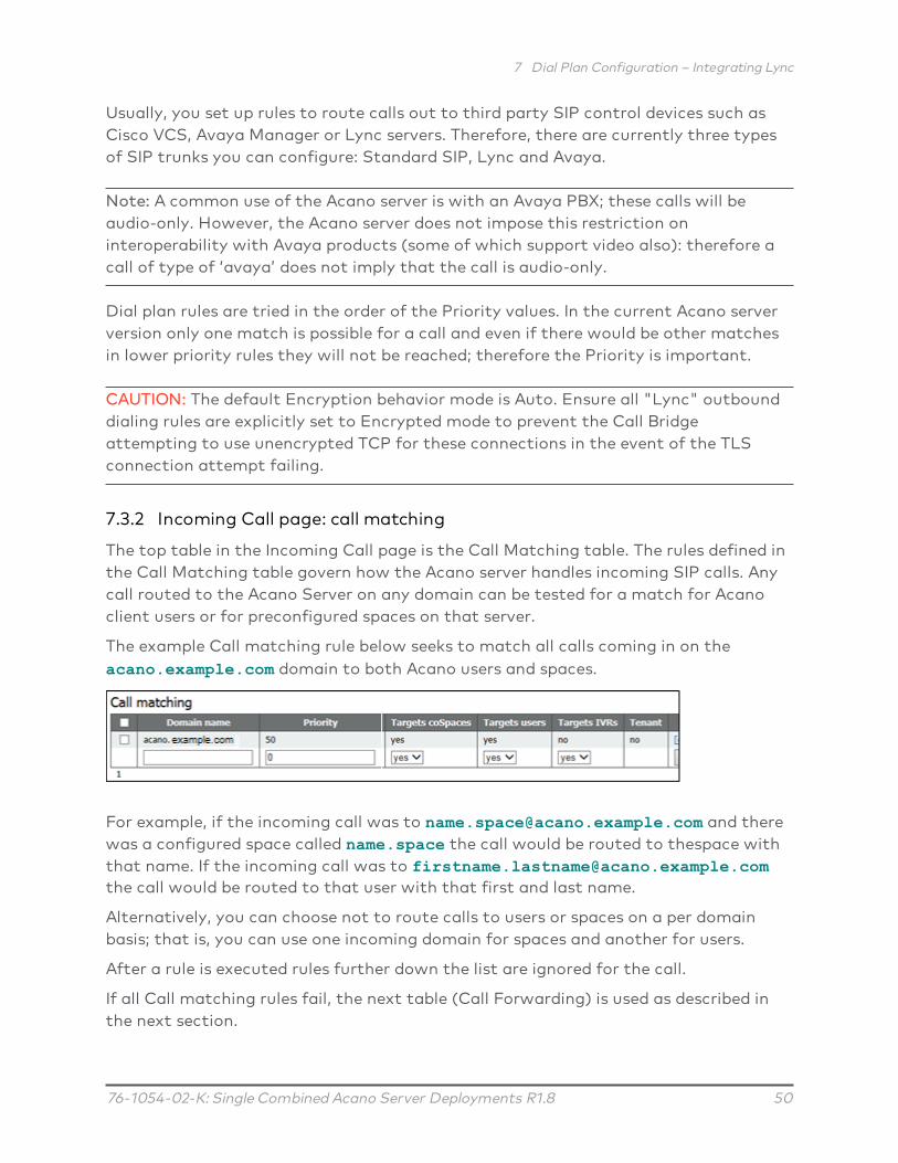
The top table in the Incoming Call page is the Call Matching table. The rules defined inthe Call Matching table govern how the Acano server handles incoming SIP calls. Anycall routed to the Acano Server on any domain can be tested for a match for Acanoclient users or for preconfigured spaces on that server.
The example Call matching rule below seeks to match all calls coming in on theacano.example.com domain to both Acano users and spaces.
For example, if the incoming call was to [email protected] and therewas a configured space called name.space the call would be routed to thespace withthat name. If the incoming call was to [email protected] call would be routed to that user with that first and last name.
Alternatively, you can choose not to route calls to users or spaces on a per domainbasis; that is, you can use one incoming domain for spaces and another for users.
After a rule is executed rules further down the list are ignored for the call.
If all Call matching rules fail, the next table (Call Forwarding) is used as described inthe next section.

7 Dial Plan Configuration – Integrating Lync
76-1054-02-K: Single Combined Acano Server Deployments R1.8 51
Points to note:
n Matching for space and/or users is only done on the part of the URI before the @.
n You cannot configure more than one rule with same destination.
n Do not leave the Domain field blank in a rule, otherwise the Call Bridge will refusethe call.
n No rules in the Call matching table will result in all domains being matched.
7.3.3 Call forwarding
If a call fails to match any of the rules in the Call Matching table in the Incoming Callspage, the call will be handled according to the Call Forwarding table. In this table youcan have rules decide whether to reject the call outright or to forward the call inbridge mode. Rules can overlap, and include wildcards. You order rules using thePriority value; higher numbered rules are tried first.
By defining rules, you decide whether to forward the call or not. It might beappropriate to “catch” certain calls and reject them.
For calls that will be forwarded, you can rewrite the Lync destination domain usingthe Forwarding Domain. A new call is created to the specified domain.
The example Call forwarding rule below forwards calls for the domainlync.example.com and the routing is determined by the call routing rules.
If none of the Domain Matching Patterns matches the domain of an incoming callthat was not matched in the Call Matching section, the call is terminated.
7.4 Adding Calls between Lync Clients and SIP Video Endpoints
This section assumes the configuration described in the two dial plan configurationsections has been completed. It expands the example to allow Lync and SIP videoendpoints to call each other in a call using the Acano server as a gateway to transcodethe video and audio (see the figure below).
Note: The Outbound Calls page was used previously to set up a SIP trunk from theAcano server to the Cisco VCS. In order to configure the Acano server to act as a“point-to-point bridge” between Lync and SIP environments, you need to configure callforwarding as described in this section and also set up a SIP trunk from the AcanoServer to other SIP call control devices you are using such as the Lync FE server (see

7 Dial Plan Configuration – Integrating Lync
76-1054-02-K: Single Combined Acano Server Deployments R1.8 52
the appropriate appendix) and Cisco VCS, CUCM, Avaya CM or Polycom DMA (see theThird Party Deployment Guide).
Figure 11: Example of SIP video endpoints and Lync clients in calls
In this example:
n A Lync user can dial <name>@vc.example.com to set up a call with a SIP videoendpoint who is <name>@vc.example.com.
n A SIP video endpoint can dial <name>@example.com to set up a call with a Lyncendpoint who is <name>@example.com.
Adapt the example as appropriate.
7.4.1 Lync Front End Server configuration
To allow Lync clients to call SIP video endpoints:
1. Add a Lync static route pointing to the Acano server for vc.example.com.
7.4.2 VCS configuration
To route SIP video endpoint calls to Lync clients:
1. Add a search rule on the VCS to route calls with the suffix @example.com to theAcano server.

7 Dial Plan Configuration – Integrating Lync
76-1054-02-K: Single Combined Acano Server Deployments R1.8 53
7.4.3 Acano server configuration
Perform the following steps so that all calls to the Acano server that are not matchedto Acano users or spaces are forwarded.
1. Sign in to the Web Admin Interface and go to Configuration > Incoming Calls.
2. In the Call Forwarding section, add a new rule as follows:
l Domain Matching Pattern = *Wildcards are permitted in any part of a domain matching pattern.
(Unmatched calls with a domain that matches this pattern are forwarded usingthis rule.)
l Priority: To ensure that this rule is always used, its priority should be the highestof any rules configured (any value, including 0, is acceptable if there are no otherforwarding rules configured).
(Rules are checked in order of priority; highest priority first. If two DomainMatching Patterns would match a destination domain the rule with the higherpriority is used.)
l Forward = forward
(If you select Reject calls that matched the Domain Matching Pattern are notforwarded but terminate.)
l Rewrite Doman = noThe call will be forwarded using the domain that was called.
(If you select yes here, you must then complete the Forward Domain. The originaldomain will be replaced with the one you enter in Forward Domain before the callis forwarded.)
3. Click Add new.
SIP video endpoints can now call Lync clients by dialing <name>@example.com, andLync clients can call SIP video endpoints by dialing <endpoint>@vc.example.com.
7.5 Integrating Acano Clients with SIP and Lync Clients
Refer to the sections on LDAP Configuration and Configuring the XMPP server forinstructions about configuring your Acano server to use the Acano clients.
If you are using the same LDAP configuration to create both your Lync accounts andAcano clients, problems may occur if a user tries to call a Lync client when using theAcano server as a gateway because the user may end up calling your Acano XMPP
7 Dial Plan Configuration – Integrating Lync
76-1054-02-K: Single Combined Acano Server Deployments R1.8 54
client. The Acano Configuration > Incoming Calls page has a table of rules (CallMatching section) to prevent this.
For example, assume you have an account [email protected] on the Acano server. Ialso have a [email protected] account on my Lync FE server. If a call arrives atthe Acano server and no Call Matching rules are configured, the Acano server willignore the domain and the call will go to the Acano server’s [email protected]. In other words, dialing fred@xxxx will ignore xxxx and see if there is a user“fred” locally.
This is problematic because a user trying to call the Lync [email protected] using the Acano server as a gateway will end up in a call withthe Acano XMPP client logged in as [email protected]. If the same LDAP structurehas been used to create both the Acano server’s and the Lync’s user accounts, this willbe a common problem.
The server is to configure the Incoming Calls page with the Domain Name field set tosomething distinct from the domain that the Lync FE server uses. In the exampleabove, a sensible choice for the Domain Name field would be example.com. Then, a callto [email protected] will reach the Acano client but a call to [email protected] fred@xxxx will not. Instead, if the Call Forwarding section is set up, the Acanoserver forwards the call onwards.
7.6 Lync Edge Server Integration
7.6.1 Lync Edge Call Flow
To establish a call from the Acano Server to the Lync Edge server (see Figure 12 below):
1. The Acano Call Bridge makes a “register” SIP call to the Lync Front End server.
2. The “register” is acknowledged.
3. The Call Bridge sends a “service” to the Lync Front End server.
4. The Front End server returns the URI of the media relay authentication server(MRAS). (The Lync Edge Server acts as a MRAS.)
5. The Lync client initiates an incoming call.
6. The Call Bridge sends “service” messages to the Lync Front End server to requestMRAS Credentials to use the Lync Edge MRAS Service
7. The Lync Front End server returns the credentials for the Call Bridge to use, as wellas the UDP and TCP ports, and the MRAS URI once again
8. The Call Bridge resolves this MRAS URI using DNS and starts sending STUNmessages directly to the Lync Edge server

7 Dial Plan Configuration – Integrating Lync
76-1054-02-K: Single Combined Acano Server Deployments R1.8 55
9. The call media then flows directly between the Call Bridge and Lync Edge’s TURNserver on UDP port 3478 and returns from the Lync Edge server to the Call Bridgeon a port in the ephemeral range above.
Therefore the following ports need to be opened in the firewall for the media betweenCall Bridge and the Edge server: UDP 3478 outgoing and 32768-65535 incoming.
Figure 12: Call Bridge to Lync Edge Server Call Flow
7 Dial Plan Configuration – Integrating Lync
76-1054-02-K: Single Combined Acano Server Deployments R1.8 56
7.6.2 Configuration for using Lync Edge
To use a Lync Edge server, log in to the Web Admin Interface, go to Configuration >General and configure the Lync Edge Settings. (When a Lync Edge server is configured,it takes the TURN / ICE role for Lync calls, and so at some level is an alternative to theTURN Server Settings above).
You also need to create a Lync user client account to set up the Acano Lync ServerEdge configuration.
Follow these steps to set up the Acano server to use the Lync Edge server:
1. Ensure that you have the appropriate DNS records in place; see Appendix A for alist of DNS records needed for the single combined type deployment.
2. Create a new user in your LDAP directory, just as you would any other user in yourdirectory, for example, firstname=”edge”, second name = “user”.
3. Login into the user manager on your Lync FE Server and create a Lync Client userfrom the user you created in the previous step. Do this in the same way as youwould any other user to enable them to use Lync. Using the example name abovecreate a Lync client user called [email protected]
4. Sign in to the Web Admin Interface of the Acano server, and go to Configuration >General. Configure the Lync Edge Settings by entering the Lync Front End ServerAddress (or a host name that resolves to this). For Username enter the Lync clientuser name created in the previous step.
5. Complete the Number of Registrations field, if necessary.
This field overcomes a feature of the Lync Edge server that limits the number ofsimultaneous calls that it will run for one registered device. By entering a numbergreater than 1, the Call Bridge will make that number of registrations, therebyincreasing the number of simultaneous calls that the Acano server can make outthrough the Lync Edge Server.
Entering a number greater than 1 adds a number to the end of your Lync Edgeusername and registers with the resulting username. For example, if you configuredUsername as [email protected] and set Number of Registrations to 3,you will need to create the following users in your Lync environment so that theycan be used with the Edge server;
[email protected]@[email protected]
We recognize that this requires some administrative overhead; however it is due toa limitation of the Lync Edge server as explained above.

7 Dial Plan Configuration – Integrating Lync
76-1054-02-K: Single Combined Acano Server Deployments R1.8 57
Leave the Number of Registrations blank to only make a single registration [email protected].
Note: There is no need to enter the password for the Lync users because the LyncFront End Server trusts the Call Bridge.
Points to note about configuring the Lync Edge:
n The Acano server supports Lync content (presentations contributed over RDP) fromexternal Lync clients whose media arrives via the Lync Edge server. In addition,space (URIs) now report back as busy or available based on how many participantsare currently in the space so that Lync clients that have Acano spaces in theirfavorites can see the space status.
n If you are using a Lync AVMCU, you need to configure the Lync edge settings inorder to register with the Lync Edge server.
n Acano clients continue to use the Acano TURN Server even if a Lync Edge server isconfigured.
n If you have a Lync Edge server configured, all Lync calls will use that server for ICEcandidate gathering and external media connectivity. If you do not have a LyncEdge server configured, Lync calls handled by the Acano server will use anyconfigured TURN server.
n In a typical Lync Edge deployment, the internal interface of the Lync Edge serverwill not have a default gateway defined; only the external interface has a defaultgateway defined. If the Acano Call Bridge interface is not on the same local subnetas the internal interface of the Lync Edge server, then you must define a static andpersistent network route to the Lync Edge server so it can route packets to theAcano server correctly, using the internal interface. To add a static and persistentnetwork route to the Lync Edge Server, open CMD and issue the command below ,replacing the example data with your own IP information.
Example Command:
route add –p 10.255.200.0 mask 255.255.255.0 10.255.106.1
In this example a network route is added that allows the entire subnet of10.255.200.0 to route through the gateway of 10.255.106.1; 10.255.106.1 is thegateway of the subnet for the internal interface on the Lync Edge server.
Failure to add this route will result in all STUN packets sent by the Acano server tothe Lync Edge server to go unanswered, which can cause call failures in many cases.
7.7 Lync Federation
The Acano server supports federation with Microsoft Lync. This allows calls to bemade from the Acano server to any Lync domain and vice versa.

7 Dial Plan Configuration – Integrating Lync
76-1054-02-K: Single Combined Acano Server Deployments R1.8 58
To allow inbound calls you must:
1. Create the DNS SRV record _sipfederationtls._tcp.domain.com that points to theFQDN of the Acano server. This step is required as Call Bridge will need to have apublic IP, and NAT is not supported in this scenario.
2. Add a DNS A record that resolves the FQDN of the Acano server to a public IPaddress.
3. Upload a certificate and certificate bundle to the Acano server that complies withthe following:
a. The certificate must have the FQDN as the CN, or if using a certificate with aSAN list then ensure that the FQDN is also in the SAN list. Note: if thecertificate contains a SAN list, then Lync will ignore the CN field and only usethe SAN list.
b. The certificate must be signed by a public CA.
Note: you are advised to use the same Certificate Authority (CA) that is trustedby Lync Front End servers. Contact your Lync adviser for details of the CA andfor support on the Acano-Lync integration.
c. The certificate bundle must contain the Root CA’s certificate and allintermediate certificates in the chain in sequence, so that a chain of trust canbe established.
Note: for more information on certificates refer to the Introduction inthe Acano Certificate Guidelines.
d. Open the appropriate Firewall ports as stated in Appendix B for example: TCP5061, UDP 3478, UDP 32768-65535, TCP 32768-65535
For outbound calls from Acano:
1. Create an outbound dial rule, leave the Domain and SIP proxy fields blank, and setTrunk type as Lync. Also set the appropriate Local contact domain and the Localfrom domain fields.
7.8 Calling into scheduled Lync meetings directly and via IVR
Pre-requisite on Lync deployment: This feature requires a working Lync deploymentwith telephone dial-in capabilities already enabled. The Lync deployment requires oneor more on-prem Lync Front End servers to be configured.

7 Dial Plan Configuration – Integrating Lync
76-1054-02-K: Single Combined Acano Server Deployments R1.8 59
From release 1.7, the Acano server supports calling into a scheduled Lync meeting fromWebRTC, SIP or Acano clients, using the Lync call ID to join the call. This featurerequires one or more Lync Front End servers to be configured. You can configure onevia the Web Admin interface under the Lync Edge settings from Configuration >General, and one or more via the API (create them as TURN servers with type"lyncEdge"). Refer to Configuration for using Lync Edge for instructions on how to dothis. If there are multiple FE servers in a Pool, use the Pool FQDN as the ServerAddress.
Note: For Lync meeting resolution, the Acano server uses the Lync meeting ID andDNS lookup of _sipinternaltls._tcp.lync-domain, rather than outbound rules. Set DNSSRV record _sipinternaltls._tcp.lync-domain on your DNS server or if you do not wantto use a DNS SRV record then setup a record on the Acano server with the commanddns app add rr <DNS RR>. For more information on using the dns app commandsee the MMP Command Line Reference; for a list of DNS records needed for the singlecombined type deployment see Appendix A.
Configure the Lync Front End servers, then follow the task sequence in the tablebelow:
Sequence Task On the Web Admin Interface Via the API
1 Configure the Call Bridge IVR(s) toallow entry of Lync conference IDs
If you have set up an IVR via theWeb Admin Interface:
Go to Configuration > Generalin the IVR section, set Joiningscheduled Lync conferences byID to allowed
If you have set upIVRs through the API:
Set resolveLyncConferenceIds totrue for theconfigured IVR
2 Allow direct dialing to Lync con-ference IDs from standard SIP sys-tems Note: you may choose toextend an existing configureddomain to allow Lync conferenceaccess, or to create a new one forthis purpose.
Go to Configuration > Incomingcalls, and for one or more con-figured call matching domains,set Targets Lync to yes
Set resolveToLyncConferences t totrue on the incomingdial plan rule
3 Allow Lync conference ID entry viathe Web Bridge call join interface
If you have set up the WebBridge via the Web AdminInteface:
Go to Configuration > Generalin the Web bridge settingssection ensure that Joiningscheduled Lync conferences byID is set to allowed
If you have set upWeb Bridges throughthe API:
Set resolveLyncConferenceIds totrue on the WebBridge

7 Dial Plan Configuration – Integrating Lync
76-1054-02-K: Single Combined Acano Server Deployments R1.8 60
If a call is being matched against Lync conference IDs, the Call Bridge first checks thatthe call ID does not apply to a space, if it does not then the Call Bridge identifies aLync Front End server that it has been configured with, that has advertised itself ashaving the capability to resolve IDs. The Call Bridge queries the Lync Front End serverto determine whether the call ID in question corresponds to a Lync conference - if itdoes, the look up is deemed to have been successful and the call is joined to the Lynccall. If the call ID is not recognized as corresponding to a Lync conference then nofurther Lync Front End servers will be queried.
Note: You may get unexpected results if you add the settings of multiple Lync FrontEnd servers that are in different Lync deployments. For instance, if multiple Lyncconferences in different Lync deployments use the same call ID, then more than oneLync Front End server may respond positively to the lookup, in which case the "first"successful Lync resolution is used.
The text in the invitations sent for scheduled Lync meetings can be customized toinclude the necessary details to allow users to join via Acano. These details should beplaced in the custom footer section. For example ‘For SIP/H.323 endpoints, join bycalling [email protected] and entering the conference ID above. For WebRTC go tojoin.example.com and enter the conference ID above.’ The URIs in this must matchthose configured above. Please see the Microsoft documentationhttps://technet.microsoft.com/en-us/library/gg398638.aspx for more details.

8 SIP and Lync call traversal of local firewalls
76-1054-02-K: Single Combined Acano Server Deployments R1.8 61
8 SIP and Lync call traversal of local firewalls
Note: SIP and Lync call traversal of local firewalls is a beta feature in release 1.8, itshould not be used in production environments.
From R1.8, the Acano server supports traversal of local firewalls for SIP endpoints andLync calls. The Call Bridge uses the TURN server component within the Acano server totraverse the local firewall and sends the SIP signal via a new SIP Edge component. Athird party SIP firewall traversal device is no longer required.
You need to set up an Outbound dial plan rule, even if you don’t plan on makingoutgoing calls via the SIP edge. This is because any new transaction within the call orsending content to a Lync device uses the outbound rule. Once the SIP Edge has beenconfigured and enabled, incoming calls from SIP devices are automatically traversedacross the firewall.
Note: this feature assumes that the remote SIP device can see the TURN server. It doesnot require the remote SIP device to be ICE aware. It also requires the remote SIPdevice to be able to contact the SIP Edge, the SIP Edge can either have a public IPaddress or sit behind a NAT with appropriate forwarding of traffic.
Figure 13 shows a schematic for SIP call traversal using the TURN server and SIP Edgecomponent in the DMZ network which is accessible to remote SIP devices via thepublic IP address 203.0.113.1. The Call Bridge is deployed in the private network andaccesses the TURN server and SIP Edge via the internal IP address 198.51.100.1. Thetable below Figure 13 lists the ports required to be open for SIP/Lync call traversal.
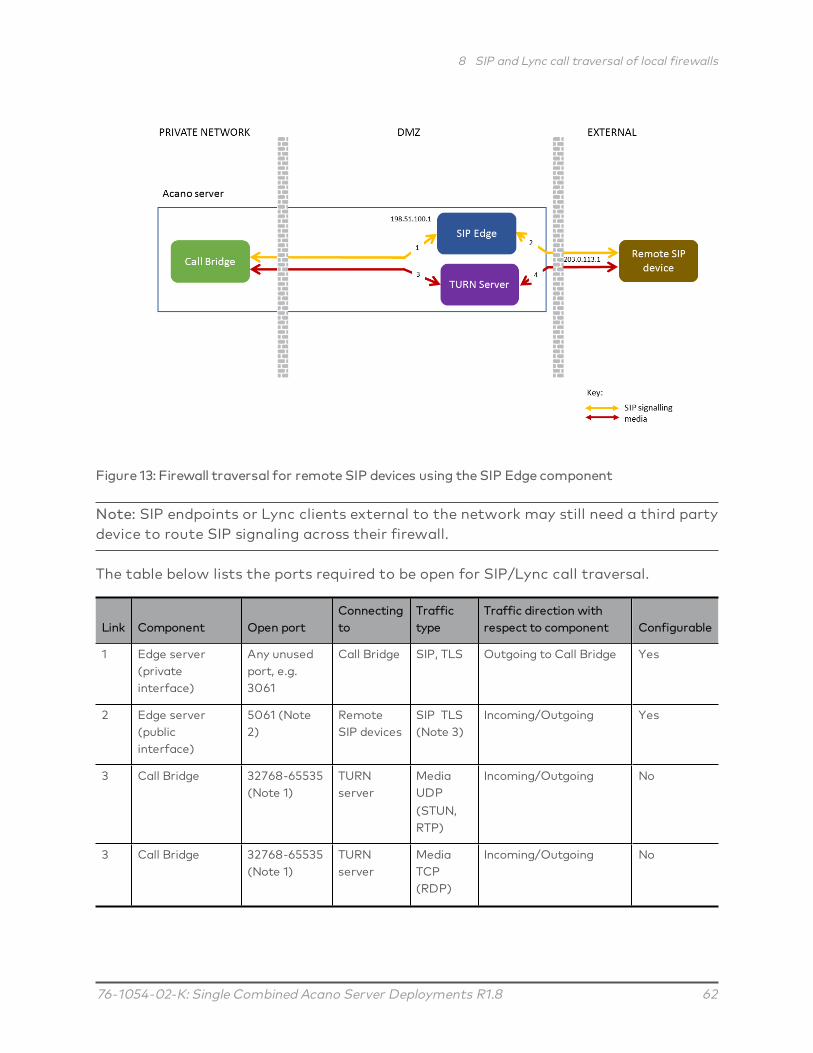
8 SIP and Lync call traversal of local firewalls
76-1054-02-K: Single Combined Acano Server Deployments R1.8 62
Figure 13: Firewall traversal for remote SIP devices using the SIP Edge component
Note: SIP endpoints or Lync clients external to the network may still need a third partydevice to route SIP signaling across their firewall.
The table below lists the ports required to be open for SIP/Lync call traversal.
Link Component Open portConnectingto
Traffictype
Traffic direction withrespect to component Configurable
1 Edge server(privateinterface)
Any unusedport, e.g.3061
Call Bridge SIP, TLS Outgoing to Call Bridge Yes
2 Edge server(publicinterface)
5061 (Note2)
RemoteSIP devices
SIP TLS(Note 3)
Incoming/Outgoing Yes
3 Call Bridge 32768-65535(Note 1)
TURNserver
MediaUDP(STUN,RTP)
Incoming/Outgoing No
3 Call Bridge 32768-65535(Note 1)
TURNserver
MediaTCP(RDP)
Incoming/Outgoing No

8 SIP and Lync call traversal of local firewalls
76-1054-02-K: Single Combined Acano Server Deployments R1.8 63
Link Component Open portConnectingto
Traffictype
Traffic direction withrespect to component Configurable
4 TURN server 32768-65535(Note 1)
RemoteSIP devices
MediaUDP(STUN,RTP)
Incoming No
4 TURN server 32768-65535(Note 1)
RemoteSIP devices
MediaTCP(RDP)
Incoming No
3,4 TURN server 3478 RemoteSIP devices
UDP Incoming Yes
3,4 TURN server 443 RemoteSIP devices
TCP Incoming Yes
Note 1: Although the range between the TURN server and the external Acano clients is shown as 32768-65535, currently only 50000-51000 is used. A wider range is likely to be required in future releases.Note 2: Port 5061 is normally used for SIP TLSNote 3: From R1.8 only SIP TLS is supported, there is no support for UDP or TCP on port 5060
8.1 Configuring SIP/Lync call traversal
1. Set up a SIP Edge on the Acano server.
a. Configure the internal interface and port for communication to the Call Bridge.If the Call Bridge is using port 5061, then use a different port. In a singlecombined deployment, the SipEdge needs to listen to the local interface.sipedge private <local interface>:port
for example: sipedge private lo:3061
b. Configure the external interface and port on the SIP Edgesipedge public b:5061
for example: sipedge public b:5061
Note: The SIP Edge always uses TLS for communication. Typically SIP TLS usesport 5061.
c. If the SIP Edge is behind a NAT, then configure the public address of the NAT.sipedge public-ip <address>
for example: sipedge public-ip 203.0.113.0

8 SIP and Lync call traversal of local firewalls
76-1054-02-K: Single Combined Acano Server Deployments R1.8 64
Note: DNS records used for external connections must match the publicaddress
d. Set up a certificate, key file and trust bundle on the SIP Edge. These files areused to communicate with the internal Call Bridge and the external SIP server.If you have previously assigned a public CA signed certificate to the Call Bridge,then you can use the same certificate on the SIP Edge. If the SIP Edge hasdirect federation with a Lync Edge server, then the certificate file must besigned by a public CA trusted by the Lync deployment (as was previouslyrequired for the Call Bridge).
Combine the Call Bridge certificate and the chain of CA certs into one file anduse this as the SIP Edge certificate <crt-file>. To enable the SIP Edge to trustthe Call Bridge for the TLS trunk, use the Call Bridge certificate as the <trust-bundle>.sipedge certs <key-file> <crt-file> <trust-bundle>
for example:
sipedge certs sipedge.key sipedge.crt callbridge.crt
Note: SIP Edge certificates need to be signed by a public CA and trusted by thethird party SIP server. Apply the certificate to the SIP Edge and the Call Bridge.For more information on certificates refer to the Certificate deployment guide.
e. Enable the SIP Edgesipedge enable
2. Set up a trunk from the Call Bridge to the SIP Edge. Note that you need toconfigure trust between the Call Bridge and the SIP Edge before creating the trunk.
Note: Currently, only one trunk can be made to any SIP Edge, and only one trunkcan be made from the same Call Bridge.
a. Set up certificates for the connection to the SIP Edge. This uses the certificatefrom the SIP Edge as used above.callbridge trust edge <certificate file>
for example: callbridge trust edge sipedge.crt
b. Create the trunk using the IP address and port of the private interface.callbridge add edge <ip address>:<port>
for example: callbridge add edge 198.51.100.0:3061
3. Set DNS records to point to SIP Edge(s) for SIP and/or Lync. DNS can point tomultiple SIP Edges for resilience. Use the _sips._tcp<domain> SRV record for the

8 SIP and Lync call traversal of local firewalls
76-1054-02-K: Single Combined Acano Server Deployments R1.8 65
external TLS connection.
4. Configure the TURN server as explained in Chapter 11. Note that TURN TLS isrequired for Lync content data packets as they use TCP and not UDP.
5. Create the outbound dial plan rule. Use the API to PUT to the relevant outbounddial plan rule ‘/api/v1/outboundDialPlanRules/ <outbound dial plan rule id>’, with‘callRouting=traversal’
Points to note:
n You cannot use the Web Admin interface to select the call routing.
n Outgoing calls use the certificates that you setup for incoming calls, see step 1dabove.
n The SIP Edge only supports TLS. All dial plan rules targeting the SIP Edge mustbe set to ‘sipControlEncryption=encrypted’.
n The Call Bridge determines the next hop of the signaling by doing a DNS lookup.It then sends this information to the SIP Edge using the outbound rules.
The table below outlines the call flow to establish an outgoing call from the AcanoServer to a remote SIP device via the SIP Edge server.
See signals in Figure13 and 8 Call Flow
1 Call Bridge uses an outbound dial plan rule to route SIP signaling via the SIP Edgeserver
1 Call Bridge sends a DNS request to resolve the next hop to send the request to
1 Call Bridge sends the requests to the SIP Edge with both local address and theTURN address for receiving media
2 The SIP Edge server makes the outgoing call to the remote SIP device
The remote SIP device answers the call
3,4 Media flows between the TURN server and the remote SIP device

9 Web Admin Interface Settings for XMPP
76-1054-02-K: Single Combined Acano Server Deployments R1.8 66
9 Web Admin Interface Settings for XMPPThis section explains how to configure the settings through which the Call Bridgecommunicates with XMPP server.
Note: If you are not using the Acano clients including the WebRTC Client, skip thissection.
9.1 Network Topology
The following diagram shows a possible network topology and is used for the examplesin this section.
Figure 14: Example network topology showing XMPP server

9 Web Admin Interface Settings for XMPP
76-1054-02-K: Single Combined Acano Server Deployments R1.8 67
9.2 XMPP Settings
1. Ensure that you have installed a security certificate for the XMPP server.
2. Ensure that you have configured the XMPP server using the MMP.
3. If you are using a virtual host, ensure that you have uploaded the license key file.
4. Log in to the Web Admin Interface and configure the XMPP server settings asfollows:
a. Go to Configuration > General
b. Complete the fields in the XMPP Server Settings section.
l Unique Call Bridge name (this is the component name set up previously, nodomain part is required, as shown):
cb_london
l Domain (this is the XMPP server domain set up previously:
example.com
l Server Address is the IP address or hostname of the XMPP server, with anoptional <port> (default is 5223):
localhost:5223
Note: If you are using DNS to locate the XMPP server it is not necessary toconfigure the server address.
l Shared secret: as generated during the XMPP server configuration (see step 9in Section 4.5).
c. Save your configuration by selecting Submit at the bottom of this page.
5. Go to Status > General and verify the server connection.You should see details similar to the following in the XMPP Connection field:
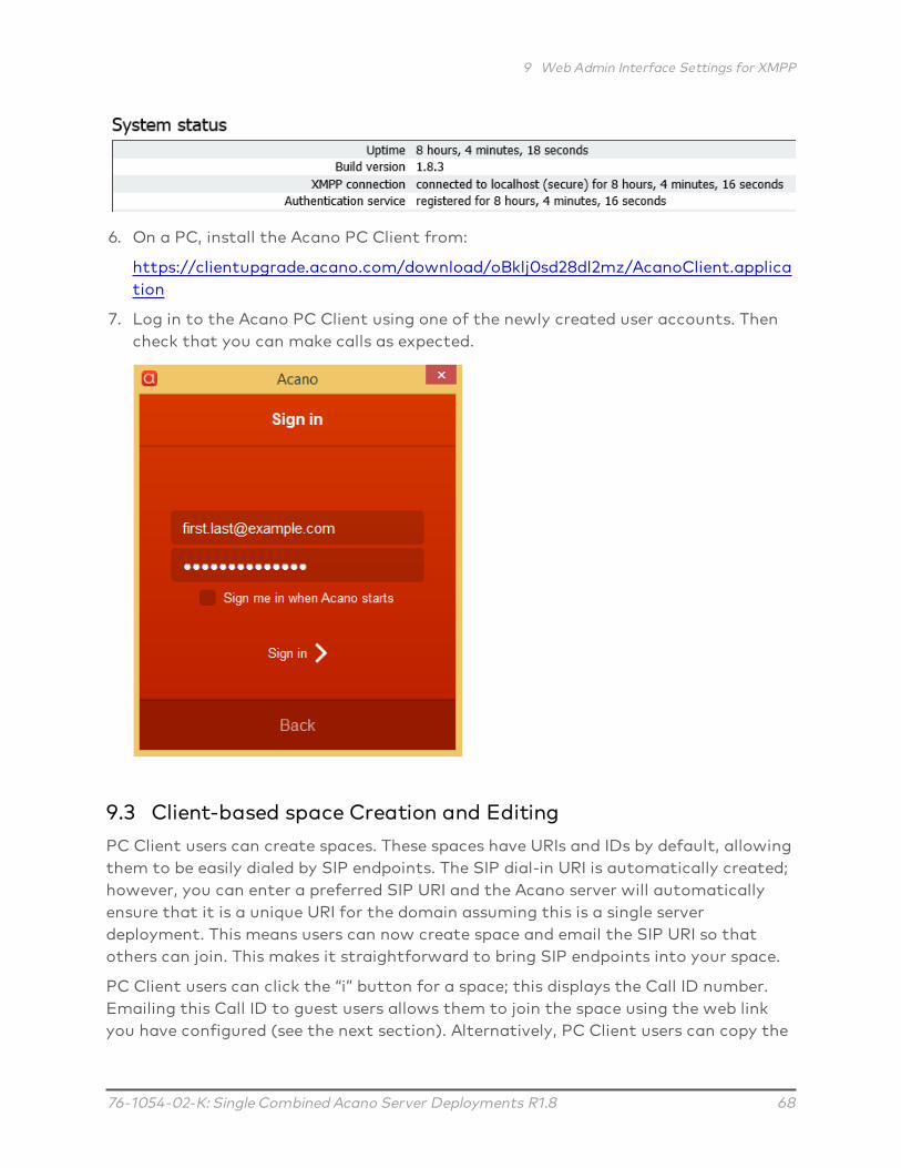
9 Web Admin Interface Settings for XMPP
76-1054-02-K: Single Combined Acano Server Deployments R1.8 68
6. On a PC, install the Acano PC Client from:
https://clientupgrade.acano.com/download/oBklj0sd28dl2mz/AcanoClient.application
7. Log in to the Acano PC Client using one of the newly created user accounts. Thencheck that you can make calls as expected.
9.3 Client-based space Creation and Editing
PC Client users can create spaces. These spaces have URIs and IDs by default, allowingthem to be easily dialed by SIP endpoints. The SIP dial-in URI is automatically created;however, you can enter a preferred SIP URI and the Acano server will automaticallyensure that it is a unique URI for the domain assuming this is a single serverdeployment. This means users can now create space and email the SIP URI so thatothers can join. This makes it straightforward to bring SIP endpoints into your space.
PC Client users can click the “i” button for a space; this displays the Call ID number.Emailing this Call ID to guest users allows them to join the space using the web linkyou have configured (see the next section). Alternatively, PC Client users can copy the

9 Web Admin Interface Settings for XMPP
76-1054-02-K: Single Combined Acano Server Deployments R1.8 69
full web link in space information by right-clicking and email it to guests. This linkbypasses the guest “call ID” page above, going directly to the guest identificationpage.
Note: spaces can also be created using the Acano server API (see the API Referenceguide), or by using the Web Admin Interface Configuration > spaces page.

10 Web Admin Interface Settings for the Web Bridge
76-1054-02-K: Single Combined Acano Server Deployments R1.8 70
10 Web Admin Interface Settings for the WebBridgeThis section explains how to configure the settings through which the Call Bridgecommunicates with the Web Bridge server. This allows you to use WebRTC video callsand meetings.
If you are testing the WebRTC client, follow the instructions in Section 10.2 in theorder provided at any time after the initial Acano server configuration has beencompleted. If you are not using this Acano client, skip this section.
10.1 Network Topology
Figure 15: Example network topology showing Web Bridge

10 Web Admin Interface Settings for the Web Bridge
76-1054-02-K: Single Combined Acano Server Deployments R1.8 71
Figure 16: WebRTC Client port usage
Note: If you have setup TURN TLS (see Section 4.7) to use a different port to 443, forexample 447, then that port will be used.
If the media ports (32768-65535) are not open then port 3478 will be used and if that isnot open, then the port setup for TURN TLS will be used, if setup.
* Although the port range between the TURN server and the External clients is shownas 32768-65535, currently only 50000-51000 is used. The required range is likely to belarger in future releases.
10.1.1 Web Bridge Call Flow
1. PC Web Browser opens HTTPS connection to Web Bridge
2. User is prompted to Join Call (see step 3) or Sign In (see step 4)
3. If Join Call is selected, user is prompted to enter the Call ID and Passcode (ifrequired)
a. Web Bridge queries Call Bridge to validate Call ID and Passcode
b. If successful, the User is prompted to enter a Name to be displayed in the call
c. Upon completing these steps and clicking Join Call, the Web RTC client sendsan http message to the Web Bridge on port 443, which requests temporarycredentials from the Call Bridge over port 443

10 Web Admin Interface Settings for the Web Bridge
76-1054-02-K: Single Combined Acano Server Deployments R1.8 72
d. Web Bridge then connects to the XMPP Server on port 5222, using the abovetemporary credentials, and the Call Bridge validates the credentials
e. Call Bridge requests allocations from the TURN Server to use for this call onUDP 3478
f. WebRTC client requests allocations from the TURN Server to use for this callon UDP 3478 (or TCP 443)
g. If the UDP STUN packets sent by the WebRTC client to the TURN server aresuccessful, the WebRTC Client will send media from the TURN server, with aMedia Port range of 32768-65535
h. If the UDP STUN messages are un-successful, the WebRTC Client will fall backand send messages to the TURN Server on TCP Port 443
i. If the TCP connection is successful, Media will also be sent to the TURN Serveron TCP Port 443
j. The TURN Server will then relay this WebRTC Media to Call Bridge, convertingto UDP if received as TCP from WebRTC Client
4. If Sign In is selected, user is prompted to enter Username and Password
a. Web Bridge will do DNS Lookup for the SRV record of _xmpp-client._tcp forthe domain entered in the Username field
b. Web Bridge connects to the XMPP Server returned in the DNS lookup andsends the Credentials as supplied for verification
c. If Login is successful, the User is logged into the WebRTC client and is shown aClient view similar to the PC XMPP Client
d. Upon attempting a New Call or joining a Meeting, the client will connect asfollows
e. Web Bridge signals Call Bridge for the call request over XMPP
f. Call Bridge opens connections to the TURN Server to request allocations forPorts to use for this call on UDP 3478
g. Once TURN allocations have succeeded, Call Bridge answers the call and sendsthe Address and Ports to use back to Web Bridge to be relayed to the WebRTCClient
h. WebRTC client requests allocations from the TURN Server to use for this callon UDP 3478 (or TCP 443)
i. If the UDP messages are successful, the WebRTC Client will send messages tothe Media Port range of 32768-65535, using the specific ports relayed to itfrom Call Bridge

10 Web Admin Interface Settings for the Web Bridge
76-1054-02-K: Single Combined Acano Server Deployments R1.8 73
j. If the UDP messages are un-successful, the WebRTC Client will fall back andsend messages to the TURN Server on TCP Port 443
k. If the TCP connection is successful, Media will also be sent to the TURN Serveron TCP Port 443
l. The TURN Server will then relay this WebRTC Media to Call Bridge, convertingto UDP if received as TCP from WebRTC Client
10.2 Web Bridge Settings
Follow the steps in order.
1. Ensure that you have installed the Web Bridge certificate.
Note: If you are intending to use branding you need to apply the license key to theserver.
2. Ensure that you have configured the Web Bridge.
3. Sign in to the Web Admin Interface and configure the Acano server as follows:
a. Go to Configuration > General.
b. Set the following where:
l Guest Account Client URI = The URI to reach the guest account, you need toinclude https:// for example https://join.example.com
l Guest Account JID Domain = guest account JID, e.g. example.com
l Guest access via ID and passcode - if you change this setting from secure tolegacy then you will reduce the security of the guest sign in. Instead ofrequiring both the ID and the passcode to be entered before selecting theJoin button, the legacy mode allows the guest to enter the call ID followedby the passcode once the call ID is matched to a space.

10 Web Admin Interface Settings for the Web Bridge
76-1054-02-K: Single Combined Acano Server Deployments R1.8 74
l Guest access via hyperlinks – a guest can join a space by clicking a hyperlinkincluded in a meeting invite. If this is set to allowed, a link that includes asecret and an id will immediately resolve to a conference that might bepasscode protected. The complexity of the secret prevents brute forceattacks. If set to not allowed, a guest user may need to enter someadditional details, such as the space passcode, before the conference lookupis performed.
l User sign in – if set to allowed, registered users and guests can join spacesusing the WebRTC client. If set to not allowed, registered users will not beable to sign in using the WebRTC client.
l Joining scheduled Lync conferences by ID - if set to allowed, Web RTC clientscan join scheduled Lync conferences by entering the Lync meeting id fromthe WebRTC landing page.
4. Open a web browser and go to the URI for the Guest account client, forexample:https://join.example.com to test the configuration.
Guest users selecting theweb link will see a landing page in which they can entertheir name to join the call.
In addition, Acano users who do not have access to a native Acano client but havean account can select the Back button at the bottom of the login box to sign in asthey would on a native client. After signing in they see their spaces, participate inmeetings and can invite participants t o meetings - all from the WebRTC Client.

10 Web Admin Interface Settings for the Web Bridge
76-1054-02-K: Single Combined Acano Server Deployments R1.8 75
Note: Acano clients (PC Client ClickOnce, Mac Client DMG download , iOS Clientdownload) can be downloaded at: www.acano.com/help.

11 Web Admin Interface Settings for the TURN Server
76-1054-02-K: Single Combined Acano Server Deployments R1.8 76
11 Web Admin Interface Settings for the TURNServerThis section explains how to configure the settings through which the Call Bridgecommunicates with the TURN server. The TURN server allows you to use the built-infirewall traversal technology when traversing a firewall or NAT.
Follow the instructions below in the order provided at any time after the initial Acanoserver configuration has been completed.
11.1 Network Topology
Figure 17: Example network topology showing TURN Server

11 Web Admin Interface Settings for the TURN Server
76-1054-02-K: Single Combined Acano Server Deployments R1.8 77
11.2 TURN Server Settings
Follow the steps in order.
1. Ensure that you have configured the TURN server.
2. Log in to the Web Admin Interface and configure the Acano server as follows:
a. Go to Configuration > General.
b. Set the following:
l TURN Server Address (Server) = internal server IP address that the Call Bridgewill use to access the TURN server to avoid firewall traversal for internal callcontrol
l TURN Server Address (Clients) = public IP address assigned to the TURNserver that external clients will use to access the TURN server. This will be theIP address entered in Section 4.7 when you configured the TURN server.
Note:For example, if the interface of the TURN Server is on IP address XX.XX.XX.XXand NAT'ed to an external IP address YY.YY.YY.YY then enter XX.XX.XX.XX asthe TURN Server Address (Server) and YY.YY.YY.YY as TURN Server Address(Client). If the interface is on the external IP then no need to enter a clientaddress.
You can enter a DNS name instead of an IP address in both fields, if the DNSname resolves to the appropriate IP address.
If you are using a public IP address, leave TURN Server Address (Clients)address blank and set TURN Server Address (Server) to the public IP addressor DNS name used
l Username and Password = your information

12 Additional Security Considerations & QoS
76-1054-02-K: Single Combined Acano Server Deployments R1.8 78
12 Additional Security Considerations & QoSThis chapter discusses other security features available on the Acano server that are inaddition to authentication provided through X.509 certificates and public keys.
Note: The commands listed in this chapter are also listed in the MMP CommandReference Guide.
12.1 Common Access Card (CAC) integration
The Common Access Card (CAC) is used as an authentication token to accesscomputer facilities. The CAC contains a private key which cannot be extracted but canbe used by on-card cryptographic hardware to prove the identity of the card holder.
The Acano server supports administrative logins to the SSH and Web Admin Interfaceusing CAC. Use the MMP commands in the table below to configure CAC for yourdeployment.
MMP commands Description
cac enable|disable [strict] Enables/disables CAC mode with optional strict mode removing allpassword-based logins
cac issuer <ca cert-bundle> Identifies trusted certificate bundle to verify CAC certificates
cac ocsp certs <key-file><crt-file>
Identifies certificate and private key for TLS communications withOCSP server, if used
cac ocsp responder <URL> Identifies URL of OCSP server
cac ocsp enable|disable Enables/disables CAC OCSP verification
12.2 Online Certificate Status Protocol (OCSP)
OCSP is a mechanism for checking the validity and revocation status of certificates.The MMP can use OCSP to work out whether the CAC used for a login is valid and, inparticular, has not been revoked.
12.3 FIPS
You can enable a FIPS 140-2 level 1 certified software cryptographic module, thencryptographic operations are carried out using this module and cryptographicoperations are restricted to the FIPS approved cryptographic algorithms.

12 Additional Security Considerations & QoS
76-1054-02-K: Single Combined Acano Server Deployments R1.8 79
MMP commands Description
fipsenable|disable
Enables/disables the FIPS-140-2 mode cryptography for all cryptographic operations fornetwork traffic. After enabling or disabling FIPS mode, a reboot is required
fips Displays whether FIPS mode is enabled
fips test Runs the built-in FIPS test
12.4 TLS Certificate Verification
You can enable Mutual Authentication for SIP and LDAP in order to validate that theremote certificate is trusted. When enabled, the Call Bridge will always ask for theremote certificate (irrespective of which side initiated the connection) and comparethe presented certificate to a trust store that has been uploaded and defined on theserver.
MMP commands Description
tls <sip|ldap> trust <crtbundle>
Defines Certificate Authorities to be trusted
tls <sip|ldap> verifyenable|disable|ocsp
Enables/disables certificate verification or whether OCSP is to beused for verification
tls <sip|ldap> displays current configuration
12.5 User Controls
MMP admin users can:
n Reset another admin user’s password
n Set the maximum number of characters that can be repeated in a user’s password –and there are a number of other user password rule additions
n Limit MMP access by IP address
n Disable MMP accounts after configurable idle period
12.6 Firewall Rules
The MMP supports the creation of simple firewall rules for both the media and admininterfaces. Note that this is not intended to be a substitute for a full standalonefirewall solution and therefore is not detailed here.
Firewall rules must be specified separately for each interface. After setting up afirewall rule on an interface, remember to enable the firewall on that interface. Seethe MMP Command Reference for full details and examples.

12 Additional Security Considerations & QoS
76-1054-02-K: Single Combined Acano Server Deployments R1.8 80
CAUTION: We recommend using the serial console to configure the firewall, becauseusing SSH means that an error in the rules would make the SSH port inaccessible. Ifyou must use SSH then ensure that an allow ssh rule is created for the ADMINinterface before enabling the firewall.
12.7 DSCP
You can enable DSCP tagging for the different traffic types on the Acano server (seethe MMP Command Reference).
1. Sign in to the MMP and set the DSCP values as required.
2. Go to Configuration > Call Settings and set the DSCP Mode as follows:
l In a non-AS SIP environment, select Use Normal Values
l In an AS SIP environment, select Use Assured Values
Note: DSCP tagging is for all packets being sent from the Acano server only. For PCClient DSCP tagging, Group Policy must be used to define desired DSCP valuesbecause Windows controls this, and normal user accounts have no permissions to setDSCP.
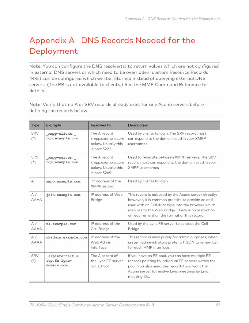
Appendix A DNS Records Needed for the Deployment
76-1054-02-K: Single Combined Acano Server Deployments R1.8 81
Appendix A DNS Records Needed for theDeployment
Note: You can configure the DNS resolver(s) to return values which are not configuredin external DNS servers or which need to be overridden; custom Resource Records(RRs) can be configured which will be returned instead of querying external DNSservers. (The RR is not available to clients.) See the MMP Command Reference fordetails.
Note: Verify that no A or SRV records already exist for any Acano servers beforedefining the records below.
Type Example Resolves to Description
SRV(*)
_xmpp-client._tcp.example.com
The A recordxmpp.example.combelow. Usually thisis port 5222.
Used by clients to login. The SRV record mustcorrespond to the domain used in your XMPPusernames
SRV(*)
_xmpp-server._tcp.example.com
The A recordxmpp.example.combelow. Usually thisis port 5269
Used to federate between XMPP servers. The SRVrecord must correspond to the domain used in yourXMPP usernames
A xmpp.example.com IP address of theXMPP server.
Used by clients to login
A /AAAA
join.example.com IP address of WebBridge
This record is not used by the Acano server directly;however, it is common practice to provide an enduser with an FQDN to type into the browser whichresolves to the Web Bridge. There is no restrictionor requirement on the format of this record.
A /AAAA
uk.example.com IP address of theCall Bridge
Used by the Lync FE server to contact the CallBridge
A /AAAA
ukadmin.example.com IP address of theWeb AdminInterface
This record is used purely for admin purposes; whensystem administrators prefer a FQDN to rememberfor each MMP interface.
SRV(*)
_sipinternaltls._tcp.fe.lync-domain.com
The A record ofthe Lync FE serveror FE Pool
If you have an FE pool, you can have multiple FErecords pointing to individual FE servers within thepool. You also need this record if you want theAcano server to resolve Lync meetings by Lyncmeeting IDs.

Appendix A DNS Records Needed for the Deployment
76-1054-02-K: Single Combined Acano Server Deployments R1.8 82
Type Example Resolves to Description
A /AAAA
fe.lync-domain.com IP address of theLync FE server
You will need one record for each individual FEserver
(*) SRV records do not resolve directly to IP addresses. You need to create associated Aor AAAA name records in order to satisfy the SRV requirements.

Appendix B Ports Required for the Deployment
76-1054-02-K: Single Combined Acano Server Deployments R1.8 83
Appendix B Ports Required for the DeploymentThe following diagram labels the links on which ports need to be open and showswhich firewall is concerned in a single combined server deployment.
Figure 18: Ports that must be open in a single combined server deployment
The following ports are required by the Call Bridge.
Function Destination Port Type Direction Used on Link(s) Configurable?
HTTP 80 TCP Incoming M MMP
HTTPS 443 TCP Incoming M, N MMP (for M)
SIP UDP 5060 UDP Both I
SIP TCP 5060 TCP Both I

Appendix B Ports Required for the Deployment
76-1054-02-K: Single Combined Acano Server Deployments R1.8 84
Function Destination Port Type Direction Used on Link(s) Configurable?
SIP TLS 5061 TCP Both I, K
SIP BFCP 32768-65535 UDP Incoming II
SIP BFCP 1024-65535 (Note 1) UDP Outgoing II
TURN 3478 UDP Outgoing O
TURN 443 TCP Outgoing O
STUN/RTP 32768-65535 UDP Incoming II, JJ, KK,
STUN/RTP 32768-65535 UDP Incoming O
STUN/RTP 1024-65535 (Note 1) UDP Outgoing II, JJ, KK
RDP 32768-65535 TCP Incoming KK
RDP 1024-65535 (Note 2) TCP Outgoing KK
LDAP/LDAPS 636/389 (Note 3) TCP Outgoing H Web Admin Interface
DNS 53 UDP Outgoing G
CDR Set in Web Admin Interface TCP Outgoing N Web Admin Interface
Note 1: Exact range depends on far end
Note 2: Exact range depends on configuration on Lync server
Note 3: Ports 636 (secure) and 389 (non-secure) are commonly used for this function but the port isconfigurable. (The same applies to 3268 and 3269 (non-secure and secure) global catalog LDAP requests.)
The following ports are used by MMP
Function Destination Port Type Direction Used in Link(s) Configurable?
SSH 22 TCP Incoming M
Syslog 514 TCP Outgoing F MMP
NTP 123 UDP Outgoing L
SNMP 161 UDP Incoming
SNMP 162 UDP Outgoing
The following ports are used by the Web Bridge
Function Destination Port Type Direction Used in Link(s) Configurable?
HTTP 80 TCP Incoming B MMP
HTTPS 443 TCP Incoming B MMP

Appendix B Ports Required for the Deployment
76-1054-02-K: Single Combined Acano Server Deployments R1.8 85
The following ports are used by the XMPP Server
Function Destination Port Type Direction Used in Link(s) Configurable?
XMPP Client 5222 TCP Incoming A, J
The following ports are used by the TURN Server
Function Destination Port Type Direction Used in Link(s) Configurable?
STUN 3478 UDP Incoming A, B
STUN RTP 32768-65535 (*) UDP Incoming A, B
* Although the range between the TURN server and the external Acano clients is shown as 32768-65535,currently only 50000-51000 is used. A wider range is likely to be required in future releases.

Appendix C Example of Configuring a Static Route from a Lync Front End Server
76-1054-02-K: Single Combined Acano Server Deployments R1.8 86
Appendix C Example of Configuring a StaticRoute from a Lync Front End Server
Note: Important - This appendix provides an example to be used as a guideline and isnot meant to be an explicit set of instructions for you to follow. Acano stronglyadvises you to seek the advice of your local Lync server administrator on the best wayto implement the equivalent on your server’s configuration.
Before you make configure a static route from the Lync Front End server, ensure thatyou have installed certificates on the Acano serve which will be trusted by the Lync FEserver – as described in the Certificate Guidelines.
C.1 Lync Configuration Changes
1. Optionally, enable HD720p on Lync as follows (if you want HD calls from Lyncbecause the default is VGA):
a. Open the Lync Server Management Shell,
b. Enable support for HD720P Lync calls with:
Set-CsMediaConfiguration -MaxVideoRateAllowed Hd720p15M
2. Add the trusted application and static routes to the Acano server with these fivecommands:
New-CsTrustedApplicationPool -Identity fqdn.acanoserver.com -ComputerFqdn fqdn.acanoserver.com -Registrar fqdn.lyncserver.com -site 1 -RequiresReplication $false -ThrottleAsServer $true -TreatAsAuthenticated $true
Replacing
l fqdn.acanoserver.com with the FQDN of the Acano server
l fqdn.lyncserver.com with your Lync FE Server or Pool FQDN
New-CsTrustedApplication -ApplicationId acano-application -TrustedApplicationPoolFqdn fqdn.acanoserver.com -Port 5061
Replacing
l acano-application with name of your choice
l fqdn.acanoserver.com with the FQDN of the Acano server

Appendix C Example of Configuring a Static Route from a Lync Front End Server
76-1054-02-K: Single Combined Acano Server Deployments R1.8 87
$x=New-CsStaticRoute -TLSRoute -Destination "fqdn.acanoserver.com"-MatchUri "something.com" -Port 5061 -UseDefaultCertificate $true
Replacing
l fqdn.acanoserver.com with your FQDN of the Acano server
l something.com with the URI match of your choosing, possiblyacano.yourcomany.com if that is the domain used for all Acano calls
Set-CsStaticRoutingConfiguration -Identity global -Route @{Add=$x}
Enable-CsTopology
This command enables the new topology. Users may have to logout and login againto update to the new HD720p setting, all other settings are automatic and shouldwork within a few minutes.
C.2 Acano Server Configuration
1. In the Web Admin Interface go to Configuration > Outbound Calls
2. In the blank row, for Domain, enter the Lync domain that will be matched for callsthat need to be sent to Lync
3. For SIP Proxy to Use, do one of the following:
a. Leave this field blank and the server will perform a DNS SRV lookup for thecalled domain using _sipinternaltls._tcp.<yourlyncdomain>.com
b. Enter the Front End Pool (or Lync sip domain) and the server will first perform aDNS SRV lookup for that defined domain using _sipinternaltls._tcp.<yourlyncdomain>.com and then perform a DNS A record lookup for theHost entered if the SRV lookup fails to resolve
c. Enter the IP address of your Lync Front End server
4. For Local Contact Domain, enter the FQDN of your Acano servern. (The only casein which this field should be set is when setting up a trunk to Lync; otherwise itshould be left blank.)
5. For Local From Domain, enter the domain that you want the call to be seen ascoming from (the Caller ID) e.g. acano.yourcompany.com
Note: If you leave Local From Domain blank, the domain used for the Caller IDdefaults to that entered as the Local Contact Domain.

Appendix C Example of Configuring a Static Route from a Lync Front End Server
76-1054-02-K: Single Combined Acano Server Deployments R1.8 88
6. For Trunk Type, select Lync.
7. Select Add New.
After completion you should be able to call from the Lync environment to the Acanoserver and from the Acano server to Lync.
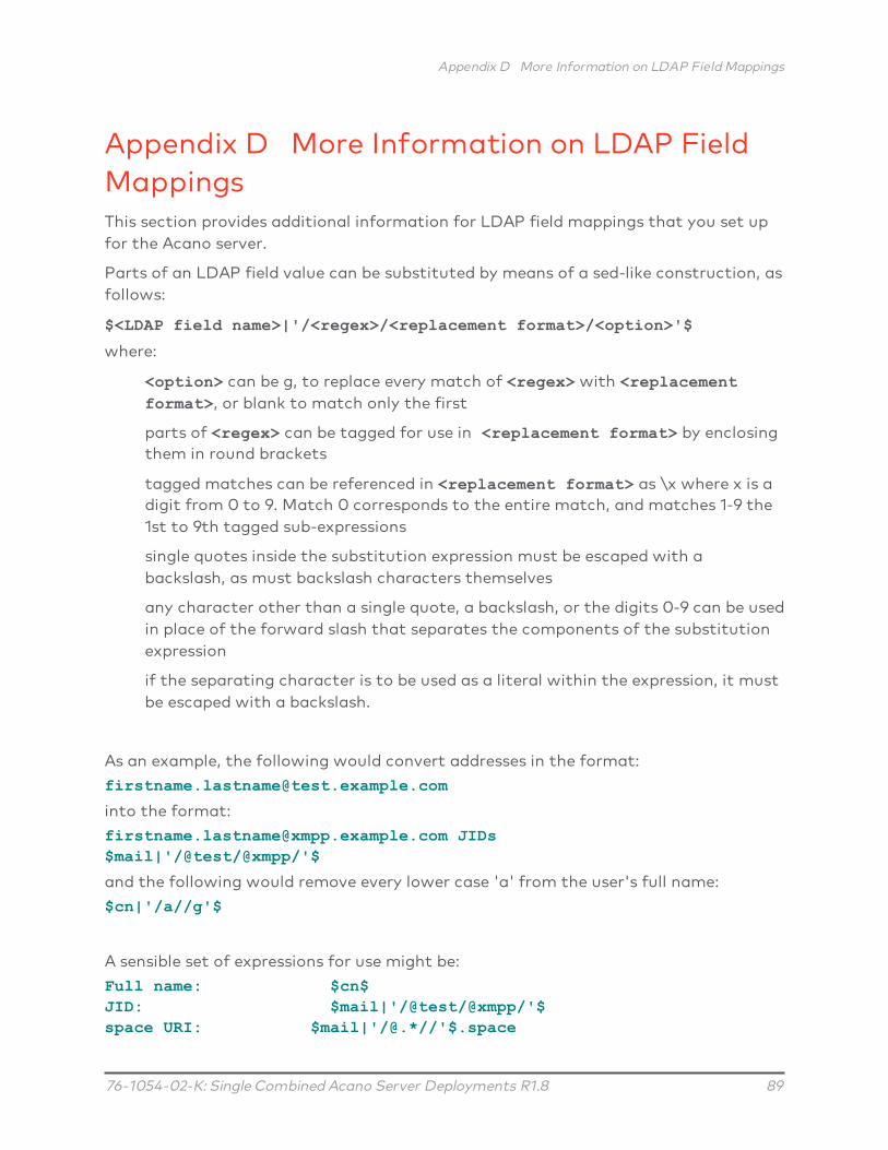
Appendix D More Information on LDAP Field Mappings
76-1054-02-K: Single Combined Acano Server Deployments R1.8 89
Appendix D More Information on LDAP FieldMappingsThis section provides additional information for LDAP field mappings that you set upfor the Acano server.
Parts of an LDAP field value can be substituted by means of a sed-like construction, asfollows:
$<LDAP field name>|'/<regex>/<replacement format>/<option>'$
where:
<option> can be g, to replace every match of <regex> with <replacementformat>, or blank to match only the first
parts of <regex> can be tagged for use in <replacement format> by enclosingthem in round brackets
tagged matches can be referenced in <replacement format> as \x where x is adigit from 0 to 9. Match 0 corresponds to the entire match, and matches 1-9 the1st to 9th tagged sub-expressions
single quotes inside the substitution expression must be escaped with abackslash, as must backslash characters themselves
any character other than a single quote, a backslash, or the digits 0-9 can be usedin place of the forward slash that separates the components of the substitutionexpression
if the separating character is to be used as a literal within the expression, it mustbe escaped with a backslash.
As an example, the following would convert addresses in the format:
into the format:
[email protected] JIDs$mail|'/@test/@xmpp/'$
and the following would remove every lower case 'a' from the user's full name:
$cn|'/a//g'$
A sensible set of expressions for use might be:
Full name: $cn$JID: $mail|'/@test/@xmpp/'$space URI: $mail|'/@.*//'$.space

Appendix D More Information on LDAP Field Mappings
76-1054-02-K: Single Combined Acano Server Deployments R1.8 90
space dial-in number: $ipPhone$

Appendix E Using a standby Acano server
76-1054-02-K: Single Combined Acano Server Deployments R1.8 91
Appendix E Using a standby Acano serverThe instructions in this appendix apply to both Acano Server and virtualizeddeployments.
E.1 Backing Up the Currently Used Configuration
1. Establish an SSH connection to the currently used Acano server using an SSHutility such as OpenSSH or PuTTY.
2. Issue the command:
backup snapshot <name>
This backup includes IP addresses, passwords and certificates into a file calledname.bak. We recommend using a name in the format servername_date (forexample, example_server_2014_09_04)
A successful backup creation returns:
acano> backup snapshot _server_2014_09_04_server_2014_09_04.bakready for download
3. Download the backup file using an SFTP client (e.g. WinSCP).
Note: We recommend backing up your Acano server regularly, e.g. once a day and thatyou store copies of the backup externally to the Acano server and the standby server.
E.2 Transferring a Backup to the Standby Server
We recommend that you keep the standby sever running at all times.
1. Copy all the certificates and the license.dat file from the standby server in casethey differ from the original server that the backup was created on. Store themsomewhere safe.
2. Establish an SFTP connection with the standby server.
3. Upload the previously saved backup file on to the standby server.
4. Issue the MMP backup list command to confirm that the backup file wassuccessfully uploaded. This should return something similar to:
acano> backup list _server_2014_09_
5. Enter the following command and confirm to restore from the backup file:
backup rollback <name>

Appendix E Using a standby Acano server
76-1054-02-K: Single Combined Acano Server Deployments R1.8 92
This overwrites the existing configuration and reboots the Acano server. Thereforea warning message is displayed. The confirmation is case sensitive and you mustpress upper case Y, otherwise the operation will be aborted.
Note: It is not possible to create a backup from one type of deployment (AcanoServer or virtualized) and roll it back on the other type.
A successful operation returns:
When you restore from the backup, everything is overwritten including the IPaddress, certificates and the license.dat file. Therefore if you are restoring onto adifferent server from the one that the backup was made on, you must manuallycopy the original license.dat file and any certificates that are not valid on the newserver. Note that the license.dat file is tied to the MAC address of the server;therefore after the backup has been restored to the new server, the license fromone server will be invalid on another one.
6. Establish an SFTP connection with the standby server
7. Upload the previously saved original license.dat file back on to this server
8. If necessary:
a. Put back any certificates and private keys (if the restored versions are not validon the standby server).
b. Assign these certificates to their corresponding services using the followingcommands:
callbridge certs nameofkey nameofcertificatewebbridge certs nameofkey nameofcertificatewebadmin certs nameofkey nameofcertificate

Appendix E Using a standby Acano server
76-1054-02-K: Single Combined Acano Server Deployments R1.8 93
xmpp certs nameofkey nameofcertificatewebbridge trust nameofcallbridgecertificate
c. Restart any service for which you changed the certificatexmpp restartcallbridge restartwebbridge restartwebadmin restart
After the new server has fully booted up, it will be fully operational, and will take overthe services of the original server.
E.3 Time for Swapping Servers
If the standby server is kept powered on, typical restore times for Acano Servers are 6-8 minutes (and for VM servers this is 2-4 minutes) to restore the configuration, copythe license.dat file and restart the XMPP server. If certificate files also need to berestored, additional time may be required.

76-1054-02-K: Single Combined Acano Server Deployments R1.8 94
© 2016 Cisco Systems, Inc. All rights reserved.This document is provided for information purposes only and its contents are subject to change without notice. Thisdocument may not be reproduced or transmitted in any form or by any means, for any purpose other than the recipient’spersonal use, without our prior written permission.
Acano is now part of Cisco, and a trademark of Cisco. Other names may be trademarks of their respective owners.