Embed Size (px)
Citation preview

FLUID MECHANICS AND HYDRAULICS LABORATORY
LAB MANUAL
Academic Year : 2017 - 2018
Course Code : AAE102
Regulations : IARE - R16
Semester : III
Branch : AE
Prepared by
G.Sravanthi
Assistant Professor
Aeronautical Engineering
INSTITUTE OF AERONAUTICAL ENGINEERING (AUTONOMOUS)
Dundigal – 500 043, Hyderabad

INSTITUTE OF AERONAUTICAL ENGINEERING (Autonomous)
Dundigal, Hyderabad - 500 043
Department of Aeronautical Engineering
VISION AND MISSION OF THE DEPARTMENT
VISION
To build a strong community of dedicated graduates with expertise in the field of aeronautical science and engineering
suitable for industrial needs having a sense of responsibility, ethics and ready to participate in aerospace activities of
national and global interest.
MISSION
To actively participate in the technological, economic and social development of the nation through academic and
professional contributions to aerospace and aviation areas, fostering academic excellence and scholarly learning
among students of aeronautical engineering.

INSTITUTE OF AERONAUTICAL ENGINEERING (AUTONOMOUS)
Dundigal, Hyderabad - 500 043
CCeerrttiiffiiccaattee
This is to certify that it is a bonafied record of practical work done by
Sri/Kum. _____________________________________ bearing the
Roll No. ______________________ of ____________ class
_______________________________________ branch in the Engineering
Physics laboratory during the academic year ___________________ under our
supervision.
Head of the Department Lecture In-Charge
External Examiner Internal Examiner

INSTITUTE OF AERONAUTICAL ENGINEERING (Autonomous)
Dundigal, Hyderabad - 500 043
Department of Aeronautical Engineering
PROGRAM OUTCOMES
PO1 Engineering Knowledge: Apply the knowledge of mathematics, science, engineering
fundamentals, and an engineering specialization to the solution of complex engineering
problems.
PO2 Problem Analysis: Identify, formulate, review research literature, and analyze complex engineering problems reaching substantiated conclusions using first principles of mathematics,
natural sciences, and engineering sciences.
PO3 Design/Development of Solutions: Design solutions for complex engineering problems and design system components or processes that meet the specified needs with appropriate
consideration for the public health and safety, and the cultural, societal, and environmental
considerations.
PO4 Conduct Investigations of Complex Problems: Use research-based knowledge and research methods including design of experiments, analysis and interpretation of data, and synthesis of
the information to provide valid conclusions.
PO5 Modern Tool Usage: Create, select, and apply appropriate techniques, resources, and modern
engineering and IT tools including prediction and modeling to complex engineering activities with an understanding of the limitations.
PO6 The Engineer and Society Apply reasoning informed by the contextual knowledge to assess
societal, health, safety, legal and cultural issues and the consequent responsibilities relevant to the professional engineering practice .
PO7 Environment and Sustainability: Understand the impact of the professional engineering
solutions in societal and environmental contexts, and demonstrate the knowledge of, and need
for sustainable development.
PO8 Ethics Apply ethical principles and commit to professional ethics and responsibilities and
norms of the engineering practice.
PO9 Individual and Team Work: Function effectively as an individual, and as a member or leader
in diverse teams, and in multidisciplinary settings.
PO10 Communication: Communicate effectively on complex engineering activities with the
engineering community and with society at large, such as, being able to comprehend and write
effective reports and design documentation, make effective presentations, and give and receive
clear instructions.
PO11 Project management and finance: Demonstrate knowledge and understanding of the
engineering and management principles and apply these to one’s own work, as a member and leader in a team, to manage projects and in multidisciplinary environments.
PO12 Life-long learning: Recognize the need for, and have the preparation and ability to engage in
independent and life-long learning in the broadest context of technological change.
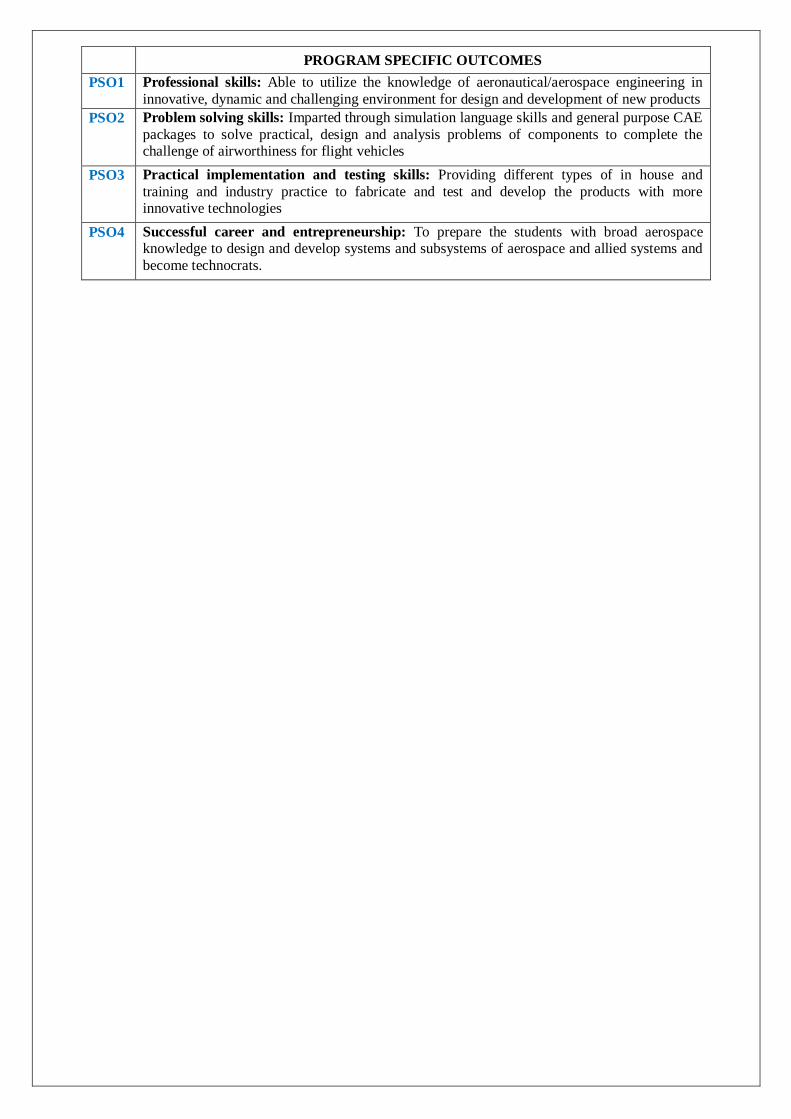
PROGRAM SPECIFIC OUTCOMES
PSO1 Professional skills: Able to utilize the knowledge of aeronautical/aerospace engineering in
innovative, dynamic and challenging environment for design and development of new products
PSO2 Problem solving skills: Imparted through simulation language skills and general purpose CAE
packages to solve practical, design and analysis problems of components to complete the challenge of airworthiness for flight vehicles
PSO3 Practical implementation and testing skills: Providing different types of in house and
training and industry practice to fabricate and test and develop the products with more innovative technologies
PSO4 Successful career and entrepreneurship: To prepare the students with broad aerospace knowledge to design and develop systems and subsystems of aerospace and allied systems and
become technocrats.

FLUID MECHANICS AND HYDRAULICS LAB SYLLABUS
S. No. List of Experiments Page
No.
I Caliberation of vent
urimeter and orificemeter 1
II Determination of pipe flow losses in rectangular and circular pipes 4
III Verification of Bernoullis theorem 6
IV Determination of Reynolds Number of fluid flow 9
V Study Impact of jet on Vanes 11
VI Performance test on centrifugal pumps 13
VII Performance test on reciprocating pumps 15
VIII Performance test on pelton wheel turbine 17
IX Performance test on Francis turbine 20
X Rate of discharge Flow through Wires 23
XI Flow through rectangular and V-Notch 25
XII Flow analysis of different shapes of mouth pieces 27

FLUID MECHANICS AND HYDRAULICS LABORATORY
OBJECTIVE:
The objective of this lab is to teach students, the knowledge of various flow meters and the concept of fluid mechanics. This lab
helps to gain knowledge on working of centrifugal pumps, positive displacement pumps,hydraulic turbines. Students will compare
the performance of various machines at different operating points.
OUTCOMES:
After completing this course the student must demonstrate the knowledge and ability to:
1. Understand the working of different fluid and hydraulic machines.
2. Understand the concept of pipe flow losses.
3. Verify the Bernoullis theorem
4. Determine the Reynolds number of flow.
5. Understand the Impact of jet on vanes.
6. Examine the centrifugal and reciprocating pumps.
7. Examine the Francis and Piston wheel turbine.
8. Analyze the flow through wires.
9. Analyze the flow through rectangular and V-notch.
10. Examine the flow through orifice mouth piece .

ATTAINMENT OF PROGRAM OUTCOMES & PROGRAM SPECIFIC
OUTCOMES
Expt.
No. Program Outcomes Attained
Program Specific Outcomes Attained
AERO
1 PO1, PO2, PO4, PO5, PO6, PO9, PO11, PO12 PSO1, PSO2, PSO3
2 PO1, PO2, PO4, PO5, PO6, PO9, PO11, PO12 PSO1, PSO2, PSO3
3 PO1, PO4, PO9, PO11, PO12 PSO1, PSO2, PSO3
4 PO1, PO2, PO4, PO9, PO11, PO12 PSO1, PSO2, PSO3
5 PO1, PO2, PO4, PO9, PO11, PO12 PSO1, PSO2, PSO3
6 PO1, PO3, PO4, PO5, PO9, PO11, PO12 PSO1, PSO2, PSO3
7 PO1, PO4, PO9, PO11, PO12 PSO1, PSO2, PSO3
8 PO1, PO4, PO9, PO11, PO12 PSO1, PSO2, PSO3
9 PO1, PO2, PO4, PO5, PO9, PO11, PO12 PSO1, PSO2, PSO3
10 PO1, PO3, PO4, PO5, PO9, PO11, PO12 PSO1, PSO2, PSO3
11 PO1, PO3, PO4, PO5, PO9, PO11, PO12 PSO1, PSO2, PSO3
12 PO1, PO3, PO4, PO5, PO9, PO11, PO12 PSO1, PSO2, PSO3

EXPERIMENT – I
CALIBERATION OF VENTURIMETER AND ORIFICEMETER
AIM:
To determine the coefficient of discharge of venturi meter and orifice meter.
APPARATUS:
A pipe provided with inlet and outlet and pressure tapping and venturi in between them, Differential u-tube manometer,
Collecting tank with piezometer, Stopwatch, Scale, A pipe provided with inlet and outlet and pressure tapping and Orifice in
between them
THEORY:
Venturi, the Italian engineer, discovered in 1791 that a pressure difference related the rate of flow could be created in
pipe by deliberately reducing its area of cross-section. The modern version of the venturi meter was first developed and employed
for measurement of flow of water by Clemens Herschel in 1886. Venturi meter continues to be the best and most precise
instrument for measurement of all types of fluid flow in pipes. The meter consists of a short length of gradual convergence throat
and a longer length of gradual divergence. The semi-angle of convergence is 8 to 10 degrees and the semi-angle of divergenceis3
to 5 degrees. By measuring the difference in fluid pressure becore and after throt the flow rate can be obtained from Bernoulli's
equation.
An orifice plate is a thin plate with a hole in it, which is usually placed in a pipe. When a fluid passes through the orifice,
its pressure builds up slightly upstream of the orifice, but as the fluid is forced to converge to pass through the hole, the velocity
increases and the fluid pressure decreases. A little downstream of the orifice the flow reaches its point of maximum convergence,
afterd that, the flow expands, the velocity falls and the pressure increases. By measuring the difference in fluid pressure across
tappings upstream and downstream of the plate, the flow rate can be obtained from Bernoulli's equation
PROCEDURE:
1. The pipe is selected for conducting venturimeter experiment.
2. The motor is switched on, as a result water will flow
3. According to the flow, the ccl4 level fluctuates in the U-tube manometer
4. The reading of H1 and H2 are noted
5. The time taken for 5 cm rise of water in the collecting tank is noted
6. The experiment is repeated for various flow in the same pipe
7. The co-efficient of discharge is calculated
8. The same procedure is followed for conducting orifice experiment
Fig.1

Fig.2 Venturimeter
Fig.3 Orifice meter
TABULARCOLUMN:
VENTURIMETER:
S.NO Manometric head Time taken for h cm
raise of water in tank t
Theoretical
Discharge (Qt)
m3/sec
Actual
Discharge
(Qa) m3/sec
Coefficient of
discharge
Cd = Qa/Qt h1 h2 hw

ORIFICEMETER:
S.NO Manometric head Time taken for h cm
raise of water in tank t
Theoretical
Discharge (Qt)
m3/sec
Actual
Discharge
(Qa) m3/sec
Coefficient of
discharge
Cd = Qa/Qt h1 h2 hw
CALCULATIONS:
t = Time taken for h cm raise of water in tank
h1= Manometric head in first limb m
h2 = Manometric head in second limb m
hw = Venturi head in terms of flowing liquid m
= (h2-h1) × {Specific gravity of ccl 4
specific gravity of water-1}
Specific gravity of carbon tetra chloride (ccl4) = 1.6
Specific gravity of water = 1
Diameter of the pipe = 4 cm
Diameter of the throat = 2.4 cm
Area of collecting tank = 50×50 cm2
Theoretical Discharge (Qt) = K× ℎ m3/sec
K=𝑎1×𝑎2× 2𝑔
𝑎12−𝑎22
a1=area of cross section of pipe
a2=area of cross section of pipe at throat
Actual Discharge (Qa) = [Volume of water collected in tank/time taken to collect water]
= [Area of tank × height of water collected in tank]/ t
Coefficient of discharge Cd = Qa/Qt
PRECAUTIONS:
RESULT:

Viva questions:
1. What is discharge?
2. What is continuity equation?
3. Write Bernoulli’s equation?
4. Give formula for experimental discharge?
5. What is coefficient of discharge?
6. Derive expression for theoretical discharge?

EXPERIMENT - II
DETERMINATION OF PIPE FLOW LOSSES IN RECTANGULAR AND CIRCULAR PIPES
AIM:
To determine the Darcy's friction factor (f) of the given pipe
APPARATUS:
A pipe provided with inlet and outlet and pressure tapping, Differential u-tube manometer, collecting tank with
piezometer, Stopwatch, Scale.
DESCRIPTION:
When the fluid flows through a pipe the viscosity of the fluid and the inner surface of the pipe offer resistance to the
flow. In overcoming the resistance some energy of the flowing fluid is lost. This is called the major loss in pipe flow. Boundary
roughness, which has little significance in laminar flow, plays an important role in turbulence. This, together with transverse
momentum exchange of fluid particles due to the perpetual turbulent intermixing, are the main sources of tangential or shear
stresses in turbulent flow. Various equations have been proposed to determine the head losses due to friction. These equations
relate the friction losses to physical characteristics of the pipe and various flow parameters.
PROCEDURE:
1. The pipe is selected for doing experiments
2. The motor is switched on, as a result water will flow
3. According to the flow, the mercury level fluctuates in the U-tube manometer
4. The reading of H1 and H2 are noted
5. The time taken for 5cm rise of water in the collecting tank is noted
6. The experiment is repeated for various flow in the same pipe
7. The co-efficient of discharge is calculated
Fig.4 SCHEMATIC DIAGRAM

TABULARCOLUMN:
RECTANGULAR PIPE:
S.NO Manometric head Time taken for h cm raise
of water in tank t sec
Discharge
(Q) m3/sec
Velocity (v)
m/sec
Friction factor
(f)
h1 h2 hf
CIRCULAR PIPE:
S.NO Manometric head Time taken for h cm raise
of water in tank t sec
Discharge
(Q) m3/sec
Velocity (v)
m/sec
Friction factor
(f)
h1 h2 hf
CALCULATIONS:
Friction factor (f) = 2 x g x D x hf
4l x v2 Where,
g = Acceleration due to gravity (m / sec2)
D for circular pipe =4x𝑐𝑟𝑜𝑠𝑠 𝑠𝑒𝑐𝑡𝑖𝑜𝑛𝑎𝑙 𝑎𝑟𝑒𝑎
𝑤𝑒𝑡𝑡𝑒𝑑 𝑝𝑒𝑟𝑖𝑚𝑒𝑡𝑒𝑟 =4x
𝜋𝑟2
𝜋𝑑=d
d= Diameter of the pipe = 2cm
D for squarer pipe = 4x𝑐𝑟𝑜𝑠𝑠 𝑠𝑒𝑐𝑡𝑖𝑜𝑛𝑎𝑙 𝑎𝑟𝑒𝑎
𝑤𝑒𝑡𝑡𝑒𝑑 𝑝𝑒𝑟𝑖𝑚𝑒𝑡𝑒𝑟=4x
𝑤xh
2x w+h
w= 2cm ,width of pipe, h= 2cm , height of pipe(for a square )
l = Length of the pipe = 200cm
v = Velocity of liquid following in the pipe (m / s)
hf = Loss of head due to friction (m)
= (h2-h1) × { Specific gravity of Hg
specific gravity of water - 1} Where

h1 = Manometric head in the first limbs
h2 = Manometric head in the second limbs
Actual Discharge Q = A x h
t (m3 / sec)
Where
A = Area of the collecting tank (m2)
h = Rise of water for 5 cm (m)
t = Time taken for 5 cm rise (sec)
Also
Q=Velocity in the pipe X Area of the pipe
= v a
V = Q/a
PRECAUTIONS:
RESULT:
Viva questions:
1. Derive Darcy’s equation? 2. Draw and explain pipe friction apparatus with neat sketch?
3. Write a formula for minor loses and major loses of pipe?
4. Write a formula for pressure head H?
5. What is area of wetted perimeter?

EXPERIMENT-III
VERIFICATION OF BERNOULIS THEOREM
AIM:
To verify the Bernoulli’s theorem.
APPARATUS:
A supply tank of water, a tapered inclined pipe fitted with no. of piezometer tubes point, measuring tank, scale, and stop
watch.
THEORY:
Bernoulli’s theorem states that when there is a continues connection between the particle of flowing mass liquid, the total
energy of any sector of flow will remain same provided there is no reduction or addition at any point. I.e. sum of pressure head
and velocity head is constant.
PROCEDURE:
1. Open the inlet valve slowly and allow the water to flow from the supply tank.
2. Now adjust the flow to get a constant head in the supply tank to make flow in and outflow equal.
3. Under this condition the pressure head will become constant in the piezometer tubes. Note down piezometer readings.
4. Note down the quantity of water collected in the measuring tank for a given interval of time.
5. Compute the area of cross-section under the piezometer tube.
6. Compute the values of velocity head and pressure head.
7. Change the inlet and outlet supply and note the reading.
8. Take at least three readings as described in the above steps.
Fig.5 SCHEMATIC DIAGRAM

Fig.6 Throat
TABULARCOLUMN:
S.NO Pizeometer
Reading
time for
5cm rise
Discharge
Q m3/sec
Pressure
Head m
Velocity
Head m
Datum
head m
Total Head
S.NO Pizeometer
Reading
time for
5cm rise
Discharge
Q m3/sec
Pressure
Head m
Velocity
Head m
Datum
head m
Total Head

S.NO Pizeometer
Reading
time for
5cm rise
Discharge
Q m3/sec
Pressure
Head m
Velocity
Head m
Datum
head m
Total Head
CALCULATIONS:
Pressure head = P
ρg m
Velocity head = v2
2g m
Datum head = Z = 0 m (for this experiment)
Velocity of water flow = v
Q (Discharge) = [Volume of water collected in tank/time taken to collect water]
= [Area of tank × height of water collected in tank]/ t m3/sec
Also
Q= velocity of water in pipe × area of cross section = v × Ax m3/sec
Area of cross section (Ax) = At + [(Ai−At)×Ln
L] m2
At = Area of Throt
Ai = Area of Inlet
Dia of throt = 25mm
Dia of inlet = 50mm
Ln= distance between throt and corresponding pizeometer
L=length of the diverging duct or converging duct = 300mm
Distance between each piezometer = 75mm
Total Head = 𝑃
ρg +
v2
2g + Z
PRECAUTIONS:
RESULT:
Viva questions:
1. Write Bernoulli’s equation?
2. What are assumptions of Bernoulli’s equation?
3. Write Euler’s equation?
4. Explain about a C.D nozzle?
5. What is pitot static tube, and peizometer?

EXPERIMENT-IV
DETERMINATION OF REYNOLDS NUMBER OF FLUID FLOW
AIM:-
To find critical Reynolds number for a pipe flow.
APPARATUS :-
Flow condition inlet supply, elliptical belt type arrangement for coloured fluid with regulating valve, collecting tank.
FORMULA :-
Reynolds No = Inertia force/Viscous force
Reynolds Number:- It is defined as ratio of inertia force of a flowing fluid and the viscous force of the fluid. The expression for Reynolds number is obtained as:-
Inertia force (Fi) = mass . acceleration of flowing
= δ. Volume. Velocity/ time = δ. +5*3L4
27L4Velocity
= δ.area .Velocity . Velocity = δ.A .V2
Viscous force (Fv) = Shear stress . area
= τ. A
= μ. du/dy . A
= VA/τ
By definition Reynolds number:-
Re= Fi/Fu
= δAV2/μ/t.A
= V.L /μ/s
= V.L /v { v = μ/ ρis kinematics viscosity of the fluid } In case of pipe flow, the linear
dimension L is taken as dia (d) hence Reynolds number for pipe flow is :-
Re = V .d /v or
Re = ρVd /v
PROCEDURE:-
1. Fill the supply tank some times before the experiment.
2. The calculated fluid is filled as container.
3. Now set the discharge by using the valve of that particular flow can be obtained.
4. The type of flow of rate is glass tube is made to be known by opening the valve of dye container.

5. Take the reading of discharge for particular flow.
Using the formula set the Reynolds no. for that particular flow, aspect the above procedure for all remaining flow
OBSERVATION:-
Type Time Discharge
Q=m3/3 Re=4Q/πΔV initial Final Difference Volume
PRECAUTIONS:-
RESULT:-
Viva questions
1. Reynolds number importance?
2. Describe the Reynolds number experiments to demonstrate the two type of flow?
3. Define laminar flow, transition flow and turbulent flow?

EXPERIMENT-V
IMPACT OF JETS ON VANES
AIM :
To find the coefficient of impact of jet on vanes.
APPARATUS:
Impact of jet on vanes experimental test rig, Flat vane, curved vane, Dead weights, stop watch.
THEORY:
A jet of fluid emerging from a nozzle has some velocity and hence it possesses a certain amount of kinetic energy. If the
jet strikes an obstruction placed in its path, it will exert force on obstruction. This impressed force is known as impact of jet and
it is designated as hydrodynamic force, in order to distinguish it from the force due to hydrostatic pressure. since a dynamic
force is exerted by virtue of fluid motion, it always involves a change of momentum, unlike a force due to hydrostatic pressure
that implies no motion.
PRINCIPLE:
The impulse momentum principle may be utilized to evaluate the hydrodynamic force exerted on a body by a fluid jet.
(1) When jet strikes a stationary Flat vane
In this case the flat vane is stationary and jet strikes on it at the middle and then splits in two parts leaves the corners
tangentially so
F=ρav2
(1+cosѳ)
The force of Impact will be maximum if the angle of declination is ѳ=90°
For Flat vane
For curved vane=
PROCEDURE:
1. Fix the vane to be tested inside the testing chamber by opening then transparent door provided. Close the door and tighten
the lock.
2. Note the initial reading on the scale.
3. Open the inlet water. The water jet from the nozzle strikes on vane gets deflected and drains back to collecting tank.
4 .Close the collecting tank drain valve and note down the time taken for 2cm rise in water level in the collecting tank.
Open the drain valve.
5. Add dead weight to bring the pointer back to the initial reading on the scale. Note down the dead weights.
6. Repeat the experiment for different flow rates by adjusting the position of the inlet valves and for different vanes.
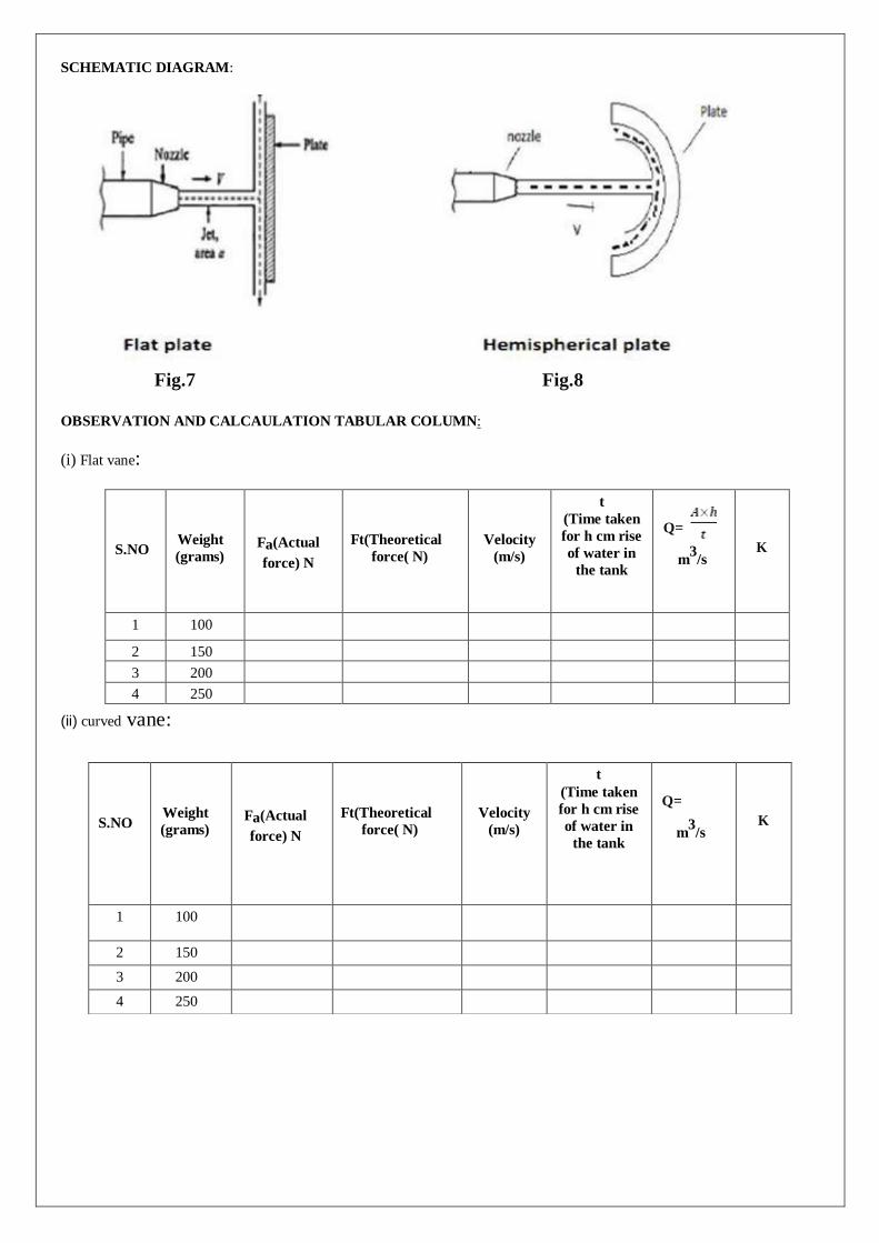
SCHEMATIC DIAGRAM:
Fig.7 Fig.8
OBSERVATION AND CALCAULATION TABULAR COLUMN:
(i) Flat vane:
S.NO
Weight
(grams)
Fa(Actual
force) N
Ft(Theoretical
force( N)
Velocity
(m/s)
t
(Time taken
for h cm rise
of water in
the tank
Q=
m3/s
K
1 100
2 150
3 200
4 250
(ii) curved vane:
S.NO
Weight
(grams)
Fa(Actual
force) N
Ft(Theoretical
force( N)
Velocity
(m/s)
t
(Time taken
for h cm rise
of water in
the tank
Q=
m3
/s
K
1 100
2 150
3 200
4 250

CALCULATIONS:
Theoretical force (N): Ft= ρav2(1+cosθ) For Flat
vane(θ=90)=
For curved vane= Where
diameter of nozzle = 1cm
Area of collecting tank= m3/s
Where A= Area of collecting tank m2
R=rise in water level. m
Coefficient of impact on vanes=
PRECAUTIONS:
RESULT:
The coefficient of impact of jet on vanes for Flat vane is .
The coefficient of impact of jet on vanes for Curved vane is .
Viva questions:
1. Define the terms impact of jet and jet propulsion?
2. Find the expression for efficiency of a series of moving curved vane when a jet of water strikes
the vanes at one of its tips?

EXPERIMENT-VI
PERFORMANCE TEST ON CENTRIFUGAL PUMP
AIM :-
To find the efficiency and draw the performance curves of centrifugal pump.
APPARATUS:
Centrifugal pump test rig, energy meter to measure the input electrical energy, pressure gauges (Suction
and delivery), stop watch.
THEORY:
The pump which raises water from lower level to higher level by the action centrifugal force is known as
centrifugal pump. The pump lifts water because of atmospheric pressure acting on the surface of the water. A
centrifugal pump is rotodynamic pump that uses a rotating impeller to increase the pressure of the fluid. It works by
rotational kinetic energy, typically from an electric motor to an increase the static fluid pressure. They are
commonly used to move liquid through a piping system.
Fluid enters axially through the middle portion of the pump call the eye, after which it encounters the rotating
blades. It acquires tagential and radial velocity by the momentum transfer with impeller blades and acquires
additional radial velocity by centrifugal force.
PROCEDURE
1.Prime the pump, close the delivery valve and switch on the unit.
2.Open the delivery vlave and maintain the requird delivery head.Note the reading.
3.Note the corresponding suction head pressure reading..
4.Measure the area of the collecting tank.
5.Close the drain the valve and note down the time taken for 10cm rise of the water level in the collecting tank.
6.For different delivery heads repeat the experiment.
7.For every set of reading note the time taken for 10 revelutions of Energy meter
Fig.9

OBSERVATION & CALCULATION TABULAR COLUMN:
CALCULATIONS:
The total effective head H in meters of Working of centrifugal pump
Total head
H=Hs+Hd+Z
Since the delivery pressure is in kg/cm2 and suction gauge pressure are in mm of Hg the total head
developed by the pump to be converted in to meters of water column.
Where Hd=Delivery head
Hs =Suction head
Z= Friction loss
Hs= m
Hd=Pdx9.81x102
m
9.81x1
000
Friction loss Z=2.2 m
Note: The velocity and the loss of head in the suction pipe are neglected
We know the discharge Q= m3/s
The work done by the pump is given by
KW Output power Po = ρQgH KW
1000
Input power Pi= 3600xN
KW
ExtE
E- Energy meter constant=150
tE=time for 3 revolutions of Energy meter.
N-no of Revolutions.
The efficiency of the centrifugal pump=
Ƞ=Po/Pi x100%.
S.NO
Pressure
gauge
reading
Pd
(Kg/cm2
)
Vacuum
gauge
reading
mm of
Hg(Ps)
Time for
3 rev of
Energy
meter
seconds
(te)
Time for 10
cm rise in
collecting
tank (t)
seconds
Discharge
(Q) m3/sec
Input
Power
Pi
K
W
Output
Power
Po
K
W
Efficien
cy%
1 1
2
3
4

24
GRAPHS: 1) Plot Pi and Po versus Speed N
2) Head versus Speed N
3) Speed versus Efficiency.
4) Head vs Discharge
PRECAUTIONS: RESULTS:
Viva Questions:
1.What is a pump?
2.What is a centrifugal pump?
3.what are forces involved in impeller? 4.What is priming

EXPERIMENT-VII
PERFORMANCE TEST ON RECIPROCATING PUMP
AIM: To study the performance characteristics of Reciprocating pump and to find slip.
APPARATUS :
Reciprocating test Rig, Pressure gauges at the inlet and delivery pipes, Energy meter to measure the input electrical
energy, stopwatch ,Tachometer.
THEORY:
Reciprocating pumps are positive displacement pump as a definite volume of liquid is trapped in a chamber which
is alternatively filled from the inlet and empited at a higher pressure through the discharge.
The fluid enters a pumping chamber through an inlet and is pushed out through outlet valve by the action of piston. They
are either single acting independent suction and delivery strokes or double acting suction and delivery both the directions.
Reciprocating pumps are self priming pumps and are suitable for very high head at low flows.They deliver reliable
discharge flows and is often used for metering duties because of constancy of flow rate.
DESCRIPTION:
It consist of a double action reciprocating pump of size 25x20mm with a air vessel coupled to 1HP, 1440Rpm,
collecting tank with a piezometer.
PROCEDURE:
1.Keep the delivery valve open and switch on pump slowly close the delivery valve and maintain a constant head.
2.Note the delivery and suction pressure gauge reading.
3.Note the time for 10 revolutions of Energy meter.
4.Note the time for 10cm rise in water level in collecting tank.
5.Note the speed of the pump.
5.Repeat the test for 4 other different head.
OBSERVATION &CALCULATION TABULAR COLUMN:
S.NO Pressure
gauge
reading Pd
(Kg/cm2
)
Vacuum
gauge
reading mm
of
Hg(Ps)
Time for 3
rev of
Energy
meter
(te)sec
Time for
10 cm rise
in collecting
tank
(t)sec
Speed
NP
Rpm
Discharge
(Q) m3
/sec
Input
Power
Pi
KW
Output
Power Po
KW
η
%
1
2
3
4
5

CALCULATIONS:
Stroke length of the pump (L) =0.045m
Bore (d) = 0.04m
Piston area (a) = (π/4) × (0.04)2
Area of the collecting tank (A) = 50 X 50 cm2
NP = speed of mortar in rpm
To find the percentage of slip = × 100
Qt = theoretical discharge = m/sec
Qa = Actual discharge = Q= m/sec
A = Area of the collecting tank
t = time for (h) rise in water level.
To find the overall efficiency of the pump = Po/Pi
Input power Pi = Kw
Where
N = Number of blinks of energy meter disc
E = Energy meter constant = 1600 (rev / Kw hr)
T = time taken for ‘Nr’ revolutions (seconds)
Output power Po = Kw
Where,
ρ = Density of water = 1000 (kg / m³)
g = Acceleration due to gravity = 9.81(m / s2
) H = Total head of water (m)
H = suction head (Hs) + delivery Head (Hd) + Datum Head
Where Hd = delivery head = Pdx9.81x104
m
ρxg
Hs = suction head m
Z= Friction loss = 2.2 m
GRAPHS:
1. Actual discharge Vs Total head
2. Actual discharge Vs Efficiency
3. Actual discharge Vs Input power
4. Actual discharge Vs Output power
RESULT:
EXPERIMENT VIII
PERFORMANCE TEST ON PELTON WHEEL
AIM:
To draw the following characterstic curves of pelton wheel under constant head.
APPARATUS :
1. Venturimeter 2. Stopwatch 3. Tachometer 4. Dead weight
DESCRIPTION:
Pelton wheel turbine is an impulse turbine, which is used to act on high loads and for generating electricity. All the
available heads are classified into velocity energy(i.e) kinetic energy by means of spear and nozzle arrangement. Position of the
jet strikes the knife-edge of the buckets with least relative resistances and shocks. While passing along the buckets the velocity
of the water is reduced and hence an impulse force is supplied to the cups which in turn are moved and hence shaft is rotated.
Pelton wheel is an impulse turbine which is used to utilize high heads for generation of electricity. It consists of a runner
mounted on a shaft.
To this a brake drum is attached to apply brakes over the speed of the turbine. A casing is fixed over the runner. All the
available head is converted into velocity energy by means of spear and nozzle arrangement. The spear can be positioned in 8
places that is, 1/8, 2/8, 3/8, 4/8, 5/8 6/8, 7/8 and 8/8 of nozzle opening. The jet of water then strikes the buckets of the Pelton
wheel runner. The buckets are in shape of double cups joined at middle portion. The jet strikes the knife edge of the buckets with
least resistance and shock. The jet is deflected through more than 160˚ to 170˚. While the specific speed of Pelton wheel changes
from 10 to 100 passing along the buckets, the velocity of water is reduced and hence the impulsive force is supplied to the cups
which in turn are moved and hence the shaft is rotated. The supply of water is arranged by means of centrifugal pump. The
speed of turbine is measured with tachometer.
CONSTRUCTIONAL FEATURES:
CASING: casing is fabricated from MS Plates with integralbase is provided.
RUNNER: Runner is made of steel and machined precisely and fixed to horizontal shaft.The bucket resembles to a
hemispherical cup with a dividing wall inits center in the radial direction of the runner.The buckets are arranged uniformly on
the periphery of the runner.The compact assembly Nickel plated to prevent corrosion and to have a smooth finish.
NOZZLE ASSEMBLY: Nozzle assembly consist essentially of a spear, a hand wheel and the input pipe.The water from the
supply pump is made to pass through the nozzle before it enters the turbine.shaft is made of stainlesssteel and carries the runner
and brake drum.
Brake arrangement :Brake arrangement consist of machined and polished brake drum, cooling water pipes internal water
scoop, discharge pipe spring balance, discharge pipe,spring balance, belt arrangement supporting stand.
Base frame: Base frame is made is made of MS channel for sturdy construction and it is an integral part of the casing.
TECHANICAL SPECIFICATIONS: TURBINE:
1. Rated supply head-40m.
2. Discharge-660 Lpm.
3. Rated speed-800 Rpm.
4. Runner outside diameter-300m.
5. No of pelton buckets- 20 No’s
6. Brake drum diameter-300m
7. Power output-3.5
HP SUPPLY PUMP:
Centrifugal pump Multista
FLOW MEASURING UNIT:
Venturimeter
Convergent diameter -65mm.
Throat diameter-39mm.
Pressure guage -7 kg/cm2

PROCEDURE:
1. Gradually open the delivery valve of the pump.
2. Adjust the nozzle opening at about ½ th of the opening by oerating the spear valve by Hand wheel.
3. The head should be made constant by operating the delivery valve and the head should be maintained at constant value.
4. Observe the speed of the turbine using the tachometer.
5. Observe the readings of h1 and h2 corresponding the manometric fluid in the two limbs,which are connected to the
venturimeter.
6. Adjust the load on the brake drum;note the speed of the turbine using tachometer and spring balance reading.
7. Repeat the experiment for different loadings
Fig.10

Fig.11 schematic representation of Pelton wheel

S.N
O
Gate
open
ing
Pressure
Gauge
(Kg/cm2)
Vacuu m
Gauge
(mm of
Hg)
Manometer
Readin
g
Speed of
Break drum
Dynamomet
er
‘N’(Rpm)
Spring
Balance
Power
Output
(P
(KW)
Power
Input
(P )
(KW)
Efficiency
‘ Ƞ’
(%) h1(cm) h2(cm) T1(kg) T2(k
g)
1
2
3
4
OBSERVATION & CALCULATION TABULAR COLUMN(MECHANICAL LOADING):
o) i
OBSERVATIONS:
Venturimeter inlet Diameter, d1= 65 mm. Venturimeter
inlet area, a1 = . Venturimeter throat
diameter ,d2= 39mm. Venturimeter throat area, a2 =
.
Speed (N)
S.NO
Load
(KW)
Voltammeter
( V)
Current
(A)
Power
(KW)
Speed of Break Drum
Dynamometer ‘N’ Rpm
Efficiency
‘Ƞ’ (%)
1
2
3
4
5

Diameter of brake drum , D = 300mm
CALCULATIONS:
Inlet Pressure, P = Kg/cm2
Vaccum gauge =mm of Hg
Q= Discharge Q = Cd
Where Cd -0.98
h-Manometric difference = h1-h2 [ -1]
where s1-specific gravity of mercury-13.6
s2-specific gravity of water-1
Head, H = head available at the turbine (pressure head in terms of water column).
Output power (Po) = watts
Input power (Pi) = (ρ×g×Q×h) W
T = (T1-T2) ×g × radius of break drum N-m
T1=load applied on Brake drum dynamometer(Kg). T2=load
applied on Brake drum dynamometer(Kg). Radius Of break drum
= 0.15m.
N = speed of Brake drum Dynamometer (Rpm). Efficiency of
the turbine ηm%= Po/Pi
Electrical efficiency = ηe% = po / Pi
po= electrical output = V × I w.
GRAPHS:
1. Speed vs. efficiency
2. Discharge vs. power input
3. Input power vs. Speed
4. Output power vs speed
5. Head vs Speed
PRECAUTIONS:
RESULT:
Viva questions:
1.Classify turbines.
2.Pelton wheel is which type of turbine.
3.what is input energy given to turbine? What are main components of Pelton turbine?
4. Draw velocity diagrams (at inlet and outlet) for Pelton blade
5. Why is Pelton turbine suitable for high heads?

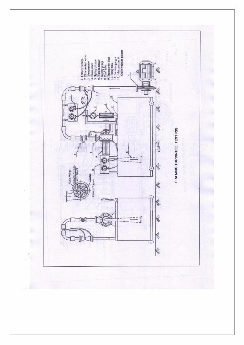
EXPERIMENT -IX PERFORMANCE TEST ON FRANCIS TURBINE
AIM:
To conduct load test on Francis turbine and to study the characteristics of Francis turbine.
APPARATUS :
U-tube manometer, Tachometer.
TECHANICAL SPECIFICATION:
Supply pump: Rated head-20 m,
Discharge-2000 Lps.
Normal speed-1440 Rpm
Power required-11.2KW
Size of the pump-100x100 mm.
Pump Type: Centrifugal High speed single suction volute.
Francis turbine: Rated supplyhead-20 m.
Discharge-2000 Lps.
Rated speed-1250 Rpm.
Runner diameter-150 mm.
Number of guide vanes-8.
Brake drum diameter-300 mm.
Flow measuring unit:
Manometer –U-tube differentialcolumn.
Size of venturimeter-100 mm
Throat diameter- 60mm.
DESCRIPTION:
The water from the penstock enters a scroll casing which completely surrounds the runner.The purpose of the casing is to
provide an even distribution around the circumference of the turbine runner, maintaining an constant velocity of water.
In order to keep the velocity of water constant throught its path around the runner, the cross-sectional area of casing is
gradually decreased.The casing is made up of material depending upon the pressure nto which it is subjected From the scroll
casing the water passes through the speed ring consist of upper and lower ring Held together by a series of fixed vanes called
stay vanes. The number of stay vanes is usually taken as half number of guide vanes.
The speed ring has two functions to perform.It directs the water to scroll casing to guide vanes Francis turbine consists of
runner mounted on a shaft and enclosed in a spiral casing with guide vanes. The cross section of flow between the guide vanes
can be varied, known as gate opening. It can be adjusted ¼, ½, ¾, or full gate opening. A brake drum is fixed to the turbine
shaft.
By means of this drum the speed of the turbine can be varied. The discharge can be varied by operating a throttle valve on the
pipe line. The water after doing work leaves the turbine through a draft tube and flows down into the tail race. A Venturimeter
is fitted to the pipe for measuring discharge.
PROCEDURE:
1. Keep the guide vane at required opening (say ½ th)
2. Prime the pump if necessary.
3. Close the main gate valve and start the pump.
4. Open the gate valve for required discharge
5. Open the brake drum cooling water gate valve for cooling the brake drum.
6. Note the Venturimeter pressure gauge readings
7. Note the inlet pressure gauge & outlet vacuum gauge readings
8. Note down applied weights spring balance.

9. Measure the turbine runner speed in rpm with tachometer.
10. Repeat the experiment for different loadings.
OBSERVATIONS:
Venturimeter inlet
Diameter, d= 100mm.
Venturimeter throat diameter d= 60mm.
Speed (N) = _ Rpm
Radius of brake drum, R = 0.15 m
CALCULATION:
Inlet Pressure guage P = Kg/cm2
Outlet Vacuum guage V = mm of Hg.
Head, H = head available at the turbine (pressure head in terms of water column)
Q = Cd m3/s
Q = Cd m3/s
Where Cd -0.98
Power input [Pi]= ρQgH KW
1000
ρ-Density of water 1000kg/m3. Q- Flow rate m
3/s
g-Acceleration due to gravity.9.81m/s
H- Total head.
Power output [Po] = 2ΠNT KW
60x1000
N- speed of Brake drum dynamometer. Mechanical load
T= (T1-T2)x9.81x0.15 N-m.
Efficiency Ƞ= power output
Power input

S.N
O
Gate
open
ing
Pressure Gauge
(Kg/cm2)
Vacuu
m
Gauge
(mm of
Hg)
Manometer
Reading Speed of
Break
drum
Dynamomet
er
‘N’(Rpm)
Spring
Balance
Power
Output
(P)
(KW)
Power
Input
(P )
(KW)
Efficiency
‘ Ƞ’ %
h1(cm) h2(cm) T1(kg) T2(kg)
1
2
3
4
OBSERVATION & CALCULATION TABULAR COLUMN (MECHANICAL LOADING):

PRECAUTIONS:
RESULT:
MODEL GRAPHS:
1. speed vs. efficiency
2. Discharge vs. power input
3. Input power vs. Speed
4. Output power vs speed
Viva Question:
1.What is a reaction turbine?
2.what is difference between impulse and reaction turbine?
3.Specify the flow of the francis turbine.
4.what head francis turbine used?
5.what is purpose of draft tube in reaction turbine?
6.What is cavitation?

EXPERIMENT-XI
FLOW THROUGH NOTCHES
AIM:
To determine the flow through notches.
APPARATUS:
Hydraulic bench, stop watch & Notch of different shape (Rectangular and Triangular)
DESCRIPTION:
In layman's terms, a Notch is defined as an obstruction. Notches are plates with sharp edged openings. They are primarily used for
flow measurement. Flow of liquid occurs over these Notches. Notches are used for measuring the flow rate of a liquid from
reservoirs or tanks. There are different types of notches, but for practical purposes most commonly used notches are usually
rectangular, Triangular or Trapezoidal in shape. The sheet of water discharged by a notch is called Nappe or Vein. An attempt has
been made to show the working principle and the calibration techniques adopted in developing the notches.
PROCEDURE:
1. Fix the plate having rectangular notch in the water passage of Hydraulic bench.
2. Turn the hydraulic bench on; water will accumulate in the channel.
3. When the water level reaches the Crest or sill of notch stop the inflow and note the reading, and design it as H1.
4. Restart the bench and note the volume and time of water that accumulates in the volumetric tank of bench, from this find
the discharge, and also note the height of water at this point.
5. Find H = H2 – H1 This will give you the head over the notch.
6. Find the width of the notch.
7. Take different readings by changing the discharge head over the notch, using the above procedure.
8. Plot a graph between Log10H and Log10Q and find K from graph equation.
Find Cd from the following formula. Cd = 2 / 3 x k / √2g x b
b = 3 cm
DIAGRAM:
Fig.12 FLOW THROUGH NOTCHES

TABULAR COLUMNS:
TRIANGULAR NOTCH :
RECTANGULAR NOTCH:
S.NO Initial
(cm)
Final
(cm)
Diff.
(H)
(cm)
ΔH
(cm)
CALCULATIONS:
S.NO Initial
(cm)
Final
(cm)
Diff.
(H)
(cm)
ΔH
(cm)

PRECAUTIONS:
RESULT:
Viva questions:
1. Derive expression for theoretical discharge?
2. Sketch and explain flow through notch apparatus?
3. What are the applications of square notch?
4. What is the application of flow through notch?
5. What are the units of discharge?

EXPERIMENT - XII
DETERMINATION OF CO-EFFICIENT OF DISCHARGE FOR
AN EXTERNAL MOUTH PIECE BY VARIABLE HEAD
METHOD
AIM:
To determine the coefficient of discharge of mouth pieces.
.APPARATUS REQUIRED:
1. collecting tank 2.Sump Tank
3.piezometer 4.Butterfly Valve
5.scale.
INTRODUCTION:
All openings cannot be considered as an mouth piece unless the water level on the upstream side is above the opening
.The purpose of the mouth piece is to measure the discharge. When the water comes out through the mouth piece , the water particles contracts to the minimum area called as the vena contracta. The diameter of the vena contracta is approximately
considered as the half the diameter of the mouth piece .However, to view the vena contracta the head should be very high and due
limitations an attempt has been made to study the process.
DESCRIPTION OF APPARATUS:
1) Water from the sump tank is sucked by the pump and is delivered through the delivery pipe to the collecting pipe
2) Over flow arrangement is provided to the collecting and over head tanks
3) Butterfly Valve is provided in measuring tank for instant close and release
4) the section and delivery can be controlled by means of control valves
5) Piezo meter with vinyl sticker scale is provided to measure the height of the water collected in measuring tan
6) The Equipment comes with accessories orifice and Mouthpieces each and no of different varieties
Fig.13 OPEN ORIFICE AND MOUTHPIECES

PROCEDURE: 1. Fill the sump tank with water to the specified level.
2. Place the mouth piece of study in the overhead tank. 3. Set the head by opening the required valve in the overhead tank
4. Close the main control valve and give necessary electrical connections
5. Switch on the supply pump starter after confirming the mains on indicator is glowing.
6. Open the main control valve slowly and steadily such that the required constant head is maintained
7. Measure the discharge in the collecting tank by closing the butterfly valve and taking the time for R cm raise
8. Open the butterfly valve after taking the readings
9. Repeat above steps for different orifices and heads.
10. Calculate the discharge, velocity and contraction coefficient using given formulae.
11. After finishing the experiment close the main control valve and switch off the pump starter and disconnect the electrical
connections.
12. Repeat the above step
OBSERVATIONS:
For Head =____________________m
S No
External
mouth piece
diameter Head Position
Time for R cm
rise of water (in
sec)
Cd
CALCULATIONS :
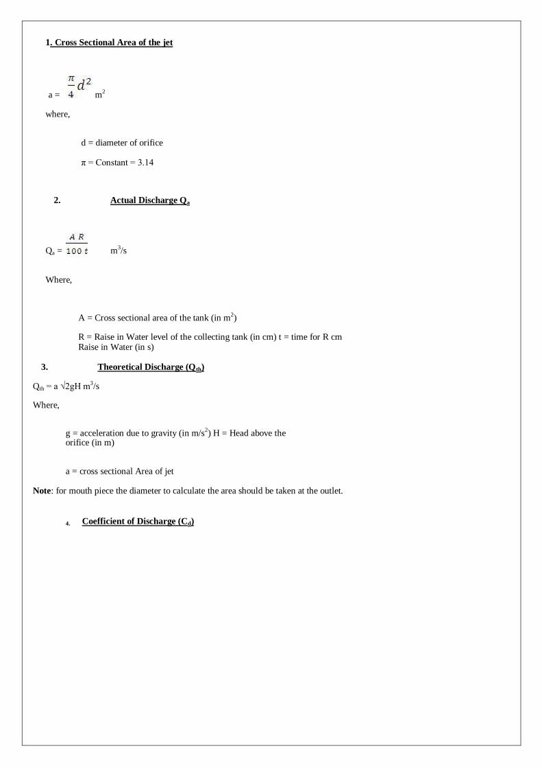
1. Cross Sectional Area of the jet
a = m2
where,
d = diameter of orifice
π = Constant = 3.14
2. Actual Discharge Qa
Qa = m3/s
Where,
A = Cross sectional area of the tank (in m2)
R = Raise in Water level of the collecting tank (in cm) t = time for R cm Raise in Water (in s)
3. Theoretical Discharge (Qth)
Qth = a √2gH m3/s
Where,
g = acceleration due to gravity (in m/s2) H = Head above the orifice (in m)
a = cross sectional Area of jet
Note: for mouth piece the diameter to calculate the area should be taken at the outlet.
4. Coefficient of Discharge (Cd)
PRECAUTIONS :
RESULT:
Viva questions:
1. Define Orifice?
2. Define Mouth piece?
3. Define vena contracta?
4. Define co efficient of velocity?