Embed Size (px)
Citation preview

AC1000 PAN & COVER AWNING ASSEMBLY INSTRUCTIONS
READ ALL INSTRUCTIONS CAREFULLY BEFORE STARTING THINGS TO CONSIDER BEFORE YOU BEGIN: *The door or window being covered must clear the understructure of the awning when fully open. *There should be 78” to 84” distance from the floor or slab to the bottom of the awning when installed over a door so there is room to walk under it without ducking. *Smaller awnings can be assembled on the ground and then attached to the building in one piece. *If columns or posts are necessary for support, they must be attached to a fixed surface or cemented in. IF INSTALLATION IS ON A BUILDING WITH….. *Wood or aluminum lap siding-attach mounting rail (flashing) directly under an overlap using 1 ¼” hex head screws at pre-punched locations. These are punched at 9” centers. *Aluminum siding with soft backer-it is important to locate the studs before attaching mounting rail (flashing). If the pre-punched holes do not line up with the studs drill new ones. Be sure to fill all the pre-punched holes with 1 ¼” screws to avoid any leakage. *Masonry-follow a mortar line. Drill 1 5/16” deep holes using a 1/4” drill bit at the pre-punched hole locations. Use a fiber or plastic plug and secure with 1 ¼” screws. Tools required Electric drill with 11/64” bit and ¼” bit, tape measure, level, hammer, metal snips, Phillips screw driver, 11/32” and 3/8” socket or wrench, caulking Step 1 Run caulking compound along the back of the mounting rail (Part A) that is facing the house, and attach using the correct application (from above).
SEE PARTS LIST ON PAGE 2.
Pg 1

Part A Part B Part CMounting Rail Left Side Starter Pan Left Side Louver Section
Part D Part E Part F8/32" x 3/8" Bolt and Nut Right Side Starter Pan Right Side Louver Section
Part G Part H Part I1-1/2" Lag Bolt Runner Bottom Pan
Part J Part K *Part LRunner Clips Top Pan 1/2" Self-Tapping Screw
*Part M *Part N *Part ORafter Brace Knee Brace Post Flange
* Notates parts that are sent only when required for larger Awnings.
AC1000 Awning Parts List
Pg 2

Step 2 Note: Step 2 and Step 3 must be done on the ground, and then the Awning can be attached to the Mounting Rail that was put on the House in Step 1. Gather the Left Louver Section (Part C), the Right Louver Section (Part F), and the Runner(s) (Part H). Place the Runner(s) (Part H), slots facing toward the front of the Awning, at pre-punched holes located on the Rafter of the two louver sections. Insert Bolts & Nuts (Part D) with the Bolt head on top and secure both sides.
Step 3 Working from left to right, attach the Left side Starter Pan (Part B) to the left side Louver Section (Part C): The edge of the Left side Starter Pan (Part B) overlaps the side of the Left side Louver Section (Part C). Connect them together using Bolt & Nut (Part D) beginning with the pre-drilled hole in the Starter Pan overlapping the slotted hole on the front side of the Louver Section. You will need to bend down the front valance section of the Starter Pan over the front of the Louver Section. Continue connecting them together by drilling holes (11/64” Bit) approximately every 12” along the overlapping lip of the starter pan and using Bolts & Nuts (Part D) to attach. Repeat with the Right side Starter Pan (Part E) and Right side Louver Section (Part F).
Pg 3

Step4 Attach the Left side Starter Pan/Louver Section you’ve just assembled to the Mounting Rail on House: Use Bolts & Nuts (Part D) in the pre-drilled hole(s) at the top of the Left side Starter Pan (Part B) into the pre-drilled hole(s) on the left end of the Mounting Rail (Part A). Repeat with the Right side Starter Pan / Louver Section connecting to the Right side of the Mounting Rail.
Step 5 Adjust the shim cup (on the bottom of each louver section) to hold the awning level against the House: use Lag Bolt (Part G) in the pre-drilled hole of the shim cup to secure to the house/structure. Then in order to secure the shim cup, drill out the Set Hole using a 11/64” bit and place the Bolt & Nut (Part D) through the Set Hole.
Pg 4
Step 6 Move to the next set of holes in the Mounting Rail (Part A). Attach a Bottom Pan (Part I) to the Mounting Rail (Part A) using Bolts & Nuts (Part D). Bend valances downward just slightly for now. Once all bottom pans are in place and secured to the flashing, bend the front valance sections the rest of the way to match starter pans.
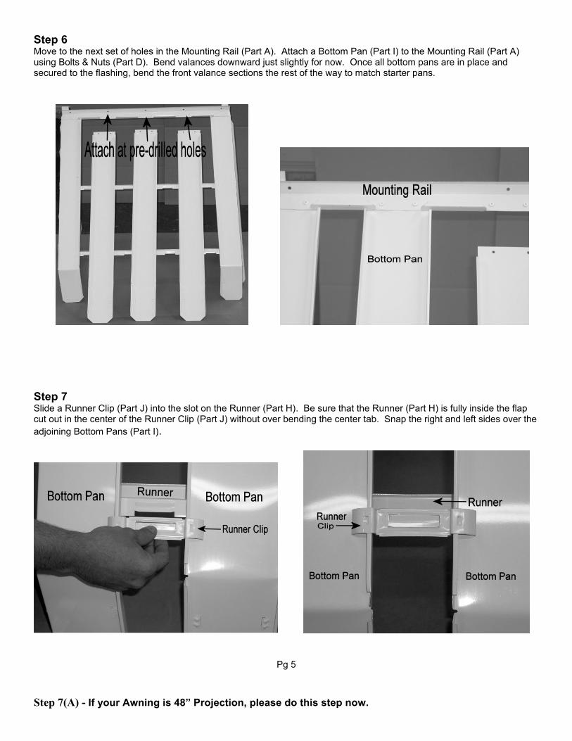
Step 7 Slide a Runner Clip (Part J) into the slot on the Runner (Part H). Be sure that the Runner (Part H) is fully inside the flap cut out in the center of the Runner Clip (Part J) without over bending the center tab. Snap the right and left sides over the adjoining Bottom Pans (Part I).
Pg 5
Step 7(A) - If your Awning is 48” Projection, please do this step now.

If your Awning is less than 48” Projection, please PROCEED TO STEP 8. In cases where projection is 48” and over and posts are necessary for support. First, install the supplied Rafter Brace (Part M) by attaching it to the house/structure, underneath the Mounting Rail (Part A), using Lag Bolt (Part G). Also attach the Rafter Brace (Part M) to the Runner(s) (Part H) using Self-Tapping Screws (Part L).
Step 7(B) Attach the Half-Moon Bracket to the Rafter Brace using Self-Tapping Screws (Part L). Plum the post in order to find where the Post Flange (Part O) will be placed. Secure the bottom flange to the floor through the center hole with the provided #14-10 x 1-1/2” lag screw. Measure the distance between the Half-Moon Bracket and the Post Flange (Part O) and cut the Post to this size, if necessary, with a hacksaw or power saw. Insert the post into the flange opening. Secure Post to Flange using 2 Self-Tapping Screws (Part L), one on each side. Also secure the post into the Half-Moon Bracket using 2 Self-Tapping Screws (Part L), one on each side.
. Pg 6
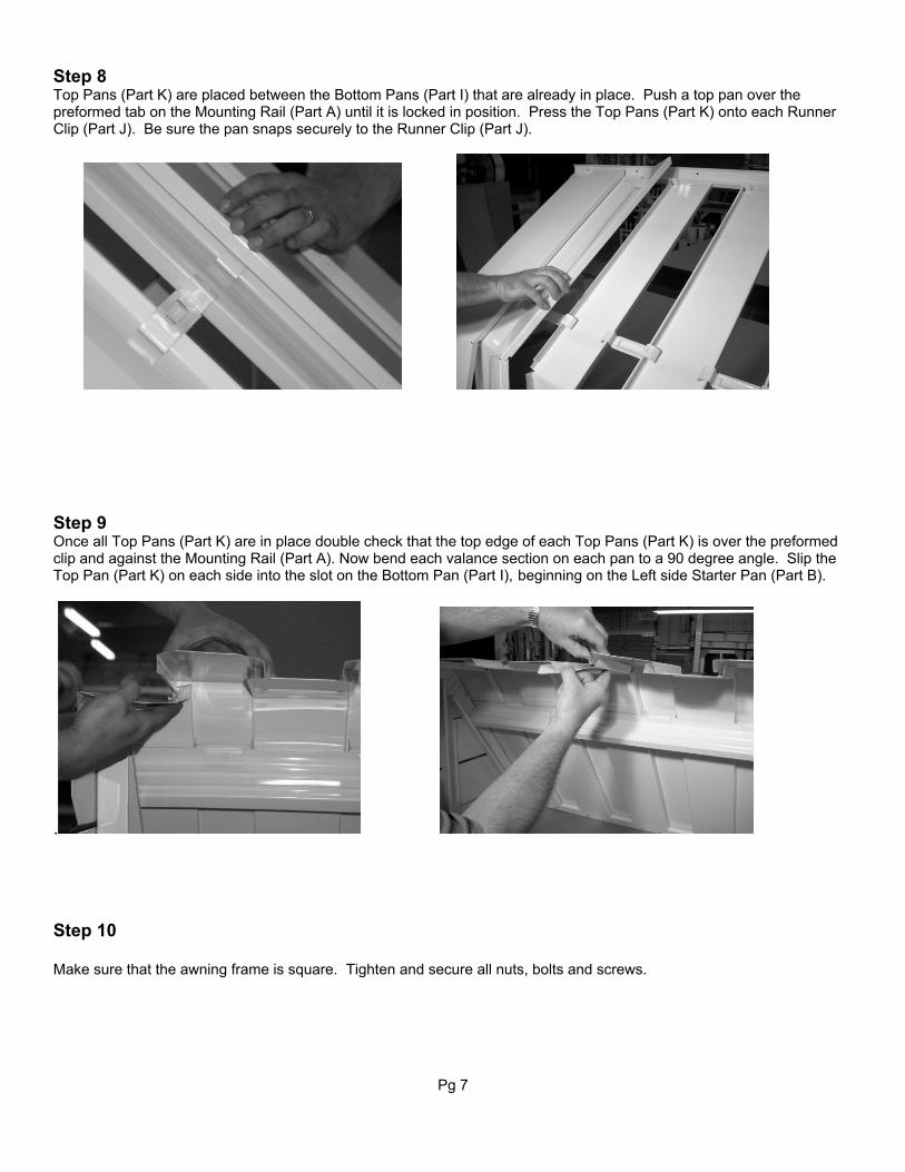
Step 8 Top Pans (Part K) are placed between the Bottom Pans (Part I) that are already in place. Push a top pan over the preformed tab on the Mounting Rail (Part A) until it is locked in position. Press the Top Pans (Part K) onto each Runner Clip (Part J). Be sure the pan snaps securely to the Runner Clip (Part J).
Step 9 Once all Top Pans (Part K) are in place double check that the top edge of each Top Pans (Part K) is over the preformed clip and against the Mounting Rail (Part A). Now bend each valance section on each pan to a 90 degree angle. Slip the Top Pan (Part K) on each side into the slot on the Bottom Pan (Part I), beginning on the Left side Starter Pan (Part B).
. Step 10 Make sure that the awning frame is square. Tighten and secure all nuts, bolts and screws.
Pg 7

OTHER PRODUCTS MANUFACTURED BY AGE CRAFT MFG :
Aluminum Railings (Commercial and Residential)
Speartop Fencing Pipe Rail (Schedule 40)
Structural Aluminum Columns (3 Styles)
Vinyl Railing Window Treatments
www.agecraftonline.com
AGE CRAFT AWNING (AC1000, EC101, AC4000) WARRANTY
For a period of One (1) Year from the date of purchase, Age Craft will repair or replace any Age Craft product which is defective in materials or workmanship. This warranty does not cover defects which result from misuse or failure to follow use and care instructions provided at the time of purchase. This warranty does not cover claims for incidental, remote, or consequential damages. Additionally, this warranty does not cover defects which are the result of improper or non-specified assembly or installation, nor does it cover defects in product assembly which are not made completely from Age Craft parts.
Pg 8