Embed Size (px)
Citation preview

Starting Guide


ADVANCE CONCRETE Starting guide
TABLE OF CONTENTS
INTRODUCTION .......................................................................................... 5 Advance Concrete ............................................................................... 5 Where to find information? ................................................................. 6
INSTALLATION ........................................................................................... 7 STARTING ADVANCE CONCRETE ........................................................... 7 ADVANCE CONCRETE USER INTERFACE .............................................. 7
Other important tools for using Advance .......................................... 9 3D MODEL ................................................................................................... 9
Accessing properties ........................................................................ 10 Project settings .............................................................................. 10
Creating a model ................................................................................ 11 Creating walls ................................................................................ 12 Using the UCS ............................................................................... 13 Creating columns........................................................................... 14 Creating beams ............................................................................. 15 Creating slabs ................................................................................ 17 Creating openings ......................................................................... 17 Opening libraries ........................................................................... 18 Automatically creating a new level ................................................ 19 Creating foundations ..................................................................... 21 Creating a polygonal slab opening ................................................ 22 Creating stairs ............................................................................... 22
DRAWING CREATION .............................................................................. 24 Dimensions......................................................................................... 26 Layouts ............................................................................................... 27
3

ADVANCE CONCRETE Starting guide
REINFORCEMENT ................................................................................... 28 Reinforcement drawing .................................................................... 29 Creating the reinforcement .............................................................. 29 3D viewer ........................................................................................... 34 Placing the reinforcement symbols ................................................ 35 Distribution dimensions ................................................................... 35 Lists .................................................................................................... 36
4

ADVANCE CONCRETE Starting guide
INTRODUCTION
This starting guide is a brief introduction to working with Advance Concrete, describing the basic Advance methodology and not meant to replace formal training.
The examples presented in this guide are generic for worldwide use and do not conform to local or specific company standards.
The 3D model chapter describes the main Advance Concrete objects used to create a small building. The 3D model is created using a 1:1 scale. The model contains information about dimensions, objects, and attributes from which drawings are created as described in the Drawing Creation chapter. The Layouts chapter describes how to create layouts using the drawings created in the Drawing Creation chapter. The Reinforcement chapter describes how the Advance Reinforcement module works. Since not all Advance Concrete tools are described in this guide, refer to the Help for more details on all commands and parameters.
Advance Concrete Advance Concrete is a leading edge concrete construction application. It provides a simple user-friendly working environment for creating 3D structural models from which drawings are created. The three dimensional model is created using Advance Concrete intelligent objects and stored in a drawing (in DWG format). The Advance model forms the basis of the 3D construction.
5

ADVANCE CONCRETE Starting guide
Once a model is complete, Advance Concrete creates all structural and reinforcement drawings using a large selection of view production tools, dimensions, locations, symbols, and automatic layout functions. Layouts are created from the created drawings.
All software tools described in this guide and all remarks related to the product pertain only to the Advance Concrete suite and for reading simplification only the generic name Advance is used.
Where to find information? Advance has a help system that offers step-by-step instructions for every function. To access the help:
• AC Tools tab, Help panel: click . • Command line: grtchelp
6

ADVANCE CONCRETE Starting guide
INSTALLATION
To successfully install Advance certain requirements have to be met. For more details, see http://www.autodesk.com/adv-concrete-systemreq-2015-enu.
STARTING ADVANCE CONCRETE To start Advance Concrete
– Double click the Advance Concrete icon on the desktop. or
– On the Windows task bar, click , then select All Programs > Autodesk > Advance Concrete 2015 > Advance Concrete 2015. ADVANCE CONCRETE USER INTERFACE Advance Concrete is fully integrated into AutoCAD®. Advance Concrete panels are added to the AutoCAD® ribbon.
1. Quick access toolbar The Quick Access Toolbar provides fast access to the most frequently used tools. The set of available tools can be extended. To add an Advance concrete ribbon button to the Quick Access Toolbar, right-click the ribbon button and select Add to Quick Access Toolbar. It can be placed above or below the ribbon.
7

ADVANCE CONCRETE Starting guide
2. Advance Concrete ribbon tabs Advance Concrete tools are grouped on four ribbon tabs: AC Modeling, AC Drawings, AC Documents and AC Tools. Each tab contains a collection of panels grouped on tabs, according to type. On the panels, the buttons are grouped on different rows and include large buttons for the most frequently used functionalities. Some panels can be expanded by clicking the arrow on the bottom line.
3. The Pilot The Pilot is the starting point in the application. All different stages of the project creation are managed with the Pilot: model conception, general arrangement drawing creation, and layout creation. Click each of the three modes on the Pilot. Modes are switched from one to another without impacting the models or the drawings. 4. Fast access menu The button in the upper Pilot area provides a menu for quick access to display controls and selection commands. 5. Smartbar Each object (i.e., model elements, dimensions, symbols, etc.) has a properties bar called Smartbar for modifying the object attributes. The Smartbar is automatically activated in two instances: When an object creation command is started, the Smartbar of that object appears. During the creation process, one or several object attributes can be modified. When one or several objects of the same type are selected, one or several attributes can be modified. The modifications are confirmed by pressing <Enter>. 6. Tool palettes The tool palettes contain other tools, complementary to the functionalities available on the Advance Concrete ribbon tabs. 7. Command line Advance Concrete commands can be entered using the keyboard. Press <Enter> after each entry. 8. Status bar The status bar displays information regarding the program status during different phases of the project. It also contains buttons that provide access to the configuration of certain parameters: snap modes, object tooltips content, current coordinate system, and working units.
8

ADVANCE CONCRETE Starting guide
Other important tools for using Advance • To cancel a command, press the <Esc> key. • The current command and prompts are displayed in the command line
window at the bottom of the screen. Press the F2 key to open and close the command window.
• When the cursor hovers over a ribbon button, the button’s tooltip appears. • The Undo command on the Quick access toolbar cancels one or
several commands.
• The Match properties command copies properties from one object to
another. The transferred properties are selected from the given list.
3D MODEL Advance objects are created in 3D-space using the appropriate tools.
Advance Concrete objects Example
Auxiliary objects: Grid
Structural elements: walls, beams, columns, slabs, footings, etc.
Control surfaces: roofs and ramps
9

ADVANCE CONCRETE Starting guide
Accessing properties Every element has an associated detailed properties sheet on which data and attributes are modified. To access the properties of an element:
• Smartbar: Click . • Command line: type grtcelproperties
Project settings Before drawing the model, some settings can be made: • Project information: information to display in the title blocks • Libraries: the model materials, geometries, doors, windows, piles • Reinforcement libraries: available steel grades and sizes, bar length
rounding, available bar shapes, concrete covers, etc. • Representation styles pertaining to the modeling, the draft and the
reinforcement elements • Project preferences: options for drawing annotations, reinforcement
numbering and display options, etc. The project setting tools are grouped on the Advance settings panel.
Example 1: Starting and saving a new project
1. From the startup page, My Projects area, click New. The “Initialization of parameters” dialog box appears. 2. Make the desired settings and click OK. Advance Concrete automatically opens the folder where the templates are stored. 3. Select the template (.dwt file) and click Open. 4. On the Quick access toolbar click the Save button to save the
drawing.
5. Enter “Project Example” and click Save.
10
ADVANCE CONCRETE Starting guide
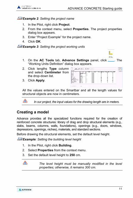
Example 2: Setting the project name
1. In the Pilot, right click Project. 2. From the context menu, select Properties. The project properties
dialog box appears. 3. Enter “Project Example” for the project name. 4. Click OK. Example 3: Setting the project working units
1. On the AC Tools tab, Advance Settings panel, click . The “Working Units Definition” dialog box appears.
2. Click lengths Type column and select Centimeter from the drop-down list.
3. Click Apply.
All the values entered on the Smartbar and all the length values for structural objects are now in centimeters.
In our project, the input values for the drawing length are in meters.
Creating a model Advance provides all the specialized functions required for the creation of reinforced concrete structures: library of drag and drop structural elements (e.g., slabs, beams, columns, walls, foundations), openings (e.g., doors, windows, depressions, openings, niches), materials, and standard sections. Before drawing the structural elements, set the default level height.
Example: Setting the building level height
1. In the Pilot, right click Building. 2. Select Properties from the context menu. 3. Set the default level height to 250 cm.
The level height must be manually modified in the level properties; otherwise, it remains 300 cm.
11

ADVANCE CONCRETE Starting guide
4. Right click Level 1. 5. Set the level height to 250 cm.
Creating walls Advance provides a tool for creating several wall types: • Straight walls: using two points • Continuous walls • Curved walls: using three circle points or two points and a center point. Different kinds of walls are created using the “Properties” dialog box.
Example: Creating straight walls
1. On the AC Model tab, Structure panel, click . 2. Press F8 to activate the Ortho mode. 3. Click the graphic area to define a starting point and input the
following values:
– Move the mouse cursor in the X-direction, enter 5 on the command line, and press <Enter>
– Move the mouse cursor in the Y-direction, enter 3 and press <Enter>
– Move the mouse cursor again in the Y-direction, enter 4 and press <Enter>
– Move the mouse cursor in the -X-direction, enter 5 and press <Enter>
– Move the mouse cursor in the -Y-direction, enter 7 and press <Enter>
4. Press Esc to end.
12

ADVANCE CONCRETE Starting guide
Using the UCS AutoUCS is an efficient and easy to use tool when working with relative coordinates in the creation and modification of structural elements. It can also be used as a measuring tool.
Example: Using the UCS to create a wall
1. On the AC Model tab, Structure panel, click . 2. On the Display and selection tool palette, click “Dynamic
wedging” . 3. Click the upper corner of the wall to place the
AutoUCS origin.
4. On the command line, enter the values 3,0 and press <Enter>. The
start point of the wall is selected.
5. Move the mouse cursor in the -Y-direction, enter 2 and press <Enter>.
6. Move the mouse cursor in the X-direction, enter 2 and press <Enter>.
13

ADVANCE CONCRETE Starting guide
Creating columns Using the Advance tools all types of columns are created: • Straight columns • Columns with slants according to a distance or an angle • Columns with a tapered section • Drop panel on the top of the columns
Example: Creating a straight column
1. On the AC Model tab, Structure panel, click . 2. On the Smartbar, enter R20x20 to draw a column with a square-
shaped section and 20 cm sides: 3. On the Smartbar, select the central snap point from the drop-down list.
4. Press <Enter>. 5. Position the first column at the bottom right corner. 6. Click to indicate the column orientation angle.
Draw as many columns as necessary using the same process.
7. Press Esc to finish.
Copy
To copy an element to a new position click “Copy” on the Modify panel of the Home tab.
14
ADVANCE CONCRETE Starting guide
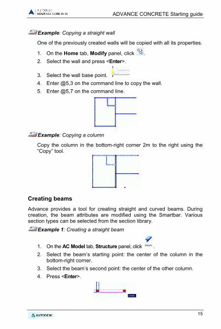
Example: Copying a straight wall
One of the previously created walls will be copied with all its properties.
1. On the Home tab, Modify panel, click . 2. Select the wall and press <Enter>.
3. Select the wall base point. 4. Enter @5,3 on the command line to copy the wall. 5. Enter @5,7 on the command line.
Example: Copying a column
Copy the column in the bottom-right corner 2m to the right using the “Copy” tool.
Creating beams Advance provides a tool for creating straight and curved beams. During creation, the beam attributes are modified using the Smartbar. Various section types can be selected from the section library.
Example 1: Creating a straight beam
1. On the AC Model tab, Structure panel, click . 2. Select the beam’s starting point: the center of the column in the
bottom-right corner. 3. Select the beam’s second point: the center of the other column. 4. Press <Enter>.
15

ADVANCE CONCRETE Starting guide
Example 2: Creating a curved beam
1. On the AC Model tab, Structure panel, select . 2. Click the center of the first column. 3. On the command line, type CE (Center) and press <Enter>. 4. Specify the center on the horizontal wall.
To select the curve center, press the CTRL key and right click. Select Perpendicular from the context menu.
The beam is drawn in the trigonometric direction from the start point to the end one.
5. Click the center of the second column. 6. Press <Enter>.
16

ADVANCE CONCRETE Starting guide
Creating slabs Advance provides a tool that creates a slab in the current level. Slabs are created: • By automatic detection • Point by point During the creation, the slab attributes are modified using the Smartbar. New slab points can be added using CAD tools.
Example: Creating slabs by automatic detection
1. On the AC Model tab, Structure panel, click . 2. On the command line, enter D (Detection) and press <Enter>. 3. Click the four areas (as shown in the figure) to create the slabs. 4. Press Esc to end.
Creating openings Advance provides commands for creating all kinds of openings (e.g., doors, windows, depressions, floor openings, and niches) and all kinds of holes shapes (e.g., rectangular, circular, and polygonal). The Opening object depends entirely on the Wall object. Thus, when moving a wall, the opening is moved with it. If a wall is deleted, the opening linked to the wall is also deleted.
Example: Creating a window
1. On the AC Model tab, Openings panel, click . 2. Click the bottom wall. 3. Place the window in the middle of the wall using the snap modes to
objects.
17

ADVANCE CONCRETE Starting guide
Opening libraries The doors and windows used in an Advance project can be modified or inserted from a library. The library must first be imported into the model. The libraries can contain several doors and windows that are shared by different elements of the model. Using and modifying the common library element decreases the memory space and improves Advance performance.
Example: Modifying a window
1. On the AC Tools tab, Advance settings panel, click . The “Doors and windows library” dialog box appears.
2. Click the Windows tab. 3. Select the window type to modify. 4. Click Properties. The properties of the selected window are displayed
on another panel of the window. The properties are read-only.
5. Click Modify . 6. In the table, modify the window opening
size. 7. Click OK.
Example: Creating a door
1. On the AC Model tab, Openings panel, click . 2. Click the wall. 3. On the Smartbar, select the door style (e.g., LD 90x218 C7 J1). 4. Click the middle of the wall to place the door. 5. Next, click inside the building to define the door opening direction.
18

ADVANCE CONCRETE Starting guide
Example: Creating a circular wall opening
1. On the AC Model tab, Openings panel, click . 2. Click the wall. 3. Click the middle of the wall to place the opening.
The opening is created. The properties can be modified.
On the Smartbar, click . – Click the arrow and select the circular
opening . – Enter the diameter: 200 cm – Enter 25 cm for the sill. – Close the dialog box.
Automatically creating a new level Advance provides commands for copying an entire level as well as all its elements, which is useful when building levels are similar.
Copy level at top
Copy level below Optionally, the created plan view can also be copied to avoid recreating all the visual elements for the level.
Example: Copying a level at top
1. In the Pilot, activate the first level.
2. On the AC Model tab, Management panel, click . 3. Type N (No) and press <Enter> to confirm.
The new level appears in the Pilot.
Double click Building in the Pilot. The two levels of the 3D building are displayed in 3D.
19

ADVANCE CONCRETE Starting guide
Shade/Cancel Shade
For a more realistic presentation of the model, use a shaded visual style. From the menus on the top-left corner of the drawing area select Realistic. To change the view angle, use the options from the menus on the top-left corner of the application window.
To cancel the shading, return to the 2D Wireframe visual style.
20

ADVANCE CONCRETE Starting guide
Creating foundations Advance provides commands for creating isolated and continuous footings, beddings for isolated and continuous footings and piles, and a command for automatic foundation creation under the elements of the building's lowest level. The determination of the footing size depends only on the supporting geometry element.
Example: Automatically creating foundations
1. On the AC Model tab, Foundation panel, click . 2. Select the Automatic determinations of footings option. 3. Click OK. The foundations are automatically placed under the first level of the
building.
Plan view
To display the plan view, select the corresponding option from the menus on the top-left corner of the application window.
21
ADVANCE CONCRETE Starting guide
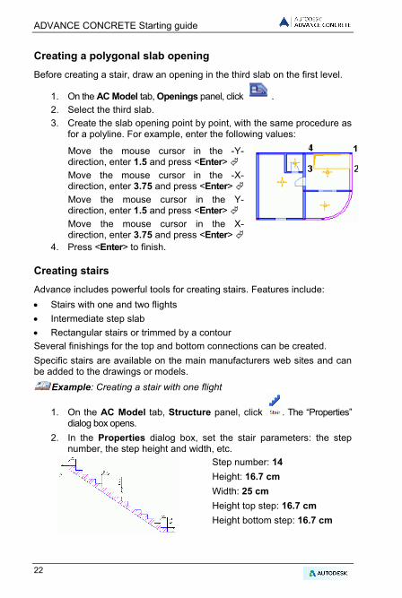
Creating a polygonal slab opening Before creating a stair, draw an opening in the third slab on the first level.
1. On the AC Model tab, Openings panel, click . 2. Select the third slab. 3. Create the slab opening point by point, with the same procedure as
for a polyline. For example, enter the following values:
Move the mouse cursor in the -Y-direction, enter 1.5 and press <Enter> Move the mouse cursor in the -X- direction, enter 3.75 and press <Enter> Move the mouse cursor in the Y-direction, enter 1.5 and press <Enter> Move the mouse cursor in the X-direction, enter 3.75 and press <Enter>
4. Press <Enter> to finish.
Creating stairs Advance includes powerful tools for creating stairs. Features include: • Stairs with one and two flights • Intermediate step slab • Rectangular stairs or trimmed by a contour Several finishings for the top and bottom connections can be created. Specific stairs are available on the main manufacturers web sites and can be added to the drawings or models.
Example: Creating a stair with one flight
1. On the AC Model tab, Structure panel, click . The “Properties” dialog box opens.
2. In the Properties dialog box, set the stair parameters: the step number, the step height and width, etc.
Step number: 14 Height: 16.7 cm Width: 25 cm Height top step: 16.7 cm Height bottom step: 16.7 cm
22

ADVANCE CONCRETE Starting guide
3. On the Upper anchor tab, use the Next and Previous buttons to select the desired top anchor stair.
4. On the Lower anchor tab, use the Next and Previous buttons to
select the desired bottom anchor stair.
5. Click OK. 6. Place the stairs by clicking the two points defining the width.
7. Press <Enter> to finish.
The stair upper level must be defined relative to the lower level.
8. Select the stair and double click it to access the stair properties. 9. On the Definition tab, select In relation to lower level in the
“Upper level” drop-down list. 10. Enter 0 cm in the Value field.
23

ADVANCE CONCRETE Starting guide
DRAWING CREATION
Advance provides a large selection of view creation tools. Once the model is complete, the creation of the construction drawing can begin. Sections, elevations, isometric views, total or partial cuts can be automatically created.
The tools for creating drawings and views are grouped on the Drawing creation panel of the AC Model tab.
Before starting a project it is necessary to carefully plan how it will be handled. Advance Concrete provides two behaviors: • The three dimensional model and the created drawings are stored in a
single .dwg file. • The three dimensional model is stored in a drawing (in DWG format).
All the drawings and layouts created from the model are saved in separate .dwg files.
Note: The example used in this guide is handled using the "external drawings" behavior (default setting).
Example 1: Creating a cut
1. On the AC Model tab, Drawing creation panel, click . 2. Draw the cutting plane. To define
it, draw a vertical line across the building and press <Enter>.
3. Move the mouse to define the cut depth. Include the entire left part of the building.
Next, calculate the cut:
4. In the Pilot, click to enter the Drawings mode. Section A-A appears. A red mark indicates that the view is not updated.
Double click Section A-A to calculate the section.
24

ADVANCE CONCRETE Starting guide
Example 2: Creating a plan view
For every level, a corresponding plan view can be created. This association is automatically managed by Advance. The plan view is different from the level as it is just a model representation. All the necessary annotations, dimensions and other visual elements can be added. New entities cannot be created but the existing entities can be modified. Every modification made in the plan view affects the model.
1. In the Pilot, click Model to enter the Model mode. 2. Double click Building to activate it.
3. On the AC Model tab, Drawing creation panel, click . 4. In the “Select level” dialog box, click the first level. 5. Click OK. The plan view is created.
25
ADVANCE CONCRETE Starting guide
Dimensions Advance provides tools for creating all dimensions types. • Coordinate dimensions – displays the X and Y coordinates of the
selected point. • Level dimensions – places a symbol and an altitude on a number of
points placed on a straight line. One of the points is considered as the altitudes origin and the associated altitude to this point can be changed. The other altitudes are calculated from the origin.
• Arc dimensions – dimensions the circle arc length or a curved object. • Intersection dimension – takes into account the intersections with
standard graphic objects, model objects, as well as reinforcement elements and model contours.
• Associative dimension – automatically displays a certain number of preliminary defined dimensions for a given object. These dimensions apply to the object and its children (e.g., openings) and they can be entirely defined according the selected elements.
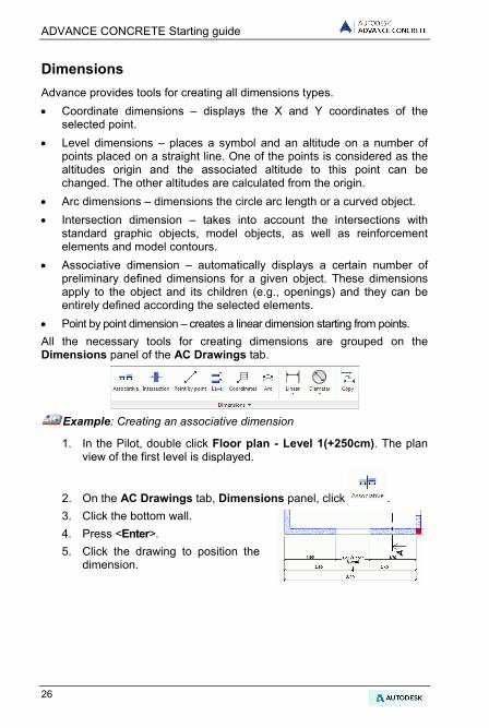
• Point by point dimension – creates a linear dimension starting from points. All the necessary tools for creating dimensions are grouped on the Dimensions panel of the AC Drawings tab.
Example: Creating an associative dimension
1. In the Pilot, double click Floor plan - Level 1(+250cm). The plan view of the first level is displayed.
2. On the AC Drawings tab, Dimensions panel, click . 3. Click the bottom wall. 4. Press <Enter>. 5. Click the drawing to position the
dimension.
26

ADVANCE CONCRETE Starting guide
Layouts Advance automatically creates layouts based on drawings. Title blocks and frames can be inserted in the layout.
Note: Layouts are defined in the Documents mode.
Example 1: Creating a layout with title block
A layout is created using the views created in the previous examples. The views are placed on the layout plan by dragging them from the Pilot.
1. In the Pilot, click Documents to enter the Documents mode. 2. In the Pilot, right click the Layout folder and select Create layout
from the context menu. The layout properties dialog box appears. 3. Click Modify to add a title block or to modify the formatting.
4. In the properties dialog box, check Title blocks.
5. Click . 6. In the “Title block” dialog box, click Add. 7. Browse and select a title block from the Advance folder tree (e.g.,
[Windows drive]:\Users\[UserName]\AppData\Roaming\Autodesk\AdvanceConcrete\2015\Support\Sample\Document\TitleBlock A4.a.dwg).
8. Click OK. 9. In the properties dialog box, click OK.
27
ADVANCE CONCRETE Starting guide
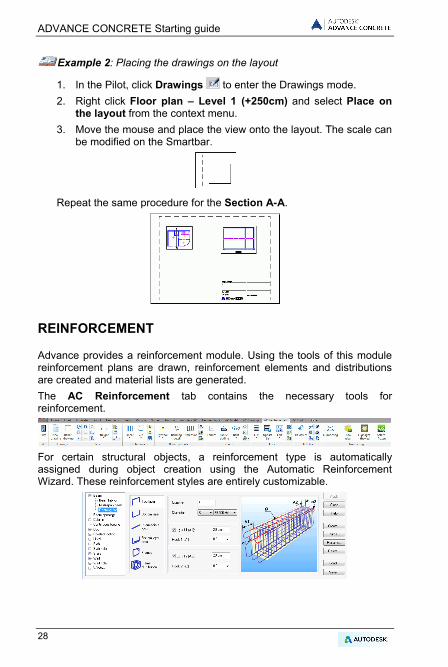
Example 2: Placing the drawings on the layout
1. In the Pilot, click Drawings to enter the Drawings mode. 2. Right click Floor plan – Level 1 (+250cm) and select Place on
the layout from the context menu. 3. Move the mouse and place the view onto the layout. The scale can
be modified on the Smartbar.
Repeat the same procedure for the Section A-A.
REINFORCEMENT
Advance provides a reinforcement module. Using the tools of this module reinforcement plans are drawn, reinforcement elements and distributions are created and material lists are generated. The AC Reinforcement tab contains the necessary tools for reinforcement.
For certain structural objects, a reinforcement type is automatically assigned during object creation using the Automatic Reinforcement Wizard. These reinforcement styles are entirely customizable.
28

ADVANCE CONCRETE Starting guide
Reinforcement drawing The basic plan for creating the reinforcement drawing is automatically created from a selected structural element. According to the selected view arrangement type, Advance creates the cuts and elevations.
Example: Creating the reinforcement drawing for a wall with a window opening
Activate the second level of the building.
1. On the AC Model tab, Drawing creation panel, click .
Note: This command is accessible only in the Model mode.
2. Select the bottom wall and press <Enter> to confirm. The first dialog box of the reinforcement view creation wizard appears.
3. On the right side of the dialog box select the arrangement of the views calculated by Advance: the number of views and the type of views. A graphic representation is displayed on the right side.
4. Click Next. 5. Click the viewport to modify. The picture changes accordingly. Next, the
parameters can be modified on the right side of the window. In the following steps, various parameters modify the edge styles
for the visible and hidden objects, reinforcement representation styles, display of symbols, axes and symbol scale, and title parameters. Keep the default parameters and click Next.
6. By clicking Finish, the views are automatically created and the reinforcement drawing appears in the Pilot in Drawings mode.
Next the reinforcement can be drawn.
Creating the reinforcement Next, the necessary bars are added on the drawing.
Example 1: Creating a rectangular bar on the window lintel cut
1. On the AC Reinforcement tab, Bars panel, click . 2. Place the frame by clicking two points of the lintel diagonal. 3. Click a third point to position the hook of the rectangular frame.
The frame is created.
29

ADVANCE CONCRETE Starting guide
Example 2: Creating a U bar
1. On the AC Reinforcement tab, Bars panel, click . 2. Place a U bar by clicking two points of the U base. 3. Input the U direction in the wall and the desired U length value. The U bar is created.
Similar, place a U bar on the window top view
Next, distributions are created around the window opening based on the three previously created bars. Example3: Creating a linear distribution
A distribution is created based on the rectangular frame. 1. On the AC Reinforcement tab, Distributions panel, select
from the flyout. 2. Click the frame.
The Sideview tool automatically appears as two arrows. This tool sets the distribution bar direction.
3. Select the horizontal arrow to place this side of the rectangular frame on the wall elevation.
Zoom in on the window lintel on the wall elevation 4. Click the lower left corner of the lintel, and then the lower right corner.
5. Next, click the lintel to specify the distribution bar direction.
30

ADVANCE CONCRETE Starting guide
6. Using the gray rectangular frame, set the bar position in the distribution.
Similarly, place a U bar distribution on the window top view. Create a distribution with the U bar on the window sill.
Example 4: Creating a straight bar
Zoom in on the window lintel on the wall elevation. First, the lower bar of the window lintel will be defined. Zoom in on the window lintel on the wall elevation.
1. On the AC Reinforcement tab, Bars panel, click . 2. On the Smartbar, select anchor for bar extremities 1 and 2. 3. On the command line, type li (line) and press <Enter>.
4. Click the lower lintel edge. 5. Click inside the lintel to place the lower bar. The bar is defined.
31

ADVANCE CONCRETE Starting guide
Repeat the process to place a bar in the window sill and another one on the side of the window.
Example 5: Creating a free distribution
Next, a distribution is created based on the straight bars. Zoom in on the elevation on the lower bar of the window lintel. 1. On the AC Reinforcement tab, Distributions panel, select
from the flyout. 2. Click the bar on the lower lintel side. A point bar is hooked on the
cross center of the mouse cursor. 3. Create a distribution of two point bars around the rectangular frame
from the lintel section.
Note: To facilitate the placement of these two point bars, activate the snap point "center" on the snap object.
Click the horizontal bar of the sill on the elevation. Repeat the process to create the distribution inside the U bar of the window sill and a distribution inside the U bar on the left side of the window (top view). Next, using symmetry, place the bars on the other side of the window. Zoom in so that the elevation and the top view are visible on the screen.
32
ADVANCE CONCRETE Starting guide
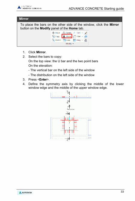
Mirror
To place the bars on the other side of the window, click the Mirror button on the Modify panel of the Home tab.
1. Click Mirror. 2. Select the bars to copy: On the top view: the U bar and the two point bars On the elevation: - The vertical bar on the left side of the window - The distribution on the left side of the window 3. Press <Enter>. 4. Define the symmetry axis by clicking the middle of the lower
window edge and the middle of the upper window edge.
33
ADVANCE CONCRETE Starting guide
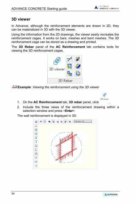
3D viewer In Advance, although the reinforcement elements are drawn in 2D, they can be materialized in 3D with the 3D viewer. Using the information from the 2D drawings, the viewer easily recreates the reinforcement cages. It works on bars, meshes and bent meshes. The 3D reinforcement cage can be stored as a drawing and printed. The 3D Rebar panel of the AC Reinforcement tab contains tools for viewing the 3D reinforcement cages.
Example: Viewing the reinforcement using the 3D viewer
1. On the AC Reinforcement tab, 3D rebar panel, click . 2. Include the three views of the reinforcement drawing within a
selection window and press <Enter>. The wall reinforcement is displayed in 3D.
34

ADVANCE CONCRETE Starting guide
Placing the reinforcement symbols Symbols are combinations of annotations and graphic elements. They contain a certain number of object attributes. They are updated as the objects are modified. Deleting the objects deletes the corresponding symbols. The symbols are placed one by one on the reinforcement elements: bars, simple or bent meshes, and bars and bent meshes distributions.
Example: Placing a bar symbol
This example shows the placing of a bar reference mark on the wall cut. Zoom in on the lintel section.
1. On the AC Reinforcement tab, Rebar symbols panel, click . 2. Click the rectangular frame and place the reference mark nearby. Repeat the process to place a reference mark on the two point bars.
Repeat the process to place the reference marks for the sill reinforcement.
Distribution dimensions Advance provides a command for creating dimensions on the linear or variable distributions.
Example: Dimensioning a linear distribution
Zoom in on the window lintel elevation.
1. On the AC Reinforcement tab, Rebar symbols panel, click . 2. Click the rectangular frame distribution. 3. Place the dimension line. 4. Click the position for the reference mark. Repeat the process to place the dimensions for the four distributions of the window.
35

ADVANCE CONCRETE Starting guide
Lists Advance provides a command for creating lists on layouts. Lists are created based on templates and are associated to structural element types (i.e., beams, columns, etc.) and to reinforcement element types (i.e., bars, meshes, etc.). Different list and schedule templates are available according to the international markets. Custom list templates can also be created using the List generator. The lists are automatically updated.
Example: Creating a bar list
1. On the AC Reinforcement tab, List panel, click .
2. From the dialog box, select All bars . 3. Include within a selection window the bars to list. 4. Press <Enter>.
5. The list is hooked to the mouse cursor. 6. On the Smartbar, select a template and a scale of 0.5. 7. Place the list on the reinforcement drawing.
This small exercise was a very simple introduction to Advance Concrete. With time, your familiarity, speed, and understanding of the power and versatility of Advance Concrete will improve as you use the software on real projects.
36


Copyright © 2015 Autodesk, Inc.