Embed Size (px)
Citation preview
INVT INDUSTRIAL TECHNOLOGY (SHANGHAI) CO., LTD.
AC Servo System Catalog
201312(V1.0)
Service line:+86-21-34637660 Web:www.invt-tech.com
Committed to Premium Quality
Building 1, No.188 Xinjun Ring Rd., Pujiang Hi-Tech Park.,Shanghai,201114,China
01 02
Founded in 2005, INVT INDUSTRIAL TECHNOLOGY (SHANGHAI )CO.,LTD. (formerly Shanghai KINWAY Technologies Inc.), is
a Sino-foreign joint venture controlled by INVT (Stock Code: 002334). Incorporated by several PhDs of outstanding achievements
in automatic control returning from the United States, the Company has successfully introduced the ten-plus years’ experience of
renowned overseas large enterprises in technological development and management to China, and developed into an enterprise
with scientific and technological innovation integrating research, development, production, sales and services; it has established
two subsidiaries, i.e. SUZHOU KINWAY and NINGBO JUNWEI. Since its foundation, the Company has been honored as a
Technology Pionerring Enterprise in Zhangjiang Hi-tech Park, Shanghai Hi-tech Enterprise, Shanghai Innovative Enterprise and a
Corporate Research and Development Institute in Pudong New Area.
Relying on its internationally advanced core technologies for permanent magnet simultaneous motor, power electronics, digital
control, sensor, network, field bus, ect., INVT has developed a series of high-end servo systems and computer-controlled systems
specially for equipment, with INVT and KINWAY (two brands of the Company) products applied widely to plastic machinery, textile
machines, oil fields, machine tools, industrial robots, packing machines, electronic manufacturing and photovoltaic field.
The Company has been dedicated to using its leading servo drivers and automation technology to promote the equipment
manufacturing level and creating more value for the customers; it aspires to be a world-leading industrial automation product and
service provider that is respected by the people and trusted by the customers.
DB100 Series AC Servo System 03Application fields 04Servo Driver Product Description 05Servo Motor Product Description 07Servo Motor Product Description 08Servo driver & External device cable 11Standard Wiring Diagram 12Servo driver plug signal arrangement diagram 15
DA100 Series AC Servo System 16 System Composition 17Servo Driver’s Interface Drawing 18Product Advantages 18Servo Driver Type Description 19Technical Parameters of Servo Driver 20Mechanical Dimensions of Servo Driver 22Standard Wiring Diagram 23Servo Motor Type Description 2560/80-Flange Servo Motor 26130-Flange Servo Motor 27180-Flange Servo Motor 28Cable Type Description 29Servo System Order Guide 30
MH500 Servo-Hydraulic System For Injection Molding Machines 31Servo-Hydraulic System 32Servo-Hydraulic System for injection molding machine 33Selection 34System Specification 35MH500 Series Servo Driver Specifications 36MH500 Series Servo Driver Dimension 37Mm Series Servo Motor Specifications 38Mm Series Servo Motor Dimension 39System interconnect diagram 40Successful Cases 41
Sales & Service Network 42
CONTENTSCompany Profile
03 04
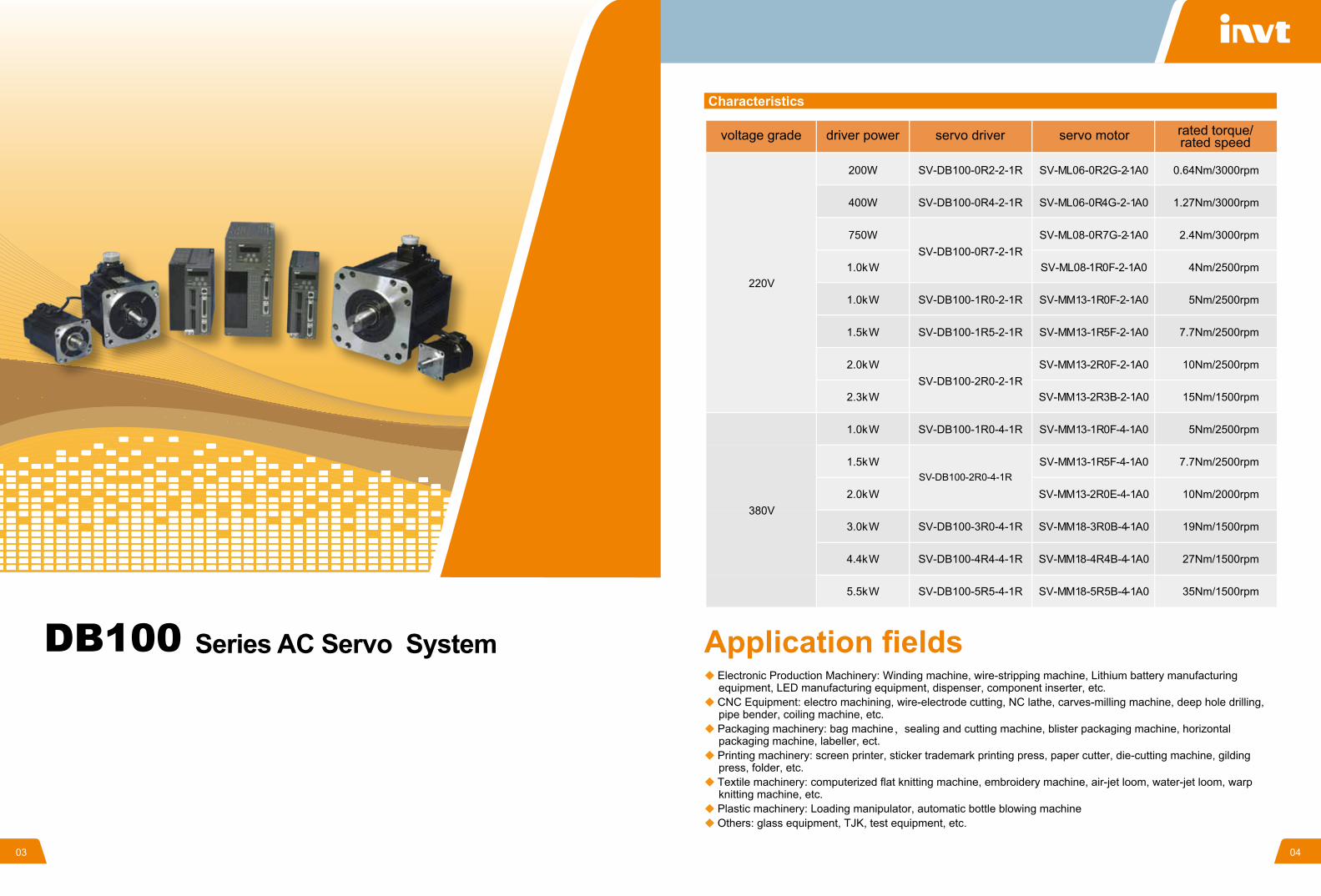
Electronic Production Machinery: Winding machine, wire-stripping machine, Lithium battery manufacturing equipment, LED manufacturing equipment, dispenser, component inserter, etc.
CNC Equipment: electro machining, wire-electrode cutting, NC lathe, carves-milling machine, deep hole drilling, pipe bender, coiling machine, etc.
Packaging machinery: bag machine,sealing and cutting machine, blister packaging machine, horizontal packaging machine, labeller, ect.
Printing machinery: screen printer, sticker trademark printing press, paper cutter, die-cutting machine, gilding press, folder, etc.
Textile machinery: computerized flat knitting machine, embroidery machine, air-jet loom, water-jet loom, warp knitting machine, etc.
Plastic machinery: Loading manipulator, automatic bottle blowing machineOthers: glass equipment, TJK, test equipment, etc.
220V
200W
400W
750W
1.0kW
1.0kW
1.5kW
2.0kW
2.3kW
1.0kW
1.5kW
2.0kW
3.0kW
4.4kW
5.5kW
0.64Nm/3000rpm
1.27Nm/3000rpm
2.4Nm/3000rpm
4Nm/2500rpm
5Nm/2500rpm
7.7Nm/2500rpm
10Nm/2500rpm
15Nm/1500rpm
5Nm/2500rpm
7.7Nm/2500rpm
10Nm/2000rpm
19Nm/1500rpm
27Nm/1500rpm
35Nm/1500rpm
SV-ML06-0R2G-2-1A0
SV-ML06-0R4G-2-1A0
SV-ML08-0R7G-2-1A0
SV-ML08-1R0F-2-1A0
SV-MM13-1R0F-2-1A0
SV-MM13-1R5F-2-1A0
SV-MM13-2R0F-2-1A0
SV-MM13-2R3B-2-1A0
SV-MM13-1R0F-4-1A0
SV-MM13-1R5F-4-1A0
SV-MM13-2R0E-4-1A0
SV-MM18-3R0B-4-1A0
SV-MM18-4R4B-4-1A0
SV-MM18-5R5B-4-1A0
SV-DB100-0R2-2-1R
SV-DB100-0R4-2-1R
SV-DB100-0R7-2-1R
SV-DB100-1R0-2-1R
SV-DB100-1R5-2-1R
SV-DB100-2R0-2-1R
SV-DB100-1R0-4-1R
SV-DB100-3R0-4-1R
SV-DB100-4R4-4-1R
SV-DB100-5R5-4-1R
380V
Characteristics
voltage grade driver power servo driver servo motor rated torque/rated speed
Application fieldsSeries AC Servo System
SV-DB100-2R0-4-1R
05 06
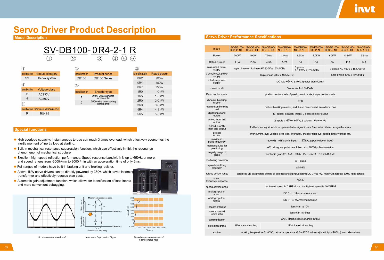
High overload capacity: Instantaneous torque can reach 3 times overload, which effectively overcomes the inertia moment of inertia load at starting.
Built-in mechanical resonance suppression function, which can effectively inhibit the resonance phenomenon of mechanical structure.
Excellent high-speed reflection performance: Speed response bandwidth is up to 650Hz or more, and speed ranges from -3000r/min to 3000r/min with an acceleration time of only 6ms.
Full ranges of models have built-in braking unit and braking resistor. Above 1KW servo drivers can be directly powered by 380v, which saves incoming
transformer and effectively reduces plan costs. Automatic gain adjustment function, which allows for identification of load inertia
and more convenient debugging.
Servo Driver Product Description
Identification Identification Identification
IdentificationIdentification
Identification
Product categoryServo system
Product series Series
Rated power
Voltage classEncoder type
Communication mode
2500-wire standardincremental
2500-wire wire-savingincremental
Special functions
0.1r/min current waveformR esonance Suppression Figure Speed response waveform of5 times inertia ratio
Res
pons
e of
m
echa
nica
l sys
tem
Sup
pres
sion
ampl
itude
Mechanical resonance point
Suppression frequency
Frequency
spee
d
Time
Frequency
Model Description
AC230VAC400V
3 phase AC 230V +15%/50Hz
Servo Driver Performance Specifications
07 08
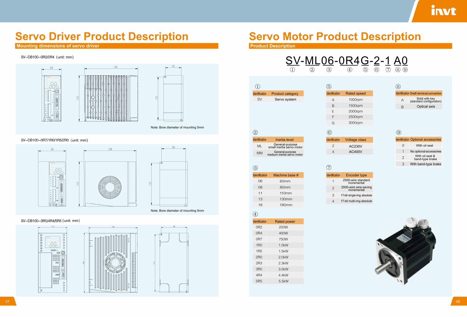
Servo Driver Product DescriptionMounting dimensions of servo driver
unit: mm
Note: Bore diameter of mounting 5mm
Note: Bore diameter of mounting 5mm
unit: mm
unit: mm
Servo Motor Product DescriptionProduct Description
Product categoryServo system
IdentificationIdentification
Identification Identification
Identification
Identification
Identification
Rated speed Shaft terminal connectionSolid with key
(standard configuration)
Optical axis
Inertia levelGeneral-purpose
small inertia servo motorGeneral-purpose
medium inertia servo motor
Machine base #
Rated power
Voltage class Optional accessories
With oil seal
No optional accessoriesWith oil seal &
band-type brakeWith band-type brake
17-bit multi-ring absolute
2500-wire standardincremental
2500-wire wire-savingincremental
17-bit single ring absolute
Identification Encoder type
Identification
AC230VAC400V
09 10
Motor typeFlange facedimension Shaft end dimension
Weight
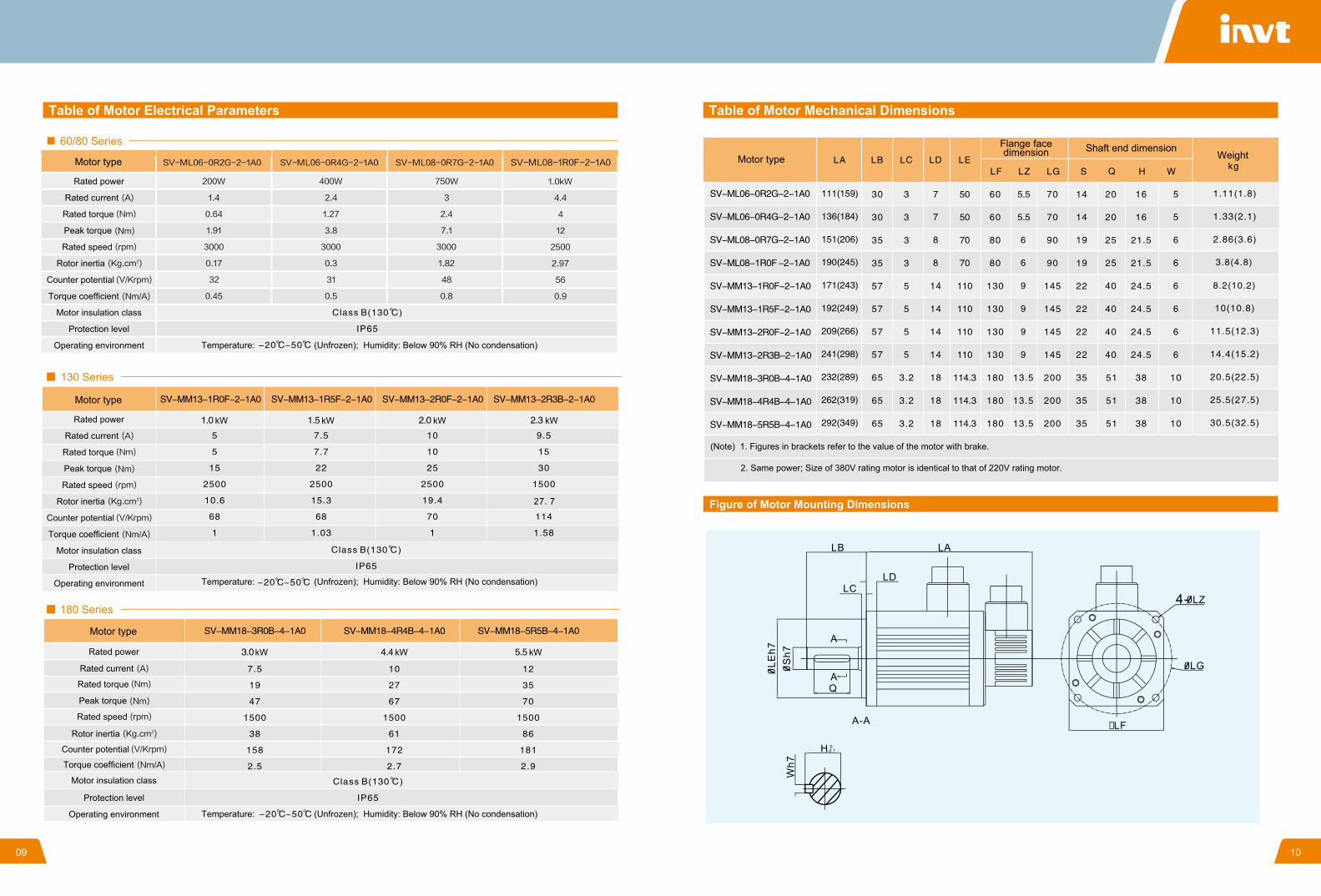
(Note) 1. Figures in brackets refer to the value of the motor with brake.
2. Same power; Size of 380V rating motor is identical to that of 220V rating motor.
Table of Motor Mechanical Dimensions
Figure of Motor Mounting Dimensions
Motor type
60/80 Series
130 Series
180 Series
Operating environment
Protection level
Motor insulation class
Torque coefficient
Counter potential
Rated power
Rated current
Rated torque
Peak torque
Rated speed
Rotor inertia
Motor type
Operating environment
Protection level
Motor insulation class
Torque coefficient
Counter potential
Rated power
Rated current
Rated torque
Peak torque
Rated speed
Rotor inertia
Motor type
Operating environment
Protection level
Motor insulation class
Torque coefficient
Counter potential
Rated power
Rated current
Rated torque
Peak torque
Rated speed
Rotor inertia
Temperature: (Unfrozen); Humidity: Below 90% RH (No condensation)
Temperature: (Unfrozen); Humidity: Below 90% RH (No condensation)
Temperature: (Unfrozen); Humidity: Below 90% RH (No condensation)
Table of Motor Electrical Parameters
11 12
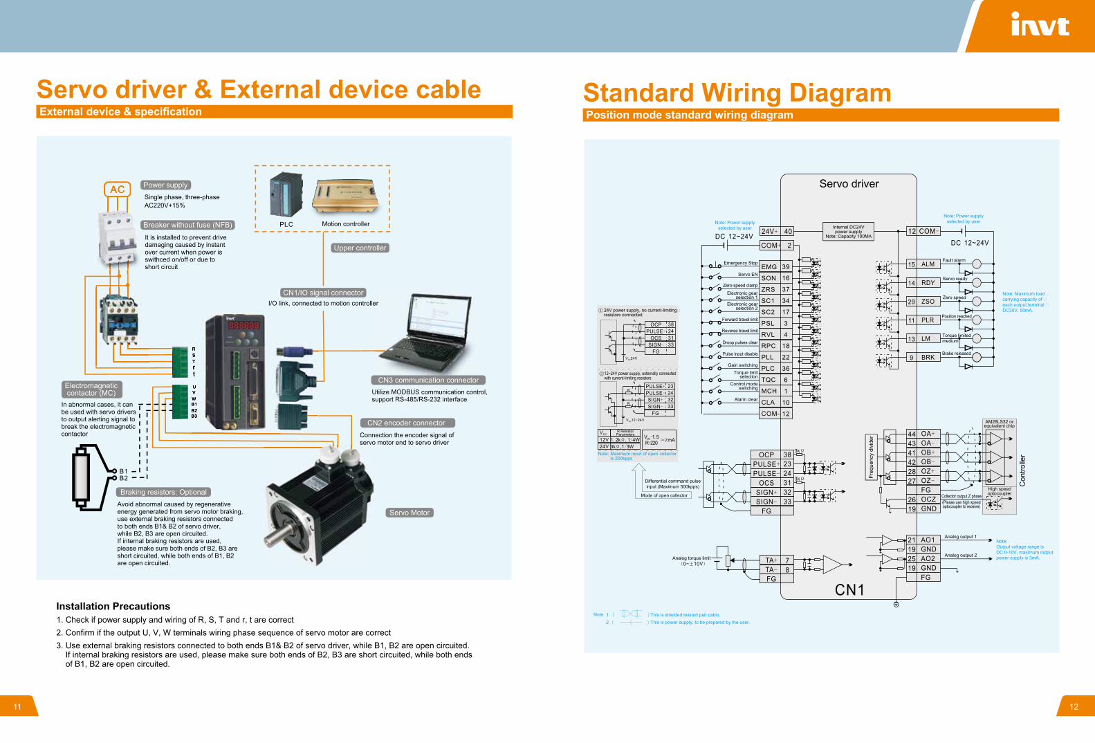
Servo driver & External device cableExternal device & specification
Power supply
Electromagneticcontactor (MC)
Upper controller
Servo Motor
CN3 communication connector
CN2 encoder connector
Braking resistors: Optional
CN1/IO signal connector
Breaker without fuse (NFB)
Single phase, three-phase AC220V+15%
Motion controller
I/O link, connected to motion controller
It is installed to prevent drive damaging caused by instant over current when power is swithced on/off or due to short circuit
Utilize MODBUS communication control, support RS-485/RS-232 interface
Connection the encoder signal of servo motor end to servo driver
In abnormal cases, it can be used with servo drivers to output alerting signal to break the electromagnetic contactor
Installation Precautions1. Check if power supply and wiring of R, S, T and r, t are correct2. Confirm if the output U, V, W terminals wiring phase sequence of servo motor are correct3. Use external braking resistors connected to both ends B1& B2 of servo driver, while B1, B2 are open circuited. If internal braking resistors are used, please make sure both ends of B2, B3 are short circuited, while both ends of B1, B2 are open circuited.
Avoid abnormal caused by regenerative energy generated from servo motor braking, use external braking resistors connected to both ends B1& B2 of servo driver, while B2, B3 are open circuited. If internal braking resistors are used, please make sure both ends of B2, B3 are short circuited, while both ends of B1, B2 are open circuited.
High speedoptocoupler
Analog output 1
Analog output 2
Standard Wiring DiagramPosition mode standard wiring diagram
Servo driver
Emergency Stop
24V power supply, no current-limiting�resistors connected
R ResistorParameters
12~24V power supply, externally connected with current-limiting resistors
Servo EN
Zero-speed clamp
Electronic gearselection 1
Electronic gearselection 2
Forward travel limit
Reverse travel limit
Droop pulses clear
Pulse input disable
Gain switchingTorque limit
selectionControl mode
switching
Alarm clear
Brake released
Fault alarm
Note: Maximum load �carrying capacity of �each output terminal �DC30V, 50mA.
Note: Power supplyselected by userNote: Power supply
selected by user
Servo ready
Zero speed
Position reached
Torque limitedmedium
Internal DC24Vpower supply
Note: Capacity 100MA
AM26LS32 or�equivalent chip
Collector output Z phase(Please use high speedoptocoupler to receive)
Freq
uenc
y di
vide
r
Con
trolle
r
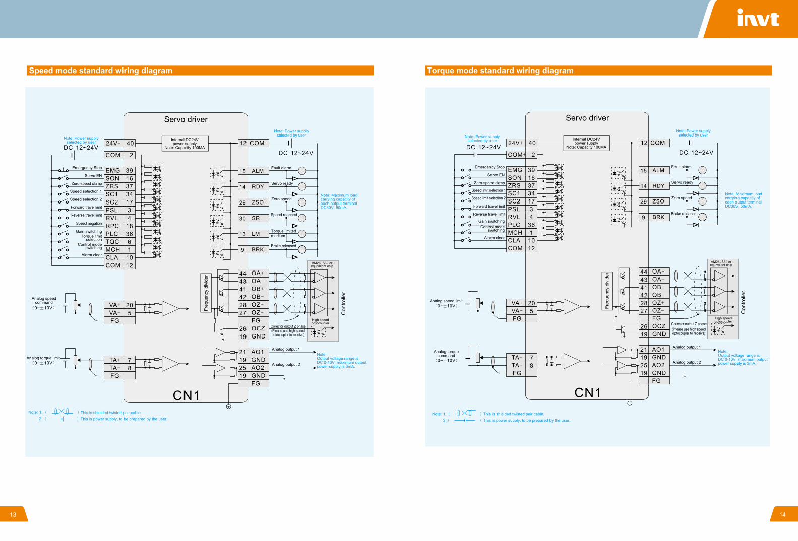
Note:Output voltage range is DC 0-10V, maximum output power supply is 3mA.
Note: Maximum input of open collector is 200kpps
Differential command pulseinput (Maximum 500kpps)
Mode of open collector
Analog torque limit
Note: This is shielded twisted pair cable.This is power supply, to be prepared by the user.
1.2.
01 1413
Speed mode standard wiring diagram
High speedoptocoupler
Freq
uenc
y di
vide
r
Collector output Z phase
Analog output 1
Analog output 2
(Please use high speedoptocoupler to receive)
Internal DC24Vpower supply
Note: Capacity 100MA
Servo driver
AM26LS32 or�equivalent chip
Con
trolle
r
Note:Output voltage range is DC 0-10V, maximum output power supply is 3mA.
Note: Maximum load carrying capacity of �each output terminal �DC30V, 50mA.
Note: Power supplyselected by user
Note: Power supplyselected by user
Note: This is shielded twisted pair cable.This is power supply, to be prepared by the user.
1.2.
Analog speedcommand
Analog torque limit
Brake released
Fault alarm
Servo ready
Zero speed
Speed reached
Torque limitedmedium
Emergency Stop
Servo EN
Zero-speed clamp
Speed selection 2
Speed selection 1
Forward travel limit
Reverse travel limit
Speed negation
Gain switchingTorque limit
selectionControl mode
switching
Alarm clear
Servo driver
Torque mode standard wiring diagram
Con
trolle
r
Freq
uenc
y di
vide
r
Collector output Z phase(Please use high speedoptocoupler to receive)
Analog output 1
Analog output 2
Note: Power supplyselected by user
Note: This is shielded twisted pair cable.This is power supply, to be prepared by the user.
1.2.
Internal DC24Vpower supply
Note: Capacity 100MA
Emergency Stop
Speed limit selection 1
Speed limit selection 2
Servo EN
Zero-speed clamp
AM26LS32 orequivalent chip
High speedoptocoupler
Note:Output voltage range is DC 0-10V, maximum output power supply is 3mA.
Note: Maximum load carrying capacity of each output terminal DC30V, 50mA.
Note: Power supplyselected by user
Analog speed limit
Analog torquecommand
Brake released
Fault alarm
Servo ready
Zero speed
Gain switchingControl mode
switching
Alarm clear
Forward travel limit
Reverse travel limit
15 16
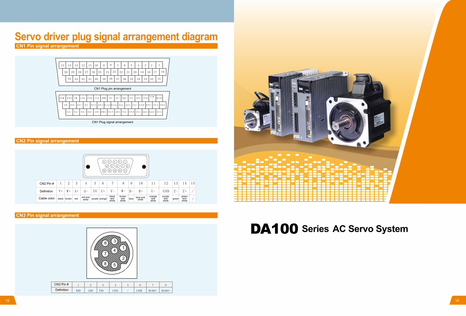
Servo driver plug signal arrangement diagramCN1 Pin signal arrangement
CN2 Pin signal arrangement
CN3 Pin signal arrangement
CN1 Plug pin arrangement
CN1 Plug signal arrangement
CN2 Pin #
Definition
black brown red red andwhite
blackand
whiteblue and
whiteorange
andwhite
brownand
white
purpleand
white
greenand
whitepurple orange blue greenCable color
CN3 Pin #
Definition
DA100 Series AC Servo System
17
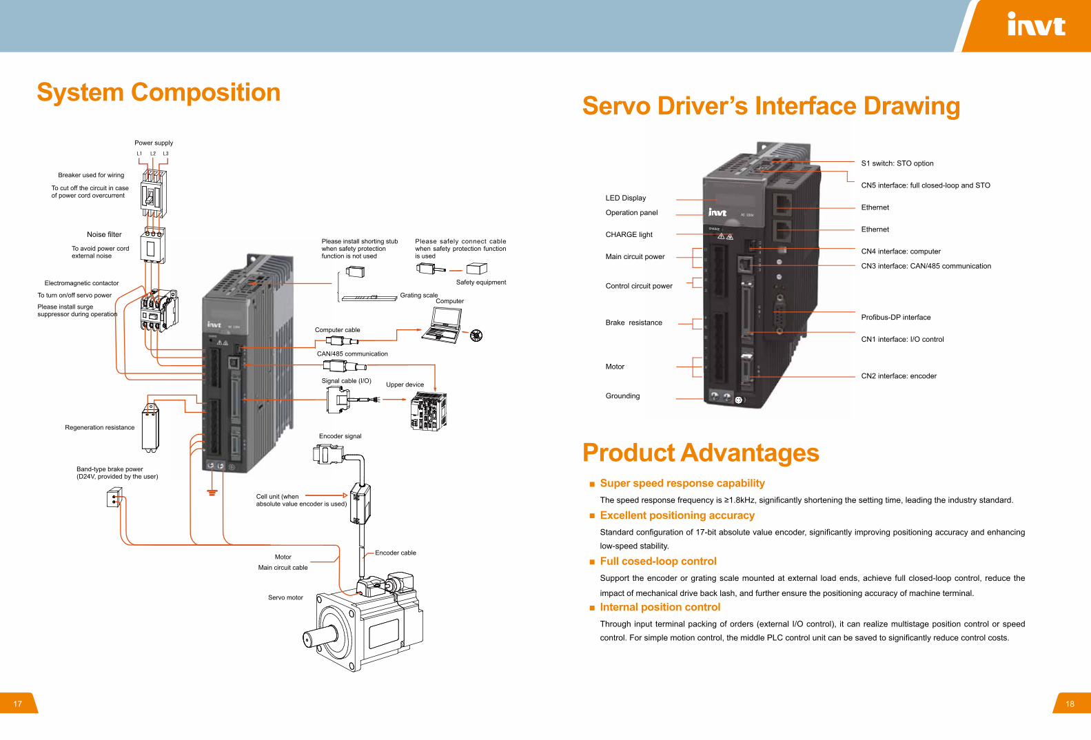
System CompositionPower supply
Breaker used for wiring
To avoid power cord external noise
To cut off the circuit in case of power cord overcurrent
Noise filter
Electromagnetic contactor
To turn on/off servo power
Please install surge suppressor during operation
Please install shorting stub when safety protection function is not used
Please safely connect cable when safety protection function is used
Grating scale
Safety equipment
Computer
Computer cable
CAN/485 communication
Signal cable (I/O) Upper device
Regeneration resistance Encoder signal
Band-type brake power (D24V, provided by the user)
Cell unit (when absolute value encoder is used)
Motor Main circuit cable
Encoder cable
Servo motor
Product AdvantagesSuper speed response capabilityThe speed response frequency is ≥1.8kHz, significantly shortening the setting time, leading the industry standard.
Excellent positioning accuracyStandard configuration of 17-bit absolute value encoder, significantly improving positioning accuracy and enhancing
low-speed stability.
Full cosed-loop controlSupport the encoder or grating scale mounted at external load ends, achieve full closed-loop control, reduce the
impact of mechanical drive back lash, and further ensure the positioning accuracy of machine terminal.
Internal position controlThrough input terminal packing of orders (external I/O control), it can realize multistage position control or speed
control. For simple motion control, the middle PLC control unit can be saved to significantly reduce control costs.
Servo Driver’s Interface Drawing
LED Display
Operation panel
CHARGE light
Main circuit power
Control circuit power
Brake resistance
Motor
Grounding
S1 switch: STO option
CN5 interface: full closed-loop and STO
Ethernet
Ethernet
CN4 interface: computer
CN3 interface: CAN/485 communication
Profibus-DP interface
CN1 interface: I/O control
CN2 interface: encoder
18
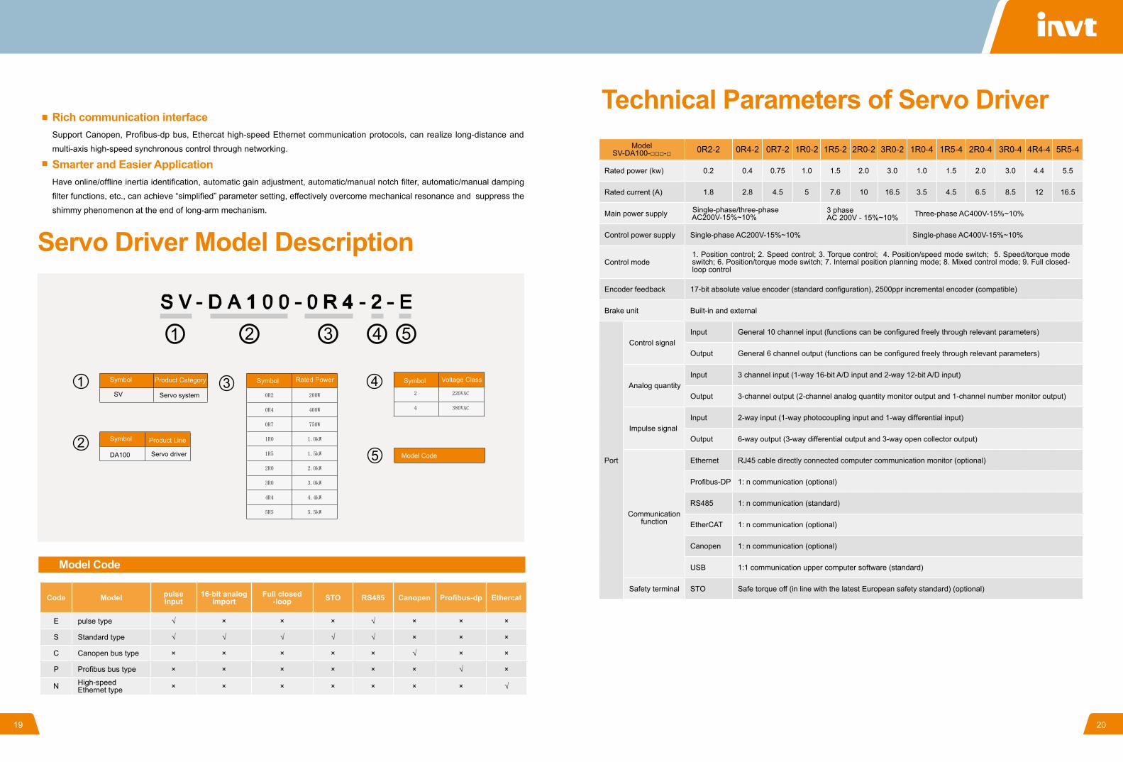
Code Model pulse input
16-bit analog import
Full closed-loop STO RS485 Canopen Profibus-dp Ethercat
E pulse type √ × × × √ × × ×
S Standard type √ √ √ √ √ × × ×
C Canopen bus type × × × × × √ × ×
P Profibus bus type × × × × × × √ ×
N High-speed Ethernet type × × × × × × × √
Servo Driver Model Description
Symbol Symbol SymbolRated Power
Model Code
Voltage ClassProduct Category
SV Servo system
Product LineSymbol
DA100 Servo driver
Model Code
Rich communication interfaceSupport Canopen, Profibus-dp bus, Ethercat high-speed Ethernet communication protocols, can realize long-distance and
multi-axis high-speed synchronous control through networking.
Smarter and Easier ApplicationHave online/offline inertia identification, automatic gain adjustment, automatic/manual notch filter, automatic/manual damping
filter functions, etc., can achieve “simplified” parameter setting, effectively overcome mechanical resonance and suppress the
shimmy phenomenon at the end of long-arm mechanism.
Technical Parameters of Servo DriverModel
SV-DA100-□□□-□ 0R2-2 0R4-2 0R7-2 1R0-2 1R5-2 2R0-2 3R0-2 1R0-4 1R5-4 2R0-4 3R0-4 4R4-4 5R5-4
Rated power (kw) 0.2 0.4 0.75 1.0 1.5 2.0 3.0 1.0 1.5 2.0 3.0 4.4 5.5
Rated current (A) 1.8 2.8 4.5 5 7.6 10 16.5 3.5 4.5 6.5 8.5 12 16.5
Main power supply Single-phase/three-phase AC200V-15%~10% Three-phase AC400V-15%~10%
Control power supply Single-phase AC200V-15%~10% Single-phase AC400V-15%~10%
Control mode
Encoder feedback 17-bit absolute value encoder (standard configuration), 2500ppr incremental encoder (compatible)
Brake unit Built-in and external
Port
Control signal Input General 10 channel input (functions can be configured freely through relevant parameters)
Output General 6 channel output (functions can be configured freely through relevant parameters)
Analog quantity Input 3 channel input (1-way 16-bit A/D input and 2-way 12-bit A/D input)
Output 3-channel output (2-channel analog quantity monitor output and 1-channel number monitor output)
Impulse signal Input 2-way input (1-way photocoupling input and 1-way differential input)
Output 6-way output (3-way differential output and 3-way open collector output)
Communication
function
Ethernet RJ45 cable directly connected computer communication monitor (optional)
Profibus-DP 1: n communication (optional)
RS485 1: n communication (standard)
EtherCAT 1: n communication (optional)
Canopen 1: n communication (optional)
USB 1:1 communication upper computer software (standard)
Safety terminal STO Safe torque off (in line with the latest European safety standard) (optional)
1. Position control; 2. Speed control; 3. Torque control; 4. Position/speed mode switch; 5. Speed/torque mode switch; 6. Position/torque mode switch; 7. Internal position planning mode; 8. Mixed control mode; 9. Full closed-loop control
19 20
3 phase AC 200V - 15%~10%
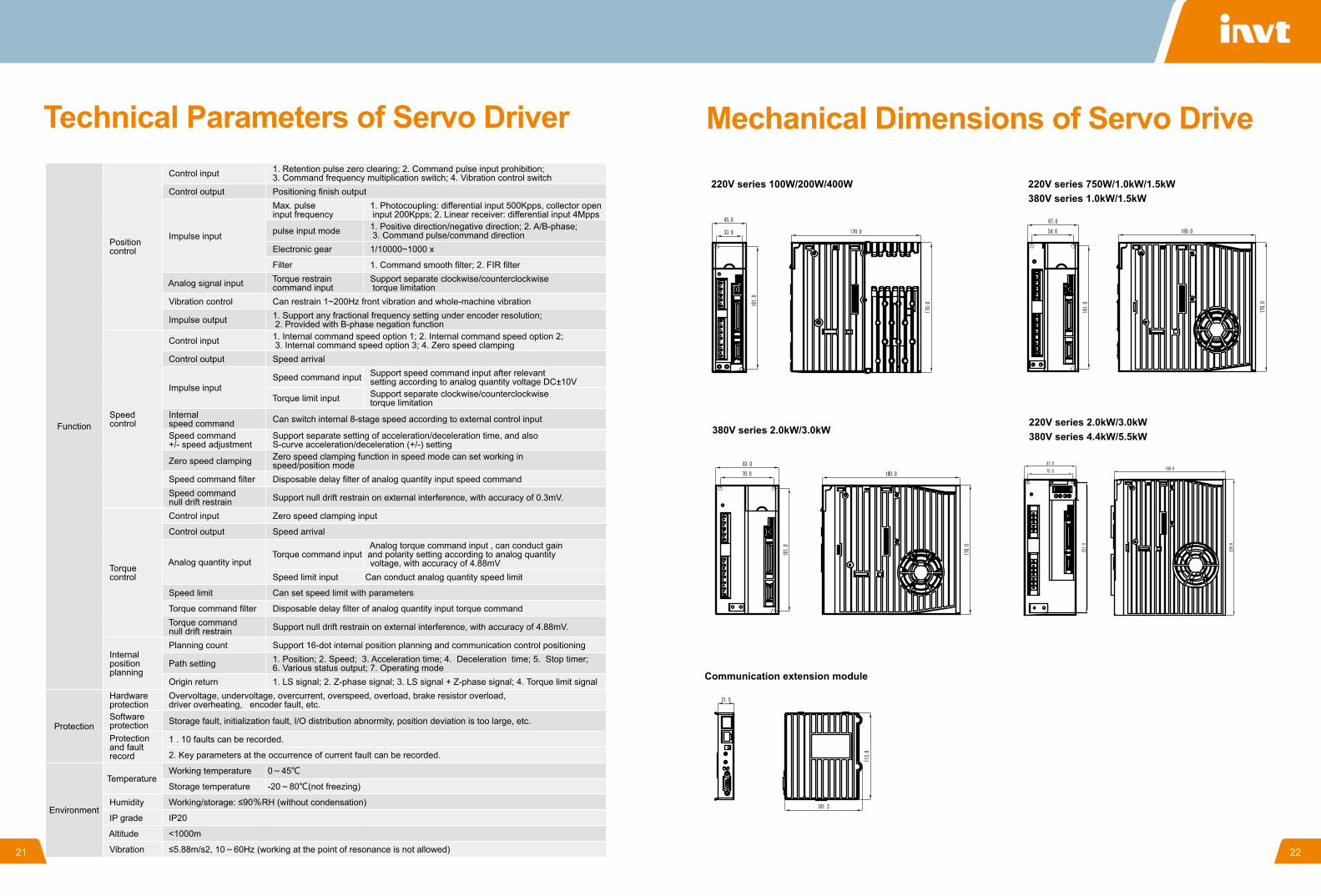
Technical Parameters of Servo Driver
Function
Position control
Control input 1. Retention pulse zero clearing; 2. Command pulse input prohibition; 3. Command frequency multiplication switch; 4. Vibration control switch
Control output Positioning finish output
Impulse input
Max. pulse input frequency
1. Photocoupling: differential input 500Kpps, collector open input 200Kpps; 2. Linear receiver: differential input 4Mpps
pulse input mode 1. Positive direction/negative direction; 2. A/B-phase; 3. Command pulse/command direction
Electronic gear 1/10000~1000 x
Filter 1. Command smooth filter; 2. FIR filter
Analog signal input Torque restrain command input
Support separate clockwise/counterclockwise torque limitation
Vibration control Can restrain 1~200Hz front vibration and whole-machine vibration
Impulse output 1. Support any fractional frequency setting under encoder resolution; 2. Provided with B-phase negation function
Speed control
Control input 1. Internal command speed option 1; 2. Internal command speed option 2; 3. Internal command speed option 3; 4. Zero speed clamping
Control output Speed arrival
Impulse input Speed command input Support speed command input after relevant
setting according to analog quantity voltage DC±10V
Torque limit input Support separate clockwise/counterclockwise torque limitation
Internal speed command Can switch internal 8-stage speed according to external control input
Speed command +/- speed adjustment
Support separate setting of acceleration/deceleration time, and also S-curve acceleration/deceleration (+/-) setting
Zero speed clamping Zero speed clamping function in speed mode can set working in speed/position mode
Speed command filter Disposable delay filter of analog quantity input speed command Speed command null drift restrain Support null drift restrain on external interference, with accuracy of 0.3mV.
Torque control
Control input Zero speed clamping input
Control output Speed arrival
Analog quantity input Torque command input
Analog torque command input , can conduct gain and polarity setting according to analog quantity voltage, with accuracy of 4.88mV
Speed limit input Can conduct analog quantity speed limit
Speed limit Can set speed limit with parameters
Torque command filter Disposable delay filter of analog quantity input torque command Torque command null drift restrain Support null drift restrain on external interference, with accuracy of 4.88mV.
Internal position planning
Planning count Support 16-dot internal position planning and communication control positioning
Path setting 1. Position; 2. Speed; 3. Acceleration time; 4. Deceleration time; 5. Stop timer; 6. Various status output; 7. Operating mode
Origin return 1. LS signal; 2. Z-phase signal; 3. LS signal + Z-phase signal; 4. Torque limit signal
Protection
Hardware protection
Overvoltage, undervoltage, overcurrent, overspeed, overload, brake resistor overload, driver overheating, encoder fault, etc.
Software protection Storage fault, initialization fault, I/O distribution abnormity, position deviation is too large, etc.
Protection and fault record
1 . 10 faults can be recorded.
2. Key parameters at the occurrence of current fault can be recorded.
Environment
Temperature Working temperature 0~45℃
Storage temperature -20~80℃(not freezing)
Humidity Working/storage: ≤90%RH (without condensation)
IP grade IP20
Altitude <1000m
Vibration ≤5.88m/s2, 10~60Hz (working at the point of resonance is not allowed)
Mechanical Dimensions of Servo Drive
220V series 100W/200W/400W
380V series 2.0kW/3.0kW
Communication extension module
220V series 750W/1.0kW/1.5kW380V series 1.0kW/1.5kW
220V series 2.0kW/3.0kW 380V series 4.4kW/5.5kW
21 22
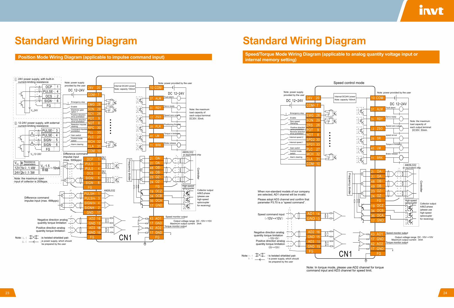
Standard Wiring Diagram
24V power supply, with built-in current-limiting resistance
12-24V power supply, with external current-limiting resistance
Resistance parameters
Note: power supply provided by the user
Gain switch
Emergency stop
Enable
Electronic gear option 1Positive direction drive prohibition Reverse direction drive prohibition Retention impulse clearingCommand impulse prohibition
Control mode switch
Alarm clearing
Internal DC24V powerNote: capacity 100mA
Note: power provided by the user
Note: the maximum load capacity of each output terminal:
Fault alarm
Servo ready
Speed zero output
Positioning finished
Torque in limitation
Brake release
Note: the maximum open input of collector is 200kpps.
Difference command impulse input (max. 4Mkpps)
Negative direction analogquantity torque limitation
Positive direction analogquantity torque limitation
Difference command impulse input (max. 500kpps) Frequency divider
Controller
Note: is twisted shielded pair.is power supply, which should be prepared by the user
Collector output A/B/Z-phase (please use high-speed optocoupler for receiving)
Speed monitor output
Torque monitor output
Output voltage range DC -10V~+10VMaximum output current 3mA
or equivalent chip
Position Mode Wiring Diagram (applicable to impulse command input)
High-speed optocoupler
Standard Wiring DiagramSpeed/Torque Mode Wiring Diagram (applicable to analog quantity voltage input or internal memory setting)
Note: power supply provided by the user
Gain switch
Internal speed 2
Internal speed 1
Emergency stop
Enable
Positive direction drive prohibition
Zero speed clamping
Reverse direction drive prohibition
Control mode switch
Alarm clearing
Internal DC24V powerNote: capacity 100mA
Note: power provided by the user
Note: the maximum load capacity of each output terminal:
Fault alarm
Servo ready
Speed zero output
speed arrival
Torque in limitation
Brake release
When non-standard models of our company are selected, AD1 channel will be invalid.
Please adopt AD3 channel and confirm that parameter P3.70 is a “speed command”.
Speed command input
Negative direction analogquantity torque limitation
Positive direction analogquantity torque limitation
Frequency divider
Controller
Note: is twisted shielded pair.is power supply, which should be prepared by the user
Collector output A/B/Z-phase (please use high-speed optocoupler for receiving)
Speed monitor output
Torque monitor output
Output voltage range DC -10V~+10VMaximum output current 3mA
or equivalent chip
High-speed optocoupler
Note: In torque mode, please use AD2 channel for torque command input and AD3 channel for speed limit.
Speed control mode
23 24
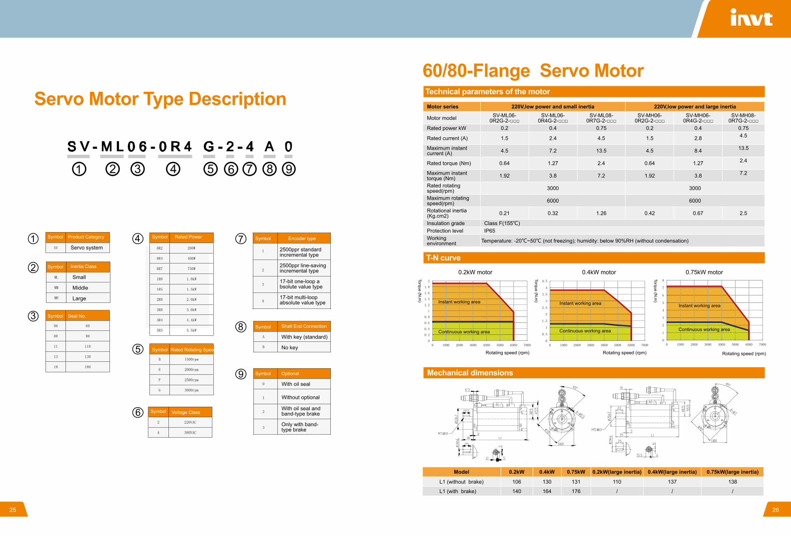
Symbol
Symbol
Symbol
Symbol
Symbol
Symbol
Symbol
Symbol
Symbol
Product Category
Optional
Voltage Class
Shaft End Connection
Encoder type
Seat No.
Rated Power
Inertia Class
Rated Rotating Speed
Servo system
Small
Middle
Large
2500ppr standard incremental type
2500ppr line-saving incremental type
17-bit one-loop absolute value type
17-bit multi-loop absolute value type
With oil seal
Without optional
With key (standard)
No key
Servo Motor Type Description
With oil seal and band-type brake
Only with band-type brake
60/80-Flange Servo MotorTechnical parameters of the motor
T-N curve
Mechanical dimensions
Motor series 220V,low power and small inertia 220V,low power and large inertia
Motor model SV-ML06-0R2G-2-□□□
SV-ML06-0R4G-2-□□□
SV-ML08-0R7G-2-□□□
SV-MH06-0R2G-2-□□□
SV-MH06-0R4G-2-□□□
SV-MH08-0R7G-2-□□□
Rated power kW 0.2 0.4 0.75 0.2 0.4 0.75
Rated current (A) 1.5 2.4 4.5 1.5 2.8 4.5
Maximum instant current (A) 4.5 7.2 13.5 4.5 8.4 13.5
Rated torque (Nm) 0.64 1.27 2.4 0.64 1.27 2.4
Maximum instant torque (Nm) 1.92 3.8 7.2 1.92 3.8 7.2
Rated rotating speed(rpm) 3000 3000
Maximum rotating speed(rpm) 6000 6000
Rotational inertia (Kg.cm2) 0.21 0.32 1.26 0.42 0.67 2.5
Insulation grade Class F(155℃) Protection level IP65 Working environment Temperature: -20℃~50℃ (not freezing); humidity: below 90%RH (without condensation)
0.2kW motor
Instant working area Instant working area Instant working area
Continuous working area Continuous working area Continuous working area
Rotating speed (rpm) Rotating speed (rpm) Rotating speed (rpm)
Torque (N.m
)
Torque (N.m
)
Torque (N.m
)
0.4kW motor 0.75kW motor
Model 0.2kW 0.4kW 0.75kW 0.2kW(large inertia) 0.4kW(large inertia) 0.75kW(large inertia)
L1 (without brake) 106 130 131 110 137 138
L1 (with brake) 140 164 176 / / /
25 26
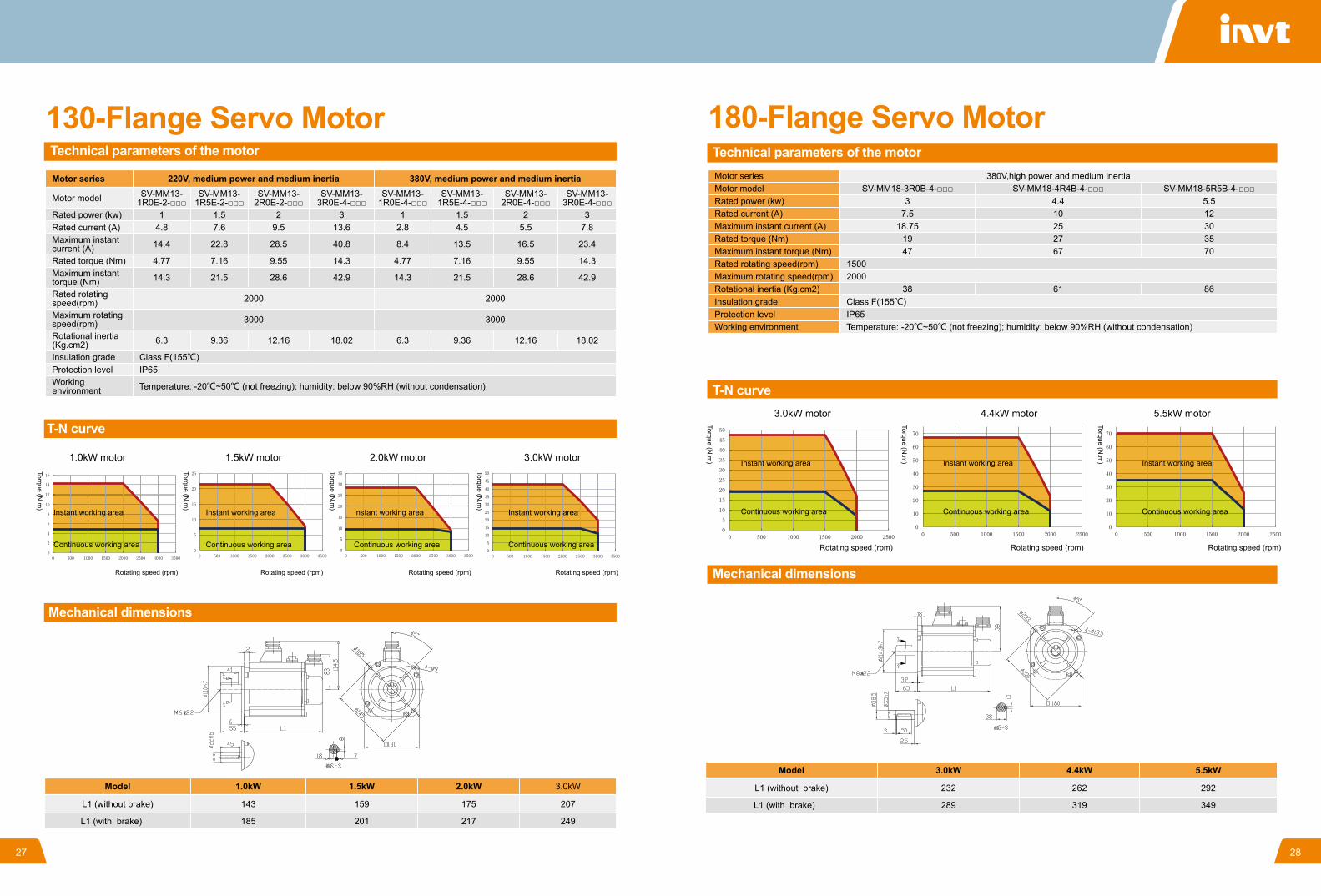
130-Flange Servo MotorTechnical parameters of the motor
T-N curve
Mechanical dimensions
Motor series 220V, medium power and medium inertia 380V, medium power and medium inertia
Motor model SV-MM13-1R0E-2-□□□
SV-MM13-1R5E-2-□□□
SV-MM13-2R0E-2-□□□
SV-MM13-3R0E-4-□□□
SV-MM13-1R0E-4-□□□
SV-MM13-1R5E-4-□□□
SV-MM13-2R0E-4-□□□
SV-MM13-3R0E-4-□□□
Rated power (kw) 1 1.5 2 3 1 1.5 2 3 Rated current (A) 4.8 7.6 9.5 13.6 2.8 4.5 5.5 7.8 Maximum instant current (A) 14.4 22.8 28.5 40.8 8.4 13.5 16.5 23.4
Rated torque (Nm) 4.77 7.16 9.55 14.3 4.77 7.16 9.55 14.3 Maximum instant torque (Nm) 14.3 21.5 28.6 42.9 14.3 21.5 28.6 42.9
Rated rotating speed(rpm) 2000 2000
Maximum rotating speed(rpm) 3000 3000
Rotational inertia (Kg.cm2) 6.3 9.36 12.16 18.02 6.3 9.36 12.16 18.02
Insulation grade Class F(155℃) Protection level IP65 Working environment Temperature: -20℃~50℃ (not freezing); humidity: below 90%RH (without condensation)
1.0kW motor
Instant working area Instant working area Instant working area Instant working area
Continuous working area Continuous working area Continuous working area Continuous working area
Rotating speed (rpm) Rotating speed (rpm) Rotating speed (rpm) Rotating speed (rpm)
Torque (N.m
)
Torque (N.m
)
Torque (N.m
)
Torque (N.m
)
1.5kW motor 2.0kW motor 3.0kW motor
Model 1.0kW 1.5kW 2.0kW 3.0kW
L1 (without brake) 143 159 175 207
L1 (with brake) 185 201 217 249
180-Flange Servo MotorTechnical parameters of the motor
T-N curve
Mechanical dimensions
Motor series 380V,high power and medium inertia Motor model SV-MM18-3R0B-4-□□□ SV-MM18-4R4B-4-□□□ SV-MM18-5R5B-4-□□□ Rated power (kw) 3 4.4 5.5 Rated current (A) 7.5 10 12 Maximum instant current (A) 18.75 25 30 Rated torque (Nm) 19 27 35 Maximum instant torque (Nm) 47 67 70 Rated rotating speed(rpm) 1500 Maximum rotating speed(rpm) 2000 Rotational inertia (Kg.cm2) 38 61 86 Insulation grade Class F(155℃) Protection level IP65 Working environment Temperature: -20℃~50℃ (not freezing); humidity: below 90%RH (without condensation)
3.0kW motor
Instant working area Instant working area Instant working area
Continuous working area Continuous working area Continuous working area
Rotating speed (rpm) Rotating speed (rpm) Rotating speed (rpm)
Torque (N.m
)
Torque (N.m
)
Torque (N.m
)
4.4kW motor 5.5kW motor
Model 3.0kW 4.4kW 5.5kW
L1 (without brake) 232 262 292
L1 (with brake) 289 319 349
27 28
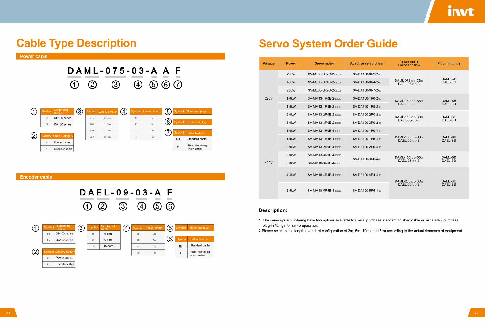
Cable Type DescriptionPower cable
Encoder cable
Symbol
Symbol
Symbol Symbol
Symbol
Symbol
Symbol
Symbol
Symbol
Symbol
Symbol
Symbol
Symbol
Supporting Series
Supporting Series
Wire Diameter Cable Length
Cable Length
Cable Texture
Cable Texture
Driver end plug
Motor end plug
Motor end plug
Cable Category
Cable Category
Number of Cores
DB100 series
DA100 series
DB100 series
DA100 series
6-core
9-core
15-core
Nil
F
F
Nil
Standard cable
Flexible drag chain cable
Standard cable
Flexible drag chain cable
Power cable
Encoder cable
Power cable
Encoder cable
Servo System Order GuideVoltage Power Servo motor Adaptive servo driver Power cable
Encoder cable Plug-in fittings
220V
200W SV-ML06-0R2G-2-□□□ SV-DA100-0R2-2-□
DAML-075-□□-CB□DAEL-06-□□-C
DAML-CB DAEL-BC 400W SV-ML06-0R4G-2-□□□ SV-DA100-0R4-2-□
750W SV-ML08-0R7G-2-□□□ SV-DA100-0R7-2-□
1.0kW SV-MM13-1R0E-2-□□□ SV-DA100-1R0-2-□DAML-150-□□-BB□
DAEL-06-□□-BDAML-BB DAEL-BB
1.5kW SV-MM13-1R5E-2-□□□ SV-DA100-1R5-2-□
2.0kW SV-MM13-2R0E-2-□□□ SV-DA100-2R0-2-□DAML-150-□□-BD□
DAEL-06-□□-BDAML-BD DAEL-BB
3.0kW SV-MM13-3R0E-2-□□□ SV-DA100-3R0-2-□
400V
1.0kW SV-MM13-1R0E-4-□□□ SV-DA100-1R0-4-□
DAML-150-□□-BB□DAEL-06-□□-B
DAML-BB DAEL-BB 1.5kW SV-MM13-1R5E-4-□□□ SV-DA100-1R5-4-□
2.0kW SV-MM13-2R0E-4-□□□ SV-DA100-2R0-4-□
3.0kW SV-MM13-3R0E-4-□□□SV-DA100-3R0-4-□ DAML-150-□□-BB□
DAEL-06-□□-BDAML-BB DAEL-BB
3.0kW SV-MM18-3R0B-4-□□□
4.4kW SV-MM18-4R4B-4-□□□ SV-DA100-4R4-4-□
DAML-250-□□-BD□DAEL-06-□□-B
DAML-BD DAEL-BB
5.5kW SV-MM18-5R5B-4-□□□ SV-DA100-5R5-4-□
Description:
1. The servo system ordering have two options available to users: purchase standard finished cable or separately purchase plug-in fittings for self-preparation;2.Please select cable length (standard configuration of 3m, 5m, 10m and 15m) according to the actual demands of equipment.
29 30
2
2
2
2
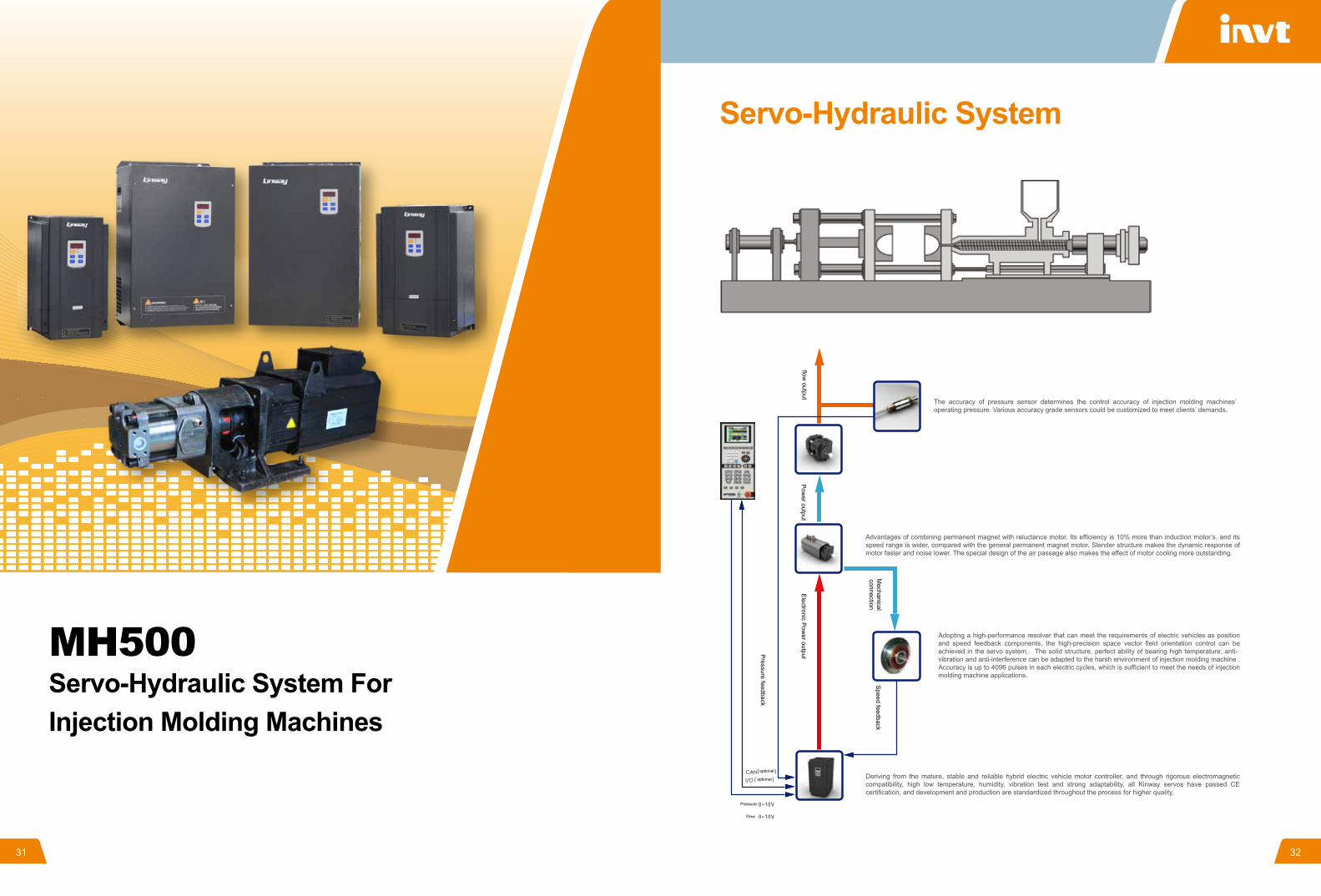
MH500 Servo-Hydraulic System For Injection Molding Machines
Servo-Hydraulic System
31 32
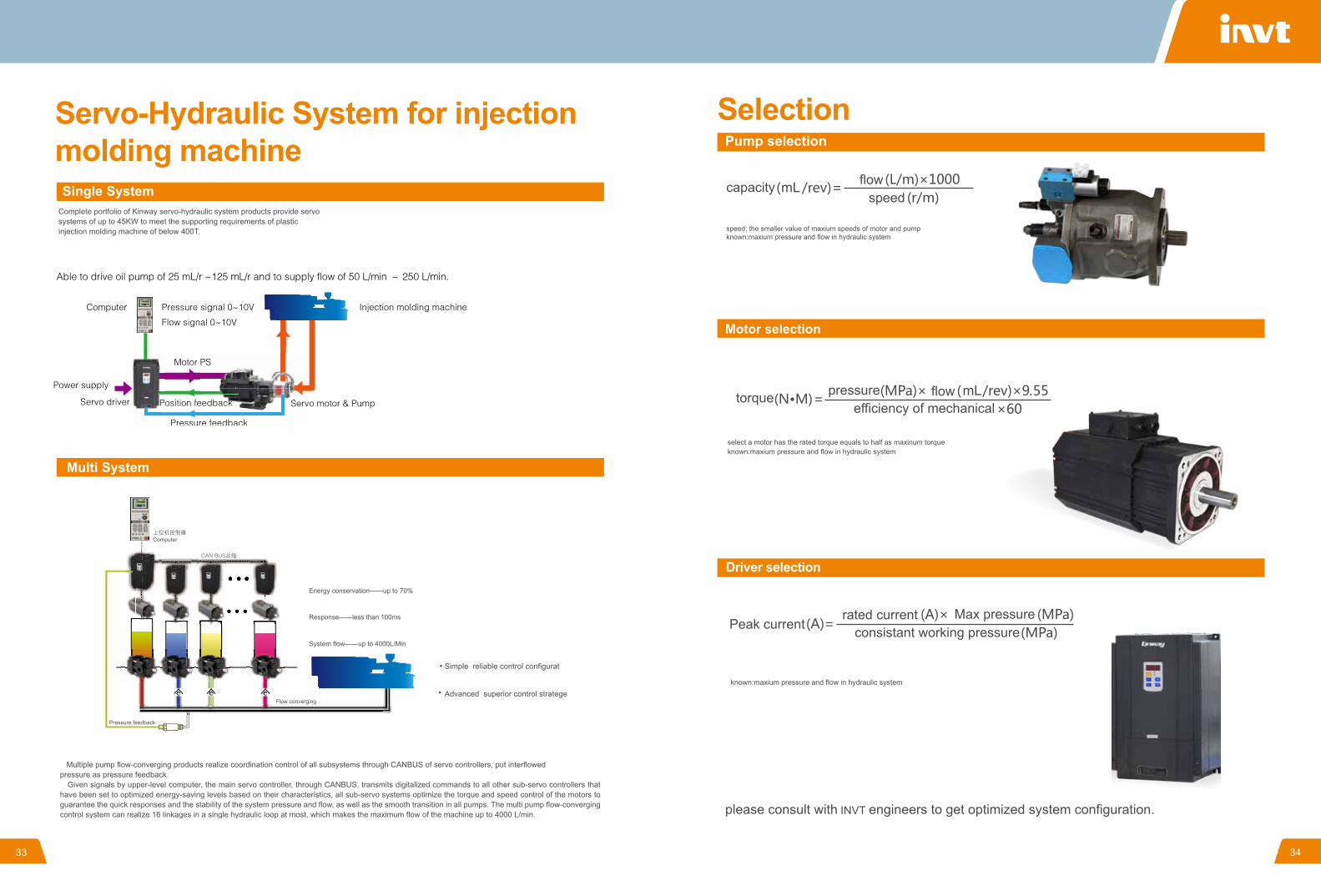
Servo-Hydraulic System for injection molding machine
Selection
33 34
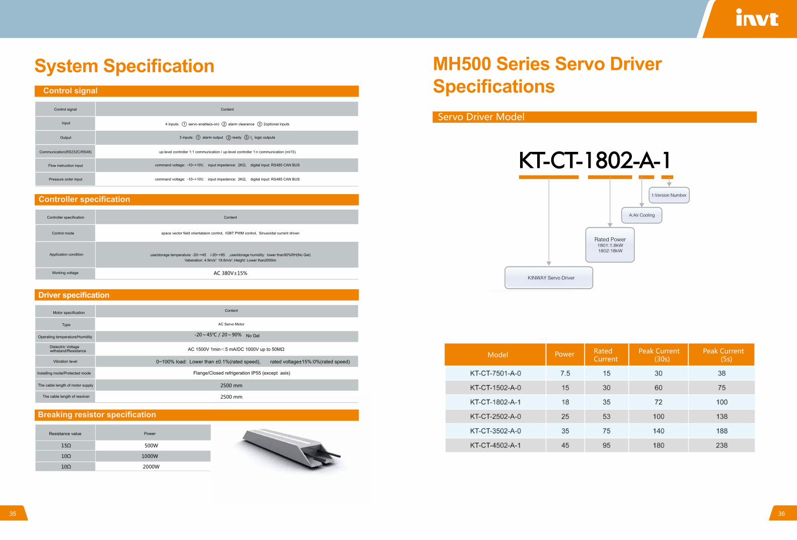
System Specification MH500 Series Servo Driver Specifications
35 36
Driver specification
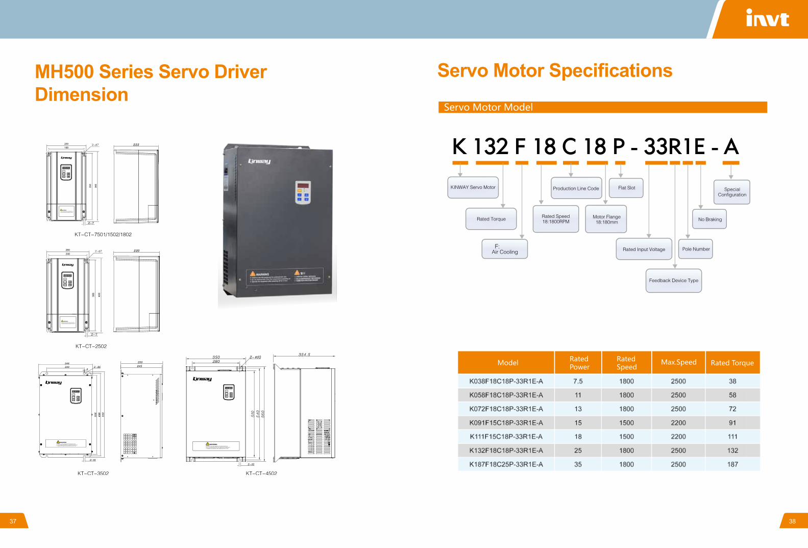
MH500 Series Servo Driver Dimension
Servo Motor Specifications
37 38

Servo Motor Dimension System interconnect diagram
39 40
Analog given 1 input +
Analog given 1 input -
Analog given 2 input +
Analog given 2 input -
feedback input+
feedback input-
Analog output1
Analog output2
Analog ground
Analog ground
given 10V reference power
fault reset signal
drive enable
programmable digital input1
programmable digital input2
control power input
digital signal ground
digital signal ground
servo ready-
servo ready+
alarm output-
alarm output+
programmable digital input 2 output-
programmable digital input 2 output+
terminal no.
input and output signals
signal definitionPC codecolor shielded cable to the drive cabinet
pressure sensor
power supply redground black/blue
output green
HMI cable
lead wire
view direction of connecting terminals
the length of motor resolver cable is 2.5m
Motor resolver connection definition
Motor aviation plug connecting with control panelwiring identification wiring identification
blue
blue/white
green/white
white/orange
white
green
orange
excitation signal+
excitation signal-
resolver sine input+
resolver sine input-
resolver cosine input+
resolver cosine input-
the length of motor power cable is 2.5m
power cablebraking resistor
Motor power connection definitionBlack
Black
Black
Black
Black
Black
Black
input filter
Input power supply
PE/grounding
gear pumps
bracket
motor
Auto Run
manual adjustmentforward backward
Cancel Enter
Monitor Set Adjust
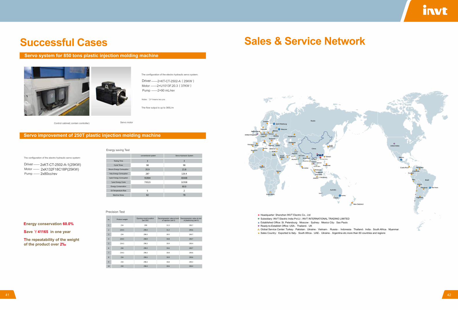
2xKT-CT-2502-A-1(25KW)2xK132F18C18P(25KW)2x80cc/rev
Successful Cases Sales & Service Network
Headquarter: Shenzhen INVT Electric Co., Ltd Subsidiary: INVT Electric India Pvt.Lt ; INVT INTERNATIONAL TRADING LIMITEDEstablished Office: St. Petersburg、Moscow、Sydney、Mexico City、Sao PauloReady-to-Establish Office: USA、Thailand、UKGlobal Service Center: Turkey、Pakistan、Ukraine、Vietnam、 Russia 、Indonesia、Thailand、India、South Africa、Myanmar Sales Country:Exported to Italy、South Africa、UAE、Ukraine、Argentina etc.more than 60 countries and regions
Hong Kong
41 42