Embed Size (px)
Citation preview

AC Servo Motor DriverSeries LECSm
Incremental Type/Series LECSA
Absolute Type/Series LECSB
Absolute Type/Series LECSC
Absolute Type/Series LECSS
Pulse Input Type/Positioning Type Page 604
Pulse Input Type Page 604
CC-Link Direct Input Type Page 604 SSCNET #Type Page 604
598
LE
FS
LE
FB
LE
LL
EJS
LE
JBL
EM
LE
YL
EY
GL
ES
LE
SH
LE
PY
LE
PS
LE
RL
EH
LEY-
X511
-LEF
S11
-LEJ
S25
A-
LEC
YMLE
CYU
LECS
S-T
LA
T3
Moto
rless
LEC
S
LE
C

599
AC Servo Motor Driver
Note 1) For positioning type, setting needs to be changed to use with maximum set values.Setup software (MR Configurator2™) LEC-MRC2 is required.
Note 2) Available when the Mitsubishi motion controller is used for the master equipment.
Positioning PulseNetwork
directinput
Control methodApplication/
FunctionCompatible motor
(100/200 VAC)
Series Setupsoftware
LEC-MRC2
Compatibleoption
100 W 200 W 400 W
LECSA(Pulse input type/Positioning type)
LECSB(Pulse input type)
LECSS (SSCNET 3 type)Compatible with Mitsubishi Electric’s servo system controller network
LECSC(CC-Link direct input type)
Up to7 points
Up to255 points
CC-LinkVer. 1.10
SSCNET 3
Note 1)Synchronous
Note 2)
Series LECS list
Incr
emen
tal T
ype
Ab
solu
te T
ype

Time
Settlingtime Settling
time
TimeS
peed
Spe
ed
Servo adjustment using auto gain tuning
With display setting function
Auto tuning function
Advanced vibration suppression control function
(With the front cover opened)LECSALECSB
(With the front cover opened)
LECSS(With the front cover opened)
LECSC
Series LECS
• Control the difference between command value and actual action
• Automatically suppress low frequency machine vibrations (up to 100 Hz)
One-touch servo adjustment
One-touch adjustment button
Display the monitor, parameter and alarm.
Display
Set parameters andmonitor display, etc.with push buttons.
Settings
Display
Control Baud rate, station number and the occupied station count.
Settings
Display the communication status with the driver, the alarm and the point table No.
Display the monitor, parameter and alarm.
Display
Set parameters andmonitor display, etc.with push buttons.
Settings
Display
Switches for selecting axis and switching to the test operation
Display the communication status with the driver and the alarm.
Settings
600
LE
FS
LE
FB
LE
LL
EJS
LE
JBL
EM
LE
YL
EY
GL
ES
LE
SH
LE
PY
LE
PS
LE
RL
EH
LEY-
X511
-LEF
S11
-LEJ
S25
A-
LEC
YMLE
CYU
LECS
S-T
LA
T3
Moto
rless
LEC
S
LE
C

System Construction
Incremental encoder compatible Series LECSA
Driver
DriverAbsolute encoder compatible Series LECSB
Power supplyfor I/O signal
24 VDC
Power supplySingle phase 100 to 120 VAC (50/60 Hz) 200 to 230 VAC (50/60 Hz)
Provided by customer
Battery (Accessory)
Part no.: LEC-MR-RB-
Part no.: (LEC-MR-J3BAT)
Provided by customer
Option
Option
Provided bycustomer
Power supplySingle phase 100 to 120 VAC (50/60 Hz) 200 to 230 VAC (50/60 Hz)
Three phase 200 to 230 VAC (50/60 Hz)
Provided by customer
Control circuit power supply24 VDC
Option
Regeneration option
Standard cable Robotic cableLE-CSM-S LE-CSM-R
Motor cable
Motor cable
Page 614
Page 614
Page 614
Main circuit power supply connector(Accessory)
Page 608 Setup software Page 616
Setup software Page 616
Page 614
Page 615 Page 608
Page 614
I/O connectorPart no.: LE-CSNA
Option Page 614I/O connector
Part no.: LE-CSNB
USB cablePart no.: LEC-MR-J3USB
Page 616USB cablePart no.: LEC-MR-J3USB
Analogmonitor outputRS-422
communication
Control circuit power supply connector(Accessory)
Page 609
Page 609
Control circuit power supply connector(Accessory)
Motor connector(Accessory)
Standard cable Robotic cableLE-CSB-S LE-CSB-R
Lock cable
Page 614
Page 614
Page 616
Lock cable
Standard cable Robotic cableLE-CSM-S LE-CSM-R
Standard cable Robotic cableLE-CSB-S LE-CSB-R
Standard cable Robotic cableLE-CSE-S LE-CSE-R
Encoder cable
Page 614Encoder cable
Provided by customer
PLC (Positioning unit)
Power supplyfor I/O signal
24 VDC
PLC (Positioning unit)
Standard cable Robotic cableLE-CSE-S LE-CSE-R
(Pulse input type/Positioning type)
(Pulse input type)
Part no.: LEC-MR-RB-
OptionRegeneration option
Page 615
Main circuit power supplyconnector(Accessory)
Page 609
PC
(MR Configurator2™)Part no.: LEC-MRC2
PC
(MR Configurator2™)Part no.: LEC-MRC2
Electric actuatorSlider typeBall screw drive
Series LEFSBelt driveSeries LEFB
Electric actuatorSlider typeBall screw drive
Series LEFSBelt driveSeries LEFB
Option
601

System Construction
Driver
PC
Provided bycustomer
Power supplySingle phase 100 to 120 VAC (50/60 Hz) 200 to 230 VAC (50/60 Hz)
Three phase 200 to 230 VAC (50/60 Hz)
Provided by customer
Standard cable Robotic cableLE-CSM-S LE-CSM-R
Standard cable Robotic cableLE-CSB-S LE-CSB-R
Standard cable Robotic cableLE-CSE-S LE-CSE-R
PLC (CC-Link master unit)
CC-Link connector Note)
(Accessory)
Driver
Power supplySingle phase 100 to 120 VAC (50/60 Hz) 200 to 230 VAC (50/60 Hz)
Three phase 200 to 230 VAC (50/60 Hz)
Provided by customer
Standard cable Robotic cableLE-CSM-S LE-CSM-R
Standard cable Robotic cableLE-CSB-S LE-CSB-R
Standard cable Robotic cableLE-CSE-S LE-CSE-R
PLC (Positioning unit/Motion controller)
SSCNET #optical cablePart no.: LE-CSS-
CN1ACN1B
CN1A
Absolute encoder compatible Series LECSC(CC-Link direct input type)
Absolute encoder compatible Series LECSS(SSCNET # type)
Part no.: LEC-MR-RB-
OptionRegeneration option
Page 615
Part no.: LEC-MR-RB-
OptionRegeneration option
Page 615
Motor cable Page 614
Page 614Lock cable
Motor cable Page 614
Page 614Lock cable
Page 614Encoder cable
Page 614Encoder cable
Main circuit power supplyconnector(Accessory)
Page 609
Main circuit power supplyconnector(Accessory)
Page 609
Page 609Control circuitpower supply connector(Accessory)
Page 609Motor connector(Accessory)
Battery (Accessory)Part no.: (LEC-MR-J3BAT)
Page 616
OptionPage 616USB cablePart no.: LEC-MR-J3USB
OptionPage 616USB cablePart no.: LEC-MR-J3USB
Setup software(MR Configurator2™)Part no.: LEC-MRC2
Page 616
PC
Setup software(MR Configurator2™)Part no.: LEC-MRC2
Page 616
Option Page 614I/O connector
Part no.: LE-CSNA
Power supplyfor I/O signal
24 VDC
RS-422communication
Page 609Control circuitpower supply connector(Accessory)
Page 609Motor connector(Accessory)
Battery (Accessory)Page 616
Part no.: (LEC-MR-J3BAT)
Option
Option Page 615
Page 614I/O connector
Part no.: LE-CSNS
Providedby
customer
Power supplyfor I/O signal
24 VDC
Electric actuatorSlider typeBall screw drive
Series LEFSBelt driveSeries LEFB
Electric actuatorSlider typeBall screw drive
Series LEFSBelt driveSeries LEFB
Note) Product number: K05A50230600 manufactured by Mitsubishi Electric System & Service Co., Ltd.
602
LE
FS
LE
FB
LE
LL
EJS
LE
JBL
EM
LE
YL
EY
GL
ES
LE
SH
LE
PY
LE
PS
LE
RL
EH
LEY-
X511
-LEF
S11
-LEJ
S25
A-
LEC
YMLE
CYU
LECS
S-T
LA
T3
Moto
rless
LEC
S
LE
C

Series LECSA (Pulse input type/ Positioning type)
Series LECS
Series LECSB (Pulse input type)
Series LECSC (CC-Link direct input type)
Series LECSS (SSCNET# type)
Incr
emen
tal T
ype
AC Servo Motor DriverA
bso
lute
Typ
ePower supply voltage 100 to 120 VAC
200 to 230 VAC
Motor capacity 100/200/400 W
Up to 7 positioning points by point table
Input type: Pulse input
Control encoder: Incremental 17-bit encoder (Resolution: 131072 pulse/rev)
Parallel input: 6 inputs output: 4 outputs
Input type: Pulse input
Control encoder: Absolute 18-bit encoder (Resolution: 262144 pulse/rev)
Parallel input: 10 inputs output: 6 outputs
Position data/speed data setting and operation start/stop
Positioning by up to 255 point tables (when 2 stations occupied)
Up to 32 drivers connectable (when 2 stations occupied) with CC-Link communication
Applicable Fieldbus protocol: CC-Link (Ver. 1.10, Max. communication speed: 10 Mbps)
Control encoder: Absolute 18-bit encoder (Resolution: 262144 pulse/rev)
Compatible with Mitsubishi Electric,s servo system controller network
Reduced wiring and SSCNET#optical cable for one-touch connection
SSCNET#optical cable provides enhanced noise resistance
Up to 16 drivers connectable with SSCNET#communication
Applicable Fieldbus protocol: SSCNET#(High-speed optical communication, Max. one-way communication speed: 50 Mbps)
Control encoder: Absolute 18-bit encoder (Resolution: 262144 pulse/rev)
LECS-P02-CS3e.indd 2 15.2.24 10:25:53 AM
603

6
5.5
5
130
120
40 135
CN3
CN2
CN1
CNP2
CNP1
50
130
120
5
CN3
CNP1
CNP2
CN1
CN2
6
6
For LECSA-S1,S3 For LECSA-S4
2 x ø6 Mounting hole(Bearing surface thickness 5)
2 x ø6 Mounting hole(Bearing surface thickness 5)
∗ Battery included.
CNP3
CNP2
CNP1CN3
CN1
CN2
CN4
CN6CN5
(14)
156
66
6
161
168
40 135 (For LECSB-S5, S7)170 (For LECSB-S8)6
Battery∗
ø6 Mounting hole(Bearing surface thickness 4)
How to Order
Series LECSB/LECSC/LECSSAbsolute TypeSeries LECSA (Pulse Input Type/Positioning Type)
Incremental TypeAC Servo Motor Driver
Dimensions
LECSA
LECSB
LECS 1A S1Driver type
Compatible motor type
Power supply voltage
* Only available for power supply voltage “200 to 230 VAC”.
LECSA LECSB LECSC LECSS
(Pulse Input Type) (CC-Link Direct Input Type) (SSCNET#Type)
Driver
Connectorname Description
CN1 I/O signal connector
CN2 Encoder connector
CN3 RS-422 communication connector
CN4 Battery connector
CN5 USB communication connector
CN6 Analog monitor connector
CNP1 Main circuit power supply connector
CNP2 Control circuit power supply connector
CNP3 Servo motor power connector
Connectorname Description
CN1 I/O signal connector
CN2 Encoder connector
CN3 USB communication connector
CNP1 Main circuit power supply connector
CNP2 Control circuit power supply connector
1 100 to 120 VAC, 50/60 Hz
2 200 to 230 VAC, 50/60 Hz
A Pulse input type/Positioning type(For incremental encoder)
B Pulse input type(For absolute encoder)
C CC-Link direct input type(For absolute encoder)
S SSCNET# type(For absolute encoder)
Symbol Type Capacity Encoder
S1 AC servo motor (S2) 100 WIncrementalS3 AC servo motor (S3) 200 W
S4 AC servo motor (S4)* 400 W
S5 AC servo motor (S6) 100 WAbsoluteS7 AC servo motor (S7) 200 W
S8 AC servo motor (S8)* 400 W
RoHS
LECS-P03-CS3e.indd 3 15.2.24 2:35:26 PM
604
How to Order
LEF LEJ LEY
Compatible actuators
AC Servo Motor DriverIncremental TypeSeries LECSA (Pulse Input Type/Positioning Type)
Absolute TypeSeries LECSB (Pulse Input Type) /LECSC (CC-Link Direct Input Type) /LECSS (SSCNET#Type)
LECSA LECSB LECSC LECSS
LE
FS
LE
FB
LE
LL
EJS
LE
JBL
EM
LE
YL
EY
GL
ES
LE
SH
LE
PY
LE
PS
LE
RL
EH
LEY-
X511
-LEF
S11
-LEJ
S25
A-
LEC
YMLE
CYU
LECS
S-T
LA
T3
Moto
rless
LEC
S
LE
C

6
6
615
6
40135 (For LECSC-S5, S7)
170 (For LECSC-S8)2 x ø6(Bearing surface thickness 4)
CNP3
CNP2
CNP1
CN2CN4
Battery∗
CN6
CN1
CN3
CN5
168
Battery∗6
6
615
6
40135 (For LECSS-S5, S7)
170 (For LECSS-S8)2 x ø6(Bearing surface thickness 4)
CNP3
CNP2
CNP1
CN2
CN4
CN1B
CN1A
CN3
CN5
168
Dimensions
LECSC
LECSS
* Battery included.
* Battery included.
Connector name Description
CN1A Front axis connector forSSCNET#optical cable
CN1B Rear axis connector forSSCNET#optical cable
CN2 Encoder connector
CN3 I/O signal connector
CN4 Battery connector
CN5 USB communication connector
CNP1 Main circuit power supply connector
CNP2 Control circuit power supply connector
CNP3 Servo motor power connector
Connector name Description
CN1 CC-Link connector
CN2 Encoder connector
CN3 RS-422 communication connector
CN4 Battery connector
CN5 USB communication connector
CN6 I/O signal connector
CNP1 Main circuit power supply connector
CNP2 Control circuit power supply connector
CNP3 Servo motor power connector
Series LECS
LECS-P04-CS3e.indd 4 14.2.19 0:04:34 PM
605

Specifications
Series LECSA
Series LECSB
*1 USB communication and RS422 communication cannot be performed at the same time.*2 If the command pulse train input is open collector method, it supports only to the sink (NPN) type interface. It does not correspond to the source (PNP)
type interface.
Model LECSA1-S1 LECSA1-S3 LECSA2-S1 LECSA2-S3 LECSA2-S4Compatible motor capacity [W] 100 200 100 200 400
Compatible encoder Incremental 17-bit encoder(Resolution: 131072 p/rev)
Main power supply
Power voltage [V] Single phase 100 to 120 VAC (50/60 Hz) Single phase 200 to 230 VAC (50/60 Hz)Allowable voltage fluctuation [V] Single phase 85 to 132 VAC Single phase 170 to 253 VACRated current [A] 3.0 5.0 1.5 2.4 4.5
Control power supply
Control power supply voltage [V] 24 VDCAllowable voltage fluctuation [V] 21.6 to 26.4 VDCRated current [A] 0.5
Parallel input 6 inputsParallel output 4 outputsMax. input pulse frequency [pps] 1 M (for differential receiver), 200 k (for open collector)*2
Function
In-position range setting [pulse] 0 to ±65535 (Command pulse unit)Error excessive ±3 rotationsTorque limit Parameter settingCommunication USB communication
Operating temperature range [°C] 0 to 55 (No freezing)Operating humidity range [%RH] 90 or less (No condensation)Storage temperature range [°C] –20 to 65 (No freezing)Storage humidity range [%RH] 90 or less (No condensation)Insulation resistance [MΩ] Between the housing and SG: 10 (500 VDC)Weight [g] 600 700
Model LECSB1-S5 LECSB1-S7 LECSB2-S5 LECSB2-S7 LECSB2-S8Compatible motor capacity [W] 100 200 100 200 400
Compatible encoder Absolute 18-bit encoder(Resolution: 262144 p/rev)
Main power supply
Power voltage [V] Single phase 100 to 120 VAC (50/60 Hz)Three phase 200 to 230 VAC (50/60 Hz)Single phase 200 to 230 VAC (50/60 Hz)
Allowable voltage fluctuation [V] Single phase 85 to 132 VACThree phase 170 to 253 VACSingle phase 170 to 253 VAC
Rated current [A] 3.0 5.0 0.9 1.5 2.6
Control power supply
Control power supply voltage [V] Single phase 100 to 120 VAC (50/60 Hz) Single phase 200 to 230 VAC (50/60 Hz) Allowable voltage fluctuation [V] Single phase 85 to 132 VAC Single phase 170 to 253 VAC Rated current [A] 0.4 0.2
Parallel input 10 inputsParallel output 6 outputsMax. input pulse frequency [pps] 1 M (for differential receiver), 200 k (for open collector)*2
Function
In-position range setting [pulse] 0 to ±10000 (Command pulse unit)Error excessive ±3 rotationsTorque limit Parameter setting or external analog input setting (0 to 10 VDC)Communication USB communication, RS422 communication*1
Operating temperature range [°C] 0 to 55 (No freezing)Operating humidity range [%RH] 90 or less (No condensation)Storage temperature range [°C] –20 to 65 (No freezing)Storage humidity range [%RH] 90 or less (No condensation)Insulation resistance [MΩ] Between the housing and SG: 10 (500 VDC)Weight [g] 800 1000
AC Servo Motor Driver Series LECS
LECS-P05-CS3e.indd 5 15.10.8 5:14:08 PM
606
LE
FS
LE
FB
LE
LL
EJS
LE
JBL
EM
LE
YL
EY
GL
ES
LE
SH
LE
PY
LE
PS
LE
RL
EH
LEY-
X511
-LEF
S11
-LEJ
S25
A-
LEC
YMLE
CYU
LECS
S-T
LA
T3
Moto
rless
LEC
S
LE
C
A

Series LECSC
*1 If the system comprises of both CC-Link Ver. 1.00 and Ver. 1.10 compliant cables, Ver. 1.00 specifications are applied to the overall cable length and the cable length between stations.*2 USB communication and RS422 communication cannot be performed at the same time.
Specifications
Series LECSSModel LECSS1-S5 LECSS1-S7 LECSS2-S5 LECSS2-S7 LECSS2-S8
Compatible motor capacity [W] 100 200 100 200 400
Compatible encoder Absolute 18-bit encoder(Resolution: 262144 p/rev)
Main power supply
Power voltage [V]Single phase 100 to 120 VAC
(50/60 Hz)Three phase 200 to 230 VAC (50/60 Hz)Single phase 200 to 230 VAC (50/60 Hz)
Allowable voltage fluctuation [V] Single phase 85 to 132 VACThree phase 170 to 253 VACSingle phase 170 to 253 VAC
Rated current [A] 3.0 5.0 0.9 1.5 2.6
Control power supply
Control power supply voltage [V]Single phase 100 to 120 VAC
(50/60 Hz)Single phase 200 to 230 VAC
(50/60 Hz)Allowable voltage fluctuation [V] Single phase 85 to 132 VAC Single phase 170 to 253 VAC Rated current [A] 0.4 0.2
Applicable Fieldbus protocol SSCNET# (High-speed optical communication)Communication function USB communicationOperating temperature range [°C] 0 to 55 (No freezing)Operating humidity range [%RH] 90 or less (No condensation)Storage temperature range [°C] –20 to 65 (No freezing)Storage humidity range [%RH] 90 or less (No condensation)Insulation resistance [MΩ] Between the housing and SG: 10 (500 VDC)Weight [g] 800 1000
Model LECSC1-S5 LECSC1-S7 LECSC2-S5 LECSC2-S7 LECSC2-S8Compatible motor capacity [W] 100 200 100 200 400
Compatible encoder Absolute 18-bit encoder(Resolution: 262144 p/rev)
Main power supply
Power voltage [V]Single phase 100 to 120 VAC
(50/60 Hz)Three phase 200 to 230 VAC (50/60 Hz)Single phase 200 to 230 VAC (50/60 Hz)
Allowable voltage fluctuation [V] Single phase 85 to 132 VACThree phase 170 to 253 VACSingle phase 170 to 253 VAC
Rated current [A] 3.0 5.0 0.9 1.5 2.6
Control power supply
Control power supply voltage [V]Single phase 100 to 120 VAC
(50/60 Hz)Single phase 200 to 230 VAC
(50/60 Hz)Allowable voltage fluctuation [V] Single phase 85 to 132 VAC Single phase 170 to 253 VAC Rated current [A] 0.4 0.2
Communication specifications
Applicable Fieldbus protocol (Version) CC-Link communication (Ver. 1.10)Connection cable CC-Link Ver. 1.10 compliant cable (Shielded 3-core twisted pair cable)*1
Remote station number 1 to 64
Cablelength
Communication speed [bps] 16 k 625 k 2.5 M 5 M 10 MMaximum overall cable length [m] 1200 900 400 160 100Cable length between stations [m] 0.2 or more
I/O occupation area (Inputs/Outputs)
1 station occupied (Remote I/O 32 points/32 points)/(Remote register 4 words/4 words)2 stations occupied (Remote I/O 64 points/64 points)/(Remote register 8 words/8 words)
Number of connectable driversUp to 42 (when 1 station is occupied by 1 driver), Up to 32 (when 2 stations are occupied by1 driver), when there are only remote device stations.
Command method
Remote register input Available with CC-Link communication (2 stations occupied)
Point table No. input
Available with CC-Link communication, RS422 communicationCC-Link communication (1 station occupied): 31 pointsCC-Link communication (2 stations occupied): 255 pointsRS422 communication: 255 points
Indexer positioning inputAvailable with CC-Link communicationCC-Link communication (1 station occupied): 31 pointsCC-Link communication (2 stations occupied): 255 points
Communication function USB communication, RS-422 communication*2
Operating temperature range [°C] 0 to 55 (No freezing)Operating humidity range [%RH] 90 or less (No condensation)Storage temperature range [°C] –20 to 65 (No freezing)Storage humidity range [%RH] 90 or less (No condensation)Insulation resistance [MΩ] Between the housing and SG: 10 (500 VDC)Weight [g] 800 1000
Series LECS
LECS-P06-CS3e.indd 6 14.2.8 9:52:56 PM
607

Main circuit power supplySingle phase 200 to 230 VACorSingle phase 100 to 120 VAC
Control circuit power supply24 VDC
L1
CNP1NFB MCBuilt-in
regenerative resistor
Regeneration option
CN2
L2
P
U
V
W
U MotorV
WM
C
+24V
CNP2
0V
EncoderCircuit protector
L1
L2
P
C
U
V
W
24V
0V
Power Supply Wiring Example: LECSA
LECSA-
* Accessory
* Accessory
Main Circuit Power Supply Connector: CNP1
Control Circuit Power Supply Connector: CNP2
Terminal name Function Details
24V Control circuit power supply (24 V)
24 V side of the control circuit power supply (24 VDC) supplied to the driver
0V Control circuit power supply (0 V)
0 V side of the control circuit power supply (24 VDC) supplied to the driver
Terminal name Function Details
Protective earth (PE) Should be grounded by connecting the servo motor’s earthterminal and the control panel’s protective earth (PE).
L1 Main circuitpower supply
Connect the main circuit power supply.LECSA1: Single phase 100 to 120 VAC, 50/60 HzLECSA2: Single phase 200 to 230 VAC, 50/60 HzL2
P
Regeneration option
Terminal to connect regeneration optionLECSA-S1: Not connected at time of shipping.LECSA-S3, S4: Connected at time of shipping.* If regeneration option is required for “Model Selection”, connect to this terminal.
C
U Servo motor power (U)Connect to motor cable (U, V, W).V Servo motor power (V)
W Servo motor power (W)
AC Servo Motor Driver Series LECS
LECS-P07-CS3e.indd 7 14.1.31 8:08:10 PM
608
LE
FS
LE
FB
LE
LL
EJS
LE
JBL
EM
LE
YL
EY
GL
ES
LE
SH
LE
PY
LE
PS
LE
RL
EH
LEY-
X511
-LEF
S11
-LEJ
S25
A-
LEC
YMLE
CYU
LECS
S-T
LA
T3
Moto
rless
LEC
S
LE
C

L1
CNP1NFB MCCNP3
PE
CN2
Open
P1
P2
L2
U
V
W
U MotorV
WM
N
P
CNP2
C
L21
D
L11Encoder
Regeneration option
L1
CNP1NFB MCCNP3
PE
CN2
L2
P1
P2
L3
U
V
W
U MotorV
WM
N
P
CNP2
C
L21
D
L11Encoder
Regeneration option
L1
CNP1NFB MCCNP3
PE
CN2
L2
P1
P2
L3
U
V
W
U MotorV
WM
N(–)
P(+)
CNP2
C
L21
D
L11Encoder
Regeneration option
L1
L2
L3
N
P1
P2
P
C
D
L11
L21
U
V
W
Main Circuit Power Supply Connector: CNP1 * Accessory
* Accessory
* Accessory
Power Supply Wiring Example: LECSB, LECSC, LECSS
LECSB1-LECSC1-LECSS1-
LECSB2-LECSC2-LECSS2-
For three phase 200 VAC
Three phase200 to 230 VAC
For single phase 200 VAC
Note) For single phase 200 to 230 VAC, power supply should be connected to L1 and L2 terminals, with nothing connected to L3.
Single phase200 to 230 VAC
Single phase100 to 120 VAC
Control Circuit Power Supply Connector: CNP2
Motor Connector: CNP3
LECSBFront view example
Terminal name Function DetailsP
Regeneration option
Connect between P and D. (Connected at time of shipping.)* If regeneration option is required for “Model Selection”, connect to this
terminal.CD
L11Control circuit power supply
Connect the control circuit power supply.LECSB1/LECSC1/LECSS1: Single phase 100 to 120 VAC, 50/60 Hz Connection terminal: L11,L21
LECSB2/LECSC2/LECSS2: Single phase 200 to 230 VAC, 50/60 Hz Connection terminal: L11,L21
Three phase 200 to 230 VAC, 50/60 Hz Connection terminal: L11,L21L21
Terminal name Function DetailsU Servo motor power (U)
Connect to motor cable (U, V, W)V Servo motor power (V)W Servo motor power (W)
Terminal name Function Details
L1
Main circuitpower supply
Connect the main circuit power supply.LECSB1/LECSC1/LECSS1: Single phase 100 to 120 VAC, 50/60 Hz Connection terminal: L1,L2
LECSB2/LECSC2/LECSS2: Single phase 200 to 230 VAC, 50/60 Hz Connection terminal: L1,L2
Three phase 200 to 230 VAC, 50/60 Hz Connection terminal: L1,L2,L3
L2
L3
N Do not connect.P1
Connect between P1 and P2. (Connected at time of shipping.)P2
Series LECS
LECS-P08-CS3e.indd 8 14.1.31 8:09:47 PM
609
FX3U-MT/ES(Manufactured by Mitsubishi Electric Corporation)
PLC
CNP1
Sequencer power supply
PE
S/S
24V
0V
L
N
S/SY000
COM1
Y010
COM3
COM2
X
XX
Y004
LECSA
24 VDC
CN1
DICOM
OPC
DOCOM
PP
NP
CR
RD
LG
SD
INP
OP
Note 4)
Note 2)CN1
CN1
10 m or less
2 m or less Note 5)
10 m or less
Note 1)
1
2
13
23
25
5
11
14
Plate
10
21
9
12
15
Plate
20
ALM
EM1Forced stop
Servo ON
Reset
Forward rotation stroke end
Reverse rotation stroke end
8
SON 4
RES 3
LSP 6
LSN 7
MBR
LA
16 LAR
17 LB
18 LBR
19 LZ
SD
LZR
14 LG
Failure Note 3)
Electromagneticbrake interlock
A-phase pulse encoder(Differential line driver)
B-phase pulse encoder(Differential line driver)
Z-phase pulse encoder(Differential line driver)
Control common
RA1
RA2
Note 4) Note 4)
Note 6)
Note 6)
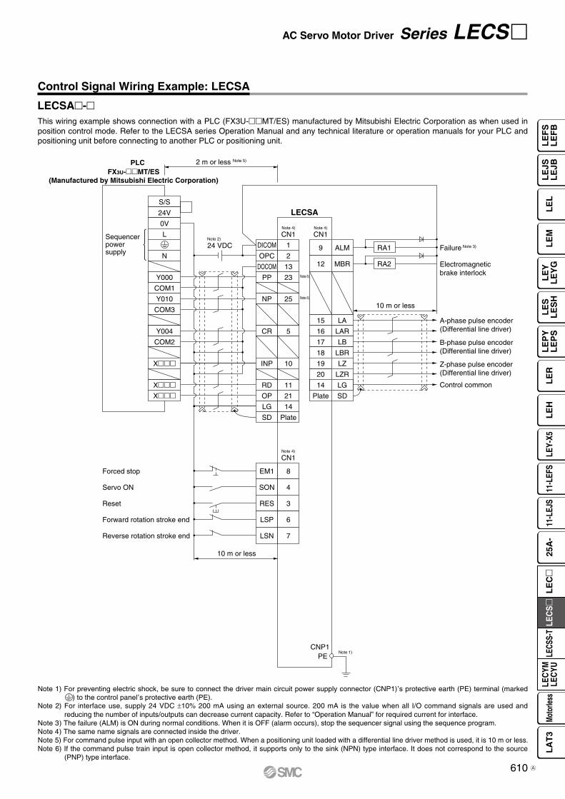
Control Signal Wiring Example: LECSA
Note 1) For preventing electric shock, be sure to connect the driver main circuit power supply connector (CNP1),s protective earth (PE) terminal (marked
) to the control panel,s protective earth (PE).
Note 2) For interface use, supply 24 VDC ±10% 200 mA using an external source. 200 mA is the value when all I/O command signals are used and reducing the number of inputs/outputs can decrease current capacity. Refer to “Operation Manual” for required current for interface.
Note 3) The failure (ALM) is ON during normal conditions. When it is OFF (alarm occurs), stop the sequencer signal using the sequence program.Note 4) The same name signals are connected inside the driver.Note 5) For command pulse input with an open collector method. When a positioning unit loaded with a differential line driver method is used, it is 10 m or less.Note 6) If the command pulse train input is open collector method, it supports only to the sink (NPN) type interface. It does not correspond to the source
(PNP) type interface.
This wiring example shows connection with a PLC (FX3U-MT/ES) manufactured by Mitsubishi Electric Corporation as when used in position control mode. Refer to the LECSA series Operation Manual and any technical literature or operation manuals for your PLC and positioning unit before connecting to another PLC or positioning unit.
LECSA-
AC Servo Motor Driver Series LECS
LECS-P09-CS3e.indd 9 15.10.8 5:26:05 PM
610
LE
FS
LE
FB
LE
LL
EJS
LE
JBL
EM
LE
YL
EY
GL
ES
LE
SH
LE
PY
LE
PS
LE
RL
EH
LEY-
X511
-LEF
S11
-LEJ
S25
A-
LEC
YMLE
CYU
LECS
S-T
LA
T3
Moto
rless
LEC
S
LE
C
A

Positioning unitQD75D (Manufactured by
Mitsubishi Electric Corporation)
PE
CLEARCOM
CLEAR
RDYCOM
READY
PULSE F+
PULSE F–
S/S
PG0
PG0 COM
LECSB
24 VDC Note 2)
CN1
DICOM
DOCOM
CR
PP
NG
LG
LZ
SD
Note 4)
Note 4)
CN1
CN1
CN6
2 m or less
10 m or less
10 m or less Note 5)
2 m or less
10 m or less
Note 1)
20
46
41
10
PG 11
NP 35
36
3
LZR 9
8
Plate
21
48
Plate
33
DICOM
EMGEmergency stop
Servo ON
Reset
Proportion control
External torque limit selection
Forward rotation stroke end
Reverse rotation stroke end
Analog torque limit+10 V/Maximum torque
Upper limit setting
42
SON 15
RES 19
PC 17
TL 18
LSP 43
LSN 44
DOCOM 47
P15R 1
TLA 27
LG 28
SD Plate
ALM
23 ZSP
25 TLC
24 INP
4 LA
5 LAR
6 LB
7 LBR
SD
OP
34 LG
1 P15R
Failure Note 3)
Zero speed detection
Torque limiting
Positioning completion
A-phase pulse encoder(Differential line driver)
B-phase pulse encoder(Differential line driver)
Z-phase pulse encoder(Open collector)
Control common
Control common
RA1
RA2
RA3
2 m or less
1 LG
3 MO1
2 MO2 Analog monitor 2
Analog monitor 1
±10 VDC
±10 VDC
RA4
PULSE R+
PULSE R–
14
13
12
11
15
16
10
9
17
18
RD 49
Note 4)
Note 4)
Note 6)
Note 6)
Control Signal Wiring Example: LECSB
Note 1) For preventing electric shock, be sure to connect the driver,s protective earth (PE) terminal (marked ) to the control panel
,s protective earth (PE).
Note 2) For interface use, supply 24 VDC ±10% 300 mA using an external source.Note 3) The failure (ALM) is ON during normal conditions. When it is OFF (alarm occurs), stop the sequencer signal using the sequence program.Note 4) The same name signals are connected inside the driver.Note 5) For command pulse input with a differential line driver method. For open collector method, it is 2 m or less.Note 6) If the command pulse train input is open collector method, it supports only to the sink (NPN) type interface. It does not correspond to the source
(PNP) type interface.
This wiring example shows connection with a positioning unit (QD75D) manufactured by Mitsubishi Electric Corporation as when used in position control mode. Refer to the LECSB series Operation Manual and any technical literature or operation manuals for your PLC and positioning unit before connecting to another PLC or positioning unit.
Series LECS
LECS-P10-CS3e.indd 10 15.10.8 5:28:26 PM
611A

PE
CN6
LECSC
CN6
10 m or less
10 m or less
Note 1)
14
15
Plate
25
RD
DICOM
Forced stop
Proximity dog
Forward rotation stroke end
Reverse rotation stroke end
5
DOCOM 17
EMG 1
DOG 2
LSP 3
LSN 4
ALM
16 ZP
13 LZ
26 LZR
11 LA
24 LAR
SD
LBR
12 LB
23 LG
Ready
Failure Note 3)
Return to origin completion
Z-phase pulse encoder(Differential line driver)
A-phase pulse encoder(Differential line driver)
B-phase pulse encoder(Differential line driver)
Control common
RA1
RA2
RA3
Note 2)
+24 VDC
−Powersupply
CN1
CC-Link
Control Signal Wiring Example: LECSC
Note 1) For preventing electric shock, be sure to connect the driver,s protective earth (PE) terminal (marked ) to the control panel
,s protective earth (PE).
Note 2) For interface use, supply 24 VDC ±10% 150 mA using an external source.Note 3) The failure (ALM) is ON during normal conditions. When it is OFF (alarm occurs), stop the sequencer signal using the sequence program.
AC Servo Motor Driver Series LECS
LECS-P11-CS3e.indd 11 14.1.31 8:13:39 PM
612
LE
FS
LE
FB
LE
LL
EJS
LE
JBL
EM
LE
YL
EY
GL
ES
LE
SH
LE
PY
LE
PS
LE
RL
EH
LEY-
X511
-LEF
S11
-LEJ
S25
A-
LEC
YMLE
CYU
LECS
S-T
LA
T3
Moto
rless
LEC
S
LE
C
PE
LECSS
LECSS
CN3CN3
10 m or less 10 m or less
Note 4) Note 4)
Note 7)
Note 7)
Note 7)
Note 7)
Note 6)
Note 6)
Note 6)
13
9
4
11
MBRDICOM
Forced stop
Upper stroke limit (FLS)
Lower stroke limit (RLS)
Proximity dog (DOG)
5
D0COM 3
EM1 20
D11 2
D12 12
D13 19
INP
15 ALM
10 DICOM
6 LA
16 LAR
7 LB
17 LBR
8 LZ
MO1
1 LG
14 MO2
Plate SD
LG
18 LZR
Electromagnetic brake interlock Note 2)
In position
Failure Note 3)
A-phase pulse encoder(Differential line driver)
SSCNET#optical cable Note 5)
(Option)
SSCNET#optical cable Note 5)
(Option)
Cap Note 8)
Servo systemcontroller
B-phase pulse encoder(Differential line driver)
Z-phase pulse encoder(Differential line driver)
Control common
Analog monitor 1
Analog monitor 2
SW1
SW2
(Axis 2)
1 2
SW1
SW2
1 2
RA2
RA3
2 m or less
CN1A
CN1B
CN1A
CN1B
CN1A
CN1B
CN1A
CN1B
RA1
LECSS(Axis 3)
SW1
SW2
1 2
LECSS(Axis n)
SW1
SW2
1 2
24 VDCNote 2)
Note 1)
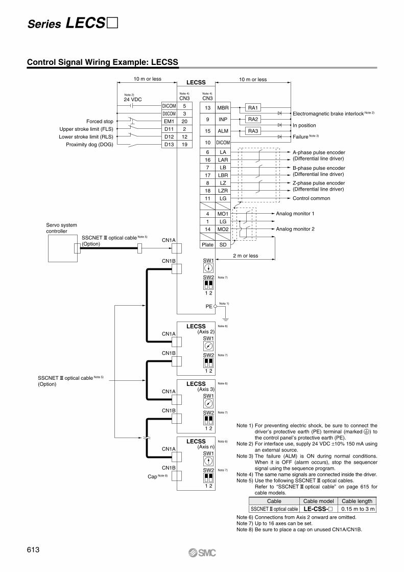
Control Signal Wiring Example: LECSS
Cable Cable model Cable lengthSSCNET#optical cable LE-CSS- 0.15 m to 3 m
Series LECS
Note 1) For preventing electric shock, be sure to connect the driver
,s protective earth (PE) terminal (marked ) to
the control panel,s protective earth (PE).
Note 2) For interface use, supply 24 VDC ±10% 150 mA using an external source.
Note 3) The failure (ALM) is ON during normal conditions. When it is OFF (alarm occurs), stop the sequencer signal using the sequence program.
Note 4) The same name signals are connected inside the driver.Note 5) Use the following SSCNET#optical cables. Refer to “SSCNET#optical cable” on page 615 for
cable models.
Note 6) Connections from Axis 2 onward are omitted.Note 7) Up to 16 axes can be set.Note 8) Be sure to place a cap on unused CN1A/CN1B.
LECS-P12-CS3e.indd 12 15.2.24 11:39:23 AM
613

(30) L
(13.
7)
L(29.6)
(11.
8)(1
3)
(30) L 37.4
18.8
39
37.2
52.4
39
33.3
39
Options
Motor cable, Lock cable, Encoder cable (LECS common)
Cable type
Cable description
Motor type
Cable length (L) [m]
LE CS M S 5 A
I/O connector (Without cable, Connector only)
LE-CSNA
Driver type
LE-CSNB LE-CSNSLE CSN A
* LE-CSNA: 10126-3000PE (connector)/10326-52F0-008 (shell kit) manufactured by Sumitomo 3M Limited or equivalent item. LE-CSNB: 10150-3000PE (connector)/10350-52F0-008 (shell kit) manufactured by Sumitomo 3M Limited or equivalent item. LE-CSNS: 10120-3000PE (connector)/10320-52F0-008 (shell kit) manufactured by Sumitomo 3M Limited or equivalent item.
* Applicable conductor size: AWG24 to 30
LE-CSM-: Motor cable
LE-CSB-: Lock cable
LE-CSE-: Encoder cable
Direction of connector
A
Axis side
B
Counter axis side
A LECSA, LECSCB LECSBS LECSS
2 2
5 5
A 10
S Standard cable
R Robotic cable
S AC servo motor
M Motor cable
B Lock cable
E Encoder cable
AC Servo Motor Driver Series LECS
LECS-P13-CS3e.indd 13 15.2.26 7:48:19 PM
614
LE
FS
LE
FB
LE
LL
EJS
LE
JBL
EM
LE
YL
EY
GL
ES
LE
SH
LE
PY
LE
PS
LE
RL
EH
LEY-
X511
-LEF
S11
-LEJ
S25
A-
LEC
YMLE
CYU
LECS
S-T
LA
T3
Moto
rless
LEC
S
LE
C

Name plate + Lot. No.
A side B side
UT
W
H
Pin 1
Pin no. n
1500
80100
PLC sideDriver side
90 15
øD
WiringLEC-CSNA-1: Pin no. 1 to 26LEC-CSNB-1: Pin no. 1 to 50LEC-CSNS-1: Pin no. 1 to 20
Connectorpin no.
Pair no. of wire
Insulationcolor Dot mark Dot
color
A s
ide
11 Orange
Red2 Black3
2 Light gray
Red4 Black5
3 WhiteRed
6 Black7
4 YellowRed
8 Black9
5 PinkRed
10 Black11
6 OrangeRed
12 Black13
7 Light gray
Red14 Black15
8 WhiteRed
16 Black17
9 YellowRed
18 Black
Connectorpin no.
Pair no. of wire
Insulationcolor Dot mark Dot
color
A s
ide
1910 Pink
Red20 Black21
11 OrangeRed
22 Black23
12 Light gray
Red24 Black25
13 WhiteRed
26 Black27
14 YellowRed
28 Black29
15 PinkRed
30 Black31
16 OrangeRed
32 Black33
17 Light gray
Red34 Black
Connectorpin no.
Pair no. of wire
Insulationcolor Dot mark Dot
color
A s
ide
3518 White
Red36 Black37
19 YellowRed
38 Black39
20 PinkRed
40 Black41
21 OrangeRed
42 Black43
22 Light gray
Red44 Black45
23 WhiteRed
46 Black47
24 YellowRed
48 Black49
25 PinkRed
50 Black
Options
1
∗ LEC-CSNA-1: 10126-3000PE (connector)/10326-52F0-008 (shell kit) manufactured by Sumitomo 3M Limited or equivalent item.LEC-CSNB-1: 10150-3000PE (connector)/10350-52F0-008 (shell kit) manufactured by Sumitomo 3M Limited or equivalent item.LEC-CSNS-1: 10120-3000PE (connector)/10320-52F0-008 (shell kit) manufactured by Sumitomo 3M Limited or equivalent item.
∗ Conductor size: AWG24
Dimensions/Pin No.Product no. W H T U Pin no. n
LEC-CSNA-139
37.212.7
14 14
LEC-CSNB-1 52.4 18 26
LEC-CSNS-1 33.3 14 21
Cable O.D.Product no. øD
LEC-CSNA-1 11.1
LEC-CSNB-1 13.8
LEC-CSNS-1 9.1
I/O cable
Driver typeA LECSA, LECSCB LECSBS LECSS
LEC CSN A1
∗ LE-CSS- is MR-J3BUSM manufactured by Mitsubishi Electric Corporation.
Cable lengthL 0.15 m
K 0.3 m
J 0.5 m
1 1 m
3 3 m
SSCNET#optical cable
LE CSS
Motor typeS AC servo motor
Cable descriptionS SSCNET#optical cable
Cable length (L) [m]1 1.5
AC Servo Motor Driver Series LECS
LECS-P13~1-web修正-CS3e.indd 1 16.1.7 4:13:54 PM
615
Series LECS
A

6
ø6 Mounting hole
(6)
156
168
6
30
15
1214
4(1
2)
5
1.6
(20)
119
99
(6)
ø6 Mounting hole40
36
15
168
156
66
149
5
144
12
(20)
169
2
Options
12
Regeneration option type032 Allowable regenerative power 30 W
12 Allowable regenerative power 100 W
∗ Confirm regeneration option to be used in “Model Selection”.
Regeneration option (LECSl common)
LEC MR RB
WeightModel Weight [kg]
LEC-MR-RB-032 0.5∗ MR-RB032 manufactured by Mitsubishi
Electric Corporation.
WeightModel Weight [kg]
LEC-MR-RB-12 1.1∗ MR-RB12 manufactured by Mitsubishi
Electric Corporation.
LEC-MR-RB-032 LEC-MR-RB-12
AC Servo Motor Driver Series LECS
LECS-P13~2-web修正-CS3e.indd 2 16.1.8 10:04:12 AM
615-1
LE
FS
LE
FB
LE
LL
EJS
LE
JBL
EM
LE
YL
EY
GL
ES
LE
SH
LE
PY
LE
PS
LE
RL
EH
LEY-
X511
-LEF
S11
-LEJ
S25
A-
LEC
YMLE
CYU
LECS
S-T
LA
T3
Moto
rless
LEC
S
LE
C
A


USB cable
PC Setup software(MR Configurator2™)
Compatible PC
Hardware Requirements
Setup Software Compatible Driver
When using setup software (MR Configurator2™), use an IBM PC/AT compatible PC that meets the following operating conditions.
Setup software (MR Configurator2™) (LECSA, LECSB, LECSC, LECSS common)
LEC MRC2* SW1DNC-MRC2- manufactured by Mitsubishi Electric Corporation.
Refer to Mitsubishi Electric Corporation’s website for operating environment and version upgrade information.MR Configurator2™ is a registered trademark or trademark of Mitsubishi Electric Corporation.
Display language
Adjustment, waveform display, diagnostics, parameter read/write, and test operation can be performed upon a PC.
Note 1) Before using a PC for setting LECSA point table method/program operation method, upgrade to version 1.18U (Japanese version)/version 1.19V (English version) or later. Refer to Mitsubishi Electric Corporation’s website for version upgrade information.
Note 2) Windows® and Windows Vista® are registered trademarks of Microsoft Corporation in the United States and other countries.
Note 3) On some PCs, setup software (MR Configurator2™) may not run properly.
Note 4) When Windows®XP or later is used, the following functions cannot be used.· Windows Program Compatibility mode· Fast User Switching· Remote Desktop· Large Fonts Mode (Display property)· DPI settings other than 96 DPI (Display property)· 64-bit OSs are not supported, except for
Microsoft® Windows®7 or later.Note 5) When Windows®7 is used, the following functions cannot be used.
· Windows XP Mode· Windows Touch
Note 6) When using this software with Windows Vista® or later, log in as a user having USER authority or higher.
Note 7) When Windows®8 is used, the following functions cannot be used.· Hyper-V· Modern UI style
Note 8) Order USB cable separately.· This cable is compatible with the setup software
(MR Configurator™: LEC-MR-SETUP221).Note 9) Using a PC for setting Windows®8.1, upgrade to
version 1.25B or later. Refer to Mitsubishi Electric Corporation’s website for version upgrade information.
EquipmentSetup software (MR Configurator2™)
LEC-MRC2
Note 1) 2) 3)
4) 5) 6) 7) 9)
PC
OS
Microsoft® Windows®8 Enterprise Operating SystemMicrosoft® Windows®8 Pro Operating SystemMicrosoft® Windows®8 Operating SystemMicrosoft® Windows®7 Enterprise Operating SystemMicrosoft® Windows®7 Ultimate Operating SystemMicrosoft® Windows®7 Professional Operating SystemMicrosoft® Windows®7 Home Premium Operating SystemMicrosoft® Windows®7 Starter Operating SystemMicrosoft® Windows Vista® Enterprise Operating SystemMicrosoft® Windows Vista® Ultimate Operating SystemMicrosoft® Windows Vista® Business Operating SystemMicrosoft® Windows Vista® Home Premium Operating SystemMicrosoft® Windows Vista® Home Basic Operating SystemMicrosoft® Windows®XP Professional Operating System, Service Pack 2 or laterMicrosoft® Windows®XP Home Edition Operating System, Service Pack 2 or laterMicrosoft® Windows®2000 Professional Operating System, Service Pack 4 or later
Available HD space
1 GB or more
Communication interface
Use USB port.
DisplayResolution 1024 x 768 or more
Must be capable of high color (16-bit) display.The connectable with the above PC
Keyboard The connectable with the above PCMouse The connectable with the above PCPrinter The connectable with the above PCUSB cable Note 8) LEC-MR-J3USB
Compatibledriver
Setup softwareMR Configurator™ MR Configurator2™
LEC-MR-SETUP221 LEC-MRC2LECSA v v
LECSB v v
LECSC v v
LECSS-S v v
LECSS2-T — v
Nil Japanese versionE English versionC Chinese version
Options
USB cable (3 m) Battery (only for LECSB, LECSC or LECSS)
LEC MR J3USB LEC MR J3BATCable for connecting PC and driver when using the setup software (MR Configurator2™).Do not use any cable other than this cable.
* MR-J3BAT manufactured by Mitsubishi Electric Corporation.* MR-J3USBCBL3M manufactured by Mitsubishi Electric Corporation.
DriversLECSA LECSB LECSC LECSS
Battery for replacement.Absolute position data is maintained by installing the battery to the driver.
Series LECS
LECS-P14-CS3e.indd 14 15.7.27 7:44:01 PM
616
AC Servo Motor Driver Series LECS
LE
FS
LE
FB
LE
LL
EJS
LE
JBL
EM
LE
YL
EY
GL
ES
LE
SH
LE
PY
LE
PS
LE
RL
EH
LEY-
X511
-LEF
S11
-LEJ
S25
A-
LEC
YMLE
CYU
LECS
S-T
LA
T3
Moto
rless
LEC
S
LE
C

1. Use the specified voltage.If the applied voltage is higher than the specified voltage, malfunction and damage to the driver may result. If the applied voltage is lower than the specified voltage, there is a possibility that the load cannot be moved due to internal voltage drop. Check the operating voltage prior to start. Also, confirm that the operating voltage does not drop below the specified voltage during operation.
2. Do not use the products outside the specifications.Otherwise, fire, malfunction or damage to the driver/actuator can result. Check the specifications before use.
3. Install an emergency stop circuit.Install an emergency stop outside the enclosure in easy reach to the operator so that the operator can stop the system operation immediately and intercept the power supply.
4. To prevent danger and damage due to a breakdown or malfunction of these products, which may occur at a certain probability, a backup system should be arranged in advance by using a multiple-layered structure or by making a fail-safe equipment design etc.
5. If there is a risk of fire or personal injury due to abnormal heat generation, sparking, smoke generated by the product, etc., cut off the power supply from this product and the system immediately.
6. The parameters of the driver are set to initial values.Please change parameters according to the specifica-tions of the customer’s equipment before use.Refer to the operation manual for details of parameters.
1. Never touch the inside of the driver and its peripheral devices.Otherwise, electric shock or failure can result.
2. Do not operate or set up this equipment with wet hands.Otherwise, electric shock can result.
3. Do not use a product that is damaged or missing any components.Electric shock, fire or injury can result.
4. Use only the specified combination between the electric actuator and driver.Otherwise, it may cause damage to the driver or to the other equipment.
5. Be careful not to touch, get caught or hit by the workpiece while the actuator is moving.An injury can result.
6. Do not connect the power supply or power up the product until it is confirmed that the workpiece can be moved safely within the area that can be reached by the workpiece.Otherwise, the movement of the workpiece may cause an accident.
7. Do not touch the product when it is energized and for some time after the power has been disconnected, as it is very hot.Otherwise, it may cause burns due to the high temperature.
8. Check the voltage using a tester at least 5 minutes after power-off when performing installation, wiring and maintenance.Otherwise, electric shock, fire or injury can result.
9. Static electricity may cause a malfunction or damage the driver. Do not touch the driver while power is supplied to it.Take sufficient safety measures to eliminate static electricity when it is necessary to touch the driver for maintenance.
10. Do not use the products in an area where they could be exposed to dust, metallic powder, machining chips or splashes of water, oil or chemicals.Otherwise, a failure or malfunction can result.
11. Do not use the products in a magnetic field.Otherwise, a malfunction or failure can result.
12. Do not use the products in an environment where flammable, explosive or corrosive gases, liquids or other substances are present.Otherwise, fire, explosion or corrosion can result.
13. Avoid heat radiation from strong heat sources, such as direct sunlight or a hot furnace.Otherwise, it will cause a failure to the driver or its peripheral devices.
14. Do not use the products in an environment with cyclic temperature changes.Otherwise, it will cause a failure to the driver or its peripheral devices.
15. Do not use the products in an environment where surges are generated.Devices (solenoid type lifters, high frequency induction furnaces, motors, etc.) that generate a large amount of surge around the product may lead to deterioration or damage to the internal circuits of the products. Avoid supplies of surge generation and crossed lines.
16. Do not install these products in a place subject to vibration and impact.Otherwise, a malfunction or failure can result.
17. When a surge generating load such as a relay or solenoid valve is directly driven, use a product that incorporates a surge absorption element.
Mounting
1. Install the driver and its peripheral devices on fireproof material.Direct installation on or near flammable material may cause fire.
2. Do not install these products in a place subject to vibration and impact.Otherwise, a malfunction or failure can result.
3. The driver should be mounted on a vertical wall in a vertical direction.Also, do not cover the driver’s suction/exhaust ports.
4. Install the driver and its peripheral devices on a flat surface.If the mounting surface is not flat or uneven, excessive force may be applied to the housing and other parts resulting in a malfunction.
Series LECSSpecific Product Precautions 1Be sure to read this before handling. Refer to the back cover for Safety Instructions. For Electric Actuator Precautions, refer to “Handling Precautions for SMC Products” and the Operation Manual on SMC website, http://www.smcworld.com
Warning
Warning
WarningDesign/Selection Handling
Handling
Warning
LECS-P15-CS3e.indd 15 15.2.24 3:31:30 PM
Be sure to read this before handling. Refer to page 906 for Safety Instructions. For Electric Actuator Precautions, refer to pages 907 to 912, or “Handling Precautions for SMC Products” and the Operation Manual on SMC website, http://www.smcworld.com
617

Driver
Control panel
PE terminal Actuator
1. Perform maintenance checks periodically.Confirm wiring and screws are not loose. Loose screws or wires may cause unexpected malfunction.
2. Conduct an appropriate functional inspection and test after completed maintenance.In case of any abnormalities (if the actuator does not move or the equipment does not operate properly etc.), stop the operation of the system. Otherwise, unexpected malfunction may occur and safety cannot be assured. Conduct a test of the emergency stop to confirm the safety of the equipment.
3. Do not disassemble, modify or repair the driver or its peripheral devices.
4. Do not put anything conductive or flammable inside the driver.Otherwise, fire can result.
5. Do not conduct an insulation resistance test or insulation withstand voltage test.
6. Reserve sufficient space for maintenance.Design the system so that it allows required space for maintenance.
1. Use a power supply with low noise between lines and between power and ground.In cases where noise is high, use an isolation transformer.
2. Take appropriate measures to prevent surges from lightning. Ground the surge absorber for lightning separately from the grounding of the driver and its peripheral devices.
1. The driver will be damaged if a commercial power supply (100V/200V) is added to the driver
,s servo motor
power (U, V, W). Be sure to check wiring such as wiring mistakes when the power supply is turned on.
2. Connect the ends of the U, V, W wires from the motor cable correctly to the phases (U, V, W) of the servo motor power. If these wires do not match up, it is unable to control the servo motor.
1. For grounding actuator, connect the copper wire of the actuator to the driver,s protective earth (PE) terminal and connect the copper wire of the driver to the earth via the control panel,s protective earth (PE) terminal.Do not connect them directly to the control panel,s protective earth (PE) terminal.
2. In the unlikely event that malfunction is caused by the ground, it may be disconnected.
Series LECSSpecific Product Precautions 2Be sure to read this before handling. Refer to the back cover for Safety Instructions. For Electric Actuator Precautions, refer to “Handling Precautions for SMC Products” and the Operation Manual on SMC website, http://www.smcworld.com
CautionPower Supply
WarningWiring
WarningGrounding
WarningMaintenance
LECS-P16-CS3e.indd 16 14.2.19 0:11:46 PM
Be sure to read this before handling. Refer to page 906 for Safety Instructions. For Electric Actuator Precautions, refer to pages 907 to 912, or “Handling Precautions for SMC Products” and the Operation Manual on SMC website, http://www.smcworld.com
618
LE
FS
LE
FB
LE
LL
EJS
LE
JBL
EM
LE
YL
EY
GL
ES
LE
SH
LE
PY
LE
PS
LE
RL
EH
LEY-
X511
-LEF
S11
-LEJ
S25
A-
LEC
YMLE
CYU
LECS
S-T
LA
T3
Moto
rless
LEC
S
LE
C

619

50
Optical communication
PLC
100 150
Series LECSS-S
Series LECSS-T
3 times faster
NewNew
¡Applicable Fieldbus protocol:¡Bidirectional communication speed: 3 times
(High-speed optical communication, max. bidirectional communication speed: 150 Mbps)
¡SSCNET#/H and SSCNET#products are compatible.
Communication speed: 50 Mbps
¡Improved noise resistance ¡STO (Safe Torque Off) safety function available¡Control encoder: Absolute 22-bit encoder (Resolution: 4194304 p/rev)
Power supply voltage (V)200 to 240 VAC
Motor capacity (W)100/200/400
Bidirectional communication speed
(Mbps)
Current model
LECSS-S LECSS-T
SSCNET#compatible products SSCNET#/H compatible products
SSCNET#/H compatible controllersSSCNET# compatible controllers
SSCNET#/H compatible products can be added to existing SSCNET#systems for system expansion.Reassembly of the system (new installation of master PLC) is not required.* Note that the communication speed is that of SSCNET# (50 Mbps). NewNew
620
Series LEFS Series LEFB
Ball screw driveSeries LEFS
Belt driveSeries LEFB
Belt driveSeries LEJB
Ball screw driveSeries LEJS
Series LEJS Series LEJB
Guide rod typeSeries LEYG
Guide rod type/In-line motor typeSeries LEYGD
Basic typeSeries LEY
In-line motor typeSeries LEYD
Series LEY Series LEYSeries LEYG Series LEYG
Slider Type High Rigidity Slider TypeCompatible Actuators
AC Servo Motor DriverSeries LECSS-T
Compatible
RoHS
Rod Type Guide Rod Type
SizeMax. work load
[kg]Stroke[mm]
25 5 Up to 2000
32 15 Up to 2500
40 25 Up to 3000
SizeMax. work load
[kg]Stroke[mm]
25 20 Up to 800
32 45 Up to 1000
40 60 Up to 1200
SizeMax. work load
[kg]Stroke[mm]
40 20 Up to 2000
63 30 Up to 3000
SizeMax. work load
[kg]Stroke[mm]
40 55 Up to 1200
63 85 Up to 1500
SizePushing force
[N]Stroke[mm]
25 485Up to 300
32 736
SizePushing force
[N]Stroke[mm]
25 485Up to 300
32 588
SizePushing force
[N]Stroke[mm]
25 485 Up to 400
32 736 Up to 500
63 1910 Up to 800
SizePushing force
[N]Stroke[mm]
25 485 Up to 400
32 588 Up to 500
63 3343 Up to 800
Page 635Page 627
Page 641
Pages 623, 624 Pages 625, 626L
EF
SL
EF
BL
EL
LE
JSL
EJB
LE
ML
EY
LE
YG
LE
SL
ES
HL
EP
YL
EP
SL
ER
LE
HLE
Y-X5
11-L
EFS
11-L
EJS
25A
-LE
CYM
LEC
YULE
CSS-
TL
AT
3Mo
torle
ssLE
CS
LE
C
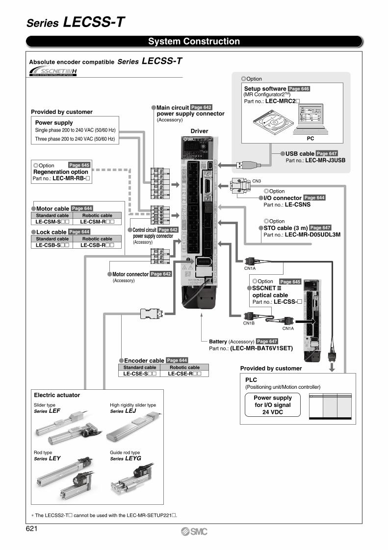
System Construction
Driver
Battery (Accessory)
PC
Setup software Page 646(MR Configurator2TM)Part no.: LEC-MRC2
Part no.: (LEC-MR-BAT6V1SET)
Provided by customer
Power supplySingle phase 200 to 240 VAC (50/60 Hz)
Three phase 200 to 240 VAC (50/60 Hz)
Provided by customer
Part no.: LEC-MR-RB-
OptionRegeneration option
Main circuitpower supply connector(Accessory)
Page 642
I/O connectorPart no.: LE-CSNS
USB cablePart no.: LEC-MR-J3USB
Page 647
Control circuitpower supply connector(Accessory)
Motor connector(Accessory)
Standard cable Robotic cableLE-CSM-S LE-CSM-R
Motor cable Page 644
Standard cable Robotic cableLE-CSB-S LE-CSB-R
Standard cable Robotic cableLE-CSE-S LE-CSE-R
Lock cable Page 644
Encoder cable Page 644
Page 642
Page 642
Power supplyfor I/O signal
24 VDC
PLC(Positioning unit/Motion controller)
Page 644
Page 645
Option
Option
Option
SSCNET#optical cablePart no.: LE-CSS-
Page 645
CN1ACN1B
CN1A
CN3
Page 647
Absolute encoder compatible Series LECSS-T
∗ The LECSS2-T cannot be used with the LEC-MR-SETUP221.
STO cable (3 m)Part no.: LEC-MR-D05UDL3M
OptionPage 647
Electric actuator
Rod typeSeries LEY
Guide rod typeSeries LEYG
High rigidity slider typeSeries LEJ
Slider typeSeries LEF
621
Series LECSS-T

INDEX
Compatible AC Servo Motor Driver
Electric Actuator/Guide Rod Type Series LEYG
How to Order ………………………………………………………………………………… Page 635Force Conversion Graph ……………………………………………………………… Page 637Specifications ………………………………………………………………………………… Page 638Dimensions …………………………………………………………………………………… Page 639
Electric Actuator/Slider Type, Belt DriveSeries LEFB
How to Order ………………………………………………………………………………… Page 624
Electric Actuator/High Rigidity Slider Type, Belt DriveSeries LEJB
How to Order ………………………………………………………………………………… Page 626
AC Servo Motor DriverSeries LECSS-T
How to Order ………………………………………………………………………………… Page 641Dimensions …………………………………………………………………………………… Page 641Specifications ………………………………………………………………………………… Page 642Power Supply Wiring Example ……………………………………………………… Page 642Control Signal Wiring Example ……………………………………………………… Page 643Options …………………………………………………………………………………………… Page 644
How to Order ………………………………………………………………………………… Page 623
How to Order ………………………………………………………………………………… Page 625
Electric Actuator/Slider Type, Ball Screw DriveSeries LEFS
Electric Actuator/High Rigidity Slider Type, Ball Screw DriveSeries LEJS
How to Order ………………………………………………………………………………… Page 627Force Conversion Graph ……………………………………………………………… Page 629Specifications ………………………………………………………………………………… Page 630Dimensions …………………………………………………………………………………… Page 632
Electric Actuator/Rod Type Series LEY
622
LE
FS
LE
FB
LE
LL
EJS
LE
JBL
EM
LE
YL
EY
GL
ES
LE
SH
LE
PY
LE
PS
LE
RL
EH
LEY-
X511
-LEF
S11
-LEJ
S25
A-
LEC
YMLE
CYU
LECS
S-T
LA
T3
Moto
rless
LEC
S
LE
C

How to Order
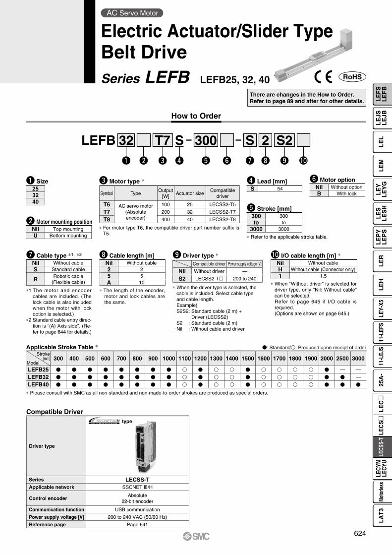
LEFS 32w
Hq
Re
T7r
200y
S2!0
Si
5o
Bt
Bu !1
Compatible Driver
Driver type
type
Series LECSS-TApplicable network SSCNET#/H
Control encoderAbsolute
22-bit encoder
Communication function USB communication
Power supply voltage [V] 200 to 240 VAC (50/60 Hz)
Reference page Page 641
There are changes in the How to Order. Refer to page 68 and after for other details.
Applicable Stroke Table *3 : Standard
50 100 150 200 250 300 350 400 450 500 550 600 650 700 750 800 850 900 950 1000 1100 1200
LEFS25 — — — — — —LEFS32 — —LEFS40 — —
*3 Please consult with SMC for non-standard strokes as they are produced as special orders.
Stroke[mm]Model
Please contact SMC for clean room specification and the models compatible with secondary batteries.
AC Servo Motor
Electric Actuator/Slider TypeBall Screw DriveSeries LEFS LEFS25, 32, 40
r Motor type *1
Symbol TypeOutput
[W]Actuator size
Compatible driver
T6 AC servo motor(Absolute encoder)
100 25 LECSS2-T5T7 200 32 LECSS2-T7T8 400 40 LECSS2-T8
*1 For motor type T6, the compatible driver part number suffix is T5.
e Motor mounting position
Nil In-lineR Right side parallelL Left side parallel
i Cable type *4, *6
Nil Without cableS Standard cableR Robotic cable (Flexible cable)
*4 The motor and encoder cables are included. (The lock cable is also included when the motor with lock option is selected.)
w Size253240
t Lead [mm]Symbol LEFS25 LEFS32 LEFS40
H 20 24 30A 12 16 20B 6 8 10
u Motor optionNil Without optionB With lock
y Stroke [mm] *2
50 50to to
1200 1200
*2 Refer to the applicable stroke table.
!0 Driver type *6
Compatible driver Power supply voltage [V]Nil Without driver —S2 LECSS2-T 200 to 240
*6 When the driver type is selected, the cable is included. Select cable type and cable length.Example)S2S2: Standard cable (2 m) +
Driver (LECSS2)S2 : Standard cable (2 m)Nil : Without cable and driver
o Cable length [m] *5, *6
Nil Without cable2 25 5A 10
*5 The length of the encoder, motor and lock cables are the same.
!1 I/O cable length [m] *7
Nil Without cableH Without cable (Connector only)1 1.5
*7 When “Without driver” is selected for driver type, only “Nil: Without cable” can be selected.Refer to page 645 if I/O cable is required.(Options are shown on page 645.)
q AccuracyNil Basic typeH High precision type
623
How to Order
e Motor type *
Symbol TypeOutput
[W]Actuator size
Compatible driver
T6 AC servo motor(Absolute encoder)
100 25 LECSS2-T5
T7 200 32 LECSS2-T7
T8 400 40 LECSS2-T8
* For motor type T6, the compatible driver part number suffix is T5.
o Driver type *Compatible driver Power supply voltage [V]
Nil Without driver —
S2 LECSS2-T 200 to 240
* When the driver type is selected, the cable is included. Select cable type and cable length.Example)S2S2: Standard cable (2 m) +
Driver (LECSS2)S2 : Standard cable (2 m)Nil : Without cable and driver
LEFB 32q w
T7e
300t
S2o
Su
2iy !0r
S
Compatible Driver
Driver type
type
Series LECSS-TApplicable network SSCNET#/H
Control encoderAbsolute
22-bit encoder
Communication function USB communication
Power supply voltage [V] 200 to 240 VAC (50/60 Hz)
Reference page Page 641
Applicable Stroke Table * : Standard/: Produced upon receipt of order
* Please consult with SMC as all non-standard and non-made-to-order strokes are produced as special orders.
300 400 500 600 700 800 900 1000 1100 1200 1300 1400 1500 1600 1700 1800 1900 2000 2500 3000
LEFB25 — —
LEFB32 —
LEFB40
Stroke[mm]
Model
w Motor mounting positionNil Top mountingU Bottom mounting
* The length of the encoder, motor and lock cables are the same.
i Cable length [m]Nil Without cable2 25 5A 10
*1 The motor and encoder cables are included. (The lock cable is also included when the motor with lock option is selected.)
*2 Standard cable entry direc-tion is “(A) Axis side”. (Re-fer to page 644 for details.)
u Cable type *1, *2
Nil Without cableS Standard cable
R Robotic cable (Flexible cable)
* Refer to the applicable stroke table.
t Stroke [mm]300 300to to
3000 3000
y Motor optionNil Without optionB With lock
r Lead [mm]S 54
q Size253240
!0 I/O cable length [m] *Nil Without cableH Without cable (Connector only)1 1.5
* When “Without driver” is selected for driver type, only “Nil: Without cable” can be selected.Refer to page 645 if I/O cable is required.(Options are shown on page 645.)
There are changes in the How to Order. Refer to page 89 and after for other details.
AC Servo Motor
Electric Actuator/Slider TypeBelt DriveSeries LEFB LEFB25, 32, 40
624
LE
FS
LE
FB
LE
LL
EJS
LE
JBL
EM
LE
YL
EY
GL
ES
LE
SH
LE
PY
LE
PS
LE
RL
EH
LEY-
X511
-LEF
S11
-LEJ
S25
A-
LEC
YMLE
CYU
LECS
S-T
LA
T3
Moto
rless
LEC
S
LE
C

How to Order
Applicable Stroke Table *3 : Standard
*3 Please consult with SMC for non-standard strokes as they are produced as special orders.
200 300 400 500 600 700 800 900 1000 1200 1500
LEJS40 —
LEJS63 —
Stroke[mm]
Model
o Driver type *6
Compatible driver Power supply voltage [V]
Nil Without driver —
S2 LECSS2-T 200 to 240
*6 When the driver type is selected, the cable is included. Select cable type and cable length.Example)S2S2: Standard cable (2 m) +
Driver (LECSS2)S2 : Standard cable (2 m)Nil : Without cable and driver
e Motor type *1
Symbol TypeOutput
[W]Actuator size
Compatible driver
T6 AC servo motor(Absolute encoder)
100 40 LECSS2-T5
T7 200 63 LECSS2-T7
*1 For motor type T6, the compatible driver part number suffix is T5.
u Cable type *4, *6
Nil Without cable
S Standard cable
R Robotic cable (Flexible cable)
*4 The motor and encoder cables are included. (The lock cable is also included when the motor with lock option is selected.)
w Size4063
r Lead [mm]Symbol LEJS40 LEJS63
H 24 30
A 16 20
B 8 10
i Cable length [m] *5, *6
Nil Without cable
2 2
5 5
A 10
*5 The length of the encoder, motor and lock cables are the same.
y Motor optionNil Without option
B With lock
t Stroke [mm] *2
200to
1500
*2 Refer to the applicable stroke table.
Compatible Driver
Driver type
type
Series LECSS-TApplicable network SSCNET#/H
Control encoderAbsolute
22-bit encoder
Communication function USB communication
Power supply voltage [V] 200 to 240 VAC (50/60 Hz)
Reference page Page 641
LEJS 40 500AHw e rq t y u i o !0
T6
q AccuracyNil Basic type
H High precision type
!0 I/O cable length [m] *7
Nil Without cableH Without cable (Connector only)1 1.5
*7 When “Without driver” is selected for driver type, only “Nil: Without cable” can be selected.Refer to page 645 if I/O cable is required.(Options are shown on page 645.)
There are changes in the How to Order. Refer to page 124 and after for other details.
AC Servo Motor
Electric Actuator/High Rigidity Slider TypeBall Screw DriveSeries LEJS LEJS40, 63
Please contact SMC for clean room specification and the models compatible with secondary batteries.
625

T
How to Order
LEJB 40 500q w e r t y u i o
Applicable Stroke Table *3 : Standard
*3 Please consult with SMC for non-standard strokes as they are produced as special orders.
T6
200 300 400 500 600 700 800 900 1000 1200 1500 2000 3000
LEJB40 —
LEJB63 —
Stroke[mm]
Model
i Driver type *6
Compatible driver Power supply voltage [V]
Nil Without driver —
S2 LECSS2-T 200 to 240
*6 When the driver type is selected, the cable is included. Select cable type and cable length.Example)S2S2: Standard cable (2 m) +
Driver (LECSS2)S2 : Standard cable (2 m)Nil : Without cable and driver
w Motor type *1
Symbol TypeOutput
[W]Actuator size
Compatible driver
T6 AC servo motor(Absolute encoder)
100 40 LECSS2-T5
T7 200 63 LECSS2-T7
*1 For motor type T6, the compatible driver part number suffix is T5.
y Cable type *4, *6
Nil Without cable
S Standard cable
R Robotic cable (Flexible cable)
*4 The motor and encoder cables are included. (The lock cable is also included when the motor with lock option is selected.)
q Size4063
e Lead [mm]Symbol LEJB40 LEJB63
T 27 42
u Cable length [m] *5, *6
Nil Without cable
2 2
5 5
A 10
*5 The length of the encoder, motor and lock cables are the same.
t Motor optionNil Without option
B With lock
r Stroke [mm] *2
200to
3000
*2 Refer to the applicable stroke table.
Compatible Driver
Driver type
type
Series LECSS-TApplicable network SSCNET#/H
Control encoderAbsolute
22-bit encoder
Communication function USB communication
Power supply voltage [V] 200 to 240 VAC (50/60 Hz)
Reference page Page 641
o I/O cable length [m] *7
Nil Without cableH Without cable (Connector only)1 1.5
*7 When “Without driver” is selected for driver type, only “Nil: Without cable” can be selected.Refer to page 645 if I/O cable is required.(Options are shown on page 645.)
There are changes in the How to Order. Refer to page 129 and after for other details.
AC Servo Motor
Electric Actuator/High Rigidity Slider TypeBelt DriveSeries LEJB LEJB40, 63
626
LE
FS
LE
FB
LE
LL
EJS
LE
JBL
EM
LE
YL
EY
GL
ES
LE
SH
LE
PY
LE
PS
LE
RL
EH
LEY-
X511
-LEF
S11
-LEJ
S25
A-
LEC
YMLE
CYU
LECS
S-T
LA
T3
Moto
rless
LEC
S
LE
C

Motor
How to Order
* For motor type T6, the compatible driver part number suffix is T5.
r Motor type *
Symbol TypeOutput
[W]Actuator size
Compatible driver
T6AC servo motor
(Absolute encoder)
100 25 LECSS2-T5
T7 200 32 LECSS2-T7
T8 400 63 LECSS2-T8
!0 Mounting *1
Symbol TypeMotor mounting position
Top/Parallel In-line
Nil Ends tapped/ *2Body bottom tapped
L Foot —
F Rod flange *2 *4
G Head flange *2 *5 —
D Double clevis *3 —
*1 Mounting bracket is shipped together, (but not assembled).*2 For horizontal cantilever mounting with the rod flange, head flange and ends
tapped, use the actuator within the following stroke range.· LEY25: 200 mm or less · LEY32: 100 mm or less · LEY63: 400 mm or less
*3 For mounting with the double clevis, use the actuator within the following stroke range.· LEY25: 200 mm or less · LEY32: 200 mm or less · LEY63: 300 mm or less
*4 Rod flange is not available for the LEY25 with strokes 30 mm and motor option “With lock”.
*5 Head flange is not available for the LEY32/63.
t Lead [mm]Symbol LEY25 LEY32 *1 LEY63
A 12 16 (20) 20
B 6 8 (10) 10
C 3 4 (5) 5
L — — 2.86 *2
*1 The values shown in ( ) are the lead for top mounting, right/left side parallel types. (Equivalent lead which includes the pulley ratio [1.25:1])
*2 Only available for top mounting and right/left side parallel types. (Equivalent lead which includes the pulley ratio [4:7])
e Motor mounting position
Nil Top mounting
R Right side parallel
L Left side parallel
D In-line
o Rod end threadNil Rod end female thread
M Rod end male thread(1 rod end nut is included.)
i Motor optionNil Without option
B With lock
* When “With lock” is selected for the top mounting and right/left side parallel types, the motor body will stick out of the end of the body for size 25 with strokes 30 mm or less. Check for interference with workpieces before selecting a model.
y Stroke [mm]30 30
to to
800 800
* Refer to the applicable stroke table.
Applicable Stroke Table : Standard
30 50 100 150 200 250 300 350 400 450 500 600 700 800 Manufacturable stroke range
LEY25 — — — — — 15 to 400
LEY32 — — — 20 to 500
LEY63 — — — — — — 50 to 800
* Please consult with SMC for non-standard strokes as they are produced as special orders.
Stroke[mm]
Model
w Size253263
u Dust-tight/Water-jet-proof (Only available for LEY63)Symbol LEY25/32 LEY63
Nil IP4x equivalent IP5x equivalent (Dust-protected)
P —IP65 equivalent (Dust-tight/
Water-jet-proof)/With vent hole tap
* When using the dust-tight/water-jet-proof (IP65 equivalent), correctly mount the fitting and tubing to the vent hole tap, and then place the end of the tubing in an area not exposed to dust or water.
* The fitting and tubing should be provided separately by the customer. Select [Applicable tubing O.D.: ø4 or more, Connection thread: Rc1/8].
* Cannot be used in environments exposed to cutting oil etc. Take suitable protective measures.
LEY 25 200BH 2 S2Sw e r tq y u i o !0 !1 !2 !3 !4
T6
q AccuracyNil Basic type
H High precision type
There are changes in the How to Order, force conver-sion graph, specifications, weight and dimensions. Refer to page 248 and after for other details.
Please contact SMC for dust-tight/water-jet-proof (IP65 equivalent) and the models compatible with secondary batteries.
AC Servo Motor
Electric Actuator/Rod TypeSeries LEY LEY25, 32, 63
627

628
Electric Actuator/Rod Type Series LEYAC Servo Motor
Motor mounting position: Top/Parallel Motor mounting position: In-line
!3 Driver typeCompatible driver Power supply voltage [V]
Nil Without driver —
S2 LECSS2-T 200 to 240
* When the driver type is selected, the cable is included. Select cable type and cable length.Example)S2S2: Standard cable (2 m) + Driver (LECSS2)S2 : Standard cable (2 m)Nil : Without cable and driver
!2 Cable length [m] *Nil Without cable
2 2
5 5
A 10
* The length of the encoder, motor and lock cables are the same.
!1 Cable type *Nil Without cable
S Standard cable
R Robotic cable (Flexible cable)
* The motor and encoder cables are included. (The lock cable is also included when the motor with lock option is selected.)
* Standard cable entry direction is • Top/Parallel: (A) Axis side • In-line: (B) Counter axis side (Refer to page 614 for details.)
Compatible Driver
Driver type
type
Series LECSS-TApplicable network SSCNET#/H
Control encoderAbsolute
22-bit encoder
Communication function USB communication
Power supply voltage [V] 200 to 240 VAC (50/60 Hz)
Reference page Page 641
!4 I/O cable length [m] *Nil Without cable
H Without cable (Connector only)
1 1.5
* When “Without driver” is selected for driver type, only “Nil: Without cable” can be selected.Refer to page 645 if I/O cable is required.(Options are shown on page 645.)
LE
FS
LE
FB
LE
LL
EJS
LE
JBL
EM
LE
YL
EY
GL
ES
LE
SH
LE
PY
LE
PS
LE
RL
EH
LEY-
X511
-LEF
S11
-LEJ
S25
A-
LEC
YMLE
CYU
LECS
S-T
LA
T3
Moto
rless
LEC
S
LE
C
A
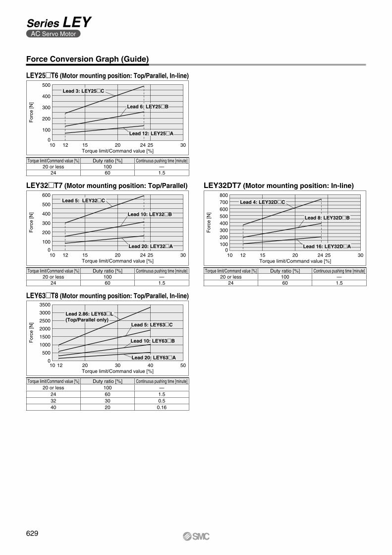
Force Conversion Graph (Guide)
LEY25T6 (Motor mounting position: Top/Parallel, In-line)
LEY32DT7 (Motor mounting position: In-line)LEY32T7 (Motor mounting position: Top/Parallel)
LEY63T8 (Motor mounting position: Top/Parallel, In-line)
Torque limit/Command value [%] Duty ratio [%] Continuous pushing time [minute]20 or less 100 —
24 60 1.5
Torque limit/Command value [%] Duty ratio [%] Continuous pushing time [minute]20 or less 100 —
24 60 1.5
Torque limit/Command value [%] Duty ratio [%] Continuous pushing time [minute]20 or less 100 —
24 60 1.5
Torque limit/Command value [%] Duty ratio [%] Continuous pushing time [minute]20 or less 100 —
24 60 1.532 30 0.540 20 0.16
For
ce [N
]
Torque limit/Command value [%]
500
400
300
200
100
020 25241510 12 30
Lead 3: LEY25C
Lead 6: LEY25B
Lead 12: LEY25A
For
ce [N
]
Torque limit/Command value [%]
600
500
400
300
200
100
02010 1512 302524
Lead 5: LEY32C
Lead 10: LEY32B
Lead 20: LEY32A
10 12 20 30 40 50Torque limit/Command value [%]
For
ce [N
]
3500
3000
2500
2000
1500
1000
500
0
Lead 5: LEY63C
Lead 2.86: LEY63L(Top/Parallel only)
Lead 10: LEY63B
Lead 20: LEY63A
For
ce [N
]
Torque limit/Command value [%]
800700600500400300200100
020 252410 1512 30
Lead 4: LEY32DC
Lead 8: LEY32DB
Lead 16: LEY32DA
629
Series LEYAC Servo Motor

Model LEY25 (Top/Parallel)/LEY25D (In-line) LEY32 (Top/Parallel) LEY32D (In-line)
Act
uat
or
spec
ifica
tio
ns
Stroke [mm] Note 1) 30, 50, 100, 150, 200, 250,300, 350, 400
30, 50, 100, 150, 200, 250,300, 350, 400, 450, 500
30, 50, 100, 150, 200, 250,300, 350, 400, 450, 500
Work load [kg]Horizontal Note 2) 18 50 50 30 60 60 30 60 60Vertical 8 16 30 9 19 37 12 24 46
Force [N] Note 3) (Set value: 12 to 24%) 65 to 131 127 to 255 242 to 485 79 to 157 154 to 308 294 to 588 98 to 197 192 to 385 368 to 736Max.Note 4)
speed[mm/s]
Strokerange
Up to 300 900 450 2251200 600 300 1000 500 250
305 to 400 600 300 150405 to 500 — — — 800 400 200 640 320 160
Pushing speed [mm/s] Note 5) 35 or less 30 or less 30 or lessMax. acceleration/deceleration [mm/s2] 5000 5000Positioning repeatability [mm]
Basic type ±0.02 ±0.02High precision type ±0.01 ±0.01
Lost motion Note 6) [mm]
Basic type 0.1 or lessHigh precision type 0.05 or less
Lead [mm] (including pulley ratio) 12 6 3 20 10 5 16 8 4Impact/Vibration resistance [m/s2] Note 7) 50/20 50/20Actuation type Ball screw + Belt (LEY)/Ball screw (LEYD) Ball screw + Belt [1.25:1] Ball screwGuide type Sliding bushing (Piston rod) Sliding bushing (Piston rod)Operating temperature range [°C] 5 to 40 5 to 40Operating humidity range [%RH] 90 or less (No condensation) 90 or less (No condensation)Required conditions for Note 8)
“Regeneration option” [kg]Horizontal 8 or more 31 or more Not required 15 or more Not required Not required 23 or more Not required Not requiredVertical 3 or more 2 or more 2 or more 6 or more 7 or more 11 or more 6 or more 7 or more 12 or more
Elec
tric
spe
cific
atio
ns Motor output/Size 100 W/40 200 W/60Motor type AC servo motor (200 VAC) AC servo motor (200 VAC)Encoder Motor type T6, T7: Absolute 22-bit encoder (Resolution: 4194304 p/rev)Powerconsumption [W] Note 9)
Horizontal 45 65 65Vertical 145 175 175
Standby power consumptionwhen operating [W] Note 10)
Horizontal 2 2 2Vertical 8 8 8
Max. instantaneous power consumption [W] Note 11) 445 724 724
Lock
uni
tsp
ecifi
catio
ns Type Note 12) Non-magnetizing lockHolding force [N] 131 255 485 157 308 588 197 385 736Power consumption [W] at 20°C Note 13) 6.3 7.9 7.9Rated voltage [V] 24 VDC 0
−10%
Size 25 32Lock Absolute encoder 0.3 0.4
Rod end male threadMale thread 0.03 0.03Nut 0.02 0.02
Foot (2 sets including mounting bolt) 0.08 0.14Rod flange (including mounting bolt)
0.17 0.20Head flange (including mounting bolt)Double clevis (including pin, retaining ring and mounting bolt) 0.16 0.22
Specifications
[kg]
[kg]Additional Weight
WeightProduct Weight
Series LEY25 (Motor mounting position: Top/Parallel) LEY32 (Motor mounting position: Top/Parallel)Stroke [mm] 30 50 100 150 200 250 300 350 400 30 50 100 150 200 250 300 350 400 450 500
Moto
r ty
pe Absolute encoder 1.4 1.5 1.6 1.9 2.0 2.2 2.4 2.6 2.7 2.3 2.4 2.7 3.2 3.5 3.8 4.1 4.3 4.6 4.9 5.2
Series LEY25D (Motor mounting position: In-line) LEY32D (Motor mounting position: In-line)Stroke [mm] 30 50 100 150 200 250 300 350 400 30 50 100 150 200 250 300 350 400 450 500
Moto
r ty
pe Absolute encoder 1.4 1.5 1.6 1.9 2.1 2.2 2.4 2.6 2.8 2.4 2.5 2.8 3.2 3.5 3.8 4.1 4.4 4.6 4.9 5.2
Note 1) Please consult with SMC for non-standard strokes as they are produced as special orders.Note 2) The maximum value of the horizontal work load. An external guide is necessary to
support the load. The actual work load changes according to the condition of the external guide. Please confirm using actual device.
Note 3) The force setting range (set values for the driver) for the force control with the torque control mode. Set it with reference to “Force Conversion Graph (Guide)” on page 629. When the control equivalent to the pushing operation of the controller LECP series is performed, combine the Simple Motion (manufactured by Mitsubishi Electric Corporation) which has a pushing operation function.
Note 4) The allowable speed changes according to the stroke.Note 5) The allowable collision speed for collision with the workpiece with the torque control
mode.Note 6) A reference value for correcting an error in reciprocal operation.Note 7) Impact resistance: No malfunction occurred when the actuator was tested with a drop
tester in both an axial direction and a perpendicular direction to the lead screw. (Test was
performed with the actuator in the initial state.)Vibration resistance: No malfunction occurred in a test ranging between 45 to 2000 Hz. Test was performed in both an axial direction and a perpendicular direction to the lead screw. (Test was performed with the actuator in the initial state.)
Note 8) The work load conditions which require “Regeneration option” when operating at the maximum speed (Duty ratio: 100%). Order the regeneration option separately. For details and order numbers, refer to “Required Conditions for Regeneration Option” on pages 225 and 226.
Note 9) The power consumption (including the driver) is for when the actuator is operating.Note 10) The standby power consumption when operating (including the driver) is for when the
actuator is stopped in the set position during the operation.Note 11) The maximum instantaneous power consumption (including the driver) is for when the
actuator is operating.Note 12) Only when motor option “With lock” is selected.Note 13) For an actuator with lock, add the power consumption for the lock.
630
Electric Actuator/Rod Type Series LEYAC Servo Motor
LE
FS
LE
FB
LE
LL
EJS
LE
JBL
EM
LE
YL
EY
GL
ES
LE
SH
LE
PY
LE
PS
LE
RL
EH
LEY-
X511
-LEF
S11
-LEJ
S25
A-
LEC
YMLE
CYU
LECS
S-T
LA
T3
Moto
rless
LEC
S
LE
C
A
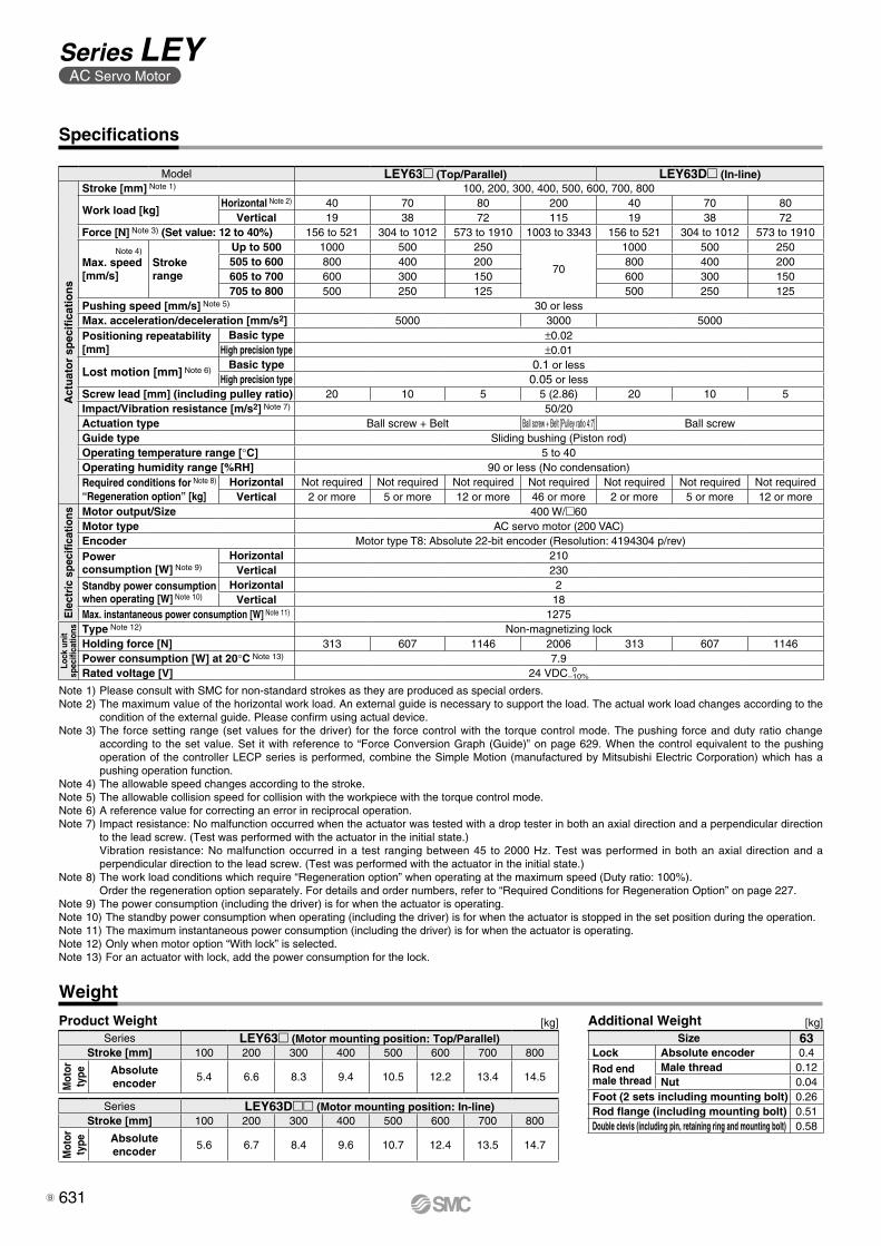
Product Weight Additional Weight[kg] [kg]
Specifications
Weight
Note 1) Please consult with SMC for non-standard strokes as they are produced as special orders.Note 2) The maximum value of the horizontal work load. An external guide is necessary to support the load. The actual work load changes according to the
condition of the external guide. Please confirm using actual device.Note 3) The force setting range (set values for the driver) for the force control with the torque control mode. The pushing force and duty ratio change
according to the set value. Set it with reference to “Force Conversion Graph (Guide)” on page 629. When the control equivalent to the pushing operation of the controller LECP series is performed, combine the Simple Motion (manufactured by Mitsubishi Electric Corporation) which has a pushing operation function.
Note 4) The allowable speed changes according to the stroke.Note 5) The allowable collision speed for collision with the workpiece with the torque control mode.Note 6) A reference value for correcting an error in reciprocal operation.Note 7) Impact resistance: No malfunction occurred when the actuator was tested with a drop tester in both an axial direction and a perpendicular direction
to the lead screw. (Test was performed with the actuator in the initial state.)Vibration resistance: No malfunction occurred in a test ranging between 45 to 2000 Hz. Test was performed in both an axial direction and a perpendicular direction to the lead screw. (Test was performed with the actuator in the initial state.)
Note 8) The work load conditions which require “Regeneration option” when operating at the maximum speed (Duty ratio: 100%).Order the regeneration option separately. For details and order numbers, refer to “Required Conditions for Regeneration Option” on page 227.
Note 9) The power consumption (including the driver) is for when the actuator is operating.Note 10) The standby power consumption when operating (including the driver) is for when the actuator is stopped in the set position during the operation.Note 11) The maximum instantaneous power consumption (including the driver) is for when the actuator is operating.Note 12) Only when motor option “With lock” is selected.Note 13) For an actuator with lock, add the power consumption for the lock.
Model LEY63 (Top/Parallel) LEY63D (In-line)
Act
uat
or
spec
ifica
tio
ns
Stroke [mm] Note 1) 100, 200, 300, 400, 500, 600, 700, 800
Work load [kg]Horizontal Note 2) 40 70 80 200 40 70 80
Vertical 19 38 72 115 19 38 72Force [N] Note 3) (Set value: 12 to 40%) 156 to 521 304 to 1012 573 to 1910 1003 to 3343 156 to 521 304 to 1012 573 to 1910
Note 4)
Max. speed[mm/s]
Stroke range
Up to 500 1000 500 250
70
1000 500 250505 to 600 800 400 200 800 400 200605 to 700 600 300 150 600 300 150705 to 800 500 250 125 500 250 125
Pushing speed [mm/s] Note 5) 30 or lessMax. acceleration/deceleration [mm/s2] 5000 3000 5000Positioning repeatability [mm]
Basic type ±0.02High precision type ±0.01
Lost motion [mm] Note 6) Basic type 0.1 or lessHigh precision type 0.05 or less
Screw lead [mm] (including pulley ratio) 20 10 5 5 (2.86) 20 10 5Impact/Vibration resistance [m/s2] Note 7) 50/20Actuation type Ball screw + Belt Ball screw + Belt [Pulley ratio 4:7] Ball screw Guide type Sliding bushing (Piston rod)Operating temperature range [°C] 5 to 40Operating humidity range [%RH] 90 or less (No condensation)Required conditions for Note 8)
“Regeneration option” [kg]Horizontal Not required Not required Not required Not required Not required Not required Not required
Vertical 2 or more 5 or more 12 or more 46 or more 2 or more 5 or more 12 or more
Ele
ctri
c sp
ecifi
catio
ns Motor output/Size 400 W/60Motor type AC servo motor (200 VAC)Encoder Motor type T8: Absolute 22-bit encoder (Resolution: 4194304 p/rev)Power consumption [W] Note 9)
Horizontal 210Vertical 230
Standby power consumption when operating [W] Note 10)
Horizontal 2Vertical 18
Max. instantaneous power consumption [W] Note 11) 1275
Lock
uni
tsp
ecifi
catio
ns Type Note 12) Non-magnetizing lockHolding force [N] 313 607 1146 2006 313 607 1146Power consumption [W] at 20°C Note 13) 7.9Rated voltage [V] 24 VDC 0
−10%
Size 63Lock Absolute encoder 0.4
Rod end male thread
Male thread 0.12Nut 0.04
Foot (2 sets including mounting bolt) 0.26Rod flange (including mounting bolt) 0.51Double clevis (including pin, retaining ring and mounting bolt) 0.58
Series LEY63 (Motor mounting position: Top/Parallel)Stroke [mm] 100 200 300 400 500 600 700 800
Mot
or
type Absolute
encoder5.4 6.6 8.3 9.4 10.5 12.2 13.4 14.5
Series LEY63D (Motor mounting position: In-line)Stroke [mm] 100 200 300 400 500 600 700 800
Mot
or
type Absolute
encoder5.6 6.7 8.4 9.6 10.7 12.4 13.5 14.7
631
Series LEYAC Servo Motor
B

Rod operating range Note 1)
(Stroke + G mm)
Encoder Z-phase detecting position
M
F±1
V
EV
J
K Note 2)
EHM
W
MY UM
TZ
S
X
L
Hthread depth C
B + Stroke
A + Stroke
4 x O1
thread depth RøD
4 x O1
thread depth R
ZZ
MH
(MB)ML + StrokeMAMC
MD
øXA H9 depth XA 6 x MO thread depth MR
Section XX
XA H9
XB
XARc 1/8Vent hole tap∗
18
Dimensions: Motor Top/Parallel
[mm]
Note 1) Range within which the rod can move. Make sure a workpiece mounted on the rod does not interfere with the workpieces and facilities around the rod.
Note 2) The direction of rod end width across flats (mK) differs depending on the products.
SizeStroke range
[mm]Without lock With lock
W X Z W X Z
2515 to 100
82.4 115.4 14.1 123 156 15.8105 to 400
3220 to 100
76.6 116.6 17.1 113.4 153.4 17.1105 to 500
63Up to 200
98.3 138.315.6
(16.6)135.1 175.1
15.6(16.6)
205 to 500505 to 800
SizeStroke range
[mm] A B C D EH EV F G H J K L M O1 R S T U Y V
2515 to 100 130.5 116
13 20 44 45.5 2 4 M8 x 1.25 24 17 14.5 34 M5 x 0.8 8 46 92 1 26.5 40105 to 400 155.5 141
3220 to 100 148.5 130
13 25 51 56.5 2 4 M8 x 1.25 31 22 18.5 40 M6 x 1.0 10 60 118 1 34 60105 to 500 178.5 160
63Up to 200 192.6 155.2
21 40 76 82 4 8 M16 x 2 44 36 37.4 60 M8 x 1.25 16 80 146 4 32.2 60205 to 500 227.6 190.2505 to 800 262.6 225.2
IP65 equivalent (Dust-tight/Water-jet-proof): LEY63mmm-mP(View ZZ)
* When using the dust-tight/water-jet-proof (IP65 equiva-lent), correctly mount the fitting and tubing to the vent hole tap, and then place the end of the tubing in an area not exposed to dust or water. The fitting and tubing should be provided separately by the customer.Select [Applicable tubing O.D.: ø4 or more, Connection thread: Rc1/8].
Section XX details
Body Bottom Tapped [mm]
SizeStroke range
[mm] MA MB MC MD MH ML MO MR XA XB
25
15 to 35
20 46
24 32
29
50
M5 x 0.8 6.5 4 540 to 100
42 41105 to 120
75125 to 200 59 49.5205 to 400 76 58
32
20 to 35
25 55
22 36
30
50
M6 x 1 8.5 5 640 to 100
36 43105 to 120
80125 to 200 53 51.5205 to 500 70 60
63
50 to 70
38 52.2
24 50
44 65
M8 x 1.25 10 6 775 to 120 45 60.5125 to 200 58 67205 to 500
86 81100
505 to 800 135
632
Electric Actuator/Rod Type Series LEYAC Servo Motor
LE
FS
LE
FB
LE
LL
EJS
LE
JBL
EM
LE
YL
EY
GL
ES
LE
SH
LE
PY
LE
PS
LE
RL
EH
LEY-
X511
-LEF
S11
-LEJ
S25
A-
LEC
YMLE
CYU
LECS
S-T
LA
T3
Moto
rless
LEC
S
LE
C
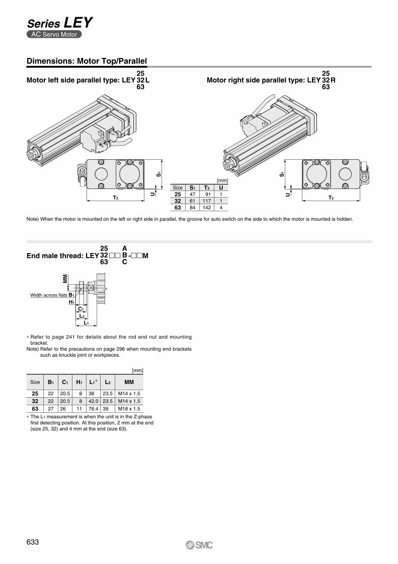
US
1
T2 T2
US
1
C1
L2
H1
MM
L1
Width across flats B1
Dimensions: Motor Top/Parallel
Motor left side parallel type: LEY L253263
Motor right side parallel type: LEY R253263
[mm]
Note) When the motor is mounted on the left or right side in parallel, the groove for auto switch on the side to which the motor is mounted is hidden.
Size S1 T2 U25 47 91 132 61 117 163 84 142 4
End male thread: LEY mm -mmM253263
ABC
* Refer to page 241 for details about the rod end nut and mounting bracket.
Note) Refer to the precautions on page 296 when mounting end brackets such as knuckle joint or workpieces.
[mm]
Size B1 C1 H1 L1* L2 MM
25 22 20.5 8 38 23.5 M14 x 1.5
32 22 20.5 8 42.0 23.5 M14 x 1.5
63 27 26 11 76.4 39 M18 x 1.5
* The L1 measurement is when the unit is in the Z-phase first detecting position. At this position, 2 mm at the end (size 25, 32) and 4 mm at the end (size 63).
633
Series LEYAC Servo Motor

10.5
50
Rc 1/8Vent hole tap∗
L
øD
B + Stroke
A + Stroke
W
Encoder Z-phase detecting position
Rod operating range Note 1)
(Stroke + G mm)
J
T EV
SEHM
K Note 2)
M
4 x O1
thread depth R
Hthread depth C
Z
V
U
F±1
ZZ
ML+ StrokeMAMC
MD Section XX
MH
øXA H9 depth XA 6 x MOthread depth MR
XA H9
XB
XA
Dimensions: In-line Motor
[mm]
Note 1) Range within which the rod can move. Make sure a workpiece mounted on the rod does not interfere with the workpieces and facilities around the rod.
Note 2) The direction of rod end width across flats (mK) differs depending on the products.
SizeStroke range
[mm] C D EH EV F G H J K L M O1 R S T U B V
2515 to 100
13 20 44 45.5 2 4 M8 x 1.25 24 17 14.5 34 M5 x 0.8 8 45 46.5 1.5136.5
40105 to 400 161.5
3220 to 100
13 25 51 56.5 2 4 M8 x 1.25 31 22 18.5 40 M6 x 1.0 10 60 61 1156
60105 to 500 186
63Up to 200
21 40 76 82 4 8 M16 x 2 44 36 37.4 60 M8 x 1.25 16 78 83 5190.7
60205 to 500 225.7505 to 800 260.7
SizeStroke range
[mm]Without lock With lock
A W Z A W Z
2515 to 100 233.4
82.4 14.6274
123 16.3105 to 400 258.4 299
3220 to 100 251.1
76.6 17.1287.9
113.4 17.1105 to 500 281.1 317.9
63Up to 200 326.4
98.3 8.1363.2
135.1 8.1205 to 500 361.4 398.2505 to 800 396.4 433.2
IP65 equivalent (Dust-tight/Water-jet-proof): LEY63Dmm-mP
* When using the dust-tight/water-jet-proof (IP65 equivalent), correctly mount the fitting and tubing to the vent hole tap, and then place the end of the tubing in an area not exposed to dust or water. The fitting and tubing should be provided separately by the customer.Select [Applicable tubing O.D.: ø4 or more, Connection thread: Rc1/8].
(View ZZ)
Body Bottom Tapped [mm]
SizeStroke range
[mm] MA MC MD MH ML MO MR XA XB
25
15 to 35
20
24 32
29
50
M5 x 0.8 6.5 4 540 to 100
42 41105 to 120
75125 to 200 59 49.5205 to 400 76 58
32
20 to 35
25
22 36
30
50
M6 x 1 8.5 5 640 to 100
36 43105 to 120
80125 to 200 53 51.5205 to 500 70 60
63
50 to 70
38
24 50
44 65
M8 x 1.25 10 6 775 to 120 45 60.5125 to 200 58 67205 to 500
86 81100
505 to 800 135
Section XX details
634
Electric Actuator/Rod Type Series LEYAC Servo Motor
LE
FS
LE
FB
LE
LL
EJS
LE
JBL
EM
LE
YL
EY
GL
ES
LE
SH
LE
PY
LE
PS
LE
RL
EH
LEY-
X511
-LEF
S11
-LEJ
S25
A-
LEC
YMLE
CYU
LECS
S-T
LA
T3
Moto
rless
LEC
S
LE
C
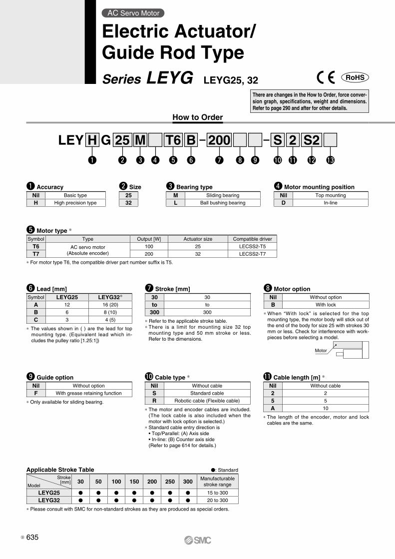
Motor
t Motor type *Symbol Type Output [W] Actuator size Compatible driver
T6 AC servo motor(Absolute encoder)
100 25 LECSS2-T5
T7 200 32 LECSS2-T7
y Lead [mm]Symbol LEYG25 LEYG32*
A 12 16 (20)
B 6 8 (10)
C 3 4 (5)
* The values shown in ( ) are the lead for top mounting type. (Equivalent lead which in-cludes the pulley ratio [1.25:1])
e Bearing typeM Sliding bearing
L Ball bushing bearing
r Motor mounting positionNil Top mounting
D In-line
u Stroke [mm]30 30
to to
300 300
* Refer to the applicable stroke table.* There is a limit for mounting size 32 top
mounting type and 50 mm stroke or less. Refer to the dimensions.
w Size2532
i Motor optionNil Without option
B With lock
* When “With lock” is selected for the top mounting type, the motor body will stick out of the end of the body for size 25 with strokes 30 mm or less. Check for interference with work-pieces before selecting a model.
!1 Cable length [m] *Nil Without cable
2 2
5 5
A 10
* The length of the encoder, motor and lock cables are the same.
o Guide optionNil Without option
F With grease retaining function
* Only available for sliding bearing.
!0 Cable type *Nil Without cable
S Standard cable
R Robotic cable (Flexible cable)
* The motor and encoder cables are included. (The lock cable is also included when the motor with lock option is selected.)
* Standard cable entry direction is • Top/Parallel: (A) Axis side • In-line: (B) Counter axis side (Refer to page 614 for details.)
Applicable Stroke Table V: Standard
30 50 100 150 200 250 300 Manufacturable stroke range
LEYG25 V V V V V V V 15 to 300
LEYG32 V V V V V V V 20 to 300
* Please consult with SMC for non-standard strokes as they are produced as special orders.
Stroke[mm]
Model
How to Order
* For motor type T6, the compatible driver part number suffix is T5.
LEY G 25 200BH 2 S2Sw re t yq u i o !0 !1 !2 !3
T6M
q AccuracyNil Basic type
H High precision type
There are changes in the How to Order, force conver-sion graph, specifications, weight and dimensions. Refer to page 290 and after for other details.
AC Servo Motor
Electric Actuator/Guide Rod TypeSeries LEYG LEYG25, 32
635B

Motor mounting position: Top mounting Motor mounting position: In-line
Use of auto switches for the guide rod type LEYG series· Insert the auto switch from the front side with rod (plate) sticking out.· For the parts hidden behind the guide attachment (Rod stick out side), the auto switch cannot be fixed.· Please consult with SMC when using auto switch on the rod stick out side, as it is produced as a special order.
!2 Driver typeCompatible driver Power supply voltage [V]
Nil Without driver —
S2 LECSS2-Tl 200 to 240
* When the driver type is selected, the cable is included. Select cable type and cable length.Example)S2S2 : Standard cable (2 m) + Driver (LECSS2)S2 : Standard cable (2 m)Nil : Without cable and driver
Compatible Driver
Driver type
type
Series LECSS-TApplicable network SSCNET#/H
Control encoderAbsolute
22-bit encoder
Communication function USB communication
Power supply voltage [V] 200 to 240 VAC (50/60 Hz)
Reference page Page 641
!3 I/O cable length [m] *Nil Without cable
H Without cable (Connector only)
1 1.5
* When “Without driver” is selected for driver type, only “Nil: Without cable” can be selected.Refer to page 645 if I/O cable is required.(Options are shown on page 645.)
636
Electric Actuator/Guide Rod Type Series LEYG AC Servo Motor
LE
FS
LE
FB
LE
LL
EJS
LE
JBL
EM
LE
YL
EY
GL
ES
LE
SH
LE
PY
LE
PS
LE
RL
EH
LEY-
X511
-LEF
S11
-LEJ
S25
A-
LEC
YMLE
CYU
LECS
S-T
LA
T3
Moto
rless
LEC
S
LE
C

Force Conversion Graph
LEYG25lT6 (Motor mounting position: Top mounting, In-line)
LEYG32DT7 (Motor mounting position: In-line)LEYG32lT7 (Motor mounting position: Top mounting)
Torque limit/Command value [%] Duty ratio [%] Continuous pushing time [minute]20 or less 100 —
24 60 1.5
Torque limit/Command value [%] Duty ratio [%] Continuous pushing time [minute]20 or less 100 —
24 60 1.5
Torque limit/Command value [%] Duty ratio [%] Continuous pushing time [minute]20 or less 100 —
24 60 1.5
For
ce [N
]
Torque limit/Command value [%]
500
400
300
200
100
020 25241510 12 30
Lead 3: LEYG25C
Lead 6: LEYG25B
Lead 12: LEYG25A
For
ce [N
]
Torque limit/Command value [%]
600
500
400
300
200
100
02010 1512 302524
Lead 5: LEYG32C
Lead 10: LEYG32B
Lead 20: LEYG32A
For
ce [N
]
Torque limit/Command value [%]
800700600500400300200100
020 252410 1512 30
Lead 4: LEYG32DC
Lead 8: LEYG32DB
Lead 16: LEYG32DA
637
Series LEYG AC Servo Motor

Specifications
Weight
[kg]Weight: Top Mounting Type
[kg]Weight: In-line Motor Type
[kg]Additional Weight
Note 1) Please consult with SMC for non-standard strokes as they are produced as special orders.Note 2) The maximum value of the horizontal work load. An external guide is necessary to support the load. The
actual work load changes according to the condition of the external guide. Please confirm using actual device.Note 3) The force setting range (set values for the driver) for the force control with the torque control mode. Set it with
reference to “Force Conversion Graph” on page 637. When the control equivalent to the pushing operation of the controller LECP series is performed, combine the Simple Motion (manufactured by Mitsubishi Electric Corporation) which has a pushing operation function.
Note 4) The allowable collision speed for collision with the workpiece with the torque control mode.Note 5) A reference value for correcting an error in reciprocal operation.Note 6) Impact resistance: No malfunction occurred when the actuator was tested with a drop tester in both an axial
direction and a perpendicular direction to the lead screw. (Test was performed with the actuator in the initial state.)
Vibration resistance: No malfunction occurred in a test ranging between 45 to 2000 Hz. Test was performed in both an axial direction and a perpendicular direction to the lead screw. (Test was performed with the actuator in the initial state.)
Note 7) The work load conditions which require “Regeneration option” when operating at the maximum speed (Duty ratio: 100%). Order the regeneration option separately. For details and order numbers, refer to “Required Conditions for Regeneration Option” on page 273.
Note 8) The power consumption (including the driver) is for when the actuator is operating.Note 9) The standby power consumption when operating (including the driver) is for when the actuator is stopped in
the set position during the operation.Note 10) The maximum instantaneous power consumption (including the driver) is for when the actuator is operating.Note 11) Only when motor option “With lock” is selected.Note 12) For an actuator with lock, add the power consumption for the lock.
Model LEYG25M L (Top mounting)
LEYG25M L D (In-line) LEYG32M
L (Top mounting) LEYG32M L D (In-line)
Act
uat
or
spec
ifica
tio
ns
Stroke [mm] Note 1) 30, 50, 100, 150, 200, 250, 300 30, 50, 100, 200, 250, 300 30, 50, 100, 200, 250, 300
Work load [kg]Horizontal Note 2) 18 50 50 30 60 60 30 60 60Vertical 7 15 29 7 17 35 10 22 44
Force [N] Note 3) (Set value: 12 to 24%) 65 to 131 127 to 255 242 to 485 79 to 157 154 to 308 294 to 588 98 to 197 192 to 385 368 to 736Max. speed [mm/s] 900 450 225 1200 600 300 1000 500 250Pushing speed [mm/s] Note 4) 35 or less 30 or less 30 or lessMax. acceleration/deceleration [mm/s2] 5000 5000Positioning repeatability [mm]
Basic type ±0.02 ±0.02High precision type ±0.01 ±0.01
Lost motion Note 5) [mm]
Basic type 0.1 or lessHigh precision type 0.05 or less
Lead [mm] (including pulley ratio) 12 6 3 20 10 5 16 8 4Impact/Vibration resistance [m/s2] Note 6) 50/20 50/20Actuation type Ball screw + Belt [1:1]/Ball screw Ball screw + Belt [1:1.25] Ball screwGuide type Sliding bearing (LEYGM), Ball bushing bearing (LEYGL)Operating temperature range [°C] 5 to 40 5 to 40Operating humidity range [%RH] 90 or less (No condensation) 90 or less (No condensation)Required conditions for Note 7) “Regeneration option” [kg]
Horizontal 8 or more 31 or more Not required 15 or more Not required Not required 23 or more Not required Not requiredVertical 2 or more 1 or more 1 or more 4 or more 5 or more 9 or more 4 or more 5 or more 9 or more
Ele
ctri
c sp
ecifi
catio
ns Motor output/Size 100 W/40 200 W/60Motor type AC servo motor (200 VAC) AC servo motor (200 VAC)Encoder Motor type T6, T7: Absolute 22-bit encoder (Resolution: 4194304 p/rev)Power consumption [W] Note 8)
Horizontal 45 65 65Vertical 145 175 175
Standby power consumption when operating [W] Note 9)
Horizontal 2 2 2Vertical 8 8 8
Max. instantaneous power consumption [W] Note 10) 445 724 724
Lock
uni
tsp
ecifi
catio
ns Type Note 11) Non-magnetizing lock Non-magnetizing lockHolding force [N] 131 255 485 157 308 588 197 385 736Power consumption [W] at 20°C Note 12) 6.3 7.9 7.9Rated voltage [V] 24 VDC 0
−10%
Size 25 32Lock Absolute encoder 0.3 0.7
Series LEYG25LD LEYG32LDStroke [mm] 30 50 100 150 200 250 300 30 50 100 150 200 250 300
Mot
or
type Absolute encoder 1.9 2.1 2.3 2.8 3.0 3.3 3.6 3.2 3.4 3.8 4.6 5.0 5.5 5.9
Series LEYG25MD LEYG32MDStroke [mm] 30 50 100 150 200 250 300 30 50 100 150 200 250 300
Mot
or
type Absolute encoder 1.9 2.1 2.4 2.8 3.1 3.5 3.7 3.2 3.4 4.0 4.7 5.3 5.8 6.2
Series LEYG25L LEYG32LStroke [mm] 30 50 100 150 200 250 300 30 50 100 150 200 250 300
Mot
or
type Absolute encoder 1.9 2.1 2.3 2.7 3.0 3.3 3.6 3.2 3.4 3.8 4.6 5.0 5.5 5.9
Series LEYG25M LEYG32MStroke [mm] 30 50 100 150 200 250 300 30 50 100 150 200 250 300
Mot
or
type Absolute encoder 1.8 2.0 2.4 2.8 3.1 3.5 3.7 3.2 3.4 4.0 4.7 5.3 5.7 6.2
638
Electric Actuator/Guide Rod Type Series LEYG AC Servo Motor
LE
FS
LE
FB
LE
LL
EJS
LE
JBL
EM
LE
YL
EY
GL
ES
LE
SH
LE
PY
LE
PS
LE
RL
EH
LEY-
X511
-LEF
S11
-LEJ
S25
A-
LEC
YMLE
CYU
LECS
S-T
LA
T3
Moto
rless
LEC
S
LE
C
A

CFB
0.5
øD
AøD
B 4 x øG through Note 3)
X P
0.5
Z WAL + Stroke
Rod operating range Note 1)
(Stroke + 4 mm)
0.5
FA FB
VAVB
C Y
B + Stroke
A + Stroke
Encoder Z-phasedetecting position Note 2)
(FC)
EHTX
S
Section XX
4 x M OA through
øXA H9 depth XA
Q
UJEV
V
MEAEB
GA
4 x NAthread depth NB
MH
VC
øXA H9 depth XA 4 x M OA thread depth OB
2 x NAthread depth NC
X
(0.5)
WC + Stroke
K
Section XX
ZWB
WA
2±1
Section Y
XA H9 XA
XB
Size Stroke range [mm] L DB
2515 to 55 67.5
1260 to 185 100.5190 to 300 138
3220 to 55 74
1660 to 185 107190 to 300 144
SizeStroke range
[mm] OA OB P Q S T U V WA WB WC X XA XB Y Z
25
15 to 35
M6 x 1.0 12 80 18 30 95 6.8 40
35 2670
54 4 5 26.5 8.540 to 100
50 33.5105 to 120
95125 to 200 70 43.5205 to 300 85 51
32
20 to 35
M6 x 1.0 12 95 28 40 117 7.3 60
40 28.575
64 5 6 34 8.540 to 100
50 33.5105 to 120
105125 to 200 70 43.5205 to 300 85 51
SizeWithout lock With lock
VA VB VC VA VB VC25 115.4 82.4 14.1 156 123 15.832 116.6 76.6 17.1 153.4 113.4 17.1
SizeStroke range
[mm] A B C DA EA EB EH EV FA FB FC G GA H J K M NA NB NC
25
15 to 35141.5 116
50
20 46 85 103 52.3 11 14.5 12.5 5.4 40.3 98.8 30.8 29 34 M5 x 0.8 8 6.540 to 100
67.5105 to 120
166.5 141125 to 200 84.5205 to 300 102
32
20 to 35160.5 130
55
25 60 101 123 63.8 12 18.5 16.5 5.4 50.3 125.3 38.3 30 40 M6 x 1.0 10 8.540 to 100
68105 to 120
190.5 160125 to 200 85205 to 300 102
Dimensions: Top Mounting
Size Stroke range [mm] L DB
2515 to 110 91
10115 to 190 115195 to 300 133
3220 to 110 97.5
13115 to 190 116.5195 to 300 134
Section XX
Section Y details
[mm]LEYGM, LEYGL Common
[mm]LEYGM (Sliding bearing)[mm]LEYGL (Ball bushing bearing)
Note 1) Range within which the rod can move. Make sure a workpiece mounted on the rod does not interfere with the workpieces and facilities around the rod.
Note 2) The Z-phase first detecting position from the stroke end of the motor side.
Note 3) Through holes cannot be used for size 32 with 50 mm stroke or less.
639
Series LEYG AC Servo Motor

4 x OA through
UJEVH
GA
VC
Z WAL + Stroke
0.5
øD
AXP
X
0.5
FA FBC YD
B + Stroke VBA + Stroke
V(EB)
Rod operating range Note 1) (Stroke + 4 mm)
2±1
Encoder Z-phase detecting position Note 2)
(FC)
(0.5)
Z WAWC + Stroke
øXA H9 depth XA 4 x OA thread depth OB
2 x NAthread depth NC
EHTX
øXAH9 depth XA
Section XX
SQ
K
WB
4 x øG through
Section XX
Section Y
XA H9 XA
XB
0.5
FA FB
C
Section XX
Dimensions: In-line Motor
[mm]LEYGL (Ball bushing bearing)
[mm]LEYGM, LEYGL Common
[mm]LEYGM (Sliding bearing)
Note 1) Range within which the rod can move. Make sure a workpiece mounted on the rod does not interfere with the workpieces and facilities around the rod.
Note 2) The Z-phase first detecting position from the stroke end of the motor side.
Size Stroke range [mm] L DB
2515 to 55 67.5
1260 to 185 100.5190 to 300 138
3220 to 55 74
1660 to 185 107190 to 300 144
SizeStroke range
[mm] OA OB P Q S T U V WA WB WC X XA XB YD Z
25
15 to 35
M6 x 1.0 12 80 18 30 95 6.8 40
35 26 70
54 4 5 47 8.540 to 100
50 33.5105 to 120
95125 to 200 70 43.5205 to 300 85 51
32
20 to 35
M6 x 1.0 12 95 28 40 117 7.3 60
40 28.5 75
64 5 6 60 8.540 to 100
50 33.5105 to 120
105125 to 200 70 43.5205 to 300 85 51
SizeStroke range
[mm]Without lock With lock
A VB VC A VB VC
2515 to 100 244.4
82.4 14.6285
123 16.3105 to 300 269.4 310
3215 to 100 263.1
76.6 17.1299.9
113.4 17.1105 to 300 293.1 329.9
SizeStroke range
[mm] B C DA EB EH EV FA FB FC G GA H J K NA NC
25
15 to 35136.5
50
20 85 103 52.3 11 14.5 12.5 5.4 40.3 53.3 30.8 29 M5 x 0.8 6.540 to 100
67.5105 to 120
161.5125 to 200 84.5205 to 300 102
32
20 to 35156
55
25 101 123 63.8 12 18.5 16.5 5.4 50.3 68.3 38.3 30 M6 x 1.0 8.540 to 100
68105 to 120
186125 to 200 85205 to 300 102
Size Stroke range [mm] L DB
2515 to 110 91
10115 to 190 115195 to 300 133
3220 to 110 97.5
13115 to 190 116.5195 to 300 134
Section Y details
640
Electric Actuator/Guide Rod Type Series LEYG AC Servo Motor
LE
FS
LE
FB
LE
LL
EJS
LE
JBL
EM
LE
YL
EY
GL
ES
LE
SH
LE
PY
LE
PS
LE
RL
EH
LEY-
X511
-LEF
S11
-LEJ
S25
A-
LEC
YMLE
CYU
LECS
S-T
LA
T3
Moto
rless
LEC
S
LE
C

CNP3
CNP2
CNP1
CN2
CN4
CN1B
CN1A
CN3
CN8
CN5
L
168
W 2 x ø6Bearing surface thickness (D)
M
156
6(6
)
D
Driver
How to Order
Dimensions
LECS
LECSS2-T
S 2 T5Compatible motor type
Symbol Type Capacity Encoder
T5 AC servo motor (T6) 100 W
AbsoluteT7 AC servo motor (T7) 200 W
T8 AC servo motor (T8) 400 W
Connector name Description
CN1A Front axis connector for SSCNET#/H
CN1B Rear axis connector for SSCNET#/H
CN2 Encoder connector
CN3 I/O signal connector
CN4 Battery connector
CN5 USB communication connector
CN8 STO input signal connector
CNP1 Main circuit power supply connector
CNP2 Control circuit power supply connector
CNP3 Servo motor power connector
Driver type
S SSCNET#/H type(For absolute encoder)
Power supply voltage2 200 to 240 VAC, 50/60 Hz
Dimensions [mm]
Model W L D MLECSS2-T5
40135 4
6LECSS2-T7LECSS2-T8 170 5
AC Servo Motor DriverAbsolute Type
Series LECSS-T ( Type)
641

L1
CNP1NFB MCCNP3
PE
CN2
L2
P3
P4
L3
U
V
W
U MotorV
WM
N(−)
P(+)
CNP2
C
L21
D
L11Encoder
Regeneration option
L1
CNP1NFB MCCNP3
PE
CN2
L2
P3
P4
L3
U
V
W
U MotorV
WM
N(−)
P(+)
CNP2
C
L21
D
L11Encoder
Regeneration option
L1
L2
L3
N(−)
P3
P4
P(+)
C
D
L11
L21
U
V
W
Model LECSS2-T5 LECSS2-T7 LECSS2-T8Compatible motor capacity [W] 100 200 400
Compatible encoderAbsolute 22-bit encoder
(Resolution: 4194304 p/rev)
Main power supply
Power voltage [V] Three phase 200 to 240 VAC (50/60 Hz), Single phase 200 to 240 VAC (50/60 Hz)Allowable voltage fluctuation [V] Three phase 170 to 264 VAC (50/60 Hz), Single phase 170 to 264 VAC (50/60 Hz)Rated current [A] 0.9 1.5 2.6
Control power supply
Control power supply voltage [V] Single phase 200 to 240 VAC (50/60 Hz)Allowable voltage fluctuation [V] Single phase 170 to 264 VACRated current [A] 0.2
Applicable Fieldbus protocol SSCNET#/H (High-speed optical communication)Communication function USB communicationOperating temperature range [°C] 0 to 55 (No freezing)Operating humidity range [%RH] 90 or less (No condensation)Storage temperature range [°C] −20 to 65 (No freezing)Storage humidity range [%RH] 90 or less (No condensation)Insulation resistance [MW] Between the housing and SG: 10 (500 VDC)Weight [g] 800 1000
Specifications
Power Supply Wiring Example: LECSS2-TFor three phase 200 VAC
Three phase200 to 240 VAC
For single phase 200 VAC
Note) For single phase 200 to 240 VAC, power supply should be connected to L1 and L3 terminals, with nothing connected to L2.
Single phase200 to 240 VAC
LECSS2-TFront view example
Main Circuit Power Supply Connector: CNP1 * Accessory
* Accessory
* Accessory
Control Circuit Power Supply Connector: CNP2
Motor Connector: CNP3
Terminal name Function DetailsP(+)
Regeneration option
Connect between P(+) and D. (Connected at time of shipping.)* If regeneration option is required for “Model Selection”, connect to this
terminal.CD
L11 Control circuit power supply
Connect the control circuit power supply.LECSS2: Single phase 200 to 240 VAC, 50/60 Hz Connection terminal: L11,L21
Three phase 200 to 240 VAC, 50/60 Hz Connection terminal: L11,L21L21
Terminal name Function DetailsU Servo motor power (U)
Connect to motor cable (U, V, W).V Servo motor power (V)W Servo motor power (W)
Terminal name Function DetailsL1
Main circuitpower supply
Connect the main circuit power supply.LECSS2: Single phase 200 to 240 VAC, 50/60 Hz Connection terminal: L1,L3
Three phase 200 to 240 VAC, 50/60 Hz Connection terminal: L1,L2,L3
L2
L3
N(−) Do not connect.P3
Connect between P3 and P4. (Connected at time of shipping.)P4
642
AC Servo Motor Driver Series LECSS-T
LE
FS
LE
FB
LE
LL
EJS
LE
JBL
EM
LE
YL
EY
GL
ES
LE
SH
LE
PY
LE
PS
LE
RL
EH
LEY-
X511
-LEF
S11
-LEJ
S25
A-
LEC
YMLE
CYU
LECS
S-T
LA
T3
Moto
rless
LEC
S
LE
C

PE
LECSS2-T
LECSS2-T
CN3
CN8
Note 4)
Note 9)
CN3
10 m or less
10 m or less
Note 4)
Note 1)
Note 6)
Note 7)
Note 7)
Note 6)
Note 7)
Note 6)
Note 7)
13
9
4
11
MBR
DICOM
Forced stop 2
Short-circuit connector(Provided as an accessory)
FLS
RLS
DOG
10
D0COM 3
EM2 20
DI1 2
DI2 12
DI3 19
INP
15 ALM
6 LA
16 LAR
7 LB
17 LBR
8 LZ
MO1
1 LG
14 MO2
Plate SD
LG
18 LZR
Electromagnetic brake interlock
In position
Failure Note 3)
A-phase pulse encoder (Differential line driver)
SSCNET#optical cable Note 5)
(Option)
SSCNET#optical cable Note 5)
(Option)
Cap Note 8)
Servo systemcontroller
B-phase pulse encoder (Differential line driver)
Z-phase pulse encoder (Differential line driver)
Control common
Analog monitor 1
±10 VDC
±10 VDC
Analog monitor 2
SW1
SW2
(Axis 2)
31 2 4
31 2 4
31 2 4
31 2 4
SW1
SW2
RA2
RA3
2 m or less
CN1A
CN1B
CN1A
CN1B
CN1A
CN1B
CN1A
CN1B
RA1
LECSS2-T(Axis 3)
SW1
SW2
LECSS2-T(Axis n)
SW1
SW2
Main circuit power supply Note 10)
24 VDC Note 2)
5 DICOM
Control Signal Wiring Example: LECSS2-T
Note 1) For preventing electric shock, be sure to connect the driver
,s protective earth (PE) terminal (marked ) to
the control panel,s protective earth (PE).
Note 2) For interface use, supply 24 VDC ±10% using an external source.
Note 3) The failure (ALM) is ON during normal conditions. When it is OFF (alarm occurs), stop the master PLC signal using the master PLC program.
Note 4) The same name signals are connected inside the driver.Note 5) Use the following SSCNET#optical cables.
Refer to “SSCNET#optical cable” on page 645 for cable models.
Cable Cable model Cable length
SSCNET#optical cable LE-CSS- 0.15 m to 3 m
Note 6) Connections from Axis 2 onward are omitted.Note 7) Up to 64 axes can be set for the axis selection rotary
switch (SW1) and auxiliary axis number setting switches (SW2-3, SW2-4) in combination. Note that the number of connection axes depends on the specifications of the master PLC.
Note 8) Be sure to place a cap on unused CN1A/CN1B.Note 9) When not using the STO function, use the driver with the
short-circuit connector (provided as an accessory) inserted.Note 10) Configure a circuit to turn off EM2 when the main
circuit power is turned off to prevent an unexpected restart of the driver.
For sink I/O interface
643
Series LECSS-T

(30) L
(13.
7)
L(29.6)
(11.
8)(1
3)
(30) L 37.4
18.8
39
37.2
52.4
39
33.3
39
Options
Motor cable, Lock cable, Encoder cable (LECS common)
Cable type
Cable description
Motor type
Cable length (L) [m]
LE CS M S 5 A
I/O connector (Without cable, Connector only)
LE-CSNA
Driver type
LE-CSNB LE-CSNSLE CSN A
* LE-CSNA: 10126-3000PE (connector)/10326-52F0-008 (shell kit) manufactured by Sumitomo 3M Limited or equivalent item. LE-CSNB: 10150-3000PE (connector)/10350-52F0-008 (shell kit) manufactured by Sumitomo 3M Limited or equivalent item. LE-CSNS: 10120-3000PE (connector)/10320-52F0-008 (shell kit) manufactured by Sumitomo 3M Limited or equivalent item.
* Applicable conductor size: AWG24 to 30
LE-CSM-: Motor cable
LE-CSB-: Lock cable
LE-CSE-: Encoder cable
Direction of connector
A
Axis side
B
Counter axis side
2 2
5 5
A 10
S Standard cable
R Robotic cable
S AC servo motor
M Motor cable
B Lock cable
E Encoder cable
A LECSA, LECSCB LECSBS LECSS-S, LECSS2-T
644
AC Servo Motor Driver Series LECSS-T
LE
FS
LE
FB
LE
LL
EJS
LE
JBL
EM
LE
YL
EY
GL
ES
LE
SH
LE
PY
LE
PS
LE
RL
EH
LEY-
X511
-LEF
S11
-LEJ
S25
A-
LEC
YMLE
CYU
LECS
S-T
LA
T3
Moto
rless
LEC
S
LE
C

Name plate + Lot. No.
A side B side
UT
W
H
Pin 1
Pin no. n
1500
80100
PLC sideDriver side
90 15
øD
∗ LEC-CSNA-1: 10126-3000PE (connector)/10326-52F0-008 (shell kit) manufactured by Sumitomo 3M Limited or equivalent item.LEC-CSNB-1: 10150-3000PE (connector)/10350-52F0-008 (shell kit) manufactured by Sumitomo 3M Limited or equivalent item.LEC-CSNS-1: 10120-3000PE (connector)/10320-52F0-008 (shell kit) manufactured by Sumitomo 3M Limited or equivalent item.
∗ Conductor size: AWG24
WiringLEC-CSNA-1: Pin no. 1 to 26LEC-CSNB-1: Pin no. 1 to 50LEC-CSNS-1: Pin no. 1 to 20
I/O cable
Connectorpin no.
Pair no. of wire
Insulationcolor Dot mark Dot
color
A s
ide
11 Orange
Red2 Black3
2 Light gray
Red4 Black5
3 WhiteRed
6 Black7
4 YellowRed
8 Black9
5 PinkRed
10 Black11
6 OrangeRed
12 Black13
7 Light gray
Red14 Black15
8 WhiteRed
16 Black17
9 YellowRed
18 Black
Connectorpin no.
Pair no. of wire
Insulationcolor Dot mark Dot
color
A s
ide
1910 Pink
Red20 Black21
11 OrangeRed
22 Black23
12 Light gray
Red24 Black25
13 WhiteRed
26 Black27
14 YellowRed
28 Black29
15 PinkRed
30 Black31
16 OrangeRed
32 Black33
17 Light gray
Red34 Black
Connectorpin no.
Pair no. of wire
Insulationcolor Dot mark Dot
color
A s
ide
3518 White
Red36 Black37
19 YellowRed
38 Black39
20 PinkRed
40 Black41
21 OrangeRed
42 Black43
22 Light gray
Red44 Black45
23 WhiteRed
46 Black47
24 YellowRed
48 Black49
25 PinkRed
50 Black
Options
∗ LE-CSS- is MR-J3BUSMmanufactured by Mitsubishi Electric Corporation.
SSCNET#optical cable (LECSS-S, LECSS2-T)
Cable O.D.Product no. øD
LEC-CSNA-1 11.1
LEC-CSNB-1 13.8
LEC-CSNS-1 9.1
Dimensions/Pin No.Product no. W H T U Pin no. n
LEC-CSNA-139
37.212.7
14 14
LEC-CSNB-1 52.4 18 26
LEC-CSNS-1 33.3 14 21
1
Cable lengthL 0.15 m
K 0.3 m
J 0.5 m
1 1 m
3 3 m
LE CSS
Motor typeS AC servo motor
Cable descriptionS SSCNET#optical cable
1LEC CSN A
Driver typeA LECSA, LECSCB LECSBS LECSS-S, LECSS2-T
Cable length (L) [m]1 1.5
645
Series LECSS-T
A
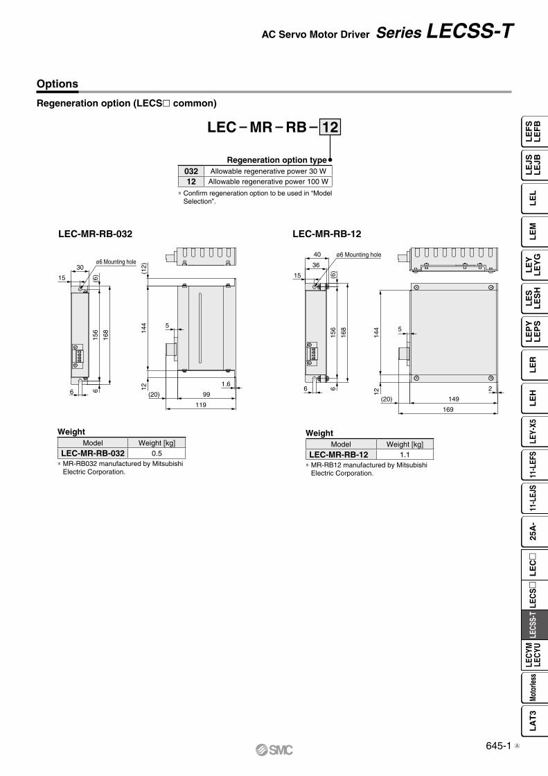
6
ø6 Mounting hole
(6)
156
168
6
30
15
1214
4(1
2)
5
1.6
(20)
119
99
(6)
ø6 Mounting hole40
36
15
168
156
66
149
5
144
12
(20)
169
2
12
Regeneration option type032 Allowable regenerative power 30 W
12 Allowable regenerative power 100 W
∗ Confirm regeneration option to be used in “Model Selection”.
LEC MR RB
WeightModel Weight [kg]
LEC-MR-RB-032 0.5∗ MR-RB032 manufactured by Mitsubishi
Electric Corporation.
WeightModel Weight [kg]
LEC-MR-RB-12 1.1∗ MR-RB12 manufactured by Mitsubishi
Electric Corporation.
Regeneration option (LECSl common)
LEC-MR-RB-032 LEC-MR-RB-12
Options
645-1
AC Servo Motor Driver Series LECSS-T
LE
FS
LE
FB
LE
LL
EJS
LE
JBL
EM
LE
YL
EY
GL
ES
LE
SH
LE
PY
LE
PS
LE
RL
EH
LEY-
X511
-LEF
S11
-LEJ
S25
A-
LEC
YMLE
CYU
LECS
S-T
LA
T3
Moto
rless
LEC
S
LE
C
A


Compatible PC
Hardware Requirements
Setup Software Compatible Driver
When using setup software (MR Configurator2™), use an IBM PC/AT compatible PC that meets the following operating conditions.
Setup software (MR Configurator2™) (LECSA, LECSB, LECSC, LECSS common)
LEC MRC2* SW1DNC-MRC2- manufactured by Mitsubishi Electric Corporation.
Refer to Mitsubishi Electric Corporation’s website for operating environment and version upgrade information.MR Configurator2™ is a registered trademark or trademark of Mitsubishi Electric Corporation.
USB cable
PC Setup software (MR Configurator2™)LECSS2-T
Display language
Adjustment, waveform display, diagnostics, parameter read/write, and test operation can be performed upon a PC.
EquipmentSetup software (MR Configurator2™)
LEC-MRC2
Note 1) 2) 3)
4) 5) 6) 7) 9)
PC
OS
Microsoft® Windows®8.1 Enterprise Operating SystemMicrosoft® Windows®8.1 Pro Operating SystemMicrosoft® Windows®8.1 Operating SystemMicrosoft® Windows®8 Enterprise Operating SystemMicrosoft® Windows®8 Pro Operating SystemMicrosoft® Windows®8 Operating SystemMicrosoft® Windows®7 Ultimate Operating SystemMicrosoft® Windows®7 Enterprise Operating SystemMicrosoft® Windows®7 Professional Operating SystemMicrosoft® Windows®7 Home Premium Operating SystemMicrosoft® Windows®7 Starter Operating SystemMicrosoft® Windows Vista® Ultimate Operating SystemMicrosoft® Windows Vista® Enterprise Operating SystemMicrosoft® Windows Vista® Business Operating SystemMicrosoft® Windows Vista® Home Premium Operating SystemMicrosoft® Windows Vista® Home Basic Operating SystemMicrosoft® Windows®XP Professional Operating System, Service Pack 2 or laterMicrosoft® Windows®XP Home Edition Operating System, Service Pack 2 or later
Available HD space
1 GB or more
Communication interface
Use USB port.
DisplayResolution 1024 x 768 or more
Must be capable of high color (16-bit) display.The connectable with the above PC
Keyboard The connectable with the above PC
Mouse The connectable with the above PC
Printer The connectable with the above PC
USB cable Note 8) LEC-MR-J3USB
Compatibledriver
Setup software
MR Configurator™ MR Configurator2™
LEC-MR-SETUP221 LEC-MRC2LECSA v v
LECSB v v
LECSC v v
LECSS-S v v
LECSS2-T — v
Nil Japanese version
E English version
C Chinese version
Options
Note 1) Before using a PC for setting LECSA point table method/program operation method, upgrade to version 1.18U (Japanese version)/version 1.19V (English version) or later. Refer to Mitsubishi Electric Corporation’s website for version upgrade information.
Note 2) Windows® and Windows Vista® are registered trademarks of Microsoft Corporation in the United States and other countries.
Note 3) On some PCs, setup software (MR Configurator2™) may not run properly.
Note 4) When Windows®XP or later is used, the following functions cannot be used.· Windows Program Compatibility mode· Fast User Switching· Remote Desktop· Large Fonts Mode (Display property)· DPI settings other than 96 DPI (Display property)· 64-bit OSs are not supported, except for
Microsoft® Windows®7 or later.Note 5) When Windows®7 is used, the following functions cannot be used.
· Windows XP Mode· Windows Touch
Note 6) When using this software with Windows Vista® or later, log in as a user having USER authority or higher.
Note 7) When Windows®8 is used, the following functions cannot be used.· Hyper-V· Modern UI style
Note 8) Order USB cable separately.· This cable is compatible with the setup software
(MR Configurator™: LEC-MR-SETUP221).Note 9) Using a PC for setting Windows®8.1, upgrade to
version 1.25B or later. Refer to Mitsubishi Electric Corporation’s website for version upgrade information.
646
AC Servo Motor Driver Series LECSS-T
LE
FS
LE
FB
LE
LL
EJS
LE
JBL
EM
LE
YL
EY
GL
ES
LE
SH
LE
PY
LE
PS
LE
RL
EH
LEY-
X511
-LEF
S11
-LEJ
S25
A-
LEC
YMLE
CYU
LECS
S-T
LA
T3
Moto
rless
LEC
S
LE
C
A
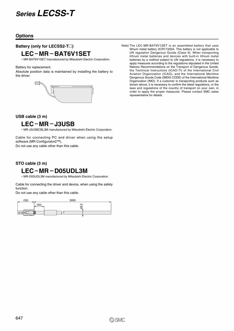
Options
Note) The LEC-MR-BAT6V1SET is an assembled battery that uses lithium metal battery 2CR17335A. This battery is not applicable to UN regulation Dangerous Goods (Class 9). When transporting lithium metal batteries and devices with built-in lithium metal batteries by a method subject to UN regulations, it is necessary to apply measures according to the regulations stipulated in the United Nations Recommendations on the Transport of Dangerous Goods, the Technical Instructions (ICAO-TI) of the International Civil Aviation Organization (ICAO), and the International Maritime Dangerous Goods Code (IMDG CODE) of the International Maritime Organization (IMO). If a customer is transporting products such as shown above, it is necessary to confirm the latest regulations, or the laws and regulations of the country of transport on your own, in order to apply the proper measures. Please contact SMC sales representative for details.
Battery (only for LECSS2-T)
LEC MR BAT6V1SET* MR-BAT6V1SET manufactured by Mitsubishi Electric Corporation.
Battery for replacement.Absolute position data is maintained by installing the battery to the driver.
USB cable (3 m)
LEC MR J3USB* MR-J3USBCBL3M manufactured by Mitsubishi Electric Corporation.
Cable for connecting PC and driver when using the setup software (MR Configurator2™).Do not use any cable other than this cable.
STO cable (3 m)
LEC MR D05UDL3M* MR-D05UDL3M manufactured by Mitsubishi Electric Corporation.
Cable for connecting the driver and device, when using the safety function.Do not use any cable other than this cable.
(33) 3000
(50)
ø6.
5
647
Series LECSS-T


![円弧型リニアサーボモータ Arc type Linear Servo Motor Compass Motor...5 Servo driver / Controller [ CⅡ series ] [ VCⅡseries ] Servo driver / Controller Line up VCⅡ-D](https://img.dokumen.tips/doc/110x75/60d73f7f99be0c5f5558ebe2/ffffoeff-arc-type-linear-servo-compass-motor-5-servo.jpg)