Embed Size (px)
Citation preview

Pinouts
AC Outlet On a polarized plug, the smaller of the two blades is the hot wire and the larger is the neutral.
NEMA 1-15 Non-Polarized plug
NEMA 5-15 – Standard ground plug and outlet
NEMA 5-20 – Standard ground outlet with 20 amp capability

Phono Connectors (RCA) Following is the common or standard wiring pinout for an RCA connector.
Tip (+)
Ground (-)
1/4" Mono Tip: hot (non-inverting) Sleeve: low (inverting) Sleeve: Shield (ground)
1/4" Phone - 2 Circuits/TS Following is the common or standard wiring pinout for two circuit 1/4" Phone connectors.
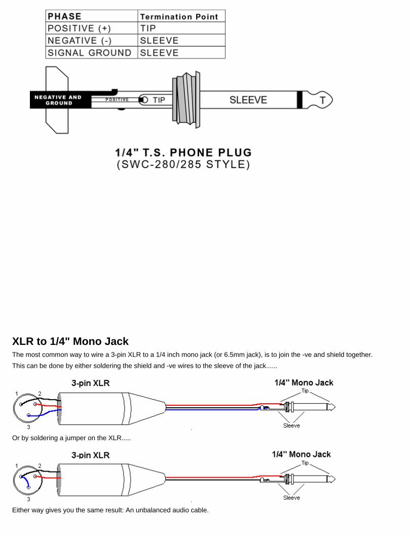
XLR to 1/4" Mono Jack The most common way to wire a 3-pin XLR to a 1/4 inch mono jack (or 6.5mm jack), is to join the -ve and shield together.
This can be done by either soldering the shield and -ve wires to the sleeve of the jack......
Or by soldering a jumper on the XLR.....
Either way gives you the same result: An unbalanced audio cable.

1/4" TRS Tip: hot (non-inverting) Ring: low (inverting) Sleeve: Shield (ground)
Balanced Line (Neutrik - NP3C Style) Following is the common or standard wiring pin out for 1/4" connectors.

XLR to 1/4" Stereo Jack (wired for balanced mono) The usual way to connect a 3-pin XLR to a 1/4" stereo jack is to use the following pin allocation:
XLR pin 1 to jack sleeve XLR pin 2 to jack tip XLR pin 3 to jack ring
This wiring configuration gives you a balanced mono audio cable.
Send and Return Circuits Unbalanced Following is the common or standard wiring pin out for 1/4" connectors.
Sleeve Common (ground)
Tip Send
Ring Return

1/4" Phone - 3 Circuits/TRS Following is the common or standard wiring pin out for 1/4" Phone connectors.
4 pin 3.5mm (2.5mm) plug connector
at the iPhone (2.5mm or 3.5mm, depends on model)
iPhone headphone (handsfree)
Pin Number
Pin Name
Description
1 Tip Left audio
2 Ring Right audio
3 Ring Common/Ground
4 Sleeve Microphone
Pressing the headset button shorts Microphone to Ground
Inserting a 3-pin plug into the iPhone's 4-pin receptacle would also short Mic to Common and the
L/R earphones will work correctly.
Speakon

Single Driver
Pin1 Positive (+)
Pin 1 Negative (-)
Pin 2 Positive - No Connection
Pin 2 Negative - No Connection
Dual Driver (two channels of the same signal)
Pin1 Positive driver 1 (+)
Pin 1 Negative driver 1 (-)
Pin 2 Positive driver 2 (+)
Pin 2 Negative driver 2 (-)
Speakon (continued)

Bi-amp or Stereo (two channels of differing signal)
Pin1 Positive low frequency or left (+)
Pin 1 Negative low frequency or left (-)
Pin 2 Positive high frequency or right (+)
Pin 2 negative high frequency or right (+)
Pin Name
Pin Number
Description
1+ Positive 1 This pin carries the signal from amp to the speaker
1- Negative
1 This pin carries the negative back to the amplifier (of channel one)
2+ Positive 2 Second positive from amp
2- Negative
2 Second negative back to amplifier from speaker (of channel 2)
The XLR connectors are used mostly in professional audio and video electronics cabling applications. Home audio and video electronics normally use RCA connectors. There is no common pinout - it depends on application.

3 pin XLR female connector
Balanced Audio (3 pole XLR):
Pin Signal Description
1 Ground / Screen
2 In phase / +ve / Hot
3 Out of phase / -ve / Cold
Unbalanced Audio (3 pole XLR):
Pin Signal Description
1 Ground / Screen
2 Signal
3 Ground / Screen (connect to pin 1)
Application Pin 1 Pin 2 Pin 3 Notes
D54 Screen No
connection
Signal (analogue multiplex)
Strand analog multiplex - 384 channelsSometimes uses an XLR4 connector for compatibility with AMX192
DMX512 (DMX)
Screen Data - Data +
Digital multiplex - 512 channelsStandard connector is the XLR5
TecPro Backbone
Earth/ Screen
Power +24VDC
Audio
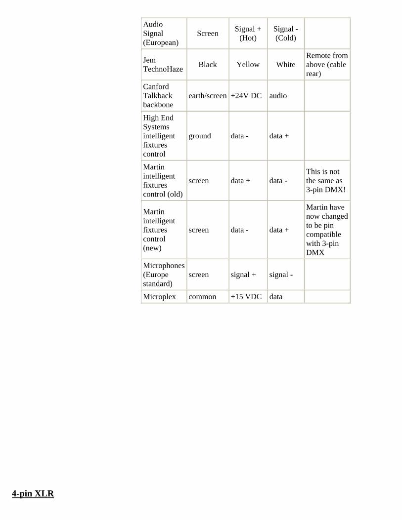
Audio Signal (European)
Screen Signal +
(Hot) Signal - (Cold)
Jem TechnoHaze
Black Yellow White Remote from above (cable rear)
Canford Talkback backbone
earth/screen +24V DC audio
High End Systems intelligent fixtures control
ground data - data +
Martin intelligent fixtures control (old)
screen data + data - This is not the same as 3-pin DMX!
Martin intelligent fixtures control (new)
screen data - data +
Martin have now changed to be pin compatible with 3-pin DMX
Microphones (Europe standard)
screen signal + signal -
Microplex common +15 VDC data
4-pin XLR

4 pin XLR
female connector
Application Pin 1 Pin 2 Pin 3 Pin 4 Notes
AMX 192 screen (analogue 0V)
clock + analogue multiplex
clock -
Canford Talkback 1cct headset
Mic earth/scr
Mic signal
Earphones earth/scr
Earphones signal
Clearcom talkback headset
Mic earth/scr
Mic signal
Earphones earth/scr
Earphones signal
Diversitronics (analogue) superstrobes
signal ground supply (+ve)
not used
Pyro Pack Control
channel 1channel 2
channel 3 common
Rosco gobo rotator
Forward A
Reverse A
Forward B
Reverse B
Scroller (generic)
ground -ve data +ve data
+24VDC or +48VDC power
NOT Wybron!
Wybron Scroller
+24v DC -ve data +ve data ground Non-standard!
4 pin XLR
male connector
5-pin XLR
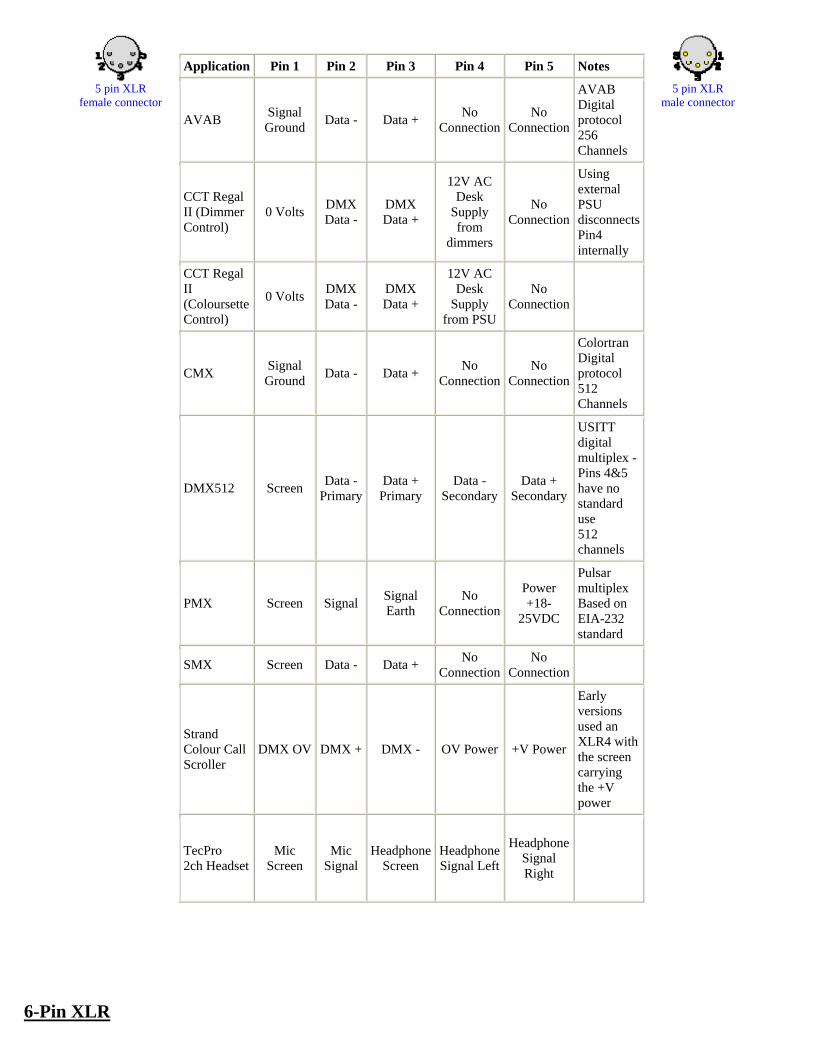
5 pin XLR
female connector
Application Pin 1 Pin 2 Pin 3 Pin 4 Pin 5 Notes
AVAB Signal Ground
Data - Data + No
Connection No
Connection
AVAB Digital protocol 256 Channels
CCT Regal II (Dimmer Control)
0 Volts DMXData -
DMX Data +
12V AC Desk
Supply from
dimmers
No Connection
Using external PSU disconnects Pin4 internally
CCT Regal II (Coloursette Control)
0 Volts DMXData -
DMX Data +
12V AC Desk
Supply from PSU
No Connection
CMX Signal Ground
Data - Data + No
Connection No
Connection
Colortran Digital protocol 512 Channels
DMX512 Screen Data -
Primary Data +
Primary Data -
Secondary Data +
Secondary
USITT digital multiplex - Pins 4&5 have no standard use 512 channels
PMX Screen Signal Signal Earth
No Connection
Power +18-
25VDC
Pulsar multiplex Based on EIA-232 standard
SMX Screen Data - Data + No
Connection No
Connection
Strand Colour Call Scroller
DMX OV DMX + DMX - OV Power +V Power
Early versions used an XLR4 with the screen carrying the +V power
TecPro 2ch Headset
Mic Screen
Mic Signal
HeadphoneScreen
HeadphoneSignal Left
HeadphoneSignal Right
5 pin XLR
male connector
6-Pin XLR

6 pin XLR
female connector
Application Pin 1 Pin 2 Pin 3 Pin 4 Pin 5 Pin 6 Notes
Canford Talkback multicircuit backbone
earth/scr+24V DC
audio 1
audio 2
audio 3
audio 4
Compulite Riggers Remote
ground data from remote
data to remote
+12V -12Vnot used
Strand GSX / LBX rigger's remote
earth/scr +10V data +485
data -485
232 Rx
232 Tx
6 pin XLR
male connector
5-pin DIN Audio

5 pin DIN
female connector at the peripheral
Peripheral Connected In L
In R
Out L
Out R
Ground
Amplifier Pickup, tuner
3 5 2
Amplifier Taperecorder 3 5 1 4 2
Tuner Amplifier 3 5 2
Tuner Taperecorder 1 4 2
Recordplayer Amplifier 3 5 2
Taperecorder Amplifier 1 4 3 5 2
Taperecorder Receiver 1 4 3 5 2
Taperecorder Microphone 1 4 2
5 pin DIN
male connector
6-pin DIN Audio
6 pin DIN
male connector
Application Pin 1 Pin 2 Pin 3 Pin 4 Pin 5 Pin 6 Notes
Compulite Riggers Remote
ground data from remote
not used data to remote
+12V -12V
CCT Regal II Desk PSU
0V not used
not used DMX + 24V AC DMX -
Green Ginger DMX
ground DMX 1 true
DMX 1 complement
DMX 2 true (not used)
DMX 2 complement (not used)
supply +ve
Green Ginger/ Lightprocessor analogue control
channel 1
channel 2
channel 3 channel 4
+ve supply ground
6 pin DIN
female connector
MIDI

MIDI=Musical Instrument Digital Interface.
5 pin DIN
female connector at the peripheral
MIDI is a digital communications protocol, introduced in 1983 by a group of musical instrument manufacturers.
Pin Name Description
1 n/c Not connected
2 n/c Not connected
3 n/c Not connected
4 CSRC Current Source
5 CSINK Current Sink
5 pin DIN male connector
MIDI Cable Schematic
5 pin DIN male connector
at the 1st peripheral
1st 2nd
Shield 2 2
Current Source 4 4
Current Sink 5 5
Note: Although pin 2 only is connected at MIDI Out, it´s simpler to connect it to both ends.
5 pin DIN male connector
at the 1st peripheral
PC to MIDI Cable

´AMK-03´ cable
15 pin D-SUB male connector 5 pin DIN male connector at the computer at the MIDI device

The game port is the traditional connection for video game input devices on an x86-based PCs. The game port is an on-board feature of many motherboards but may be integrated with a PC I/O or sound card.
15 pin D-SUB
female connector at the computer
15 pin D-SUB male connector
at the joystick cable
Game ports use DB-15 connectors, and usually double as connectors for MIDI instruments. To use a game port with MIDI instruments, one must obtain a cable with both DB-15 and 5-pin DIN connectors (similar to old-style pre-PS/2 keyboard connectors known as Baby AT or AT5 connectors).
Pin Name Dir Description
1 +5V +5 VDC
2 /B1 Button 1
3 X1 Joystick 1 - X
4 GND Ground
5 GND Ground
6 Y1 Joystick 1 - Y
7 /B2 Button 2
8 +5V +5 VDC
9 +5V +5 VDC
10 /B4 Button 4
11 X2 Joystick 2 - X
12 MIDITXD MIDI Transmit
13 Y2 Joystick 2 - Y
14 /B3 Button 3
15 MIDIRXD MIDI Receive

miniDIN to DIN adapter for Creative LivedriveII MIDI IN and MIDI OUT pinout With this adapter, you can connect a MIDI instrument with standard cables to the Creative LivedriveII
5 pin mini-din connector at the LivedriveII female
miniDIN
LivedriveII female
miniDIN Pin
Name
LivedriveII female
miniDIN Pin
Number
Direction
Male 5 pin DIN of MIDI
cable Pin
Number
Male 5 pin DIN of MIDI
cable Pin
Name
Description
NC 4 --- 2 Shield
Current source
5 --- 4 Current Source
Current Sink
6 --- 5 Current
Sink
NC 1 --- 1 NC
NC 3 --- 3 NC
5 pin mini-DIN male is equal to 6 pin mini-DIN male PS/2 without pin 2. Tested with CASIO Keyboard.
5 pin DIN female connector
at the Male 5 pin DIN of MIDI cable

DMX (Digital MultipleX) is a communications protocol used mainly to control stage lighting. It is a form of the RS-485 architecture.
5 pin XLR male connector
Latest ESTA standard (approved by ANSI) known as "Entertainment Technology — USITT DMX512–A — Asynchronous Serial Digital Data Transmission Standard for Controlling Lighting Equipment and Accessories", also known as "E1.11, USITT DMX512–A", or just "DMX512-A".
DMX is the primary method for linking controllers, dimmers, advanced fixtures and special effects devices such as foggers and moving lights. A DMX512 controller is connected to fixtures or devices in a daisy-chain link. Each device has a DMX in and generally a DMX out XLR 5 pin connector - sometimes marked as DMX thru. The DMX out on the controller is linked via a DMX512 cable to the DMX in on the first fixture. A second cable then links the DMX out on the first fixture to the next device, and so on - up to 512 devices. In general, the final, empty, DMX out connector should have a DMX512 terminating plug attached into it, which is simply a 120ohm resistor joining pins 2 and 3 of the connector. Many modern devices negate this requirement, as they are capable of auto-terminating the link.
Pin Signal Description
1 Signal Common
2 Data Minus
3 Data Plus
4 Not used
5 Not used
Originally intended for feeding diagnostic data back to the DMX512 controller, but never been implemented. Sometimes used to carry other data or power
DMX512 Data are sent using RS-485 voltage levels and cabling practices. Data are transmitted serially at 250 kbit/s and is grouped into packets of up to 513 bytes. Data are sent with 1 start bit and 2 stop bits, LSB first.

The start of a packet is signified by a break of at least 88 uS. Receivers detect the break and reset their Receiving code. Then up to 513 bytes are sent. The first byte is always the "Start code" byte. This tells receivers which kinds of data are being sent. For normal dimmer/level data, a start code of 0x00 is used. Other start codes are used for proprietary systems or for the RDM extension to DMX.
The remaining bytes make up the actual level data. Up to 512 bytes can be sent, and it is the job of the receiver to count the bytes to keep track of the channels. As there is no error detection or correction in DMX, it is vitally important for receivers not to miss bytes, and to discard packets if framing or buffer overflow errors are detected. A full packet takes approx. 23 mS to send (44 Hz refresh rate) - for higher refresh rates fewer channels can be sent.
Moving lights use adjacent DMX512 channels to control different aspects of their behavior. Modern DMX512 controllers have libraries of data about fixtures telling them how to map attributes to DMX512 channels. The controller could then have separate ways of selecting gobos and gobo rotation, even though on a particular fixture they are controlled by a single DMX512 channel.
The DMX512 output is designed to feed 32 'units' of load. A single fixture may represent a fraction of a unit of load; however the cabling in between the fixtures can degrade the signal significantly. To deal with this, and cable management issues, DMX512 buffers are often used. These have one DMX512 in but many DMX512 outs, all feeding identical data. Each output from the DMX512 buffer can feed 32 units, so by using DMX512 buffers it is possible to split the signal from a controller to hundreds of fixtures.
PC DMX pinout for Martin Lightjockey interface card - common for professional lighting use the Martin professional Lightjockey software with DMX interface, this are the pinout for the one (512ch) or four (2048ch) universes corresponding to the version dj or club.
9 pin D-SUB male connector
at the XLR Terminal
d-sub 9
Pin Name Description
1 - XLR Male Pin 1 (Negative) [universe 2+4]
2 + XLR Female Pin 3 (Positive) [universe 1+3]
3 earth XLR Female Pin 2 (Positive) [universe 1+3]
5 - XLR Feale Pin 1 (Negative) [universe 1+3]
6 earth XLR Male Pin 2 (ground) [universe 2+4]
9 + XLR Male Pin 3 (Positive) [universe 2+4]

VHS Video Camera Out
10 pin DIN female connector
at the video camera (facing you)
There seems to be no clear standard for VHS Video Cameras. Column "Name" is the most common function. Three alternative functions that could apply for some cameras are presented in columns named "Alt Name X".
Pin Name Alt Name 1 Alt Name 2 Alt Name 3
1 video out video in/out
2 video gnd
3 serial data
4 tally and clock reset in
5 audio out right standby out audio in
6 pause
7 audio out audio out left
8 audio gnd
9 power gnd
10 +12V power

Trailer Wiring Diagrams
4 Way Systems Flat molded connectors allow basic hookup for three lighting functions; right turn signal / stop light (green), left turn
signal / stop light (yellow), taillight / license / side marker (brown) and a ground (white).
4 way tow vehicle side.
4 way trailer side.
5 Way Systems Same as 4 way system listed above but adds a extra red or black auxiliary power wire.
5 way tow vehicle side.
5 way trailer side.

6 Way Systems Round 1 1/4" diameter metal connector allows 1 or 2 additional wiring and lighting functions such as back up lights, auxiliary 12v power or electric brakes. Note: The black (12v) and blue (electric brakes) may need to be reversed to
suit the trailer. Check with a test light or VOM.
6 way tow vehicle side.
6 way trailer side.
7 Way Systems Round 2" diameter connector allows additional pin for auxiliary 12v power or backup lights.
7 way RV flat blade tow vehicle side.
7 way RV flat blade trailer side.

Common Computer Connectors (images are not to scale)

Common Computer Connectors (images are not to scale)
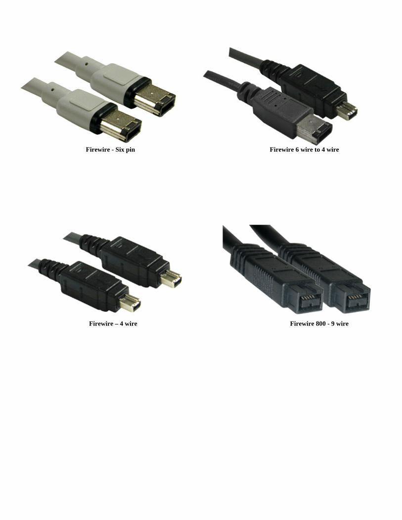
Firewire - Six pin Firewire 6 wire to 4 wire
Firewire – 4 wire Firewire 800 - 9 wire
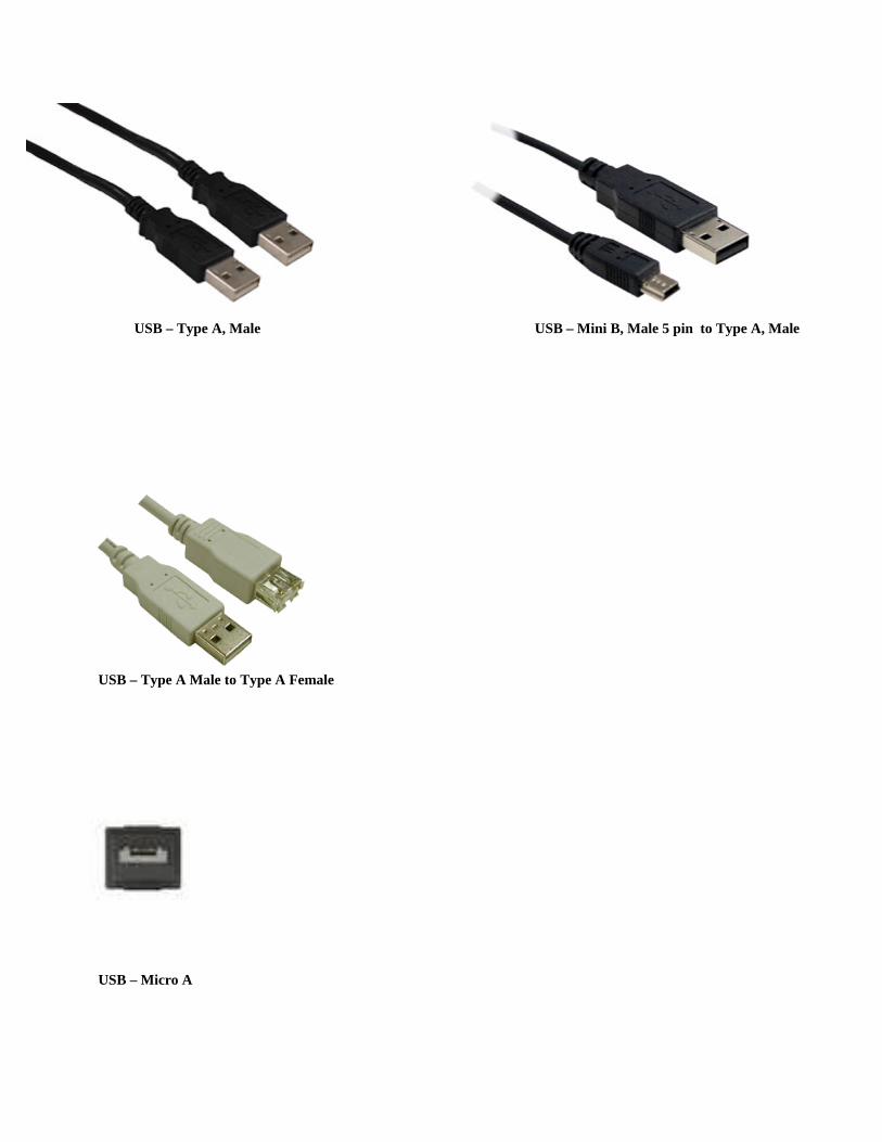
USB – Type A, Male USB – Mini B, Male 5 pin to Type A, Male
USB – Type A Male to Type A Female
USB – Micro A

USB – Micro B
USB – Micro A
USB – Micro 3 b
USB – Micro A

USB – Mini B
USB – Mini B 4 pin
SC Fiber (Duplex) ST Fiber
LC Fiber (Duplex) FC Fiber

MTRJ to SC MTRJ to ST Additional References Dash http://www.dashdist.com Dalco http://www.dalco.com Media College http://www.mediacollege.com/ Crown Audio http://www.crownaudio.com/ Automotive Accessories Connection: http://www.accessconnect.com