Embed Size (px)
Citation preview

AC Motor Systems
BHF Series ································································B-70ES01/ES02 ······························································B-86US Series ································································B-116
Technical Reference················································F-1General Information················································G-1
Additional Information
B-69
Sp
eedC
on
trolS
ystems
Bru
shless D
C M
oto
r System
sDC
Inp
ut
AC
Inp
ut
AC
Mo
tor S
ystems
BX
FBL2
AX
UA
XH
BH
FES
US
Introduction
Before Using aSpeed Control
System

B-70
Sp
eedC
on
trolS
ystems
Specifications B-72 Characteristics B-75System Configuration B-71Features B-70 Specifications B-72 Characteristics B-75System Configuration B-71Features B-70
AC Motor Systems
BHF Series200 W (1/4 HP) Frame Size: 4.09 in. sq. (104 mm sq.)
The BHF Series consists of a high-power 200 W (1/4 HP) ACspeed-control motor combined with a dedicated inverter.Each motor comes pre-assembled with a gearhead.
Combination Type (Pre-assembled Gearmotors)The combination type (Pre-assembled Gearmotors) comes with themotor and its dedicated gearhead already assembled. This simplifiesinstallation in equipment. Motors and gearheads are also availableseparately so they can be on hand to make changes or repairs.
Features Excellent speed stabilityThe combination of a dedicated inverter with a motorachieves excellent speed stability with a fluctuation of only3%. The inverter is already optimized for use with thegearmotor, so detail adjustments are not required to achieveaccurate speed control.
Automatic control of an electromagnetic brakeThe AC speed-control system with an electromagnetic brakeallows automatic on/off control of the electromagnetic brake(power off activated type) on the inverter side. No longer willit be necessary to prepare a separate power supply orprogram a control sequence.
Smallest frame size among 200 W (1/4 HP) motorsThe BHF Series achieves an output of 200 W (1/4 HP), thehighest among Oriental Motor’s standard AC motors, with thesmallest frame size [4.09 inch (104 mm) square] in thatclass. This allows for a reduction in the size of yourequipment.
Safety Standards and CE Marking
When the system is approved under various safety standards, the model nameson the motor and inverter nameplates are the approved model names.List of Motor CombinationsPage B-85
Details of Safety StandardsPage G-2 The EMC value changes according to the wiring and layout. Therefore, the final
EMC level must be checked with the motor/inverter incorporated in the user’sequipment.
Wiring length of up to 164 feet (50 m)The wiring distance between the motor and inverter can beextended to a maximum of 164 feet (50 m).
Full-range functionalityThe BHF Series offers a variety of functions such as alarmoutput, speed monitor output and individualacceleration/deceleration setting. The driver also has a built-in I/O power supply.
Wide product variationsPre-assembled gearmotors are available in a right-angleshaft type equipped with a hypoid gear (hollow shaft, solidshaft) and a parallel shaft type. A wide range of gear ratiosare available. An electromagnetic brake type is alsoavailable.
Global specificationsThe BHF Series conforms to international power-supplyvoltage specifications, including single-phase 100-115 VAC,single-phase 200-230 VAC and three-phase 200-230 VAC.All units comply with the UL/CSA standards and bear the CEmark as proof of compliance with the Low Voltage Directiveand EMC Directive.
Standards Certification Body Standards File No. CE Marking
Motor
Inverter
UL1004UL2111CSA C22.2 No.100CSA C22.2 No.77EN60950EN60034-1EN60034-5IEC60034-11IEC60664-1UL508CCSA C22.2 No.14EN50178EN60950
UL
Conforms to EN/IEC Standards
Conforms to EN/IEC Standards
UL
E64197
E171462
Low VoltageDirectives /
EMC Directives
BHF Series
B-71Dimensions B-76 Connection and Operation B-81 Motor and Inverter Combinations B-85Dimensions B-76 Connection and Operation B-81 Motor and Inverter Combinations B-85
Sp
eedC
on
trolS
ystems
Bru
shless D
C M
oto
r System
sDC
Inp
ut
AC
Inp
ut
AC
Mo
tor S
ystems
BX
FBL2
AX
UA
XH
BH
FES
US
Introduction
Before Using aSpeed Control
System System Configuration
Product Number Code
The system configuration shown is an example. Other configurations are available.
Mounting Bracket(Accessories)( Page A-204)
Combination Type( Pre-assembled Gearmotor )
BHF Series
Inverter
Programmable Controller
AC Power Supply
DIN Rail Mounting Plate (Accessories)( Page A-217)
(Not Supplied)
(Not Supplied)
Flexible Coupling(Accessories)( Page A-208)
BHF 6 2 A M T- 100 RH
Output Power2: 200W
VoltageA: Single-Phase
100-115 VACC: Single-Phase
200-230 VACS: Three-Phase
200-230 VAC
SeriesBHF Series
Motor Frame Size6: 4.09 in. sq.
(104 mm sq.)
None: without Electro-magnetic Brake
M: with Electromagnetic Brake
T: Terminal Box Type
Gear Ratio or Shaft TypeNumber:
Gear RatioA: Round Shaft
Type
Gearhead Type(Combination type only)None: Parallel ShaftRH: Right-Angle Hollow
Shaft TypeRA: Right-Angle Solid
Shaft Type
External SpeedPotentiometer (Accessories)( Page A-216)
Regeneration Unit(Accessories)( Page A-218)

B-72
Sp
eedC
on
trolS
ystems
Specifications B-72 Characteristics B-75System Configuration B-71Features B-70 Specifications B-72 Characteristics B-75System Configuration B-71Features B-70
Product Line Speed Control SystemCombination Type
Round Shaft Type Round Shaft Type
Type
Combination Typewith Right-Angle
Hollow Shaft
Combination Type with Right-Angle
Solid Shaft
Combination Type with Parallel Shaft
Power Supply VoltageSingle-Phase100-115 VACSingle-Phase200-230 VACThree-Phase200-230 VACSingle-Phase100-115 VACSingle-Phase200-230 VACThree-Phase200-230 VACSingle-Phase100-115 VACSingle-Phase200-230 VACThree-Phase200-230 VAC
Model
BHF62AT-RH
BHF62CT-RH
BHF62ST-RH
BHF62AT-RA
BHF62CT-RA
BHF62ST-RA
BHF62AT-
BHF62CT-
BHF62ST-
Gear Ratio
5180
5180
5180
5180
5180
5180
3180
3180
3180
Enter the gear ratio in the box () within the model name.
Type
Round Shaft Type
Power SupplySingle-Phase 100-115 VACSingle-Phase 200-230 VACThree-Phase 200-230 VAC
ModelBHF62AT-ABHF62CT-ABHF62ST-A
ModelCombination Type
Round Shaft TypeOutput PowerRated SpeedRated TorqueStarting Torque
Permissible Torque
Permissible Load Inertia J
Speed Control Range
Power Source
Speed Regulation
HP (W)r/min
oz-in (N·m)oz-in (N·m)
oz-in (N·m)
oz-in2 (104 kg·m2)
r/minVoltageFrequencyRated Input CurrentMax. Input CurrentLoadVoltageTemperature
BHF62AT-RHBHF62AT-RA
BHF62AT-BHF62AT-A
1/4 (200)1500
180 (1.27)180 (1.27)
1001500 r/min: 180 (1.27)1800 r/min: 151 (1.07), 2400 r/min: 85 (0.6)
44 (8)
1002400
50 Hz/60 Hz
3% Max. (0Rated Torque, at 1500 r/min)3% Max. (Power supply voltage 10% at 1500 r/min with no load)3% Max. [32°F122°F (0°C50°C) at 1500 r/min with no load]
BHF62CT-RHBHF62CT-RA
BHF62CT-BHF62CT-A
BHF62ST-RHBHF62ST-RA
BHF62ST-BHF62ST-A
The permissible load inertia specified above is only applicable for the round shaft types. Permissible Load Inertia for the Combination Types Page B-75 The values for each specification applies to the motor only. Enter the gear ratio in the box () within the model name.
Specifications Speed Control System
Speed Control System with Electromagnetic BrakeCombination Type
Type
Combination Typewith Right-Angle
Hollow Shaft
Combination Typewith Right-Angle
Solid Shaft
Combination Typewith Parallel Shaft
Power Supply VoltageSingle-Phase100-115 VACSingle-Phase200-230 VACThree-Phase200-230 VACSingle-Phase100-115 VACSingle-Phase200-230 VACThree-Phase200-230 VACSingle-Phase100-115 VACSingle-Phase200-230 VACThree-Phase200-230 VAC
Model
BHF62AMT-RH
BHF62CMT-RH
BHF62SMT-RH
BHF62AMT-RA
BHF62CMT-RA
BHF62SMT-RA
BHF62AMT-
BHF62CMT-
BHF62SMT-
Gear Ratio
5180
5180
5180
5180
5180
5180
3180
3180
3180
Enter the gear ratio in the box () within the model name.
Type
Round Shaft Type
Power SupplySingle-Phase 100-115 VACSingle-Phase 200-230 VACThree-Phase 200-230 VAC
ModelBHF62AMT-ABHF62CMT-ABHF62SMT-A
Single-Phase 100-115 VAC10%
5.4 A8.3 A
Single-Phase 200-230 VAC10%
3.1 A4.9 A
Three-Phase 200-230 VAC10%
1.75 A2.7 A
RrC

B-73Dimensions B-76 Connection and Operation B-81 Motor and Inverter Combinations B-85Dimensions B-76 Connection and Operation B-81 Motor and Inverter Combinations B-85
Sp
eedC
on
trolS
ystems
Bru
shless D
C M
oto
r System
sDC
Inp
ut
AC
Inp
ut
AC
Mo
tor S
ystems
BX
FBL2
AX
UA
XH
BH
FES
US
Introduction
Before Using aSpeed Control
System
ModelCombination Type
Round Shaft TypeOutput PowerRated SpeedRated TorqueStarting Torque
Permissible Torque
Permissible Load Inertia J
Speed Control Range
Power Source
Speed Regulation
Electromagnetic Brake Holding Brake TorqueLowering Operation
HP (W)r/min
oz-in (N·m)oz-in (N·m)
oz-in (N·m)
oz-in2 (104 kg·m2)
r/minVoltageFrequencyRated Input CurrentMax. Input CurrentLoadVoltageTemperature
oz-in (N·m)
BHF62AMT-RHBHF62AMT-RA
BHF62AMT-BHF62AMT-A
1/4 (200)1500
180 (1.27)180 (1.27)
1001500 r/min: 180 (1.27)1800 r/min: 151 (1.07), 2400 r/min: 85 (0.6)
44 (8)
1002400
50 Hz/60 Hz
3% Max. (0Rated Torque, at 1500 r/min)3% Max. (Power supply voltage 10% at 1500 r/min with no load)3% Max. [32°F122°F (0°C50°C) at 1500 r/min with no load]
210 (1.5)
Connecting the regeneration unit [Accessories (Sold Separately)], Max. output 100 W (5 minutes rating)
BHF62CMT-RHBHF62CMT-RA
BHF62CMT-BHF62CMT-A
BHF62SMT-RHBHF62SMT-RA
BHF62SMT-BHF62SMT-A
The permissible load inertia specified above is only applicable for the round shaft types. Permissible Load Inertia for the Combination Types Page B-75 The values for each specification applies to the motor only. Enter the gear ratio in the box () within the model name.
Speed Control System with Electromagnetic Brake
Single-Phase 100-115 VAC10%
5.4 A8.3 A
Single-Phase 200-230 VAC10%
3.1 A4.9 A
Three-Phase 200-230 VAC10%
1.75 A2.7 A
Common Specifications Speed Control System / Speed Control System with Electromagnetic Brake
Acceleration/Deceleration Time
Speed Control Method
Input Signal
Output Signal
Protection Functions
RatingMotor Insulation Class
0.125 seconds (at 1000 r/min)Any one of the following methods:1. By built-in potentiometer (1 piece) 2. By external potentiometer (20 kΩ 1/4 W) 3. By DC voltage control (05 VDC) Photocoupler input Input impedance 2.4 k ΩOperates at 12 VDCCommon to CW/CCW, Speed setting mode selection, Slow down, Alarm resetOpen collector output External use conditions 26.4 VDC, 10 mA max.Common to SPEED OUT (12P/R), ALARM OUT If any of the protective functions of the inverter are triggered, the ALM output will be turned off and the ALM LED on the front panel of theinverter will blink or turn on while the motor current is interrupted to stop the motor.• Overload protection: A load exceeding the rated torque has been applied to the motor for 5 seconds or more.• Overvoltage protection: The voltage applied to the inverter has exceeded the rated voltage by approximately 30% or more.
The motor is being operated beyond the lowering operation's ability.• Overcurrent protection: An excessive current is flowing within the inverter.• Undervoltage protection: The power-supply voltage has dropped below the rated voltage by approximately 15% or more.• Circuit overheat protection: The ambient operating temperature for the inverter has exceeded its upper limit.• Motor open circuit protection: The motor cable has an open circuit or improper connection.• EEPROM Error: An error was detected in the EEPROM.
ContinuousClass B (266°F [130°C])
RrC
Item Specifications

B-74
Sp
eedC
on
trolS
ystems
Specifications B-72 Characteristics B-75System Configuration B-71Features B-70 Specifications B-72 Characteristics B-75System Configuration B-71Features B-70
General Specifications
Size of heat radiation plate: 9.06 inch 9.06 inch (230 mm 230 mm), 0.20 inch (5 mm) in thickness (material: aluminum)
Item
Insulation Resistance
Dielectric Strength
Temperature Rise
Ambient Temperature
Ambient Humidity Degree of Protection
Motor
100 MΩ or more when measured by a 500 VDC megger between thewindings and the frame after rated motor operation under normalambient temperature and humidity.
Sufficient to withstand 1.5 kV at 50 Hz and 60 Hz applied between thewindings and the frame for 1minute after rated motor operation undernormal ambient temperature and humidity.
126°F (70°C) or less in the coil, as measured by the resistance changemethod after rated operation with gearhead or similar heat radiationplate installed.14°F104°F (10°C to 40°C)14°F122°F (10°C to 50°C) for 100/200 VAC(nonfreezing)
85% maximum (noncondensing) IP54 (excluding the motor-installation surface of the round shaft type)
Inverter100 MΩ or more when measured by a 500 VDC megger between thepower supply input terminal and the Protective Earth terminal andbetween the power supply input terminal and the I/O terminal aftercontinuous operation under normal ambient temperature andhumidity. Sufficient to withstand 1.5 kV (3 kV) at 50 Hz and 60 Hz appliedbetween the power supply input terminal and the Protective Earthterminal (between the power supply input terminal and the I/Oterminal) for 1 minute after continuous operation under normalambient temperature and humidity.
––––––––––––––
32°F122°F (0°C50°C) (nonfreezing)
85% maximum (noncondensing) IP10
Permissible Torque for Combination Type Right-Angle Shaft
Permissible Overhung Load and Permissible Thrust LoadThe overhung load and thrust load of the gearhead's output shaft affect the bearing life. Make sure the overhung load and thrustload do not exceed the values shown in the table below.
Enter the gear ratio in the box () within the model name. Direction of rotation of the motor and that of the gear output shaft are the opposite.
Model
BHF62AT-RH/RA, BHF62AMT-RH/RABHF62CT-RH/RA, BHF62CMT-RH/RABHF62ST-RH/RA, BHF62SMT-RH/RA
Gear RatioMotor Output Speed
1001500 r/min
1800 r/min
2400 r/min
5
404.6343.919.42.2
9
738.3617343.9
15
12313.910311.7586.6
30
24027.820023.411513.1
50
350403203719321.9
100
48054.548054.538043
180
530605306053060
Unit = Upper values: lb-in/Lower values: N·m
Parallel Shaft
Enter the gear ratio in the box () within the model name. A colored background indicates gear shaft rotation in the same direction as the motor shaft; a white background indicates rotation in the opposite direction.
Model
BHF62AT-, BHF62AMT-BHF62CT-, BHF62CMT-BHF62ST-, BHF62SMT-
Gear RatioMotor Output Speed
1001500 r/min
1800 r/min
2400 r/min
3
303.4252.914.11.6
5
505.7424.8232.7
9
9110.3768.7434.9
15
14516.412213.8687.7
30
29032.824027.613715.5
50
350403504021024.3
100
350403504035040
180
350403504035040
Unit = Upper values: lb-in/Lower values: N·m
With the hollow shaft type, the permissible overhung load is measured from the flange-mounting surface. Enter the voltage (A, C, S) in the box ( ). Enter the gear ratio in the box () within the model name. Permissible Overhung Load and Thrust Load for Round Shaft Type Page A-11
Model
BHF62 T-RHBHF62 MT-RHBHF62 T-RABHF62 MT-RABHF62 T-BHF62 MT-
Gear Ratio
53050180530
50180330
50180
from the tip of the shaft0.39 inch (10 mm)
Permissible Overhung Load [lb. (N)]
270 (1200)490 (2200)200 (900)380 (1700)123 (550)146 (650)
from the tip of the shaft0.79 inch (20 mm)
240 (1100)450 (2000)220 (1000)410 (1850)180 (800)220 (1000)
Permissible Thrust Load lb. (N)
67 (300)
67 (300)
45 (200)

B-75Dimensions B-76 Connection and Operation B-81 Motor and Inverter Combinations B-85Dimensions B-76 Connection and Operation B-81 Motor and Inverter Combinations B-85
Sp
eedC
on
trolS
ystems
Bru
shless D
C M
oto
r System
sDC
Inp
ut
AC
Inp
ut
AC
Mo
tor S
ystems
BX
FBL2
AX
UA
XH
BH
FES
US
Introduction
Before Using aSpeed Control
System
Speed — Torque CharacteristicsThe characteristics shown below are only applicable for the motors only.Continuous Duty Region: Continuous operation is possible in this region.Common to BHF Series
Enter the voltage (A, C, S) in the box ( ). Enter the gear ratio in the box () within the model name.
ModelBHF62 T-RH, BHF62 T-RABHF62 MT-RH, BHF62 MT-RABHF62 T-BHF62 MT-
3
9818
5
27050
9
880162
15
2400450
30
98001800
50
270005000
100
270005000
180
270005000
Unit = Upper values: oz-in2/Lower values: 104 kg·m2 Permissible Load Inertia J for the Combination Type
01500500 2000
Speed [r/min]
Torq
ue [o
z-in
]
Torq
ue [N
•m]
0
0.5
1.0
1.5
Continuous Duty Region
1000
2400 r/min
1/4 HP (200 W)180 oz-in(1.27 N•m)
85 oz-in(0.6 N•m)
1800 r/min
151 oz-in(1.07 N•m)
2500
50
100
150
200
Vertical Drive (Gravitational Operation)The BHF Series achieves stable speed control duringgravitational operation.
During vertical movement (gravitational operation), such asthe application illustrated below, normally an external forcecauses the motor to rotate and function as a powergenerator. If this energy is applied to the inverter, an errorwill occur. A regeneration unit (sold separately ) can convertregenerative energy into thermal energy for dissipation. Usethe optional regeneration unit EPRC-400P when using themotor for vertical drive applications or when braking a largeinertial load quickly.
Regenerative power: 100 W (5-minute rating)Instantaneous regenerative power: 300 W
Regenerative powerThe regenerative power may be calculated roughly using theequation shown below for reference.
Regenerative power (W) = 0.1047 TL [N·m] N [r/min]TL: Load torque N: Speed
Use the electromagnetic-brake type for gravitational operation.
WorkW
Gravitational operation ability
Use the time shown below as a guideline when performing continuous gravitational operation:
: Operating range in which regenerative power is 100 W or lessAllowable time for continuous gravitational operation: 1 minute, 30% ED
: Operating range in which regenerative power exceeds 100 W Allowable time for continuous gravitational operation: 1 minute, 20% ED
Example: 1 minute, 30%Under gravitational operation: 60 seconds
Non-gravitational operation: 140 seconds
60 seconds (1 minute) is the maximum continuous gravitational operation time allowed.
0
-0.4
-0.8
-1.2
-1.6
00 1000 2000
1800 2400500 1500 2500
Speed [r/min]
Torq
ue [N
•m]
Torq
ue [o
z-in
]
151 oz-in(1.07 N•m)
85 oz-in(0.6 N•m)
180 oz-in(1.27 N•m)
-50
-100
-150
-200
Gear Ratio/

B-76
Sp
eedC
on
trolS
ystems
Specifications B-72 Characteristics B-75System Configuration B-71Features B-70 Specifications B-72 Characteristics B-75System Configuration B-71Features B-70
Dimensions Scale 1/4, Unit = inch (mm)
Mounting screws are included with the combination type parallel shaft. Page B-133
Enter the gear ratio in the box () within the model name.
Motor/Gearhead (Combination Type with Right-Angle Hollow Shaft)BHF62AT-RH, BHF62CT-RH, BHF62ST-RHMotor Model: BHM62T-G2Gearhead Model: BH6G2-RHWeight: 22 lb. (10.0 kg)d A301
6.06 (154)6.30 (160)
4.
06 (
103)
1.10 Max.(28 Max.)
2.95 (75) 0.35 (9)
4.09
(10
4)
1.69
(43)
2.44 (62)
A'
A
1.57 (40)
4.02 (102)0( 580.046)
02.28350.0018
0.00130.9843 0 0.
16
(4)
0.63
(16)
3.90
(99)
4.65
(118
)
0.033( 25 0 )
(1200.5)4.720.02
1.11
(2
8.3)
0.04(8 0 )0.0016
0.31 0
0.335 (8.5)4 Holes
2.60 (66)
0.19 (4.8)
0.59(15)
1.18 (30)
4.30 (109.3)
1.18 (30)
0.59(15)
FlangeMounting Surface
Section AA'(Detail drawing of output shaft)
0.06 (1.5) 0.06 (1.5)
Groove for Retaining Ring0.21( 26.2 0 )0
+0.0081.03
0 0(8
0.03
6)
(250.2)
00.9840.008
00.
3150
0.
0014
0(70.036)
00.27560.0014
Key (Included) (Scale 1/2)
Use cable (VCTF) with a diameter of 0.24 inch (6 mm)0.47 inch (12 mm).Details of Terminal Box Page A-224

B-77Dimensions B-76 Connection and Operation B-81 Motor and Inverter Combinations B-85Dimensions B-76 Connection and Operation B-81 Motor and Inverter Combinations B-85
Sp
eedC
on
trolS
ystems
Bru
shless D
C M
oto
r System
sDC
Inp
ut
AC
Inp
ut
AC
Mo
tor S
ystems
BX
FBL2
AX
UA
XH
BH
FES
US
Introduction
Before Using aSpeed Control
System
Motor/Gearhead (Combination Type with Parallel Shaft)BHF62AT-, BHF62CT-, BHF62ST-Motor Model: BHM62T-G2Gearhead Model: BH6G2-Weight: 17.6 lb. (8.0 kg)d A304
1.65 (42)0.20 (5)
2.83 (72)6.30 (160)
0.41 (10.5)
0.98(25)
1.65
(42
)
1.10 Max.(28 Max.)
2.95 (75) 0.35 (9)
4.
06 (
103)
4.09 (104)
2.44 (62)
1.69
(43)
4.720.02
(120±0.5)
0.335 (8.5)4 Holes
0.79
(20)
0.81
(20.
5)
(18–0.018)00.7087–0.0007
0
0.23
62
0.00
12
(6
0.03
)
0
0 0.23620.0012
(60.03)
0
0 0.57
10.
004
(14.
50.
1)
0 0
0.9840.008(250.2)
Key and Key Slot (Included) (Scale 1/2) ∗At the time of shipment, a parallel key is inserted on the gearhead's shaft.
Use cable (VCTF) with a diameter of 0.24 inch (6 mm)0.47 inch (12 mm).Details of Terminal Box Page A-224
Motor/Gearhead (Combination Type with Right-Angle Solid Shaft)BHF62AT-RA, BHF62CT-RA, BHF62ST-RAMotor Model: BHM62T-G2Gearhead Model: BH6G2-RAWeight: 22 lb. (10.0 kg)d A302
1.26
(32)
1.89
(48)
2.60 (66)
2.44 (62)
1.69
(43)
4.
06 (
103)
6.30 (160) 6.06 (154)
4.65
(118
)
3.90
(99)
0.63
(16)
0.16
(4)
( 220.021)0.86610.0008 0 0
( 580.046)2.28350.0018 0 0
0.96 (24.5)
4.02 (102)
1.10 Max.(28 Max.)
2.95 (75) 0.35 (9)
(1200.5)4.720.02
4.
09 (
104)
0.335 (8.5)4 Holes
0.23
62
0.00
12
(6
0.03
)
0
0 0.23620.0012
(60.03)
0
0
0.72
80.
004
( 18.5
0.
1)0 0
1.2600.008(320.2)
Key and Key Slot (Included) (Scale 1/2) ∗At the time of shipment, a parallel key is inserted on the gearhead's shaft.
Use cable (VCTF) with a diameter of 0.24 inch (6 mm)0.47 inch (12 mm).Details of Terminal Box Page A-224

B-78
Sp
eedC
on
trolS
ystems
Specifications B-72 Characteristics B-75System Configuration B-71Features B-70 Specifications B-72 Characteristics B-75System Configuration B-71Features B-70
Motor/Gearhead (Combination Type with Right-Angle Hollow Shaft)BHF62AMT-RH, BHF62CMT-RH, BHF62SMT-RHMotor Model: BHM62MT-G2Gearhead Model: BH6G2-RHWeight: 25.3 lb. (11.5 kg)d A384
A'
A
( 10
3)
6.06 (154)
4.
06
8.66 (220)
0.16
( 4)
0.63
( 16)
3.90
( 99)
4.65
( 118
)
2.2835 0.046
(58 0.046)0
1.57 (40)0.41 (10.5)
4.02 (102)
( 24)
(32 Max.)1.26Max.3.94 (100)
0.94
6.89 (175)
0.310.0016
0
(8 0.04)0
(10
4)
( 28.
3)
0.9843 0.0013
4.720.02
0.335 (8.5)4 Holes
1.11
4.
09
(1200.5)
(25 0.033)0 2.
28 ( 5
8)
2.91 (74)
2.60 (66)
Section AA'(Detail drawing of output shaft)
0
0
0.19 (4.8)
0.59(15)
1.18 (30)
4.30 (109.3)
1.18 (30)
0.59(15)
FlangeMounting Surface
0.06 (1.5) 0.06 (1.5)
Groove for Retaining Ring0.21( 26.2 0 )0
+0.0081.03
Use cable (VCTF) with a diameter of 0.32 inch (8 mm)0.47 inch (12 mm).Details of Terminal Box Page A-224
0 0(8
0.03
6)
(250.2)
00.9840.008
00.
3150
0.
0014
0(70.036)
00.27560.0014
Key (Included) (Scale 1/2)
Round Shaft TypeBHF62AT-A, BHF62CT-A, BHF62ST-AMotor Model: BHM62T-AWeight: 11 lb. (5.0 kg)d A308
1.10 Max. (28 Max.)
2.95 (75) 0.35 (9)
1.18(30) 0.
51 (1
3)
1.46(37)
0.41 (10.5) 0.08 (2)6.30 (160)
4.
06 (
103)
(94
0.
035)
00.
0014
0
3.70
08
(140.018)0
00.55120.0007
2.44(62)
1.69
(43)
4.09 (104)
4.720.02
(1200.5)
0.335 (8.5)4 Holes
Use cable (VCTF) with a diameter of 0.24 inch (6 mm)0.47 inch (12 mm).Details of Terminal Box Page A-224

B-79Dimensions B-76 Connection and Operation B-81 Motor and Inverter Combinations B-85Dimensions B-76 Connection and Operation B-81 Motor and Inverter Combinations B-85
Sp
eedC
on
trolS
ystems
Bru
shless D
C M
oto
r System
sDC
Inp
ut
AC
Inp
ut
AC
Mo
tor S
ystems
BX
FBL2
AX
UA
XH
BH
FES
US
Introduction
Before Using aSpeed Control
System Motor/Gearhead (Combination Type with Right-Angle Solid Shaft)BHF62AMT-RA, BHF62CMT-RA, BHF62SMT-RAMotor Model: BHM62MT-G2Gearhead Model: BH6G2-RAWeight: 25.3 lb. (11.5 kg)d A385
( 24)
( 10
4)
(32 Max.)
0.8661 0.0008
2.2835 0.0018
( 32)
(22 0.021)0
(58 0.046)0
0.335 (8.5)4 Holes
4.
09
1.26 Max.3.94 (100)
0.94 2.
28 ( 5
8)
2.91 (74)
1.26
0.41 (10.5)
4.02 (102)
0.96 (24.5)
6.06 (154)
0.63
( 16)
3.90
(99)
4.65
( 118
)1.
89 ( 4
8)
0.16
( 4)
8.66 (220)
6.89 (175)
2.60 (66)
4.72 0.02
(120 0.5)
( 10
3)
4.
06
0
0
Use cable (VCTF) with a diameter of 0.32 inch (8 mm)0.47 inch (12 mm).Details of Terminal Box Page A-224
0.23
62
0.00
12
(6
0.03
)
0
0 0.23620.0012
(60.03)
0
0
0.72
80.
004
( 18.5
0.
1)0 0
1.2600.008(320.2)
Key and Key Slot (Included) (Scale 1/2) ∗At the time of shipment, a parallel key is inserted on the gearhead's shaft.
0.23
62
0.00
12
(6
0.03
)
0
0 0.23620.0012
(60.03)
0
0 0.57
10.
004
(14.
50.
1)
0 00.9840.008
(250.2)
Key and Key Slot (Included) (Scale 1/2)∗At the time of shipment, a parallel key is inserted on the gearhead's shaft.
Motor/Gearhead (Combination Type with Parallel Shaft)BHF62AMT-, BHF62CMT-, BHF62SMT-Motor Model: BHM62MT-G2Gearhead Model: BH6G2-Weight: 20.9 lb. (9.5 kg)d A386
0.70870.0007
(25)
2.83 (72)8.66 (220)
( 10
3)
( 24)
3.94 (100)6.89 (175)
1.65
1.26 Max.
4.
09
1.
65 (
42)
0.335 (8.5)4 Holes
0.98
2.28
( 58)
2.91 (74)
( 10
4)
(42)
0.41 (10.5) 0.20 (5)
4.
06
(32 Max.)
0.94
4.720.02
(120 0.5)
(18 0.018)0
0.81
( 20.
5)0.
79 ( 2
0)
0
Use cable (VCTF) with a diameter of 0.32 inch (8 mm)0.47 inch (12 mm).Details of Terminal Box Page A-224

B-80
Sp
eedC
on
trolS
ystems
Specifications B-72 Characteristics B-75System Configuration B-71Features B-70 Specifications B-72 Characteristics B-75System Configuration B-71Features B-70
Round Shaft TypeBHF62AMT-A, BHF62CMT-A, BHF62SMT-AMotor Model: BHM62MT-AWeight: 14.3 lb. (6.5 kg)d A387
InverterFSP200-1, FSP200-2, FSP200-3Weight: 1.32 lb. (0.6 kg)d A390
Mounting Tab
(1 set of 2 pieces included)
3.
7008
4.720.02
( 10
3)
4.
06
3.94 (100)6.89 (175)
(32 Max.)1.26 Max.
( 24)
0.94
(30)1.18
(37)1.468.66 (220)
0.41 (10.5) 0.08 (2)
0.51
( 13)
(94
0.
035)
0
0.00
1400.
5512
(14
0.
018)
0
0.00
070
2.91 (74)
2.28
( 58)
( 10
4)
4.
09
0.335 (8.5)4 Holes
(120 0.5)
Use cable (VCTF) with a diameter of 0.32 inch (8 mm)0.47 inch (12 mm).Details of Terminal Box Page A-224
5.31
(135
)
4.72 (120) 1.85 (47)
0.25
(6
.32)
Pitc
h 0.
3 (7
.62)
0.2 Max.(5 Max.)
0.71(18)
0.55 Max.(14 Max.)
0.73
(18.
5)0.
35 (9)
3.5
(89)
0.73
(18.
5) M3 P0.5, 5 Places
M4 P0.7, 2 Places
M3 P0.5, 11 Places
Pitc
h 0.
15 (3
.81)
1.85 (47)0.93 (23.5)
0.3 (7.5)
0.18
(4.5
)
0.71
(18)
1.26
(32)
0.08 (2)
R0.09(R2.25)
0.126 (3.2) Countersink2 Places
4C2
Mounting Method for Hollow ShaftGearheads
These diagrams show how to mount loads depending on theshape of the shaft.
The tolerance of the inner diameter for the hollow shaft isfinished as H8, and "key slot" processing is given to mountthe load shaft. The recommended tolerance of the load shaftis h7. Use the key provided with the product by fastening it tothe shaft. Apply a coating of molybdenum disulfide or similargrease to the inner diameter of the load shaft to preventbinding. Recommended load shaft dimensions are shown tothe right.
Stepped-Down Shaft
Load Shaft
Hollow Shaft
Spacer
Flat Washer
Bolt (M6)
Spring Washer
Retaining Ring for Hole
Recommended size of inner diameter for thehollow shaft and load shaft
Replace the safety cover after installing the load shaft.
Note: Be careful not to apply a shock to the hollow shaft when mounting a load. It may
damage the bearing inside the gearhead.
Straight Load Shaft
Spacer
Load Shaft
Hollow Shaft
Spacer
Flat Washer
Bolt (M6)
Spring Washer
Retaining Ring for Hole
0.00130
Model
Unitinch (mm)
Inner diameter of hollow shaft H8
Recommended load shaft diameter h7
BH6G2-RH
0.9843 0.0330(25 )
00.00080.9843
00.021(25 )

B-81Dimensions B-76 Connection and Operation B-81 Motor and Inverter Combinations B-85Dimensions B-76 Connection and Operation B-81 Motor and Inverter Combinations B-85
Sp
eedC
on
trolS
ystems
Bru
shless D
C M
oto
r System
sDC
Inp
ut
AC
Inp
ut
AC
Mo
tor S
ystems
BX
FBL2
AX
UA
XH
BH
FES
US
Introduction
Before Using aSpeed Control
System Connection and Operation
RG
SPEED
POWER
ALARM
100/115V~
SD
SS
H L
MB+
MB-
U
I-COM
V
W
L
N
NC
FG
CW
CCW
MO
NC
NC
SD
FREE
RST
TP
H
M
L
S-MON
ALM
O-COM
ORIENTAL MOTOR
DisplaySPEED
SSSD
FunctionBuilt-in speed potentiometer
Acceleration time potentiometerDeceleration time potentiometer
LED Display
Input/Output Signal Terminals Block
Display
POWER
ALARM
Power indicator
Alarm indicator
Function
Turns on (green) while power is being supplied.
Turns on (red) or blinks when an alarm is triggered.
Lighting Condition
DisplayIN-COMCWCCW
MO
NC
NC
SD
FREE
RST
TP
H, M, L
S-MON
ALM
O-COM
Ground terminal for input signals Ground terminal for input signals.Clockwise rotation inputCounterclockwise rotation input
Speed-setting mode selection input
Slow down input
Electromagnetic brake release input
Alarm reset input
Thermal signal input
Speed-setting mode selection input
Speed monitor output
Alarm output
Ground terminal for output signals
Clockwise rotation/stop selection inputCounterclockwise rotation/stop selection input
Built-in/external speed-setting selection input
Instantaneous stop/slow down stop selection input
Electromagnetic brake releases/locks selection input
Ground terminal for output signals.
Signal Function and Operation
Built-in Potentiometer
Regeneration unit terminals
Electromagnetic brake terminals
Motor connection terminals
Power connection terminals
Protective Earth terminals(2 locations)
The unit shown above uses a single-phase 100/115 V power-supply input.
SwitchSet the switch to “H” if the cable between the motor and inverter is less than 32.8 ft. (10 m) in length. Set it to “L” if the cable length exceeds 32.8 ft. (10 m).
This input is used to reset the alarm while in an energized state in the event any protective function of the inverter is activated.
This input is used to connect the lead wire of the regeneration unit’s internal thermal protector when the braking regeneration unit (sold separately) is used.
These are connected for speed control via the external speed potentiometer or external DC voltage.
When the protective function is activated, this output is set to OFF (“H”) and the motor stops.
This output is used to monitor the motor speed. Pulse signals at a rate of 12 pulses per revolution of the motor output shaft.

B-82
Sp
eedC
on
trolS
ystems
Specifications B-72 Characteristics B-75System Configuration B-71Features B-70 Specifications B-72 Characteristics B-75System Configuration B-71Features B-70
Connection Diagrams Single-phase 100-115 VAC,
Single-phase 200-230 VAC
RG
SPEED
POWER
ALARM
100-115V~
SD
SS
H L
MB+
MB-
U
I-COM
V
W
L
N
NC
FG
CW
CCW
MO
NC
NC
SD
FREE
RST
TP
H
M
L
S-MON
ALM
O-COM
ORIENTAL MOTOR
OFF
ON
OFF
ON
OFF
ON
SW1 Clockwise rotation /stop selection inputSW2 Counterclockwise rotation /stop selection inputSW3 Speed-setting mode selection input
OFF
ON
OFF
ON
ON
OFF
SW4 Slow down input
SW5 Electromagnetic brake release input 3
SW6 Alarm reset input
Regeneration unitthermal signal input
Speed potentiometer20 kΩ 1/4 W [Accessories (sold separately)]
321
External DC voltage
24 VDC0.1 A min.
U
B2
B2
V
W
Power supply
Circuit breaker
Power connectionConnect to a single-phase 100-115 VAC 10%, 50/60 Hz power supply.(FSP200-2: Connect to a single-phase 200-230 VAC 10%, 50/60 Hz power supply.)
Protective Earth(screw size: M4)
To TP
To I-COMThermal protector lead wires
400 Ω
Regeneration unit 1 [Accessories (sold separately)]
Three-phase 200-230 VAC
OFF
ON
OFF
ON
OFF
ON
SW1 Clockwise rotation /stop selection inputSW2 Counterclockwise rotation /stop selection inputSW3 Speed-setting mode selection input
OFF
ON
OFF
ON
ON
OFF
SW4 Slow down input
SW5 Electromagnetic brake release input 3
SW6 Alarm reset input
Regeneration unitthermal signal input
Speed potentiometer20 kΩ 1/4 W [Accessories (sold separately)]
321
External DC voltage
24 VDC0.1 A min.
U
B2
B2
V
W
Power supply
Circuit breakerPower connectionConnect to a three-phase 200-230 VAC10%, 50/60 Hz power supply.
Protective Earth(screw size: M4)
RG
SPEED
POWER
ALARM
200-230V~
SD
SS
H L
MB+
MB-
U
I-COM
V
W
L1
L3
FG
CW
CCW
MO
NC
NC
SD
FREE
RST
TP
H
M
L
S-MON
ALM
O-COM
ORIENTAL MOTOR
L2
To TP
To I-COM400 Ω
Regeneration unit 1 [Accessories (sold separately)]
Thermal protector lead wires
See page A-215 for connection of the SDM496 speed indicator.
1 This should be connected only when using a regeneration unit.2 This should be connected only for a speed control system with an electromagnetic brake.3 The electromagnetic brake release input can be used only with a speed control system with electromagnetic brake. Refer to page A-224 BH Series with electromagnetic
brake, for details of terminal box.
Notes:• If the wiring between the motor and inverter needs to be extended by 32.8 ft. (10 m) or more, use a polyethylene-insulated electric wire of AWG16 or
larger. Do not connect more than one cable or allow the overall wiring length to exceed 164 ft. (50 m). Doing so may result in a malfunction.• With the electromagnetic brake type, setting the wiring length too long delays the operation of the electromagnetic brake [by approx. 100 ms at a wiring
length of 164 ft. (50 m)]. To minimize the delay time, use separate cables for the electromagnetic brake cable and motor cable.• Separate the signal and motor cables from noise-generating equipment or power lines.• After connecting each cable to the terminal block, be sure to install the connector cover.

B-83Dimensions B-76 Connection and Operation B-81 Motor and Inverter Combinations B-85Dimensions B-76 Connection and Operation B-81 Motor and Inverter Combinations B-85
Sp
eedC
on
trolS
ystems
Bru
shless D
C M
oto
r System
sDC
Inp
ut
AC
Inp
ut
AC
Mo
tor S
ystems
BX
FBL2
AX
UA
XH
BH
FES
US
Introduction
Before Using aSpeed Control
SystemConnecting the motor and inverterA motor cable is not supplied with the product. Please provide the appropriate cable.
Connecting the MotorAppropriate lead wiresAWG 18 min.
Terminals (Use a crimp terminal for the electromagnetic brake type.)Round Terminal with Insulation U-Shape Terminal with Insulation
Protective EarthRound Terminal with Insulation
0.19 inch Min.(4.8 mm Min.)
0.37
inch
Max
.( 9
.5 m
m M
ax.)
0.16 inch Min.(4.1 mm Min.)
0.24
inch
Max
.(6
.2 m
m M
ax.)
0.14 inch Min.(3.6 mm Min.)
after crimp0.24 inch Max.(6.2 mm Max.)
0.15 inch Max.(3.8 mm Max.)
0.28
inch
Max
.(7
.2 m
m M
ax.)
0.14 inch Min.(3.6 mm) Min.
after crimp0.24 inch Max.(6.2 mm Max.)
Connecting the InverterPower input terminals, motor connection terminalsAppropriate lead wiresAWG 18 min.
Terminals Protective EarthRound Terminal with Insulation Round Terminal with Insulation
I/O signal terminalWhen a crimp terminal should be used, use one of the followingterminals:
Phoenix ContactAI 0.25-6Applicable wiring gauge: AWG 24AI 0.34-6Applicable wiring gauge: AWG 22AI 0.5-6Applicable wiring gauge: AWG 20
0.67 inch Min.(17 mm Min.)
0.33
inch
Max
.( 8
.5 m
m M
ax.)
0.17 inch Min.(4.3 mm Min.)
0.35 inch Min.(9 mm Min.)
0.24
inch
Max
.(6
.2 m
m M
ax.)
0.13 inch Min.(3.2 mm Min.)
Timing Chart
CW input
CCW input
SLOWDOWN input
MO input
Motor operation
Electromagnetic Brake
ON (L)OFF(H)
ON (L)OFF(H)
ON (L)OFF(H)
ON (L)OFF(H)
Release Release Release ReleaseRelease
CW CW CW CWCCW CCW
1500 r/min (External potentiometer)
500 r/min(Built-in potentiometer)
Acceleration Acceleration
Deceleration1 2
DecelerationDeceleration
All run, stop, direction change and speed change operations can becontrolled by the CW, CCW, M0, and SD input signals.
If the CW input is set to ON ("L" level), the motor rotates in a clockwisedirection as viewed from the shaft end of the motor; if the CW input isset to OFF ("H" level), the motor stops. If the CCW input is set to ON("L" level), the motor rotates in a counterclockwise direction as viewedfrom the shaft end of the motor; if the CCW input is set to OFF ("H"level), the motor stops. The acceleration time is set by the built-inacceleration potentiometer (SS).
If the SD input is set to ON ("L" level), the deceleration time is the valueset by the built-in deceleration potentiometer (SD.)
Turning the M0 input to ON ("L" level) selects the speed set by theexternal speed potentiometer. Turning the input to OFF ("H" level)causes the motor to operate at the speed set by the built-in speedpotentiometer. The timing chart shown at left is based on a built-inspeed-potentiometer setting of 500 r/min and an external speed-potentiometer setting of 1500 r/min.
To release the electromagnetic brake when the motor is stopped, turnthe FREE (electromagnetic brake release) input to ON ("L" level). Thisreleases the electromagnetic brake and allows the motor's output shaftto turn freely. (This function is available only with a speed controlsystem with an electromagnetic brake.)
Note:While the motor is running, the temperature of the motor case should notexceed 194°F (90°C).
1 The motor will stop if the CW and CCW inputs are simultaneously turned toON ("L" level).
2 When the motor runs and/or stops in a short cycle, the electromagnetic brakemay be left released if a shorter time is set for the acceleration/decelerationtime.

B-84
Sp
eedC
on
trolS
ystems
Specifications B-72 Characteristics B-75System Configuration B-71Features B-70 Specifications B-72 Characteristics B-75System Configuration B-71Features B-70
Input Signal Circuit Input CircuitCommon to CW, CCW and SLOW DOWN, FREE, RST inputs.
Connection Example for Input Signals• Controlled by Small Capacity Relays
• Electronic Input Control
Output Signal Circuit Output CircuitCommon to S-MON, ALM outputs.
Connection Example for Output Signals
2.4k Ω
I-COM
680 Ω
Input
Inverter
CW
CCW
MO
ON
ON
ON
ON
ON
OFF: StopON: CW RotationOFF: Stop ON: CCW RotationOFF: Built-in speed potentiometerON: External speed potentiometerOFF: BrakeON: Slow downOFF: LockON: ReleaseON: Reset
OFF
ON
I-COM
FREE
SD
RST
OFF
OFF
OFF
OFF
OFF
photocoupler
InverterController
I-COM
Input
The FREE input is used only with a speed control system with electromagneticbrake.
Use a small capacity contact point type relay capable of switching 24 VDC, 5 mA.
The FREE input is used only with a speed control system with electromagneticbrake.
Output
O-COM
S-MONALM
Inverter ControllerVcc
O-COMR
An external power source is required since the circuit has an open-collectoroutput configuration as shown in the figure above. There is no need to connectan external power source if no signal outputs are used. Use an external powersource of 26.4 VDC or below. Connect a limit resistance according to thepower-supply voltage so that the current level doesn't exceed 10 mA.
Speed monitor output: Pulse signals are output at a rate at 12pulses per revolution of the motor outputshaft.(Note that this is monitoring of the speedcommand issued from the inverter to themotor, not that of the speed measured atthe motor's output shaft.)
Motor speed: 60 [r/min]
Alarm output: This signal is output when a protection function foroverload, circuit overheat, overvoltage,undervoltage, overcurrent or EEPROM error hasbeen activated. When an alarm signal is output, thisoutput is turned to OFF ("H" level) between theALARM OUT and GND terminals.
S-MON output frequency [Hz]12

B-85Dimensions B-76 Connection and Operation B-81 Motor and Inverter Combinations B-85Dimensions B-76 Connection and Operation B-81 Motor and Inverter Combinations B-85
Sp
eedC
on
trolS
ystems
Bru
shless D
C M
oto
r System
sDC
Inp
ut
AC
Inp
ut
AC
Mo
tor S
ystems
BX
FBL2
AX
UA
XH
BH
FES
US
Introduction
Before Using aSpeed Control
System Method of Speed Setting Speed Control by Built-in PotentiometerThe Built-in speed potentiometer is selected when the MO(speed-setting mode selection input) is set to OFF ("H" level).Turning the Built-in speed potentiometer clockwise sets afaster speed, while turning it counterclockwise brings themotor to a stop. Speed Control by External PotentiometerThe external speed potentiometer can be used when the MO(speed-setting mode selection input) is set to ON ("L" level).When the optional external speed potentiometer is used,connect it as illustrated below. Turning the external speedpotentiometer clockwise sets a faster speed.
Speed Control by External DC VoltageExternal DC voltage can be used when the MO (speed-setting mode selection input) is set to ON ("L" level). To setthe motor speed via external DC voltage, connect a DCpower supply as illustrated below. Raising the DC voltagesets a faster speed.
List of Motor and InverterCombinations
Model name for motor/control unit combinations are shownbelow
Combination Type Speed Control System
Round Shaft Speed Control SystemH
M
L
InverterI/O terminal
External potentiometer
3
2
1
High speed
1 2 3
1 3
0 20 40 60 80 100
500
1000
1500
2000
2500
Spee
d [r
/ min
]
Dial Plate Value
External speed potentiometer scalespeed characteristics(Representative Values)
External DC power supply
05 VDC5 mA Min.
InverterI/O terminal
1 k 1/4 WMin.
H
M
L
0 1 2 3 4 5
Spee
d [r
/ min
]
500
1000
1500
2000
2500
DC Voltage [V]
DC voltagespeed characteristics (Representative Values)
Model
BHF62AT-RHBHF62AT-RABHF62AT-BHF62CT-RHBHF62CT-RABHF62CT-BHF62ST-RHBHF62ST-RABHF62ST-
Motor
BHM62T-G2
Gearhead
BH6G2-RHBH6G2-RABH6G2-BH6G2-RHBH6G2-RABH6G2-BH6G2-RHBH6G2-RABH6G2-
Inverter
FSP200-1
FSP200-2
FSP200-3
Model
BHF62AT-ABHF62CT-ABHF62ST-A
Motor
BHM62T-A
Inverter
FSP200-1FSP200-2FSP200-3
Enter the gear ratio in the box () within the model name.
Combination Type Speed Control System with Electromagnetic Brake
Round Shaft Speed Control System with Electromagnetic Brake
Model
BHF62AMT-RHBHF62AMT-RABHF62AMT-BHF62CMT-RHBHF62CMT-RABHF62CMT-BHF62SMT-RHBHF62SMT-RABHF62SMT-
Motor
BHM62MT-G2
Gearhead
BH6G2-RHBH6G2-RABH6G2-BH6G2-RHBH6G2-RABH6G2-BH6G2-RHBH6G2-RABH6G2-
Inverter
FSP200-1
FSP200-2
FSP200-3
Model
BHF62AMT-ABHF62CMT-ABHF62SMT-A
Motor
BHM62MT-A
Inverter
FSP200-1FSP200-2FSP200-3
Enter the gear ratio in the box () within the model name.

B-86 Specifications B-86 Characteristics B-100System Configuration B-87Features B-86 Specifications B-86 Characteristics B-100System Configuration B-87Features B-86
Sp
eedC
on
trolS
ystems
AC Motor Speed Controller
ES01/ES02ES01 and ES02 are Oriental Motor's newest speedcontrollers designed for ease of its functions and operations.A wide range of speed control motors is available for use withthese new controllers.
Features Multi-Functions Speed Control Range901400 r/min (50 Hz) 901600 r/min (60 Hz)
Speed Control FunctionAcceleration/deceleration function that enables smooth startand stop
Speed Control FunctionThe ES01/ES02 enables users to regulate the output speedof motors ranging from 6W to 90W.
IP20-CompliantThe IP20-compliant construction prevents the operator fromtouching the terminal block, thereby ensuring a high degreeof safety.
Compatible with Voltages in All Major CountriesThe design conforms to typical global safety standards.The CE Marking is used in accordance with the EMCdirectives and low voltage directives.
Easy Wiring
For easy wiring the new design provides separate connectorterminals for power-supply cables and control-signal lines.
Details of Safety StandardsPage G-2 The EMC value changes according to the wiring and layout. Therefore, the final
EMC level must be checked incorporated in the equipment.
Safety Standards and CE Marking Speed Controllers
CertificationBody Standards File No. CE MarkingStandards
UL508UL
Conform to EN Standards
E91291
Low VoltageDirective
EMC Directive
CSA C.22.2 No.14EN50178EN60950EN50081-2EN61000-6-2
Speed Controller Product Line Speed Controller
Specifications of Speed Controller
DimensionsPage B-103 Connection and OperationPage B-111
Notes: These models cannot be used for applications requiring the control of more than one motor/controller set by the same external potentiometer. When the motor is commanded to stop immediately, the large braking current will flow to the motor. See page B-115 for the braking current.
UC
Terminals for control-singnal lines
Terminals for power-supply cables
Model
ES01ES02
Voltage
Single-Phase 100-115 VACSingle-Phase 200-230 VAC
ES01Single-Phase 100-115 VAC 10%
50/60 Hz
World K Series: 6 W, 15 W, 25 W, 40 W, 60 WV Series: 6 W, 15 W, 25 W, 40 W, 60 W, 90 W
50 Hz: 901400 r/min, 60 Hz: 901600 r/min
Speed Control, Instantaneous Stop, Acceleration/Deceleration100 MΩ or more when 500 VDC is applied between the PE terminal and the power supply terminals, all the pins and the frame.
Sufficient to withstand 3.0 kV at 50 Hz, 60 Hz applied between all the pins and the frame for 1 minute. Sufficient to withstand 1.5 kV at 50Hz, 60 Hz applied between the PE terminals and the power supply terminals for 1 min.
32°F104°F (0°C40°C) (nonfreezing)
85% maximum (noncondensing)IP 20 (with cover)
ES02Single-Phase 200-230 VAC 10%
Model NameVoltageFrequency
Operable Motor Output Power
Speed RangeFunctionInsulation Resistance
Dielectric Strength
Ambient Temperature RangeAmbient HumidityDegree of Protection

B-87Dimensions B-103 Connection and Operation B-111 Motor and Gearhead Combinations B-115Dimensions B-103 Connection and Operation B-111 Motor and Gearhead Combinations B-115
Sp
eedC
on
trolS
ystems
Bru
shless D
C M
oto
r System
sDC
Inp
ut
AC
Inp
ut
AC
Mo
tor S
ystems
BX
FBL2
AX
UA
XH
BH
FES
US
Introduction
Before Using aSpeed Control
System
Applicable Speed Control Motor (Sold Separately)
System Configuration
Mounting Brackets(Accessories)(Page A-204)
Speed ControllerSpeed Controller
Speed Control Motor
Flexible Couplings(Accessories)(Page A-208)
ExternalSpeed Potentiometer(Included with the Speed Controller)
Capacitor Cap(Included)
Capacitor(Included with Single-phase motors)
Motor Speed Indicator (Accessories)Not a standard certified product.(Page A-214)
Gearhead(Sold Separately)
Right-Angle Gearhead(Sold Separately)(Page A-189)
Speed Control Motor (Sold Separately)
ACPower Supply
The system configuration shown is an example. Other configurations are available.
V Series Speed Control Motors 6 W90 WThe V series speed control motors provide quiet operation,long life and high strength performance, making them theperfect solution for many applications. The motor andgearhead come pre-assembled to make installation easy.
World K Series Speed Control Motors 6 W60 WA tachometer generator built into our standard AC inductionand reversible motors allows a wide range of speed control.This simple structure delivers high reliability at a low cost,making this system a popular solution for a wide range ofapplications.
Speed Control Motors
15 W40 W Type Details of Safety StandardsPage G-2 When the motor is approved under various standards, the model name on the
nameplate is the approved model name.List of Safety Standard Approved ProductsPage G-17, G-18
CertificationBody Standards File No. CE MarkingStandards
UL1004
UL
Conform to EN Standards
E64199 (6 W)E64197 (15 W90 W)
Low VoltageDirective
UL2111CSA C.22.2 No.100CSA C.22.2 No.77EN60950EN60034-1EN60034-5IEC60034-11
Safety Standards and CE Marking

B-88 Specifications B-86 Characteristics B-100System Configuration B-87Features B-86 Specifications B-86 Characteristics B-100System Configuration B-87Features B-86
Sp
eedC
on
trolS
ystems
World K Series Speed Control Motors Single-Phase 110/115 VAC
Single-Phase 220/230 VAC
Gearheads for World K Series (Sold Separately) Parallel Right-Angle
Enter the gear ratio in the box () within the model name.
Enter the gear ratio in the box () within the model name.
Output Power
HP W
Induction Motors Reversible MotorsSpeed Controller
Pinion Shaft Type Round Shaft Type Pinion Shaft Type Round Shaft Type
1/125 6 2IK6RGN-AWU 2IK6RA-AWU 2RK6RGN-AWU 2RK6RA-AWU
ES011/50 15 3IK15RGN-AWU 3IK15RA-AWU 3RK15RGN-AWU 3RK15RA-AWU1/30 25 4IK25RGN-AWU 4IK25RA-AWU 4RK25RGN-AWU 4RK25RA-AWU1/19 40 5IK40RGN-AWU 5IK40RA-AWU 5RK40RGN-AWU 5RK40RA-AWU1/12 60 5IK60RGU-AWU 5IK60RA-AWU 5RK60RGU-AWU 5RK60RA-AWU
1/12 60 5IK60RGU-CWE 5IK60RA-CWE 5RK60RGU-CWE 5RK60RA-CWE
Output Power
HP W
Induction Motors Reversible MotorsSpeed Controller
Pinion Shaft Type Round Shaft Type Pinion Shaft Type Round Shaft Type
1/125 6 2IK6RGN-CWE 2IK6RA-CWE 2RK6RGN-CWE 2RK6RA-CWE
ES021/50 15 3IK15RGN-CWE 3IK15RA-CWE 3RK15RGN-CWE 3RK15RA-CWE1/30 25 4IK25RGN-CWE 4IK25RA-CWE 4RK25RGN-CWE 4RK25RA-CWE1/19 40 5IK40RGN-CWE 5IK40RA-CWE 5RK40RGN-CWE 5RK40RA-CWE
Gearhead Model Gear Ratio2GNKA 31802GN10XK (Decimal Gearhead)
3GNKA 31803GN10XK (Decimal Gearhead)
4GNKA 31804GN10XK (Decimal Gearhead)
5GNKA 31805GN10XK (Decimal Gearhead)
5GUKA 31805GU10XKB (Decimal Gearhead)
Type Gearhead Model Gear Ratio
Hollow Shaft4GNRH
3.61805GNRH5GURH
Solid Shaft4GNRAA5GNRAA5GURAA
3.6180
3180
World K Series Speed Control Motors For World K Series Gearheads
Ui
AWu
—GNy
Rt
25r
Ke
Iw
4q
KAr
50e
GNw
4q
Product Number Code
Product Line
Motor Frame Sizeq
I: Induction MotorR: Reversible Motorw
K Seriese
Output Power (W)Example 25: 25 Wr
Speed Control Motort
Motor Shaft TypeGN: Pinion Shaft for use with GN-type gearheadGU: Pinion Shaft for use with GU-type gearheadA: Round Shaft
y
VoltageAW: Single-Phase 110-115 VACCW: Single-Phase 220-230 VAC
u
With Capacitor forU: Single-Phase 110-115 VACE: Single-Phase 220-230 VAC
i
Gearhead Frame Sizeq
Gearhead TypeGN: For use with GN-type pinion shaft motorGU: For use with GU-type pinion shaft motor
w
Gear RatioExample 50: Gear Ratio of 50:1e
Type of Bearings and Shaft TypeKA: Ball Bearing Type (inch-size)RAA: Right Angle Solid Shaft Type (inch size)RH: Right Angle Hollow Shaft Type
r

B-89Dimensions B-103 Connection and Operation B-111 Motor and Gearhead Combinations B-115Dimensions B-103 Connection and Operation B-111 Motor and Gearhead Combinations B-115
Sp
eedC
on
trolS
ystems
Bru
shless D
C M
oto
r System
sDC
Inp
ut
AC
Inp
ut
AC
Mo
tor S
ystems
BX
FBL2
AX
UA
XH
BH
FES
US
Introduction
Before Using aSpeed Control
System
V Series Speed Control Motors (Combination Type) Single-Phase 110/115 VAC Single-Phase 220/230 VAC
Enter the gear ratio in the box () within the model name. Enter the gear ratio in the box () within the model name.
Output PowerInduction Motors Reversible Motors Speed Controller
1/125 VSI206A-U VSR206A-U
ES01
1/50 VSI315A-U VSR315A-U1/30 VSI425A-U VSR425A-U1/19 VSI540A-U VSR540A-U1/12 VSI560A-U VSR560A-U1/8 VSI590A-U VSR590A-U
HP W6
15 25 40 60 90
Output PowerInduction Motors Reversible Motors Speed Controller
VSI206C-E VSR206C-E
ES02
VSI315C-E VSR315C-EVSI425C-E VSR425C-EVSI540C-E VSR540C-EVSI560C-E VSR560C-EVSI590C-E VSR590C-E
1/125 6 1/50 15 1/30 25 1/19 40 1/12 601/8 90
HP W
Ui
30u
—Ay
25t
4r
Ie
Sw
Vq
V Series Speed Control Motors Product Number Code
Product Line
V Seriesq
Speed Control Motorw
I: Induction MotorR: Reversible Motore
Motor Frame Sizer
Output Power (W)Example 25: 25 Wt
Gear RatioExample 30: Gear ratio of 30:1u
With Capacitor forU: Single-Phase 110-115 VACE: Single-Phase 220-230 VAC
i
VoltageA: Single-Phase 100/110/115 VACC: Single-Phase 200/220/230 VAC
y

B-90 Specifications B-86 Characteristics B-100System Configuration B-87Features B-86 Specifications B-86 Characteristics B-100System Configuration B-87Features B-86
Sp
eedC
on
trolS
ystems
Single-Phase 220/230 VAC Applicable Speed Controller: ES02
Z: These motors are impedance protected.T: These motors contain a built-in thermal protector. If a motor overheats for any reason, the thermal protector is opened and the motor stops. When the motor
temperature drops, the thermal protector closes and the motor restarts. Be sure to turn the motor off before inspecting. The speed range is under no load conditions.
Model MaximumOutput Power Voltage Frequency Speed Range
Permissible Torque StartingTorque Current Power
Consumption Capacitor
Pinion Shaft Type1200 r/min 90 r/min
HP W VAC Hz r/min oz-in mNm oz-in mNm oz-in mNm A W µF
Z 2IK6RGN-CWE 2IK6RA-CWE 1/125 6Single-Phase 220
50 901400 5.9 42
4.5 324.9 35
0.1428
0.660 901600 7.1 50
Single-Phase 23050 901400 6.5 46
5.6 40 2960 901600 7.1 50
T 3IK15RGN-CWE 3IK15RA-CWE 1/50 15Single-Phase 220
50 901400 15.6 110
5.3 389.2 65
0.23
43
160 901600 17.7 125 46
Single-Phase 23050 901400 16.3 115 10.6 75 4460 901600 17.7 125 9.2 65 47
T 4IK25RGN-CWE 4IK25RA-CWE 1/30 25Single-Phase 220
50 90140026 190
7.1 5015.6 110
0.34
63
1.560 901600 67
Single-Phase 23050 901400 28 200
17.0 12063
60 901600 25 180 69
T 5IK40RGN-CWE 5IK40RA-CWE 1/19 40Single-Phase 220
50 901400 42 30010.6 75 26 190
0.55
96
2.360 901600 39 280 104
Single-Phase 23050 901400 45 320
9.9 70 28 20099
60 901600 36 260 105
T 5IK60RGU-CWE 5IK60RA-CWE 1/12 60Single-Phase 220
50 901400 65 460 28 200
45 320
0.84 155
460 901600 69 490 30 215 0.89 175
Single-Phase 23050 901400
69 49024 170 0.85 158
60 901600 25 180 0.89 172
Round Shaft Type
UC
Specifications of Applicable Motors World K Series Induction Motors – Continuous Rating Single-Phase 110/115 VAC Applicable Speed Controller: ES01 UC
Z: These motors are impedance protected.T: These motors contain a built-in thermal protector. If a motor overheats for any reason, the thermal protector is opened and the motor stops. When the motor
temperature drops, the thermal protector closes and the motor restarts. Be sure to turn the motor off before inspecting. The speed range is under no load conditions.
Model MaximumOutput Power Voltage Frequency Speed Range
Permissible Torque StartingTorque Current Power
Consumption Capacitor
Pinion Shaft Type Round Shaft Type1200 r/min 90 r/min
HP W VAC Hz r/min oz-in mNm oz-in mNm oz-in mNm A W µF
Z 2IK6RGN-AWU 2IK6RA-AWU 1/125 6Single-Phase 110
60 901600 7.1 50 4.9 35 5.6 40 0.28 29 2.5Single-Phase 115
T 3IK15RGN-AWU 3IK15RA-AWU 1/50 15Single-Phase 110
60 901600 17.7 125 5.9 42 9.2 65 0.48 46 4.5Single-Phase 115
T 4IK25RGN-AWU 4IK25RA-AWU 1/30 25Single-Phase 110
60 901600 26 185 7.1 50 17.0 120 0.7558
6.5Single-Phase 115 69
T 5IK40RGN-AWU 5IK40RA-AWU 1/19 40Single-Phase 110
60 901600 31 225 9.5 6725 180
1.1 107 9Single-Phase 115 28 200
T 5IK60RGU-AWU 5IK60RA-AWU 1/12 60Single-Phase 110
60 901600 69 490 29 210 45 320 2 180 18Single-Phase 115

B-91Dimensions B-103 Connection and Operation B-111 Motor and Gearhead Combinations B-115Dimensions B-103 Connection and Operation B-111 Motor and Gearhead Combinations B-115
Sp
eedC
on
trolS
ystems
Bru
shless D
C M
oto
r System
sDC
Inp
ut
AC
Inp
ut
AC
Mo
tor S
ystems
BX
FBL2
AX
UA
XH
BH
FES
US
Introduction
Before Using aSpeed Control
System World K Series Reversible Motors – 30-Minute Rating Single-Phase 110/115 VAC Applicable Speed Controller: ES01
Model MaximumOutput Power Voltage Frequency Speed Range
Permissible Torque StartingTorque Current Power
Consumption Capacitor
Pinion Shaft Type Round Shaft Type1200 r/min 90 r/min
HP W VAC Hz r/min oz-in mNm oz-in mNm oz-in mNm A W µF
Z 2RK6RGN-AWU 2RK6RA-AWU 1/125 6Single-Phase 110
60 901600 7.1 50 7.1 50 6.3 45 0.32 32 3.5Single-Phase 115
T 3RK15RGN-AWU 3RK15RA-AWU 1/50 15Single-Phase 110
60 901600 17.7 125 12 85 14.2 100 0.6 59 6Single-Phase 115
T 4RK25RGN-AWU 4RK25RA-AWU 1/30 25Single-Phase 110
60 901600 29 205 15.6 110 19.8 140 0.95 90 8Single-Phase 115
T 5RK40RGN-AWU 5RK40RA-AWU 1/19 40Single-Phase 110
60 901600 45 320 22 15534 240
1.4 138 12Single-Phase 115 36 260
T 5RK60RGU-AWU 5RK60RA-AWU 1/12 60Single-Phase 110
60 901600 69 490 38 270 53 380 2.2 201 20Single-Phase 115
Single-Phase 220/230 VAC Applicable Speed Controller: ES02
Z: These motors are impedance protected.T: These motors contain a built-in thermal protector. If a motor overheats for any reason, the thermal protector is opened and the motor stops. When the motor
temperature drops, the thermal protector closes and the motor restarts. Be sure to turn the motor off before inspecting. The permissible torque and the starting torque of reversible motors are shown in terms without the brake applied. Please keep in mind that you should select a suitable
motor with enough torque, when designing the equipment. The speed range is under no load conditions.
Model MaximumOutput Power Voltage Frequency Speed Range
Permissible Torque StartingTorque Current Power
Consumption Capacitor
Pinion Shaft Type Round Shaft Type1200 r/min 90 r/min
HP W VAC Hz r/min oz-in mNm oz-in mNm oz-in mNm A W µF
Z 2RK6RGN-CWE 2RK6RA-CWE 1/125 6Single-Phase 220
50 901400 6.3 45
7.1 50
7.1 50 0.15
33 0.860 901600 7.1 50 6.3 45 0.16
Single-Phase 23050 901400
7.1 507.1 50
0.1660 901600 6.3 45
T 3RK15RGN-CWE 3RK15RA-CWE 1/50 15Single-Phase 220
50 901400
17.7 125 12.3 87 14.2 100 0.29 59 1.560 901600
Single-Phase 23050 901400
60 901600
T 4RK25RGN-CWE 4RK25RA-CWE 1/30 25Single-Phase 220
50 901400
29 205 16.3 11519.8 140
0.44 88 260 901600
Single-Phase 23050 901400 22 155
60 901600 19.8 140
T 5RK40RGN-CWE 5RK40RA-CWE 1/19 40Single-Phase 220
50 901400
45 320
25 180 38 270
0.72 133 3.560 901600 24 170 36 260
Single-Phase 23050 901400
24 17038 270
60 901600 36 260
T 5RK60RGU-CWE 5RK60RA-CWE 1/12 60Single-Phase 220
50 901400
69 490 39 280
59 4201.0
185
560 901600 53 380 198
Single-Phase 23050 901400 65 460 1.0 18860 901600 53 380 1.1 202
UC
UC

B-92 Specifications B-86 Characteristics B-100System Configuration B-87Features B-86 Specifications B-86 Characteristics B-100System Configuration B-87Features B-86
Sp
eedC
on
trolS
ystems
Model MaximumOutput Power Voltage Frequency Speed Range
Permissible Torque StartingTorque Current Power
Consumption Capacitor
Combination Type1200 r/min 90 r/min
HP W VAC Hz r/min oz-in mNm oz-in mNm oz-in mNm A W µF
Z VSI206C-E 1/125 6Single-Phase 220
50 901400 5.9 42
4.5 324.9 35
0.1428
0.660 901600 7.1 50
Single-Phase 23050 901400 6.5 46
5.6 40 2960 901600 7.1 50
T VSI315C-E 1/50 15Single-Phase 220
50 901400 15.6 110
5.3 389.2 65
0.23
43
160 901600 17.7 125 46
Single-Phase 23050 901400 16.3 115 10.6 75 4460 901600 17.7 125 9.2 65 47
T VSI425C-E 1/30 25Single-Phase 220
50 90140026 190
7.1 5015.6 110
0.34
63
1.560 901600 67
Single-Phase 23050 901400 28 200
17 12063
60 901600 25 180 69
T VSI540C-E 1/19 40Single-Phase 220
50 901400 42 30010.6 75 26 190
0.55
96
2.360 901600 39 280 104
Single-Phase 23050 901400 45 320
9.9 70 28 20099
60 901600 36 260 105
T VSI560C-E 1/12 60Single-Phase 220
50 901400 65 460 28.4 200
45 320
0.84 155
460 901600 69 490 30 215 0.89 175
Single-Phase 23050 901400
69 49024 170 0.85 158
60 901600 25 180 0.89 172
T VSI590C-E 1/8 90Single-Phase 220
50 901400 102 720 36 260
63 450 1.2
209
660 901600 103 730 39 280 232
Single-Phase 23050 901400
103 73034 245 211
60 901600 39 280 236
Single-Phase 220/230 VAC Applicable Speed Controller: ES02
Z: These motors are impedance protected.T: These motors contain a built-in thermal protector. If a motor overheats for any reason, the thermal protector is opened and the motor stops. When the motor
temperature drops, the thermal protector closes and the motor restarts. Be sure to turn the motor off before inspecting. Enter the gear ratio in the box () within the model name. The values for each item is for the motor only. The speed range is under no load conditions.
UC
Model MaximumOutput Power Voltage Frequency Speed Range
Permissible Torque StartingTorque Current Power
Consumption Capacitor
Combination Type1200 r/min 90 r/min
HP W VAC Hz r/min oz-in mNm oz-in mNm oz-in mNm A W µF
Z VSI206A-U 1/125 6Single-Phase 110
60 901600 7.1 50 4.9 35 5.6 40 0.28 29 2.5Single-Phase 115
T VSI315A-U 1/50 15Single-Phase 110
60 901600 17.7 125 5.9 42 9.2 65 0.48 46 4.5Single-Phase 115
T VSI425A-U 1/30 25Single-Phase 110
60 901600 26 185 7.1 50 17 120 0.7558
6.5Single-Phase 115 69
T VSI540A-U 1/19 40Single-Phase 110
60 901600 31 225 9.5 6725 180
1.1 107 9Single-Phase 115 2.4 200
T VSI560A-U 1/12 60Single-Phase 110
60 901600 69 490 29 210 45 320 2 180 18Single-Phase 115
T VSI590A-U 1/8 90Single-Phase 110
60 901600 103 730 29 21058 410
2.6 240 20Single-Phase 115 63 450
V Series Induction Motors – Continuous Rating Single-Phase 110/115 VAC Applicable Speed Controller: ES01 UC
Z: These motors are impedance protected.T: These motors contain a built-in thermal protector. If a motor overheats for any reason, the thermal protector is opened and the motor stops. When the motor
temperature drops, the thermal protector closes and the motor restarts. Be sure to turn the motor off before inspecting. Enter the gear ratio in the box () within the model name. The values for each item is for the motor only. The speed range is under no load conditions.

B-93Dimensions B-103 Connection and Operation B-111 Motor and Gearhead Combinations B-115Dimensions B-103 Connection and Operation B-111 Motor and Gearhead Combinations B-115
Sp
eedC
on
trolS
ystems
Bru
shless D
C M
oto
r System
sDC
Inp
ut
AC
Inp
ut
AC
Mo
tor S
ystems
BX
FBL2
AX
UA
XH
BH
FES
US
Introduction
Before Using aSpeed Control
System V Series Reversible Motors – 30-Minute Rating Single-Phase 110/115 VAC Applicable Speed Controller: ES01
Single-Phase 220/230 VAC Applicable Speed Controller: ES02
UC
UC
Model MaximumOutput Power Voltage Frequency Speed Range
Permissible Torque StartingTorque Current Power
Consumption Capacitor
Combination Type1200 r/min 90 r/min
HP W VAC Hz r/min oz-in mNm oz-in mNm oz-in mNm A W µF
Z VSR206A-U 1/125 6Single-Phase 110
60 901600 7.1 50 7.1 50 6.3 45 0.32 32 3.5Single-Phase 115
T VSR315A-U 1/50 15Single-Phase 110
60 901600 17.7 125 12 85 14.2 100 59 6Single-Phase 115
T VSR425A-U 1/30 25Single-Phase 110
60 901600 29 205 15 110 19.8 140 0.95 90 8Single-Phase 115
T VSR540A-U 1/19 40Single-Phase 110
60 901600 45 320 22 15534 240
1.4 138 12Single-Phase 115 36 260
T VSR560A-U 1/12 60Single-Phase 110
60 901600 69 490 38 270 53 380 2.2 201 20Single-Phase 115
T VSR590A-U 1/8 90Single-Phase 110
60 901600 103 730 45 320 83 590 3 272 30Single-Phase 115
0.6
Model MaximumOutput Power Voltage Frequency Speed Range
Permissible Torque StartingTorque Current Power
Consumption Capacitor
Combination Type1200 r/min 90 r/min
HP W VAC Hz r/min oz-in mNm oz-in mNm oz-in mNm A W µF
Z VSR206C-E 1/125 6Single-Phase 220
50 901400 6.3 45
7.1 50
7.1 50 0.15
33 0.860 901600 7.1 50 6.3 45 0.16
Single-Phase 23050 901400
7.1 507.1 50
0.1660 901600 6.3 45
T VSR315C-E 1/50 15Single-Phase 220
50 901400
17.7 125 12.3 87 14.2 100 0.29 59 1.560 901600
Single-Phase 23050 901400
60 901600
T VSR425C-E 1/30 25Single-Phase 220
50 901400
29 205 16.3 11519.8 140
0.44 88 260 901600
Single-Phase 23050 901400 22 15560 901600 19.8 140
T VSR540C-E 1/19 40Single-Phase 220
50 901400
45 320
25 180 38 270
0.72 133 3.560 901600 24 170 36 260
Single-Phase 23050 901400
24 17038 270
60 901600 36 260
T VSR560C-E 1/12 60Single-Phase 220
50 901400
69 490 39 280
59 4201.0
185
560 901600 53 380 198
Single-Phase 23050 901400 65 460 1.0 18860 901600 53 380 1.1 202
T VSR590C-E 1/8 90Single-Phase 220
50 901400 95 67051 360
85 600 1.3 240
760 901600 103 730 83 590 1.4 260
Single-Phase 23050 901400
103 730 49 35085 600 1.3 240
60 901600 83 590 1.4 262
Z: These motors are impedance protected.T: These motors contain a built-in thermal protector. If a motor overheats for any reason, the thermal protector is opened and the motor stops. When the motor
temperature drops, the thermal protector closes and the motor restarts. Be sure to turn the motor off before inspecting. Enter the gear ratio in the box () within the model name. The values for each item is for the motor only. The permissible torque and the starting torque of reversible motors are shown in terms without the brake applied. Please keep in mind that you should select a suitable
motor with enough torque, when designing the equipment. The speed range is under no load conditions.

B-94 Specifications B-86 Characteristics B-100System Configuration B-87Features B-86 Specifications B-86 Characteristics B-100System Configuration B-87Features B-86
Sp
eedC
on
trolS
ystems
World K Series Induction Motors – Continuous Rating Single-Phase 115 VAC Applicable Speed Controller: ES01
Permissible Torque when a Gearhead is Attached Decimal gearhead is not available for V Series. Enter the gear ratio in the box () within the model name. A colored background indicates gear shaft rotation in the same direction as the motor shaft; a white background indicates
rotation in the opposite direction.The permissible torque with decimal gearheads are as follows.2GNKA/2GN10XK 26 lb-in/3 Nm 3GNKA/3GN10XK 44 lb-in/5 Nm4GNKA/4GN10XK 70 lb-in/8 Nm (Gear Ratio 2536 53 lb-in/6 Nm)5GNKA/5GN10XK 88 lb-in/10 Nm 5GUKA/5GU10XKB 177 lb-in/20 Nm
ModelMotor/Gearhead
Gear RatioSpeed 3 3.6 5 6 7.5 9 12.5 15 18 25 30 36 50 60 75 90 100 120 150 180
2IK6RGN-AWU/2GNKA
1200 r/min 1.060.12
1.320.15
1.770.2
2.10.24
2.60.3
3.10.36
4.50.51
5.30.61
6.40.73
8.00.91
9.71.1
11.51.3
15.01.7
17.72
222.5
263
263
263
263
263
90 r/min 0.750.085
0.880.1
1.230.14
1.500.17
1.850.21
2.30.26
3.00.35
3.80.43
4.50.51
5.60.64
6.80.77
8.10.92
10.61.2
12.31.4
15.01.7
18.52.1
202.3
242.8
263
263
3IK15RGN-AWU/3GNKA
1200 r/min 2.60.3
3.10.36
4.50.51
5.30.61
6.70.76
8.00.91
11.51.3
13.21.5
15.91.8
202.3
232.7
293.3
364.1
445
445
445
445
445
445
445
90 r/min 0.880.1
1.060.12
1.500.17
1.770.2
2.30.26
2.70.31
3.80.43
4.50.51
5.30.61
6.80.77
8.10.92
9.71.1
12.31.4
15.01.7
18.52.1
222.5
242.8
293.3
374.2
445
4IK25RGN-AWU/4GNKA
1200 r/min 3.90.45
4.70.54
6.60.75
7.90.9
9.71.1
11.51.3
16.81.9
19.42.2
232.7
303.4
364.1
434.9
536.1
647.3
708
708
708
708
708
708
90 r/min 1.060.12
1.320.15
1.770.2
2.10.24
2.60.3
3.10.36
4.50.51
5.30.61
6.40.73
8.00.91
9.71.1
11.51.3
15.01.7
17.72
222.5
263
293.3
354
445
525.9
5IK40RGN-AWU/5GNKA
1200 r/min 4.80.55
5.80.66
8.00.91
9.71.1
12.31.4
14.11.6
202.3
232.7
293.3
364.1
434.9
525.9
657.4
788.9
8810
8810
8810
8810
8810
8810
90 r/min 1.410.16
1.770.2
2.30.27
2.90.33
3.60.41
4.30.49
6.00.68
7.10.81
8.60.98
10.61.2
13.21.5
15.91.8
19.42.2
232.7
293.3
354
384.4
465.3
586.6
708
5IK60RGU-AWU/5GUKA
1200 r/min 10.61.2
12.31.4
17.72
212.4
263
313.6
394.5
475.4
566.4
718.1
859.7
10211.6
14316.2
17119.4
17720
17720
17720
17720
17720
17720
90 r/min 4.50.51
5.30.61
7.50.85
8.81
11.51.3
13.21.5
16.81.9
202.3
242.8
303.5
374.2
445
616.9
738.3
829.3
9911.2
10912.4
13114.9
16418.6
17720
Unit=Upper Values: lb-in/Lower Values: Nm
The speed range is under no load conditions.
Gear Ratio 3 3.6 5 6 7.5 9 12.5 15 18 25 30 36 50 60 75 90 100 120 150 180
High Speed60Hz
466 388 280 233 186 155 112 93 77 56 46 38 28 23 18 15 14 11 9 750Hz533 444 320 266 213 177 128 106 88 64 53 44 32 26 21 17 16 13 10 8.8
Low Speed 30 25 18 15 12 10 7.2 6 5 3.6 3 2.5 1.8 1.5 1.2 1 0.9 0.75 0.6 0.5
Speed Range when Gearhead is Attached World K Series
V SeriesGear Ratio 5 6 9 15 18 30 36 60 90 120 180 300 360
High Speed60Hz
280 233 155 93 77 46 38 23 15 11 7 4 350Hz320 266 177 106 88 53 44 26 17 13 8.8 5.3 4.4
Low Speed 18 15 10 6 5 3 2.5 1.5 1 0.75 0.5 0.3 0.25
Unit=r/min
Unit=r/min
General Specifications of Speed Control Motors
Type (output) Size inch (mm) Thickness inch (mm)6 W Type 4.534.53 (115115)15 W Type 4.924.92 (125125)25 W Type 5.315.31 (135135)40 W Type 6.506.50 (165165)60 W Type 7.877.87 (200200)
0.20 (5)
Heat radiation plate (Material: Aluminum)
Specifications100 MΩ or more when 500 VDC is applied between the windings and the frame.
ItemInsulation Resistance
Sufficient to withstand 1.5 kV at 50 Hz and 60 Hz applied between the windingsand the frame for 1 minute.Dielectric Strength
144˚F (80°C) or less measured by the resistance change method after ratedmotor operation with a gearhead or equivalent heat radiation plate connected.Temperature Rise
Class B [266˚F (130°C)]Insulation Class
6 W type is impedance protected.The other types contain a built-in thermal protector (automatic return type).Open: 266˚F9˚F (130°C5°C) Close: 179.6˚F27˚F (82°C15°C)
OverheatingProtection Device
14˚F104˚F (10°C40°C) (nonfreezing)Ambient Temperature Range85% maximum (noncondensing)Ambient Humidity
IP20 (World K Series 60W: IP40)Degree of Protection
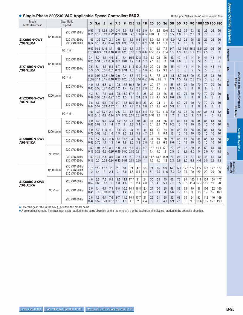
B-95Dimensions B-103 Connection and Operation B-111 Motor and Gearhead Combinations B-115Dimensions B-103 Connection and Operation B-111 Motor and Gearhead Combinations B-115
Sp
eedC
on
trolS
ystems
Bru
shless D
C M
oto
r System
sDC
Inp
ut
AC
Inp
ut
AC
Mo
tor S
ystems
BX
FBL2
AX
UA
XH
BH
FES
US
Introduction
Before Using aSpeed Control
System Single-Phase 220/230 VAC Applicable Speed Controller: ES02
ModelMotor/Gearhead
Gear RatioSpeed 3 3.6 5 6 7.5 9 12.5 15 18 25 30 36 50 60 75 90 100 120 150 180
2IK6RGN-CWE/2GNKA
1200 r/min230 VAC 50 Hz 0.97
0.111.150.13
1.680.19
1.940.22
2.40.28
3.00.34
4.10.47
4.90.56
5.90.67
7.40.84
8.81
10.61.2
13.21.5
15.91.8
202.3
232.7
263
263
263
263
220 VAC 60 Hz230 VAC 60 Hz
1.060.12
1.320.15
1.770.2
2.10.24
2.60.3
3.10.36
4.50.51
5.30.61
6.40.73
8.00.91
9.71.1
11.51.3
15.01.7
17.72
222.5
263
263
263
263
263
90 r/min 0.690.078
0.820.093
1.150.13
1.410.16
1.680.19
2.00.23
2.80.32
3.40.39
4.10.47
5.10.58
6.10.7
7.40.84
9.71.1
11.51.3
14.11.6
16.81.9
18.52.1
222.5
263
263
3IK15RGN-CWE/3GNKA
1200 r/min230 VAC 50 Hz 2.4
0.283.00.34
4.10.47
4.90.56
6.10.7
7.40.84
10.61.2
12.31.4
15.01.7
18.52.1
222.5
263
333.8
404.6
445
445
445
445
445
445
230 VAC 60 Hz 2.60.3
3.10.36
4.50.51
5.30.61
6.70.76
8.00.91
11.51.3
13.21.5
15.91.8
202.3
232.7
293.3
364.1
445
445
445
445
445
445
445
90 r/min 0.810.092
0.970.11
1.320.15
1.590.18
2.00.23
2.40.28
3.30.38
4.00.46
4.80.55
6.10.69
7.30.83
8.81
11.51.3
13.21.5
16.81.9
202.3
222.5
263
333.8
394.5
4IK25RGN-CWE/4GNKA
1200 r/min
220 VAC 60 Hz 4.00.46
4.80.55
6.80.77
8.10.92
10.61.2
12.31.4
16.81.9
202.3
242.8
303.5
374.2
445
556.3
667.5
708
708
708
708
708
708
230 VAC 50 Hz
230 VAC 60 Hz
4.30.49
5.10.58
7.10.81
8.50.97
10.61.2
13.21.5
17.72
212.4
252.9
323.7
384.4
465.3
586.6
697.9
708
708
708
708
708
708
3.80.44
4.60.52
6.40.73
7.60.87
9.71.1
11.51.3
15.91.8
19.42.2
232.6
293.3
343.9
414.7
525.9
627.1
708
708
708
708
708
708
90 r/min 1.060.12
1.320.15
1.770.2
2.10.24
2.60.3
3.10.36
4.50.51
5.30.61
6.40.73
8.00.91
9.71.1
11.51.3
15.01.7
17.72
222.5
263
293.3
354
445
525.9
5IK40RGN-CWE/5GNKA
1200 r/min
220 VAC 60 Hz 6.00.68
7.20.82
9.71.1
12.31.4
15.01.7
17.72
242.8
303.4
364.1
455.1
536.1
657.4
819.2
8810
8810
8810
8810
8810
8810
8810
230 VAC 50 Hz
230 VAC 60 Hz
6.90.78
8.20.93
11.51.3
14.11.6
16.81.9
202.3
283.2
343.9
414.7
515.8
617
748.4
8810
8810
8810
8810
8810
8810
8810
8810
5.50.63
6.70.76
9.71.1
11.51.3
14.11.6
16.81.9
232.6
283.2
333.8
414.7
505.7
606.8
768.6
8810
8810
8810
8810
8810
8810
8810
90 r/min220 VAC 60 Hz 1.59
0.181.940.22
2.60.3
3.10.36
4.00.46
4.80.55
6.70.76
8.00.91
9.71.1
12.31.4
14.11.6
17.72
222.5
263
323.7
394.5
445
525.9
657.4
788.9
230 VAC 50 Hz230 VAC 60 Hz
1.500.17
1.770.2
2.40.28
3.00.34
3.80.43
4.50.51
6.20.71
7.50.85
8.81
11.51.3
13.21.5
15.91.8
202.3
242.8
303.5
374.2
404.6
485.5
616.9
738.3
5IK60RGU-CWE/5GUKA
90 r/min
230 VAC 50 Hz220 VAC 60 Hz230 VAC 60 Hz
10.61.2
12.31.4
17.72
212.4
263
313.6
394.5
475.4
566.4
718.1
859.7
10211.6
14316.2
17119.4
17720
17720
17720
17720
17720
17720
220 VAC 60 Hz 4.60.52
5.50.63
7.60.87
8.81
11.51.3
14.11.6
17.72
212.4
242.8
303.5
384.3
455.1
627.1
758.5
849.5
10011.4
11212.7
13415.2
16819
17720
230 VAC 50 Hz
230 VAC 60 Hz
3.60.41
4.40.5
6.10.69
7.30.83
8.81
10.61.2
14.11.6
16.81.9
19.42.2
242.8
303.4
354
495.6
596.7
667.5
799
8810
10612
13215
16018.1
3.80.44
4.60.52
6.40.73
7.60.87
9.71.1
11.51.3
14.11.6
17.72
212.4
263
313.6
384.3
525.9
627.1
708
849.6
9310.6
11212.7
14015.9
16919.1
Unit=Upper Values: lb-in/Lower Values: Nm
Enter the gear ratio in the box () within the model name. A colored background indicates gear shaft rotation in the same direction as the motor shaft; a white background indicates rotation in the opposite direction.
1200 r/min
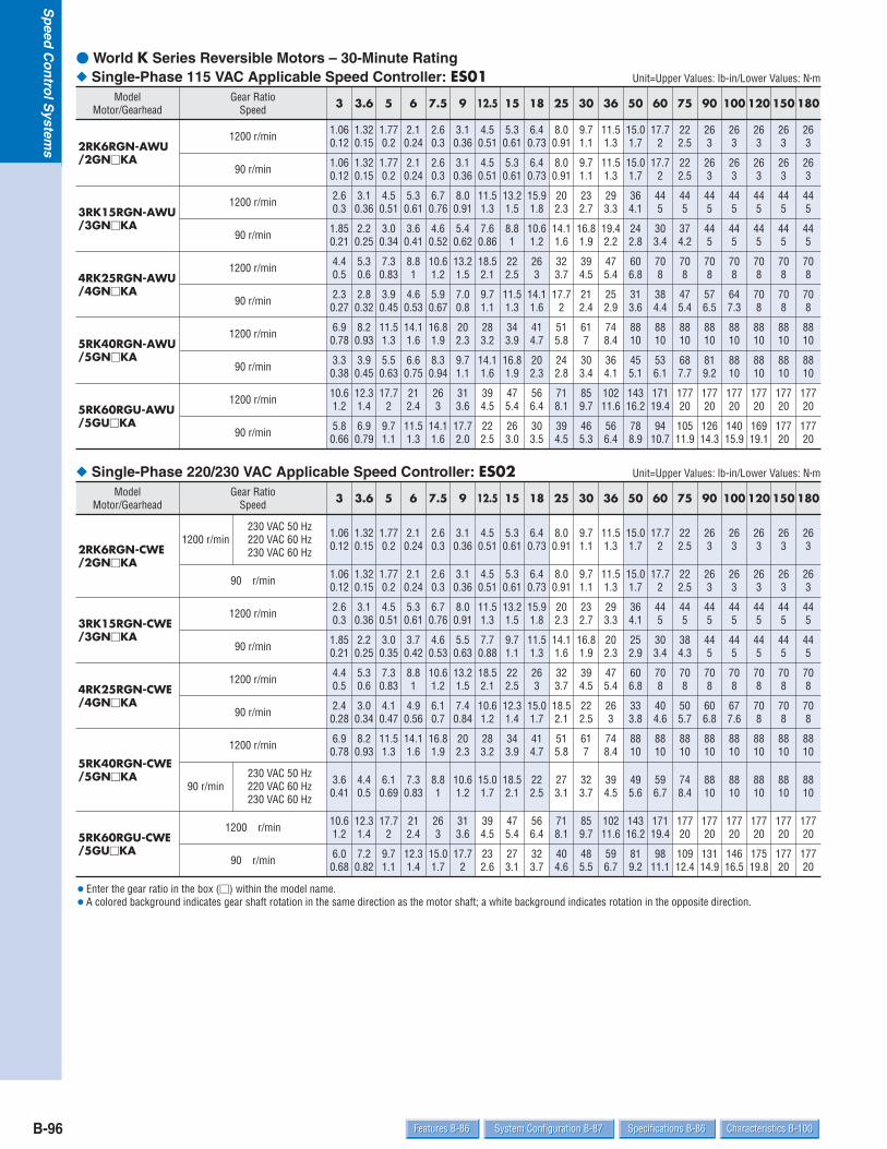
B-96 Specifications B-86 Characteristics B-100System Configuration B-87Features B-86 Specifications B-86 Characteristics B-100System Configuration B-87Features B-86
Sp
eedC
on
trolS
ystems
World K Series Reversible Motors – 30-Minute Rating Single-Phase 115 VAC Applicable Speed Controller: ES01
Single-Phase 220/230 VAC Applicable Speed Controller: ES02
ModelMotor/Gearhead
Gear RatioSpeed 3 3.6 5 6 7.5 9 12.5 15 18 25 30 36 50 60 75 90 100 120 150 180
2RK6RGN-AWU/2GNKA
1200 r/min 1.060.12
1.320.15
1.770.2
2.10.24
2.60.3
3.10.36
4.50.51
5.30.61
6.40.73
8.00.91
9.71.1
11.51.3
15.01.7
17.72
222.5
263
263
263
263
263
90 r/min 1.060.12
1.320.15
1.770.2
2.10.24
2.60.3
3.10.36
4.50.51
5.30.61
6.40.73
8.00.91
9.71.1
11.51.3
15.01.7
17.72
222.5
263
263
263
263
263
3RK15RGN-AWU/3GNKA
1200 r/min 2.60.3
3.10.36
4.50.51
5.30.61
6.70.76
8.00.91
11.51.3
13.21.5
15.91.8
202.3
232.7
293.3
364.1
445
445
445
445
445
445
445
90 r/min 1.850.21
2.20.25
3.00.34
3.60.41
4.60.52
5.40.62
7.60.86
8.81
10.61.2
14.11.6
16.81.9
19.42.2
242.8
303.4
374.2
445
445
445
445
445
4RK25RGN-AWU/4GNKA
1200 r/min 4.40.5
5.30.6
7.30.83
8.81
10.61.2
13.21.5
18.52.1
222.5
263
323.7
394.5
475.4
606.8
708
708
708
708
708
708
708
90 r/min 2.30.27
2.80.32
3.90.45
4.60.53
5.90.67
7.00.8
9.71.1
11.51.3
14.11.6
17.72
212.4
252.9
313.6
384.4
475.4
576.5
647.3
708
708
708
5RK40RGN-AWU/5GNKA
1200 r/min 6.90.78
8.20.93
11.51.3
14.11.6
16.81.9
202.3
283.2
343.9
414.7
515.8
617
748.4
8810
8810
8810
8810
8810
8810
8810
8810
90 r/min 3.30.38
3.90.45
5.50.63
6.60.75
8.30.94
9.71.1
14.11.6
16.81.9
202.3
242.8
303.4
364.1
455.1
536.1
687.7
819.2
8810
8810
8810
8810
5RK60RGU-AWU/5GUKA
1200 r/min 10.61.2
12.31.4
17.72
212.4
263
313.6
394.5
475.4
566.4
718.1
859.7
10211.6
14316.2
17119.4
17720
17720
17720
17720
17720
17720
90 r/min 5.80.66
6.90.79
9.71.1
11.51.3
14.11.6
17.72.0
222.5
263.0
303.5
394.5
465.3
566.4
788.9
9410.7
10511.9
12614.3
14015.9
16919.1
17720
17720
ModelMotor/Gearhead
Gear RatioSpeed 3 3.6 5 6 7.5 9 12.5 15 18 25 30 36 50 60 75 90 100 120 150 180
2RK6RGN-CWE/2GNKA
1200 r/min230 VAC 50 Hz220 VAC 60 Hz230 VAC 60 Hz
1.060.12
1.320.15
1.770.2
2.10.24
2.60.3
3.10.36
4.50.51
5.30.61
6.40.73
8.00.91
9.71.1
11.51.3
15.01.7
17.72
222.5
263
263
263
263
263
90 r/min 1.060.12
1.320.15
1.770.2
2.10.24
2.60.3
3.10.36
4.50.51
5.30.61
6.40.73
8.00.91
9.71.1
11.51.3
15.01.7
17.72
222.5
263
263
263
263
263
3RK15RGN-CWE/3GNKA
1200 r/min 2.60.3
3.10.36
4.50.51
5.30.61
6.70.76
8.00.91
11.51.3
13.21.5
15.91.8
202.3
232.7
293.3
364.1
445
445
445
445
445
445
445
90 r/min 1.850.21
2.20.25
3.00.35
3.70.42
4.60.53
5.50.63
7.70.88
9.71.1
11.51.3
14.11.6
16.81.9
202.3
252.9
303.4
384.3
445
445
445
445
445
4RK25RGN-CWE/4GNKA
1200 r/min 4.40.5
5.30.6
7.30.83
8.81
10.61.2
13.21.5
18.52.1
222.5
263
323.7
394.5
475.4
606.8
708
708
708
708
708
708
708
90 r/min 2.40.28
3.00.34
4.10.47
4.90.56
6.10.7
7.40.84
10.61.2
12.31.4
15.01.7
18.52.1
222.5
263
333.8
404.6
505.7
606.8
677.6
708
708
708
5RK40RGN-CWE/5GNKA
1200 r/min 6.90.78
8.20.93
11.51.3
14.11.6
16.81.9
202.3
283.2
343.9
414.7
515.8
617
748.4
8810
8810
8810
8810
8810
8810
8810
8810
90 r/min230 VAC 50 Hz220 VAC 60 Hz230 VAC 60 Hz
3.60.41
4.40.5
6.10.69
7.30.83
8.81
10.61.2
15.01.7
18.52.1
222.5
273.1
323.7
394.5
495.6
596.7
748.4
8810
8810
8810
8810
8810
5RK60RGU-CWE/5GUKA
1200 r/min 10.61.2
12.31.4
17.72
212.4
263
313.6
394.5
475.4
566.4
718.1
859.7
10211.6
14316.2
17119.4
17720
17720
17720
17720
17720
17720
90 r/min 6.00.68
7.20.82
9.71.1
12.31.4
15.01.7
17.72
232.6
273.1
323.7
404.6
485.5
596.7
819.2
9811.1
10912.4
13114.9
14616.5
17519.8
17720
17720
Unit=Upper Values: lb-in/Lower Values: Nm
Unit=Upper Values: lb-in/Lower Values: Nm
Enter the gear ratio in the box () within the model name. A colored background indicates gear shaft rotation in the same direction as the motor shaft; a white background indicates rotation in the opposite direction.

B-97Dimensions B-103 Connection and Operation B-111 Motor and Gearhead Combinations B-115Dimensions B-103 Connection and Operation B-111 Motor and Gearhead Combinations B-115
Sp
eedC
on
trolS
ystems
Bru
shless D
C M
oto
r System
sDC
Inp
ut
AC
Inp
ut
AC
Mo
tor S
ystems
BX
FBL2
AX
UA
XH
BH
FES
US
Introduction
Before Using aSpeed Control
System V Series Induction Motors – Continuous Rating Single-Phase 115 VAC Applicable Speed Controller: ES01
ModelCombination Type
Gear RatioSpeed 5 6 9 15 18 30 36 60 90 120 180 300 360
VSI206A-U1200 r/min 2.0
0.232.30.27
3.60.41
6.00.68
7.10.81
11.51.3
13.21.5
232.6
343.9
465.2
536
536
536
90 r/min 1.410.16
1.680.19
2.40.28
4.10.47
5.00.57
7.90.9
9.71.1
15.91.8
232.7
313.6
455.1
536
536
VSI315A-U1200 r/min 4.9
0.566.00.68
8.81.0
15.01.7
17.72.0
283.2
343.9
576.5
859.7
8810
8810
8810
8810
90 r/min 1.680.19
2.00.23
3.00.34
5.00.57
6.00.68
9.71.1
11.51.3
19.42.2
293.3
384.3
536.1
8810
8810
VSI425A-U1200 r/min 7.3
0.838.81.0
13.21.5
222.5
263.0
424.8
505.7
849.5
12614.3
14116
14116
14116
14116
90 r/min 2.00.23
2.30.27
3.60.41
6.00.68
7.10.81
11.51.3
13.21.5
232.6
343.9
465.2
647.3
10712.2
12914.6
VSI540A-U1200 r/min 8.8
1.010.61.2
15.91.8
263.0
313.6
515.8
617.0
10211.6
15317.4
19321.9
26030
26030 —
90 r/min 2.60.3
3.10.36
4.70.54
7.90.9
9.71.1
15.01.7
18.52.1
303.5
465.2
576.5
869.8
14416.3 —
VSI560A-U1200 r/min 19.4
2.2232.6
354.0
586.6
697.9
11112.6
13415.2
22025.3
26030
26030
26030
26030 —
90 r/min 8.40.95
9.71.1
15.01.7
242.8
303.4
475.4
576.5
9510.8
14416.3
18020.4
26030
26030 —
VSI590A-U1200 r/min 29
3.3343.9
525.9
879.9
10011.3
16618.8
20022.6
33037.7
35040
35040
35040 — —
90 r/min 8.40.95
9.71.1
15.01.7
242.8
293.3
475.4
576.5
9510.8
13515.3
18020.4
27030.6 — —
Unit=Upper Values: lb-in/Lower Values: Nm
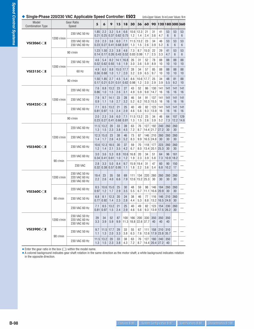
B-98 Specifications B-86 Characteristics B-100System Configuration B-87Features B-86 Specifications B-86 Characteristics B-100System Configuration B-87Features B-86
Sp
eedC
on
trolS
ystems
Single-Phase 220/230 VAC Applicable Speed Controller: ES02Model
Combination TypeGear Ratio
Speed 5 6 9 15 18 30 36 60 90 120 180 300 360
VSI206C-E1200 r/min
230 VAC 50 Hz 1.850.21
2.20.25
3.20.37
5.40.62
6.60.75
10.61.2
12.31.4
212.4
313.6
414.7
536
536
536
220 VAC 60 Hz230 VAC 60 Hz
2.00.23
2.30.27
3.60.41
6.00.68
7.10.81
11.51.3
13.21.5
232.6
343.9
465.2
536
536
536
90 r/min 1.230.14
1.500.17
2.30.26
3.80.43
4.60.52
7.30.83
8.70.99
15.01.7
222.5
293.3
414.7
536
536
VSI315C-E1200 r/min
230 VAC 50 Hz 4.60.52
5.40.62
8.20.93
14.11.6
16.81.9
263.0
313.6
525.9
788.9
8810
8810
8810
8810
60 Hz 4.90.56
6.00.68
8.81.0
15.01.7
17.72.0
283.2
343.9
576.5
859.7
8810
8810
8810
8810
90 r/min 1.500.17
1.850.21
2.70.31
4.50.51
5.40.62
8.60.98
10.61.2
17.72.0
252.9
343.9
485.5
819.2
8810
VSI425C-E1200 r/min
220 VAC 60 Hz 7.60.86
8.81.0
13.21.5
232.6
273.1
434.9
525.9
869.8
13014.7
14116
14116
14116
14116
230 VAC 50 Hz
230 VAC 60 Hz
7.90.9
9.71.1
14.11.6
232.7
283.2
465.2
546.2
9110.3
13715.5
14116
14116
14116
14116
7.10.81
8.50.97
13.21.5
212.4
252.9
404.6
495.6
829.3
12313.9
14116
14116
14116
14116
90 r/min 2.00.23
2.30.27
3.60.41
6.00.68
7.10.81
11.51.3
13.21.5
232.6
343.9
465.2
647.3
10712.2
12914.6
VSI540C-E
1200 r/min
220 VAC 60 Hz 11.51.3
13.21.5
202.3
333.8
394.5
637.2
768.7
12714.4
19221.7
24027.2
26030
26030 —
230 VAC 50 Hz
230 VAC 60 Hz
12.31.4
15.01.7
232.6
384.3
465.2
738.3
879.9
14616.5
21024.8
26030
26030
26030 —
10.61.2
12.31.4
18.52.1
303.5
374.2
596.7
708.0
11813.4
17720.1
22325.3
26030
26030 —
90 r/min220 VAC 60 Hz 3.0
0.343.60.41
5.30.61
8.81.0
10.61.2
16.81.9
202.3
343.9
515.8
647.3
9610.9
16118.2 —
230 VAC 2.80.32
3.30.38
5.00.57
8.40.95
9.71.1
15.91.8
19.42.2
313.6
475.4
606.8
9010.2
15017 —
VSI560C-E
1200 r/min230 VAC 50 Hz220 VAC 60 Hz230 VAC 60 Hz
19.42.2
232.6
354.0
586.6
697.9
11112.6
13415.2
22025.3
26030
26030
26030
26030 —
90 r/min
220 VAC 60 Hz 8.50.97
10.61.2
15.01.7
252.9
303.5
485.5
596.7
9811.1
14616.6
18420.9
26030
26030 —
230 VAC 50 Hz
230 VAC 60 Hz
6.80.77
8.10.92
12.31.4
202.3
242.8
384.4
465.3
778.8
11613.2
14616.5
21024.8
26030 —
7.10.81
8.50.97
13.21.5
212.4
252.9
404.6
495.6
829.3
12313.9
15417.5
23026.2
26030 —
VSI590C-E
1200 r/min230 VAC 50 Hz220 VAC 60 Hz230 VAC 60 Hz
293.3
343.9
525.9
879.9
10011.3
16618.8
20022.6
33037.7
35040
35040
35040 — —
90 r/min230 VAC 50 Hz
230 VAC 60 Hz
9.71.1
11.51.3
17.72.0
293.3
333.8
556.3
677.6
11112.6
15817.9
21023.8
31035.7 — —
11.51.3
13.21.5
202.3
333.8
384.3
637.2
768.7
12714.4
18020.4
24027.2
35040 — —
Unit=Upper Values: lb-in/Lower Values: Nm
Enter the gear ratio in the box () within the model name. A colored background indicates gear shaft rotation in the same direction as the motor shaft; a white background indicates rotation
in the opposite direction.
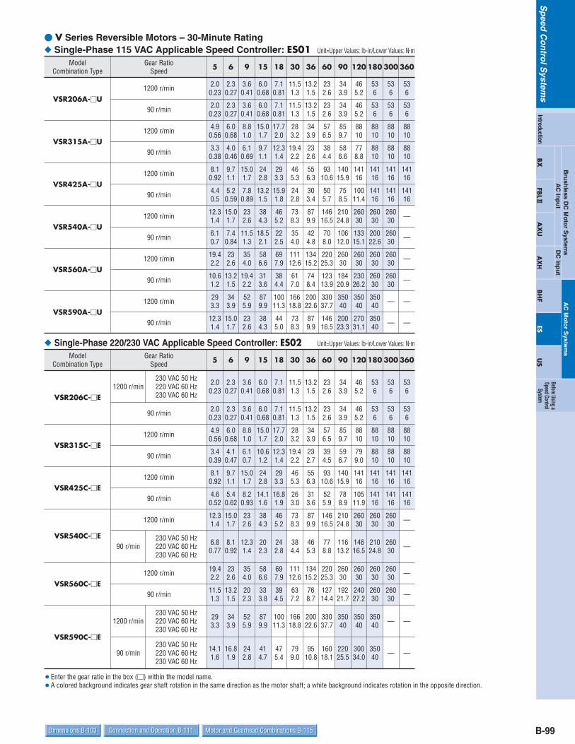
B-99Dimensions B-103 Connection and Operation B-111 Motor and Gearhead Combinations B-115Dimensions B-103 Connection and Operation B-111 Motor and Gearhead Combinations B-115
Sp
eedC
on
trolS
ystems
Bru
shless D
C M
oto
r System
sDC
Inp
ut
AC
Inp
ut
AC
Mo
tor S
ystems
BX
FBL2
AX
UA
XH
BH
FES
US
Introduction
Before Using aSpeed Control
System V Series Reversible Motors – 30-Minute Rating Single-Phase 115 VAC Applicable Speed Controller: ES01
Single-Phase 220/230 VAC Applicable Speed Controller: ES02
ModelCombination Type
Gear RatioSpeed 5 6 9 15 18 30 36 60 90 120 180 300 360
VSR206A-U1200 r/min 2.0
0.232.30.27
3.60.41
6.00.68
7.10.81
11.51.3
13.21.5
232.6
343.9
465.2
536
536
536
90 r/min 2.00.23
2.30.27
3.60.41
6.00.68
7.10.81
11.51.3
13.21.5
232.6
343.9
465.2
536
536
536
VSR315A-U1200 r/min 4.9
0.566.00.68
8.81.0
15.01.7
17.72.0
283.2
343.9
576.5
859.7
8810
8810
8810
8810
90 r/min 3.30.38
4.00.46
6.10.69
9.71.1
12.31.4
19.42.2
232.6
384.4
586.6
778.8
8810
8810
8810
VSR425A-U1200 r/min 8.1
0.929.71.1
15.01.7
242.8
293.3
465.3
556.3
9310.6
14015.9
14116
14116
14116
14116
90 r/min 4.40.5
5.20.59
7.80.89
13.21.5
15.91.8
242.8
303.4
505.7
758.5
10011.4
14116
14116
14116
VSR540A-U1200 r/min 12.3
1.415.01.7
232.6
384.3
465.2
738.3
879.9
14616.5
21024.8
26030
26030
26030 —
90 r/min 6.10.7
7.40.84
11.51.3
18.52.1
222.5
354.0
424.8
708.0
10612.0
13315.1
20022.6
26030 —
VSR560A-U1200 r/min 19.4
2.2232.6
354.0
586.6
697.9
11112.6
13415.2
22025.3
26030
26030
26030
26030 —
90 r/min 10.61.2
13.21.5
19.42.2
313.6
384.4
617.0
748.4
12313.9
18420.9
23026.2
26030
26030 —
VSR590A-U1200 r/min 29
3.3343.9
525.9
879.9
10011.3
16618.8
20022.6
33037.7
35040
35040
35040 — —
90 r/min 12.31.4
15.01.7
232.6
384.3
445.0
738.3
879.9
14616.5
20023.3
27031.1
35040 — —
ModelCombination Type
Gear RatioSpeed 5 6 9 15 18 30 36 60 90 120 180 300 360
VSR206C-E1200 r/min
230 VAC 50 Hz220 VAC 60 Hz230 VAC 60 Hz
2.00.23
2.30.27
3.60.41
6.00.68
7.10.81
11.51.3
13.21.5
232.6
343.9
465.2
536
536
536
90 r/min 2.00.23
2.30.27
3.60.41
6.00.68
7.10.81
11.51.3
13.21.5
232.6
343.9
465.2
536
536
536
VSR315C-E1200 r/min 4.9
0.566.00.68
8.81.0
15.01.7
17.72.0
283.2
343.9
576.5
859.7
8810
8810
8810
8810
90 r/min 3.40.39
4.10.47
6.10.7
10.61.2
12.31.4
19.42.2
232.7
394.5
596.7
799.0
8810
8810
8810
VSR425C-E1200 r/min 8.1
0.929.71.1
15.01.7
242.8
293.3
465.3
556.3
9310.6
14015.9
14116
14116
14116
14116
90 r/min 4.60.52
5.40.62
8.20.93
14.11.6
16.81.9
263.0
313.6
525.9
788.9
10511.9
14116
14116
14116
VSR540C-E
1200 r/min 12.31.4
15.01.7
232.6
384.3
465.2
738.3
879.9
14616.5
21024.8
26030
26030
26030 —
90 r/min230 VAC 50 Hz220 VAC 60 Hz230 VAC 60 Hz
6.80.77
8.10.92
12.31.4
202.3
242.8
384.4
465.3
778.8
11613.2
14616.5
21024.8
26030 —
VSR560C-E1200 r/min 19.4
2.2232.6
354.0
586.6
697.9
11112.6
13415.2
22025.3
26030
26030
26030
26030 —
90 r/min 11.51.3
13.21.5
202.3
333.8
394.5
637.2
768.7
12714.4
19221.7
24027.2
26030
26030 —
VSR590C-E
1200 r/min230 VAC 50 Hz220 VAC 60 Hz230 VAC 60 Hz
293.3
343.9
525.9
879.9
10011.3
16618.8
20022.6
33037.7
35040
35040
35040 — —
90 r/min230 VAC 50 Hz220 VAC 60 Hz230 VAC 60 Hz
14.11.6
16.81.9
242.8
414.7
475.4
799.0
9510.8
16018.1
22025.5
30034.0
35040 — —
Unit=Upper Values: lb-in/Lower Values: Nm
Unit=Upper Values: lb-in/Lower Values: Nm
Enter the gear ratio in the box () within the model name. A colored background indicates gear shaft rotation in the same direction as the motor shaft; a white background indicates rotation in the opposite direction.

B-100 Specifications B-86 Characteristics B-100System Configuration B-87Features B-86 Specifications B-86 Characteristics B-100System Configuration B-87Features B-86
Sp
eedC
on
trolS
ystems
Gearmotor — Torque Table when a Right-Angle Gearhead is AttachedRight-Angle Gearhead is available for World K Series.Page A-196
Permissible Overhung Load and Permissible Thrust LoadMotor (Round shaft type)Page A-11GearheadPage A-11
Permissible Load Inertia J for GearheadPage A-12
Speed — Torque Characteristics Induction MotorsEnter the gear ratio in the box () within the V Series combination type model name. The characteristics of V Series are formotor’s only.
15001000500 1800
Speed [r/min]
Torq
ue [o
z-in
]
Torq
ue [m
Nm
]
0
20
40
60
80
100
0
2
4
6
8
10
12
14110/115 VACSafe-Operation Line
2IK6RGN-AWU2IK6RA-AWU ES01VSI206A-U
Permissible Torque when Gearhead is Attached
110 VAC115 VAC
15001000500 1800
3IK15RGN-AWU3IK15RA-AWU ES01VSI315A-U
Speed [r/min]
110/115 VAC Safe-Operation Line
Permissible Torque when Gearhead is Attached
110 VAC115 VAC
Torq
ue [o
z-in
]
Torq
ue [m
Nm
]
0
40
80
120
160
200
240
0
5
10
15
20
25
30
35
15001000500 1800
Speed [r/min]
Torq
ue [o
z-in
]
Torq
ue [N
m]
0
0.1
0.2
0.3
0.4
0.5
0
10
20
30
40
50
60
70
4IK25RGN-AWU4IK25RA-AWU ES01VSI425A-U
110 VAC115 VAC
Permissible Torque when Gearhead is Attached
110/115 VAC Safe-Operation Line
15001000500 1800
5IK40RGN-AWU5IK40RA-AWU ES01VSI540A-U
110 VAC 115 VAC
Speed [r/min]
Permissible Torque when Gearhead is Attached
110/115 VAC Safe-Operation Line
Torq
ue [o
z-in
]
Torq
ue [N
m]
0
0.1
0.2
0.3
0.4
0.5
0
10
20
30
40
50
60
70
15001000500 1800
Speed [r/min]
Torq
ue [o
z-in
]
Torq
ue [N
m]
0
0.2
0.4
0.6
0.8
1.0
0
25
50
75
100
125
110 VAC 115 VAC
110/115 VACSafe-Operation Line
Permissible Torque when Gearhead is Attached
5IK60RGU-AWU ES015IK60RA-AWUVSI560A-U
15001000500 1800
Permissible Torque whenGearhead is Attached
110/115 VAC Safe-Operation Line
110 VAC115 VAC
Speed [r/min]
Torq
ue [o
z-in
]
Torq
ue [N
m]
0
0.2
0.4
0.6
0.8
1.0
0
25
50
75
100
125
VSI590A-U ES01

B-101Dimensions B-103 Connection and Operation B-111 Motor and Gearhead Combinations B-115Dimensions B-103 Connection and Operation B-111 Motor and Gearhead Combinations B-115
Sp
eedC
on
trolS
ystems
Bru
shless D
C M
oto
r System
sDC
Inp
ut
AC
Inp
ut
AC
Mo
tor S
ystems
BX
FBL2
AX
UA
XH
BH
FES
US
Introduction
Before Using aSpeed Control
System
15001000500 1800Speed [r/min]
Torq
ue [o
z-in
]
Torq
ue [m
Nm
]
0
20
40
60
80
100
0
2
4
6
8
10
12
14
50 Hz Safe-Operation Line
2IK6RGN-CWE2IK6RA-CWE ES02VSI206C-E
60 HzSafe-Operation Line
Permissible Torque when Gearhead is Attached
230 VAC 50 Hz230 VAC 60 Hz
220 VAC 60 Hz220 VAC 50 Hz
15001000500 1800Speed [r/min]
Torq
ue [o
z-in
]
Torq
ue [m
Nm
]
0
40
80
120
160
200
0
5
10
15
20
25
50 Hz Safe-Operation Line
3IK15RGN-CWE3IK15RA-CWE ES02VSI315C-E
60 HzSafe-Operation Line
Permissible Torque when Gearhead is Attached
230 VAC 50 Hz230 VAC 60 Hz
220 VAC 60 Hz220 VAC 50 Hz
15001000500 1800Speed [r/min]
Torq
ue [o
z-in
]
Torq
ue [N
m]
0
0.1
0.2
0.3
0.4
0.5
0
10
20
30
40
50
60
70
4IK25RGN-CWE4IK25RA-CWE ES02VSI425C-E
50 HzSafe-Operation Line
60 HzSafe-Operation Line
Permissible Torque when Gearhead is Attached
230 VAC 50 Hz230 VAC 60 Hz
220 VAC 60 Hz220 VAC 50 Hz
15001000500 1800Speed [r/min]
Torq
ue [o
z-in
]
Torq
ue [N
m]
0
0.1
0.2
0.3
0.4
0.5
0
10
20
30
40
50
60
70
5IK40RGN-CWE5IK40RA-CWE ES02VSI540C-E
Permissible Torque when Gearhead is Attached
50 Hz Safe-Operation Line60 Hz Safe-Operation Line
230 VAC 50 Hz230 VAC 60 Hz
220 VAC 60 Hz220 VAC 50 Hz
15001000500 1800Speed [r/min]
Torq
ue [o
z-in
]
Torq
ue [N
m]
0
0.2
0.4
0.6
0.8
1.0
0
25
50
75
100
125
5IK60RGU-CWE5IK60RA-CWE ES02VSI560C-E
230 VAC, 60 Hz Safe-Operation Line
Permissible Torque when Gearhead is Attached
220 VAC, 60 HzSafe-Operation Line
220/230 VAC, 50 HzSafe-Operation Line
230 VAC 50 Hz230 VAC 60 Hz
220 VAC 60 Hz220 VAC 50 Hz
15001000500 1800
50 Hz Safe-Operation Line
Permissible Torque when Gearhead is Attached 60 Hz Safe-Operation Line
Speed [r/min]
Torq
ue [o
z-in
]
Torq
ue [N
m]
0
0.2
0.4
0.6
0.8
1.0
1.2
0
25
50
100
75
125
150
230 VAC 50 Hz230 VAC 60 Hz
220 VAC 60 Hz220 VAC 50 Hz
VSI590C-E ES02
15001000500 1800Speed [r/min]
Torq
ue [o
z-in
]
Torq
ue [m
Nm
]
0
20
40
60
80
100
120
0
2
4
6
8
10
12
14
16
2RK6RGN-AWU2RK6RA-AWU ES01VSR206A-U
110 VAC115 VAC
110/115 VAC Safe-Operation Line
Permissible Torque when Gearhead is Attached
15001000500 1800
3RK15RGN-AWU3RK15RA-AWU ES01VSR315A-U
110 VAC115 VAC
Speed [r/min]
110/115 VACSafe-Operation Line
Permissible Torque when Gearhead is Attached
Torq
ue [o
z-in
]
Torq
ue [N
m]
0
40
80
120
160
200
240
0
5
10
15
20
25
30
35
Reversible Motors

B-102 Specifications B-86 Characteristics B-100System Configuration B-87Features B-86 Specifications B-86 Characteristics B-100System Configuration B-87Features B-86
Sp
eedC
on
trolS
ystems
15001000500 1800
4RK25RGN-AWU4RK25RA-AWU ES01VSR425A-U
110 VAC115 VAC
Speed [r/min]
110/115 VAC Safe-Operation Line
Permissible Torque when Gearhead is Attached
Torq
ue [o
z-in
]
Torq
ue [N
m]
0
0.1
0.2
0.3
0.4
0.5
0
10
20
30
40
50
60
70
15001000500 1800
5RK40RGN-AWU5RK40RA-AWU ES01VSR540A-U
110 VAC 115 VAC
Speed [r/min]
110/115 VAC Safe-Operation Line
Permissible Torque when Gearhead is Attached
Torq
ue [o
z-in
]
Torq
ue [N
m]
0
0.1
0.2
0.3
0.4
0.5
0.6
0
10
20
30
40
50
60
70
80
15001000500 1800
5RK60RGU-AWU5RK60RA-AWU ES01VSR560A-U
110 VAC 115 VAC
Speed [r/min]
115 VAC Safe-Operation Line
110 VAC Safe-Operation LinePermissible Torque when Gearhead is Attached
Torq
ue [o
z-in
]
Torq
ue [N
m]
0
0.2
0.4
0.6
0.8
1.0
1.2
0
25
50
75
100
125
150
15001000500 1800
Permissible Torque when Gearhead is Attached
110/115 VAC Safe-Operation Line
Speed [r/min]
110 VAC115 VAC
Torq
ue [o
z-in
]
Torq
ue [N
m]
0
0.2
0.4
0.6
0.8
1.0
1.2
0
25
50
75
100
125
150
VSR590A-U ES01
15001000500 1800Speed [r/min]
230 VAC 50 Hz230 VAC 60 Hz
220 VAC 60 Hz220 VAC 50 Hz
Torq
ue [o
z-in
]
Torq
ue [m
Nm
]
0
20
40
60
80
100
0
2
4
6
8
10
12
14
2RK6RGN-CWE2RK6RA-CWE ES02VSR206C-E
Permissible Torque when Gearhead is Attached
230 VAC 60 HzSafe-Operation Line
230 VAC 50 HzSafe-Operation Line
15001000500 1800Speed [r/min]
Torq
ue [o
z-in
]
Torq
ue [m
Nm
]
0
40
80
120
160
200
240
0
5
10
15
20
25
30
35
3RK15RGN-CWE3RK15RA-CWE ES02VSR315C-E
60 HzSafe-Operation Line
Permissible Torque when Gearhead is Attached
50 Hz Safe-Operation Line
230 VAC 50 Hz230 VAC 60 Hz
220 VAC 60 Hz220 VAC 50 Hz
15001000500 1800Speed [r/min]
Torq
ue [o
z-in
]
Torq
ue [N
m]
0
0.1
0.2
0.3
0.4
0
10
20
30
40
50
4RK25RGN-CWE4RK25RA-CWE ES02VSR425C-E
50 HzSafe-Operation Line
60 Hz Safe-Operation Line Permissible Torque when Gearhead is Attached
230 VAC 50 Hz230 VAC 60 Hz
220 VAC 60 Hz220 VAC 50 Hz
15001000500 1800Speed [r/min]
Torq
ue [o
z-in
]
Torq
ue [N
m]
0
0.1
0.2
0.3
0.4
0.5
0.6
0
10
20
30
40
50
60
70
80
5RK40RGN-CWE5RK40RA-CWE ES02VSR540C-E
Permissible Torque when Gearhead isAttached
50 Hz Safe-Operation Line
60 Hz Safe-Operation Line
230 VAC 50 Hz230 VAC 60 Hz
220 VAC 60 Hz220 VAC 50 Hz
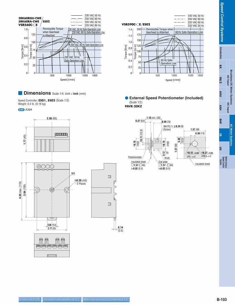
B-103Dimensions B-103 Connection and Operation B-111 Motor and Gearhead Combinations B-115Dimensions B-103 Connection and Operation B-111 Motor and Gearhead Combinations B-115
Sp
eedC
on
trolS
ystems
Bru
shless D
C M
oto
r System
sDC
Inp
ut
AC
Inp
ut
AC
Mo
tor S
ystems
BX
FBL2
AX
UA
XH
BH
FES
US
Introduction
Before Using aSpeed Control
System
Dimensions Scale 1/4, Unit = inch (mm)
0.37 (9.5) 0.59 (15)
0.12 ( 3
)
(Screw)
KnobDial plate1.57 (40)t=0.02 (0.5)
Insulated sheet1.57 (40)t=0.02 (0.5)
Potentiometer
1.57 (40)
0.30 (7.5)
0.49
( 12.5
)
1.57
( 40)
Insulated sheet
0.12 0.008
(3 0.2)0.370.008
(9.50.2)
1.18 min. (30)
0.
79(
20)
0.
79(
20)
M4 P0.7
0.
11 (
2.8)
0.24 (6)
2.56 (65)
1.77
(45)
0.20 (5)2 Places
3.94
(100
)
2.17 (55)
4.33
max
. (11
0)
0.66 (16.8)0.14(3.5)
M4
External Speed Potentiometer (Included) (Scale 1/2)
PAVR-20KZ
Speed Controller: ES01, ES02 (Scale 1/2)Weight: 0.4 lb. (0.18 kg)
d A394
15001000500 1800Speed [r/min]
Torq
ue [o
z-in
]
Torq
ue [N
m]
0
0.2
0.4
0.6
0.8
1.0
0
25
50
75
100
125
5RK60RGU-CWE5RK60RA-CWE ES02VSR560C-E
230 VAC, 60 Hz Safe-Operation LinePermissible Torque when Gearhead is Attached
230 VAC, 50 Hz Safe-Operation Line
220 VAC, 50 HzSafe-Operation Line
220 VAC, 60 Hz Safe-Operation Line
230 VAC 50 Hz230 VAC 60 Hz
220 VAC 60 Hz220 VAC 50 Hz
15001000500 1800
50 Hz Safe-Operation Line
Permissible Torque when Gearhead is Attached 60 Hz Safe-Operation Line
Speed [r/min]
Torq
ue [o
z-in
]
Torq
ue [N
m]
0
0.2
0.4
0.6
0.8
1.0
1.2
1.4
0
25
50
75
100
125
150
175
200
VSR590C-E ES02
230 VAC 50 Hz230 VAC 60 Hz
220 VAC 50 Hz220 VAC 60 Hz

B-104 Specifications B-86 Characteristics B-100System Configuration B-87Features B-86 Specifications B-86 Characteristics B-100System Configuration B-87Features B-86
Sp
eedC
on
trolS
ystems
World K Series Motor/Gearhead (Pinion Shaft Type) Round Shaft Type
2.760.02
(700.5)
0.94(24)0.08(2)
2.36 (60)
22 30
(60.012)00.0005
00.2362
(54
0.03
0)0
0.00
12 0
2.
1260
0.177 (4.5)4 Holes
1.26 (32)
0.12 (3)
0.39
(10)0.50
(12.7)
0.
94(
24)
0.29
3 (7
.437
)
(7.9370.015)05/16"0.0006
00.3125
2GN3KA~18KA: L = 1.18 (30)2GN25KA~180KA: L = 1.57 (40)
2.
36 (
60)
1.
85 (
47)
L0.39 (10) 2.95 (75)
0.28(7)
2 Generator Leads 12 inch (300 mm) LengthUL Style 3266, AWG 24
3 Motor Leads 12 inch (300 mm) LengthUL Style 3266, AWG 20
2.36 (60)
0.177 (4.5) 4 Holes
2230'
2.760.02
(700.5)
d A364d A065AU (2GN3KA18KA)A065BU (2GN25KA180KA)
2IK6RA-AWU2IK6RA-CWE2RK6RA-AWU2RK6RA-CWEWeight: 1.76 lb. (0.8 kg)
2GNKA
Weight: 0.88 lb. (0.4 kg)
2IK6RGN-AWU2IK6RGN-CWE2RK6RGN-AWU2RK6RGN-CWEWeight: 1.76 lb. (0.8 kg)
Motor/Gearhead (Pinion Shaft Type) Round Shaft Type
3.230.02
(820.5)
0.08(2)
1.26 (32)2.76 (70)
2230
(60.012)00.0005
00.2362
(64
0.
030)
00.
0012
0
2.51
97
0.217 (5.5)4 Holes
3 Motor Leads 12 inch (300 mm) LengthUL Style 3271, AWG 20
L
2.
72 (
69)
3.15 (80)0.28 (7)
1.
85 (
47)
0.39 (10) 1.26 (32)0.12 (3)
1.
18 (
30)
0.59
(15)0.50
(12.7) 0.34
7 (8
.825
)
2230'
0.217 (5.5) 4 Holes
2.76 (70)
3.230.02
(820.5)
2 Generator Leads 12 inch (300 mm) LengthUL Style 3266, AWG 24
3GN3KA~18KA: L = 1.26 (32)3GN25KA~180KA: L = 1.65 (42)
3/8"0(9.5250.015)
0.0006 00.3750
d A365d A066AU (3GN3KA18KA)A066BU (3GN25KA180KA)
3IK15RA-AWU3IK15RA-CWE3RK15RA-AWU3RK15RA-CWEWeight: 2.6 lb. (1.2 kg)
3GNKA
Weight: 1.21 lb. (0.55 kg)
3IK15RGN-AWU3IK15RGN-CWE3RK15RGN-AWU3RK15RGN-CWEWeight: 2.6 lb. (1.2 kg)
Decimal GearheadCan be connected to 2IK6RGN, 2RK6RGN type2GN10XK Weight: 0.44 lb. (0.2 kg)
d A0031.52 (38.5)
1.02(26)
0.49(12.5)
0.08(2)
0.177 (4.5) 4 Holes
2.76 0.02
(70 0.5)
2.36 (60)
( 54
0.
030)
0.
0012
0
0
2.
1260
Decimal GearheadCan be connected to 3IK15RGN, 3RK15RGN type3GN10XK Weight: 0.66 lb. (0.3 kg)
d A0091.69 (43)
1.18(30) 0.51 (13)0.08(2)
0.217 (5.5) 4 Holes
3.23 0.02
(82 0.5)
2.76 (70)
( 64
0.03
0)0
0.00
12 0
2.
5197
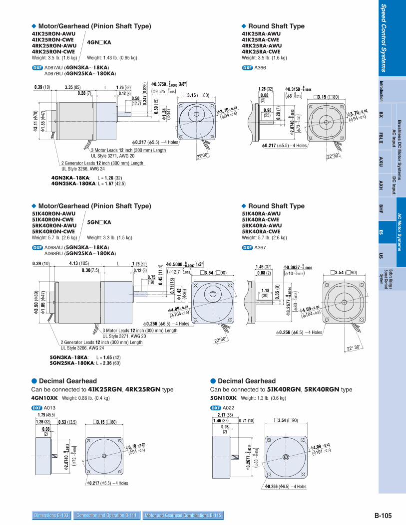
B-105Dimensions B-103 Connection and Operation B-111 Motor and Gearhead Combinations B-115Dimensions B-103 Connection and Operation B-111 Motor and Gearhead Combinations B-115
Sp
eedC
on
trolS
ystems
Bru
shless D
C M
oto
r System
sDC
Inp
ut
AC
Inp
ut
AC
Mo
tor S
ystems
BX
FBL2
AX
UA
XH
BH
FES
US
Introduction
Before Using aSpeed Control
System Motor/Gearhead (Pinion Shaft Type) Round Shaft Type
0.217 (5.5)4 Holes
3.15 (80)
0.28
(7)
1.26 (32)0.08(2)
0.98(25)
(80.015)00.0006
00.3150
(73
0.03
0)0
0.
0012
0
2.87
40
3.700.02
(940.5)
2230
L
3.
11 (
79)
3.35 (85)0.28 (7)
1.
85 (
47)
0.39 (10) 1.26 (32)
(34
)
1.340.
59 ( 1
5)
0.12 (3)0.50(12.7) 0.
347
( 8.8
25)
0(9.5250.015)
0.217 (5.5) 4 Holes
3.15 (80)
2230'
3.700.02
(940.5)
3 Motor Leads 12 inch (300 mm) LengthUL Style 3271, AWG 20
2 Generator Leads 12 inch (300 mm) LengthUL Style 3266, AWG 24
4GN3KA~18KA: L = 1.26 (32)4GN25KA~180KA: L = 1.67 (42.5)
3/8"0.0006 00.3750
d A366d A067AU (4GN3KA18KA)A067BU (4GN25KA180KA)
4IK25RA-AWU4IK25RA-CWE4RK25RA-AWU4RK25RA-CWEWeight: 3.5 lb. (1.6 kg)
4GNKA
Weight: 1.43 lb. (0.65 kg)
4IK25RGN-AWU4IK25RGN-CWE4RK25RGN-AWU4RK25RGN-CWEWeight: 3.5 lb. (1.6 kg)
Motor/Gearhead (Pinion Shaft Type) Round Shaft Type
4.090.02
(1040.5)
0.35
(9)
1.46 (37)0.08 (2) 3.54 (90)
1.18(30)
0.256 (6.5) 4 Holes
22 30
(100.015)00.0006
00.3937
(83
0.
035)
00.
0014
0
3.26
77
L
3.
50 (
89)
4.13 (105)0.30(7.5)
1.
85 (
47)
0.39 (10)0.12 (3)
1.26 (32)
0.71
(18)
1.
42(
36)
1/2"
0.45
( 11.
4)
0.75(19)
(12.70.018)0
2230'
3.54 (90)
0.256 (6.5) 4 Holes
4.090.02
(1040.5)
0.0007 00.5000
2 Generator Leads 12 inch (300 mm) LengthUL Style 3266, AWG 24
3 Motor Leads 12 inch (300 mm) LengthUL Style 3271, AWG 20
5GN3KA~18KA: L = 1.65 (42)5GN25KA~180KA: L = 2.36 (60)
d A367d A068AU (5GN3KA18KA)A068BU (5GN25KA180KA)
5IK40RA-AWU5IK40RA-CWE5RK40RA-AWU5RK40RA-CWEWeight: 5.7 lb. (2.6 kg)
5GNKA
Weight: 3.3 lb. (1.5 kg)
5IK40RGN-AWU5IK40RGN-CWE5RK40RGN-AWU5RK40RGN-CWEWeight: 5.7 lb. (2.6 kg)
Decimal GearheadCan be connected to 4IK25RGN, 4RK25RGN type4GN10XK Weight: 0.88 lb. (0.4 kg)
d A0131.79 (45.5)
1.26 (32) 0.53 (13.5)
0.08(2)
0.217 (5.5) 4 Holes
( 73
0.
030)
0.
0012
0 0
2.
8740
3.15 (80)
3.70 0.02
(94 0.5)
Decimal GearheadCan be connected to 5IK40RGN, 5RK40RGN type5GN10XK Weight: 1.3 lb. (0.6 kg)
d A022
1.46 (37) 0.71 (18)2.17 (55)
0.08(2)
3.54 (90)
0.256 (6.5) 4 Holes
(83
0.
035)
00.
0014
0
3.26
77
4.09 0.02
(104 0.5)

B-106 Specifications B-86 Characteristics B-100System Configuration B-87Features B-86 Specifications B-86 Characteristics B-100System Configuration B-87Features B-86
Sp
eedC
on
trolS
ystems
Motor/Gearhead (Pinion Shaft Type) Round Shaft Type
0.256 (6.5)4 Holes
3.54 (90)0.08 (2)
1.46 (37)
1.18(30) 0.
43 ( 1
1)
(83
0.
035)
0
(120.018)0
1.30(33)
0.
0014
0
3.26
77
0.0007 00.4724
4.090.02
(1040.5)
0.73
(18.
5)
1.65
1.
34
(42)
3.
54 (
90)
5.91 (150)0.30 (7.5)
2.56 (65)0.28 (7)
1.50 (38)
1.125(28.58)
0.71
(18)
(34
)
1.30(33)
4.090.02
(1040.5)
3.54 (90)
5/8"0.0005 00.6250
(15.8750.011)0
0.256 (6.5)4 Holes
Cable 0.44 (11.2), 20 inch (500 mm) Length3 Motor Leads: UL Style 3266, AWG 202 Generator Leads: UL Style 3266, AWG 242 Cooling Fan Leads: UL Style 3266, AWG 24
1.1250.008(28.580.2) 0(4.7630.03)
00.18750.0012
0( 4.7
63
0.03
)0
0.18
75
0.00
12
0.040(4.763 0 )
0.00160.1875 0
0.
1
0.
004
0.10
8 0
Key and Key Slot (Scale 1/2) (The key is provided with the gearhead)
(2.74
3
0
)
d A358d A069U (5GU3KA180KA)
5IK60RA-AWU5IK60RA-CWE5RK60RA-AWU5RK60RA-CWEWeight: 7.1 lb. (3.2 kg)
5GUKA
Weight: 3.3 lb. (1.5 kg)
5IK60RGU-AWU5IK60RGU-CWE5RK60RGU-AWU5RK60RGU-CWEWeight: 7.1 lb. (3.2 kg)
Decimal GearheadCan be connected to 5IK60RGU, 5RK60RGU type5GU10XKB Weight: 1.3 lb. (0.6 kg)
d A029
2.40 (61)1.57 (40)
0.08(2)
3.54 (90)
0.425 (10.8) 4 Holes
0.83 (21)
( 83
0.
035)
00.
0014
0
3.26
77
4.09 0.02
(104 0.5)

B-107Dimensions B-103 Connection and Operation B-111 Motor and Gearhead Combinations B-115Dimensions B-103 Connection and Operation B-111 Motor and Gearhead Combinations B-115
Sp
eedC
on
trolS
ystems
Bru
shless D
C M
oto
r System
sDC
Inp
ut
AC
Inp
ut
AC
Mo
tor S
ystems
BX
FBL2
AX
UA
XH
BH
FES
US
Introduction
Before Using aSpeed Control
System
Combination Type
1.85
(47
)
L
2.
36 (
60)
0.28 (7)2.95 (75)0.39 (10)
0.98 (25)
1.26 (32)0.16 (4)
0(
10
0.01
5)
0.39
37
0.00
06 0
0.
94(
24)
0.39
( 10)
2.760.02
(700.5)
2.36(60)
0.177 (4.5) 4 Holes
22˚ 30'
3 Motor Leads 12 inch (300 mm) LengthUL Style 3266, AWG 20
2 Generator Leads 12 inch (300 mm) LengthUL Style 3266, AWG 24
Gear Ratio: 518: L = 1.34 (34)Gear Ratio: 30120: L = 1.5 (38)Gear Ratio: 180360: L = 1.69 (43)
0.9840.008(250.2) ( 4
0.03
)0.
1575
0.
0012
0
0
0(40.03)0
0.15750.0012
Key and Key Slot (Scale 1/2) (The key is provided with the gearhead)
(4 0 )0.040
0.00160.1575 0
0.
1
0.
004
0.09
8
0
( 2.5
0 )
d A216A (Gear Ratio: 518)A216B (Gear Ratio: 30120)A216C (Gear Ratio: 180360)
VSI206A[C]-U[E]VSR206A[C]-U[E]Weight: 2.9 lb. (1.3 kg) (Including Gearhead)
V Series
Combination Type
L
22˚ 30'
2.76 (70)
3.230.02
(820.5)
3 Motor Leads 12 inch (300 mm) LengthUL Style 3271, AWG 20
0.256 (6.5) 4 Holes
1.
26(
32)
0.47
( 12)
(12
0.
018)
0
0.00
07 0
0.
4724
0.98 (25)
0.2 (5)1.26 (32)
0.28 (7)3.15 (80)
2.
72 (
69)
1.
85 (
47)
0.39 (10)
2 Generator Leads 12 inch (300 mm) LengthUL Style 3266, AWG 24
Gear Ratio: 518: L = 1.5 (38)Gear Ratio: 30120: L = 1.69 (43)Gear Ratio: 180360: L = 1.89 (48)
0.9840.008(250.2) ( 4
0.03
)0.
1575
0.
0012
0
0
0.15750.0012
(40.03)0
0
Key and Key Slot (Scale 1/2) (The key is provided with the gearhead)
0.040(4 0 )0.0016
0.1575 0
0.
1
0.
004
0.09
8
0
( 2.5
0 )
d A243A (Gear Ratio: 518)A243B (Gear Ratio: 30120)A243C (Gear Ratio: 180360)
VSI315A[C]-U[E]VSR315A[C]-U[E]Weight: 4.0 lb. (1.8 kg) (Including Gearhead)

B-108 Specifications B-86 Characteristics B-100System Configuration B-87Features B-86 Specifications B-86 Characteristics B-100System Configuration B-87Features B-86
Sp
eedC
on
trolS
ystems
Combination Type
22˚ 30'
3.700.02
(940.5)
3 Motor Leads 12 inch (300 mm) LengthUL Style 3271, AWG 20
0.256 (6.5) 4 Holes
3.15 (80)
(34
)
1.34
0.51
( 13)
(15
0.
018)
00.
0007
0
0.59
06
0.98 (25)
1.38 (35)L
0.28 (7)0.28 (7)3.35 (85)
3.
11 (
79)
1.
85 (
47)
0.39 (10)
2 Generator Leads 12 inch (300 mm) LengthUL Style 3266, AWG 24
Gear Ratio: 518: L = 1.61 (41)Gear Ratio: 30120: L = 1.81 (46)Gear Ratio: 180360: L = 2.01 (51)
0.9840.008(250.2) ( 5
0.03
)0.
1969
0.
0012
0
0
Key and Key Slot (Scale 1/2) (The key is provided with the gearhead)
0(50.03)0
0.19690.00120.040(5 0 )
0.00160.1969 0
0.
10.
004
0.11
8
0
( 3
0 )
d A217A (Gear Ratio: 518)A217B (Gear Ratio: 30120)A217C (Gear Ratio: 180360)
VSI425A[C]-U[E]VSR425A[C]-U[E]Weight: 5.7 lb. (2.6 kg) (Including Gearhead)
Combination Type
0.39 (10)
2 Generator Leads 12 inch (300 mm) LengthUL Style 3266, AWG 24
3 Motor Leads 12 inch (300 mm) LengthUL Style 3271, AWG 20 22˚ 30'
4.090.02
(1040.5)
0.335 (8.5) 4 Holes
3.54 (90)
1.
57(
40)
0.71
(18)
(18
0.
018)
0
0.00
07 0
0.
7087
0.98(25)
0.2 (5)1.65 (42)L
0.30 (7.5)4.13 (105)
3.
50 (
89)
1.
85 (
47)
Gear Ratio: 518: L = 1.77 (45)Gear Ratio: 3090: L = 2.28 (58)Gear Ratio: 120300: L = 2.52 (64)
Key and Key Slot (Scale 1/2) (The key is provided with the gearhead)
0.9840.008(250.2) ( 6
0.03
)0.
2362
0.
0012
0
0
0(60.03)0
0.23620.00120.040(6 0 )
0.00160.2362 0
0.
1
0.
004
0.13
8
0
( 3.5
0
)
d A218A (Gear Ratio: 518)A218B (Gear Ratio: 3090)A218C (Gear Ratio: 120300)
VSI540A[C]-U[E]VSR540A[C]-U[E]Weight: 9.0 lb. (4.1 kg) (Including Gearhead)

B-109Dimensions B-103 Connection and Operation B-111 Motor and Gearhead Combinations B-115Dimensions B-103 Connection and Operation B-111 Motor and Gearhead Combinations B-115
Sp
eedC
on
trolS
ystems
Bru
shless D
C M
oto
r System
sDC
Inp
ut
AC
Inp
ut
AC
Mo
tor S
ystems
BX
FBL2
AX
UA
XH
BH
FES
US
Introduction
Before Using aSpeed Control
System Combination Type
3 Motor Leads 12 inch (300 mm) LengthUL Style 3271, AWG 20
4.090.02
(1040.5)
0.335 (8.5) 4 Holes
3.54 (90)
1.
57(
40)
0.71
( 18)
(18
0.
018)
0
0.00
07 0
0.
7087
0.98(25)
0.2 (5)1.65 (42)L
0.30 (7.5)5.91 (150)
3.
54 (
90)
Gear Ratio: 518: L = 1.77 (45)Gear Ratio: 3090: L = 2.28 (58)Gear Ratio: 120300: L = 2.52 (64)
Key and Key Slot (Scale 1/2) (The key is provided with the gearhead)
0.9840.008(250.2) ( 6
0.03
)0.
2362
0.
0012
0
00(60.03)
00.23620.0012 0.040(6 0 )
0.00160.2362 0
0.
1
0.
004
0.13
8
0
( 3.5
0
)
2 Generator Leads 12 inch (300 mm) LengthUL Style 3266, AWG 24
2 Cooling Fan LeadsUL Style 3266, AWG 22
d A395A (Gear Ratio: 518)A395B (Gear Ratio: 3090)A395C (Gear Ratio: 120300)
VSI560A[C]-U[E]VSR560A[C]-U[E]Weight: 9.5 lb. (4.3 kg) (Including Gearhead)
Combination Type
1.
57(
40)
3.54 (90)
3.
54(
90)
6.50(165)0.30(7.5)
0.71
( 18)
0.2(5)1.65(42)
0.98(25)
L
3 Motor Leads 12 inch (300mm) LengthUL Style 3271, AWG 20
0
0.70
87
0.00
07
(18
0.
018)
0 0.335 (8.5)4 Holes
4.090.02
(1040.5)
Key and Key Slot (Scale 1/2) (The key is provided with the gearhead)
Gear Ratio: 515: L = 1.77 (45)Gear Ratio: 1836: L = 2.28 (58)Gear Ratio: 60180: L = 2.76 (70)
0.9840.008(250.2)
00.
2362
0.
0012
( 60.
03)
0 00.23620.0012
(60.03)0
0.00160.2362 0
(6 0 )0.040
0.
004
0.13
8 0
( 3.5
0
)
0.
1
2 Generator Leads 12 inch (300 mm) LengthUL Style 3266, AWG 24
2 Cooling Fan LeadsUL Style 3266, AWG 22
d A396A (Gear Ratio: 515)A396B (Gear Ratio: 1836)A396C (Gear Ratio: 60180)
VSI590A[C]-U[E]VSR590A[C]-U[E]Weight: 10.6 lb. (4.8 kg) (Including Gearhead)

B-110 Specifications B-86 Characteristics B-100System Configuration B-87Features B-86 Specifications B-86 Characteristics B-100System Configuration B-87Features B-86
Sp
eedC
on
trolS
ystems
Capacitor (Included) Capacitor Dimensions Unit = inch (mm)
World K Series
V Series
If you need to order a capacitor without a motor, add "-C" to the capacitor model name shown. A capacitor cap is included with a capacitor.
If you need to order a capacitor without a motor, add "-C" to the capacitor model name shown. A capacitor cap is included with a capacitor.
Model CapacitorModel A B C Weight
oz. (g) Dimension No.Pinion Shaft Type Round Shaft Type
2IK6RGN-AWU 2IK6RA-AWU CH25FAUL 1.22 (31) 0.67 (17) 1.06 (27) 0.71 (20)
q
2IK6RGN-CWE 2IK6RA-CWE CH06BFAUL 1.22 (31) 0.57 (14.5) 0.93 (23.5) 0.53 (15)
3IK15RGN-AWU 3IK15RA-AWU CH45FAUL 1.46 (37) 0.71 (18) 1.06 (27) 1.06 (30)
3IK15RGN-CWE 3IK15RA-CWE CH10BFAUL 1.46 (37) 0.71 (18) 1.06 (27) 1.06 (30)
4IK25RGN-AWU 4IK25RA-AWU CH65CFAUL 1.5 (38) 0.83 (21) 1.22 (31) 1.24 (35)
4IK25RGN-CWE 4IK25RA-CWE CH15BFAUL 1.5 (38) 0.83 (21) 1.22 (31) 1.24 (35)
5IK40RGN-AWU 5IK40RA-AWU CH90CFAUL 1.89 (48) 0.83 (21) 1.22 (31)
5IK40RGN-CWE 5IK40RA-CWE CH23BFAUL 1.89 (48) 0.83 (21) 1.22 (31) 1.41 (40)
5IK60RGU-AWU 5IK60RA-AWU CH180CFAUL 2.28 (58) 0.93 (23.5) 1.46 (37) 2.5 (70)w
5IK60RGU-CWE 5IK60RA-CWE CH40BFAUL 2.28 (58) 0.93 (23.5) 1.46 (37) 2.5 (70)
2RK6RGN-AWU 2RK6RA-AWU CH35FAUL 1.22 (31) 0.67 (17) 1.06 (27) 0.71 (20)
q
2RK6RGN-CWE 2RK6RA-CWE CH08BFAUL 1.22 (31) 0.67 (17) 1.06 (27) 0.71 (20)
3RK15RGN-AWU 3RK15RA-AWU CH60CFAUL 1.5 (38) 0.83 (21) 1.22 (31) 1.41 (40)
3RK15RGN-CWE 3RK15RA-CWE CH15BFAUL 1.5 (38) 0.83 (21) 1.22 (31) 1.24 (35)
4RK25RGN-AWU 4RK25RA-AWU CH80CFAUL 1.89 (48) 0.75 (19) 1.14 (29) 1.41 (40)
4RK25RGN-CWE 4RK25RA-CWE CH20BFAUL 1.89 (48) 0.75 (19) 1.14 (29) 1.24 (35)
5RK40RGN-AWU 5RK40RA-AWU CH120CFAUL 2.28 (58) 0.83 (21) 1.22 (31) 1.77 (50)
5RK40RGN-CWE 5RK40RA-CWE CH35BFAUL 2.28 (58) 0.87 (22) 1.38 (35) 1.94 (55)
5RK60RGU-AWU 5RK60RA-AWU CH200CFAUL 2.28 (58) 1.14 (29) 1.61 (41) 3.4 (95)w
5RK60RGU-CWE 5RK60RA-CWE CH50BFAUL 2.28 (58) 1.14 (29) 1.61 (41) 3.0 (85)
1.41 (40)
ModelCombination Type
CapacitorModel A B C Weight
oz. (g) Dimension No.
VSI206A-U CH25FAUL 1.22 (31) 0.67 (17) 1.06 (27) 0.71 (20)
q
VSI206C-E CH06BFAUL 1.22 (31) 0.57 (14.5) 0.93 (23.5) 0.53(15)VSI315A-U CH45FAUL 1.46 (37) 0.71 (18) 1.06 (27) 1.06 (30)VSI315C-E CH10BFAUL 1.46 (37) 0.71 (18) 1.06 (27) 1.06 (30)VSI425A-U CH65CFAUL 1.5 (38) 0.83 (21) 1.22 (31) 1.24 (35)VSI425C-E CH15BFAUL 1.5 (38) 0.83 (21) 1.22 (31) 1.24 (35)VSI540A-U CH90CFAUL 1.89 (48) 0.83 (21) 1.22 (31) 1.41 (40)VSI540C-E CH23BFAUL 1.89 (48) 0.83 (21) 1.22 (31) 1.41 (40)VSI560A-U CH180CFAUL 2.28 (58) 0.93 (23.5) 1.46 (37) 2.5 (70)
wVSI560C-E CH40BFAUL 2.28 (58) 0.93 (23.5) 1.46 (37) 2.5 (70)VSI590A-U CH200CFAUL 2.28 (58) 1.14 (29) 1.61 (41) 3.4 (95)VSI590C-E CH60BFAUL 2.28 (58) 1.14 (29) 1.61 (41) 3.0 (85)VSR206A-U CH35FAUL 1.22 (31) 0.67 (17) 1.06 (27) 0.71 (20)
q
VSR206C-E CH08BFAUL 1.22 (31) 0.67 (17) 1.06 (27) 0.71 (20)VSR315A-U CH60CFAUL 1.5 (38) 0.83 (21) 1.22 (31) 1.41 (40)VSR315C-E CH15BFAUL 1.5 (38) 0.83 (21) 1.22 (31) 1.24 (35)VSR425A-U CH80CFAUL 1.89 (48) 0.75 (19) 1.14 (29) 1.41 (40)VSR425C-E CH20BFAUL 1.89 (48) 0.75 (19) 1.14 (29) 1.24 (35)VSR540A-U CH120CFAUL 2.28 (58) 0.83 (21) 1.22 (31) 1.77 (50)VSR540C-E CH35BFAUL 2.28 (58) 0.87 (22) 1.38 (35) 1.94 (55)VSR560A-U CH200CFAUL 2.28 (58) 1.14 (29) 1.61 (41) 3.4 (95)
wVSR560C-E CH50BFAUL 2.28 (58) 1.14 (29) 1.61 (41) 3.0 (85)VSR590A-U CH300CFAUL 2.28 (58) 1.38 (35) 1.97 (50) 4.9 (140)VSR590C-E CH70BFAUL 2.28 (58) 1.38 (35) 1.97 (50) 4.6 (130)
0.169(4.3) (20)
A
CB
B0.
39 (1
0)
0.18
(4.5
)0.
16(4
)0.
39(1
0) 0.24(6)
0.79
AMP#1870.24(6)
A
CB
0.28 (7)
(20)
0.39
(10)
0.16
(4)
B0.
59 (1
5)
R 0.39(10)
0.790.169(4.3)
AMP#187
Dimension No:q Dimension No:w

B-111Dimensions B-103 Connection and Operation B-111 Motor and Gearhead Combinations B-115Dimensions B-103 Connection and Operation B-111 Motor and Gearhead Combinations B-115
Sp
eedC
on
trolS
ystems
Bru
shless D
C M
oto
r System
sDC
Inp
ut
AC
Inp
ut
AC
Mo
tor S
ystems
BX
FBL2
AX
UA
XH
BH
FES
US
Introduction
Before Using aSpeed Control
System Connection and Operation Names and Function of PartsThe illustration has the cover removed. Install the cover after connection.
LED1VR1
POWER SPEED ACCEL DECEL
VR3 VR2 TB3
S1 S2 S3 S4 S5 S6
INT-VRSTOP
BRAKE EXT-VR
7 8 10 11
1 2 3 4 5 6NC BLUBLU
FG N L BLK RED WHTMOTOR
G
DIN lever
Installation hole
Installation hole
9 6
7
1 2 3 4 5
8
6
7
1
2
3
4
5
8
9
Acceleration time potentiometerSet the acceleration time for motor startup.
Deceleration time potentiometer Set the deceleration time for motor stop.
POWER LEDTurns on (green) while power is being supplied.
Internal speed potentiometer Set the motor’s operating speed.
Control input terminalS1 Common terminal for running and brakingS2 Run/Stop input
Runs (OFF) or stops (ON) the motor. S3 Run/Brake input
Runs (OFF) or brakes (ON) the motor. S4, S5, S6 Speed potentiometer inputs
When S4 and S5 are shorted, the speed can be set using the internal speed potentiometer (INT-VR). When S4 and S5 are open, the speed can be set using an external speed potentiometer (EXT-VR). When using an external speed potentiometer, connect it to S4 and S6.
Power connection terminal (terminals 2 and 3)
Motor connection terminal (terminals 4, 5 and 6)
Generator connection terminal (terminals 10 and 11)Connect the blue generator lead wires.
FG terminal (terminal 1)

B-112 Specifications B-86 Characteristics B-100System Configuration B-87Features B-86 Specifications B-86 Characteristics B-100System Configuration B-87Features B-86
Sp
eedC
on
trolS
ystems
Connection Diagrams Uni-directional Operation
(When using internal speed potentiometer)
For uni-directional operation, connect the lead wires of the motor to the controller in this order: For CW operation, connect the Red wire to terminal #5 and the White wire toterminal #6. For CCW operation, connect the White wire to terminal #5 and the Red wire to terminal #6.
When using external speed potentiometer,see page B-114.
When using external speed potentiometer,see page B-114.
Bi-directional Operation (When using internal speed potentiometer)
LED1VR1
POWER SPEED ACCEL DECEL
VR3 VR2 TB3
S1 S2 S3 S4 S5 S6
INT-VRSTOP
BRAKE EXT-VR
7 8 10 11
1 2 3 4 5 6NC BLUBLU
FG N L BLK RED WHTMOTOR
G
CCW
CCW
CW
Co Ro
Co Ro
Co Ro
Co Ro
CW
SW3
SW2
SW4
SW1
110 VAC 60 Hz115 VAC 60 Hz
220 VAC 50/60 Hz230 VAC 50/60 Hz
ES01
ES02
Run
BrakeRun
Stop
Motor
BlueBlue
AWG18 (0.75 mm2) min.
AWG18 (0.75 mm2) min.
AWG18 (0.75mm2) min.
Power Supply Fuse
White
Red
BlackOrange
Orange
Frame Ground
Capacitor
Power SupplyVoltage
These are lead wires for the cooling fan.These should be connected only whenusing 60 W and 90 W type.
LED1VR1
POWER SPEED ACCEL DECEL
VR3 VR2 TB3
S1 S2 S3 S4 S5 S6
INT-VRSTOP
BRAKE EXT-VR
Run
BrakeRun
Stop
SW3
SW2
MotorBlueBlue
CapacitorPower SupplyVoltage
AWG18 (0.75 mm2) min.
AWG18 (0.75 mm2) min.
AWG18 (0.75 mm2) min.
SW1Power Supply Fuse
White
Red
BlackOrange
Orange
110 VAC 60 Hz115 VAC 60 Hz
220 VAC 50/60 Hz230 VAC 50/60 Hz
Frame GroundES01
ES02
7 8 10 11
1 2 3 4 5 6NC BLUBLU
FG N L BLK RED WHTMOTOR
G
These are lead wires for the cooling fan.These should be connected only whenusing 60 and 90 W type.

B-113Dimensions B-103 Connection and Operation B-111 Motor and Gearhead Combinations B-115Dimensions B-103 Connection and Operation B-111 Motor and Gearhead Combinations B-115
Sp
eedC
on
trolS
ystems
Bru
shless D
C M
oto
r System
sDC
Inp
ut
AC
Inp
ut
AC
Mo
tor S
ystems
BX
FBL2
AX
UA
XH
BH
FES
US
Introduction
Before Using aSpeed Control
System Specifications of the Switches and Fuse
Precaution for wiring The control input terminals are not insulated from the AC power supply. Any equipment (sequencer, relay and/or switch) that will be connected to the
control input terminals must have contact ratings of 18 VDC and 1 mA min. The control input terminals are not insulated from the AC power supply. Donot use a transistor output type controller.
The length of the cable connecting the motor and speed controller should be no more than 32.8 feet (10 m). The length of the control cable should be no more than 6.6 feet (2 m) and as short as possible. Connect a surge suppressor across SW4. Oriental Motor also provides an optional EPCR1202-2 CR circuit for surge suppression. Page A-218
Timing ChartThe timing chart below shows an example of switching between two speed levels when the high speed and low speed areselected via the internal and external speed potentiometers, respectively.
Acceleration/Deceleration Operation
Switching between Two Speed Levels/StopRun/Stop Immediately
CW (Clockwise Direction)
CCW (Counter-Clockwise Direction)
Motor Operation
Internal/External Speed Setting
∗1 Case where the acceleration and deceleration times are set longer by turning each potentiometer clockwise.∗2 In case SW2 and SW3 are turned on at the same time, Stop Input is given priority.
CW/CCW Input
Run/Stop Input∗2SW2
SW4
SW3
Run
Run
0.5s min
Run RunBrake Brake
RunStop Stop
High SpeedHigh Speed
Low Speed
CW
Internal InternalExternal External Internal
CWCCW
ON
OFF
ON
OFF
ON
OFF
ON
OFF
Power SupplySW1OFF
ON
Run/Brake Input∗2
Low Speed
∗1
0.5s min.
Run/Brake, StopSetting SW2/SW3 to “Run” (OFF) causes the motor to rotate at the speed setvia the speed potentiometers.Setting SW2 to “Stop” (ON) during operation causes the motor to coast to a stop.Setting SW3 to “Brake” (ON) during operation causes the motor to stop immediately.The braking function (current through the motor) is only active for approximately 0.4 seconds after the Run/Brake input is turnedON. Do not switch over to SW2, SW3, SW4 for 0.5 seconds. Otherwise, damage to the speed controller may result. Switching the Direction of RotationSW4 is used to switch the motor’s direction of rotation.When SW4 is set to CW, the motor rotates in the clockwise direction, as seen from the motor’s output-shaft side.When SW4 is set to CCW, the motor rotates in the counterclockwise direction, as seen from the motor’s output-shaft side.The rotating direction of the gear output shaft is opposite that of the motor shaft, depends on the gear ratio.
Instant switching between forward and reverse operations is possible with a reversible motor. Connect a surge suppressor between the relay contacts. Oriental Motor alsoprovides an optional EPCR1201-2 CR circuit for surge suppression.Page A-218
For bi-directional operation of an induction motor, switch the rotating direction after the motor has come to a complete stop.
The slow down time set with a potentiometer is longer thanthe time which motor coasts to a stop, motor will stop withslow down time.
Power Supply VoltageSW1SW2, SW3SW4
R0, C0(Surge suppressor)
Fuse
110/115 VAC (ES01)125 VAC 10 A
18 VDC 1 mA125 VAC 10 A
R0=5200 ΩC0=0.10.2 µF, 200 WV
Product certified under the UL/CSA248-14 standard orequivalent 250 VAC 10 A
220/230 VAC (ES02)250 VAC 5 A
250 VAC 5 A
R0=5200 ΩC0=0.10.2 µF, 400 WV
Product certified under the UL/CSA248-14 standard orequivalent 250 VAC 5 A
Run/Stop InputOFFOFFON
Run/Brake InputOFFONOFF
Motor OperationRuns
Stops ImmediatelyCoasts to a Stop

B-114 Specifications B-86 Characteristics B-100System Configuration B-87Features B-86 Specifications B-86 Characteristics B-100System Configuration B-87Features B-86
Sp
eedC
on
trolS
ystems
Speed Setting MethodsThe following two methods of setting speed can be used. The motor does not operate in multi-motor control. Internal Speed PotentiometerThe setting range is from 90 to 1400 r/min at 50 Hz or 90 to1600 r/min at 60 Hz. Short the speed potentiometer inputterminals S4 and S5.Turning the potentiometer clockwise will set a faster speed.The factory setting is 0 r/min.
0
500
1000
1500
2000
2 4Internal speed potentiometer position
Internal speed potentiometer position-speed characteristics (typical value)
Spe
ed [r
/min
]
6 8 10
60 Hz
50 Hz
0 10
Internal Speed Potentiometer
External Speed Potentiometer (included)Open the speed potentiometer input terminals S4 and S5.Before connecting, turn the dial on the external speedpotentiometer counterclockwise to set the speed to 0 r/min.Turning the dial clockwise will set a faster speed.
321
1 3
TB3
S1 S2 S3 S4 S5 S6
External Speed Potentiometer
20 kΩ 1/4 Wwith a linear resistance vs. angle curve
Note:Do not operate multiple speed controllers with a single external speedpotentiometer. Doing so may damage the speed controllers.
Acceleration and Deceleration OperationEquipment and loads are subject to large acceleration/deceleration force when starting, stopping, and changing speeds. Whenyou want to accelerate/decelerate without any accompanying shock, the acceleration/deceleration time can be extended usingthe slow start/slow down function. The slow start/slow down time can be set using acceleration/deceleration time potentiometersbuilt into the control pack. However, when the load inertia is large, the deceleration time cannot be set at a shorter time thanwhen the motor is stopped naturally.
AccelerationThe acceleration function is actuated at start or when thespeed is switched to the higher setting in a two-level speedcontrol system.Turning the acceleration time potentiometer clockwise willincrease the set time.The factory setting is 0 (no acceleration).
0
5
10
15
2 4
Acceleration time potentiometer position-speed characteristics (typical value)
Acc
eler
atio
n tim
e [s
ec/1
000
r/m
in]
6 8 10
0 10
Acceleration Time Potentiometer
DecelerationThe deceleration function is actuated during natural stop orwhen the speed is switched to the lower setting in a two-levelspeed control system.Turning the deceleration time potentiometer clockwise willincrease the set time.The factory setting is 0 (no deceleration).
0 2 4
Deceleration time potentiometer position-speed characteristics (typical value)
Dec
eler
atio
n tim
e [s
ec/1
000
r/m
in]
6 8 10
5
10
15
20
0 10
Deceleration Time Potentiometer
0
500
1000
1500
2000
5 10Speed potentiometer resistance [kΩ]
External speed potentiometer resistance- speed characteristics (typical value)
Spe
ed [r
/min
]
15 20
60 Hz
50 Hz

B-115Dimensions B-103 Connection and Operation B-111 Motor and Gearhead Combinations B-115Dimensions B-103 Connection and Operation B-111 Motor and Gearhead Combinations B-115
Sp
eedC
on
trolS
ystems
Bru
shless D
C M
oto
r System
sDC
Inp
ut
AC
Inp
ut
AC
Mo
tor S
ystems
BX
FBL2
AX
UA
XH
BH
FES
US
Introduction
Before Using aSpeed Control
System
Output PowerModel Motor Model Gearhead Model
1/125VSI206A-U VSI206A-GV
GV2GVSI206C-E VSI206C-GV
1/50VSI315A-U VSI315A-GV
GV3GVSI315C-E VSI315C-GV
1/30VSI425A-U VSI425A-GV
GV4GVSI425C-E VSI425C-GV
1/19VSI540A-U VSI540A-GVH
GVH5GVSI540C-E VSI540C-GVH
1/12VSI560A-U VSI560A-GVH
GVH5GVSI560C-E VSI560C-GVH
1/8VSI590A-U VSI590A-GVR
GVR5GVSI590C-E VSI590C-GVR
Output PowerModel Motor Model Gearhead Model
1/125VSR206A-U VSR206A-GV
GV2GVSR206C-E VSR206C-GV
1/50VSR315A-U VSR315A-GV
GV3GVSR315C-E VSR315C-GV
1/30VSR425A-U VSR425A-GV
GV4GVSR425C-E VSR425C-GV
1/19VSR540A-U VSR540A-GVH
GVH5GVSR540C-E VSR540C-GVH
1/12VSR560A-U VSR560A-GVH
GVH5GVSR560C-E VSR560C-GVH
1/8VSR590A-U VSR590A-GVR
GVR5GVSR590C-E VSR590C-GVR
Repeated Operation/Braking CycleWhen running/braking of the motor is repeated in short cycles, the rise in motor temperature will increase and the continuous-operation time will be limited.Use the following values as a guideline:
Braking CurrentWhen the motor is commanded to stop immediately, the following braking current will flow. Provide an appropriate power supplyby referring to these values.
Motor Output
1/1251/19
1/12, 1/8
Repetition Cycle
2 seconds min. (Running 1 second, stopping 1 second)4 seconds min. (Running 2 seconds, stopping 2 seconds)
Motor Output
1/1251/501/301/191/12
Braking Current (Peak Value) [A]
1.53.55.58.515.5
Single-Phase 110/115 VAC Single-Phase 220/230 VAC1.02.03.06.08.0
List of Motor and Gearhead CombinationsModel names for motor/gearhead combinations are shown below.
Induction Motors
Reversible Motors
Enter the gear ratio in the box () with in the model name.
Enter the gear ratio in the box () with in the model name.
640HP W
60, 90
1/8 20.5 12.0
HP W61525406090
HP W
6
15
25
40
60
90
HP W
6
15
25
40
60
90
Note: The motor may generate heat, depending on the conditions in which it is driven. Ensure that the temperature of the motor case does not exceed 194°F (90°C).
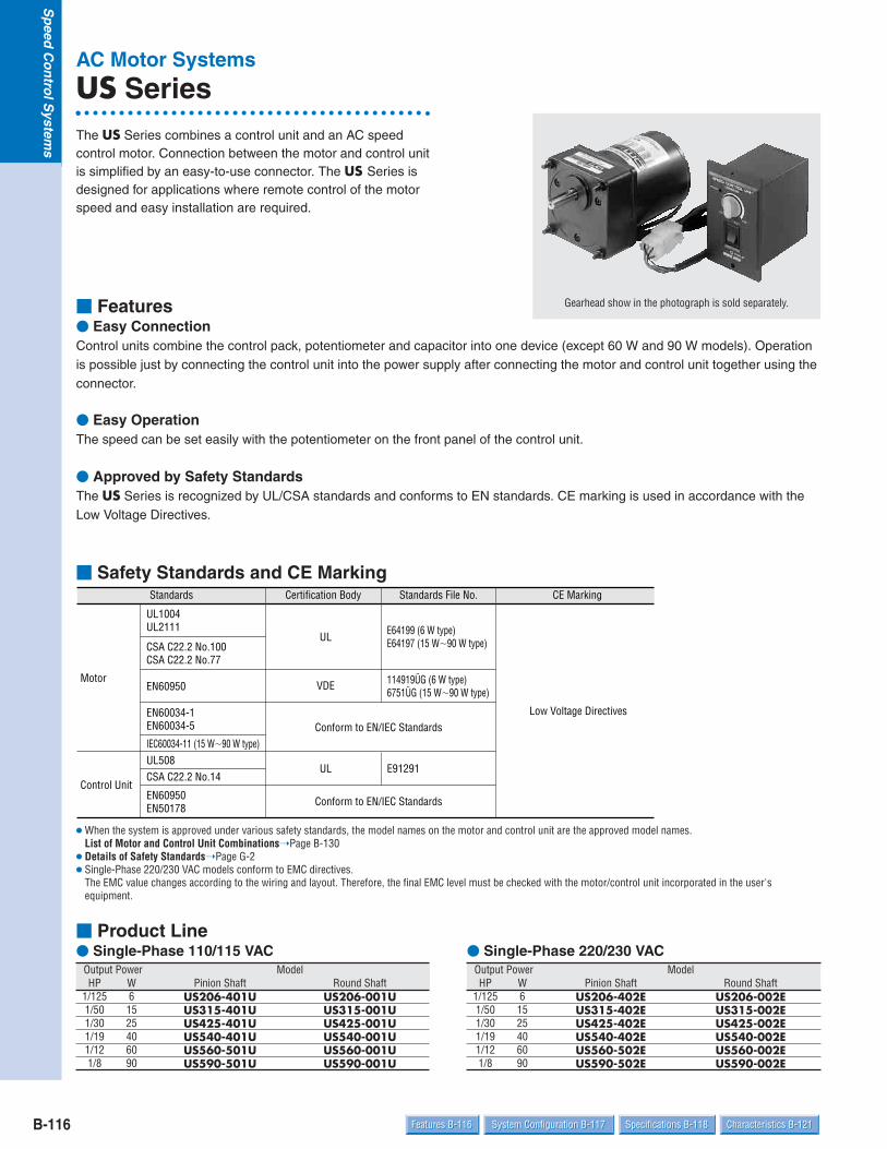
B-116
Sp
eedC
on
trolS
ystems
Specifications B-118 Characteristics B-121System Configuration B-117Features B-116 Specifications B-118 Characteristics B-121System Configuration B-117Features B-116
AC Motor Systems
US SeriesThe US Series combines a control unit and an AC speedcontrol motor. Connection between the motor and control unitis simplified by an easy-to-use connector. The US Series isdesigned for applications where remote control of the motorspeed and easy installation are required.
Features Easy ConnectionControl units combine the control pack, potentiometer and capacitor into one device (except 60 W and 90 W models). Operationis possible just by connecting the control unit into the power supply after connecting the motor and control unit together using theconnector.
Easy OperationThe speed can be set easily with the potentiometer on the front panel of the control unit.
Approved by Safety StandardsThe US Series is recognized by UL/CSA standards and conforms to EN standards. CE marking is used in accordance with theLow Voltage Directives.
Safety Standards and CE Marking
When the system is approved under various safety standards, the model names on the motor and control unit are the approved model names.List of Motor and Control Unit CombinationsPage B-130
Details of Safety StandardsPage G-2 Single-Phase 220/230 VAC models conform to EMC directives.
The EMC value changes according to the wiring and layout. Therefore, the final EMC level must be checked with the motor/control unit incorporated in the user'sequipment.
Standards Certification Body Standards File No. CE Marking
Motor
UL1004UL2111
UL E64199 (6 W type)E64197 (15 W90 W type)
Low Voltage Directives
CSA C22.2 No.100CSA C22.2 No.77
EN60950 VDE 114919ÜG (6 W type)6751ÜG (15 W90 W type)
EN60034-1EN60034-5 Conform to EN/IEC StandardsIEC60034-11 (15 W90 W type)
Control Unit
UL508UL E91291
CSA C22.2 No.14
EN60950EN50178
Conform to EN/IEC Standards
Gearhead show in the photograph is sold separately.
Product Line Single-Phase 110/115 VAC
Output Power ModelHP W Pinion Shaft Round Shaft
1/125 6 US206-401U US206-001U1/50 15 US315-401U US315-001U1/30 25 US425-401U US425-001U1/19 40 US540-401U US540-001U1/12 60 US560-501U US560-001U1/8 90 US590-501U US590-001U
Single-Phase 220/230 VACOutput Power ModelHP W Pinion Shaft Round Shaft
1/125 6 US206-402E US206-002E1/50 15 US315-402E US315-002E1/30 25 US425-402E US425-002E1/19 40 US540-402E US540-002E1/12 60 US560-502E US560-002E1/8 90 US590-502E US590-002E

B-117Dimensions B-123 Connection and Operation B-128Dimensions B-123 Connection and Operation B-128 List of Motor and Control Unit Combinations B-130List of Motor and Control Unit Combinations B-130
Sp
eedC
on
trolS
ystems
Bru
shless D
C M
oto
r System
sDC
Inp
ut
AC
Inp
ut
AC
Mo
tor S
ystems
BX
FBL2
AX
UA
XH
BH
FES
US
Introduction
Before Using aSpeed Control
System
System Configuration
Right-Angle Gearhead(Sold separately)(Page A-189)
US Series
Motor Mounting Brackets(Accessories)(Page A-204)
Flexible Couplings(Accessories)(Page A-208)
Gearhead(Sold separately)
Motor
Motor Speed Indicator (Accessories) Not a standard certified product(Page A-214)
Extension Cables(Accessories)(Page B-130)
Control Unit
Capacitor Cap (Included)Insulates capacitor terminals sectionIncluded with 60 W, 90 W models
(Not Supplied)
Capacitor (Included) Included with 60 W, 90 W
models
ACPower Supply
The system configuration shown is an example. Other configurations are available.
Product Number Code
U105-605USIncluded CapacitorU: 110/115 VACE: 220/230 VAC
Motor Type0: Induction Motor (Continuous rating)
Shaft Type0: Round Shaft4: GN Pinion Shaft (for use with GN-type gearhead)5: GU Pinion Shaft (for use with GU-type gearhead)
Output Power06: 6 W15: 15 W25: 25 W
40: 40 W60: 60 W90: 90 W
Motor Frame Size2: 2.36 in. sq. (60 mm sq.)3: 2.76 in. sq. (70 mm sq.)4: 3.15 in. sq. (80 mm sq.)5: 3.54 in. sq. (90 mm sq.)
Voltage1: Single-Phase 110/115 VAC2: Single-Phase 220/230 VAC
Product Number Code of the GearheadsPage A-16
SeriesUS: US Series
Gearheads (Sold Separately)Motor Model Gearhead Model
US206 Type 2GN3KA2GN180KA2GN10XK (Decimal Gearhead)
US315 Type 3GN3KA3GN180KA3GN10XK (Decimal Gearhead)
US425 Type 4GN3KA4GN180KA4GN10XK (Decimal Gearhead)
US540 Type 5GN3KA5GN180KA5GN10XK (Decimal Gearhead)
US560,US590 Type
5GU3KA5GU180KA5GU10XKB (Decimal Gearhead)
Right-Angle Gearheads (Sold Separately)Type of Shaft Gearhead Model
Hollow Shaft4GN3.6RH4GN180RH5GN3.6RH5GN180RH5GU3.6RH5GU180RH4GN3.6RAA4GN180RAA5GN3RAA5GN180RAA5GU3RAA5GU180RAA
Solid Shaft
US590 Type 5GU50KHA5GU180KHA5GU10XK (Decimal Gearhead)

B-118
Sp
eedC
on
trolS
ystems
Specifications B-118 Characteristics B-121System Configuration B-117Features B-116 Specifications B-118 Characteristics B-121System Configuration B-117Features B-116
General Specifications of the MotorItem Specifications
Overheating Protection Device
Temperature Rise
Dielectric Strength
Insulation Resistance
Insulation ClassAmbient Temperature RangeAmbient Humidity
Degree of Protection
US206 models are impedance protected.All others have built-in thermal protector (Automatic return type)Operating temperature, open: 266°F9°F (130°C5°C) Close: 179.6°F27°F (82°C15°C)
144°F (80°C) or less measured by the resistance change method after rated operation of motor with connected gearhead orequivalent heat radiation plate.
Sufficient to withstand 1.5 kV at 50 Hz and 60 Hz applied between the windings and the frame after rated motor operation undernormal ambient temperature and humidity for 1 minute.
100 MΩ or more when 500 VDC is applied between the windings and the frame after rated motor operation under normal ambienttemperature and humidity.
Class B (266°F [130°C])14°F104°F (10°C40°C) (nonfreezing)85% maximum (non condensing)US206, US315, US425, US540: IP20US560, US590: IP40
SpecificationsModel Maximum
OutputPower
HP
Z US206-401U US206-001U
Z
T
T
T
T
T
T
T
T
T
T
US206-402E
US315-401U
US315-402E
US425-401U
US425-402E
US540-401U
US540-402E
US560-501U
US560-502E
US590-501U
US590-502E
US206-002E
US315-001U
US315-002E
US425-001U
US425-002E
US540-001U
US540-002E
US560-001U
US560-002E
US590-001U
US590-002E
Pinion Shaft Round ShaftW
1/125
1/125
1/50
1/50
1/30
1/30
1/19
1/19
1/12
1/12
1/8
1/8
6
6
15
15
25
25
40
40
60
60
90
90
Voltage
VACSingle-Phase 110
Single-Phase 220
Single-Phase 110
Single-Phase 115
Single-Phase 230Single-Phase 230
Single-Phase 115
Single-Phase 220Single-Phase 230Single-Phase 230Single-Phase 110Single-Phase 115
Single-Phase 220Single-Phase 230Single-Phase 230Single-Phase 110Single-Phase 115
Single-Phase 220Single-Phase 230Single-Phase 230Single-Phase 110Single-Phase 115
Single-Phase 220Single-Phase 230Single-Phase 230Single-Phase 110Single-Phase 115
Single-Phase 220Single-Phase 230Single-Phase 230
Frequency
Hz6060
6050606060
6050606060
6050606060
6050606060
6050606060
605060
Speed Range
r/min901600901600
901600901400901600901600901600
901600901400901600901600901600
901600901400901600901600901600
901600901400901600901600901600
901600901400901600901600901600
901600901400901600
Permissible Torqueoz-in mN·m
7.1 50 4.2 301200r/min 90r/min
7.1 50 4.2 30
7.1 50 4.1 297.1 50 4.1 297.1 50 4.1 2917.7 125 6.3 4517.7 125 6.3 45
12 85 4.9 3517.7 125 4.9 3514.9 105 4.9 3528 200 7.1 5028 200 7.1 50
18.4 130 6.1 4326 190 6.6 47
18.4 130 6.1 4336 260 9.9 7036 260 9.9 70
32 230 8.9 6342 300 8.9 6332 230 8.9 6369 490 28 20069 490 28 200
63 450 22 16069 490 19.8 14063 450 22 160103 730 28 200103 730 28 200
103 730 36 260103 730 32 230103 730 36 260
StartingTorque
oz-in mN·m
4.9 354.9 35
3.8 274.1 294.1 297.8 557.8 55
7.3 527.6 547.8 5514.9 10514.9 105
11.3 8012.3 8712.3 8725.0 18025.0 180
17.7 12519.8 14019.8 14040 28540 285
29 21034 24034 24057 40557 405
51 36056 40056 400
Current
A
PowerConsumption
W0.24 240.25 28
0.13 270.13 280.13 280.47 440.50 44
0.18 390.21 410.22 440.74 700.74 73
0.31 590.35 620.31 601.1 1021.1 105
0.55 980.53 900.55 1002.0 1782.1 186
0.86 1590.89 1540.88 1652.6 2302.6 246
1.2 2211.2 2011.2 227
Z: Impedance Protected.T: Contains a built-in thermal protector. If a motor overheats for any reason, the thermal protector is opened and the motor stops. When the motor
temperature drops, the thermal protector closes and the motor automatically restarts. Be sure to turn off the power before inspecting. The speed ranges shown are under no load conditions. The "U" and "E" at the end of the model number indicate that the unit includes a capacitor. These letters are not listed on the motor nameplate.
Single-Phase 220 50 901400 17.7 125 4.9 35 7.6 54 0.21 40
Single-Phase 220 50 901400 26 190 6.1 43 12.3 87 0.33 60
Single-Phase 220 50 901400 42 300 8.9 63 19.8 140 0.53 90
Single-Phase 220 50 901400 69 490 19.8 140 34 240 0.85 154
Single-Phase 220 50 901400 103 730 32 230 51 360 1.1 200
Single-Phase 220 50 901400 7.1 50 4.1 29 4.1 29 0.13 25
RrC

B-119Dimensions B-123 Connection and Operation B-128Dimensions B-123 Connection and Operation B-128 List of Motor and Control Unit Combinations B-130List of Motor and Control Unit Combinations B-130
Sp
eedC
on
trolS
ystems
Bru
shless D
C M
oto
r System
sDC
Inp
ut
AC
Inp
ut
AC
Mo
tor S
ystems
BX
FBL2
AX
UA
XH
BH
FES
US
Introduction
Before Using aSpeed Control
System
Model (output) Size inch (mm) Thickness inch (mm)US206 Type (6 W) 4.534.53 (115115)US315 Type (15 W) 4.924.92 (125125)US425 Type (25 W) 5.315.31 (135135)US540 Type (40 W) 6.506.50 (165165)US560 Type (60 W) 7.877.87 (200200)US590 Type (90 W) 7.877.87 (200200)
0.20 (5)
Heat radiation plate (material: Aluminum)
General Specifications of the Control UnitItem Specifications
Ambient HumidityAmbient Temperature Range
Dielectric Strength
Insulation Resistance
Degree of Protection85% maximum (noncondensing)32°F104°F (0°C40°C) (nonfreezing)
Sufficient to withstand 2.3 kV (Single phase 220, 230 VAC: 3.0 kV) at 50 Hz and 60 Hz applied between all the pins and the framefor 1 minute.
100 MΩ or more when 500 VDC is applied between all the pins and the frame.
IP10
Speed Range when Gearhead is AttachedGear Ratio
Low Speed
High Speed
3Unit = r/min
60 Hz50 Hz
3.6 5 6 7.5 9 12.5 15 18 25 30 36 50 60 75 90 100 120 150 180
466533
388444
280320
233266
186213
155177
112128
93106
7788
5664
4653
3844
2832
2326
1821
1517
1416
1113
910
78.8
30 25 18 15 12 10 7.2 6 5 3.6 3 2.5 1.8 1.5 1.2 1 0.9 0.75 0.6 0.5
Permissible Torque when a Gearhead is Attached
Model
US206-401U/2GNKA
3Unit = Upper values: lb-in/Lower values: N·m
3.6 5 6 7.5 9 12.5 15 18 25 30 36 50 60 75 90 100 120 150 1801.060.12
1.320.15
1.770.2
2.10.24
2.60.3
3.10.36
4.50.51
5.30.61
6.40.73
80.91
9.71.1
11.51.3
151.7
17.72.0
222.5
263
263
263
263
263
When connecting a decimal gearhead with a gear ratio of 10:1 between the motor and the gearhead, the rotation rate is reduced.The permissible torque with decimal gearheads are as follows.2GNKA/2GN10XK 26 lb-in/3 N·m3GNKA/3GN10XK 44 lb-in/5 N·m4GNKA/4GN10XK 70 lb-in/8 N·m (Gear Ratio 2536 53 lb-in/6 N·m)5GNKA/5GN10XK 88 lb-in/10 N·m5GUKA/5GU10XKB 177 lb-in/20 N·m5GUKHA/5GU10XK 260 lb-in/30 N·m
Single-Phase 110/115 VACGear Ratio
1200 r/min
0.640.073
0.770.088
1.060.12
1.320.15
1.590.18
1.940.22
2.60.3
3.10.36
3.80.44
4.80.55
5.80.66
6.90.79
8.70.99
10.61.2
13.21.5
15.91.8
17.72.0
212.4
263
26390 r/min
2.60.3
3.10.36
4.50.51
5.30.61
6.70.76
80.91
11.51.3
13.21.5
15.91.8
202.3
232.7
293.3
364.1
445
445
445
445
445
445
4451200 r/min
0.970.11
1.150.13
1.590.18
1.940.22
2.30.27
2.90.33
40.46
4.80.55
5.80.66
7.20.82
8.70.99
10.61.2
13.21.5
15.91.8
19.42.2
232.7
263.0
313.6
394.5
44590 r/min
4.30.49
5.10.58
7.10.81
8.50.97
10.61.2
13.21.5
17.72.0
212.4
252.9
323.7
384.4
465.3
586.6
697.9
708
708
708
708
708
7081200 r/min
1.060.12
1.320.15
1.770.2
2.10.24
2.60.3
3.10.36
4.50.51
5.30.61
6.40.73
80.91
9.71.1
11.51.3
151.7
17.72.0
222.5
263.0
293.3
354.0
445.0
525.990 r/min
5.50.63
6.70.76
9.71.1
11.51.3
14.11.6
16.81.9
232.6
283.2
333.8
414.7
505.7
606.8
768.6
8810
8810
8810
8810
8810
8810
88101200 r/min
1.50.17
1.770.2
2.40.28
30.34
3.80.43
4.50.51
6.20.71
7.50.85
8.81.0
11.51.3
13.21.5
15.91.8
202.3
242.8
303.5
374.2
404.6
485.5
616.9
738.390 r/min
10.61.2
12.31.4
17.72.0
212.4
263.0
313.6
394.5
475.4
566.4
718.1
859.7
10211.6
14316.2
17119.4
17720
17720
17720
17720
17720
177201200 r/min
4.30.49
5.10.58
7.10.81
8.50.97
10.61.2
13.21.5
15.91.8
19.42.2
232.6
293.3
354.0
424.8
586.6
697.9
788.9
9310.6
10411.8
12514.2
15617.7
1772090 r/min
15.91.8
18.52.1
263.0
303.5
384.4
465.3
596.7
708.0
849.6
10612.0
12814.5
15317.3
17720
17720
17720
17720
17720
17720
17720
177201200 r/min
4.30.49
5.10.58
7.10.81
8.50.97
10.61.2
13.21.5
15.91.8
19.42.2
232.6
293.3
354.0
424.8
586.6
697.9
788.9
9310.6
10411.8
12514.2
15617.7
1772090 r/min
— — — — — — — — — — — — 21024.1
25028.9
26030
26030
26030
26030
26030
26030 1200 r/min
— — — — — — — — — — — — 586.6
697.9
788.9
9310.6
10411.8
12514.2
15617.7
18721.290 r/min
US315-401U/3GNKA
US425-401U/4GNKA
US540-401U/5GNKA
US560-501U/5GUKA
US590-501U/5GUKA
US590-501U/5GUKHA
Gearheads and decimal gearheads are sold separately. Enter the gear ratio in the box () within the model name. A colored background indicates gear shaft rotation in the same direction as the motor shaft; a white background indicates rotation in the opposite direction.
The speed range is under no load conditions.

B-120
Sp
eedC
on
trolS
ystems
Specifications B-118 Characteristics B-121System Configuration B-117Features B-116 Specifications B-118 Characteristics B-121System Configuration B-117Features B-116
Gearheads and decimal gearheads are sold separately. Enter the gear ratio in the box () within the model name. A colored background indicates gear shaft rotation in the same direction as the motor shaft; a white background indicates rotation in the opposite direction.
Gearmotor — Torque Table when a Right-Angle Gearhead is AttachedPage A-196
Permissible Overhung Load and Permissible Thrust LoadMotor (Round shaft type)Page A-11GearheadPage A-11
Permissible Load Inertia J for GearheadPage A-12
Model
US206-402E/2GNKA
3Unit = Upper values: lb-in/Lower values: N·m
3.6 5 6 7.5 9 12.5 15 18 25 30 36 50 60 75 90 100 120 150 1801.060.12
1.320.15
1.770.2
2.10.24
2.60.3
3.10.36
4.50.51
5.30.61
6.40.73
80.91
9.71.1
11.51.3
151.7
17.72.0
222.5
263
263
263
263
263
Single-Phase 220/230 VACGear Ratio
1200 r/min
0.610.07
0.750.085
1.060.12
1.230.14
1.590.18
1.850.21
2.50.29
30.35
3.70.42
4.60.53
5.60.64
6.70.76
8.40.96
9.71.1
12.31.4
151.7
16.81.9
202.3
252.9
26390 r/min
1.850.21
2.20.25
30.34
3.60.41
4.60.52
5.40.62
7.60.86
8.81.0
10.61.2
14.11.6
16.81.9
19.42.2
242.8
303.4
374.2
445
445
445
445
445
1200r/min
0.750.085
0.880.1
1.230.14
1.50.17
1.850.21
2.30.26
30.35
3.80.43
4.50.51
5.60.64
6.80.77
8.10.92
10.61.2
12.31.4
151.7
18.52.1
202.3
242.8
303.5
374.290 r/min
2.80.32
3.30.38
4.60.53
5.50.63
6.90.79
8.40.95
11.51.3
14.11.6
16.81.9
212.4
242.8
303.4
384.3
455.1
566.4
687.7
708
708
708
7081200
r/min
0.880.1
1.150.13
1.50.17
18.50.21
2.30.26
2.70.31
3.80.44
4.60.52
5.50.63
6.90.78
8.30.94
9.71.1
12.31.4
151.7
18.52.1
232.6
242.8
303.4
384.3
455.190
r/min
4.90.56
5.90.67
8.20.93
9.71.1
12.31.4
151.7
202.3
242.8
303.4
374.2
445.0
536.0
677.6
809.1
8810
8810
8810
8810
8810
88101200
r/min
1.320.15
1.590.18
2.30.26
2.70.31
3.30.38
40.46
5.60.64
6.80.77
8.10.92
9.71.1
12.31.4
151.7
18.52.1
222.5
273.1
323.7
374.2
445.0
546.2
667.590 r/min
9.71.1
11.51.3
15.91.8
19.42.2
232.7
293.3
364.1
434.9
525.9
657.4
788.9
9410.7
13114.9
15717.8
17619.9
17720
17720
17720
17720
177201200
r/min
3.40.39
4.10.47
5.70.65
6.90.78
8.50.97
10.61.2
13.21.5
15.91.8
18.52.1
232.6
283.2
333.8
465.3
556.3
627.1
758.5
839.4
10011.3
12514.2
1501790
r/min
15.91.8
18.52.1
263.0
303.5
384.4
465.3
596.7
708.0
849.6
10612.0
12814.5
15317.3
17720
17720
17720
17720
17720
17720
17720
177201200 r/min
5.50.63
6.70.76
9.71.1
11.51.3
14.11.6
16.81.9
212.4
242.8
303.4
384.3
455.1
546.2
768.6
9110.3
10111.5
12213.8
13515.3
16218.4
17720
1772090
r/min
— — — — — — — — — — — — 21024.1
25028.9
26030
26030
26030
26030
26030
26030 1200 r/min
— — — — — — — — — — — — 768.6
9110.3
10111.5
12213.8
13515.3
16218.4
20023
24027.690
r/min
US315-402E/3GNKA
US425-402E/4GNKA
US540-402E/5GNKA
US560-502E/5GUKA
US590-502E/5GUKA
US590-502E/5GUKHA
2.60.3
3.10.36
4.50.51
5.30.61
6.70.76
80.91
11.51.3
13.21.5
15.91.8
202.3
232.7
293.3
364.1
445
445
445
445
445
445
445
220 VAC60 Hz
230 VAC50 Hz
230 VAC60 Hz
2.30.26
2.70.31
3.80.43
4.50.51
5.60.64
6.80.77
9.71.1
11.51.3
13.21.5
16.81.9
202.3
242.8
303.5
374.2
445
445
445
445
445
445
220/230 VAC60 Hz
40.46
4.80.55
6.80.77
8.10.92
10.61.2
12.31.4
16.81.9
202.3
242.8
303.5
374.2
445.0
556.3
667.5
708
708
708
708
708
708
230 VAC50 Hz
220/230 VAC60 Hz
230 VAC50 Hz
0.970.11
1.230.14
1.680.19
20.23
2.50.29
30.34
4.20.48
50.57
6.10.69
7.60.86
8.81.0
10.61.2
14.11.6
16.81.9
202.3
242.8
273.1
323.7
414.7
495.6
220/230 VAC60 Hz
230 VAC50 Hz
6.40.73
7.60.87
10.61.2
13.21.5
15.91.8
19.42.2
263.0
313.6
384.4
485.5
586.6
697.9
879.9
8810
8810
8810
8810
8810
8810
8810
220/230 VAC60 Hz
230 VAC50 Hz
220/230 VAC60 Hz
230 VAC50 Hz
10.61.2
12.31.4
17.72.0
212.4
263.0
313.6
394.5
475.4
566.4
718.1
859.7
10211.6
14316.2
17119.4
17720
17720
17720
17720
17720
17720
30.34
3.60.41
50.57
60.68
7.50.85
8.81.0
11.51.3
13.21.5
15.91.8
202.3
242.8
293.3
404.6
485.5
546.2
657.4
738.3
879.9
10912.4
13114.9
4.90.56
5.90.67
8.20.93
9.71.1
12.31.4
151.7
18.52.1
222.5
263.0
333.8
404.6
485.5
677.6
809.1
9010.2
10712.2
12013.6
14416.3
17720
17720
220/230 VAC60 Hz
230 VAC50 Hz
— — — — — — — — — — — — 677.6
809.1
9010.2
10712.2
12013.6
14416.3
18020.4
21024.4
220/230 VAC60 Hz
230 VAC50 Hz

B-121Dimensions B-123 Connection and Operation B-128Dimensions B-123 Connection and Operation B-128 List of Motor and Control Unit Combinations B-130List of Motor and Control Unit Combinations B-130
Sp
eedC
on
trolS
ystems
Bru
shless D
C M
oto
r System
sDC
Inp
ut
AC
Inp
ut
AC
Mo
tor S
ystems
BX
FBL2
AX
UA
XH
BH
FES
US
Introduction
Before Using aSpeed Control
System Speed — Torque CharacteristicsUS206-401U US206-402EUS206-001U US206-002E
US315-401U US315-402EUS315-001U US315-002E
US425-401U US425-402EUS425-001U US425-001E
90 18001000500
Speed [r/min]
Permissible Torque when Gearhead is Attached
60 Hz Safe-Operation Line
15001400 1600
50 Hz 230 VAC60 Hz 230 VAC50 Hz 220 VAC60 Hz 220 VAC
50 Hz Safe-Operation Line[oz-
in]
[mN·
m]
0
50
100
150
200
250
300
0
5
10
15
20
25
30
35
40
Torq
ue
110 VAC115 VAC
900
20
10
25
30
[mN·
m]
1800150014001600
1000500
Speed [r/min]
150
200
250
300
[oz-
in]
100
505
15
35
40
0
Torq
ue
Safe-Operation Line
Permissible Torque when Gearhead is Attached
230 VAC/60 Hz Safe-Operation Line
50 Hz Safe-Operation Line
90
Permissible Torque when Gearhead is Attached
180015001400 1600
1000500
Speed [r/min]
220 VAC/60 Hz Safe-Operation Line
50 Hz 230 VAC60 Hz 230 VAC50 Hz 220 VAC60 Hz 220 VAC
[oz-
in]
[mN·
m]
0
40
80
120
160
0
5
10
15
20
25
Torq
ue
10
5
15
20
25
[oz-
in]
180015001400 1600
100050090
Speed [r/min]
80
40
120
160
200
[mN·
m]
0 0
Torq
ue
Safe-Operation LinePermissible Torque when Gearhead is Attached
110 VAC115 VAC
230 VAC/60 Hz Safe-Operation Line
220 VAC/50 Hz Safe-Operation Line
230 VAC/50 Hz Safe-Operation Line
1800100050090
Speed [r/min]
220 VAC/60 Hz Safe-Operation LinePermissible Torque whenGearhead is Attached
15001400 1600
50 Hz 230 VAC60 Hz 230 VAC50 Hz 220 VAC60 Hz 220 VAC
[oz-
in]
[mN·
m]
0 0
2
4
6
8
10
12
20
40
60
80
Torq
ue
0
2
4
6
8
[oz-
in]
20
40
60
80
[mN·
m]
180015001400 1600
100050090
Speed [r/min]
110 VAC115 VAC
10
0
Torq
ue
Safe-Operation Line
Permissible Torque when Gearhead is Attached

B-122
Sp
eedC
on
trolS
ystems
Specifications B-118 Characteristics B-121System Configuration B-117Features B-116 Specifications B-118 Characteristics B-121System Configuration B-117Features B-116
US540-401U US540-402EUS540-001U US540-002E
US560-501U US560-502EUS560-001U US560-002E
US590-501U US590-502EUS590-001U US590-002E
1800100050090
Speed [r/min]
50 Hz Safe-Operation Line
220 VAC/60 Hz Safe-Operation Line
230 VAC/60 Hz Safe-Operation Line
Permissible Torque when Gearhead is Attached
15001400 1600
50 Hz 230 VAC60 Hz 230 VAC50 Hz 220 VAC60 Hz 220 VAC
[oz-
in]
[mN·
m]
0
0.2
0.4
0.6
0.8
1.0
1.2
0
20
40
60
80
100
120
140
160
Torq
ue
110 VAC115 VAC
120
80
60
40
20
[oz-
in]
1.0
0.8
0.6
0.4
0.2
[N·m
]
018001500
1400 1600100050090
Speed [r/min]
100
140
0
Torq
ue
Safe-Operation LinePermissible Torque when Gearhead is Attached
180015001400 1600
100050090
Speed [r/min]
50 Hz Safe-Operation Line
Permissible Torque when Gearhead is Attached
60 Hz Safe-Operation Line
50 Hz 230 VAC60 Hz 230 VAC50 Hz 220 VAC60 Hz 220 VAC
[oz-
in]
[mN·
m]
0
0.2
0.4
0.6
0.8
1.0
0
20
40
60
80
100
120
140To
rque
100
80
60
40
[oz-
in]
20
1.0
0.8
0.6
0.4
0.2
[N·m
]
018001500
1400 16001000500
Speed [r/min]
90
110 VAC115 VAC
140
120
0
Torq
ue
Permissible Torque when Gearhead is Attached
Safe-Operation Line
180015001400 1600
1000500
Speed [r/min]
90
Permissible Torque when Gearhead is Attached
60 Hz Safe-Operation Line
50 Hz Safe-Operation Line
50 Hz 230 VAC60 Hz 230 VAC50 Hz 220 VAC60 Hz 220 VAC
[oz-
in]
[mN·
m]
0
0.1
0.2
0.3
0.4
0.5
0
10
20
30
40
50
60
70
Torq
ue
110 VAC115 VAC
50
40
30
[oz-
in]
20
0
0.4
0.3
0.2
0.1
[N·m
]
180015001400 1600
1000500
Speed [r/min]
90
10
60
0
Torq
ue
Safe-Operation LinePermissible Torque when Gearhead is Attached

B-123Dimensions B-123 Connection and Operation B-128Dimensions B-123 Connection and Operation B-128 List of Motor and Control Unit Combinations B-130List of Motor and Control Unit Combinations B-130
Sp
eedC
on
trolS
ystems
Bru
shless D
C M
oto
r System
sDC
Inp
ut
AC
Inp
ut
AC
Mo
tor S
ystems
BX
FBL2
AX
UA
XH
BH
FES
US
Introduction
Before Using aSpeed Control
System Dimensions Scale 1/4, Unit = inch (mm)
Mounting screws are included with gearheads. Dimensions for screws Page A-223Enter the gear ratio in the box () within the model name.
Motor/Gearhead
d A078AU (2GN3KA18KA)A078BU (2GN25KA180KA)
L
2.
36 (
60)
1.
85 (
47)
0.39 (10) 1.26 (32)0.12 (3)
0.50(12.7)
2.95 (75)0.28(7)
0.39
(10)
0.
94(
24)0.
293
(7.4
37)
0(7.9370.015)
2GN3KA~18KA: L = 1.18 (30)2GN25KA~180KA: L = 1.57 (40)
Housing14803400 (AMP)
Leads, 10 inch (250 mm) LengthW/connector
2230'
2.760.02
(700.5)
2.36 (60)
0.177 (4.5)4 Holes
0.0006 00.3125 5/16"
Gearhead: 2GNKAWeight: 0.88 lb. (0.4 kg)
US206-401U, US206-402E (Pinion Shaft Type)Motor: USM206-401W, USM206-402WWeight: 1.76 lb. (0.8 kg)
Round Shaft TypeUS206-001U, US206-002EMotor: USM206-001W, USM206-002WWeight: 1.76 lb. (0.8 kg)d A354
2.760.02
(700.5)
2.36 (60)
0.94(24)
22 30
0.08(2)
(60.012)00.0005
00.2362
(54
0.03
0)0
0.00
12 0
2.
1260
0.177 (4.5)4 Holes
Decimal GearheadCan be connected to US206GN pinion shaft type2GN10XKWeight: 0.44 lb. (0.2 kg)d A003
1.52 (38.5)1.02(26)
0.49(12.5)
0.08(2)
0.177 (4.5) 4 Holes
2.76 0.02
(70 0.5)
2.36 (60)
( 54
0.
030)
0.
0012
0
0
2.
1260
Motor/Gearhead
d A079AU (3GN3KA18KA)A079BU (3GN25KA180KA)
3GN3KA~18KA: L = 1.26 (32)3GN25KA~180KA: L = 1.65 (42)
Housing 14803400 (AMP)
Leads,10 inch (250 mm) Length W/connector
L
2.
72 (
69)
1.
85 (
47)
3.15 (80)
0.28(7)
0.39 (10) 1.26 (32)
0.12 (3)
1.
18(
30)
3/8"
0.59
(15)0.50
(12.7) 0.34
7 (8
.825
) 0(9.5250.015)0.0006
00.3750
2230'
2.76 (70)
3.230.02
(820.5)
0.217 (5.5) 4 Holes
Gearhead: 3GNKAWeight: 1.21 lb. (0.55 kg)
US315-401U, US315-402E (Pinion Shaft Type)Motor: USM315-401W, USM315-402WWeight: 2.6 lb. (1.2 kg)

B-124
Sp
eedC
on
trolS
ystems
Specifications B-118 Characteristics B-121System Configuration B-117Features B-116 Specifications B-118 Characteristics B-121System Configuration B-117Features B-116
Round Shaft TypeUS315-001U, US315-002EMotor: USM315-001W, USM315-002WWeight: 2.6 lb. (1.2 kg)d A355
3.230.02
(820.5)
2.76 (70)1.26 (32)
0.08(2)
0.217 (5.5) 4 Holes
22 30
(60.012)00.0005
00.2362
(64
0.
030)
00.
0012
0
2.51
97
Decimal GearheadCan be connected to US315GN pinion shaft type3GN10XKWeight: 0.66 lb. (0.3 kg)d A009
1.69 (43)1.18(30) 0.51 (13)
0.08(2)
0.217 (5.5) 4 Holes
3.23 0.02
(82 0.5)
2.76 (70)
( 64
0.03
0)0
0.00
12 0
2.
5197
Motor/Gearhead
d A080AU (4GN3KA18KA)A080BU (4GN25KA180KA)
L
3.
11 (
79)
1.
85 (
47)
0.39 (10) 3.35 (85)
0.28(7)
1.26 (32)
(34
)
1.340.
59 ( 1
5)
0.12 (3)3/8"
0.50(12.7) 0.
347
( 8.8
25)
0.217 (5.5) 4 Holes
3.15 (80)
3.700.02
(940.5)
(9.5250.015)00.0006
00.3750
4GN3KA~18KA: L = 1.26 (32)4GN25KA~180KA: L = 1.67 (42.5)
Housing 14803400 (AMP)
Leads,10 inch (250 mm) Length W/connector
22 30
Gearhead: 4GNKAWeight: 1.43 lb. (0.65 kg)
US425-401U, US425-402E (Pinion Shaft Type)Motor: USM425-401W, USM425-402WWeight: 3.5 lb. (1.6 kg)
Round Shaft TypeUS425-001U, US425-002EMotor: USM425-001W, USM425-002WWeight: 3.5 lb. (1.6 kg)d A356
3.700.02
(940.5)
22 30
3.15 (80)1.26 (32)
0.08(2)
0.98(25) 0.
28 (7
)
(80.015)00.0006
00.3150
(73
0.
030)
00.
0012
0
2.87
40
0.217 (5.5) 4 Holes
Decimal GearheadCan be connected to US425GN pinion shaft type4GN10XKWeight: 0.88 lb. (0.4 kg)d A013
1.79 (45.5)
1.26 (32) 0.53 (13.5)
0.08(2)
0.217 (5.5) 4 Holes
( 73
0.
030)
0.
0012
0 0
2.
8740
3.15 (80)
3.70 0.02
(94 0.5)
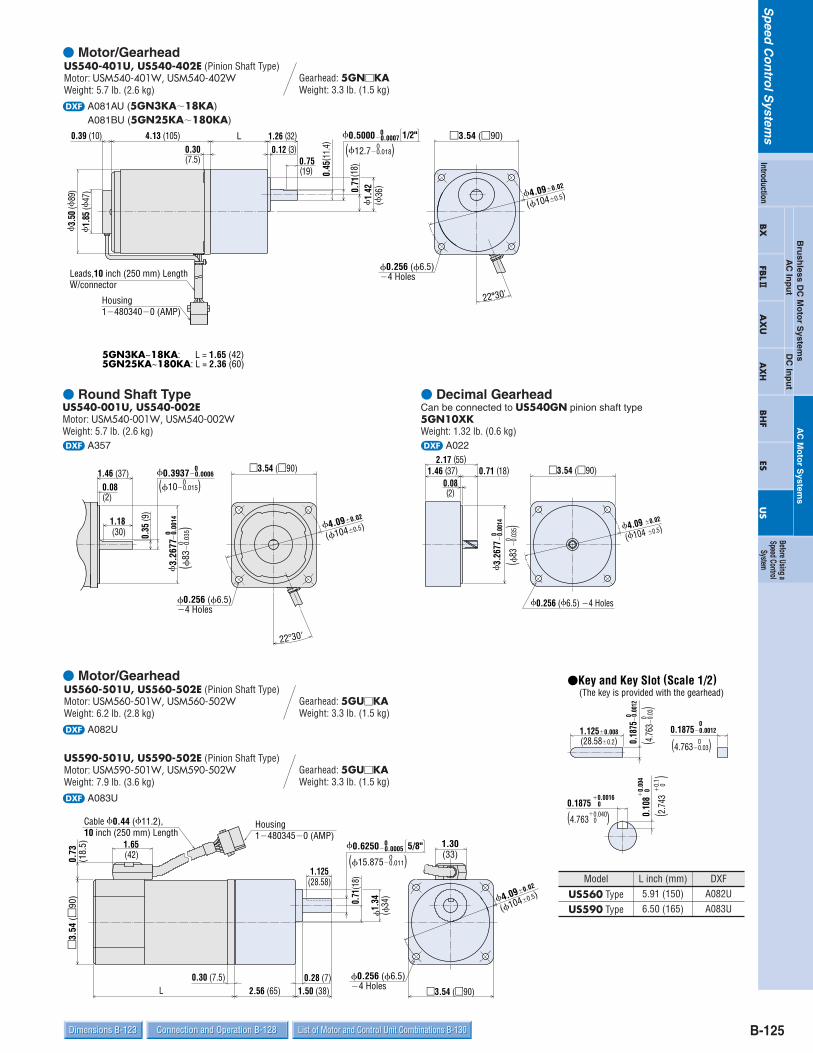
B-125Dimensions B-123 Connection and Operation B-128Dimensions B-123 Connection and Operation B-128 List of Motor and Control Unit Combinations B-130List of Motor and Control Unit Combinations B-130
Sp
eedC
on
trolS
ystems
Bru
shless D
C M
oto
r System
sDC
Inp
ut
AC
Inp
ut
AC
Mo
tor S
ystems
BX
FBL2
AX
UA
XH
BH
FES
US
Introduction
Before Using aSpeed Control
System Motor/Gearhead
d A081AU (5GN3KA18KA)A081BU (5GN25KA180KA)
Housing 14803400 (AMP)
Leads,10 inch (250 mm) Length W/connector
L
3.
50 (
89)
1.
85 (
47)
0.39 (10) 4.13 (105)0.30(7.5)
0.12 (3)1.26 (32)
0.71
(18)
1.
42(
36)
1/2"
0.75(19)
(12.70.018)0
0.45
( 11.
4)
0.0007 00.5000
5GN3KA~18KA: L = 1.65 (42)5GN25KA~180KA: L = 2.36 (60)
2230'
3.54 (90)
4.090.02
(1040.5)
0.256 (6.5) 4 Holes
Gearhead: 5GNKAWeight: 3.3 lb. (1.5 kg)
US540-401U, US540-402E (Pinion Shaft Type)Motor: USM540-401W, USM540-402WWeight: 5.7 lb. (2.6 kg)
Round Shaft TypeUS540-001U, US540-002EMotor: USM540-001W, USM540-002WWeight: 5.7 lb. (2.6 kg)d A357
1.46 (37)
0.35
(9)
1.18 (30)
0.08(2)
(100.015)00.0006
00.3937
(83
0.
035)
0
0.00
14 0
3.
2677
4.090.02
(1040.5)
2230
3.54 (90)
0.256 (6.5) 4 Holes
Decimal GearheadCan be connected to US540GN pinion shaft type5GN10XKWeight: 1.32 lb. (0.6 kg)d A022
1.46 (37) 0.71 (18)2.17 (55)
0.08(2)
3.54 (90)
0.256 (6.5) 4 Holes
(83
0.
035)
00.
0014
0
3.26
77
4.09 0.02
(104 0.5)
Motor/Gearhead
d A082U
d A083U
0.73
(18.
5) 1.65
1.
34
(42)
3.
54 (
90)
L0.30 (7.5)
2.56 (65)0.28 (7)
1.50 (38)
1.125(28.58)
0.71
(18)
(34
)
5/8"
Housing 14803450 (AMP)
Cable 0.44 (11.2),10 inch (250 mm) Length
(15.8750.011)00.0005
00.6250 1.30(33)
4.090.02
(1040.5)
3.54 (90)
0.256 (6.5) 4 Holes
Gearhead: 5GUKAWeight: 3.3 lb. (1.5 kg)
US590-501U, US590-502E (Pinion Shaft Type)Motor: USM590-501W, USM590-502WWeight: 7.9 lb. (3.6 kg)
Gearhead: 5GUKAWeight: 3.3 lb. (1.5 kg)
US560-501U, US560-502E (Pinion Shaft Type)Motor: USM560-501W, USM560-502WWeight: 6.2 lb. (2.8 kg)
1.1250.008(28.580.2) 0(4.7630.03)
00.18750.0012
0( 4.7
63
0.03
)0
0.18
75
0.00
12
0.040(4.763 0 )
0.00160.1875 0
0.
1
0.
004
0.10
8 0
Key and Key Slot (Scale 1/2) (The key is provided with the gearhead)
(2.74
3
0
)
Model L inch (mm)
US560 Type 5.91 (150)
US590 Type 6.50 (165)
DXFA082UA083U

B-126
Sp
eedC
on
trolS
ystems
Specifications B-118 Characteristics B-121System Configuration B-117Features B-116 Specifications B-118 Characteristics B-121System Configuration B-117Features B-116
Round Shaft TypeUS560-001U, US560-002EMotor: USM560-001W, USM560-002WWeight: 6.2 lb. (2.8 kg)d A358
US590-001U, US590-002EMotor: USM590-001W, USM590-002WWeight: 7.9 lb. (3.6 kg)d A359
4.090.02
(1040.5)
1.30(33)
1.46 (37)0.08(2)
3.54 (90)
0.43
(11)
1.18(30)
(120.018)00.0007
00.4724(
83
0.03
5)0
0.00
14 0
3.
2677
0.256 (6.5) 4 Holes
Decimal GearheadCan be connected to US560GU and US590GU pinion shaft type5GU10XKB (For 5GUKA), 5GU10XK (For 5GUKHA)Weight: 1.32 lb. (0.6 kg)d A029
2.40 (61)1.57 (40)
0.08(2)
3.54 (90)
5GU10XKB: 0.425 (10.8) 4 Holes5GU10XK: 0.256 (6.5) 4 Holes
0.83 (21)
( 83
0.
035)
00.
0014
0
3.26
77
4.09 0.02
(104 0.5)
High-Power Gearheads5GUKHAWeight: 4.2 lb. (1.9 kg)d A038U
M6 P14Places
0.39 (10)3.35 (85)
1.93 (49)
1.65 (42)
1.125(28.58)
0.47 (12)
0.335 (8.5)4 Holes
0.28 (7)
3.
54 (
90)
1.93
(49)
0.71
(18)
1.
57
(40
)
(104 ±0.5)
(19.050.021)00.0008
00.7500
4.09 0.02
0.0020 00.188 0.0020
00.188
0.
0020
00.
188
1.125(28.58)
0.10
6(2
.69)
(4.763 0.051)0 (4.763 0 ) 0.051
(4.7
63
0.05
1)0
Key and Key Slot (Scale 1/2) (The key is provided with the gearhead)

B-127Dimensions B-123 Connection and Operation B-128Dimensions B-123 Connection and Operation B-128 List of Motor and Control Unit Combinations B-130List of Motor and Control Unit Combinations B-130
Sp
eedC
on
trolS
ystems
Bru
shless D
C M
oto
r System
sDC
Inp
ut
AC
Inp
ut
AC
Mo
tor S
ystems
BX
FBL2
AX
UA
XH
BH
FES
US
Introduction
Before Using aSpeed Control
System Control UnitFor use with US206, US315, US425 and US540 typesUSP206-1U/USP206-2EUSP315-1U/USP315-2EUSP425-1U/USP425-2EUSP540-1U/USP540-2EWeight: 0.99 lb. (0.45 kg)d A817
Cable 0.29 (7.3 ),20 inch (500 mm) LengthW/ConnectorHousing: 1-480270-0 (AMP)
Power Cord 6.6 feet (2 m)
Protective Earth Lead 6.6 feet (2 m)UL Style 1007, AWG 22
2.050.04(521)
3.15
0.
04 (8
01)
3.54 max. (90) 0.45 (11.5)
0.08 (2)2.99 (76)
0.06 (1.5)
3.94
(100
)
2.36 (60)0.66 (16.8)
0.12 (3)
1.02
(26)
0.59 (15)
0.59 (15)
3.54
0.
02(9
0
0.5)
0.18 (4.5)2 Holes
For use with US560 and US590 typesUSP560-1U/USP560-2EUSP590-1U/USP590-2EWeight: 1.1 lb. (0.5 kg)d A818
Cable 0.44 (11.2 ),20 inch (500 mm) LengthW/ConnectorHousing: 1-480270-0 (AMP)
Capacitor Leads 14 (350)
Power Cord 6.6 feet (2 m)
Protective Earth Lead 6.6 feet (2 m)UL Style 1007, AWG 22
2.050.04(521)
3.15
0.
04(8
01)
3.54 max. (90) 0.45 (11.5)
0.08 (2)2.99 (76)
0.06 (1.5)
3.94
(100
)
2.36 (60)0.66 (16.8)
0.12 (3)
1.02
(26)
0.59 (15)
0.59 (15) 3.54
0.
02(9
0 0.5
)
0.18 (4.5)2 Holes
Panel Cut-Out for Control UnitInstallation Method by Cutting a Hole
3.54
0.
008
3.19
0.
04
0
2.09 0.04 0
0.18 ( 4.5 ) Holes2 Places
(53 )1 0
(81
)
1
0
(90
)
0.2

B-128
Sp
eedC
on
trolS
ystems
Specifications B-118 Characteristics B-121System Configuration B-117Features B-116 Specifications B-118 Characteristics B-121System Configuration B-117Features B-116
Capacitor (included with the motors)
0.24 (6)
A
CB
0.28
(7)
(20)
0.39
(10)
0.169
AMP#1870.
16 (4
)B+
0.59
(15)
R0.39 (10)
0.79(4.3)
Capacitor Dimensions Unit = inch (mm)
If you need to order a capacitor without a motor, add "-C" to the capacitor model nameshown. A capacitor cap is included with a capacitor.
US560-01U CH180CFAUL 2.28 (58) 0.93 (23.5) 1.46 (37) 2.5 (70)
Package Model CapacitorModel A B C Weight
oz (g)
US560-02E CH40BFAUL 2.28 (58) 0.93 (23.5) 1.46 (37) 2.5 (70)US590-01U CH200CFAUL 2.28 (58) 1.14 (29) 1.61 (41) 3.4 (95)US590-02E CH60BFAUL 2.28 (58) 1.14 (29) 1.61 (41) 3.0 (85)
Connection DiagramsUS206, US315, US425, US540 types
SPEEDOUT
L N (CW)
N (CCW) FG
1
10
11
2
9
Uni-directional Rotation:
L N (CW)
N (CCW)
CW
CCWSW2
SW1
Motor Speed Indicator (optional)SDM496Pin No.
Control Unit Rear Panel
FrameGround
FrameGround (Ground Lead: Green)
White
Black
Power Supply
Bi-directional Rotation:
Switch Specifications: 250 VAC, Inductive Load, 5 A min.
Single-Phase 110/115 VAC 60 HzSingle-Phase 220 VAC 50/60 HzSingle-Phase 230 VAC 50/60 Hz
Single-Phase 110/115 VAC 60 HzSingle-Phase 220 VAC 50/60 HzSingle-Phase 230 VAC 50/60 Hz
US560, US590 types
Motor Speed Indicator (optional)SDM496Pin No.
1
10
11
2Control Unit Rear Panel
FrameGround
FrameGround (Ground Lead: Green)
Capacitor
SPEEDOUT
L N (CW)
N (COM) N (CCW)
FG
L
N (CW)
N (COM)
N (CCW) CW
CCWSW2
SW1
9White
Black
Power Supply
Uni-directional Rotation:
Bi-directional Rotation:
Switch Specifications: 250 VAC, Inductive Load, 5 A min.
Single-Phase 110/115 VAC 60 HzSingle-Phase 220 VAC 50/60 HzSingle-Phase 230 VAC 50/60 Hz
Single-Phase 110/115 VAC 60 HzSingle-Phase 220 VAC 60 HzSingle-Phase 230 VAC 50/60 Hz
If an extension between the motor and control unit is required, an extension cable can be used (sold separately).Using the longest cord, the distance can be extended up to 15.7 feet (4.75 m).Page B-130
Connection and Operation
Speed Potentiometer
RUN/STAND-BY Switch
POWER LED
In the diagrams above, the motor shaft rotates in the clockwisedirection. When changed to the dotted line [N (CCW)] position,the motor shaft rotates in the counterclockwise direction.

B-129Dimensions B-123 Connection and Operation B-128Dimensions B-123 Connection and Operation B-128 List of Motor and Control Unit Combinations B-130List of Motor and Control Unit Combinations B-130
Sp
eedC
on
trolS
ystems
Bru
shless D
C M
oto
r System
sDC
Inp
ut
AC
Inp
ut
AC
Mo
tor S
ystems
BX
FBL2
AX
UA
XH
BH
FES
US
Introduction
Before Using aSpeed Control
System Inner Connection Diagram for 4-Terminal CapacitorTerminals of the capacitor are connected as shown in thefigure. For lead wire connection, use one lead wire perterminal.
Operation MethodThere is a difference in operation method between theUS206, US315, US425, US540 types and the US560,US590 types.
US206, US315, US425 and US540 types Connect the motor lead wire connectors to the control unit.Then connect the power cord to the power supply. When theRUN/STAND-BY switch of the control unit is switched toRUN, the motor rotates in the clockwise (CW) direction asseen from the motor shaft. (Control units are set for clockwise rotation at shipment. Thedirection of rotation for the gearhead output shaft may be thereverse of the direction of the motor shaft depending on thegear ratio.)
US560 and US590 types Connect the control unit and the motor, and attach thecapacitor wire leading from the control unit to the capacitor.Next, plug in the power supply cord into an AC power supply.When the RUN/STAND-BY switch located on the control unitis switched to RUN, the motor will rotate in the direction setby the connection of the capacitor. (Control units are set for clockwise rotation at shipment. Thedirection of rotation for the gearhead output shaft may be thereverse of the direction of the motor shaft depending on thegear ratio.)
Changing Speed When the potentiometer located on the front of the controlunit is turned in a clockwise direction, motor speedincreases; when turned in the counter clockwise direction,motor speed decreases. Motor speed can be set andadjusted over a range of 90 r/min-1600 r/min.
Stopping When the RUN/STAND-BY switch on the control unit is set toSTAND-BY, the motor stops. This switch is not a powerON/OFF switch. If the motor is to be stopped for a long time,a separate power ON/OFF switch should be installed.
Changing the Direction of Rotation US206, US315, US425 and US540 types (Capacitor is included in the control unit.)
Uni-directional RotationWhen the direction of motor rotation needs to be reversed forreasons relating to transmission mechanisms such asgearheads, change the terminal used for attaching the powercord, located at the back of control unit, from terminal N(CW) to terminal N (CCW). The power cord connections arelocated at terminals L and N (CW) when shipped. See thediagram on the previous page.(This should always be done with the power OFF.)
Bi-directional RotationInstall an additional power switch (SW1) and CW/CCWswitch (SW2) as shown on previous page, and use theseswitches to change the direction of rotation. (Motor cannot bereversed instantaneously. Turn SW1 off and wait until themotor has come to a complete stop before switching SW2.)See the diagram on the previous page.
US560 and US590 types (Connection of the included capacitor is necessary.)
Uni-directional RotationWhen the direction of motor rotation needs to be reversed,change the terminal used for attaching the power cord,located at the back of control unit, from terminals N (CW)-N(COM) to terminals N (COM)-N (CCW). The power cordconnections are located at terminals N (CW)-N (COM) whenshipped. See the diagram on the previous page.(This should always be done with the power OFF.)
Bi-directional RotationInstall an additional power switch (SW1) and CW/CCWswitch (SW2) as shown on the previous page, and use theseswitches to change the direction of rotation. (Motor cannot bereversed instantaneously. Turn SW1 off and wait until themotor has come to a complete stop before switching SW2.) See the diagram on the previous page.

B-130
Sp
eedC
on
trolS
ystems
Output PowerHP W
1/125
1/50
1/30
1/19
1/12
1/8
6
15
25
40
60
90
Output PowerHP W
US206-401UUS206-001UUS315-401UUS315-001UUS425-401UUS425-001UUS540-401UUS540-001UUS560-501UUS560-001UUS590-501UUS590-001U
1/125
1/50
1/30
1/19
1/12
1/8
6
15
25
40
60
90
Package Model
USM206-401WUSM206-001WUSM315-401WUSM315-001WUSM425-401WUSM425-001WUSM540-401WUSM540-001WUSM560-501WUSM560-001WUSM590-501WUSM590-001W
Motor Model
USP206-1U
USP315-1U
USP425-1U
USP540-1U
USP560-1U
USP590-1U
Control Unit Model
US206-402EUS206-002EUS315-402EUS315-002EUS425-402EUS425-002EUS540-402EUS540-002EUS560-502EUS560-002EUS590-502EUS590-002E
Package Model
USM206-402WUSM206-002WUSM315-402WUSM315-002WUSM425-402WUSM425-002WUSM540-402WUSM540-002WUSM560-502WUSM560-002WUSM590-502WUSM590-002W
Motor Model
USP206-2E
USP315-2E
USP425-2E
USP540-2E
USP560-2E
USP590-2E
Control Unit Model
List of Motor and Control Unit CombinationsModel numbers for motor and control unit combinations are shown below.
Extension Cable (Sold separately)When installing the motor and control unit in different locations, an extension cable can be used (sold separately). This enablesremote operation at a distance of up to 15.7 feet. (4.75 m).
Applicable Products:US206, US315, US425, US540
Single-Phase 110/115 VAC Single-Phase 220/230 VAC
Length: L ft. (m)3.3 (1)6.6 (2)9.8 (3)
13.1 (4)
L
1-480270-0 (AMP)Housing
1-480340-0 (AMP)Housing
Motor Side Control Unit Side
L
Motor Side Control Unit Side
1-480283-0(AMP)Housing
1-480345-0(AMP)Housing
ModelCC01SS052CC02SS052CC03SS052CC04SS052
Applicable Products:US560, US590
Length: L ft. (m)3.3 (1)6.6 (2)9.8 (3)
13.1 (4)
ModelCC01SS2CC02SS2CC03SS2CC04SS2